JP7033406B2 - Post-attachment brace joint structure - Google Patents
Post-attachment brace joint structure Download PDFInfo
- Publication number
- JP7033406B2 JP7033406B2 JP2017161348A JP2017161348A JP7033406B2 JP 7033406 B2 JP7033406 B2 JP 7033406B2 JP 2017161348 A JP2017161348 A JP 2017161348A JP 2017161348 A JP2017161348 A JP 2017161348A JP 7033406 B2 JP7033406 B2 JP 7033406B2
- Authority
- JP
- Japan
- Prior art keywords
- plate
- fixing plate
- brace
- interposition
- horizontal
- Prior art date
- Legal status (The legal status is an assumption and is not a legal conclusion. Google has not performed a legal analysis and makes no representation as to the accuracy of the status listed.)
- Active
Links
Images


Landscapes
- Joining Of Building Structures In Genera (AREA)
Description
本発明は、既存の工場施設や体育館などの大空間の屋根面を対象として、あと付けで簡単に水平ブレースを設置するための構造に関する。 The present invention relates to a structure for easily installing a horizontal brace afterwards for a roof surface of a large space such as an existing factory facility or a gymnasium.
例えば、工場施設や体育館などの大空間施設では、大きな地震による揺れで天井の落下、間仕切り壁の倒壊、吊り設備機器の破壊などが生じ、機能不全に陥るケースがある。このような被害を低減させる対策として、一般に、天井・間仕切り壁・吊り設備自体の固定度を高めるなどの対策が講じられている。 For example, in a large space facility such as a factory facility or a gymnasium, a large earthquake may cause the ceiling to fall, the partition wall to collapse, or the suspension equipment to be destroyed, resulting in malfunction. As measures to reduce such damage, measures such as increasing the degree of fixation of the ceiling, partition wall, and hanging equipment itself are generally taken.
ここで、建物全体で見た場合、被害の根本的な原因として屋根面の面内剛性の不足がある。屋根面剛性の不足は、鉛直構面(柱や壁)間で過大な水平変位の差を生じさせたり、柱スパン間の屋根面自体の過大な変形を生じさせ、屋根面に固定した天井・間仕切り壁・吊り設備に想定外の変形を与えて破壊に至らしめる要因となる。 Here, when looking at the entire building, the root cause of the damage is the lack of in-plane rigidity of the roof surface. Insufficient roof surface rigidity causes an excessive difference in horizontal displacement between vertical structural surfaces (columns and walls), or causes excessive deformation of the roof surface itself between column spans, resulting in a ceiling fixed to the roof surface. It causes unexpected deformation of partition walls and hanging equipment, leading to destruction.
このため、大空間施設では屋根面剛性の向上が本質的な耐震補強対策になる。特に1981年以前の「旧耐震」で設計された工場施設や体育館では既存屋根面ブレースの耐力や剛性が不足していることが多く、これらの既存屋根構造に対し、あと付け水平ブレースを設置して所望の耐震性能を確保することが提案、実用化されている。 For this reason, improving the rigidity of the roof surface is an essential seismic retrofitting measure for large space facilities. In particular, factory facilities and gymnasiums designed with "old seismic resistance" before 1981 often lack the bearing capacity and rigidity of existing roof surface braces, and retrofit horizontal braces are installed for these existing roof structures. It has been proposed and put into practical use to ensure the desired seismic performance.
一方、あと付け水平ブレースを設置する対策は、供用中の建物の屋根面架構に鉄骨の水平ブレースを複数/多数設置することになるため、簡単に水平ブレースを屋根面架構に接合可能な工法が求められる。また、工場施設では床面に生産設備機器や資材が置かれていることから、屋根面工事における溶接作業などの火気や孔開け加工作業に伴う鋼材の切りくずの落下を避けることも必要になる。さらに、水平ブレースの端部を接合固定する対象施設の鉄骨が古く溶接に適さない鋼材である場合や断面が細く孔開け加工による断面欠損を避けなければならないケースもある。 On the other hand, as a measure to install a retrofit horizontal brace, multiple / large number of steel horizontal braces will be installed on the roof frame of the building in service, so a construction method that can easily join the horizontal brace to the roof frame is available. Desired. In addition, since production equipment and materials are placed on the floor of factory facilities, it is also necessary to avoid falling of steel chips due to fire and drilling work such as welding work in roof surface work. .. Furthermore, there are cases where the steel frame of the target facility where the ends of the horizontal braces are joined and fixed is old and unsuitable for welding, or the cross section is thin and it is necessary to avoid cross-section defects due to drilling.
これに対し、特許文献1には、大スパンの工場施設の屋根架構として多い「既設トラス架構」を対象とし、既存部材の外周を2分割された一対のクランプ部材で挟み、クランプ部材同士をボルトで締め込むことにより、一対のクランプ部材と既存部材の間の摩擦力で既存部材とあと付けの水平ブレースを接合設置する手法が開示されている。
On the other hand,
特許文献2には、特許文献1における既存部材とクランプ部材の間に接着剤を介装して既存部材とあと付けの水平ブレースを接合設置する手法が開示されている。
特許文献3には、既存工場施設の屋根面架構の構成部材のH形鋼や山形鋼のフランジの外側を添板で挟み、これらを高力ボルトで締め込むことによって既存部材のフランジと添板間に摩擦力を発生させて固定するあと付け部材の摩擦接合構造が開示されている。
In
しかしながら、特許文献1の手法においては、既存部材の材軸直交方向に機械的な固定が可能であるが、材軸方向には摩擦力を発生させるための締付け軸力の管理や摩擦面処理作業が必要となる。この締付け軸力の管理手法を考えた場合、従来、高力ボルト周辺での摩擦力の確保が既製工法として確立されているが、高力ボルトから離れた箇所に関しては摩擦面外の軸力の保証が無く、ボルトから離れるほど軸力が低下し摩擦力が働かなくなる。さらに、摩擦面処理作業は、既存部材の表面にサンダー掛けやブラスト処理の作業を行うことであり、作業手間となるばかりでなく、床面や施設内に粉塵が飛散する。
However, in the method of
特許文献2の手法は、特許文献1の摩擦接合に伴う問題点を、既存部材とクランプ部材の間に接着剤を使用することで解消したものであるが、水平ブレースを多数設置する工場施設等においては、接着剤を用いることで材料コストが嵩み、さらに接着剤の塗布作業で発生する作業時間の累積が大きなコスト増を招く。
The method of
特許文献3の手法は、高力ボルトによる摩擦接合であるため、高力ボルト張力の効きがボルトの中心から概ね半径50~60mm程度までとなる。このため、本手法でもボルトから離れた箇所の摩擦面の効きが悪くなる。特にフランジ上面に配置される添板は、ボルト締結部から先が片持ち梁形式となるため、先端ほど面外変形が生じ、摩擦力が効かなくなる。
Since the method of
また、「既存フランジの板厚よりも0.2~0.8mmだけ薄いスペーサ」をボルト貫通部に挟む必要があり、既存フランジの板厚に対するスペーサの板厚の精度管理にも労力を要し、コスト高になる。さらに、特許文献1と同様、特許文献3の手法は摩擦面処理に伴うコスト増が常に発生することになる。
In addition, it is necessary to sandwich a "spacer that is 0.2 to 0.8 mm thinner than the plate thickness of the existing flange" in the bolt penetration part, and it takes effort to control the accuracy of the spacer plate thickness with respect to the plate thickness of the existing flange. , The cost will be high. Further, as in
上記事情に鑑み、本発明は、あと付けで簡単に水平ブレースを設置することを可能にするあと付けブレースの接合構造を提供することを目的とする。 In view of the above circumstances, it is an object of the present invention to provide a joint structure of a retrofit brace that enables easy retrofitting of a horizontal brace.
上記の目的を達するために、この発明は以下の手段を提供している。 In order to achieve the above object, the present invention provides the following means.
本発明のあと付けブレースの接合構造は、フランジを有する鉄骨を用いて形成された既存部材に水平ブレースをあと付けするための構造であって、前記既存部材のフランジの外側の面に対向配置され、前記水平ブレースを接続する板状の固定板と、前記固定板とともに前記既存部材のフランジを挟み込むように配設される支持板と、前記固定板と前記支持板の間に介装される介装板と、前記固定板と前記支持板をボルト接合するボルト及びナットとを備え、前記フランジにおける水平方向を臨む外面と、前記介装板における前記外面と対向配置された内面と、が近接配置され、前記介装板は、前記固定板および前記支持板と一体にボルト接合されており、前記介装板と前記固定板とが摩擦接合されており、前記既存部材と前記水平ブレースの力の伝達を、前記フランジの前記外面と前記介装板の前記内面との接触による支圧によって行うように構成され、前記固定板の平面視の中心と、前記既存部材である直交する鉄骨の交点の中心と、が一致するように前記固定板が設けられ、前記固定板は、平面視で正方形の4つの隅部を対角線の延長線に沿って外側に張り出すようにして略十字状に形成され、前記水平ブレースの端部は、前記固定板の前記4つの隅部に接合され、前記水平ブレースは、前記固定板の前記対角線の延長線に沿って配置されていることを特徴とする。
The joint structure of the retrofit brace of the present invention is a structure for retrofitting a horizontal brace to an existing member formed by using a steel frame having a flange, and is arranged to face the outer surface of the flange of the existing member. , A plate-shaped fixing plate connecting the horizontal braces, a support plate arranged so as to sandwich the flange of the existing member together with the fixing plate, and an interposition plate interposed between the fixing plate and the support plate. And a bolt and a nut for bolting the fixing plate and the support plate, the outer surface of the flange facing the horizontal direction and the inner surface of the interposition plate facing the outer surface are arranged in close proximity to each other. The interposition plate is bolted integrally with the fixing plate and the support plate, and the interposition plate and the fixing plate are frictionally joined to transmit the force of the existing member and the horizontal brace. , The center of the horizontal view of the fixing plate and the center of the intersection of the orthogonal steel frames which are the existing members, which are configured to be supported by the contact between the outer surface of the flange and the inner surface of the interposition plate. The fixing plate is provided so that the The ends of the horizontal braces are joined to the four corners of the fixing plate, and the horizontal braces are arranged along the diagonal extension of the fixing plate .
また、本発明のあと付けブレースの接合構造においては、前記介装板と前記固定板の互いに面接触する部分が摩擦力を増大させるように摩擦面処理されていることが望ましい。 Further, in the joint structure of the retrofit brace of the present invention, it is desirable that the portions of the interposition plate and the fixing plate that are in surface contact with each other are subjected to friction surface treatment so as to increase the frictional force.
さらに、本発明のあと付けブレースの接合構造において、前記支持板には、前記支持板の面外変形を防止するとともに、前記既存部材と前記介装板との接触による支圧によって力を伝達させるためのリブが設けられていることがより望ましい。
Further, in the joint structure of the post-attached brace of the present invention, the support plate is prevented from being out-of-plane deformation, and the force is transmitted to the support plate by the bearing pressure due to the contact between the existing member and the interposition plate. It is more desirable that a rib for allowing the rib is provided.
本発明のあと付けブレースの接合構造においては、水平ブレースを既存部材に固定する部品が一般に使用される鋼板とボルトのみから構成されるため、材料が少なく、入手しやすく、加工コストを小さく抑えることができる。このため、施工箇所数が無数に存在する工場施設においては、経済的な効果が非常に大きい。 In the joint structure of the retrofit brace of the present invention, since the parts for fixing the horizontal brace to the existing member are composed only of commonly used steel plates and bolts, there are few materials, it is easy to obtain, and the processing cost is kept low. Can be done. Therefore, the economic effect is very large in the factory facility where the number of construction sites is innumerable.
また、現場での溶接や孔開け加工、現場での摩擦面処理作業が不要であり、施工が簡単である。 In addition, on-site welding, drilling, and on-site friction surface treatment work are not required, and construction is easy.
また、固定板をフランジの外側に固定するため、既存部材を避けた配置が可能となり、この点からも簡単に施工できる。
さらに、ブレースの軸線が通っているため、偏心曲げなどの2次応力が発生しない。
Further, since the fixing plate is fixed to the outside of the flange, it is possible to arrange the fixing plate avoiding the existing members, and the construction can be easily performed from this point as well.
Further, since the axis of the brace passes through, secondary stress such as eccentric bending does not occur.
また、固定部の応力の流れが明快であり、構造設計がしやすい。 In addition, the stress flow of the fixed portion is clear, and structural design is easy.
さらに、介装材は、既存弦材のフランジからの支圧力を受ける働きと、既存フランジの上側へ支持板を配置する目的で設置されるため、特許文献3のようなスペーサ板厚の高精度の管理を行うことが不要である。
Further, since the interposition material is installed for the purpose of receiving the support pressure from the flange of the existing chord material and arranging the support plate on the upper side of the existing flange, the spacer plate thickness is highly accurate as in
以下、図1から図7を参照し、本発明の一実施形態に係るあと付けブレースの接合構造について説明する。 Hereinafter, the joining structure of the retrofit brace according to the embodiment of the present invention will be described with reference to FIGS. 1 to 7.
ここで、本実施形態は、既存の工場施設や体育館などの大空間の屋根面にあと付けで簡単に水平ブレースを設置するための構造に関するものである。また、本実施形態では、あと付けの水平ブレースを設置して耐震性能の向上を図る対象が、既存の工場施設や体育館などの大空間/大スパンの屋根面を有する建物であるものとして説明を行う。さらに、本実施形態では、建物の屋根面がトラス形式の大梁を備えて構成され、この大梁に水平ブレースを追加設置して耐震性能の向上を図るものとして説明を行う。 Here, the present embodiment relates to a structure for easily installing a horizontal brace on the roof surface of a large space such as an existing factory facility or a gymnasium. Further, in the present embodiment, it is assumed that the target for improving the seismic performance by installing a horizontal brace attached later is a building having a large space / large span roof surface such as an existing factory facility or a gymnasium. conduct. Further, in the present embodiment, the roof surface of the building is configured to be provided with a truss-type girder, and a horizontal brace is additionally installed on the girder to improve the seismic performance.
具体的に、本実施形態の建物の屋根面架構(大梁)1は、図1に示すように、上側の水平梁である上弦材2と、下側の水平梁である下弦材3と、上弦材2と下弦材3を連結するように上弦材2と下弦材3の間に配設された束材(鉛直材)4及びラチス材(斜材)5とを備えてトラス形式で形成されている。
Specifically, as shown in FIG. 1, the roof frame (girder) 1 of the building of the present embodiment has an
上弦材2と下弦材3は、H形鋼や山形鋼のウェブとフランジを備えた鉄骨(弦材)を用いて構成されている。また、本実施形態の上弦材2と下弦材3はそれぞれ、複数の鉄骨を直交させて組み付け、略格子状に形成されている。
The
本実施形態のあと付けブレースの接合構造Aは、図1から図4に示すように、あと付けの水平ブレース6の端部をボルト接合する平板状の固定板10と、固定板10とともに下弦材3のフランジ3aを挟み込むように配設される支持板11と、固定板10と支持板11の間に介装されるスペーサの介装板12と、固定板10と支持板11をボルト接合するボルト及びナットとを備えて構成されている。
As shown in FIGS. 1 to 4, the post-attachment brace joining structure A of the present embodiment includes a flat plate-shaped
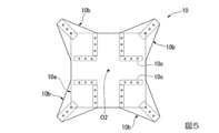
本実施形態の固定板10は、図5(及び図1から図4)に示すように、平面視で、正方形の4つの隅部を対角線の延長線に沿って外側に張り出すようにして略十字状に形成され、中央の正方形部分が応力伝達部10aとされ、4つの張り出した隅部がそれぞれ水平ブレースの端部をボルト接合する接合部10bとされている。
As shown in FIG. 5 (and FIGS. 1 to 4), the fixing
固定板10は、下弦材3の十字状に直交する鉄骨(弦材)の交点O1にその中心O2を合わせ、且つ対角線が下弦材3の直交する鉄骨の延設方向に対して45°の角度をなすように、また、下弦材3のフランジ3aの外面に面接触させて配設される。
The center O2 of the fixing
支持板11は、図6(a)、(c)(及び図1から図4)に示すように、矩形板状に形成され、長辺の一側部側に一面から他面に貫通する複数のボルト挿通孔が一側部に沿って所定の間隔をあけて穿設されている。そして、この支持板11は、下弦材3のフランジ3aの内面に他側部側を面接触させつつ、固定板10に穿設されたボルト挿通孔と、一側部側のボルト挿通孔を連通させるように配設される。そして、互いに連通したボルト挿通孔にボルトを挿通しナットを緊締することにより、固定板10と支持板11の他側部側とで下弦材3のフランジ3aを挟み込み、固定板10と下弦材3を接合することができるように構成されている。
As shown in FIGS. 6 (a) and 6 (c) (and FIGS. 1 to 4), the
また、本実施形態では、下弦材3の直交する鉄骨の交点O1、ひいては固定板10の中心O2を挟んで、直交する各鉄骨の一方の側と他方の側、さらに一方の側と他方の側のウェブを挟んで両側のフランジ3aを挟み込むようにそれぞれ支持板11が配設されている。すなわち、本実施形態では、8つの支持板11が設けられ、直交する各鉄骨の一方の側と他方の側のフランジ3aを固定板10と各支持板11で挟み込んで、固定板10が下弦材3の所定位置に接合配置されている。
Further, in the present embodiment, one side and the other side of each of the orthogonal steel frames, and further one side and the other side are sandwiched between the intersection O1 of the orthogonal steel frames of the
さらに、本実施形態では、図1から図4、図6(b)、(c)に示すように、支持板11の一側部側と介装材12と固定板10のボルト挿通孔を連通させて各支持板11の一側部側と固定板10の間に介装材12を介装し、これら支持板11の一側部側と介装材12と固定板10を一体にボルト接合するように構成されている。また、介装材12は、矩形平板状に形成され、一側部がフランジ3aの端部に対向し当接するように配設される。
Further, in the present embodiment, as shown in FIGS. 1 to 4, 6 (b) and 6 (c), one side of the
さらに、介装材12は、固定板10に面接触する一面を摩擦面処理して形成されている。また、固定板10は、介装材12と面接触する部分10cが摩擦面処理されている。これにより、介装材12と固定板10が摩擦接合され、フランジの外側面と介装板12の内側面の接触による支圧によって、既存部材(弦材)と新設部材(水平ブレース)の力の伝達が可能となる。さらに、支持板11がフランジ3aの上にかぶさっているため、固定板10の自重を支え、落下することがない。
Further, the
そして、上記構成からなる本実施形態のあと付けブレースの接合構造Aにおいては、新たに追加する水平ブレース6が固定板10の対角線上の4隅の接合部10bにそれぞれボルト接合して配設される。
In the post-attachment brace joint structure A of the present embodiment having the above configuration, the newly added
これにより、屋根面で発生する水平方向の地震力は、直交する上弦材や下弦材の鉄骨に集まるが、直交する弦材と対角線上に配置された水平ブレース6の交点中心O1、O2が一致しているため、偏心による2次応力が発生せず、力学的に明快な補強を行うことができる。
As a result, the horizontal seismic force generated on the roof surface is concentrated on the steel frames of the orthogonal upper and lower chords, but the center O1 and O2 of the intersections of the
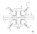
より具体的に、図7は本実施形態のあと付けブレースの接合構造Aを用いて水平ブレース6を設置した場合の節点における力の流れを示している。
More specifically, FIG. 7 shows the force flow at the node when the
図7中の矢印S1は同節点の支配面積が受け持つ水平力(地震力)を表わし、矢印S2は、矢印S1が形を変え、下弦材3の下フランジ3aに分散していることを表わしている。また、矢印S3は矢印S2の反力として、同フランジ3aからの支圧を介装材12が受けている様子を表している。
The arrow S1 in FIG. 7 represents the horizontal force (seismic force) that the area controlled by the node is responsible for, and the arrow S2 indicates that the arrow S1 changes its shape and is dispersed in the
ここで、新たに追加される水平ブレース6では、水平力が確実に水平ブレース6に伝達できること、ブレース6の縁端が確実に既存部材(下弦材3)に固定されていることが重要になる。これに対し、図7に示すように、本実施形態のあと付けブレースの接合構造Aを用いた場合には、介装材12が受けた支圧力が摩擦接合によって固定板10に伝わり、地震力とは逆向きの矢印S3として水平ブレース6(61)に流れる。
Here, in the newly added
また、水平ブレース6は網の目状(略格子状)に各弦材の直交節点を結んでいるため、他の節点で発生した水平力が水平ブレース6を伝わり流れてくる。図7ではこのような他の水平ブレース6からの力を矢印S4で表わしており、この力に関してはそのまま固定板を通じて逆側の水平ブレース6(61)へ伝達されることになる。
Further, since the
すなわち、固定板には、節点の支配面積からくる地震力と、接合される水平ブレースによって他の節点から来る軸力とが導入されることになるが、固定板が面外変形の無い1枚板であるため、水平力のハブとしてスムーズな力の伝達が可能になる。 That is, the seismic force coming from the area controlled by the node and the axial force coming from other nodes due to the joined horizontal braces are introduced into the fixed plate, but the fixed plate is one without out-of-plane deformation. Since it is a plate, it can transmit force smoothly as a hub for horizontal force.
一方、固定板10は既存部材(下弦材3)に対してずれることがあってはならない。
これに対し、本実施形態のあと付けブレースの接合構造Aにおいては、固定板10がフランジ3aから受ける支圧力が直交方向であるため、介装材12とフランジ3aの外側面を密着させて高力ボルトで固定することで2方向の固定を施し、幾何学的に移動が生じないようにしている。
On the other hand, the fixing
On the other hand, in the joint structure A of the retrofit brace of the present embodiment, since the supporting pressure received by the fixing
以上のような仕組みにより、本実施形態のあと付けブレースの接合構造Aでは、既存部材(下弦材3)と新規部材(水平ブレース6)と間に摩擦接合を使用せず、既存部材に対して支持板11がずれないようにし、力の流れがスムーズになるようにしている。
Due to the above mechanism, in the joint structure A of the retrofit brace of the present embodiment, the frictional joint between the existing member (lower chord member 3) and the new member (horizontal brace 6) is not used, and the existing member is not used. The
また、本実施形態のあと付けブレースの接合構造Aは、主要構成部材が固定板10、支持板11、介装材12の3種だけであり、全て鋼板を用い、高力ボルト接合用の孔開け加工を施し、介装材12の両面と介装材12が接する固定板10と支持板11の当接面を摩擦面処理するだけで、容易に製作することができる。
Further, in the joint structure A of the retrofit brace of the present embodiment, the main constituent members are only three types of the fixing
すなわち、本実施形態のあと付ブレースの接合構造Aにおいては、1施工箇所(1節点)における部材数が少なく、簡単に入手可能な材料と加工が行えるため、特に大量の数量を必要とする大空間建物の耐震改修で大きなコスト削減を図ることが可能になる。 That is, in the joint structure A of the retrofit brace of the present embodiment, the number of members at one construction site (one node) is small, and easily available materials and processing can be performed. Seismic retrofitting of spatial buildings will enable significant cost reductions.
したがって、本実施形態のあと付けブレースの接合構造Aにおいては、水平ブレース6を既存部材に固定する部品が一般に使用される鋼板とボルトのみから構成されるため、材料が少なく、入手しやすく、加工コストを小さく抑えることができる。このため、施工箇所数が無数に存在する工場施設においては、経済的な効果が非常に大きい。
Therefore, in the joint structure A of the retrofit brace of the present embodiment, since the parts for fixing the
また、現場での溶接や孔開け加工、現場での摩擦面処理作業が不要であり、施工が簡単である。 In addition, on-site welding, drilling, and on-site friction surface treatment work are not required, and construction is easy.
また、固定板10をフランジ3aの外側に固定するため、既存部材を避けた配置が可能となり、この点からも簡単に施工できる。
Further, since the fixing
さらに、ブレース6の軸線が通っているため、偏心曲げなどの2次応力が発生せず、固定部の応力の流れが明快であり、構造設計がしやすい。
Further, since the axis of the
さらに、本発明に係る介装材12は、既存弦材のフランジ3aからの支圧力を受ける働きと、既存フランジ3aの上側へ支持板11を配置する目的で設置されるため、特許文献3のようなスペーサ板厚の高精度の管理を行うことが不要である。
Further, since the
なお、水平ブレース6の材料には一般形鋼、JISブレースを使用できる他、固定板の中心に構造用ケーブルの固定金物を設置することで、施工時の運搬に場所をとらず、圧縮軸力で座屈の心配が無い構造用ケーブルを使用することもできる。また、本実施形態では、あと付けブレースの接合構造Aを下弦材3側に取り付けるものとして説明を行ったが、本発明に係るあと付けブレースの接合構造Aは、上弦材2側にも下弦材3側にも施工することができ、上弦材2側、下弦材3側のどちらであっても同様の効果が得られることは言うまでもない。
In addition, general shaped steel and JIS brace can be used as the material of the
以上、本発明に係るあと付けブレースの接合構造の一実施形態について説明したが、本発明は上記の一実施形態に限定されるものではなく、その趣旨を逸脱しない範囲で適宜変更可能である。 Although one embodiment of the joint structure of the retrofit brace according to the present invention has been described above, the present invention is not limited to the above-mentioned one embodiment and can be appropriately changed without departing from the spirit of the present invention.
例えば、上記の実施形態では大空間/大スパンの屋根面を構成する大梁を上弦材2と下弦材3を持つトラス形式とした場合であったが、大梁をH形鋼とした場合でも、H形鋼がウェブとフランジを有する鉄骨からなる水平の既存部材であることに変わりがなく、本発明が適用できることは言うまでもない。
For example, in the above embodiment, the girder constituting the roof surface of a large space / large span is a truss type having an
また、図8に示すように、支持板11にリブ11aを設けるようにしてもよい。この場合には、リブ11aによって、支持板11の面外変形を防止することが可能になるとともに、下弦材3(あるいは上弦材2:既存部材)と介装板12の接触による力の伝達を有効に働かせることが可能になる。
Further, as shown in FIG. 8, the
1 屋根面架構(大梁)
2 上弦材(既存部材)
3 下弦材(既存部材)
3a フランジ
4 束材
5 ラチス材
6 水平ブレース(あと付けブレース)
10 固定板
10a 応力伝達部
10b 接合部
10c 当接面
11 支持板
11a リブ
12 介装板(スペーサ)
A あと付けブレースの接合構造
1 Roof frame (girder)
2 Upper chord material (existing member)
3 Lower chord material (existing member)
10
A Post-attachment brace joint structure
Claims (3)
前記既存部材のフランジの外側の面に対向配置され、前記水平ブレースを接続する板状の固定板と、
前記固定板とともに前記既存部材のフランジを挟み込むように配設される支持板と、
前記固定板と前記支持板の間に介装される介装板と、
前記固定板と前記支持板をボルト接合するボルト及びナットとを備え、
前記フランジにおける水平方向を臨む外面と、前記介装板における前記外面と対向配置された内面と、が近接配置され、
前記介装板は、前記固定板および前記支持板と一体にボルト接合されており、
前記介装板と前記固定板とが摩擦接合されており、
前記既存部材と前記水平ブレースの力の伝達を、前記フランジの前記外面と前記介装板の前記内面との接触による支圧によって行うように構成され、
前記固定板の平面視の中心と、前記既存部材である直交する鉄骨の交点の中心と、が一致するように前記固定板が設けられ、
前記固定板は、平面視で正方形の4つの隅部を対角線の延長線に沿って外側に張り出すようにして略十字状に形成され、
前記水平ブレースの端部は、前記固定板の前記4つの隅部に接合され、
前記水平ブレースは、前記固定板の前記対角線の延長線に沿って配置されていることを特徴とするあと付けブレースの接合構造。 It is a structure for attaching a horizontal brace to an existing member formed by using a steel frame having a flange.
A plate-shaped fixing plate arranged to face the outer surface of the flange of the existing member and connecting the horizontal brace, and a plate-shaped fixing plate.
A support plate arranged so as to sandwich the flange of the existing member together with the fixing plate,
An interposition plate interposed between the fixing plate and the support plate, and
A bolt and a nut for bolting the fixing plate and the support plate are provided.
The outer surface of the flange facing the horizontal direction and the inner surface of the interposition plate facing the outer surface are arranged in close proximity to each other.
The interposition plate is bolted integrally with the fixing plate and the support plate.
The interposition plate and the fixing plate are frictionally joined to each other.
It is configured to transmit the force of the existing member and the horizontal brace by supporting pressure by contact between the outer surface of the flange and the inner surface of the interposition plate.
The fixing plate is provided so that the center of the fixing plate in a plan view and the center of the intersection of the orthogonal steel frames which are the existing members coincide with each other.
The fixing plate is formed in a substantially cross shape so that the four corners of the square project outward along the extension of the diagonal line in a plan view.
The ends of the horizontal braces are joined to the four corners of the fixing plate.
The horizontal brace is a joint structure of a retrofit brace, characterized in that the horizontal brace is arranged along an extension of the diagonal line of the fixing plate .
前記介装板と前記固定板の互いに面接触する部分が摩擦力を増大させるように摩擦面処理されていることを特徴とするあと付けブレースの接合構造。 In the joint structure of the retrofit brace according to claim 1,
A post-attachment brace joint structure characterized in that a portion of the interposition plate and the fixing plate that are in surface contact with each other is subjected to a friction surface treatment so as to increase a frictional force.
前記支持板には、前記支持板の面外変形を防止するとともに、前記既存部材と前記介装板との接触による支圧によって力を伝達させるためのリブが設けられていることを特徴とするあと付けブレースの接合構造。 In the joint structure of the retrofit brace according to claim 1 or 2.
The support plate is characterized in that it is provided with ribs for preventing out-of-plane deformation of the support plate and transmitting a force by bearing pressure due to contact between the existing member and the interposition plate. Bonding structure of retrofit brace.
Priority Applications (1)
| Application Number | Priority Date | Filing Date | Title |
|---|---|---|---|
| JP2017161348A JP7033406B2 (en) | 2017-08-24 | 2017-08-24 | Post-attachment brace joint structure |
Applications Claiming Priority (1)
| Application Number | Priority Date | Filing Date | Title |
|---|---|---|---|
| JP2017161348A JP7033406B2 (en) | 2017-08-24 | 2017-08-24 | Post-attachment brace joint structure |
Publications (2)
| Publication Number | Publication Date |
|---|---|
| JP2019039201A JP2019039201A (en) | 2019-03-14 |
| JP7033406B2 true JP7033406B2 (en) | 2022-03-10 |
Family
ID=65726203
Family Applications (1)
| Application Number | Title | Priority Date | Filing Date |
|---|---|---|---|
| JP2017161348A Active JP7033406B2 (en) | 2017-08-24 | 2017-08-24 | Post-attachment brace joint structure |
Country Status (1)
| Country | Link |
|---|---|
| JP (1) | JP7033406B2 (en) |
Families Citing this family (1)
| Publication number | Priority date | Publication date | Assignee | Title |
|---|---|---|---|---|
| JP6949691B2 (en) * | 2017-12-05 | 2021-10-13 | 清水建設株式会社 | Post-attached brace joint structure |
Citations (6)
| Publication number | Priority date | Publication date | Assignee | Title |
|---|---|---|---|---|
| JP2002180555A (en) | 2000-12-15 | 2002-06-26 | Nippon Steel Corp | Friction joint structure for steel by means of high- strength bolt |
| JP2007077643A (en) | 2005-09-13 | 2007-03-29 | Kumagai Gumi Co Ltd | Reinforcing method and reinforcing structure for existing steel member of steel construction |
| JP2007303066A (en) | 2006-05-08 | 2007-11-22 | Takenaka Komuten Co Ltd | Existing trussed frame reinforcing structure |
| JP2008002268A (en) | 2007-10-10 | 2008-01-10 | Penta Ocean Constr Co Ltd | Friction joint structure and seismic strengthening method of structure by high-tension bolt |
| JP2008267022A (en) | 2007-04-23 | 2008-11-06 | Takenaka Komuten Co Ltd | Brace installation structure for roof steel frame |
| JP2012251321A (en) | 2011-06-01 | 2012-12-20 | Miyazono Seisakusho:Kk | Support metal fitting for brace member and support structure for brace member |
-
2017
- 2017-08-24 JP JP2017161348A patent/JP7033406B2/en active Active
Patent Citations (6)
| Publication number | Priority date | Publication date | Assignee | Title |
|---|---|---|---|---|
| JP2002180555A (en) | 2000-12-15 | 2002-06-26 | Nippon Steel Corp | Friction joint structure for steel by means of high- strength bolt |
| JP2007077643A (en) | 2005-09-13 | 2007-03-29 | Kumagai Gumi Co Ltd | Reinforcing method and reinforcing structure for existing steel member of steel construction |
| JP2007303066A (en) | 2006-05-08 | 2007-11-22 | Takenaka Komuten Co Ltd | Existing trussed frame reinforcing structure |
| JP2008267022A (en) | 2007-04-23 | 2008-11-06 | Takenaka Komuten Co Ltd | Brace installation structure for roof steel frame |
| JP2008002268A (en) | 2007-10-10 | 2008-01-10 | Penta Ocean Constr Co Ltd | Friction joint structure and seismic strengthening method of structure by high-tension bolt |
| JP2012251321A (en) | 2011-06-01 | 2012-12-20 | Miyazono Seisakusho:Kk | Support metal fitting for brace member and support structure for brace member |
Also Published As
| Publication number | Publication date |
|---|---|
| JP2019039201A (en) | 2019-03-14 |
Similar Documents
| Publication | Publication Date | Title |
|---|---|---|
| US11441314B2 (en) | Wall connection system | |
| KR20130139029A (en) | Modular column joint structure using h shape steel plate | |
| JP6763653B2 (en) | Unit building | |
| JP4710067B2 (en) | Beam-column joint structure | |
| JP7033406B2 (en) | Post-attachment brace joint structure | |
| JP6292919B2 (en) | Frame structure and method for reinforcing frame structure | |
| JP4987776B2 (en) | Panel joining structure and method for building, building structure | |
| JP6752599B2 (en) | Seismic structure and seismic retrofitting method | |
| JP7116400B2 (en) | truss girder | |
| JP7162457B2 (en) | Joining structure of retrofitted brace | |
| KR102169828B1 (en) | Joint of columns | |
| JP2009030321A (en) | Portal frame by connection of composite beam and wooden pillar | |
| JP6949691B2 (en) | Post-attached brace joint structure | |
| JP7032051B2 (en) | Floor structure construction method and floor structure reuse method | |
| JP4260736B2 (en) | Steel house bearing wall structure | |
| JP7495309B2 (en) | Ladder-type load-bearing wall structure and portal structure | |
| JP7426253B2 (en) | truss beam | |
| JP2020105892A (en) | Column beam joint structure | |
| JP5004434B2 (en) | Steel house | |
| JPH08144368A (en) | Structure and method for connecting end plate type steel frame structure | |
| JP6292918B2 (en) | Frame structure and method for reinforcing frame structure | |
| JP2020002631A (en) | Column-beam joint structure | |
| JP2023002219A (en) | Bonding structure | |
| JP7358142B2 (en) | unit building | |
| JP2012140781A (en) | Vibration control structure for building wall section |
Legal Events
| Date | Code | Title | Description |
|---|---|---|---|
| A621 | Written request for application examination |
Free format text: JAPANESE INTERMEDIATE CODE: A621 Effective date: 20200701 |
|
| A977 | Report on retrieval |
Free format text: JAPANESE INTERMEDIATE CODE: A971007 Effective date: 20210621 |
|
| A131 | Notification of reasons for refusal |
Free format text: JAPANESE INTERMEDIATE CODE: A131 Effective date: 20210629 |
|
| A521 | Request for written amendment filed |
Free format text: JAPANESE INTERMEDIATE CODE: A523 Effective date: 20210825 |
|
| A131 | Notification of reasons for refusal |
Free format text: JAPANESE INTERMEDIATE CODE: A131 Effective date: 20211214 |
|
| A521 | Request for written amendment filed |
Free format text: JAPANESE INTERMEDIATE CODE: A523 Effective date: 20220112 |
|
| TRDD | Decision of grant or rejection written | ||
| A01 | Written decision to grant a patent or to grant a registration (utility model) |
Free format text: JAPANESE INTERMEDIATE CODE: A01 Effective date: 20220208 |
|
| A61 | First payment of annual fees (during grant procedure) |
Free format text: JAPANESE INTERMEDIATE CODE: A61 Effective date: 20220228 |
|
| R150 | Certificate of patent or registration of utility model |
Ref document number: 7033406 Country of ref document: JP Free format text: JAPANESE INTERMEDIATE CODE: R150 |