JP7033013B2 - Image coding device, image decoding device, their control method, and program - Google Patents
Image coding device, image decoding device, their control method, and program Download PDFInfo
- Publication number
- JP7033013B2 JP7033013B2 JP2018114689A JP2018114689A JP7033013B2 JP 7033013 B2 JP7033013 B2 JP 7033013B2 JP 2018114689 A JP2018114689 A JP 2018114689A JP 2018114689 A JP2018114689 A JP 2018114689A JP 7033013 B2 JP7033013 B2 JP 7033013B2
- Authority
- JP
- Japan
- Prior art keywords
- data
- quantization parameter
- subband
- quantization
- tile
- Prior art date
- Legal status (The legal status is an assumption and is not a legal conclusion. Google has not performed a legal analysis and makes no representation as to the accuracy of the status listed.)
- Active
Links
Images


Classifications
-
- H—ELECTRICITY
- H04—ELECTRIC COMMUNICATION TECHNIQUE
- H04N—PICTORIAL COMMUNICATION, e.g. TELEVISION
- H04N19/00—Methods or arrangements for coding, decoding, compressing or decompressing digital video signals
- H04N19/10—Methods or arrangements for coding, decoding, compressing or decompressing digital video signals using adaptive coding
- H04N19/102—Methods or arrangements for coding, decoding, compressing or decompressing digital video signals using adaptive coding characterised by the element, parameter or selection affected or controlled by the adaptive coding
- H04N19/124—Quantisation
-
- H—ELECTRICITY
- H04—ELECTRIC COMMUNICATION TECHNIQUE
- H04N—PICTORIAL COMMUNICATION, e.g. TELEVISION
- H04N19/00—Methods or arrangements for coding, decoding, compressing or decompressing digital video signals
- H04N19/10—Methods or arrangements for coding, decoding, compressing or decompressing digital video signals using adaptive coding
- H04N19/134—Methods or arrangements for coding, decoding, compressing or decompressing digital video signals using adaptive coding characterised by the element, parameter or criterion affecting or controlling the adaptive coding
- H04N19/154—Measured or subjectively estimated visual quality after decoding, e.g. measurement of distortion
-
- H—ELECTRICITY
- H04—ELECTRIC COMMUNICATION TECHNIQUE
- H04N—PICTORIAL COMMUNICATION, e.g. TELEVISION
- H04N19/00—Methods or arrangements for coding, decoding, compressing or decompressing digital video signals
- H04N19/10—Methods or arrangements for coding, decoding, compressing or decompressing digital video signals using adaptive coding
- H04N19/169—Methods or arrangements for coding, decoding, compressing or decompressing digital video signals using adaptive coding characterised by the coding unit, i.e. the structural portion or semantic portion of the video signal being the object or the subject of the adaptive coding
- H04N19/1883—Methods or arrangements for coding, decoding, compressing or decompressing digital video signals using adaptive coding characterised by the coding unit, i.e. the structural portion or semantic portion of the video signal being the object or the subject of the adaptive coding the unit relating to sub-band structure, e.g. hierarchical level, directional tree, e.g. low-high [LH], high-low [HL], high-high [HH]
-
- H—ELECTRICITY
- H04—ELECTRIC COMMUNICATION TECHNIQUE
- H04N—PICTORIAL COMMUNICATION, e.g. TELEVISION
- H04N19/00—Methods or arrangements for coding, decoding, compressing or decompressing digital video signals
- H04N19/44—Decoders specially adapted therefor, e.g. video decoders which are asymmetric with respect to the encoder
-
- H—ELECTRICITY
- H04—ELECTRIC COMMUNICATION TECHNIQUE
- H04N—PICTORIAL COMMUNICATION, e.g. TELEVISION
- H04N19/00—Methods or arrangements for coding, decoding, compressing or decompressing digital video signals
- H04N19/60—Methods or arrangements for coding, decoding, compressing or decompressing digital video signals using transform coding
- H04N19/63—Methods or arrangements for coding, decoding, compressing or decompressing digital video signals using transform coding using sub-band based transform, e.g. wavelets
Description
本発明は、画像の符号化技術に関するものである。 The present invention relates to an image coding technique.
デジタルカメラやビデオカメラは、撮像素子として、CCD又はCMOSイメージセンサを採用している。また、単板式の撮像素子の場合、いわゆるベイヤ配列のカラーフィルタを通すことにより、緑、青、赤の画素データを得ることになる。デジタルカメラでは、ベイヤ配列の緑、青、赤データ(以下、RAWデータ)に対し、デモザイク処理、ノイズ除去処理、光学歪み補正、色補正処理等を含む現像処理を行い最終的な画像データを生成することになる。そして、静止画の場合はJPEG、動画の場合はH.264等の符号化方式により圧縮画像データを記録媒体に記録することになる。一方で、撮像装置の中には、ユーザの好みに応じて現像処理が実行できるようにするため、現像処理前のRAWデータを記録する機能を搭載しているものも少なくない。 Digital cameras and video cameras employ a CCD or CMOS image sensor as an image pickup device. Further, in the case of a single-panel image pickup element, green, blue, and red pixel data can be obtained by passing through a so-called Bayer array color filter. In a digital camera, the green, blue, and red data (hereinafter referred to as RAW data) of the bayer array are subjected to development processing including demosaic processing, noise removal processing, optical distortion correction, color correction processing, etc. to generate final image data. Will be done. Then, in the case of a still image, JPEG, and in the case of a moving image, H. Compressed image data will be recorded on a recording medium by a coding method such as 264. On the other hand, many image pickup devices are equipped with a function of recording RAW data before the development process so that the development process can be executed according to the user's preference.
RAWデータの記録形式には、非圧縮又は可逆圧縮形式を採用する場合が多く、一般に記録される圧縮RAWデータのサイズは、現像後の通常の画像の圧縮画像データよりも大きい。しかし、撮像素子は高密度化、高画素化される一方であり、RAWデータをコンパクトに記録することが重要となってきている。そこで、視覚的に無損失な非可逆圧縮形式として、RAWデータから複数のカラーチャネルを生成し、各チャネルに対して2次元離散ウェーブレット変換を行い、生成された各サブバンドを個別に量子化して圧縮して符号化データとして記録する方法等が提案されている(特許文献1を参照)。 As the recording format of the RAW data, an uncompressed or lossless compressed format is often adopted, and the size of the compressed RAW data generally recorded is larger than the compressed image data of a normal image after development. However, the density and the number of pixels of the image sensor are increasing, and it is becoming important to record RAW data compactly. Therefore, as a visually lossless lossy compression format, multiple color channels are generated from RAW data, two-dimensional discrete wavelet transform is performed for each channel, and each generated subband is individually quantized. A method of compressing and recording as encoded data has been proposed (see Patent Document 1).
ここで、RAWデータからR、B、G1、G2の4つのカラーチャネルのデータを生成し、それぞれのチャネルのデータに対して2次元離散ウェーブレット変換による3階層のオクターブ分割を行う場合を考察する。この場合、1チャネルにつき10個のサブバンドが生成される。チャネル数は4つであるから、トータルで4×10個のサブバンドが生成されることになる。これらのサブバンドを個別に量子化する場合、4×10=40個の量子化パラメータを必要とする。更に画面内の特徴に応じて、所定ブロック単位のより細かい量子化制御を行うこと想定した場合、4×10×ブロック分割数分の量子化パラメータが必要となる。つまり、RAWデータの圧縮符号化の際の量子化パラメータのデータ量も肥大化してしまう。これでは、視覚的に無損失な画質を維持しつつ、コンパクトにRAWデータを記録するのは困難である。 Here, consider a case where data of four color channels R, B, G1 and G2 are generated from RAW data, and the data of each channel is divided into three layers of octaves by two-dimensional discrete wavelet transform. In this case, 10 subbands are generated per channel. Since the number of channels is 4, a total of 4 × 10 subbands will be generated. Quantizing these subbands individually requires 4 × 10 = 40 quantization parameters. Further, assuming that finer quantization control in a predetermined block unit is performed according to the features in the screen, the quantization parameters for 4 × 10 × the number of block divisions are required. That is, the amount of data of the quantization parameter at the time of compression coding of RAW data also becomes bloated. With this, it is difficult to record RAW data compactly while maintaining visually lossless image quality.
本発明は上記問題に鑑みなされたものであり、RAW画像データを複数のタイルに分割して符号化を行う際に、タイル境界での画質劣化を抑制しつつ、柔軟な量子化制御により非可逆圧縮を実現しつつ、符号化データに含める量子化パラメータのデータ量を抑制することで、コンパクトにRAWデータを記録することを可能にする技術を提供する。 The present invention has been made in view of the above problems, and when the RAW image data is divided into a plurality of tiles and encoded, it is irreversible by flexible quantization control while suppressing deterioration of image quality at the tile boundary. We provide a technology that enables compact RAW data recording by suppressing the amount of quantization parameter data included in the coded data while realizing compression.
この課題を解決するため、例えば本発明の画像符号化装置は以下の構成を備える。すなわち、
ベイヤ配列のRAW画像データを符号化する符号化装置であって、
符号化対象のRAW画像データを複数のタイルに分割する分割手段と、
該分割手段により分割された前記複数のタイル毎に互いに異なる成分を持つ複数のチャネルのプレーンを生成する生成手段と、
該生成手段で生成した各チャネルのプレーンに対して周波数変換し、複数の分解レベルのサブバンドデータを生成する変換手段と、
前記RAW画像データの同じ領域に対応する複数のセグメントに分割するために、前記複数のサブバンドデータをそれぞれ同じ数のセグメントに分割し、セグメント毎に複数のサブバンドデータで共通となる第1の量子化パラメータを決定する制御手段と、
前記制御手段により決定された第1の量子化パラメータに基づいて、前記変換手段で得たサブバンドデータをセグメント毎にそれぞれ量子化する量子化手段と、
前記量子化により得られた量子化結果を、サブバンド毎に符号化する符号化手段と、
を有し、
前記生成手段は、
着目タイルから前記複数のチャネルのプレーンを生成する際に、前記着目タイルと、前記着目タイルの隣接タイル内の前記着目タイルとの境界から所定の距離までのデータとから、前記複数のチャネルのプレーンを生成し、
前記制御手段は、
前記着目タイルのサブバンドデータを前記複数のセグメントに分割して前記第1の量子化パラメータを決定し、前記隣接タイルのサブバンドデータは、前記着目タイルとの境界を介して隣接するセグメントの量子化パラメータを適応することを特徴とする。
In order to solve this problem, for example, the image coding apparatus of the present invention has the following configuration. That is,
A coding device that encodes RAW image data of a Bayer array.
A dividing means for dividing the RAW image data to be encoded into a plurality of tiles, and
A generation means for generating a plane of a plurality of channels having different components for each of the plurality of tiles divided by the division means, and a generation means.
A conversion means that frequency-converts the plane of each channel generated by the generation means to generate subband data of a plurality of decomposition levels, and a conversion means.
In order to divide the RAW image data into a plurality of segments corresponding to the same region, the plurality of subband data are each divided into the same number of segments, and each segment is common to the plurality of subband data. Control means to determine the quantization parameters and
A quantization means that quantizes the subband data obtained by the conversion means for each segment based on the first quantization parameter determined by the control means, and
A coding means for encoding the quantization result obtained by the above-mentioned quantization for each subband,
Have,
The generation means is
When generating the planes of the plurality of channels from the tiles of interest, the planes of the plurality of channels are obtained from the data from the boundary between the tiles of interest and the tiles of interest in the adjacent tiles of the tiles of interest to a predetermined distance. To generate,
The control means is
The subband data of the tile of interest is divided into the plurality of segments to determine the first quantization parameter, and the subband data of the adjacent tile is the quantum of the adjacent segment via the boundary with the tile of interest. It is characterized by adapting the quantization parameters.
本発明によれば、RAW画像データを複数のタイルに分割して符号化を行う際に、タイル境界での画質劣化を抑制しつつ、柔軟な量子化制御により非可逆圧縮を実現しつつ、符号化データに含める量子化パラメータのデータ量を抑制することで、コンパクトにRAWデータを記録することが可能になる。 According to the present invention, when the RAW image data is divided into a plurality of tiles and encoded, the code is realized while suppressing the deterioration of the image quality at the tile boundary and realizing the lossy compression by the flexible quantization control. By suppressing the amount of quantization parameter data included in the conversion data, it becomes possible to record RAW data compactly.
以下、添付図面に従って本発明に係る実施形態を詳細に説明する。なお、以下に示す実施形態における構成は一例に過ぎず、本発明は図示された構成に限定されるものではない。まず、実施形態における前提部分について説明する。 Hereinafter, embodiments according to the present invention will be described in detail with reference to the accompanying drawings. The configuration in the embodiment shown below is only an example, and the present invention is not limited to the configuration shown in the illustration. First, the premise part in the embodiment will be described.
[第1の実施形態]
図1(a)は、実施形態における撮像装置100における符号化に係る主要ブロック構成図である。撮像装置100は、例えばデジタルカメラ、デジタルビデオカメラとして実現することができる。また、それ以外に、例えばパーソナルコンピュータ、携帯電話、スマートフォン、PDA、タブレット端末、携帯型メディアプレーヤなどの任意の情報処理端末或いは画像処理装置として実現することもできる。なお、図1(a)は、撮像装置であるデジタルカメラ等として機能する場合を考慮して撮像部102を含む構成を示した。しかし、RAW画像を記録、再生することが可能な画像符号化装置、画像復号装置、画像記録装置、画像圧縮装置、画像復元装置等に適用できるので、RAW画像データの発生源である撮像部102は必須ではない。なぜなら、RAW画像データの発生源としては、RAW画像データを記憶している記憶媒体、ネットワーク上のファイルサーバでも構わず、その種類は問わないからである。
[First Embodiment]
FIG. 1A is a main block configuration diagram relating to coding in the
撮像装置100において、制御部101は、撮像装置100を構成する各処理部を制御するものであり、CPU、CPUが実行するプログラムを格納しているROM、並びに、ワークエリアとして使用するRAMで構成される。撮像部102は、光学レンズ、絞り、フォーカス制御及びレンズ駆動部を含む光学ズームが可能なレンズ光学系と、レンズ光学系からの光情報を電気信号に変換するCCDイメージセンサ又はCMOSイメージセンサなどの撮像素子を含む。撮像部102は、撮像素子により得られた電気信号をディジタル信号へ変換して得たRAWデータ(RAW画像データとも言う)を、RAWデータ符号化・復号部103へ供給する。
In the
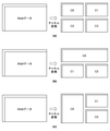
ここで1枚のRAWデータは、図1(b)に示すように、受光した画素領域である有効撮像領域と遮光された画素領域であるオプティカルブラック領域とで構成される。各画素はR(赤)、G1(緑)、G2(緑)、B(青)の周期的なパターンで構成されている。人間の視覚感度は緑に対して高いことが知られている。そこで、画像としての解像感に対して有利になるように緑を、赤や青に対して2倍の個数となるように割り当てている。本実施形態ではRAWデータは、ベイヤ配列の4色要素で構成されるものとするが、その配列や色要素はこの構成に限定されず他の方式であっても良い。 Here, as shown in FIG. 1B, one RAW data is composed of an effective imaging region which is a received pixel region and an optical black region which is a shaded pixel region. Each pixel is composed of a periodic pattern of R (red), G1 (green), G2 (green), and B (blue). It is known that human visual sensitivity is high with respect to green. Therefore, green is assigned so as to be twice as many as red and blue so as to be advantageous for the resolution as an image. In the present embodiment, the RAW data is composed of four color elements of the bayer arrangement, but the arrangement and the color elements are not limited to this configuration and may be another method.
RAWデータ符号化・復号部103は、撮像部102が取得したRAWデータを符号化し、生成した符号化データをメモリ105へ書き込む。また、符号化されていないRAWデータを記録媒体107から取得して、本実施形態に対応する符号化処理を実行して符号化データを生成してもよい。また、RAWデータ符号化・復号部103は、符号化データを復号してRAWデータを復元することができる。RAWデータ符号化・復号部103に関わる詳細な構成や動作については後述する。
The RAW data coding /
メモリI/F部104は、各処理部からのメモリ105へのメモリ・アクセス要求、メモリ105に対する読み出し又は書き込み要求の調停処理を行う。メモリ105は、撮像装置100を構成する各処理部から出力される各種データを格納するため、例えば高速な揮発性メモリ(SRAMがその代表)である。記録処理部106は、メモリ105へ格納された符号化データを読み出し、所定の記録フォーマット化を行い記録媒体107へ記録する。また、記録処理部106は、復号のため、記録媒体107から符号化データを読み出し、メモリ105への格納も行う。記録媒体107は、例えば不揮発性メモリで構成される記録メディアであり、撮像装置100に対して着脱可能に構成されている。以上、実施形態における撮像装置100の符号化に係る主要部を説明した。
The memory I /
続いて、RAWデータ符号化・復号部103の詳細な構成及び処理の流れについて図2(a)及び図2(b)に示すブロック図を参照しながら説明を行う。図2(a)は、RAWデータ符号化・復号部103のうちRAWデータ符号化部103Eの構成を示し、図2(b)はRAWデータ符号化・復号部103のうちRAWデータ復号部103Dの構成を示している。
Subsequently, the detailed configuration and processing flow of the RAW data coding /
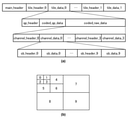
図2(a)においてRAWデータ符号化部103Eは、主に、チャネル変換部201、周波数変換部202、量子化パラメータ生成部203、量子化部204、符号化部205及び量子化パラメータ符号化部206で構成されている。チャネル変換部201は、図3(a)に示すように、入力されたベイヤ配列のRAWデータから、それぞれが単一成分で表される、複数のチャネル(実施形態ではC0乃至3の4つのチャネル)のプレーンデータに変換する。周波数変換部202、量子化部204は、変換により得られたチャネル数に対応するブロックが用意され、並列に処理される。本実施形態では、チャネル変換部201は、まず、RAWデータをベイヤ配列のR、G1、G2、B毎に4つのチャネルへ変換し、更にR、G1、G2、Bに対して、以下の変換式(1)によりC0乃至C3の4つのチャネルへ変換する。
C0=a+c
C1=B-G2 …(1)
C2=R-G1
C3=b-a
式中、a=G2+floor(C1/2)、b=G1+floor(C2/2)、c=a+floor(C3/2)である。ここで、floor(x)は、実数x以下の最大整数を返す床関数である。
In FIG. 2A, the RAW
C0 = a + c
C1 = B-G2 ... (1)
C2 = R-G1
C3 = ba
In the formula, a = G2 + floor (C1 / 2), b = G1 + floor (C2 / 2), c = a + floor (C3 / 2). Here, floor (x) is a floor function that returns the maximum integer less than or equal to the real number x.
尚、ここでは図3(a)に示すように4つのチャネルへ変換する構成例を示しているが、図3(b)や図3(c)に示すようにR、B、及び、G1とG2を合わせたGの3つのチャネルへ変換しても良く、チャネル数や変換方法は上記以外の方法であっても良い。要するに、元のベイヤ配列のRAWデータを再現できれば良い。 Although a configuration example for converting to four channels is shown here as shown in FIG. 3 (a), R, B, and G1 are shown as shown in FIGS. 3 (b) and 3 (c). It may be converted into three channels of G including G2, and the number of channels and the conversion method may be a method other than the above. In short, it suffices if the RAW data of the original bayer array can be reproduced.
次に、周波数変換部202は、チャネル単位のプレーンデータに所定の分解レベル(以降、単に「レベル」または「lev」と呼ぶ)で離散ウェーブレット変換による周波数変換処理を行い、生成された複数のサブバンドデータ(変換係数)を量子化パラメータ生成部203及び量子化部204へ出力する。
Next, the
なお、周波数変換部202と量子化部204との間の、量子化部204の直前には適当な容量のバッファが設けられている。詳細は後述する説明から明らかになるが、量子化部204が着目ブロック内の着目セグメントの変換係数を量子化する際に、量子化パラメータ生成部203はその着目セグメントに対する量子化パラメータを決定する時間が必要なためである。
A buffer having an appropriate capacity is provided between the
図4(a)は、lev=1のサブバンド分割処理に関わる離散ウェーブレット変換を実現するためのフィルタバンク構成を示している。離散ウェーブレット変換処理を水平、垂直方向に実行することで、図4(b)に示すように、1つの低周波数サブバンドLLと、3つの高周波数サブバンドHL、LH、HHが得られる。図4(a)に示すローパスフィルタ(以降、lpfと呼ぶ)及びハイパスフィルタ(以降、hpfと呼ぶ)の伝達関数を次式(2)、(3)に示す。
lpf(z)=(-z-2+2z-1+6+2z-z2)/8 …(2)
hpf(z)=(-z-1+2-z)/2 …(3)
また、図4(a)における「↓2」は2対1のダウンサンプリングを表す。従って、水平方向と垂直方向とで1回ずつのダウンサンプリングが実行されるので、1回のウェーブレット変換で得られる個々のサブバンドのサイズは元のサイズの1/4となる。levが1よりも大きい場合には、直前のレベルで生成された低周波数サブバンド(LL)に対して、再帰的にサブバンド分割を行うことになる。例えばlev=3の場合は、図4(c)に示すように10個のサブバンドに対応したサブバンドデータが生成される。尚、ここでは離散ウェーブレット変換は式(2)、(3)に示すように5タップのlpfと3タップのhpfで構成しているが、これとは異なるタップ数及び異なる係数のフィルタ構成であっても良い。
FIG. 4A shows a filter bank configuration for realizing the discrete wavelet transform related to the subband division process of lev = 1. By executing the discrete wavelet transform process in the horizontal and vertical directions, one low frequency subband LL and three high frequency subbands HL, LH, and HH can be obtained as shown in FIG. 4 (b). The transfer functions of the low-pass filter (hereinafter referred to as lpf) and the high-pass filter (hereinafter referred to as hpf) shown in FIG. 4A are shown in the following equations (2) and (3).
lpf (z) = (-z -2 + 2z -1 + 6 + 2z-z 2 ) / 8 ... (2)
hpf (z) = (-z -1 + 2-z) / 2 ... (3)
Further, "↓ 2" in FIG. 4A represents 2 to 1 downsampling. Therefore, since the downsampling is performed once in the horizontal direction and once in the vertical direction, the size of each subband obtained by one wavelet transform is 1/4 of the original size. When the lev is larger than 1, the low frequency subband (LL) generated at the immediately preceding level is recursively subbanded. For example, when lev = 3, subband data corresponding to 10 subbands is generated as shown in FIG. 4C. Here, the discrete wavelet transform is composed of a 5-tap lpf and a 3-tap hpf as shown in the equations (2) and (3), but the filter configuration has a different number of taps and different coefficients. May be.
量子化パラメータ生成部203は、周波数変換部202により生成されたサブバンドデータ(変換係数)に対して量子化処理を行うための全チャネル、全サブバンドに共通の第1の量子化パラメータを生成し、量子化パラメータ符号化部206へ出力する。また、量子化パラメータ生成部203は、第1の量子化パラメータから各チャネル、各サブバンドのための個別の第2の量子化パラメータを生成し、量子化部204へ供給する。第1の量子化パラメータ及び第2の量子化パラメータの生成単位やその生成方法については、図5から図7等を参照して後述する。
The quantization
量子化部204は、周波数変換部202から入力されたサブバンドデータ(変換係数)に対して量子化パラメータ生成部203から供給された第2の量子化パラメータに基づき量子化処理を行い、量子化結果として量子化後のサブバンドデータ(変換係数)を符号化部205へ出力する。
The
符号化部205は、量子化部204から入力された量子化後のサブバンドデータ(変換係数)に対して、サブバンド毎にラスタースキャン順で予測差分型エントロピー符号化を行う。これにより、量子化後のサブバンドデータはサブバンド単位で符号化されことになる。符号化部205は、図4(d)に示すように符号化対象データ(変換係数)に対して、既に符号化済みの周辺データ(図示のa,b,c)からMED(Median Edge Detector)予測により予測値pdを生成する。そして、符号化部205は、符号化対象データxの値xdと予測値pdとの差分データを、例えばハフマン符号化、ゴロム符号化等によりエントロピー符号化を行い、生成した符号化データをメモリ105へ格納する。ラスタースキャン順に符号化することになるので、符号化対象データがサブバンドの最初のラインや左両端に位置する場合、周辺データのいくつかが存在しない(サブバンド外)ことになる。その場合は、そのような存在しない周辺データは予め設定された値と持つものとする。また、特に、符号化対象データがサブバンドの先頭位置(左上隅位置)にある場合、周辺データの全てが存在しないことになるので、その符号化対象データxの値xdがそのまま符号化されるものとする。そして、それ以降の符号化対象データについては差分データが符号化される。尚、予測符号化方式やエントロピー符号化方式は、他の方式であっても良い。また、各サブバンド別にライン単位に発生した発生符号量を量子化パラメータ生成部203へ供給する。また、符号化部205が生成する符号化データの具体的なデータ構造については図9及び図10を参照して後述する。
The
量子化パラメータ符号化部206は、量子化パラメータ生成部203から入力された第1の量子化パラメータを符号化する処理部である。量子化パラメータ符号化部206は、符号化部205と共通の符号化方式により量子化パラメータを符号化し、生成した符号化済みの量子化パラメータをメモリ105へ格納する。図2(a)では量子化パラメータ符号化部206を符号化部205とは独立に設ける場合を示したが、両者は共通の符号化方式を採用するので、量子化パラメータ符号化部206の機能を符号化部205で共通化するように構成することも可能である。以上、実施形態におけるRAWデータ符号化部103Eの構成と処理内容を説明した。
The quantization
次に、RAWデータ復号部103Dの構成を説明する。RAWデータ復号部103Dは、主に復号部211、量子化パラメータ復号部212、量子化パラメータ生成部213、逆量子化部214、周波数逆変換部215、チャネル逆変換部216で構成される。
Next, the configuration of the RAW
まず、復号部211は、メモリ105から入力される符号化データを、RAWデータ符号化部103Eが採用した符号化方式に対応する復号方式により復号し、量子化済みのサブバンドデータ(変換係数)を復元する。例えば、予測差分型エントロピー符号化方式が用いられていた場合、対応する予測差分型エントロピー復号方式を採用する。このとき、図4(d)に示すように符号化データは、符号化対象データ(変換係数)の周辺データから生成された予測値pdと符号化対象データxの値xdとの差分データがエントロピー符号化されたものである。そこで、復号部211は符号化データをエントロピー復号方式により復号して差分データを復元する。そして、復号部211は、先に説明した符号化部205と同じように、復号対象データの周辺の復号済みデータから予測値pdを生成する。そして、復号部211は、復元した差分データに予測値pdを加算することにより復号対象データx(量子化後の変換係数に相当する)を復元する。符号化データはサブバンド単位に符号化されているので、復号部211でもサブバンド単位に変換係数を復元することになる。
First, the
量子化パラメータ復号部212は、メモリ105から入力された符号化データに含まれる、符号化された第1の量子化パラメータを復号部211と共通の復号方式により復号し、第1の量子化パラメータを復元する。また、量子化パラメータ復号部212は、チャネル、サブバンド単位の第2の量子化パラメータを算出するための所定の係数(後述する線形変換式(5)の係数α、β)も復号する。そして、量子化パラメータ復号部212は、復号結果を量子化パラメータ生成部213に出力する。量子化パラメータ生成部213は、量子化パラメータ復号部212から提供された第1の量子化パラメータと所定の係数とから、チャネル、サブバンド単位の第2の量子化パラメータを生成し、逆量子化部214に提供する。
The quantization
逆量子化部214は、復号部211から出力されたチャネル単位の量子化済みサブバンドデータを、量子化パラメータ生成部213から提供された第2の量子化パラメータを用いて逆量子化して、サブバンドデータを復元する。周波数逆変換部215は、離散ウェーブレット逆変換による周波数逆変換処理を行い、所定の分割レベルのサブバンドデータ(変換係数)からチャネルを復元する。チャネル逆変換部216は、入力されたチャネルデータC0乃至C3を逆変換して、元のRAWデータを復元する。例えば、RAWデータ符号化部103Eのチャネル変換部201がベイヤ配列のR、G1、G2、Bを式(1)に従いC0からC3の4つのチャネルへ変換していた場合、式(1)に対応する逆変換処理に従い、C0からC3の4つのチャネルからR、G1、G2、BのRAWデータを復元する。以上、実施形態におけるRAWデータ復号部103Dの構成と処理内容を説明した。
The
次に、実施形態における量子化パラメータ生成部203における量子化パラメータ生成処理を説明する。本実施形態における量子化パラメータ生成部203は、全チャネル、全サブバンドに共通の第1の量子化パラメータを生成し、当該第1の量子化パラメータから各チャネル、各サブバンドのための個別の第2の量子化パラメータを生成する。量子化パラメータ生成部203は、符号化前に予め設定された目標符号量に基づき、所定のサブバンドデータ単位に符号量制御に関わる量子化パラメータ生成処理を行い、まず全チャネル、全サブバンドに共通の第1の量子化パラメータを生成する。
Next, the quantization parameter generation process in the quantization
本実施形態では、第1の量子化パラメータを直接に生成するのではなく、2段階に分けて生成する場合を説明する。まず、各サブバンドデータについて所定のライン単位に、全チャネル、全サブバンドの共通の量子化パラメータ(第3の量子化パラメータ)を生成する。そして、上記所定のラインをセグメントと呼ぶ単位で分割し、セグメントにおけるサブバンドデータの画質特性に応じて、第3の量子化パラメータを修正して第1の量子化パラメータを生成する。以下、第1の量子化パラメータの生成手順について詳細に説明する。 In this embodiment, a case where the first quantization parameter is not directly generated but is generated in two stages will be described. First, a common quantization parameter (third quantization parameter) for all channels and all subbands is generated for each subband data in a predetermined line unit. Then, the predetermined line is divided into units called segments, and the third quantization parameter is modified according to the image quality characteristics of the subband data in the segment to generate the first quantization parameter. Hereinafter, the procedure for generating the first quantization parameter will be described in detail.
図5は、各チャネルをlev=3でサブバンド分割した場合の符号量制御に関わる符号量の評価及び量子化パラメータを更新する単位を示す。C0からC3までの4つのチャネルのレベル3のサブバンド{3LL,3HL,3LH,3HH}の垂直方向にN(Nは整数)ライン分、レベル2のサブバンド{2HL,2LH,2HH}の垂直方向に2×Nライン分、レベル1のサブバンド{1HL,1LH,1HH}の垂直方向に4×Nライン分のサブバンドデータを纏めて1つの処理単位(第1の処理単位)とする。図5に示すように、第1の処理単位は、サブバンドをそれぞれ垂直方向に所定のラインごとに分割した領域(バンド)として設定される。特に、図5はN=1の場合を示している。
FIG. 5 shows a unit for updating the code amount evaluation and the quantization parameter related to the code amount control when each channel is subbanded at lev = 3. N (N is an integer) line in the vertical direction of the
当業者であれば、図5の右側に示す各サブバンドの係数は、符号化する画像における同じ領域の係数を表すことになるのは容易に理解できよう。以降、図5の右側に示す係数の集合をバンドと呼ぶ。 Those skilled in the art will readily understand that the coefficients of each subband shown on the right side of FIG. 5 will represent the coefficients of the same region in the image to be encoded. Hereinafter, the set of coefficients shown on the right side of FIG. 5 is referred to as a band.
量子化パラメータ生成部203は、バンド(第1の処理単位)に対応する目標符号量と発生符号量とを比較し、次のバンドの発生符号量を目標発生符号量に近づけるようにフィードバック制御を行うことを繰り返し、全チャネル、全サブバンドに共通の第3の量子化パラメータ(QpBr)を生成する。つまり、バンド数がBnである場合、QpBr(0)、QpBr(1)、QpBr(2)、…、QpBr(Bn-1)を求める。尚、RAWデータに対して画面内の符号量制御を行わない場合には、上記に示すような符号量制御単位に関係なく全画面固定となる全チャネル、全サブバンドに共通のQpBrを設定又は生成すれば良い。このときの符号量の制御は次式(4)に従って実行することができる。
QpBr(i)=QpBr(0)+r×Σ{S(i-1)-T(i-1)} …(4)
QpBr(0) : 最初のバンドの初期量子化パラメータ
QpBr(i):i番目のバンドに対する量子化パラメータ(i>0)
r:制御感度
S(i):第i番目のバンドで生成された符号化データの符号量
T(i):第i番目のバンドの目標符号量
なお、1フレームに含まれるバンドの個数をM,1フレームの目標符号量をTとしたとき、T(i)=T/Mとなる。本実施形態では、第i番目の目標符号量T(i)を、T(i)=T/Mに設定したが、異なる方法で目標符号量を設定してもよい。
The quantization
QpBr (i) = QpBr (0) + r × Σ {S (i-1) -T (i-1)} ... (4)
QpBr (0): Initial quantization parameter of the first band QpBr (i): Quantization parameter for the i-th band (i> 0)
r: Control sensitivity S (i): Code amount of coded data generated in the i-th band T (i): Target code amount of the i-th band Note that the number of bands included in one frame is M. , When the target code amount of one frame is T, T (i) = T / M. In the present embodiment, the i-th target code amount T (i) is set to T (i) = T / M, but the target code amount may be set by a different method.
式(4)では、サブバンドデータに設定された各バンド(第1の処理単位)のうちの先頭のバンドに対して設定した初期量子化パラメータQpBr(0)を基準とし、発生符号量と目標符号量との差分の大きさに応じて当該初期量子化パラメータを調整する。具体的に、先頭のバンド以降に発生した符号量の合計(総発生符号量)と、対応する目標符号量の合計(総目標符号量)との符号量差分が小さくなるように初期量子化パラメータの値を調整して、処理対象のバンドのための第3の量子化パラメータを決定する。先頭のバンドに対して設定される初期量子化パラメータは、圧縮率などに基づいて量子化パラメータ生成部203が決定したパラメータを用いることができる。
In the equation (4), the generated code amount and the target are based on the initial quantization parameter QpBr (0) set for the first band of each band (first processing unit) set in the subband data. The initial quantization parameter is adjusted according to the magnitude of the difference from the code amount. Specifically, the initial quantization parameter is such that the code amount difference between the total code amount generated after the first band (total generated code amount) and the total of the corresponding target code amounts (total target code amount) becomes small. Adjust the value of to determine the third quantization parameter for the band to be processed. As the initial quantization parameter set for the first band, a parameter determined by the quantization
このようにして、バンドごとに第3の量子化パラメータ(QpBr)を生成した後、量子化パラメータ生成部203はバンドを更に細分化(セグメント化)し、第2の処理単位であるセグメントごとのサブバンドデータの画質評価結果に応じて第3の量子化パラメータ(QpBr)を調整して第1の量子化パラメータ(QpBs)を生成する。これにより、RAWデータの特性に応じて量子化の強弱を調整する画質制御に関わる量子化パラメータ生成を行うことができる。
In this way, after the third quantization parameter (QpBr) is generated for each band, the quantization
図6(a)は、各チャネルをlev=3でサブバンド分割した場合の画質制御に関わるサブバンドデータの評価及び量子化パラメータを更新する第2の処理単位(セグメント)を示す。各セグメントでは、全チャネルのレベル3のサブバンド{3LL,3HL,3LH,3HH}の水平、垂直方向それぞれにM×N(M、Nはそれぞれ整数)、レベル2のサブバンド{2HL,2LH,2HH}の水平、垂直方向にそれぞれ(2×M)×(2×N)、レベル1のサブバンド{1HL,1LH,1HH}の水平、垂直方向にそれぞれ(4×M)×(4×N)としている。
FIG. 6A shows a second processing unit (segment) for updating the evaluation and quantization parameters of the subband data related to the image quality control when each channel is subbanded at lev = 3. In each segment,
ここに示す第2の処理単位としてのセグメントは、第1の処理単位としてのバンドを水平方向に細分化したものである。本実施形態ではセグメント化は、各サブバンドに含まれるセグメント数が一致するように行う。M=1、N=1とすると、セグメントはレベル1相当でバンドを水平方向に4画素単位に分割したものと捉えることができる。量子化パラメータ生成部203は、バンドごとに算出した第3の量子化パラメータQpBrを、セグメントごとの画質特性に応じて修正することで、セグメントごとの第1の量子化パラメータを生成する。
The segment as the second processing unit shown here is a horizontally subdivided band as the first processing unit. In the present embodiment, segmentation is performed so that the number of segments included in each subband matches. When M = 1 and N = 1, the segment corresponds to
第p番目のバンドの量子化パラメータはQpBr(p)と表し、第p番目のバンド内の第q番目のセグメントの量子化パラメータをQpBs(p,q)とする。そして、1つのバンドがQ個のセグメントを含むとすると、QpBs(p,0)、QpBs(p,1)、…、QpBs(p,Q-1)を求めることになる。そして、第p番目のバンド内の第q番目のセグメントの量子化パラメータの値は、第p番目のバンドの第3の量子化パラメータQpBr(p)を基準に表現する。この量子化パラメータQpBs(p,q)の集合が、実施形態における第1の量子化パラメータである。 The quantization parameter of the p-th band is represented by QpBr (p), and the quantization parameter of the qth segment in the p-th band is QpBs (p, q). Then, assuming that one band contains Q segments, QpBs (p, 0), QpBs (p, 1), ..., QpBs (p, Q-1) are obtained. Then, the value of the quantization parameter of the qth segment in the pth band is expressed with reference to the third quantization parameter QpBr (p) of the pth band. The set of the quantization parameters QpBs (p, q) is the first quantization parameter in the embodiment.
図6(b)は、M=1、N=1とした場合の、第1の量子化パラメータ(QpBs(p,q))とサブバンドデータとの関係を示す。ここに示すように、1つのセグメントに含まれる各チャネルの複数のサブバンドデータに対して1つの第1の量子化パラメータ(QpBs)が生成される。 FIG. 6B shows the relationship between the first quantization parameter (QpBs (p, q)) and the subband data when M = 1 and N = 1. As shown here, one first quantization parameter (QpBs) is generated for a plurality of subband data of each channel contained in one segment.
セグメントごとの画質評価ついては、各セグメントに含まれるサブバンドデータのうち、例えば低周波サブバンド3LLを低周波成分として評価し、1HL,1LH,1HHのサブバンドデータにより高周波成分を評価する。このとき、低周波成分の振幅が小さい程量子化を細かく、高周波成分の振幅が大きい程量子化を粗く制御するように符号量制御により、第3の量子化パラメータ(QpBr)に対してゲイン、オフセット調整を行うようにフィードフォワード制御すれば良い。 Regarding the image quality evaluation for each segment, for example, among the subband data included in each segment, the low frequency subband 3LL is evaluated as a low frequency component, and the high frequency component is evaluated by the subband data of 1HL, 1LH, and 1HH. At this time, the smaller the amplitude of the low-frequency component, the finer the quantization, and the larger the amplitude of the high-frequency component, the coarser the quantization is controlled. Feed forward control may be performed so as to adjust the offset.
図7は、量子化パラメータ生成部203が実行する、画質評価に基づく第3の量子化パラメータ(QpBr)の調整処理の一例に対応するフローチャートを示す。ここでは、第p番目のバンドの第q番目のセグメントに対する処理を説明する。該フローチャートに対応する処理は、例えば、量子化パラメータ生成部203として機能する1以上のプロセッサが対応するプログラム(ROM等に格納)を実行することにより実現できる。
FIG. 7 shows a flowchart corresponding to an example of the adjustment process of the third quantization parameter (QpBr) based on the image quality evaluation executed by the quantization
S701にて、量子化パラメータ生成部203は、第p番目のバンドの第q番目のセグメントの低周波成分について判定を行う。具体的には、量子化パラメータ生成部203は3LLの変換係数と、判定用に設定された閾値Th1とを比較する。3LLの変換係数が閾値以下の大きさであれば(S701で「YES」)、量子化パラメータ生成部203は処理をS702に進める。S702において、量子化パラメータ生成部203は、処理対象のバンドの第3の量子化パラメータQpBr(p)を減少させた値を、着目セグメントの第1の量子化パラメータQpBs(p,q)として決定する。例えば、QpBr(p)に対して1未満の係数を掛けるか、あるいはQpBr(p)から所定値を減算した値とする。
In S701, the quantization
S701には、3LLの変換係数が閾値Th1より大きい場合(S701で「NO」)、量子化パラメータ生成部203は処理をS703に進める。S703において量子化パラメータ生成部203は、量子化パラメータ生成部203は高周波成分について判定を行う。具体的には、量子化パラメータ生成部203は、着目セグメントにおける1HL、1LH、1HHの変換係数の平均値と、判定用に設定された閾値Th2とを比較する。そして、平均値が閾値Th2より小さい場合(S703で「NO」)、量子化パラメータ生成部203は処理をS704に進める。また、平均値が閾値Th2以上の大きさであれば(S703で「YES」)、量子化パラメータ生成部203は処理をS705に進める。S704にて、量子化パラメータ生成部203は、QpBr(p)の値を、着目セグメントの量子化パラメータQpBs(p,q)と決定する。また、S705にて、量子化パラメータ生成部203は、QpBr(p)を増大させた値を、着目セグメントの量子化パラメータQpBs(p,q)として決定する。例えば、QpBr(p)に対して1以上の係数を掛けるか、あるいはQpBr(p)に所定値を加算することで、着目セグメントの量子化パラメータQpBs(p,q)を決定する。
In S701, when the conversion coefficient of 3LL is larger than the threshold value Th1 (“NO” in S701), the quantization
以上により、第p番目の着目バンドの第q番目のセグメントの第1の量子化パラメータQpBs(p,q)が決定される。1つのバンドにQ個のセグメントが含まれるとしているので、1つのバンドに対し、図7に示す処理はQ回実行されることになる。この結果、第p番目のバンドに含まれる全セグメントの第1の量子化パラメータQpBs(p,0)、QpBs(p,1)、…、パラメータQpBs(p,Q-1)が決定される。 As described above, the first quantization parameter QpBs (p, q) of the qth segment of the pth focus band is determined. Since it is assumed that one band contains Q segments, the process shown in FIG. 7 is executed Q times for one band. As a result, the first quantization parameters QpBs (p, 0), QpBs (p, 1), ..., And the parameters QpBs (p, Q-1) of all the segments included in the p-th band are determined.
更に、全バンドに対する処理を行うことで、全チャネル、全サブバンドの第1の量子化パラメータQpBs(p,q)が決定されることになる。例えば上記のM=1、N=1とした場合、図8に示すように各チャネルの8×8画素相当に対応し、元のRAWデータの16×16画素相当のRAWデータのブロック単位の量子化制御が可能となる。 Further, by performing the processing for all bands, the first quantization parameters QpBs (p, q) of all channels and all subbands are determined. For example, when M = 1 and N = 1 above, as shown in FIG. 8, it corresponds to 8 × 8 pixels of each channel, and the quantum of the RAW data block unit corresponding to 16 × 16 pixels of the original RAW data. Quantization control is possible.
次に、第1の量子化パラメータQpBsを用いて各チャネル、各サブバンドのための個別の第2の量子化パラメータQpSbを生成する処理について説明する。本実施形態では上述のように、セグメント毎に1つの第1の量子化パラメータQpBsが生成されるが、各チャネルの各セグメントの量子化はQpBsをそのまま用いるのではなく、チャネル、セグメントに個別に対応した第2の量子化パラメータQpSbをQpBsから生成して量子化処理を行う。 Next, a process of generating a separate second quantization parameter QpSb for each channel and each subband using the first quantization parameter QpBs will be described. In this embodiment, as described above, one first quantization parameter QpBs is generated for each segment, but the quantization of each segment of each channel does not use QpBs as it is, but individually for each channel and segment. The corresponding second quantization parameter QpSb is generated from QpBs and the quantization process is performed.
以下、第p番目のバンドの第q番目のセグメントに対する第1の量子化パラメータQpBs(p,q)から、各チャネル、各サブバンドに対する第2の量子化パラメータQpSbの生成方法を説明する。ここでは、第p番目のバンドの第q番目のセグメントに対する第1の量子化パラメータQpBs(p,q)を単にQpBsと表すものとする。 Hereinafter, a method of generating a second quantization parameter QpSb for each channel and each subband from the first quantization parameter QpBs (p, q) for the qth segment of the pth band will be described. Here, it is assumed that the first quantization parameter QpBs (p, q) for the qth segment of the pth band is simply expressed as QpBs.
次式(5)は、QpSb生成のための計算式である。
QpSb[i][j]=QpBs×α[i][j]+β[i][j] …(5)
QpSb:各チャネル、各サブバンド個別の第2の量子化パラメータ
QpBs:全チャネル、全サブバンド共通の第1の量子化パラメータ
α:傾き
β:切片
i:チャネルインデックス(0~3)
j:サブバンドインデックス(0~9)
ここでサブバンドインデックスの値とサブバンドの関係は例えば図9(b)の関係にある。つまり、周波数成分が高いほど大きな値となる。
The following formula (5) is a calculation formula for generating QpSb.
QpSb [i] [j] = QpBs × α [i] [j] + β [i] [j]… (5)
QpSb: Second quantization parameter for each channel and each subband
QpBs: First quantization parameter common to all channels and all subbands α: Slope β: Intercept
i: Channel index (0-3)
j: Subband index (0-9)
Here, the relationship between the value of the subband index and the subband is, for example, the relationship shown in FIG. 9B. That is, the higher the frequency component, the larger the value.
式(5)において、傾きα及び切片βは、各チャネル、各サブバンドに個別に与えられる係数(変数、もしくは条件パラメータ)であって、予め定めておくことができる。αの値は、チャネルC0からC3について、C0>C1=C2>C3の関係で値が大きくなり、αが大きいほどQpSbの値が大きくなる。また、各サブバンドについては低周波成分寄りのサブバンドほど量子化パラメータの値を小さくするためα、βの値を小さくし、高周波成分寄りのサブバンドほど量子化パラメータの値を大きくするためにα、βの値を大きくする。 In the formula (5), the slope α and the intercept β are coefficients (variables or conditional parameters) individually given to each channel and each subband, and can be predetermined. The value of α increases for channels C0 to C3 in the relationship of C0> C1 = C2> C3, and the larger α, the larger the value of QpSb. In addition, for each subband, the values of α and β are made smaller in order to make the value of the quantization parameter smaller in the subband closer to the low frequency component, and the value of the quantization parameter is made larger in the subband closer to the high frequency component. Increase the values of α and β.
また、α[i][j]、β[i][j]の各値は予め設定されるものであるが、設定される圧縮率に応じて複数の組み合わせが用意されても良い。例えば、圧縮率が高い場合にはQpSbの値が大きすぎると情報が消失してしまうので、QpSbが大きくなりすぎないようにα、βの値を小さめに調整することができる。 Further, although each value of α [i] [j] and β [i] [j] is set in advance, a plurality of combinations may be prepared according to the set compression rate. For example, when the compression rate is high, information is lost if the value of QpSb is too large, so the values of α and β can be adjusted to be small so that the value of QpSb does not become too large.
このようにして、各チャネル、各サブバンドの個別の重み係数α、βにより第1の量子化パラメータQpBsを修正して第2の量子化パラメータQpSbを生成するので、各チャネル、各サブバンドに対して柔軟に量子化制御することが可能になる。量子化部204は、式(5)に基づき生成された各チャネル、各サブバンドの第2の量子化パラメータQpSbを用いて、周波数変換部202から得られた変換係数を量子化する。
In this way, the first quantization parameter QpBs is modified by the individual weight coefficients α and β of each channel and each subband to generate the second quantization parameter QpSb, so that each channel and each subband On the other hand, it becomes possible to flexibly control the quantization. The
また、RAWデータ復号部103における第2の量子化パラメータQpSbの生成方法も、上述の式5に従って行うことができる。その際、第1の量子化パラメータQpSrとα、βの各値は、量子化パラメータ復号部212から提供される。
Further, the method of generating the second quantization parameter QpSb in the RAW
以上のようにしてRAWデータ符号化・復号部103で符号化された各チャネルのサブバンドデータ、及び、第1の量子化パラメータQpBs並びα、βは、記録処理部106により所定のデータ形式に基づき多重化され、符号化データとして記録される。図9(a)は、符号化データを記録する場合のデータ構造の一例を示す。図9(a)に示すように、符号化データは階層構造となっており、符号化データ全体に関わる情報を示す「main_header」から始まり、RAWデータを複数の画素ブロック単位にタイル分割して符号化することを想定して「tile_header」と「tile_data」によりタイル単位にデータを格納することが可能となっている。上記説明においては、RAWデータをチャネル、サブバンドデータ単位に直接符号化する場合を説明したが、タイルに限らずRAWデータ内の所定の集合を単位として本発明を適用することができる。即ち、RAWデータをタイルに分割し、当該タイルについてチャネル、サブバンドデータ単位に符号化する場合も、上記と同様の処理をRAWデータを複数に分割して得られたタイル単位に実行すればよい。この場合、タイル単位に各チャネルのサブバンドデータ、及び、第1の量子化パラメータQpBsが符号化されて、符号化データに包含される。タイル分割を行わない場合は、「tile_header」と「tile_data」は1つのみとなる。
The subband data of each channel encoded by the RAW data coding /
「tile_data」は以下の要素を含む。まず符号化された第1の量子化パラメータQpBsに関わる情報を示す「qp_header」と符号化された第1の量子化パラメータ自体である「coded_qp_data」が配置される。続く「coded_raw_data」は、チャネル単位に並んで配置されており、各チャネルに関わる情報を示す「channel_header」とそのチャネル毎の本体データである「channel_data」の順にチャネル分の符号化済みのデータが格納される。「channel_data」は、サブバンド毎の符号化されたデータの集合で構成されており、各サブバンドに関わる情報を示す「sb_header」と符号化されたサブバンド毎のデータである「sb_data」がサブバンドインデックス順に並んでいる。サブバンドインデックスは、図9(b)に示す通りである。 "Tile_data" includes the following elements. First, "qp_header" indicating information related to the encoded first quantization parameter QpBs and "coded_qp_data" which is the encoded first quantization parameter itself are arranged. The following "coded_raw_data" is arranged side by side in channel units, and the coded data for each channel is stored in the order of "channel_header" indicating information related to each channel and "channel_data" which is the main body data for each channel. Will be done. "Channel_data" is composed of a set of coded data for each subband, and "sb_header" indicating information related to each subband and "sb_data" which is coded data for each subband are subs. They are arranged in band index order. The subband index is as shown in FIG. 9B.
続いて、各ヘッダ情報のシンタクス要素について図10に基づき説明を行う。「main_header」は以下の要素で構成される。「coded_data_size」は符号化データ全体のデータ量を示す。「width」はRAWデータの幅を示す。「height」はRAWデータの高さを示す。「depth」はRAWデータのビット深度を示す。「channel」はRAWデータの符号化時のチャネル数を示す。「type」はチャネル変換のタイプを示す。「lev」は各チャネルのサブバンドレベルを示す。 Subsequently, the syntax elements of each header information will be described with reference to FIG. "Main_header" is composed of the following elements. "Code_data_size" indicates the amount of data of the entire encoded data. "Width" indicates the width of the RAW data. "Height" indicates the height of the RAW data. "Dept" indicates the bit depth of the RAW data. “Channel” indicates the number of channels when encoding RAW data. "Type" indicates the type of channel conversion. “Lev” indicates the subband level of each channel.
「tile_header」は、以下の要素で構成される。「tile_index」はタイル分割位置を識別するためのタイルのインデックスを示す。「tile_data_size」はタイルに含まれるデータ量を示す。「tile_width」はタイルの幅を示す。「tile_height」はタイルの高さを示す。 "Tile_header" is composed of the following elements. "Tile_index" indicates the index of the tile for identifying the tile division position. "Tile_data_size" indicates the amount of data contained in the tile. "Tile_width" indicates the width of the tile. "Tile_height" indicates the height of the tile.
「qp_header」は、以下の要素で構成される。「qp_data_size」は符号化された第1の量子化パラメータのデータ量を示す。「qp_width」は、第1の量子化パラメータの幅、即ちRAWデータに対応する水平方向の第1の量子化パラメータの数を示す。「qp_height」は、第1の量子化パラメータの高さ、即ちRAWデータに対応する垂直方向の第1の量子化パラメータ数を示す。 "Qp_header" is composed of the following elements. “Qp_data_size” indicates the amount of data of the encoded first quantization parameter. “Qp_width” indicates the width of the first quantization parameter, that is, the number of horizontal first quantization parameters corresponding to the RAW data. “Qp_height” indicates the height of the first quantization parameter, that is, the number of the first quantization parameters in the vertical direction corresponding to the RAW data.
「channel_header」は、以下の要素で構成される。「channel_index」はチャネルを識別するためのチャネルのインデックスを示す。「channel_data_size」はチャネルのデータ量を示す。「sb_header」は、以下の要素で構成される。「sb_index」はサブバンドを識別するためのサブバンドインデックスを示す。「sb_data_size」はサブバンドの符号化されたデータ量を示す。「sb_qp_a」は、各サブバンドに対する量子化パラメータを生成するための式(5)に示すα値を示す。「sb_qp_b」は、各サブバンドに対する量子化パラメータを生成するための式(5)に示すβ値を示す。 "Channel_header" is composed of the following elements. "Channel_index" indicates the index of the channel for identifying the channel. "Channel_data_size" indicates the amount of data in the channel. "Sb_header" is composed of the following elements. “Sb_index” indicates a subband index for identifying a subband. “Sb_data_size” indicates the amount of coded data of the subband. “Sb_qp_a” indicates the α value shown in the equation (5) for generating the quantization parameter for each subband. “Sb_qp_b” indicates the β value shown in the equation (5) for generating the quantization parameter for each subband.
以上の実施形態によれば、各チャネル、各サブバンドの量子化パラメータを全て記録するのではなく、全チャネル、全サブバンドの共通の量子化パラメータを記録し、当該共通量子化パラメータから各チャネル、各サブバンドの量子化パラメータを生成可能にする。これにより、以下に述べるような量子化パラメータのデータ量抑制の効果を達成することができる。 According to the above embodiment, instead of recording all the quantization parameters of each channel and each subband, the common quantization parameters of all channels and all subbands are recorded, and each channel is recorded from the common quantization parameter. , Quantization parameters for each subband can be generated. As a result, the effect of suppressing the amount of data of the quantization parameter as described below can be achieved.
各チャネル、各サブバンドの個別の量子化パラメータを全て記録する場合(従来例)と、全チャネル、全サブバンド共通の量子化パラメータを記録する場合(本実施形態)とでデータ量の比較を考える。ここで、レベル1からレベル3までの各サブバンドについて1つずつの量子化パラメータが記録されることになる。よって、1セグメントについて記録することになる量子化パラメータのデータサイズは、(1×4サブバンド+1×3サブバンド+1×3サブバンド)×4チャネル分となり全体で40となる。一方、共通量子化パラメータは、1つだけあればよいため1となり、記録対象とする量子化パラメータを共通の量子化パラメータとすることで量子化パラメータのサイズを40分の1に削減することできる。
Compare the amount of data between the case of recording all the individual quantization parameters of each channel and each subband (conventional example) and the case of recording the quantization parameters common to all channels and all subbands (this embodiment). think. Here, one quantization parameter is recorded for each subband from
図11は、バンド数がP個、1バンドに含まれるセグメント数をQとした場合の、記録対象の共通の第1の量子化パラメータQpBsを示している。図示の如く、第1の量子化パラメータQpBsは2次元座標系にマップされた画面データと見なすことができるので、量子化パラメータの符号化に用いた予測差分符号化方式(MED予測)を同様に適用することでより量子化パラメータのデータ量を削減することが可能となる。なお、図11において、QpBs[p,q]は、各セグメントに割り当てられた共通量子化パラメータを示し、pは、0から垂直方向のセグメントの分割数Pまでの値を取り、qは、0から水平方向のセグメントの分割数Qまでの値を取り得る。[p, q]の各値は、サブバンドにおける各セグメントの位置と対応する。 FIG. 11 shows the common first quantization parameter QpBs to be recorded when the number of bands is P and the number of segments included in one band is Q. As shown in the figure, since the first quantization parameter QpBs can be regarded as screen data mapped to the two-dimensional coordinate system, the predictive difference coding method (MED prediction) used for coding the quantization parameter is similarly used. By applying it, it is possible to further reduce the amount of data of the quantization parameter. In FIG. 11, QpBs [p, q] indicate common quantization parameters assigned to each segment, p takes a value from 0 to the number of divisions P of the vertical segment, and q is 0. It is possible to take a value from to the number of divisions Q of the horizontal segment. Each value of [p, q] corresponds to the position of each segment in the subband.
以上のようにRAWデータを複数のチャネルに変換し、各チャネル単位にサブバンド分割を行う場合に、セグメント単位に全チャネル、全サブバンドに共通の量子化パラメータと重み付け関数とにより各チャネル、各サブバンド個別の量子化パラメータを生成することができる。これにより、柔軟な量子化制御を実現しつつ、共通の量子化パラメータを2次元データとして予測符号化を行うことで量子化パラメータのデータ量を大幅に削減し、高画質且つコンパクトにRAWデータを記録することが可能となる。 When RAW data is converted into multiple channels as described above and subband division is performed for each channel, all channels are divided into segments, and each channel is divided by a quantization parameter and a weighting function common to all subbands. Quantization parameters for individual subbands can be generated. As a result, while realizing flexible quantization control, the amount of data of the quantization parameter is greatly reduced by performing predictive coding using the common quantization parameter as two-dimensional data, and RAW data can be obtained with high image quality and compactness. It becomes possible to record.
[第2の実施形態]
以下、第2の実施形態について説明する。本第2の実施形態の撮像装置は、第1の実施形態の撮像装置と同様の構成とすることができる。但し、RAWデータ符号化・復号部103の量子化パラメータ生成部203における第1の量子化パラメータの生成単位と、各チャネル、各サブバンド個別の第2の量子化パラメータを生成するプロセスとが異なる。第1の実施形態と共通の構成の説明は本実施形態では省略するものとし、主に量子化パラメータ生成方法の相違に係る構成について説明する。
[Second Embodiment]
Hereinafter, the second embodiment will be described. The image pickup apparatus of the second embodiment can have the same configuration as the image pickup apparatus of the first embodiment. However, the generation unit of the first quantization parameter in the quantization
図12(a)は、各チャネルをlev=3でサブバンド分割した場合の画質制御に関わるサブバンドデータの評価及び量子化パラメータを更新する単位を示しており、全チャネルのレベル3のサブバンド(3LL,3HL,3LH,3HH)の水平、垂直方向それぞれに(1×M)×1ライン(Mはそれぞれ整数)に対し、レベル2のサブバンド(2HL,2LH,2HH)の水平、垂直方向にそれぞれ(2×M)×1ライン、レベル1のサブバンド(1HL,1LH,1HH)の水平、垂直方向にそれぞれ(4×M)×1ラインのサブバンドデータに対応する共通の第1の量子化パラメータ(QpBs)を生成する。
FIG. 12A shows a unit for updating the evaluation and quantization parameters of the subband data related to image quality control when each channel is subbanded at lev = 3, and is a
図6(a)に示した画質制御に関わるセグメントと比較すると、図12(a)ではレベル1においてセグメントサイズが垂直方向に4分の1となっている。よって、仮にM=1とした場合の第1の量子化パラメータ(QpBs)とサブバンドデータとの関係は、図12(b)のようになる。ここでは、レベル1においてセグメントサイズが4×1となっているため、4×4のセグメントに換算すると第1の量子化パラメータ(QpBs)が4つ存在することになる。これにより、第1の実施形態と比較して垂直方向により細かい量子化制御が可能となっている。尚、同様に水平方向に対しても細かくすることも可能である。
Compared with the segment related to image quality control shown in FIG. 6A, in FIG. 12A, the segment size at
画質制御に関わるサブバンドデータの評価方法は、第1の実施形態と実質的には同様であるが、本第2の実施形態では低周波成分として評価する対象を3LLではなくサブバンド分割工程で中間的に生成される1LL相当のサブバンドデータとする。処理の流れは図7に示したフローチャートと同様であるが、S701における判定対象は3LLではなく1LLの変換係数となる。 The method for evaluating subband data related to image quality control is substantially the same as that of the first embodiment, but in the second embodiment, the target to be evaluated as a low frequency component is not 3LL but a subband division step. The subband data corresponding to 1LL generated in the middle is used. The processing flow is the same as the flowchart shown in FIG. 7, but the determination target in S701 is not 3LL but a conversion coefficient of 1LL.
本第2の実施形態では、例えばM=1の4×4のセグメントに換算した場合、画質制御の対象となるライン単位の量子化パラメータ数がレベル1からレベル3で異なるため、第1の実施形態のようにレベル1からレベル3まで第1の量子化パラメータQpBsを共通に使用できない。そこで、本第2の実施形態では、レベル1における4つのQpBsから、各レベルのQpLv1~QpLv3を以下の式6に示す計算式に基づき生成し、これらを用いて各チャネル、各サブバンドに対応する個別の第2の量子化パラメータQpSbを生成する。
QpLv1[m]=QpBs[m]
QpLv2[n]=(QpBs[n×2]+QpBs[n×2+1])>>1
QpLv3[n]=(QpBs[0]+QpBs[1]+QpBs[2]+QpBs[3])>>2 …(6)
m :セグメント単位のレベル1のサブバンドに対するライン数(0~3)
nn:セグメント単位のレベル2のサブバンドに対するライン数(0~1)
>>x:右方向(下位方向)へxビットシフト
尚、式(6)に示すようにレベル2及びレベル3の量子化パラメータを対応するQpBsの平均値により算出しているが、最大値や最小値のQpBsを選択するようにしても良い。また、QpLv3をQpLv2の平均値、最大値又は最小値として算出しても良い。最終的な量子化に用いる各チャネル、各サブバンドの第2の量子化パラメータ(QpSb)は、前述の式5におけるQpBsをQpLv1~QpLv3に置き換えて算出すれば良く、各量子化パラメータと量子化対象のサブバンドとの関係は、図12(c)に示すようになる。
In the second embodiment, for example, when converted into a 4 × 4 segment of M = 1, the number of quantization parameters for each line subject to image quality control differs from
QpLv1 [m] = QpBs [m]
QpLv2 [n] = (QpBs [n × 2] + QpBs [n × 2 + 1]) >> 1
QpLv3 [n] = (QpBs [0] + QpBs [1] + QpBs [2] + QpBs [3]) >> 2 ... (6)
m: Number of lines for
nn: Number of lines for
>> x: x-bit shift to the right (lower direction) As shown in equation (6), the
次に、図13を参照して、本第2の実施形態における、記録される量子化パラメータのデータ量の削減度合いについて説明する。対比される従来例において、各レベルにつき1ライン単位に量子化パラメータを記録すると仮定すると、レベル3のサブバンドの量子化パラメータを1とした場合、レベル2はレベル3の2倍、レベル1はレベル3の4倍の量子化パラメータを記録することになる。よって、1セグメントについて記録することになる量子化パラメータのデータサイズは、(1×4サブバンド+2×3サブバンド+4×3サブバンド)×4チャネル分となり全体で88となる。一方、共通の量子化パラメータは、レベル1のサブバンド相当であるため4となり、記録対象とする量子化パラメータを共通の量子化パラメータとすることで量子化パラメータのサイズを22分の1に削減することできる。
Next, with reference to FIG. 13, the degree of reduction in the amount of recorded quantization parameter data in the second embodiment will be described. In the conventional example to be compared, assuming that the quantization parameter is recorded in units of one line for each level, when the quantization parameter of the subband of
このように、本実施形態のように垂直方向により細かい量子化制御を行なった場合であっても、従来例と比較して十分なデータ削減効果が期待できるものである。また、第1の実施形態と同様に、本実施形態でも柔軟な量子化制御を実現しつつ、共通の量子化パラメータを2次元データとして予測符号化を行うことで量子化パラメータのデータ量を大幅に削減し、高画質且つコンパクトにRAWデータを記録することが可能となる。 As described above, even when finer quantization control is performed in the vertical direction as in the present embodiment, a sufficient data reduction effect can be expected as compared with the conventional example. Further, as in the first embodiment, the present embodiment also realizes flexible quantization control, and predictively encodes the common quantization parameter as two-dimensional data to greatly increase the amount of data of the quantization parameter. It is possible to record RAW data with high image quality and compactness.
[第3の実施形態]
以下、発明の第3の実施形態について説明する。図23(a)は、本第3の実施形態の撮像装置のRAWデータ符号化部103Eの構成を、同図(b)はRAWデータ復号部103Dの構成を示している。図2(a),(b)と異なる点は、RAWデータ符号化部103Eにタイル分割部2301が追加された点、RAWデータ復号部103Dにタイル統合部2302が追加された点である。それ以外は、第2の実施形態と同じであるものとする。
[Third Embodiment]
Hereinafter, a third embodiment of the invention will be described. FIG. 23A shows the configuration of the RAW
タイル分割部2301は、入力した1フレームのRAW画像データを予め設定された個数のタイルに分割し、各タイル単位にチャネル変換部201に供給する。ただし、実施形態におけるタイル分割部2301は、分割した着目タイルのRAW画像データをチャネル変換部201に供給する際、隣接するタイル内の着目タイルとの境界から所定の距離に位置する画素データも含めて、チャネル変換部201に供給する。チャネル変換部201以降の符号化処理は上記第1、第2の実施形態と同じであるが、本第3の実施形態では、複数のタイルの符号化データが1フレームの画像の符号化データとなる点で異なる。また、周波数変換部202は、隣接タイル内の境界近傍のデータをも周波数変換(ウェーブレット変換)するので、着目タイルのみを周波数変換する場合と比べて、サブバンドデータが増える。また、タイル統合部2302は、復号して得た各タイルの画像を連結して1フレームのRAW画像データを生成し、出力することになる。
The
本第3の実施形態における周波数変換部202が用いるウェーブレット変換のフィルタは、第1の実施形態と同様に、5タップのlpfと3タップのhpfを用いるものとする。
The wavelet transform filter used by the
ここで説明を単純化するため、ウェーブレット変換を1回行う場合について考察する。図14は、RAW画像を水平方向に2タイルに分割した場合の、周波数変換部202が離散ウェーブレット変換を水平方向に1回実行するためのリフティング構造を示している。
Here, in order to simplify the explanation, the case where the wavelet transform is performed once will be considered. FIG. 14 shows a lifting structure for the
図14の参照符号a~iは、タイル境界付近の1ラインのデータを示している。図示は、データdとeの間にタイル境界がある例を示し、データe~iが離散ウェーブレット変換対象の符号化対象の着目タイルに属し、データa~dが左に位置する隣接タイルに属する例である。実施形態における符号化処理は、タイルを単位とするラスタースキャン順に行われるものとする。 Reference numerals a to i in FIG. 14 indicate one line of data near the tile boundary. The illustration shows an example in which there is a tile boundary between the data d and e, the data e to i belong to the tile of interest to be encoded for the discrete wavelet transform, and the data a to d belong to the adjacent tile located on the left. This is an example. The coding process in the embodiment shall be performed in the order of raster scan in tile units.
5タップのlpfと3タップのhpfを用いて離散ウェーブレット変換を1回行う場合、連続する3つのデータを参照して高周波成分を示す変換係数が算出される。図示の、b’、d’、f’、h’が、分解レベル1の高周波成分の変換係数(1H)を示している。
When the discrete wavelet transform is performed once using the 5-tap lpf and the 3-tap hpf, the conversion coefficient indicating the high-frequency component is calculated with reference to three consecutive data. In the figure, b', d', f', and h'indicate the conversion coefficient (1H) of the high frequency component of the
また、連続する5つのデータを参照して低周波成分を示す変換係数が算出される。図示のc”、e”、g”が、分解レベル1の低周波成分を示す変換係数(1L)を示している。
In addition, a conversion coefficient indicating a low frequency component is calculated with reference to five consecutive data. The c ", e", and g "in the figure indicate the conversion coefficient (1 L) indicating the low frequency component of the
ここで、ウェーブレット変換を1回実行して符号化する場合の着目タイルのタイル境界に最近接するデータ「e」を復号する場合を考察する。データ「e」を復号するためには、図示のように、高周波変換係数d’,f’と、低周波変換係数e”の3つがあればよい。このうち、半数以上を隣接タイルのデータを参照して生成された変換係数は、高周波変換係数d’である。そして、この高周波変換係数d’は、着目タイル内のデータeと、隣接タイルのデータc、dの2つの計3つから算出される。そのため、離散ウェーブレット変換を1回行う場合に、左に隣接するタイルの参照データ数は“2”となる。 Here, consider the case of decoding the data "e" that is closest to the tile boundary of the tile of interest when the wavelet transform is executed once and encoded. In order to decode the data "e", as shown in the figure, it is sufficient to have three high frequency conversion coefficients d'and f'and a low frequency conversion coefficient e ". Of these, more than half of them are data of adjacent tiles. The conversion coefficient generated by reference is the high-frequency conversion coefficient d'. The high-frequency conversion coefficient d'is derived from the data e in the tile of interest and the data c and d of the adjacent tiles, for a total of three. Therefore, when the discrete wavelet conversion is performed once, the number of reference data of the tiles adjacent to the left is “2”.
このように、周波数変換部202は、着目タイルを符号化する際にその左隣にタイルがある場合であって、離散ウェーブレット変換を1回のみ行う場合には、着目タイルに加えて、左隣のタイルの境界から2画素分の距離にあるデータc、dを入力し、離散ウェーブレット変換を行う。
As described above, when the
ここで、左隣のタイルは、着目タイルの直前に符号化を終えているので、左隣のタイルを符号化する際に高周波変換係数d’は演算済みであるので、それを利用すれば良いように思える。しかし、左隣のタイルの高周波変換係数d’は量子化されており、且つ、その量子化の際の量子化パラメータは、着目タイルの量子化パラメータと同じであるとは限らない。そこで、本実施形態では、左隣のタイル内の、タイル境界から2画素分の距離にあるデータc、dを含めて、ウェーブレット変換し、着目タイルの符号化を行う。 Here, since the tile on the left has been encoded immediately before the tile of interest, the high frequency conversion coefficient d'has already been calculated when encoding the tile on the left, so that it may be used. Seems like. However, the high-frequency conversion coefficient d'of the tile on the left is quantized, and the quantization parameter at the time of the quantization is not always the same as the quantization parameter of the tile of interest. Therefore, in the present embodiment, the data c and d in the tile on the left side, which are at a distance of two pixels from the tile boundary, are wavelet-transformed to encode the tile of interest.
そして、周波数変換部202は、符号化対象タイルから得られた変換係数に加えて、半数以上を隣接タイルのデータを参照して生成された変換係数d’を、タイル境界付近の1ラインのデータの水平方向の離散ウェーブレット変換の変換係数とする。
Then, in addition to the conversion coefficient obtained from the tile to be encoded, the
前述の5タップのlpfと3タップのhpfを用いて離散ウェーブレット変換を、リフティング構造を用いて符号化した場合の復号処理を、図15を用いて説明する。 The decoding process when the discrete wavelet transform is encoded using the above-mentioned 5-tap lpf and 3-tap hpf using the lifting structure will be described with reference to FIG.
図15は、周波数逆変換部215が、図14を用いて説明した離散ウェーブレット変換で生成した係数をリフティング構造を用いて離散ウェーブレット逆変換する様を示す図である。図15のd’、e”、f’、g”は、図14のd’、e”、f’、g”に対応する。つまり、d’,f’は分解レベル1の高周波の変換係数(1H)であり、e”、g”は分解レベル1の低周波の変換係数(1L)を示している。このうち、変換係数d’は、半数以上を隣接タイルのデータを参照して生成された変換係数である。変換係数d’、e”、f’から、符号化対象タイルの端のデータeを生成することができる。
FIG. 15 is a diagram showing how the frequency
さて、実施形態では、ウェーブレット変換の実行回数が「3」の場合であるので、その説明に戻る。図16は、RAW画像を水平方向に2タイルに分割した場合の、周波数変換部202が離散ウェーブレット変換を水平方向に3回行う場合の実行法を示す図である。
Now, in the embodiment, the number of times the wavelet transform is executed is "3", so the explanation will be returned. FIG. 16 is a diagram showing an execution method when the
離散ウェーブレット変換を1回実行する図14の場合には、符号化対象タイル内のデータを復号するのに必要な変換係数を生成するために、隣接タイルを参照して入力するデータは既に図14を用いて説明したように2つであった。一方、離散ウェーブレット変換を3回行う場合は、図16のように隣接タイル内のタイル境界から16個分の距離にある16個のデータを入力する必要がある。 In the case of FIG. 14 in which the discrete wavelet transform is executed once, the data input by referring to the adjacent tiles in order to generate the conversion coefficient required to decode the data in the tile to be encoded is already shown in FIG. There were two as explained using. On the other hand, when the discrete wavelet transform is performed three times, it is necessary to input 16 pieces of data at a distance of 16 pieces from the tile boundary in the adjacent tile as shown in FIG.
符号化対象タイルの端に位置するデータを復号するのに必要な変換係数のうち、半数以上を隣接タイルのデータを参照して生成された変換係数は、図示の丸で囲った変換係数となる。つまり、分解レベル1の変換係数(1H)の1係数、分解レベル2の変換係数(2H)の1係数、分解レベル3の変換係数(3H)の1係数の計3係数だけである。よって、半数以上を隣接タイルのデータを参照して生成された変換係数のうち、これら3係数をタイル境界付近の1ラインのデータの水平方向の離散ウェーブレット変換の変換係数とすれば良い。
Of the conversion coefficients required to decode the data located at the end of the tile to be encoded, the conversion coefficient generated by referring to the data of the adjacent tile for more than half is the conversion coefficient circled in the figure. .. That is, there are only one coefficient of the conversion coefficient (1H) of the
以上、図14、図15、図16を用いて、RAW画像を水平方向に2タイルに分割した場合の、周波数変換部202が離散ウェーブレット変換を水平方向に実施した場合について説明したが、RAW画像を垂直方向に2タイルに分割し、垂直方向に実施した場合についても同様である。
The case where the
また、図14、図15、図16を用いて、水平方向の1次元の離散ウェーブレット変換について説明したが、周波数変換部202が離散ウェーブレット変換を水平、垂直方向に2次元に実施する場合は、以下のように処理される。
Further, although the one-dimensional discrete wavelet transform in the horizontal direction has been described with reference to FIGS. 14, 15, and 16, when the
はじめに水平方向の処理は、前述の通りに符号化対象の着目タイルと隣接タイルから得られたデータを参照し、垂直方向の離散ウェーブレット変換処理を行い、着目タイルの端に位置するデータを復号するのに必要なだけ水平方向変換係数を出力する。 Introduction In the horizontal direction processing, as described above, the data obtained from the tile of interest to be encoded and the adjacent tiles are referred to, the discrete wavelet transform processing in the vertical direction is performed, and the data located at the end of the tile of interest is decoded. Outputs as many horizontal transform coefficients as needed.
その後、垂直方向の処理は、着目タイルの前記水平方向変換係数のみならず、隣接タイルの水平方向変換係数を入力し、垂直方向の離散ウェーブレット変換処理を行い、着目タイルの端に位置するデータを復号するのに必要なだけサブバンドデータを出力する。 After that, in the vertical processing, not only the horizontal conversion coefficient of the tile of interest but also the horizontal conversion coefficient of the adjacent tile is input, the discrete wavelet conversion processing in the vertical direction is performed, and the data located at the end of the tile of interest is input. Output as much subband data as needed for decoding.
以後、水平方向の処理に必要なデータのうち、半数以上を着目タイルのデータを参照し、かつ垂直方向の処理に必要なデータのうち、半数以上を符号化対象タイルのデータを参照して生成された変換係数を第1の変換係数と定義し、それ以外のサブバンドデータを、第2の変換係数と定義する。 After that, more than half of the data required for horizontal processing refers to the data of the tile of interest, and more than half of the data required for vertical processing refers to the data of the tile to be encoded. The converted conversion coefficient is defined as the first conversion coefficient, and the other subband data is defined as the second conversion coefficient.
言い換えると、第2の変換係数は、水平方向の処理、もしくは垂直方向のいずれか一方の処理において、半数以上を隣接タイルのチャネルデータを参照して生成された変換係数である。 In other words, the second conversion coefficient is a conversion coefficient generated by referring to the channel data of adjacent tiles for more than half in either the horizontal processing or the vertical processing.
図17(a)は、RAW画像を左右の2タイルにタイル分割した場合の概念図である。ここでは、左タイルをタイルA、右タイルをタイルBとし、タイルBが符号化対象タイルであることを示している。 FIG. 17A is a conceptual diagram when the RAW image is divided into two tiles on the left and right. Here, the left tile is the tile A, the right tile is the tile B, and the tile B is the tile to be encoded.
図17(b)は、タイルAおよびタイルBの第1の変換係数、および第2の変換係数を示している。タイルAは、右に隣接するタイルが存在しており、3HL/3HH/2HL/2HH/1HL/1HHの、6つのサブバンドにおいて、第1の変換係数の右側に第2の変換係数が2係数存在する例を示している。 FIG. 17B shows the first conversion coefficient and the second conversion coefficient of tile A and tile B. Tile A has tiles adjacent to the right, and in the six subbands of 3HL / 3HH / 2HL / 2HH / 1HL / 1HH, the second conversion coefficient is 2 coefficients on the right side of the first conversion coefficient. It shows an example that exists.
タイルBは、左に隣接するタイルが存在しており、3HL/3HH/2HL/2HH/1HL/1HHの、6つのサブバンドにおいて、第1の変換係数の左側に第2の変換係数が1係数存在する例を示している。 Tile B has tiles adjacent to the left, and in the six subbands of 3HL / 3HH / 2HL / 2HH / 1HL / 1HH, the second conversion coefficient is one coefficient on the left side of the first conversion coefficient. It shows an example that exists.
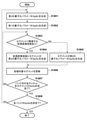
図18は、RAW画像をタイル分割した場合の、第2の量子化パラメータ(QpSb)の生成処理を示すシーケンス図である。 FIG. 18 is a sequence diagram showing a process of generating a second quantization parameter (QpSb) when the RAW image is tiled.
なお、本実施形態では、セグメントの分割は第1の変換係数を対象とし、第2の変換係数は、セグメントに含まれない。そして、第1の実施形態と同様の手順でセグメントの分割を行うことで、セグメントは第2の変換係数の有無によらず、第1の実施形態と同一となるものとする。 In this embodiment, the segment division targets the first conversion coefficient, and the second conversion coefficient is not included in the segment. Then, by dividing the segment by the same procedure as in the first embodiment, the segment becomes the same as in the first embodiment regardless of the presence or absence of the second conversion coefficient.
S1801において、量子化パラメータ生成部203は、各バンド(第1の処理単位)ごとに第3の量子化パラメータ(QpBr)を生成する。
In S1801, the quantization
S1802において、量子化パラメータ生成部203は、第2の処理単位であるセグメントごとのサブバンドデータの画質評価結果に応じて第3の量子化パラメータ(QpBr)を調整して第1の量子化パラメータ(QpBs)を生成する。
In S1802, the quantization
S1803において、量子化パラメータ生成部203は、セグメントに隣接する第2の変換係数が存在するかどうかについて判定を行う。
In S1803, the quantization
第2の変換係数が存在する場合(S1803で「YES」)、量子化パラメータ生成部203は処理をS1804に進め、存在しない場合には処理をステップS1805に進める。
If the second conversion coefficient is present (“YES” in S1803), the quantization
S1804にて、量子化パラメータ生成部203は、セグメントに含まれるサブバンドデータと、第2の変換係数の第2の量子化パラメータQpSbをQpBsから生成する。この詳細は、図19を用いて後述する。
In S1804, the quantization
また、ステップS1805に処理が進んだ場合、量子化パラメータ生成部203は、セグメントに含まれるサブバンドデータの第2の量子化パラメータQpSbをQpBsから生成する。ここでは、第1の実施形態と同様の方法で第3の量子化パラメータ(QpBr)、第2の量子化パラメータ(QpBs)、第1の量子化パラメータ(QpSb)を生成することとする。
Further, when the process proceeds to step S1805, the quantization
ただし、S1801においては、上端に存在する第2の変換係数やラインの左右に存在する第2の変換係数を、第一の処理単位に対応する目標符号量と発生符号量に含めて第3の量子化パラメータ(QpBr)を生成する構成を取っても良い。 However, in S1801, the second conversion coefficient existing at the upper end and the second conversion coefficient existing on the left and right of the line are included in the target code amount and the generated code amount corresponding to the first processing unit, and the third conversion coefficient is included. It may be configured to generate a quantization parameter (QpBr).
S1806にて、量子化パラメータ生成部203は、第2の量子化パラメータQpSb生成対象のセグメントを更新する。
In S1806, the quantization
S1807にて、量子化パラメータ生成部203は、バンド内の全チャネル、全セグメントの第2の量子化パラメータQpSb生成が完了したかどうかを判定する。そして、処理が完了していると判定した場合、量子化パラメータ生成部203は処理をS1808に進める。また、未完であると判定した場合には、量子化パラメータ生成部203は、処理をS1803に戻して、全チャネルの全セグメントの第2の量子化パラメータQpSbの生成が完了するまでセグメント単位の処理を繰り返す。
In S1807, the quantization
S1808にて、量子化パラメータ生成部203は、全バンドの処理が完了したかどうかを判定する。処理が完了していれば、量子化パラメータ生成部203は、本処理を終了する。また、未完である場合、量子化パラメータ生成部203は処理をS1801に戻し、全バンドの処理が完了するまでバンド単位の処理を繰り返す。
In S1808, the quantization
図19は、RAW画像を複数のタイルに分割し、着目タイルの上下左右に隣接するタイルが存在する場合の、上下左右の各第2の変換係数と、第1の量子化パラメータ(QpBs)の関係を、lev=1でサブバンド分割した場合のサブバンドを例に示している。 FIG. 19 shows a RAW image divided into a plurality of tiles, and when there are tiles adjacent to the tiles of interest on the top, bottom, left, and right, the second conversion coefficients on the top, bottom, left, and right, and the first quantization parameter (QpBs). The subband when the relationship is divided into subbands with lev = 1 is shown as an example.
ここでは、量子化パラメータ生成部203の説明のため、上、左の第2の変換係数は1係数、右、下の第2の変換係数は2係数の例を示している。
Here, for the sake of explanation of the quantization
図19を用いて、S1804の量子化パラメータ生成部203の処理を説明する。図示の点線で囲った第1の変換係数、第2の変換係数が、各々同じ第1の量子化パラメータ(QpBs)を参照していることを示している。
The processing of the quantization
量子化パラメータ生成部203は、例えば、第1の量子化パラメータQpBs[1,1]を参照するセグメントを対象に第2の量子化パラメータ(QpSb)を生成する場合、処理対象のセグメントに隣接する第2の変換係数が存在する。そのため、処理対象のセグメントに含まれる第1の係数のみならず、隣接、もしくは最近接する第2の変換係数の第2の量子化パラメータを、第1の量子化パラメータQpBs[1,1]を参照し、第1の実施形態と同様の方法で第2の量子化パラメータ(QpSb)を生成する。
For example, when the quantization
よって、処理対象のセグメントに含まれる第1の係数の第2の量子化パラメータと、隣接、もしくは最近接する第2の変換係数の第2の量子化パラメータは、同値となる。 Therefore, the second quantization parameter of the first coefficient included in the segment to be processed and the second quantization parameter of the second conversion coefficient adjacent to or closest to each other have the same value.
その他の第2の変換係数についても、処理対象のセグメントに隣接する第2の変換係数が存在する場合に、同様の方法で第2の量子化パラメータが生成される。 For the other second conversion coefficients, the second quantization parameter is generated in the same manner when there is a second conversion coefficient adjacent to the segment to be processed.
なお、図19では、第2の変換係数の数を1つ、もしくは2つの例を示したが、第2の変換係数がN(Nは定数)の場合についても同様の仕組みで第2の変換係数の第2の量子化パラメータ(QpSb)を生成可能である。 In FIG. 19, the number of the second conversion coefficients is one or two examples, but when the second conversion coefficient is N (N is a constant), the second conversion is performed by the same mechanism. It is possible to generate a second quantization parameter (QpSb) for the coefficients.
以上、符号化装置における量子化パラメータ生成部203の処理について説明してきたが、復号装置における量子化パラメータ生成部213についても同様に、セグメントに含まれる第1の変換係数とセグメントに最近接する第2の変換係数の第2の量子化を、同じ第1の量子化パラメータ(QpBs)を参照し、第1の実施形態と同様の方法で第2の量子化パラメータ(QpSb)を生成する。
Although the processing of the quantization
以上のようにすることで、RAW画像データを複数のタイルに分割し、タイル境界の劣化を抑えるために第2の変換係数を生成する場合に、第2の変換係数が存在しない場合と比較して量子化パラメータのデータ量を増やすことなくRAWデータを記録することが可能となる。 By doing so, when the RAW image data is divided into a plurality of tiles and the second conversion coefficient is generated in order to suppress the deterioration of the tile boundary, the case where the second conversion coefficient does not exist is compared with the case where the second conversion coefficient does not exist. Therefore, it is possible to record RAW data without increasing the amount of data of the quantization parameter.
[第4の実施形態]
以下、第4の実施形態について説明する。上記第3の実施形態では、RAW画像データを複数のタイルに分割、タイルごとに符号化する場合、量子化パラメータ生成部203は、第2の変換係数と、第2の変換係数に最近接する第1の変換係数の第2の量子化パラメータが同値になるように第2の量子化パラメータを生成した。このため、第2の変換係数の画質評価結果に応じた、第2の変換係数の量子化パラメータの調整が出来ないため、画質面で不利な構成であった。
[Fourth Embodiment]
Hereinafter, the fourth embodiment will be described. In the third embodiment, when the RAW image data is divided into a plurality of tiles and encoded for each tile, the quantization
第4の実施形態では、第3の実施形態の撮像装置に対して量子化パラメータ生成処理を工夫することで、第2の変換係数の画質評価結果に応じた第2の量子化パラメータの調整を可能としている。 In the fourth embodiment, by devising the quantization parameter generation process for the image pickup apparatus of the third embodiment, the second quantization parameter can be adjusted according to the image quality evaluation result of the second conversion coefficient. It is possible.
第3の実施形態と共通の構成の説明は省略し、以降では、本第4の実施形態における量子化パラメータ生成方法と、量子化パラメータ符号化方法の相違に係る構成について説明する。 The description of the configuration common to the third embodiment will be omitted, and the configuration relating to the difference between the quantization parameter generation method and the quantization parameter coding method in the fourth embodiment will be described below.
以下、第1の変換係数の評価および量子化パラメータを更新する第1の処理単位を第1のセグメントと定義し、第2の変換係数の評価および量子化パラメータを更新する第2の処理単位を第2のセグメントと定義する。 Hereinafter, the first processing unit for updating the evaluation and the quantization parameter of the first conversion coefficient is defined as the first segment, and the second processing unit for updating the evaluation and the quantization parameter of the second conversion coefficient is defined as the first segment. Defined as the second segment.
図20(a)は、RAW画像を上下にタイル分割した際の着目タイルの上側に隣接タイルが存在する場合の、各チャネルをlev=3でサブバンド分割した場合の画質制御に関わるサブバンドデータのうち、第2の変換係数の評価および量子化パラメータを更新する第2の処理単位(第2のセグメント)を示す。 FIG. 20A shows subband data related to image quality control when each channel is subbanded at lev = 3 when an adjacent tile exists above the tile of interest when the RAW image is vertically divided into tiles. Of these, a second processing unit (second segment) for evaluating the second conversion coefficient and updating the quantization parameter is shown.
上下にタイル分割し、上側に隣接タイルが存在する場合、第2の変換係数は第1の変換係数の上にライン単位で存在する。 When the tiles are divided into upper and lower tiles and the adjacent tiles are present on the upper side, the second conversion coefficient exists on the first conversion coefficient in line units.
ここでは、量子化パラメータ生成部203の説明のため、3LH、3HHのサブバンドで第2の変換係数は1係数が、2LH、2HH、1LH、1HHのサブバンドで第2の変換係数は2係数が存在した場合の例を示している。
Here, for the explanation of the quantization
各第2のセグメントは、全チャネルのレベル3のサブバンド{3LL,3HL,3LH,3HH}の水平、垂直方向それぞれに1×{第2の変換係数のライン数}、レベル2のサブバンド{2HL,2LH,2HH}の水平、垂直方向にそれぞれ2×{第2の変換係数のライン数}、レベル1のサブバンド{1HL,1LH,1HH}の水平、垂直方向にそれぞれ4×{第2の変換係数のライン数}としている。
Each second segment is a
量子化パラメータ生成部203は、初期量子化パラメータQpBr(0)を、第2のセグメントごとの画質特性に応じて修正することで、第2のセグメントごとの第4の量子化パラメータ(QpBs’)を生成する。
The quantization
図20(b)は、第4の量子化パラメータ(QpBs‘)とサブバンドデータ(第2の変換係数)との関係を示す。ここに示すように、1つのセグメントに含まれる各チャネルの複数のサブバンドデータ(変換係数)に対して1つの第4の量子化パラメータ(QpBs’)が生成されており、垂直方向は第1の実施形態の図6(b)とは異なり、上端、もしくは下端に1つの第4の量子化パラメータ(QpBs’)を固定で持つことになる。 FIG. 20 (b) shows the relationship between the fourth quantization parameter (QpBs') and the subband data (second conversion coefficient). As shown here, one fourth quantization parameter (QpBs') is generated for a plurality of subband data (conversion coefficients) of each channel contained in one segment, and the vertical direction is the first. Unlike FIG. 6 (b) of the embodiment, one fourth quantization parameter (QpBs') is fixedly held at the upper end or the lower end.
以上のように、図20(a)、図(b)では、上端に隣接タイルが存在する場合について説明したが、下端に隣接タイルが存在する場合は、以下の通りに処理を行う。 As described above, in FIGS. 20 (a) and 20 (b), the case where the adjacent tile exists at the upper end has been described, but when the adjacent tile exists at the lower end, the processing is performed as follows.
各第2のセグメントは、上端に隣接タイルが存在する場合と同様である。量子化パラメータ生成部203は、第1の変換係数の最終ラインの第3の量子化パラメータ(QpBr)を、第2のセグメントごとの画質特性に応じて修正し、第2のセグメントごとの第4の量子化パラメータ(QpBs’)を生成する。
Each second segment is the same as if there were adjacent tiles at the top. The quantization
量子化パラメータ生成部203は、第2のセグメントごとの画質特性については、各第2のセグメントに含まれる第2の変換係数のうち、例えば3LLのサブバンドデータを低周波成分として評価し、1HL,1LH,1HHのサブバンドデータから高周波成分を評価する。なお、第2のセグメント内に評価対象の各サブバンドデータ(第2の変換係数)が複数存在する場合は、その平均値をもって評価する。そして、第1の実施形態と同様に、量子化パラメータ生成部203は、低周波成分の振幅が小さい程量子化を細かく、高周波成分の振幅が大きい程量子化を粗く制御するように、第3の量子化パラメータ(QpBr)に対してゲイン、オフセット調整を行う。
Regarding the image quality characteristics for each second segment, the quantization
図21(a)は、RAW画像データを左右にタイル分割し、左側に隣接タイルが存在する場合の、各チャネルをlev=3でサブバンド分割した場合の画質制御に関わるサブバンドデータのうち、第2の変換係数の評価および量子化パラメータを更新する第2の処理単位(第2のセグメント)を示す。 FIG. 21A shows subband data related to image quality control when the RAW image data is tiled left and right and the adjacent tiles are present on the left side and each channel is subbanded at lev = 3. The second processing unit (second segment) which evaluates the second conversion coefficient and updates the quantization parameter is shown.
左右にタイル分割し、左端に隣接タイルが存在する場合、第2の変換係数は第1の変換係数の左に垂直ライン単位で存在することになる。 If the tiles are divided into left and right and the adjacent tile exists at the left end, the second conversion coefficient exists in units of vertical lines to the left of the first conversion coefficient.
ここでは、量子化パラメータ生成部203の説明のため、3HL、3HHのサブバンドで第2の変換係数は1係数、2HL、2HH、1HL、1HHのサブバンドで第2の変換係数は2係数存在した場合の例を示している。
Here, for the explanation of the quantization
各第2のセグメントは、全チャネルのレベル3のサブバンド{3LL,3HL,3LH,3HH}の水平、垂直方向それぞれに「水平方向の第2の変換係数の数」×1、レベル2のサブバンド{2HL,2LH,2HH}の水平、垂直方向にそれぞれを「水平方向の第2の変換係数の数」×1、レベル1のサブバンド{1HL,1LH,1HH}の水平、垂直方向にそれぞれ「水平方向の第2の変換係数の数」×1としている。
Each second segment is a
量子化パラメータ生成部203は、量子化パラメータQpBrを、第2のセグメントごとの画質特性に応じて修正することで、第2のセグメントごとの第4の量子化パラメータ(QpBs’)を生成する。第2のセグメントごとの画質特性に応じた修正方法は、図20(b)で説明した方法と同様とする。
The quantization
図21(b)は、第4の量子化パラメータ(QpBs’)とサブバンドデータ(第2の変換係数)との関係を示す。ここに示すように、1つのセグメントに含まれる各チャネルの複数のサブバンドデータ(第2の変換係数)に対して4つの第4の量子化パラメータ(QpBs’)が生成されており、垂直方向は第1の実施形態の図6(b)と同様の関係となっている。 FIG. 21B shows the relationship between the fourth quantization parameter (QpBs') and the subband data (second conversion coefficient). As shown here, four fourth quantization parameters (QpBs') are generated for a plurality of subband data (second conversion coefficients) of each channel contained in one segment, and are in the vertical direction. Has the same relationship as in FIG. 6 (b) of the first embodiment.
レベル1における4つのQpBs’から、各レベルのQpLv1~QpLv3の算出方法については、第2の実施形態に記載の、前述の式(6)を参照することとし、ここでの説明は省略する。
For the calculation method of QpLv1 to QpLv3 of each level from the four QpBs' in
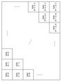
図22Aは、RAW画像を複数に分割し、上下左右に隣接するタイルが存在する場合の、上下左右の各第2の変換係数と、第1の量子化パラメータ(QpBs)、第4の量子化パラメータ(QpBs‘)の関係を、lev=1のサブバンドを例に示している。ここでは、量子化パラメータ生成部203の説明のため、図19と同様に、上、左の第2の変換係数は1係数、右、下の第2の変換係数は2係数の例を示す。前述した第2のセグメントの定義に従い、各第2の変換係数は、各々の第2のセグメント含まれている。第2のセグメントは、第1のセグメントに対して、隣接タイルがある方向(この場合、上下左右)に、1つずつ存在する。
FIG. 22A shows a RAW image divided into a plurality of parts, and when there are adjacent tiles on the top, bottom, left, and right, the second conversion coefficient for each of the top, bottom, left, and right, the first quantization parameter (QpBs), and the fourth quantization. The relationship of the parameters (QpBs') is shown by taking a subband of lev = 1 as an example. Here, for the sake of explanation of the quantization
また、第2のセグメントごとの第4の量子化パラメータ(QpBs‘)も同様に、第1のセグメントに対応した第1の量子化パラメータ(QpBs)に対して、隣接タイルがある方向(この場合、上下左右)に、1つずつ存在する。 Similarly, the fourth quantization parameter (QpBs') for each second segment also has tiles adjacent to the first quantization parameter (QpBs) corresponding to the first segment (in this case, in this case). , Up, down, left and right), one at a time.
量子化パラメータ生成部203は、第2のセグメントに含まれる、各チャネル、各サブバンド個別の第5の量子化パラメータ(QpSb’)を、第4の量子化パラメータ(QpBs’)を参照して算出する。
The quantization
次式(7)は、第5の量子化パラメータ(QpSb‘)生成のための計算式である。
QpSb’[i][j]=QpBs’×α[i][j]+β[i][j] …(7)
QpSb‘:各チャネル、各サブバンド個別の第5の量子化パラメータ
QpBs‘:全チャネル、全サブバンド共通の第4の量子化パラメータ
α:傾き
β:切片
i:チャネルインデックス(0~3)
j:サブバンドインデックス(0~9)
第2の量子化パラメータ算出のための式(5)に対して、参照する量子化パラメータを第4の量子化パラメータ(QpBs‘)に変更したのみであるため、詳細な説明はここでは省略する。
The following equation (7) is a calculation equation for generating the fifth quantization parameter (QpSb').
QpSb'[i] [j] = QpBs' × α [i] [j] + β [i] [j]… (7)
QpSb': Fifth quantization parameter for each channel and each subband
QpBs': Fourth quantization parameter common to all channels and all subbands α: Slope β: Intercept
i: Channel index (0-3)
j: Subband index (0-9)
Since the reference quantization parameter is only changed to the fourth quantization parameter (QpBs') with respect to the equation (5) for calculating the second quantization parameter, detailed description thereof is omitted here. ..
量子化パラメータ符号化部206は、第1の量子化パラメータ(QpBs)および、第4の量子化パラメータ(QpBs‘)を混在させて符号化し、対応するセグメントの座標位置に対してラスター順に第2の量子化パラメータ(QpBs)および、第4の量子化パラメータ(QpBs‘)を入力し、符号化する。
The quantization
図22Aの例では、以下の順で第1の量子化パラメータ(QpBs)および、第4の量子化パラメータ(QpBs‘)を量子化パラメータ符号化部206に入力することになる。
QpBs‘[0,0]、QpBs‘[0,1]・・・QpBs‘[0、P+1]、
QpBs‘[1,0]、QpBs[0,1]・・・QpBs‘[1、P+1]、
・・・
QpBs‘[Q,0]、QpBs[Q,1]・・・QpBs‘[Q、P+1]
QpBs‘[Q+1,0]、QpBs’[Q+1,1]・・・QpBs‘[Q+1、P+1]
In the example of FIG. 22A, the first quantization parameter (QpBs) and the fourth quantization parameter (QpBs') are input to the quantization
QpBs'[0,0], QpBs' [0,1] ... QpBs' [0, P + 1],
QpBs'[1,0], QpBs [0,1] ... QpBs' [1, P + 1],
・ ・ ・
QpBs'[Q,0], QpBs [Q,1] ... QpBs' [Q, P + 1]
QpBs'[Q + 1,0], QpBs' [Q + 1,1] ... QpBs' [Q + 1, P + 1]
図22B(a)及び図22B(b)は、第2のセグメントと第4の量子化パラメータ(QpBs‘)の関係を示している。 22B (a) and 22B (b) show the relationship between the second segment and the fourth quantization parameter (QpBs').
図22B(a)は、上端タイル境界近辺の第2のセグメントと第4の量子化パラメータ(QpBs‘)の関係を示している。第2のセグメントに含まれる第2の変換係数は、各々、第2のセグメントに対応した第4のパラメータ(QpBs‘)を参照する。 FIG. 22B (a) shows the relationship between the second segment near the uppermost tile boundary and the fourth quantization parameter (QpBs'). The second conversion coefficient included in the second segment refers to the fourth parameter (QpBs') corresponding to the second segment, respectively.
図22B(b)は、下端タイル境界近辺の第2のセグメントと第4の量子化パラメータ(QpBs‘)の関係を示しており、上端タイル境界近辺と同様の関係に第2のセグメントに含まれる第2の変換係数は、各々、第2のセグメントに対応した第4のパラメータ(QpBs‘)を参照する。 FIG. 22B (b) shows the relationship between the second segment near the lower end tile boundary and the fourth quantization parameter (QpBs'), and is included in the second segment in the same relationship as near the upper end tile boundary. The second conversion coefficient refers to the fourth parameter (QpBs') corresponding to the second segment, respectively.
以上、符号化装置における量子化パラメータ生成部203の処理について説明してきた。復号装置においては、以下の処理を行うことになる。
The processing of the quantization
量子化パラメータ復号部212は、メモリ105から入力された符号化データに含まれる、第1の量子化パラメータと第4の量子化パラメータを復号する。量子化パラメータ生成部213は、復号された第1の量子化パラメータを用いて、第1の変換係数を逆量子化で生成する際に使用する第2の量子化パラメータを生成し、復号された第4の量子化パラメータを用いて、第2の変換係数を逆量子化で生成する際に使用する第5の量子化パラメータを生成する。逆量子化部214は、復号部211から出力された量子化済み第1の変換係数を第2の量子化パラメータを用いて逆量子化処理し、量子化済み第2の変換係数を第5の量子化パラメータを用いて逆量子化する。周波数逆変換部215は、第1の変換係数と第2の変換係数を入力して離散ウェーブレット逆変換による周波数変換処理を行い、所定の分割レベルのサブバンドデータ(変換係数)からチャネルを復元する。
The quantization
また、チャネル逆変換部216は、周波数逆変換部215からのデータを入力し、タイル単位のベイヤ配列のRAW画像データを生成する。そして、タイル統合部2302は、各タイルを接続し、1フレームのRAW画像データを生成し、出力する。
Further, the channel
以上のようにすることで、第2のセグメントに対応した第4の量子化パラメータ(QpBs‘)を生成し符号化することで、第2の変換係数の量子化パラメータを、第2のセグメントごとの画質特性に応じて修正することができるため、僅かな量子化パラメータ符号量の増加で、より高品位のRAWデータを記録することが可能となる。 By doing the above, by generating and encoding the fourth quantization parameter (QpBs') corresponding to the second segment, the quantization parameter of the second conversion coefficient can be set for each second segment. Since it can be modified according to the image quality characteristics of the above, it is possible to record higher quality RAW data with a slight increase in the amount of quantization parameter code.
(その他の実施例)
本発明は、上述の実施形態の1以上の機能を実現するプログラムを、ネットワーク又は記憶媒体を介してシステム又は装置に供給し、そのシステム又は装置のコンピュータにおける1つ以上のプロセッサーがプログラムを読出し実行する処理でも実現可能である。また、1以上の機能を実現する回路(例えば、ASIC)によっても実現可能である。
(Other examples)
The present invention supplies a program that realizes one or more functions of the above-described embodiment to a system or device via a network or storage medium, and one or more processors in the computer of the system or device reads and executes the program. It can also be realized by the processing to be performed. It can also be realized by a circuit (for example, ASIC) that realizes one or more functions.
100…撮像装置、101…制御部、102…撮像部、103…RAWデータ符号化・復号部、104…メモリI/F部、105…メモリ、106…記録処理部、107…記録媒体、201…チャネル変換部、202…周波数変換部、203…量子化パラメータ生成部、204…量子化部、205…符号化部、206…量子化パラメータ符号化部、2301…タイル分割部、2302…タイル統合部 100 ... Imaging device, 101 ... Control unit, 102 ... Imaging unit, 103 ... RAW data coding / decoding unit, 104 ... Memory I / F unit, 105 ... Memory, 106 ... Recording processing unit, 107 ... Recording medium, 201 ... Channel conversion unit, 202 ... Frequency conversion unit, 203 ... Quantization parameter generation unit, 204 ... Quantization unit, 205 ... Coding unit, 206 ... Quantization parameter coding unit, 2301 ... Tile division unit, 2302 ... Tile integration unit
Claims (16)
符号化対象のRAW画像データを複数のタイルに分割する分割手段と、
該分割手段により分割された前記複数のタイル毎に互いに異なる成分を持つ複数のチャネルのプレーンを生成する生成手段と、
該生成手段で生成した各チャネルのプレーンに対して周波数変換し、複数の分解レベルのサブバンドデータを生成する変換手段と、
前記RAW画像データの同じ領域に対応する複数のセグメントに分割するために、前記複数のサブバンドデータをそれぞれ同じ数のセグメントに分割し、セグメント毎に複数のサブバンドデータで共通となる第1の量子化パラメータを決定する制御手段と、
前記制御手段により決定された第1の量子化パラメータに基づいて、前記変換手段で得たサブバンドデータをセグメント毎にそれぞれ量子化する量子化手段と、
前記量子化により得られた量子化結果を、サブバンド毎に符号化する符号化手段と、
を有し、
前記生成手段は、
着目タイルから前記複数のチャネルのプレーンを生成する際に、前記着目タイルと、前記着目タイルの隣接タイル内の前記着目タイルとの境界から所定の距離までのデータとから、前記複数のチャネルのプレーンを生成し、
前記制御手段は、
前記着目タイルのサブバンドデータを前記複数のセグメントに分割して前記第1の量子化パラメータを決定し、前記隣接タイルのサブバンドデータは、前記着目タイルとの境界を介して隣接するセグメントの量子化パラメータを適応する
ことを特徴とする画像符号化装置。 A coding device that encodes RAW image data of a Bayer array.
A dividing means for dividing the RAW image data to be encoded into a plurality of tiles, and
A generation means for generating a plane of a plurality of channels having different components for each of the plurality of tiles divided by the division means, and a generation means.
A conversion means that frequency-converts the plane of each channel generated by the generation means to generate subband data of a plurality of decomposition levels, and a conversion means.
In order to divide the RAW image data into a plurality of segments corresponding to the same region, the plurality of subband data are each divided into the same number of segments, and each segment is common to the plurality of subband data. Control means to determine the quantization parameters and
A quantization means that quantizes the subband data obtained by the conversion means for each segment based on the first quantization parameter determined by the control means, and
A coding means for encoding the quantization result obtained by the above-mentioned quantization for each subband,
Have,
The generation means is
When generating the planes of the plurality of channels from the tiles of interest, the planes of the plurality of channels are obtained from the data from the boundary between the tiles of interest and the tiles of interest in the adjacent tiles of the tiles of interest to a predetermined distance. To generate,
The control means is
The subband data of the tile of interest is divided into the plurality of segments to determine the first quantization parameter, and the subband data of the adjacent tile is the quantum of the adjacent segment via the boundary with the tile of interest. An image coding device characterized by adapting the quantization parameters.
前記量子化手段は、前記第2の量子化パラメータに基づいて、前記複数のサブバンドデータのセグメントをそれぞれ量子化することを特徴とする請求項1に記載の画像符号化装置。 The control means determines a second quantization parameter corresponding to each of the plurality of subband data based on the first quantization parameter.
The image coding apparatus according to claim 1, wherein the quantization means quantizes each of the plurality of subband data segments based on the second quantization parameter.
前記距離は、前記ウェーブレット変換の実行回数に応じた距離であることを特徴とする請求項1に記載の画像符号化装置。 The transform means performs a wavelet transform and
The image coding apparatus according to claim 1, wherein the distance is a distance corresponding to the number of times the wavelet transform is executed.
符号化データから、復号しようとする着目タイル内の各セグメントの第1の量子化パラメータを復号する第1の復号手段と、
前記符号化データから、前記着目タイルの各セグメントの量子化後のデータを復号する第2の復号手段と、
前記第2の復号手段で得た量子化後のデータを前記第1の量子化パラメータに従って逆量子化する逆量子化手段と、
該逆量子化手段で得た各セグメントで構成されるデータを周波数逆変換を行うことで、着目タイルの複数のチャネルのプレーンを生成する逆変換手段と、
複数のチャネルのプレーンから、着目タイルのRAW画像データを生成する生成手段と、
該生成手段で得た各タイルのRAW画像データを統合して1枚のベイヤ配列のRAW画像データを生成する統合手段と
を有することを特徴とする画像復号装置。 An image decoding device that decodes the coded data generated by the image coding device according to claim 1.
A first decoding means for decoding the first quantization parameter of each segment in the tile of interest to be decoded from the encoded data,
A second decoding means for decoding the quantized data of each segment of the tile of interest from the coded data,
A dequantization means that dequantizes the quantized data obtained by the second decoding means according to the first quantization parameter, and a dequantization means.
An inverse conversion means for generating a plane of a plurality of channels of the tile of interest by performing frequency inverse conversion on the data composed of each segment obtained by the inverse quantization means.
A generation method for generating RAW image data of the tile of interest from planes of multiple channels,
An image decoding apparatus comprising: an integrated means for integrating RAW image data of each tile obtained by the generation means to generate RAW image data of one Bayer array.
符号化対象のRAW画像データを複数のタイルに分割する分割工程と、
該分割工程により分割された前記複数のタイル毎に互いに異なる成分を持つ複数のチャネルのプレーンを生成する生成工程と、
該生成工程で生成した各チャネルのプレーンに対して周波数変換し、複数の分解レベルのサブバンドデータを生成する変換工程と、
前記RAW画像データの同じ領域に対応する複数のセグメントに分割するために、前記複数のサブバンドデータをそれぞれ同じ数のセグメントに分割し、セグメント毎に複数のサブバンドデータで共通となる第1の量子化パラメータを決定する制御工程と、
前記制御工程により決定された第1の量子化パラメータに基づいて、前記変換工程で得たサブバンドデータをセグメント毎にそれぞれ量子化する量子化工程と、
前記量子化により得られた量子化結果を、サブバンド毎に符号化する符号化工程と、
を有し、
前記生成工程は、
着目タイルから前記複数のチャネルのプレーンを生成する際に、前記着目タイルと、前記着目タイルの隣接タイル内の前記着目タイルとの境界から所定の距離までのデータとから、前記複数のチャネルのプレーンを生成し、
前記制御工程は、
前記着目タイルのサブバンドデータを前記複数のセグメントに分割して前記第1の量子化パラメータを決定し、前記隣接タイルのサブバンドデータは、前記着目タイルとの境界を介して隣接するセグメントの量子化パラメータを適応する
ことを特徴とする画像符号化装置の制御方法。 It is a control method of a coding device that encodes RAW image data of a Bayer array.
A division process that divides the RAW image data to be encoded into multiple tiles, and
A generation step of generating a plane of a plurality of channels having different components from each of the plurality of tiles divided by the division step, and a generation step of generating the planes of a plurality of channels.
A conversion step of frequency-converting the plane of each channel generated in the generation step to generate subband data of a plurality of decomposition levels, and a conversion step.
In order to divide the RAW image data into a plurality of segments corresponding to the same region, the plurality of subband data are each divided into the same number of segments, and each segment is common to the plurality of subband data. The control process that determines the quantization parameters and
A quantization step in which the subband data obtained in the conversion step is quantized for each segment based on the first quantization parameter determined by the control step, and
A coding step of coding the quantization result obtained by the above-mentioned quantization for each subband,
Have,
The production step is
When generating the planes of the plurality of channels from the tiles of interest, the planes of the plurality of channels are obtained from the data from the boundary between the tiles of interest and the tiles of interest in the adjacent tiles of the tiles of interest to a predetermined distance. To generate,
The control step is
The subband data of the tile of interest is divided into the plurality of segments to determine the first quantization parameter, and the subband data of the adjacent tile is the quantum of the adjacent segment via the boundary with the tile of interest. A control method for an image coding device, characterized in that the conversion parameters are applied.
符号化データから、復号しようとする着目タイル内の各セグメントの第1の量子化パラメータを復号する第1の復号工程と、
前記符号化データから、前記着目タイルの各セグメントの量子化後のデータを復号する第2の復号工程と、
前記第2の復号工程で得た量子化後のデータを前記第1の量子化パラメータに従って逆量子化する逆量子化工程と、
該逆量子化工程で得た各セグメントで構成されるデータを周波数逆変換を行うことで、着目タイルの複数のチャネルのプレーンを生成する逆変換工程と、
複数のチャネルのプレーンから、着目タイルのRAW画像データを生成する生成工程と、
該生成工程で得た各タイルのRAW画像データを統合して1枚のベイヤ配列のRAW画像データを生成する統合工程と
を有することを特徴とする画像復号装置の制御方法。 A control method for an image decoding device that decodes coded data generated by the image coding device according to claim 1.
A first decoding step of decoding the first quantization parameter of each segment in the tile of interest to be decoded from the coded data,
A second decoding step of decoding the quantized data of each segment of the tile of interest from the coded data,
A dequantization step of dequantizing the quantized data obtained in the second decoding step according to the first quantization parameter, and a dequantization step.
A reverse conversion step of generating planes of a plurality of channels of the tile of interest by performing frequency reverse conversion of the data composed of each segment obtained in the reverse quantization step.
The generation process to generate RAW image data of the tile of interest from the planes of multiple channels,
A control method for an image decoding apparatus, which comprises an integration step of integrating RAW image data of each tile obtained in the generation step to generate RAW image data of one Bayer array.
Priority Applications (2)
| Application Number | Priority Date | Filing Date | Title |
|---|---|---|---|
| JP2018114689A JP7033013B2 (en) | 2018-06-15 | 2018-06-15 | Image coding device, image decoding device, their control method, and program |
| US16/430,824 US11140392B2 (en) | 2018-06-15 | 2019-06-04 | Image encoding apparatus, image decoding apparatus, control methods thereof, and non- transitory computer-readable storage medium |
Applications Claiming Priority (1)
| Application Number | Priority Date | Filing Date | Title |
|---|---|---|---|
| JP2018114689A JP7033013B2 (en) | 2018-06-15 | 2018-06-15 | Image coding device, image decoding device, their control method, and program |
Publications (3)
| Publication Number | Publication Date |
|---|---|
| JP2019220754A JP2019220754A (en) | 2019-12-26 |
| JP2019220754A5 JP2019220754A5 (en) | 2021-07-26 |
| JP7033013B2 true JP7033013B2 (en) | 2022-03-09 |
Family
ID=68839339
Family Applications (1)
| Application Number | Title | Priority Date | Filing Date |
|---|---|---|---|
| JP2018114689A Active JP7033013B2 (en) | 2018-06-15 | 2018-06-15 | Image coding device, image decoding device, their control method, and program |
Country Status (2)
| Country | Link |
|---|---|
| US (1) | US11140392B2 (en) |
| JP (1) | JP7033013B2 (en) |
Families Citing this family (2)
| Publication number | Priority date | Publication date | Assignee | Title |
|---|---|---|---|---|
| EP3550825A4 (en) * | 2016-12-01 | 2020-05-13 | LG Electronics Inc. -1- | Image display device and image display system comprising same |
| CN115984296B (en) * | 2023-03-21 | 2023-06-13 | 译企科技(成都)有限公司 | Medical image segmentation method and system applying multi-attention mechanism |
Citations (3)
| Publication number | Priority date | Publication date | Assignee | Title |
|---|---|---|---|---|
| JP2005150846A (en) | 2003-11-11 | 2005-06-09 | Canon Inc | Image processing method and apparatus thereof |
| JP2013138361A (en) | 2011-12-28 | 2013-07-11 | Canon Inc | Image encoding apparatus, image encoding method, and program |
| JP2018033044A (en) | 2016-08-25 | 2018-03-01 | キヤノン株式会社 | Image encoder and control method and program thereof |
Family Cites Families (6)
| Publication number | Priority date | Publication date | Assignee | Title |
|---|---|---|---|---|
| US6154493A (en) | 1998-05-21 | 2000-11-28 | Intel Corporation | Compression of color images based on a 2-dimensional discrete wavelet transform yielding a perceptually lossless image |
| US8363717B2 (en) | 2005-05-17 | 2013-01-29 | Canon Kabushiki Kaisha | Image processing apparatus |
| US9749630B2 (en) * | 2010-09-30 | 2017-08-29 | Sun Patent Trust | Image decoding method, image coding method, image decoding apparatus, image coding apparatus, program, and integrated circuit |
| JP5947641B2 (en) | 2012-07-06 | 2016-07-06 | キヤノン株式会社 | Moving picture coding apparatus, control method therefor, and computer program |
| JP6722995B2 (en) | 2015-10-23 | 2020-07-15 | キヤノン株式会社 | Encoding method, encoding device, imaging device, and program |
| US10356408B2 (en) * | 2015-11-27 | 2019-07-16 | Canon Kabushiki Kaisha | Image encoding apparatus and method of controlling the same |
-
2018
- 2018-06-15 JP JP2018114689A patent/JP7033013B2/en active Active
-
2019
- 2019-06-04 US US16/430,824 patent/US11140392B2/en active Active
Patent Citations (3)
| Publication number | Priority date | Publication date | Assignee | Title |
|---|---|---|---|---|
| JP2005150846A (en) | 2003-11-11 | 2005-06-09 | Canon Inc | Image processing method and apparatus thereof |
| JP2013138361A (en) | 2011-12-28 | 2013-07-11 | Canon Inc | Image encoding apparatus, image encoding method, and program |
| JP2018033044A (en) | 2016-08-25 | 2018-03-01 | キヤノン株式会社 | Image encoder and control method and program thereof |
Also Published As
| Publication number | Publication date |
|---|---|
| JP2019220754A (en) | 2019-12-26 |
| US20190387228A1 (en) | 2019-12-19 |
| US11140392B2 (en) | 2021-10-05 |
Similar Documents
| Publication | Publication Date | Title |
|---|---|---|
| JP6986868B2 (en) | Image coding device, image decoding device, image coding method, image decoding method, program | |
| US20210136394A1 (en) | Encoding apparatus and encoding method, and decoding apparatus and decoding method | |
| JP2006014121A (en) | Image encoding method, image encoding apparatus, and imaging apparatus | |
| JP6857973B2 (en) | Image coding device and its control method | |
| JP7033013B2 (en) | Image coding device, image decoding device, their control method, and program | |
| US9531915B2 (en) | Image encoding system and method thereof | |
| JP6857970B2 (en) | Image coding device and its control method | |
| JP4449400B2 (en) | Image encoding apparatus and method, program, and recording medium | |
| JP7001383B2 (en) | Coding device, coding method, and program | |
| EP1322116A2 (en) | Image compression device, method for image compression, and electronic camera | |
| JP4315928B2 (en) | Image processing apparatus and image processing method | |
| JP6465570B2 (en) | IMAGING DEVICE AND IMAGING DEVICE CONTROL METHOD | |
| JP6849359B2 (en) | Coding device, coding device control method, and program | |
| JP7321237B2 (en) | Image encoding device, image encoding method, program | |
| JP6632752B2 (en) | Image encoding apparatus and method, program and storage medium | |
| JP6465571B2 (en) | IMAGING DEVICE AND IMAGING DEVICE CONTROL METHOD | |
| JP6813991B2 (en) | Image coding device and its control method and program | |
| JP6875817B2 (en) | Image processing equipment, imaging equipment, image processing methods and programs | |
| JP6775339B2 (en) | Image coding device and its control method | |
| JP6806466B2 (en) | Image coding device and its control method | |
| JP2001231009A (en) | Image data storage device ad method | |
| JP7465073B2 (en) | Image encoding device, control method and program thereof | |
| JP6497981B2 (en) | Image coding apparatus and control method thereof | |
| JP2021069059A (en) | Image processing device and image processing method | |
| JP2008124969A (en) | Lossless image coding method and lossless image coding apparatus |
Legal Events
| Date | Code | Title | Description |
|---|---|---|---|
| A521 | Request for written amendment filed |
Free format text: JAPANESE INTERMEDIATE CODE: A523 Effective date: 20180620 |
|
| RD01 | Notification of change of attorney |
Free format text: JAPANESE INTERMEDIATE CODE: A7421 Effective date: 20210103 |
|
| A521 | Request for written amendment filed |
Free format text: JAPANESE INTERMEDIATE CODE: A523 Effective date: 20210113 |
|
| A521 | Request for written amendment filed |
Free format text: JAPANESE INTERMEDIATE CODE: A523 Effective date: 20210528 |
|
| A621 | Written request for application examination |
Free format text: JAPANESE INTERMEDIATE CODE: A621 Effective date: 20210528 |
|
| A977 | Report on retrieval |
Free format text: JAPANESE INTERMEDIATE CODE: A971007 Effective date: 20220114 |
|
| TRDD | Decision of grant or rejection written | ||
| A01 | Written decision to grant a patent or to grant a registration (utility model) |
Free format text: JAPANESE INTERMEDIATE CODE: A01 Effective date: 20220128 |
|
| A61 | First payment of annual fees (during grant procedure) |
Free format text: JAPANESE INTERMEDIATE CODE: A61 Effective date: 20220225 |
|
| R151 | Written notification of patent or utility model registration |
Ref document number: 7033013 Country of ref document: JP Free format text: JAPANESE INTERMEDIATE CODE: R151 |