JP4449400B2 - Image encoding apparatus and method, program, and recording medium - Google Patents
Image encoding apparatus and method, program, and recording medium Download PDFInfo
- Publication number
- JP4449400B2 JP4449400B2 JP2003351392A JP2003351392A JP4449400B2 JP 4449400 B2 JP4449400 B2 JP 4449400B2 JP 2003351392 A JP2003351392 A JP 2003351392A JP 2003351392 A JP2003351392 A JP 2003351392A JP 4449400 B2 JP4449400 B2 JP 4449400B2
- Authority
- JP
- Japan
- Prior art keywords
- encoding
- bit
- code
- encoding target
- generating
- Prior art date
- Legal status (The legal status is an assumption and is not a legal conclusion. Google has not performed a legal analysis and makes no representation as to the accuracy of the status listed.)
- Expired - Fee Related
Links
Images
Classifications
-
- G—PHYSICS
- G06—COMPUTING; CALCULATING OR COUNTING
- G06T—IMAGE DATA PROCESSING OR GENERATION, IN GENERAL
- G06T9/00—Image coding
- G06T9/004—Predictors, e.g. intraframe, interframe coding
Description
本発明は、例えばJPEG−2000方式のように、ウェーブレット変換とエントロピー符号化とにより画像を圧縮する画像符号化装置及びその方法、並びに画像符号化処理をコンピュータに実行させるプログラム及びそのプログラムが記録された記録媒体に関する。 The present invention records, for example, an image encoding apparatus and method for compressing an image by wavelet transform and entropy encoding as in the JPEG-2000 system, a program for causing a computer to execute image encoding processing, and the program. The present invention relates to a recording medium.
従来の代表的な画像圧縮方式として、ISO(International Standards Organization)によって標準化されたJPEG(Joint Photographic Experts Group)方式がある。これは、離散コサイン変換(DCT:Descrete Cosine Transform)を用い、比較的高いビットが割り当てられる場合には、良好な符号化画像及び復号画像を供することが知られている。しかし、ある程度以上に符号化ビット数を少なくすると、DCT特有のブロック歪みが顕著になり、主観的に劣化が目立つようになる。 As a conventional typical image compression method, there is a JPEG (Joint Photographic Experts Group) method standardized by ISO (International Standards Organization). This is known to use a discrete cosine transform (DCT) and provide a good encoded image and decoded image when relatively high bits are assigned. However, if the number of encoded bits is reduced to a certain degree, block distortion peculiar to DCT becomes remarkable, and deterioration becomes conspicuous subjectively.
一方、近年では画像をフィルタバンクと呼ばれるハイパス・フィルタとローパス・フィルタとを組み合わせたフィルタによって複数の帯域に分割し、各帯域毎に符号化を行う方式の研究が盛んになっている。その中でも、ウェーブレット変換符号化は、DCTのように高圧縮でブロック歪みが顕著になるという欠点がないことから、DCTに代わる新たな技術として有力視されている。 On the other hand, in recent years, research on a method in which an image is divided into a plurality of bands by a filter combining a high-pass filter and a low-pass filter called a filter bank and coding is performed for each band has been actively conducted. Among them, wavelet transform coding is regarded as a promising new technology to replace DCT because it does not have the disadvantage that block distortion becomes remarkable due to high compression unlike DCT.
2001年1月に国際標準化が完了したJPEG−2000方式は、このウェーブレット変換に高能率なエントロピー符号化(ビットプレーン単位のビット・モデリングと算術符号化)を組み合わせた方式を採用しており、JPEGに比べて符号化効率の大きな改善を実現している。 The JPEG-2000 system, whose international standardization was completed in January 2001, employs a system that combines this wavelet transform with highly efficient entropy coding (bit modeling and arithmetic coding in units of bit planes). Compared to this, the coding efficiency is greatly improved.
これらの国際規格ではデコーダ側の規格のみが定められており、エンコーダ側は自由に設計することができる。その反面、目標の圧縮率を実現する効果的なレート制御手法についての規格が存在しないため、ノウハウの確立が何よりも重要になる。 In these international standards, only the standard on the decoder side is defined, and the encoder side can be designed freely. On the other hand, since there is no standard for an effective rate control method that achieves the target compression rate, the establishment of know-how is most important.
特にJPEG方式では、このレート制御が困難であり、目標値を得るまでに複数回の符号化を施す必要も多々あった。しかしながら、これは処理時間の増大に繋がるため、JPEG−2000方式では、1度の符号化で目標の符号量を得ることが望まれている。 In particular, in the JPEG method, this rate control is difficult, and it is often necessary to perform encoding a plurality of times before obtaining the target value. However, since this leads to an increase in processing time, in the JPEG-2000 system, it is desired to obtain a target code amount by one encoding.
ここで、JPEG−2000方式では、RD(Rate-Distortion)特性を利用したレート制御手法が一般的に用いられているが、このレート制御手法は、汎用性があるものの非常に計算負荷が高いという欠点があった。 Here, in the JPEG-2000 system, a rate control method using RD (Rate-Distortion) characteristics is generally used. However, although this rate control method is versatile, it has a very high computational load. There were drawbacks.
そこで本件出願人は、以下の特許文献1において、一旦生成した符号化コードストリームを後尾から切り捨てることでレート制御を行う技術を提案している。この技術によれば、目標符号量に正確に合わせた制御が可能になる。
Therefore, the present applicant has proposed a technique for performing rate control by truncating a once generated encoded code stream from the tail in
しかしながら、この特許文献1の技術では、画質に与える影響が大きい符号ブロックが符号化コードストリームの後尾にあった場合には、それらが切り捨てられることで画質劣化が生じる虞があるため、さらに効果的なレート制御手法が望まれている。
However, in the technique of
また、JPEG−2000方式では、一般に負荷が高いエントロピー符号化の処理の軽減手法についての規格も存在しないため、ノウハウの確立が何よりも重要になる。 In addition, in the JPEG-2000 system, there is no standard for a method for reducing entropy coding processing, which is generally a heavy load, and thus establishment of know-how is most important.
さらに、JPEG−2000方式は、静止画の規格であり、動画像では頻繁に存在するインタレース画像に対する十分な検討がなされていない。したがって、静止画用の技術をそのまま動画像に応用すると、画質劣化が目立ってしまうという欠点が露呈する。 Furthermore, the JPEG-2000 system is a standard for still images, and sufficient consideration has not been made for interlaced images that frequently exist in moving images. Therefore, if the technology for still images is applied to a moving image as it is, the disadvantage that image quality deterioration becomes conspicuous is exposed.
本発明は、このような従来の実情に鑑みて提案されたものであり、例えばJPEG−2000方式の画像符号化装置において、算術符号化の処理負荷を軽減すると共に、画質劣化を抑えて効果的にレート制御を行う画像符号化装置及びその方法、並びに画像符号化処理をコンピュータに実行させるプログラム及びそのプログラムが記録されたコンピュータ読み取り可能な記録媒体を提供することを目的とする。 The present invention has been proposed in view of such conventional circumstances. For example, in a JPEG-2000 image encoding apparatus, the processing load of arithmetic encoding is reduced and image quality deterioration is effectively suppressed. Another object of the present invention is to provide an image encoding apparatus and method for performing rate control, a program for causing a computer to execute image encoding processing, and a computer-readable recording medium on which the program is recorded.
上述した目的を達成するために、本発明に係る画像符号化装置は、入力画像に対して、低域フィルタ及び高域フィルタを垂直方向及び水平方向に施してサブバンドを生成し、低域成分のサブバンドに対して階層的にフィルタリング処理を施すフィルタリング手段と、上記フィルタリング手段によって生成されたサブバンドを分割し、所定の大きさの符号ブロックを生成する符号ブロック生成手段と、上記符号ブロック単位に最上位ビットから最下位ビットに至るビットプレーンを生成するビットプレーン生成手段と、符号化対象となる符号化対象数を予測して符号化対象数情報を生成する符号化対象予測手段と、上記符号化対象予測手段によって生成された上記符号化対象のうち、各符号ブロックの最上位ビット側から上記符号化対象数情報で与えられる符号化対象についてのみ、符号化を行う符号化手段とを備え、上記符号化対象予測手段は、上記入力画像のフレーム内の全ての符号ブロックについてゼロビットプレーンを除く有効ビットプレーン数を計数し、当該計数結果に基づいて所定のテーブルを参照することで、フレーム毎に上記符号化対象となる上記符号化対象数を求める。 In order to achieve the above-described object, an image coding apparatus according to the present invention generates a subband by applying a low-pass filter and a high-pass filter to an input image in a vertical direction and a horizontal direction, and generates a low-band component. and facilities to filtering means hierarchically filtering processing on subbands divides the sub-band generated by said filtering means, a code block generating means for generating a code block of a predetermined size, the code block A bit plane generating means for generating a bit plane from the most significant bit to the least significant bit as a unit, an encoding target prediction means for predicting the encoding target number to be encoded and generating encoding target number information , among the encoding target generated by the encoding target prediction unit, the encoding target number information from the most significant bit side of each code block For given coded only encode a row Cormorant encoding means, the encoding target prediction unit, the number of effective bit-planes except the zero bit planes for all code blocks in a frame of the input image By counting and referring to a predetermined table based on the counting result, the number of encoding objects to be encoded is obtained for each frame.
また、上述した目的を達成するために、本発明に係る画像符号化方法は、入力画像に対して、低域フィルタ及び高域フィルタを垂直方向及び水平方向に施してサブバンドを生成し、低域成分のサブバンドに対して階層的にフィルタリング処理を施すフィルタリング工程と、上記フィルタリング工程にて生成されたサブバンドを分割し、所定の大きさの符号ブロックを生成する符号ブロック生成工程と、上記符号ブロック単位に最上位ビットから最下位ビットに至るビットプレーンを生成するビットプレーン生成工程と、符号化対象となる符号化対象数を予測して符号化対象数情報を生成する符号化対象予測工程と、上記符号化対象予測工程にて生成された上記符号化対象のうち、各符号ブロックの最上位ビット側から上記符号化対象数情報で与えられる上記符号化対象数についてのみ、符号化を行う符号化工程とを有し、上記符号化対象予測工程では、上記入力画像のフレーム内の全ての符号ブロックについてゼロビットプレーンを除く有効ビットプレーン数を計数し、当該計数結果に基づいて所定のテーブルを参照することで、フレーム毎に上記符号化対象となる上記符号化対象数を求める。 In order to achieve the above-described object, the image coding method according to the present invention applies a low-pass filter and a high-pass filter to an input image in the vertical direction and the horizontal direction to generate subbands, A filtering process for hierarchically filtering the subbands of the band components, a code block generating process for generating a code block of a predetermined size by dividing the subband generated in the filtering process, and A bit plane generating step for generating a bit plane from the most significant bit to the least significant bit for each code block, and an encoding target prediction step for generating the encoding target number information by predicting the encoding target number to be encoded And among the encoding targets generated in the encoding target prediction step, the encoding target number information from the most significant bit side of each code block Erareru the encoding for the subject count only possess an encoding step of performing encoding, in the coded prediction step, the effective bit planes excluding the zero bit planes for all code blocks in a frame of the input image By counting the number and referring to a predetermined table based on the counting result, the number of encoding objects to be encoded is obtained for each frame.
また、上述した目的を達成するために、本発明に係る画像符号化装置は、入力画像に対して、低域フィルタ及び高域フィルタを垂直方向及び水平方向に施してサブバンドを生成し、低域成分のサブバンドに対して階層的にフィルタリング処理を施すフィルタリング手段と、上記フィルタリング手段によって生成されたサブバンドを分割し、所定の大きさの符号ブロックを生成する符号ブロック生成手段と、上記符号ブロック単位に最上位ビットから最下位ビットに至るビットプレーンを生成するビットプレーン生成手段と、符号化対象となる符号化対象数を予測して符号化対象数情報を生成する符号化対象予測手段と、上記符号化対象予測手段によって生成された上記符号化対象のうち、各符号ブロックの最上位ビット側から上記符号化対象数情報で与えられる符号化対象についてのみ、符号化を行う符号化手段とを備え、上記符号化対象予測手段は、上記入力画像のサブバンド内の全ての符号ブロックについてゼロビットプレーンを除く有効ビットプレーン数を計数し、当該計数結果に基づいて所定のテーブルを参照することで、サブバンド毎に符号化対象となる上記符号化対象数を求める。In order to achieve the above-described object, the image coding apparatus according to the present invention generates a subband by applying a low-pass filter and a high-pass filter to an input image in a vertical direction and a horizontal direction to generate a subband. Filtering means for hierarchically filtering the subbands of the band components; code block generating means for dividing the subband generated by the filtering means to generate a code block of a predetermined size; and the code A bit plane generating means for generating a bit plane from the most significant bit to the least significant bit in block units, and an encoding target prediction means for predicting the number of encoding targets to be encoded and generating encoding target number information Of the encoding targets generated by the encoding target prediction means, the encoding targets from the most significant bit side of each code block An encoding unit that performs encoding only for an encoding target given by information, and the encoding target prediction unit includes effective bit planes excluding zero bit planes for all code blocks in a subband of the input image. By counting the number and referring to a predetermined table based on the counting result, the number of encoding targets to be encoded is obtained for each subband.
また、上述した目的を達成するために、本発明に係る画像符号化方法は、入力画像に対して、低域フィルタ及び高域フィルタを垂直方向及び水平方向に施してサブバンドを生成し、低域成分のサブバンドに対して階層的にフィルタリング処理を施すフィルタリング工程と、上記フィルタリング工程にて生成されたサブバンドを分割し、所定の大きさの符号ブロックを生成する符号ブロック生成工程と、上記符号ブロック単位に最上位ビットから最下位ビットに至るビットプレーンを生成するビットプレーン生成工程と、符号化対象となる符号化対象数を予測して符号化対象数情報を生成する符号化対象予測工程と、上記符号化対象予測工程にて生成された上記符号化対象のうち、各符号ブロックの最上位ビット側から上記符号化対象数情報で与えられる上記符号化対象数についてのみ、符号化を行う符号化工程とを有し、上記符号化対象予測工程では、上記入力画像のサブバンド内の全ての符号ブロックについてゼロビットプレーンを除く有効ビットプレーン数を計数し、当該計数結果に基づいて所定のテーブルを参照することで、サブバンド毎に符号化対象となる上記符号化対象数を求める。In order to achieve the above-described object, the image coding method according to the present invention applies a low-pass filter and a high-pass filter to an input image in the vertical direction and the horizontal direction to generate subbands, A filtering process for hierarchically filtering the subbands of the band components, a code block generating process for generating a code block of a predetermined size by dividing the subband generated in the filtering process, and A bit plane generating step for generating a bit plane from the most significant bit to the least significant bit for each code block, and an encoding target prediction step for generating the encoding target number information by predicting the encoding target number to be encoded And the encoding target number information from the most significant bit side of each code block among the encoding targets generated in the encoding target prediction step. The encoding step for encoding only the number of encoding targets obtained, and in the encoding target prediction step, the effective bits excluding zero bit planes for all the code blocks in the subband of the input image By counting the number of planes and referring to a predetermined table based on the counting result, the number of encoding targets to be encoded is obtained for each subband.
また、本発明に係るプログラムは、上述した画像符号化処理をコンピュータに実行させるものであり、本発明に係る記録媒体は、そのようなプログラムが記録されたコンピュータ読み取り可能なものである。 A program according to the present invention causes a computer to execute the above-described image encoding process, and a recording medium according to the present invention is a computer-readable medium on which such a program is recorded.
本発明に係る画像符号化装置及びその方法によれば、符号化対象となる符号化対象数を予測して符号化対象数情報を生成し、符号化対象のうち、各符号ブロックの最上位ビット側から符号化対象数情報で与えられる符号化対象についてのみ符号化を行うことにより、符号化の処理負荷を軽減することができる。 According to the image encoding device and the method thereof according to the present invention, the encoding target number information is generated by predicting the encoding target number to be encoded, and the most significant bit of each code block among the encoding targets By performing the encoding only on the encoding target given by the encoding target number information from the side, the processing load of the encoding can be reduced.
また、本発明に係るプログラム及び記録媒体によれば、上述した画像符号化処理をソフトウェアにより実現することができる。 Moreover, according to the program and recording medium which concern on this invention, the image coding process mentioned above is realizable with software.
以下、本発明を適用した具体的な実施の形態について、図面を参照しながら詳細に説明する。この実施の形態は、本発明を、JPEG−2000方式により入力画像を圧縮符号化する画像符号化装置及びその方法に適用したものである。以下では、先ず、画像符号化装置の全体構成及びその動作について説明し、次いで、この画像符号化装置において本発明が適用された要部を説明する。 Hereinafter, specific embodiments to which the present invention is applied will be described in detail with reference to the drawings. In this embodiment, the present invention is applied to an image encoding apparatus and method for compressing and encoding an input image by the JPEG-2000 system. In the following, first, the overall configuration and operation of the image encoding device will be described, and then the main part to which the present invention is applied in this image encoding device will be described.
(1)画像符号化装置の構成及び動作
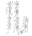
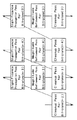
本実施の形態における画像符号化装置の概略構成を図1に示す。図1に示すように、画像符号化装置1は、DCレベルシフト部10と、ウェーブレット変換部11と、量子化部12と、符号ブロック化部13と、ビットプレーン分解部14と、符号化対象予測部15と、ビットモデリング部16と、算術符号化部17と、レート制御部19と、ヘッダ生成部20と、パケット生成部21とから構成されている。ここで、ビットモデリング部16と算術符号化部17とにより、EBCOT(Embedded Coding with Optimized Truncation)部18が構成される。
(1) Configuration and Operation of Image Encoding Device FIG. 1 shows a schematic configuration of the image encoding device in the present embodiment. As shown in FIG. 1, the
DCレベルシフト部10は、後段のウェーブレット変換部11におけるウェーブレット変換を効率的に行い圧縮率を向上させるために、原信号のレベルシフトを行う。原理的には、RGB信号は、正の値(符号なしの整数値)を持つため、原信号のダイナミックレンジを半分にするレベルシフトを行うことで、圧縮効率を向上させることができる。これに対して、YCbCr信号におけるCbやCrといった色差信号は、正負両方の整数値を持つため、レベルシフトは行われない。
The DC
ウェーブレット変換部11は、通常、低域フィルタと高域フィルタとから構成されるフィルタバンクによって実現される。なお、デジタルフィルタは、通常複数タップ長のインパルス応答(フィルタ係数)を持っているため、フィルタリングが行えるだけの入力画像を予めバッファリングしておく必要があるが、簡単のため、図1では図示を省略する。
The
DCレベルシフト部10は、フィルタリングに必要な最低限の画像信号D10を入力し、上述のようにレベルシフトを行う。そして、ウェーブレット変換部11は、DCレベルシフト後の画像信号D11に対して、ウェーブレット変換を行うフィルタリング処理を行い、ウェーブレット変換係数D12を生成する。
The DC
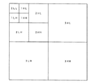
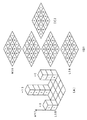
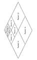
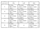
このウェーブレット変換では、通常図2に示すように低域成分が繰り返し変換されるが、これは画像のエネルギの多くが低域成分に集中しているためである。このことは、図3(A)に示す分割レベル=1から図3(B)に示す分割レベル=3のように、分割レベルを進めていくに従って、同図のようにサブバンドが形成されていくことからも分かる。ここで、図2におけるウェーブレット変換のレベル数は3であり、この結果計10個のサブバンドが形成されている。ここで、図2においてL,Hはそれぞれ低域,高域を表し、L,Hの前の数字は分割レベルを表す。すなわち、例えば1LHは、水平方向が低域で垂直方向が高域である分割レベル=1のサブバンドを表す。 In this wavelet transform, the low frequency components are usually repeatedly transformed as shown in FIG. 2, because most of the energy of the image is concentrated on the low frequency components. This is because subbands are formed as shown in the figure as the division level is advanced from division level = 1 shown in FIG. 3A to division level = 3 shown in FIG. 3B. It can be seen from going. Here, the number of wavelet transform levels in FIG. 2 is 3, and as a result, a total of 10 subbands are formed. Here, L and H in FIG. 2 represent a low frequency and a high frequency, respectively, and the numbers before L and H represent a division level. That is, for example, 1LH represents a subband of division level = 1 in which the horizontal direction is a low frequency and the vertical direction is a high frequency.
量子化部12は、ウェーブレット変換部11から供給されたウェーブレット変換係数D12に対して非可逆圧縮を施す。量子化手段としては、ウェーブレット変換係数D12を量子化ステップサイズで除算するスカラ量子化を用いることができる。ここで、JPEG−2000方式の規格上、上述の非可逆圧縮を行う場合で、非可逆の9×7ウェーブレット変換フィルタを用いる場合には、自動的にスカラ量子化を併用することが決められている。一方、可逆の5×3ウェーブレット変換フィルタを用いる場合には、量子化が行われず、後述するレート制御部19において符号量制御が行われる。したがって、図1の量子化部12が動作するのは、実際には非可逆の9×7ウェーブレット変換フィルタを用いた場合である。以下、この非可逆の9×7ウェーブレット変換フィルタを用いる場合を想定して説明を進める。
The
符号ブロック化部13は、量子化部12で生成された量子化係数D13を、エントロピー符号化の処理単位である所定の大きさの符号ブロックに分割する。ここで、サブバンド中の符号ブロックの位置関係を図4に示す。通常、例えば64×64程度のサイズの符号ブロックが、分割後の全てのサブバンド中に生成される。したがって、図2において最も分割レベルが小さい3HHのサブバンドの大きさが640×320であった場合には、64×64の符号ブロックは、水平方向に10個、垂直方向に5個、合計50個存在することになる。符号ブロック化部13は、符号ブロック毎の量子化係数D14をビットプレーン分解部14に供給し、後段の符号化処理は、これらの符号ブロック毎に行われる。
The
ビットプレーン分解部14は、符号ブロック毎の量子化係数D14をビットプレーンに分解する。このビットプレーンの概念について図5を用いて説明する。図5(A)は、縦4個、横4個の計16個の係数からなる量子化係数を仮定したものである。この16個の係数のうち絶対値が最大のものは13であり、2進数表現では1101となる。したがって、係数の絶対値のビットプレーンは、図5(B)に示すような4つのビットプレーンから構成される。なお、各ビットプレーンの要素は、全て0又は1の数をとる。一方、量子化係数の符号は、−6が唯一負の値であり、それ以外は0又は正の値である。したがって、符号のビットプレーンは、図5(C)に示すようになる。ビットプレーン分解部14は、このビットブレーンに分解された量子化係数D15を符号化対象予測部15に供給する。
The bit
符号化対象予測部15は、ビットプレーン分解部14においてビットブレーンに分解された量子化係数D15に基づいて、最終的に符号化されるビットプレーン数又は符号化パス数をEBCOT部18で符号化する前に事前予測し、予測されたビットプレーンを抽出して、抽出したビットプレーン毎の係数ビットD16をビットモデリング部16に供給する。なお、この符号化対象予測部15における予測処理の詳細については後述する。
The encoding
ビットモデリング部16は、符号化対象予測部15から供給されたビットプレーン毎の係数ビットD16に対して、以下のようにして係数ビットモデリングを行い、係数ビット毎のコンテキストD17を算術符号化部17に供給する。そして、算術符号化部17は、この係数ビット毎のコンテキストD17に対して算術符号化を施し、得られた算術符号D18をレート制御部19に供給する。ここで、本実施の形態では、特にJPEG−2000規格で定められたEBCOTと呼ばれるエントロピー符号化を例に取りながら説明する。このEBCOTについては、例えば、文献「IS0/IEC 15444-1, Information technology-JPEG 2000, Part 1:Core coding system」等に詳細に記載されている。なお、上述したように、ビットモデリング部16と算術符号化部17とにより、EBCOT部18が構成される。
The
EBCOTは、所定の大きさのブロック毎にそのブロック内の係数ビットの統計量を測定しながら符号化する手段であり、符号ブロック単位に量子化係数をエントロピー符号化する。符号ブロックは、最上位ビット(MSB)から最下位ビット(LSB)方向にビットプレーン毎に独立して符号化される。また、符号ブロックの縦横のサイズは、4から256までの2の冪乗で、通常は32×32、64×64、128×32等の大きさが使用される。量子化係数は、nビットの符号付き2進数で表されており、bit0からbit(n−2)がLSBからMSBまでのそれぞれのビットを表す。なお、残りの1ビットは符号である。符号ブロックの符号化は、MSB側のビットプレーンから順番に、以下の(a)〜(c)に示す3種類の符号化パスによって行われる。
(a) Significance Propagation Pass
(b) Magnitude Refinement Pass
(c) Clean Up Pass
EBCOT is a means for encoding for each block of a predetermined size while measuring the statistical amount of coefficient bits in the block, and entropy-encodes the quantized coefficient in units of code blocks. The code block is encoded independently for each bit plane in the direction from the most significant bit (MSB) to the least significant bit (LSB). The vertical and horizontal sizes of the code block are powers of 2 from 4 to 256, and sizes such as 32 × 32, 64 × 64, and 128 × 32 are usually used. The quantization coefficient is represented by an n-bit signed binary number, and bit0 to bit (n−2) represent respective bits from LSB to MSB. The remaining 1 bit is a code. The coding of the code block is performed by the three kinds of coding passes shown in the following (a) to (c) in order from the bit plane on the MSB side.
(a) Significance Propagation Pass
(b) Magnitude Refinement Pass
(c) Clean Up Pass
3つの符号化パスの用いられる順序を図6に示す。図6に示すように、先ずビットプレーン(n−2)(MSB)がClean Up Pass(以下、適宜CUパスという。)によって符号化される。続いて、順次LSB側に向かい、各ビットプレーンが、Significance Propagation Pass(以下、適宜SPパスという。)、Magnitude Refinement Pass(以下、適宜MRパスという。)、Clean Up Pass の順序で用いられて符号化される。 The order in which the three coding passes are used is shown in FIG. As shown in FIG. 6, first, the bit plane (n-2) (MSB) is encoded by a Clean Up Pass (hereinafter referred to as a CU pass as appropriate). Subsequently, each bit plane is sequentially used in the order of Significance Propagation Pass (hereinafter referred to as SP pass), Magnitude Refinement Pass (hereinafter referred to as MR pass), and Clean Up Pass. It becomes.
但し、実際にはMSB側から何番目のビットプレーンで初めて1が出てくるかをヘッダに書き、ゼロ係数から構成されるビットプレーン(ゼロビットプレーン)は符号化しない。この順序で3種類の符号化パスを繰返し用いて符号化し、任意のビットプレーンの任意の符号化パスまでで符号化を打ち切ることにより、符号量と画質のトレードオフを取る、すなわちレート制御を行うことができる。 In practice, however, the first bit plane from the MSB side where 1 appears for the first time is written in the header, and the bit plane composed of zero coefficients (zero bit plane) is not encoded. In this order, encoding is performed by repeatedly using three types of encoding passes, and the encoding is terminated up to an arbitrary encoding pass of an arbitrary bit plane, thereby taking a trade-off between code amount and image quality, that is, rate control is performed. be able to.
ここで、係数ビットの走査(スキャニング)について図7を用いて説明する。符号ブロックは、高さ4個の係数ビット毎にストライプ(stripe)に分けられる。ストライプの幅は、符号ブロックの幅に等しい。スキャン順とは1個の符号ブロック内の全ての係数ビットを辿る順番であり、符号ブロック中では上のストライプから下のストライプへの順序、各ストライプ中では左の列から右の列への順序、各列中では上から下への順序でスキャニングされる。なお、各符号化パスにおいて符号ブロック中の全ての係数ビットがこのスキャン順で処理される。 Here, scanning (scanning) of coefficient bits will be described with reference to FIG. The code block is divided into stripes every four coefficient bits in height. The width of the stripe is equal to the width of the code block. The scan order is the order in which all the coefficient bits in one code block are traced. In the code block, the order is from the upper stripe to the lower stripe, and in each stripe, the order is from the left column to the right column. In each row, scanning is performed from top to bottom. In each coding pass, all coefficient bits in the code block are processed in this scan order.
以下、上述した3つの符号化パスについて説明する。なお、この3つの符号化パスについては、何れも上述した文献「IS0/IEC 15444-1, Information technology-JPEG 2000, Part 1:Core coding system」に記載されている。 Hereinafter, the three coding passes described above will be described. Note that these three coding passes are all described in the above-mentioned document “IS0 / IEC 15444-1, Information technology-JPEG 2000, Part 1: Core coding system”.
(a) Significance Propagation Pass
あるビットプレーンを符号化するSPパスでは、8近傍の少なくとも1つの係数が有意(significant)であるようなnon-significantな係数ビットが算術符号化される。その符号化した係数ビットの値が1である場合には、符号の正負が続けて算術符号化される。
(a) Significance Propagation Pass
In the SP pass for encoding a bit plane, non-significant coefficient bits in which at least one coefficient in the vicinity of 8 is significant are arithmetically encoded. When the value of the encoded coefficient bit is 1, the sign of the sign is continued and arithmetic coding is performed.
ここでsignificanceとは、各係数ビットに対して符号化器が持つ状態である。significanceの初期値は、non-significantを表す「0」であり、その係数で1が符号化されたときにsignificantを表す「1」に変化し、以降常に「1」であり続ける。したがって、significanceとは、有効桁の情報を既に符号化したか否かを示すフラグともいえる。あるビットプレーンでSPパスが発生すれば、以降のビットプレーンではSPパスは発生しない。 Here, the significance is a state that the encoder has for each coefficient bit. The initial value of significance is “0” representing non-significant, changes to “1” representing significant when 1 is encoded with the coefficient, and continues to be always “1” thereafter. Therefore, the significance can also be said to be a flag indicating whether or not valid digit information has already been encoded. If an SP path is generated in a certain bit plane, no SP path is generated in the subsequent bit planes.
(b) Magnitude Refinement Pass
ビットプレーンを符号化するMRパスでは、ビットプレーンを符号化するSPパスで符号化していないsignificantな係数ビットが算術符号化される。
(b) Magnitude Refinement Pass
In the MR pass that encodes the bit plane, significant coefficient bits that are not encoded in the SP pass that encodes the bit plane are arithmetically encoded.
(c) Clean Up Pass
ビットプレーンを符号化するCUパスでは、ビットプレーンを符号化するSPパスで符号化していないnon-significantな係数ビットが算術符号化される。その符号化した係数ビットの値が1である場合には、符号の正負が続けて算術符号化される。
(c) Clean Up Pass
In the CU pass that encodes the bit plane, non-significant coefficient bits that are not encoded in the SP pass that encodes the bit plane are arithmetically encoded. When the value of the encoded coefficient bit is 1, the sign of the sign is continued and arithmetic coding is performed.
なお、以上の3つの符号化パスでの算術符号化では、ケースに応じてZC(Zero Coding)、RLC(Run-Length Coding)、SC(Sign Coding)、MR(Magnitude Refinement)が使い分けられて係数のコンテキストが選択される。そして、MQ符号化と呼ばれる算術符号によって選択されたコンテキストが符号化される。このMQ符号化は、JBIG2で規定された学習型の2値算術符号である。MQ符号化については、例えば、文献「ISO/IEC FDIS 14492, “Lossy/Lossless Coding of Bi-level Images”, March 2000」等に記載されている。JPEG−2000では、全ての符号化パスで合計19種類のコンテキストがある。 In arithmetic coding in the above three coding passes, ZC (Zero Coding), RLC (Run-Length Coding), SC (Sign Coding), and MR (Magnitude Refinement) are used properly according to the case. Context is selected. Then, the selected context is encoded by an arithmetic code called MQ encoding. This MQ coding is a learning type binary arithmetic code defined by JBIG2. The MQ coding is described in, for example, the document “ISO / IEC FDIS 14492,“ Lossy / Lossless Coding of Bi-level Images ”, March 2000”. In JPEG-2000, there are a total of 19 contexts in all coding passes.
以上のようにして、ビットモデリング部16は、ビットプレーン毎の係数ビットD16を3つの符号化パスで処理し、係数ビット毎のコンテキストD17を生成する。そして、算術符号化部17は、この係数ビット毎のコンテキストD17に対して算術符号化を施す。
As described above, the
レート制御部19は、少なくとも一部の符号化パスの処理を行った後で、算術符号化部17から供給された算術符号D18の符号量をカウントし、目標の符号量に達した時点で、それより後の算術符号D18を切り捨てる。このように、符号量をオーバーする直前で切り捨てることにより、確実に目標の符号量に抑えることができる。レート制御部19は、この符号量制御完了後の算術符号D19を、ヘッダ生成部20及びパケット生成部21に供給する。なお、レート制御部19におけるレート制御処理の詳細については後述する。
The
ヘッダ生成部20は、レート制御部19から供給された符号量制御完了後の算術符号D19に基づいて、符号ブロック内での付加情報、例えば符号ブロック内の符号化パスの個数や圧縮コードストリームのデータ長等をヘッダD20として生成し、このヘッダD20をパケット生成部21に供給する。
Based on the arithmetic code D19 after completion of the code amount control supplied from the
パケット生成部21は、符号量制御完了後の算術符号D19とヘッダD20とを合わせてパケットD21を生成し、符号化コードストリームとして出力する。この際、パケット生成部21は、図8に示すように同一解像度レベルから個々のパケットを生成する。なお、図8から分かるように、最低域であるパケット−1は、LL成分のみを含み、それ以外のパケット−2乃至パケット−4は、LH成分,HL成分及びHH成分を含む。
The
以上のように、本実施の形態における画像符号化装置1は、ウェーブレット変換及びエントロピー符号化を用いて入力画像を高効率に圧縮符号化し、パケット化して符号化コードストリームとして出力することができる。
As described above, the
(2)画像符号化装置における適用部分
(2−1)符号化対象予測部の構成及び動作
ところで、一般にJPEG−2000方式により入力画像を圧縮符号化する画像符号化装置では、EBCOTにおけるエントロピー符号化の処理負荷が非常に高い。その一方で、目標の圧縮率又はビットレートで符号化する際には、EBCOTで符号化した後に実際には使用されないものが存在し、これらは結果的に無駄になる。
(2) Application Part in Image Encoding Device (2-1) Configuration and Operation of Encoding Target Prediction Unit By the way, in an image encoding device that generally compresses and encodes an input image by the JPEG-2000 method, entropy encoding in EBCOT The processing load is very high. On the other hand, when encoding at a target compression rate or bit rate, there are some that are not actually used after encoding with EBCOT, and as a result, they are wasted.
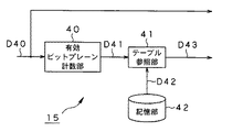
そこで、本実施の形態における符号化対象予測部15は、最終的に使用される蓋然性の高いビットプレーンを事前予測し、このビットプレーンのみを抽出して上述したEBCOT部18に供給する。具体的には、1フレーム分又は1サブバンド分の有効ビットプレーン数を計数し、この有効ビットプレーン数を発生する符号量についての指標として用いて、最終的に符号化されるビットプレーン数を予測する。
Therefore, the encoding
この符号化対象予測部15の内部構成の一例を図9に示す。図9に示すように、符号化対象予測部15は、上述した有効ビットプレーン数を計数する有効ビットプレーン計数部30と、ビットプレーン数テーブルを参照して、この有効ビットプレーン数から符号化対象となるビットプレーン数を予測するテーブル参照部31と、ビットプレーン数テーブルを記憶する記憶部32と、符号化対象となるビットプレーン数に基づいて、後述するように符号化対象ビットプレーンを抽出する符号化対象ビットプレーン抽出部33とから構成されている。なお、この記憶部32としては、読み取り専用の不揮発性記憶媒体であるROM(Read Only Memory)を用いることができる。
An example of the internal configuration of the encoding
有効ビットプレーン計数部30は、符号ブロック毎のビットプレーンD30を入力し、ゼロ係数から構成されるビットプレーン(ゼロビットプレーン)を除く有効ビットプレーン数を計数する。さらに、有効ビットプレーン計数部30は、フレーム内又はサブバンド内の全ての符号ブロックの有効ビットプレーン数を加算し、算出された有効ビットプレーン数の総和D31をテーブル参照部31に供給する。
The valid bit
テーブル参照部31は、記憶部32に記憶されているビットプレーン数テーブルを参照して、有効ビットプレーン計数部30から供給された有効ビットプレーン数の総和D31から符号化対象ビットプレーン数D32を読み出し、読み出した符号化対象ビットプレーン数D33を符号化対象ビットプレーン抽出部33に供給する。
The
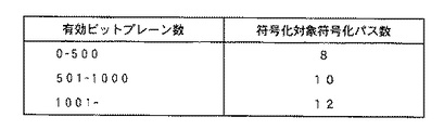
ここで、ビットプレーン数テーブルは、有効ビットプレーン数の値域とその値域における符号化対象ビットプレーン数とが対応付けられたものである。 Here, the bit plane number table is a table in which the range of the number of effective bit planes is associated with the number of bit planes to be encoded in the range.
例えば、フレーム毎の有効ビットプレーン数の総和を用いる場合には、図10に示すように、有効ビットプレーン数の値域に対して符号化対象ビットプレーン数が対応したものとなる。この場合、1フレーム内の符号化ブロックにおける有効ビットプレーン数の総和が「600」であれば、このビットプレーン数テーブルを参照することで、即座に符号化対象ビットプレーン数として「5」という数字が得られる。 For example, when the total number of effective bit planes for each frame is used, as shown in FIG. 10, the number of encoding target bit planes corresponds to the range of the effective bit plane number. In this case, if the sum of the number of effective bit planes in the coding block in one frame is “600”, the number “5” is immediately set as the number of bit planes to be encoded by referring to this bit plane number table. Is obtained.
一方、サブバンド毎の有効ビットプレーン数の総和を用いる場合には、図11に示すように、各サブバンド内の有効ビットプレーン数の値域に対して符号化対象ビットプレーン数が対応したものとなる。ここで、図11は、図12に示すように5回ウェーブレット変換・分割を行う場合のテーブル例を示したものである。この場合、分割レベル=3でLHのサブバンド内の有効ビットプレーン数の総和が「100」であれば、このビットプレーン数テーブルを参照することで、即座に符号化対象ビットプレーン数として「3」という数字が得られる。他のサブバンドについても同様である。なお、図10のビットプレーン数テーブルよりも図11のビットプレーン数テーブルの方が、きめ細かい制御が可能であり、より高精度に有効ビットプレーン数を予測することができる。 On the other hand, when the sum of the number of effective bit planes for each subband is used, the number of encoding target bitplanes corresponds to the range of the number of effective bitplanes in each subband, as shown in FIG. Become. Here, FIG. 11 shows an example of a table when the wavelet transform / division is performed five times as shown in FIG. In this case, if the sum of the number of effective bit planes in the LH subband is “100” at the division level = 3, the number of bit planes to be encoded is “3” immediately by referring to this bit plane number table. "Is obtained. The same applies to the other subbands. Note that the bit plane number table in FIG. 11 can perform finer control than the bit plane number table in FIG. 10, and the number of effective bit planes can be predicted with higher accuracy.
図9に戻って、符号化対象ビットプレーン抽出部33は、テーブル参照部31から供給された符号化対象ビットプレーン数D33に基づいて、符号ブロック毎のビットプレーンD30から符号化対象ビットプレーンD34のみを抽出する。具体的には、各符号ブロック毎に、最上位ビット(MSB)側から符号化対象ビットプレーン数分のビットプレーンを抽出する。そして符号化対象ビットプレーン抽出部33は、抽出した符号化対象ビットプレーンD34を、図1に示したビットモデリング部16に供給する。
Returning to FIG. 9, the encoding target bit
この抽出された符号化対象ビットプレーンD34のみが後段のEBCOT部18で実際に符号化されるため、抽出された符号化対象ビットプレーンD34の数が元の符号ブロック毎のビットプレーンD30の数よりも少なければ、その分だけ処理負荷を軽減し、符号化に費やす時間を短縮することができる。
Since only the extracted encoding target bit plane D34 is actually encoded by the
また、本実施の形態における符号化対象予測部15は、予め有効ビットプレーン数と符号化対象ビットプレーン数とを対応付けたビットプレーン数テーブルを参照するのみであるため、このテーブルを記憶するだけのメモリ容量で済み、極めて処理負荷が小さい。
In addition, since the encoding
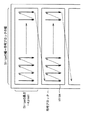
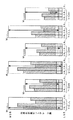
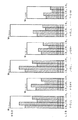
以上の処理を、図13を用いて、ビットプレーンの観点から具体的に説明する。この図13は、Y(輝度)、U,V(色差)の3つのコンポーネントに対して各サブバンド内の符号ブロック(CB)毎のビットプレーンを図示したものである。例えば、右端のV−5HHは、色差成分Vの5HH、すなわち水平方向及び垂直方向が高域である分割レベル=5のサブバンド中に存在する符号ブロック(CB)毎のビットプレーンを示す。また、図13において、空白領域はゼロビットプレーンを示し、斜線領域は符号化コードストリームに最終的に含まれるビットプレーンを示し、点領域は後段におけるレート制御の結果、使用されないビットプレーンを示す。なお、斜線領域と点領域とを合わせたビットプレーン数が、有効ビットプレーン数に相当する。 The above processing will be specifically described from the viewpoint of the bit plane with reference to FIG. FIG. 13 illustrates a bit plane for each code block (CB) in each subband for three components of Y (luminance), U, and V (color difference). For example, V-5HH at the right end indicates a bit plane for each code block (CB) existing in 5HH of the color difference component V, that is, in a subband of division level = 5 in which the horizontal direction and the vertical direction are high frequencies. In FIG. 13, a blank area indicates a zero bit plane, a hatched area indicates a bit plane that is finally included in the encoded code stream, and a dot area indicates a bit plane that is not used as a result of rate control in the subsequent stage. Note that the number of bit planes combining the shaded area and the dot area corresponds to the number of effective bit planes.
符号化対象予測部15においては、上述したように、フレーム毎又はサブバンド毎の全符号ブロックにおける有効ビットプレーン数の総和から、符号化対象ビットプレーン数が求められる。そして、各符号ブロック(CB)毎に、最上位ビット(MSB)側から符号化対象ビットプレーン数分のビットプレーンが抽出される。
As described above, the encoding
点領域中にある境界線は、符号化対象予測部15において抽出されるビットプレーンと抽出されないビットプレーンとの境界を示している。すなわち、この境界線よりも最下位ビット(LSB)側に存在しているビットプレーンは、符号化対象予測部15において抽出されない。
A boundary line in the point area indicates a boundary between a bit plane extracted by the encoding
図14は、図13のY−0LL、すなわち輝度成分Yの最低域のサブバンドに着目した図である。図14中で黒く塗った領域は、結果的にEBCOT部18での符号化を省略することのできるビットプレーンである。
FIG. 14 is a diagram paying attention to Y-0LL of FIG. 13, that is, the lowest band of the luminance component Y. In FIG. 14, the black area is a bit plane that can be omitted in the
なお、この例では、各コンポーネント毎に同一のサブバンド内の全ての符号ブロックについて符号化対象ビットプレーン数を一定としたが、これに限定されるものではなく、コンポーネント毎、或いは符号ブロック毎に符号化対象ビットプレーン数を可変に設定することもできる。但し、この場合には、コンポーネント毎、或いは符号ブロック毎に符号化対象ビットプレーン数が設定されたビットプレーン数テーブルが必要となる。 In this example, the number of bit planes to be encoded is constant for all the code blocks in the same subband for each component, but the present invention is not limited to this, and for each component or code block It is also possible to variably set the number of encoding target bit planes. However, in this case, a bit plane number table in which the number of encoding target bit planes is set for each component or code block is required.
また、上述の説明では、ビットプレーン数テーブルを参照して、有効ビットプレーン数から符号化対象ビットプレーン数を予測するものとしたが、有効ビットプレーン数から符号化対象符号化パス数を予測するようにしても構わない。 In the above description, the number of encoding target bitplanes is predicted from the number of effective bitplanes by referring to the bitplane number table, but the number of encoding target encoding passes is predicted from the number of effective bitplanes. It doesn't matter if you do.
この場合における符号化対象予測部15の内部構成を図15に示す。図15に示すように、符号化対象予測部15は、上述した有効ビットプレーン数を計数する有効ビットプレーン計数部40と、ビットプレーン数テーブルを参照して、この有効ビットプレーン数から符号化対象となる符号化パス数を求めるテーブル参照部41と、符号化パス数テーブルを記憶する記憶部42とから構成されている。
FIG. 15 shows an internal configuration of the encoding
有効ビットプレーン計数部40は、符号ブロック毎のビットプレーンD40を入力して有効ビットプレーン数を計数し、フレーム内又はサブバンド内の全ての符号ブロックの有効ビットプレーン数を加算した有効ビットプレーン数の総和D41をテーブル参照部41に供給する。
The effective bit
テーブル参照部41は、記憶部42に記憶されている符号化パス数テーブルを参照して、有効ビットプレーン計数部40から供給された有効ビットプレーン数の総和D41から符号化対象符号化パス数D42を読み出し、読み出した符号化対象符号化パス数D43を図1に示したビットモデリング部16に供給する。
The
ここで、符号化パス数テーブルは、有効ビットプレーン数の値域とその値域における符号化対象符号化パス数とが対応付けられたものである。 Here, the encoding pass number table associates the range of the number of effective bit planes with the number of encoding target encoding passes in the range.
例えば、フレーム毎の有効ビットプレーン数の総和を用いる場合には、図16に示すように、有効ビットプレーン数の値域に対して符号化対象符号化パス数が対応したものとなる。なお、図10と比較して分かる通り、1ビットプレーンでは最大で3個の符号化パスが発生する場合があるため、それを考慮して図10の符号化対象ビットプレーン数よりも大きな数字に設定されている。 For example, when the total number of effective bit planes for each frame is used, the number of encoding target encoding passes corresponds to the range of the number of effective bit planes as shown in FIG. As can be seen from the comparison with FIG. 10, since a maximum of three coding passes may occur in one bit plane, the number is larger than the number of bit planes to be coded in FIG. It is set.
後段のEBCOT部18では、各符号ブロック毎に、最上位ビット(MSB)側のビットプレーンから符号化対象符号化パス数分の符号化パスのみが実際に符号化されるため、符号化対象符号化パス数D43が元の符号ブロック毎のビットプレーンD40に発生する符号化パスの数よりも少なければ、その分だけ処理負荷を軽減し、符号化に費やす時間を短縮することができる。
Since the
(2−2)レート制御部の構成及び動作
図1において算術符号化部17から供給された算術符号D18は、レート制御部19を経由しないでそのまま後段部に行くと、目標の圧縮率又はビットレートでない符号化コードストリームが排出される蓋然性が高い。したがって、レート制御部19で最終的なレート制御が行われる必要がある。
(2-2) Configuration and Operation of Rate Control Unit When the arithmetic code D18 supplied from the
ここで、本実施の形態におけるレート制御部19は、優先順位の高い算術符号から順に選択してその符号量を加算し、目標の符号量に達した時点で停止する。
Here, the
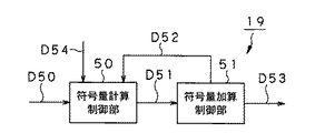
このレート制御部19の内部構成の一例を図17に示す。図17に示すように、レート制御部19は、符号量計算制御部50と、符号量加算制御部51とにより構成されている。
An example of the internal configuration of the
符号量計算制御部50は、算術符号化部17(図1)から供給された算術符号D50のビットプレーン毎の符号量D51を計算し、符号量加算制御部51に供給する。符号量加算制御部51は、後述する優先順位に従って、1ビットプレーンずつ符号量D51を加算する。加算されたビットプレーン情報D52は、再び符号量計算制御部50に供給され、それまでに加算された全てのビットプレーンの符号量と目標符号量D54とが比較される。そして、目標符号量D54に達した時点でこのループ制御を終了し、最終的な符号量制御後の算術符号D53を、図1に示したヘッダ生成部20及びパケット生成部21に供給する。
The code amount
ここで、ビットプレーン毎の符号量D51を加算する優先順位は、以下の通りである。すなわち、全サブバンドの最上位ビット(MSB)のビットプレーンのうち、サブバンド間で最もビット位置が高いものから最下位ビット(LSB)のビットプレーンの順に選択する。 Here, the priority order of adding the code amount D51 for each bit plane is as follows. That is, among the most significant bit (MSB) bit planes of all the subbands, the bit plane having the highest bit position between the subbands is selected in order from the least significant bit (LSB) bit plane.
また、各サブバンドの同じビット位置のビットプレーンについては、最低域のサブバンドから最高域のサブバンドの順に選択する。例えば図2に示したように3回ウェーブレット変換・分割を行った場合、図18に示すように、0LL、1HL、1LH、1HH、2HL、2LH、2HH、3HL、3LH、3HHの順に選択する。これは、画像の重要な部分が高域よりも低域に集まっているためである。 In addition, bit planes at the same bit position in each subband are selected in the order of the lowest subband to the highest subband. For example, when wavelet transform / division is performed three times as shown in FIG. 2, selection is made in the order of 0LL, 1HL, 1LH, 1HH, 2HL, 2LH, 2HH, 3HL, 3LH, and 3HH as shown in FIG. This is because important parts of the image are gathered in the low range rather than the high range.
また、Y(輝度)、U,V(色差)の3つのコンポーネントの同じビット位置のビットプレーンについては、例えば、Y、U、Vの順に選択する。これは、一般に色差情報よりも輝度情報に対して人間の視覚特性が敏感なためである。なお、同じ色差情報であるU及びVの重要度は入力画像に依存するため、優先順位を適宜可変にすることが好ましい。 Further, bit planes at the same bit positions of the three components Y (luminance), U, and V (color difference) are selected in the order of Y, U, and V, for example. This is because human visual characteristics are generally more sensitive to luminance information than color difference information. Since the importance of U and V, which are the same color difference information, depends on the input image, it is preferable to change the priority appropriately.
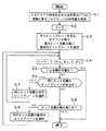
このビットプレーンの加算処理手順を図19のフローチャートに示す。先ずステップS1において、EBCOT部18で符号化された全符号化パスの情報と各ビットプレーンの符号量とを保持する。
This bit plane addition processing procedure is shown in the flowchart of FIG. First, in step S1, information on all coding passes encoded by the
次にステップS2において、加算符号量Yを0に初期化し、続くステップS3において、ゼロビットプレーンを含む、サブバンド間で最もビット位置の高い最初のビットプレーンを選択する。ここで、同じビット位置に複数のビットプレーンが存在する場合には、上述の通り、サブバンドについては最低域のサブバンドから最高域のサブバンドの順に、コンポーネントについては例えばY、U、Vの順に選択する。 Next, in step S2, the added code amount Y is initialized to 0, and in the subsequent step S3, the first bit plane having the highest bit position between subbands including the zero bit plane is selected. Here, when there are a plurality of bit planes at the same bit position, as described above, for the subbands, for example, Y, U, and V for components in the order of the lowest band to the highest band. Select in order.
続いてステップS4において、選択したビットプレーンの符号量T[Ns,Nc,C,B]をYに加算する。ここで、Ns,Nc,C,Bは、それぞれサブバンド番号、コンポーネント番号、符号ブロック番号、ビットプレーン番号を示す。 In step S4, the code amount T [Ns, Nc, C, B] of the selected bit plane is added to Y. Here, Ns, Nc, C, and B indicate a subband number, a component number, a code block number, and a bit plane number, respectively.
ステップS5では、加算符号量Yが目標符号量以上であるか否かが判別される。加算符号量Yが目標符号量以上である場合(Yes)には加算処理を終了し、符号量Yが目標符号量未満である場合(No)にはステップS6に進む。 In step S5, it is determined whether or not the added code amount Y is greater than or equal to the target code amount. When the added code amount Y is equal to or greater than the target code amount (Yes), the addition process is terminated, and when the code amount Y is less than the target code amount (No), the process proceeds to step S6.
ステップS6では、同じビット位置のビットプレーンが存在するか否かが判別される。同じビット位置のビットプレーンが存在する場合(Yes)にはステップS7に進み、次のビットプレーンを選択してステップS4に戻る。一方、同じビット位置のビットプレーンが存在しない場合(No)にはステップS8に進む。 In step S6, it is determined whether there is a bit plane at the same bit position. If there is a bit plane at the same bit position (Yes), the process proceeds to step S7, the next bit plane is selected, and the process returns to step S4. On the other hand, if there is no bit plane at the same bit position (No), the process proceeds to step S8.
ステップS8では、ビット位置が最も低いか否か、すなわち最下位ビット(LSB)か否かが判別される。ビット位置が最も低い場合(Yes)には加算処理を終了し、そうでない場合(No)にはステップS9において最下位ビット(LSB)側の次のビット位置の最初のビットプレーンを選択してステップS4に戻る。 In step S8, it is determined whether or not the bit position is the lowest, that is, the least significant bit (LSB). If the bit position is the lowest (Yes), the addition process is terminated. If not (No), the first bit plane of the next bit position on the least significant bit (LSB) side is selected in Step S9 and the step is performed. Return to S4.
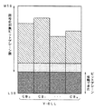
以上の処理を、図20を用いて、ビットプレーンの観点から具体的に説明する。この図20は、Y(輝度)、U,V(色差)の3つのコンポーネントに対して各サブバンド内の符号化ブロック(CB)毎のビットプレーンを図示している。図13と同様に、空白領域はゼロビットプレーンを示し、斜線領域は符号化コードストリームに最終的に含まれるビットプレーンを示し、点領域はレート制御の結果、使用されないビットプレーンを示す。 The above processing will be specifically described from the viewpoint of the bit plane with reference to FIG. FIG. 20 illustrates a bit plane for each coding block (CB) in each subband for three components of Y (luminance), U, and V (color difference). As in FIG. 13, the blank area indicates a zero bit plane, the hatched area indicates a bit plane that is finally included in the encoded code stream, and the dot area indicates a bit plane that is not used as a result of rate control.
図20に示すように、レート制御部19においては、ゼロビットプレーンを含む最もビット位置の高いビットプレーンから最もビット位置の低いビットプレーン、すなわち最下位ビット(LSB)のビットプレーンの順に、サブバンド、コンポーネントを渡りながら選択され、同じビット位置ではサブバンドについては最低域のサブバンドから最高域のサブバンドの順に、コンポーネントについては例えばY、U、Vの順にビットプレーンが選択される。具体的には、図20において、Y−0LL、U−0LL及びV−0LLのビット位置がサブバンド間で最も高いため、Y−0LL、U−0LL、V−0LLの順に最上位ビット(MSB)側からビットプレーンが選択される。
As shown in FIG. 20, in the
なお、この例では、Y−0LL〜Y−5HH、U−0LL〜U−5HH、V−0LL〜V−5HHと、サブバンド毎の選択をコンポーネント毎の選択に優先させているが、これに限定されるものではなく、コンポーネント毎の選択をサブバンド毎の選択に優先させるようにしても構わない。 In this example, Y-0LL to Y-5HH, U-0LL to U-5HH, V-0LL to V-5HH, and the selection for each subband are given priority over the selection for each component. The selection is not limited, and selection for each component may be given priority over selection for each subband.
このように、本実施の形態におけるレート制御部19によれば、最終的に選択されずに切り捨てられるビットプレーン数が、1フレーム内の全ての符号ブロックに対して最下位ビット(LSB)側から数えて最大でも1ビットプレーンしか相違しないため、サブバンド間の画質差がなくなり、全体的に高画質な画像が得られる。
As described above, according to the
(2−3)量子化部の動作
上述したように、量子化部12は、ウェーブレット変換部11から供給されたウェーブレット変換係数D12に対して、量子化ステップサイズで除算するスカラ量子化により非可逆圧縮を施す。
(2-3) Operation of Quantization Unit As described above, the
ところで、JPEG−2000規格で規定されている量子化は、以下の式(1)に示すように、ある変換係数ab(x,y)(但し、xは水平方向の位置を示し、yは垂直方向の位置を示す)を、サブバンドbの量子化ステップサイズΔWbで除算することによって、量子化係数Qb(x,y)を算出するものである。 By the way, the quantization defined in the JPEG-2000 standard is a conversion coefficient a b (x, y) (where x indicates the position in the horizontal direction and y is The quantization coefficient Q b (x, y) is calculated by dividing (vertical position) by the quantization step size ΔW b of the subband b.

式(1)におけるΔWbは、以下の式(2)に従って算出することができる。ここで、ΔB−Stepは、全サブバンドで共通の基本ステップサイズを示し、L2bは、サブバンドbの合成フィルタ基底波形のL2ノルムを示し、ΔNbは、サブバンドbの正規化量子化ステップサイズを示す。 ΔW b in equation (1) can be calculated according to equation (2) below. Here, ΔB-Step indicates a basic step size common to all subbands, L2 b indicates the L2 norm of the combined filter base waveform of subband b , and ΔN b indicates normalized quantization of subband b. Indicates the step size.
次に、ΔWbが算出されてから、以下の式(3)に従って指数εb及び仮数μbを求める。ここで、Rbはサブバンドbにおけるダイナミックレンジである。これらの値εb、μbが実際に最終的な符号化コードストリームに含まれることになる。 Next, after ΔW b is calculated, an index ε b and a mantissa μ b are obtained according to the following equation (3). Here, R b is the dynamic range in subband b. These values ε b and μ b are actually included in the final encoded code stream.
ここで、本実施の形態における量子化部12は、量子化ステップサイズΔWbを求める際に、上述した式(2)を用いるのではなく、サブバンドb毎の重み係数VWbを用いて、以下の式(4)に従って算出する。
Here, the
この重み係数VWbは、サブバンド毎、或いはY(輝度)、Cb,Cr(色差)といったコンポーネント毎に設定することができ、重み係数テーブルとして記憶される。この重み係数の値が大きい場合には、上述した式(3)からΔWbが小さくなり、式(1)から量子化係数Qb(x,y)が大きくなるため、画像の重要な部分が集中している低域ほど値を大きくすることが好ましい。また、色差情報(Cb,Cr)よりも輝度情報(Y)に対して人間の視覚特性が敏感であるため、輝度情報(Y)の方の値を大きくすることが好ましい。 The weighting factor VW b are each subband, or Y (luminance), Cb, can be set for each component such as Cr (color difference) is stored as the weighting coefficient table. When the value of the weighting factor is large, ΔW b is reduced from the above-described equation (3), and the quantization coefficient Q b (x, y) is increased from the equation (1). It is preferable to increase the value as the low frequencies are concentrated. Further, since the human visual characteristic is more sensitive to the luminance information (Y) than the color difference information (Cb, Cr), it is preferable to increase the value of the luminance information (Y).
図12のように5回ウェーブレット変換・分割を行う場合の重み係数テーブルの一例を図21に示す。図21に示すように、分割レベルが小さい低域ほど値が大きく、また、色差情報(Cb,Cr)よりも輝度情報(Y)の方が値が大きくなっている。 FIG. 21 shows an example of a weighting coefficient table in the case where the wavelet transformation / division is performed five times as shown in FIG. As shown in FIG. 21, the value is larger as the division level is lower, and the luminance information (Y) is larger than the color difference information (Cb, Cr).
後段の符号ブロック化部13では、量子化部12で生成された量子化係数D13が所定の大きさの符号ブロックに分割され、ビットプレーン分解部14では、符号ブロック毎の量子化係数D14がビットプレーンに分解されるため、量子化係数の値が大きいほど、ビットプレーン数が多くなる。したがって、上述したように、レート制御部19において、全ての符号ブロックで最もビット位置の高い算術符号から最下位ビットの算術符号の順に、ビットプレーン毎又は符号化パス毎の算術符号を選択する場合には、より重要な情報を優先的に符号化コードストリームに含めることができ、結果として高画質な符号化画像を提供することができる。
In the code
(3)その他
上述したJPEG−2000規格は、静止画の規格であり、動画像では頻繁に存在するインタレース画像に対する十分な検討がなされていない。したがって、静止画用の技術をそのまま動画像に応用すると、劣化が目立ってしまうという欠点が露呈する。以下、具体的に説明する。
(3) Others The above-mentioned JPEG-2000 standard is a standard for still images, and sufficient consideration has not been made for interlaced images that frequently exist in moving images. Therefore, if the technology for still images is applied to a moving image as it is, the disadvantage that the deterioration becomes conspicuous is exposed. This will be specifically described below.
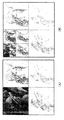
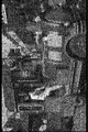
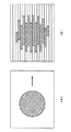
あるインタレースの動画シーンの1フレームを図22に示す。これをPCモニタ等のプログレッシブ方式のモニタで見ると、動きのある部分にインタレースの影響が強く出て、横方向に縞模様が見える。 One frame of a certain interlaced moving image scene is shown in FIG. When this is viewed on a progressive monitor such as a PC monitor, the influence of interlacing is strong on the moving part, and a striped pattern appears in the horizontal direction.
すなわち、図23(A)に示すように、丸い物体が画面中を右方向に移動する場合、インタレース画面では問題ないが、プログレッシブ画面では図23(B)のように横方向に縞模様が見えてしまう。これはインタレース画面が奇数フィールドと偶数フィールドとで飛び越し走査を用いていることに起因している。 That is, as shown in FIG. 23A, when a round object moves in the right direction on the screen, there is no problem in the interlaced screen, but in the progressive screen, a stripe pattern is formed in the horizontal direction as shown in FIG. I can see it. This is because the interlaced screen uses interlaced scanning in odd and even fields.
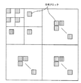
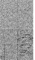
図22に示した画像を5回ウェーブレット変換・分割した後の各サブバンドの様子を図24に示す。図24から分かるように、明らかに5LH成分、すなわち水平方向が低域で垂直方向が高域である分割レベル=5のサブバンドの係数のエネルギが他のサブバンドに比べて大きくなっている。 FIG. 24 shows the state of each subband after the image shown in FIG. 22 is wavelet transformed and divided five times. As can be seen from FIG. 24, the energy of the subband coefficients of 5 LH components, that is, the division level = 5 in which the horizontal direction is the low frequency and the vertical direction is the high frequency is larger than the other subbands.
したがって、5LHのサブバンド内の符号化ブロックをそのまま符号化すれば、インタレース成分を重視した符号化が実現できることになる。 Therefore, if an encoded block in the 5LH subband is encoded as it is, encoding with an emphasis on the interlace component can be realized.
一方、プログレシブ画像表示装置に出力する場合には、5LHのサブバンド内の符号ブロックを符号化しなければよい。具体的には、5LHのサブバンド内の全ての符号ブロックのビットプレーン又は符号化パス数を0にすればよい。なお、分割レベルが最高域のLH成分に限らず、全ての分割レベルでLH成分の符号ブロックのビットプレーン又は符号化パス数を0にするようにしても構わない。 On the other hand, in the case of outputting to a progressive image display device, a code block in a 5 LH subband may not be encoded. Specifically, the number of bit planes or the number of coding passes of all code blocks in the 5LH subband may be set to zero. The division level is not limited to the LH component in the highest range, and the bit plane or the number of coding passes of the code block of the LH component may be set to 0 at all division levels.
例えば、図11に示したように、符号化対象予測部15においてサブバンド毎の全ての符号ブロックの有効ビットプレーン数の総和から符号化対象ビットプレーン数を予測する場合には、図25に示すように、5LH成分に対応する符号化対象ビットプレーン数を0に設定しておけばよい。
For example, as shown in FIG. 11, when the encoding
なお、本発明は上述した実施の形態のみに限定されるものではなく、本発明の要旨を逸脱しない範囲において種々の変更が可能であることは勿論である。 It should be noted that the present invention is not limited to the above-described embodiments, and various modifications can be made without departing from the scope of the present invention.
例えば、上述の実施の形態では、ハードウェアの構成として説明したが、これに限定されるものではなく、任意の処理を、CPU(Central Processing Unit)にコンピュータプログラムを実行させることにより実現することも可能である。この場合、コンピュータプログラムは、記録媒体に記録して提供することも可能であり、また、インターネットその他の伝送媒体を介して伝送することにより提供することも可能である。 For example, in the above-described embodiment, the hardware configuration has been described. However, the present invention is not limited to this, and arbitrary processing may be realized by causing a CPU (Central Processing Unit) to execute a computer program. Is possible. In this case, the computer program can be provided by being recorded on a recording medium, or can be provided by being transmitted via the Internet or another transmission medium.
上述した本発明によれば、例えばJPEG−2000方式の画像符号化装置において、算術符号化の処理負荷を軽減すると共に、画質劣化を抑えて効果的にレート制御を行うことができる。 According to the above-described present invention, for example, in a JPEG-2000 image coding apparatus, it is possible to reduce the processing load of arithmetic coding and to effectively perform rate control while suppressing image quality deterioration.
1 画像符号化装置、10 DCレベルシフト部、11 ウェーブレット変換部、12 量子化部、13 符号ブロック化部、14 ビットプレーン分解部、15 符号化対象予測部、16 ビットモデリング部、17 算術符号化部、18 EBCOT部、19 レート制御部、20 ヘッダ生成部、21 パケット生成部、30 有効ビットプレーン計数部、31 テーブル参照部、32 記憶部、33 符号化対象ビットプレーン抽出部、40 有効ビットプレーン計数部、41 テーブル参照部、42 記憶部、50 符号量計算制御部、51 符号量加算制御部
DESCRIPTION OF
Claims (17)
上記フィルタリング手段によって生成されたサブバンドを分割し、所定の大きさの符号ブロックを生成する符号ブロック生成手段と、
上記符号ブロック単位に最上位ビットから最下位ビットに至るビットプレーンを生成するビットプレーン生成手段と、
符号化対象となる符号化対象数を予測して符号化対象数情報を生成する符号化対象予測手段と、
上記符号化対象予測手段によって生成された上記符号化対象のうち、各符号ブロックの最上位ビット側から上記符号化対象数情報で与えられる符号化対象についてのみ、符号化を行う符号化手段と
を備え、
上記符号化対象予測手段は、上記入力画像のフレーム内の全ての符号ブロックについてゼロビットプレーンを除く有効ビットプレーン数を計数し、当該計数結果に基づいて所定のテーブルを参照することで、フレーム毎に上記符号化対象となる上記符号化対象数を求める
画像符号化装置。 Filtering means for generating a subband by applying a low-pass filter and a high-pass filter to an input image in a vertical direction and a horizontal direction, and performing a hierarchical filtering process on the subband of the low-frequency component;
Code block generation means for dividing the subband generated by the filtering means and generating a code block of a predetermined size;
Bit plane generating means for generating a bit plane from the most significant bit to the least significant bit in the code block unit;
Encoding target prediction means for predicting the encoding target number to be encoded and generating encoding target number information;
Among the encoding targets generated by the encoding target prediction means, an encoding means for performing encoding only for the encoding target given by the encoding target number information from the most significant bit side of each code block; Prepared,
The encoding target prediction means counts the number of effective bit planes excluding zero bit planes for all code blocks in the frame of the input image, and refers to a predetermined table on the basis of the counting result for each frame. An image encoding device that obtains the number of encoding objects to be encoded.
上記フィルタリング手段によって生成されたサブバンドを分割し、所定の大きさの符号ブロックを生成する符号ブロック生成手段と、
上記符号ブロック単位に最上位ビットから最下位ビットに至るビットプレーンを生成するビットプレーン生成手段と、
符号化対象となる符号化対象数を予測して符号化対象数情報を生成する符号化対象予測手段と、
上記符号化対象予測手段によって生成された上記符号化対象のうち、各符号ブロックの最上位ビット側から上記符号化対象数情報で与えられる符号化対象についてのみ、符号化を行う符号化手段と
を備え、
上記符号化対象予測手段は、上記入力画像のサブバンド内の全ての符号ブロックについてゼロビットプレーンを除く有効ビットプレーン数を計数し、当該計数結果に基づいて所定のテーブルを参照することで、サブバンド毎に符号化対象となる上記符号化対象数を求める
画像符号化装置。 Filtering means for generating a subband by applying a low-pass filter and a high-pass filter to an input image in a vertical direction and a horizontal direction, and performing a hierarchical filtering process on the subband of the low-frequency component;
Code block generation means for dividing the subband generated by the filtering means and generating a code block of a predetermined size;
Bit plane generating means for generating a bit plane from the most significant bit to the least significant bit in the code block unit;
Encoding target prediction means for predicting the encoding target number to be encoded and generating encoding target number information;
Among the encoding targets generated by the encoding target prediction means, an encoding means for performing encoding only for the encoding target given by the encoding target number information from the most significant bit side of each code block; Prepared,
The encoding target prediction unit counts the number of effective bit planes excluding zero bit planes for all code blocks in the subband of the input image, and refers to a predetermined table based on the counting result, thereby An image encoding apparatus that obtains the number of encoding targets for each band.
上記フィルタリング工程にて生成されたサブバンドを分割し、所定の大きさの符号ブロックを生成する符号ブロック生成工程と、
上記符号ブロック単位に最上位ビットから最下位ビットに至るビットプレーンを生成するビットプレーン生成工程と、
符号化対象となる符号化対象数を予測して符号化対象数情報を生成する符号化対象予測工程と、
上記符号化対象予測工程にて生成された上記符号化対象のうち、各符号ブロックの最上位ビット側から上記符号化対象数情報で与えられる上記符号化対象数についてのみ、符号化を行う符号化工程とを有し、
上記符号化対象予測工程では、上記入力画像のフレーム内の全ての符号ブロックについてゼロビットプレーンを除く有効ビットプレーン数を計数し、当該計数結果に基づいて所定のテーブルを参照することで、フレーム毎に上記符号化対象となる上記符号化対象数を求める
画像符号化方法。 A filtering step of applying a low-pass filter and a high-pass filter to the input image in a vertical direction and a horizontal direction to generate subbands, and hierarchically filtering the subbands of the low-frequency components;
A code block generation step of dividing the subband generated in the filtering step and generating a code block of a predetermined size;
A bit plane generating step for generating a bit plane from the most significant bit to the least significant bit in the code block unit;
An encoding target prediction step for predicting the encoding target number to be encoded and generating encoding target number information;
Encoding that performs encoding only for the number of encoding targets given by the number of encoding targets information from the most significant bit side of each code block among the encoding targets generated in the encoding target prediction step A process,
In the encoding target prediction step, the number of effective bit planes excluding zero bit planes is counted for all code blocks in the frame of the input image, and a predetermined table is referred to based on the counting result, so that An image encoding method for obtaining the number of encoding objects to be encoded.
上記フィルタリング工程にて生成されたサブバンドを分割し、所定の大きさの符号ブロックを生成する符号ブロック生成工程と、
上記符号ブロック単位に最上位ビットから最下位ビットに至るビットプレーンを生成するビットプレーン生成工程と、
符号化対象となる符号化対象数を予測して符号化対象数情報を生成する符号化対象予測工程と、
上記符号化対象予測工程にて生成された上記符号化対象のうち、各符号ブロックの最上位ビット側から上記符号化対象数情報で与えられる上記符号化対象数についてのみ、符号化を行う符号化工程とを有し、
上記符号化対象予測工程では、上記入力画像のサブバンド内の全ての符号ブロックについてゼロビットプレーンを除く有効ビットプレーン数を計数し、当該計数結果に基づいて所定のテーブルを参照することで、サブバンド毎に符号化対象となる上記符号化対象数を求める
画像符号化方法。 A filtering step of applying a low-pass filter and a high-pass filter to the input image in a vertical direction and a horizontal direction to generate subbands, and hierarchically filtering the subbands of the low-frequency components;
A code block generation step of dividing the subband generated in the filtering step and generating a code block of a predetermined size;
A bit plane generating step for generating a bit plane from the most significant bit to the least significant bit in the code block unit;
An encoding target prediction step for predicting the encoding target number to be encoded and generating encoding target number information;
Encoding that performs encoding only for the number of encoding targets given by the number of encoding targets information from the most significant bit side of each code block among the encoding targets generated in the encoding target prediction step A process,
In the encoding target prediction step, the number of effective bit planes excluding zero bit planes is counted for all code blocks in the subband of the input image, and a predetermined table is referred to based on the counting result, An image encoding method for obtaining the number of encoding objects to be encoded for each band.
入力画像に対して、低域フィルタ及び高域フィルタを垂直方向及び水平方向に施してサブバンドを生成し、低域成分のサブバンドに対して階層的にフィルタリング処理を施すフィルタリング工程と、
上記フィルタリング工程にて生成されたサブバンドを分割し、所定の大きさの符号ブロックを生成する符号ブロック生成工程と、
上記符号ブロック単位に最上位ビットから最下位ビットに至るビットプレーンを生成するビットプレーン生成工程と、
符号化対象となる符号化対象数を予測して符号化対象数情報を生成する符号化対象予測工程と、
上記符号化対象予測工程にて生成された上記符号化対象のうち、各符号ブロックの最上位ビット側から上記符号化対象数情報で与えられる符号化対象数についてのみ、符号化を行う符号化工程とを有し、
上記符号化対象予測工程では、上記入力画像のフレーム内の全ての符号ブロックについてゼロビットプレーンを除く有効ビットプレーン数を計数し、当該計数結果に基づいて所定のテーブルを参照することで、フレーム毎に上記符号化対象となる上記符号化対象数を求める
プログラム。 In a program for causing a computer to execute a predetermined process,
A filtering step of applying a low-pass filter and a high-pass filter to the input image in the vertical direction and the horizontal direction to generate subbands and hierarchically filtering the subbands of the low-frequency components;
A code block generation step of dividing the subband generated in the filtering step and generating a code block of a predetermined size;
A bit plane generating step for generating a bit plane from the most significant bit to the least significant bit in the code block unit;
An encoding target prediction step for predicting the encoding target number to be encoded and generating encoding target number information;
An encoding step for encoding only the number of encoding targets given by the encoding target number information from the most significant bit side of each code block among the encoding targets generated in the encoding target prediction step And
In the encoding target prediction step, the number of effective bit planes excluding zero bit planes is counted for all code blocks in the frame of the input image, and a predetermined table is referred to based on the counting result, so that A program for obtaining the number of encoding objects to be encoded.
入力画像に対して、低域フィルタ及び高域フィルタを垂直方向及び水平方向に施してサブバンドを生成し、低域成分のサブバンドに対して階層的にフィルタリング処理を施すフィルタリング工程と、
上記フィルタリング工程にて生成されたサブバンドを分割し、所定の大きさの符号ブロックを生成する符号ブロック生成工程と、
上記符号ブロック単位に最上位ビットから最下位ビットに至るビットプレーンを生成するビットプレーン生成工程と、
符号化対象となる符号化対象数を予測して符号化対象数情報を生成する符号化対象予測工程と、
上記符号化対象予測工程にて生成された上記符号化対象のうち、各符号ブロックの最上位ビット側から上記符号化対象数情報で与えられる符号化対象数についてのみ、符号化を行う符号化工程とを有し、
上記符号化対象予測工程では、上記入力画像のフレーム内の全ての符号ブロックについてゼロビットプレーンを除く有効ビットプレーン数を計数し、当該計数結果に基づいて所定のテーブルを参照することで、フレーム毎に上記符号化対象となる上記符号化対象数を求める
プログラムが記録された記録媒体。 In a computer-readable recording medium on which a program for causing a computer to execute predetermined processing is recorded,
A filtering step of applying a low-pass filter and a high-pass filter to the input image in a vertical direction and a horizontal direction to generate subbands, and hierarchically filtering the subbands of the low-frequency components;
A code block generation step of dividing the subband generated in the filtering step and generating a code block of a predetermined size;
A bit plane generating step for generating a bit plane from the most significant bit to the least significant bit in the code block unit;
An encoding target prediction step for predicting the encoding target number to be encoded and generating encoding target number information;
An encoding step of encoding only the number of encoding targets given by the encoding target number information from the most significant bit side of each code block among the encoding targets generated in the encoding target prediction step And
In the encoding target prediction step, the number of effective bit planes excluding zero bit planes is counted for all code blocks in the frame of the input image, and a predetermined table is referred to based on the counting result, so that A recording medium on which is recorded a program for determining the number of encoding targets to be encoded.
Priority Applications (1)
| Application Number | Priority Date | Filing Date | Title |
|---|---|---|---|
| JP2003351392A JP4449400B2 (en) | 2002-10-25 | 2003-10-09 | Image encoding apparatus and method, program, and recording medium |
Applications Claiming Priority (2)
| Application Number | Priority Date | Filing Date | Title |
|---|---|---|---|
| JP2002311943 | 2002-10-25 | ||
| JP2003351392A JP4449400B2 (en) | 2002-10-25 | 2003-10-09 | Image encoding apparatus and method, program, and recording medium |
Publications (3)
| Publication Number | Publication Date |
|---|---|
| JP2004166254A JP2004166254A (en) | 2004-06-10 |
| JP2004166254A5 JP2004166254A5 (en) | 2006-11-02 |
| JP4449400B2 true JP4449400B2 (en) | 2010-04-14 |
Family
ID=32828174
Family Applications (1)
| Application Number | Title | Priority Date | Filing Date |
|---|---|---|---|
| JP2003351392A Expired - Fee Related JP4449400B2 (en) | 2002-10-25 | 2003-10-09 | Image encoding apparatus and method, program, and recording medium |
Country Status (1)
| Country | Link |
|---|---|
| JP (1) | JP4449400B2 (en) |
Families Citing this family (13)
| Publication number | Priority date | Publication date | Assignee | Title |
|---|---|---|---|---|
| US20080260275A1 (en) * | 2004-05-17 | 2008-10-23 | Ikuro Ueno | Image Coding Apparatus |
| TW200746655A (en) | 2005-11-18 | 2007-12-16 | Sony Corp | Encoding device and method, decoding device and method, and transmission system |
| JP4129694B2 (en) | 2006-07-19 | 2008-08-06 | ソニー株式会社 | Information processing apparatus and method, program, and recording medium |
| US8345767B2 (en) | 2006-12-14 | 2013-01-01 | Nec Corporation | Video encoding method, video encoding device, and video encoding program |
| JP4254866B2 (en) | 2007-01-31 | 2009-04-15 | ソニー株式会社 | Information processing apparatus and method, program, and recording medium |
| JP4254867B2 (en) | 2007-01-31 | 2009-04-15 | ソニー株式会社 | Information processing apparatus and method, program, and recording medium |
| JP5162939B2 (en) | 2007-03-30 | 2013-03-13 | ソニー株式会社 | Information processing apparatus and method, and program |
| US8774283B2 (en) | 2007-03-30 | 2014-07-08 | Sony Corporation | Information processing device and method |
| JP4488027B2 (en) | 2007-05-17 | 2010-06-23 | ソニー株式会社 | Information processing apparatus and method, and information processing system |
| JP5966345B2 (en) | 2011-12-21 | 2016-08-10 | ソニー株式会社 | Image processing apparatus and method |
| JP5966346B2 (en) | 2011-12-21 | 2016-08-10 | ソニー株式会社 | Image processing apparatus and method |
| JP5966347B2 (en) | 2011-12-21 | 2016-08-10 | ソニー株式会社 | Image processing apparatus and method |
| JP5950157B2 (en) * | 2012-05-18 | 2016-07-13 | ソニー株式会社 | Image processing apparatus and method, and program |
-
2003
- 2003-10-09 JP JP2003351392A patent/JP4449400B2/en not_active Expired - Fee Related
Also Published As
| Publication number | Publication date |
|---|---|
| JP2004166254A (en) | 2004-06-10 |
Similar Documents
| Publication | Publication Date | Title |
|---|---|---|
| JP3743384B2 (en) | Image encoding apparatus and method, and image decoding apparatus and method | |
| JP4114534B2 (en) | Image coding apparatus and method | |
| JP4273996B2 (en) | Image encoding apparatus and method, and image decoding apparatus and method | |
| US7483575B2 (en) | Picture encoding apparatus and method, program and recording medium | |
| JP5034018B2 (en) | Compression encoding apparatus, compression encoding method and program | |
| JP4254017B2 (en) | Image coding apparatus and method | |
| JP3989362B2 (en) | Image processing method based on header information | |
| Walker et al. | Wavelet-based image compression | |
| JP4789148B2 (en) | Compression encoding apparatus, compression encoding method and program | |
| KR20010075232A (en) | Encoding method for the compression of a video sequence | |
| JP4449400B2 (en) | Image encoding apparatus and method, program, and recording medium | |
| JP2001501783A (en) | Data compression using adaptive bit allocation and hybrid lossless entropy coding | |
| US5737448A (en) | Method and apparatus for low bit rate image compression | |
| US20040252903A1 (en) | Method of automatically determining the region of interest from an image | |
| JP4135617B2 (en) | Image coding apparatus and method | |
| US8611686B2 (en) | Coding apparatus and method | |
| CN108810534A (en) | Method for compressing image based on direction Lifting Wavelet and improved SPIHIT under Internet of Things | |
| JP4111259B2 (en) | Encoding apparatus, encoding method, software program, table data, and recording medium | |
| JP4003628B2 (en) | Image encoding apparatus and method, and program | |
| Singh et al. | JPEG2000: A review and its performance comparison with JPEG | |
| JP4379869B2 (en) | Moving image processing apparatus, program, and information recording medium | |
| JP4379527B2 (en) | Encoding apparatus and method | |
| JP3899737B2 (en) | Image coding apparatus and method | |
| JP2005065230A (en) | Encoding apparatus, encoding control method, program and recording medium | |
| JP4367113B2 (en) | Image coding apparatus and method |
Legal Events
| Date | Code | Title | Description |
|---|---|---|---|
| A521 | Written amendment |
Free format text: JAPANESE INTERMEDIATE CODE: A523 Effective date: 20060919 |
|
| A621 | Written request for application examination |
Free format text: JAPANESE INTERMEDIATE CODE: A621 Effective date: 20060919 |
|
| A977 | Report on retrieval |
Free format text: JAPANESE INTERMEDIATE CODE: A971007 Effective date: 20090623 |
|
| A131 | Notification of reasons for refusal |
Free format text: JAPANESE INTERMEDIATE CODE: A131 Effective date: 20090804 |
|
| A521 | Written amendment |
Free format text: JAPANESE INTERMEDIATE CODE: A523 Effective date: 20090928 |
|
| A131 | Notification of reasons for refusal |
Free format text: JAPANESE INTERMEDIATE CODE: A131 Effective date: 20091020 |
|
| A521 | Written amendment |
Free format text: JAPANESE INTERMEDIATE CODE: A523 Effective date: 20091209 |
|
| TRDD | Decision of grant or rejection written | ||
| A01 | Written decision to grant a patent or to grant a registration (utility model) |
Free format text: JAPANESE INTERMEDIATE CODE: A01 Effective date: 20100105 |
|
| A01 | Written decision to grant a patent or to grant a registration (utility model) |
Free format text: JAPANESE INTERMEDIATE CODE: A01 |
|
| A61 | First payment of annual fees (during grant procedure) |
Free format text: JAPANESE INTERMEDIATE CODE: A61 Effective date: 20100118 |
|
| FPAY | Renewal fee payment (event date is renewal date of database) |
Free format text: PAYMENT UNTIL: 20130205 Year of fee payment: 3 |
|
| FPAY | Renewal fee payment (event date is renewal date of database) |
Free format text: PAYMENT UNTIL: 20130205 Year of fee payment: 3 |
|
| FPAY | Renewal fee payment (event date is renewal date of database) |
Free format text: PAYMENT UNTIL: 20140205 Year of fee payment: 4 |
|
| R250 | Receipt of annual fees |
Free format text: JAPANESE INTERMEDIATE CODE: R250 |
|
| R250 | Receipt of annual fees |
Free format text: JAPANESE INTERMEDIATE CODE: R250 |
|
| R250 | Receipt of annual fees |
Free format text: JAPANESE INTERMEDIATE CODE: R250 |
|
| R250 | Receipt of annual fees |
Free format text: JAPANESE INTERMEDIATE CODE: R250 |
|
| LAPS | Cancellation because of no payment of annual fees |