JP6857970B2 - Image coding device and its control method - Google Patents
Image coding device and its control method Download PDFInfo
- Publication number
- JP6857970B2 JP6857970B2 JP2016110223A JP2016110223A JP6857970B2 JP 6857970 B2 JP6857970 B2 JP 6857970B2 JP 2016110223 A JP2016110223 A JP 2016110223A JP 2016110223 A JP2016110223 A JP 2016110223A JP 6857970 B2 JP6857970 B2 JP 6857970B2
- Authority
- JP
- Japan
- Prior art keywords
- plane
- subband
- difference
- code amount
- cur
- Prior art date
- Legal status (The legal status is an assumption and is not a legal conclusion. Google has not performed a legal analysis and makes no representation as to the accuracy of the status listed.)
- Active
Links
Images


Classifications
-
- H—ELECTRICITY
- H04—ELECTRIC COMMUNICATION TECHNIQUE
- H04N—PICTORIAL COMMUNICATION, e.g. TELEVISION
- H04N19/00—Methods or arrangements for coding, decoding, compressing or decompressing digital video signals
- H04N19/10—Methods or arrangements for coding, decoding, compressing or decompressing digital video signals using adaptive coding
- H04N19/102—Methods or arrangements for coding, decoding, compressing or decompressing digital video signals using adaptive coding characterised by the element, parameter or selection affected or controlled by the adaptive coding
- H04N19/124—Quantisation
-
- H—ELECTRICITY
- H04—ELECTRIC COMMUNICATION TECHNIQUE
- H04N—PICTORIAL COMMUNICATION, e.g. TELEVISION
- H04N19/00—Methods or arrangements for coding, decoding, compressing or decompressing digital video signals
- H04N19/10—Methods or arrangements for coding, decoding, compressing or decompressing digital video signals using adaptive coding
- H04N19/134—Methods or arrangements for coding, decoding, compressing or decompressing digital video signals using adaptive coding characterised by the element, parameter or criterion affecting or controlling the adaptive coding
- H04N19/146—Data rate or code amount at the encoder output
-
- H—ELECTRICITY
- H04—ELECTRIC COMMUNICATION TECHNIQUE
- H04N—PICTORIAL COMMUNICATION, e.g. TELEVISION
- H04N19/00—Methods or arrangements for coding, decoding, compressing or decompressing digital video signals
- H04N19/10—Methods or arrangements for coding, decoding, compressing or decompressing digital video signals using adaptive coding
- H04N19/169—Methods or arrangements for coding, decoding, compressing or decompressing digital video signals using adaptive coding characterised by the coding unit, i.e. the structural portion or semantic portion of the video signal being the object or the subject of the adaptive coding
- H04N19/186—Methods or arrangements for coding, decoding, compressing or decompressing digital video signals using adaptive coding characterised by the coding unit, i.e. the structural portion or semantic portion of the video signal being the object or the subject of the adaptive coding the unit being a colour or a chrominance component
-
- H—ELECTRICITY
- H04—ELECTRIC COMMUNICATION TECHNIQUE
- H04N—PICTORIAL COMMUNICATION, e.g. TELEVISION
- H04N19/00—Methods or arrangements for coding, decoding, compressing or decompressing digital video signals
- H04N19/42—Methods or arrangements for coding, decoding, compressing or decompressing digital video signals characterised by implementation details or hardware specially adapted for video compression or decompression, e.g. dedicated software implementation
- H04N19/436—Methods or arrangements for coding, decoding, compressing or decompressing digital video signals characterised by implementation details or hardware specially adapted for video compression or decompression, e.g. dedicated software implementation using parallelised computational arrangements
-
- H—ELECTRICITY
- H04—ELECTRIC COMMUNICATION TECHNIQUE
- H04N—PICTORIAL COMMUNICATION, e.g. TELEVISION
- H04N19/00—Methods or arrangements for coding, decoding, compressing or decompressing digital video signals
- H04N19/60—Methods or arrangements for coding, decoding, compressing or decompressing digital video signals using transform coding
- H04N19/63—Methods or arrangements for coding, decoding, compressing or decompressing digital video signals using transform coding using sub-band based transform, e.g. wavelets
Description
本発明は、画像データの符号化技術に関するものである。 The present invention relates to an image data coding technique.
現在、デジタルビデオカメラ等、動画像を記録するデジタル機器が普及しており、近年では静止画にのみ適用されていたRAW画像記録が動画像の記録にも適用されている。上記のRAW画像は記録に必要なデータ量が膨大になるものの、オリジナル画像に対する補正や劣化を最低限に抑えられる点、撮影後の画像編集の自由度が高い点等から、撮像装置を使用する者の中でも上級者によって好んで使われている。 Currently, digital devices such as digital video cameras for recording moving images have become widespread, and in recent years, RAW image recording, which has been applied only to still images, has also been applied to recording moving images. Although the amount of data required for recording the above RAW image is enormous, an image pickup device is used because correction and deterioration of the original image can be minimized and the degree of freedom in image editing after shooting is high. It is used favorably by advanced users.
RAW動画像をメモリカード等の記録媒体に記録するためには、その記録媒体の容量に応じた時間分の記録を可能とするため、或る程度の圧縮率でRAW動画像を圧縮符号化することが必要になる。 In order to record a RAW moving image on a recording medium such as a memory card, the RAW moving image is compressed and coded at a certain compression rate in order to enable recording for a time corresponding to the capacity of the recording medium. Is needed.
一般に、撮像素子はベイヤ配列を採用している。ベイヤ配列は、異なる色成分が交互に並んでいることから、隣接する画素間の相関が低く、そのまま符号化しても圧縮効率が悪い。そこで、ベイヤ配列の画像データから、R成分のみの画像プレーン、G1成分のみの画像プレーン、G2成分のみの画像プレーン、B成分のみの画像プレーンに分離し、プレーン毎に符号化を行うことで、符号化効率を向上させることが行われている。 Generally, the image pickup device adopts a Bayer array. In the Bayer array, since different color components are arranged alternately, the correlation between adjacent pixels is low, and even if the Bayer array is encoded as it is, the compression efficiency is poor. Therefore, the image data of the Bayer array is separated into an image plane containing only the R component, an image plane containing only the G1 component, an image plane containing only the G2 component, and an image plane containing only the B component, and coding is performed for each plane. The coding efficiency has been improved.
また、従来の代表的な圧縮符号化方式として、H.264(H.264/ MPEG-4 Part10 : Advanced Video Coding)が知られている。かかる圧縮符号化方式では、1フレーム内で所定画素数から成るブロック毎に、動画像が有する時間冗長性と空間冗長性を利用してデータ量を圧縮する。 Further, as a conventional typical compression coding method, H.I. 264 (H.264 / MPEG-4 Part10: Advanced Video Coding) is known. In such a compression coding method, the amount of data is compressed by utilizing the time redundancy and spatial redundancy of the moving image for each block consisting of a predetermined number of pixels in one frame.
上記H.264では、時間冗長性に対する動き検出及び動き補償、空間冗長性に対する周波数変換として離散コサイン変換(Discrete Cosine Transform;DCT) 、更に量子化やエントロピー符号化といった技術を組み合わせている。ただし、ある程度以上圧縮率を上げると、DCT変換特有のブロック歪みが顕著になり、主観的に画像劣化が目立つようになる。 The above H. In 264, the time the motion detection and motion compensation for redundancy, a discrete cosine transform as the frequency conversion for the spatial redundancy (D i screte Cosine Transform; DCT ), further combining technologies such as quantization and entropy coding. However, if the compression ratio is increased to some extent or more, the block distortion peculiar to the DCT transform becomes remarkable, and the image deterioration becomes subjectively noticeable.
そこで、周波数変換として、水平方向と垂直方向に低域フィルタリングと高域フィルタリングをそれぞれかけることで、サブバンドと呼ばれる周波数帯に分解する技術がJPEG2000で採用されている。JPEG2000では、周波数帯へ周波数変換を行うために離散ウェーブレット変換(Discrete Wavelet Transform; 以下、DWT)を用いている。サブバンド符号化は、DCTを用いた符号化技術に比べ、ブロック歪みが生じにくく、高圧縮時の圧縮特性が良いといった特徴を有する。 Therefore, as frequency conversion, JPEG2000 employs a technique of decomposing into a frequency band called a sub-band by applying low-frequency filtering and high-frequency filtering in the horizontal and vertical directions, respectively. In JPEG2000, a Discrete Wavelet Transform (DWT) is used to perform frequency conversion to a frequency band. Subband coding is characterized in that block distortion is less likely to occur and compression characteristics at the time of high compression are good as compared with a coding technique using DCT.
以上のような技術に加えて、所望の符号化レート(圧縮率)で符号化する符号量制御が行われる。一般的な符号量制御は、符号化が完了しているフレームの情報を元に、次に符号化するフレームの目標符号量を決定するものである。そして1フレームあたりの目標符号量へ発生符号量を収束させるため、符号量差分(発生符号量から目標符号量を減じることで算出される値)の絶対値が小さくなるように、量子化に利用する量子化パラメータQpの制御を行う。この量子化パラメータの制御は、画像の所定の領域毎に逐次行われる。なお、Qpは、その値が大きい程符号量を削減することができるパラメータである一方、画質劣化の原因になる。そのため、この量子化パラメータQpは可能な限り小さく、かつ画面内で一定であることが望ましいパラメータであると言える。 In addition to the above techniques, code amount control for coding at a desired coding rate (compression rate) is performed. In general code amount control, the target code amount of the frame to be encoded next is determined based on the information of the frame in which the coding is completed. Then, in order to converge the generated code amount to the target code amount per frame, it is used for quantization so that the absolute value of the code amount difference (value calculated by subtracting the target code amount from the generated code amount) becomes small. The quantization parameter Qp is controlled. The control of the quantization parameter is sequentially performed for each predetermined region of the image. The larger the value of Qp, the more the code amount can be reduced, but on the other hand, it causes deterioration of image quality. Therefore, it can be said that it is desirable that the quantization parameter Qp is as small as possible and constant in the screen.
上述のプレーン変換、サブバンド符号化を組み合わせた場合、入力画像をプレーン変換し、各プレーンに対してDWTを施すことで、各サブバンド毎に符号量制御ができる。フレームの目標符号量を、各サブバンドへサブバンド目標符号量として分配し、サブバンド毎に量子化制御を行うことで、量子化制御を行うことができ、所望の符号量へ画像データを圧縮することが可能である。また、上述の各プレーンや、各サブバンド間のQpの比率を所定の関係にすることで画質を向上させることができる。例えば、プレーン変換により生成されたR,G(G1,G2),B各プレーンは、視覚的重要度が同等であるという観点から、同じQpであることが望ましい。更に、各サブバンド間のQpの関係は、高域サブバンドほど量子化パラメータを大きく設定することが望ましい。上述のサブバンド間のQp設定の関係式は、JPEG2000で暗示的な量子化としても規定されている。 When the above-mentioned plane conversion and sub-band coding are combined, the code amount can be controlled for each sub-band by plane-converting the input image and applying DWT to each plane. Quantization control can be performed by distributing the target code amount of the frame to each subband as a subband target code amount and performing quantization control for each subband, and compressing image data to a desired code amount. It is possible to do. Further, the image quality can be improved by setting the ratio of Qp between each of the above planes and each subband to a predetermined relationship. For example, it is desirable that the R, G (G1, G2), and B planes generated by the plane conversion have the same Qp from the viewpoint of having the same visual importance. Furthermore, regarding the relationship of Qp between each subband, it is desirable to set the quantization parameter larger for higher subbands. The above-mentioned relational expression of Qp setting between subbands is also defined in JPEG2000 as implicit quantization.
しかしながら、プレーン毎やサブバンド毎に独立に量子化制御を行うと、各プレーンや各サブバンドで符号量制御した際に生じる符号量差分が、各プレーンや各サブバンドで融通できないため、符号量制御性が低下する場合がある。 However, if the quantization control is performed independently for each plane or subband, the code amount difference generated when the code amount is controlled for each plane or each subband cannot be accommodated in each plane or each subband, so that the code amount cannot be accommodated. Controllability may decrease.
また、初期設定値として各サブバンドに設定するQpは、プレーン間及びサブバンド間のQpの関係が所定の関係になるように設定することができる。しかし、プレーン毎やサブバンド毎に独立に量子化制御をすれば、当該フレームの符号化途中で量子化制御によりQpの関係が所定の関係から逸脱していく場合が生じる。 Further, the Qp set for each sub-band as the initial setting value can be set so that the relationship between the planes and the Qp between the sub-bands has a predetermined relationship. However, if the quantization control is performed independently for each plane or each subband, the Qp relationship may deviate from the predetermined relationship due to the quantization control during the coding of the frame.
そこで、予め色差成分及び輝度成分の各々に発生符号量の上限値を定め、色差成分の符号化で余った符号量を輝度成分の発生符号量の上限値に加算することで、符号量制御性を向上させる技術が特許文献1に記載されている。
Therefore, the upper limit value of the generated code amount is set in advance for each of the color difference component and the luminance component, and the code amount surplus from the coding of the color difference component is added to the upper limit value of the generated code amount of the luminance component to control the code amount. A technique for improving the above is described in
特許文献1によれば、画像を色差成分と輝度成分に変換すると共にブロック単位で分割し、ブロック毎に符号化を行う際に、色差成分の符号化を先に実施する。そして、色差成分に割り当てた目標符号量に対して、符号が余ったら輝度の符号量上限値を増加させることで、コンポーネント間で符号を融通した符号量制御を行うことができる。
According to
しかしながら、特許文献1に記載された技術では、符号量制御性は向上するものの、画質が劣化する場合がある。符号量上限値を、所定ブロックの目標符号量と置き換えると、R,G,Bプレーン間で適応した場合、符号量が余ったから一方のプレーンのQpだけ変更するような制御が行われることで、プレーン間のQpの関係は所定の関係から逸脱するからである
例えばR,G,Bプレーンへ分解した各プレーンにおいて、Rプレーンの符号量が大きく、Bプレーンの符号量が小さい場合に、RプレーンのQpを大きく、BプレーンのQpを小さくするように符号量制御を行う。この場合、原画像に対して符号化後の赤成分の情報比率は減ってしまい、符号量の制御が出来ても、結果的に画質が劣化する。
However, in the technique described in
それ故、画質の高い符号化を行うには、フレーム目標符号量にフレーム発生符号量が収束し、かつプレーン間のQpが同じになるように量子化制御を実施することが望ましいことが理解できよう。 Therefore, in order to perform high-quality coding, it can be understood that it is desirable to perform quantization control so that the frame generation code amount converges on the frame target code amount and the Qp between planes is the same. Yeah.
本発明は上記の問題点に鑑みなされたものであり、RAW動画像記録を、各色成分のプレーン間でアンバランスとならず、高い品位を維持して符号量制御を行う技術を提供しようとするものである。 The present invention has been made in view of the above problems, and an object of the present invention is to provide a technique for controlling the amount of code while maintaining high quality in RAW moving image recording without imbalance between planes of each color component. It is a thing.
この課題を解決するため、例えば本発明の画像符号化装置は以下の構成を備える。すなわち、
撮像部で撮像した動画像データを符号化する画像符号化装置であって、
前記動画像データの1フレームの画像データから、それぞれが単一成分で構成される複数のプレーンのプレーンデータを生成するプレーン変換手段と、
生成した各プレーンデータに対して周波数変換し、プレーン毎に、複数のサブバンドの係数データを生成する周波数変換手段と、
量子化パラメータを用いて、サブバンド毎に係数データを量子化する量子化手段と、
量子化後の係数データを符号化し、符号化データを生成する符号化手段と、
前記符号化手段で生成される符号化データの発生符号量が、設定された目標符号量となるように、量子化パラメータを制御する制御手段とを有し、
前記制御手段は、
プレーン毎に設定された目標符号量と、各プレーンの符号化データの発生符号量との差分から、前記複数のプレーンの差分の総量を算出し、
前記差分の総量を前記複数のプレーンに分配し、
各プレーンについて、プレーンに分配された発生符号量の差分に対応する値を量子化パラメータに加算して、前記量子化パラメータを更新することを特徴とする。
In order to solve this problem, for example, the image coding apparatus of the present invention has the following configuration. That is,
An image coding device that encodes moving image data captured by the imaging unit.
A plane conversion means for generating plane data of a plurality of planes, each of which is composed of a single component, from one frame of image data of the moving image data.
A frequency conversion means that converts the frequency of each generated plane data and generates coefficient data of a plurality of subbands for each plane.
A quantization means that quantizes coefficient data for each subband using quantization parameters,
A coding means that encodes the quantized coefficient data and generates the coded data,
It has a control means for controlling the quantization parameter so that the generated code amount of the coded data generated by the coding means becomes the set target code amount.
The control means
From the difference between the target code amount set for each plane and the generated code amount of the coded data of each plane, the total amount of the differences of the plurality of planes is calculated.
The total amount of the difference is distributed to the plurality of planes, and the difference is distributed to the plurality of planes.
For each plane, the value corresponding to the difference generated code amount distributed to the plane by adding the quantization parameter, and updates the quantization parameter.
本発明によれば、RAW動画像データから生成した各成分のプレーンを符号化する際に、個々のプレーンを互いに関連する量子化パラメータに従って量子化することで、これまでよりも高画質となる符号化データを生成することが可能となる。 According to the present invention, when encoding the planes of each component generated from RAW moving image data, the individual planes are quantized according to the quantization parameters related to each other, so that the image quality becomes higher than before. It is possible to generate the quantized data.
以下図面を参照しながら本発明の好適な実施の形態を説明する。 A preferred embodiment of the present invention will be described below with reference to the drawings.
[第1の実施形態]
<装置構成>
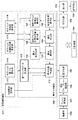
図1は、第1の実施形態が適用する画像符号化装置のブロック構成図である。この画像符号化装置は、デジタルビデオカメラなどの撮像装置に適用されるものでもある。
[First Embodiment]
<Device configuration>
FIG. 1 is a block configuration diagram of an image coding device to which the first embodiment is applied. This image coding device is also applied to an imaging device such as a digital video camera.
図示において符号150は、装置全体の制御を司る主制御部であり、以下の説明する各種処理部の制御を司る。
In the figure,
撮像部100は、光学レンズ、ベイヤ配列の撮像素子、A/D変換器等を収容し、撮像したRAW形式の動画像データをフレーム単位にプレーン変換部101に供給する。ベイヤ配列では、その中の2×2画素が1個のR(レッド)画素、1個のB(ブルー)画素、2つのG(グリーン)画素で構成される。2つのG画素は、それぞれを区別するため、一般にG1,G2と表記されることが多い。また、実施形態における撮像部100は、例えば1秒当たり30枚のRAW画像データをプレーン変換部101に供給するものとする。
The
プレーン変換部101は、入力した1枚のRAW画像データから、それぞれが単一成分の4つのプレーンデータを生成する。ここでは、実施形態では、Rプレーン、G1プレーン、G2プレーン、Bプレーンの4プレーンに生成され、離散ウェーブレット変換部102に供給される。図2は、入力したRAW画像データ(ベイヤ配列)と、R,G1,G2,Bの4プレーンとの関係を示している。プレーン変換部101による4つのプレーンへ分離し、圧縮符号化を実施することで、ベイヤ配列の画像に比べ、プレーン内の画素間の相関を高め、圧縮効率を向上させることができる。
The
離散ウェーブレット変換部102は、入力した1つのプレーン(R,G1,G2,Bプレーンのいずれか)が示す画像データに対し離散ウェーブレット変換(以下、DWT)を行う。この結果、複数のサブバンドの係数データ(周波数領域信号)が生成されるので、離散ウェーブレット変換部102はそれらを出力する(詳細後述)。
The discrete
なお、実施形態におけるプレーン変換部101は1枚のRAW画像データから4つのプレーンが生成されている。DWTに係る時間の短縮のために離散ウェーブレット変換部102を4つ並列に配置して、DWTを並列実行しても良い。これは、後述する量子化部103、符号化部104でも同様である。
The
また、DWTは、一般に画像全体に対してフィルタリングを行うが、フィルタタップ数分の画素がメモリに溜まったタイミングで、垂直方向及び水平方向のフィルタリングを行うことが可能である。そのため、DWTを入力画像の1ライン単位に行い、更に生成された低域サブバンド(一般にLLサブバンド)に対して再帰的にDWTを行うことで、各サブバンドをライン単位に並列に処理することが可能である。 Further, although the DWT generally filters the entire image, it is possible to perform filtering in the vertical direction and the horizontal direction at the timing when pixels corresponding to the number of filter taps are accumulated in the memory. Therefore, by performing DWT in units of one line of the input image and recursively performing DWT for the generated low-frequency subbands (generally LL subbands), each subband is processed in parallel in line units. It is possible.
離散ウェーブレット変換部102は、周波数変換で得られた各プレーンの各サブバンドの係数データをライン単位に順次量子化部103へ供給する。
The discrete
量子化制御部105は、ライン単位で入力した係数データを、符号量制御部117より設定された量子化パラメータQpを量子化部103に設定する。符号量制御部117はライン単位に量子化パラメータQpを更新する。量子化部103はライン単位に更新される量子化パラメータQpに従って着目ラインを構成する各係数データを量子化しては、その量子化後の係数データを符号化部104に供給することになる。量子化パラメータQpは、その値が大きいほど符号量を削減することが可能であるが、その一方で、その値が大きいほど画質が劣化するパラメータである。
The
符号化部104は、量子化部103から供給された量子化後の係数データを符号化して符号化データを生成し、出力部119に供給する。出力部119は、符号化部104から供給された符号化データに、復号に必要な情報を含むヘッダを付加し、所定のフォーマットの符号化データを生成し、記憶媒体120に書き込む。
The
次に第1の実施形態にける符号量制御部117について説明する。
Next, the code
符号量制御部117は、制御感度設定部113、サブバンド量子化設定部114、サブバンド目標符号量設定部115、そしてサブバンド複雑度設定部116を含み、これらによりサブバンド毎の各種設定値を元にした符号量の制御を行う。なお、上記の各種設定値は、前のフレームの符号化情報を元にフィードバック制御で算出するものである。
The code
量子化制御部105は、発生符号量が目標符号量に収束するように、サブバンド毎に予め設定された矩形ブロック単位にQpを制御する。実施形態における、この矩形ブロックはサブバンドの1ラインとする。
The
また、本実施形態では、各プレーン、各サブバンドのQpの関係が、後述する所定のQpの関係になるように量子化制御を実施することを目的としている。このため、量子化制御部105は、R,G1,G2,Bの各プレーンに対して、同一係数データの位置に相当する各サブバンドのラインを順次処理する。
Further, in the present embodiment, it is an object of the present embodiment to carry out the quantization control so that the relationship of Qp of each plane and each subband becomes the relationship of predetermined Qp described later. Therefore, the
発生符号量保持部106は、符号化部104から通知される符号化データである、発生符号量をサブバンド毎に保持する。
The generated code
変数iを符号化対象ラインのライン番号とすると、矩形ブロック複雑度算出部107は、着目サブバンドにおける、後続して符号化される第iラインに備えて、1ライン前のラインの複雑度X[i−1]を算出する(詳細後述)。
Assuming that the variable i is the line number of the line to be coded, the rectangular block
矩形ブロック複雑度算出部107で算出されたライン毎の複雑度は、サブバンド毎に積算(合算)され、サブバンド複雑度設定部116で保持される。矩形ブロック目標符号量算出部108は、サブバンド目標符号量設定部115で設定されるサブバンド目標符号量Tsb、サブバンド複雑度設定部116で設定されるサブバンド複雑度Xsb、矩形ブロック複雑度算出部107で算出されるライン複雑度X[i−1]に従い、着目サブバンドのライン目標符号量T[i−1]を算出する(詳細後述)。
The complexity of each line calculated by the rectangular block
差分算出部109は、着目サブバンドのライン毎に、発生符号量保持部106で保持された着目ラインからの発生符号量S[i−1]と、矩形ブロック目標符号量算出部108から出力されるライン目標符号量T[i−1]の差分値E[i−1]を算出する。
The
差分保持部110は、この算出値E[i−1]を積算した積算差分値ΣE[i−1]をサブバンド毎に保持する。ここで、着目サブバンドの目標符号量Ttarget、着目サブバンドが含むライン数をMとし、水平軸をライン数、垂直軸を符号量と定義する座標空間を定義したとする。積算差分値ΣE[i−1]は、原点(0,0)と(M、Ttarget)とを結ぶ理想とする符号量推移線上から、どれだけずれているかを示していることになる。
The
差分再算出部118は、差分保持部110で保持しているサブバンド毎の積算差分値ΣE[i−1]を用いて、量子化値算出部111でQpの決定に利用する再算出符号量差分値Ereを算出する(詳細後述)。
The
量子化値算出部111は、差分再算出部118から通知された再算出符号量差分値Ereと、サブバンド量子化設定部114で設定され、量子化パラメータ保持部112で保持されている初期QpであるQp[0]、そして、制御感度設定部113で設定される制御感度rを用いて、着目サブバンド内の次のラインの量子化パラメータQp[i]を決定する。この量子化パラメータQp[i]は、着目ラインまでの発生符号量積算量が、同目標符号量積算量へ近付くように算出される(詳細後述)。以上が実施形態における符号量制御部117の概ねの処理内容である。
The quantization
<離散ウェーブレット変換(DWT)>
図3は、DWTの垂直、水平フィルタリング処理をそれぞれ三回施した、分解レベル3の場合のサブバンド形成図である。
<Discrete Wavelet Transform (DWT)>
FIG. 3 is a subband formation diagram in the case of decomposition level 3 in which the vertical and horizontal filtering processing of the DWT is performed three times each.
DWTは、垂直、水平にそれぞれフィルタをかけることでHH,HL,LH,LLの4つの周波数帯域(サブバンド)の係数データを生成する。そして、上記変換により生成された低域(LL)サブバンドに対して再帰的にDWTを施すことで分解レベルを増加させ、図3のように周波数分解の粒度を細かくすることができる。なお、図3における“L”,“H”はそれぞれ低域、高域を示し、その順序は、前側が水平フィルタリングを行った結果の帯域、後側が垂直フィルタリングを行った結果の帯域を示し、“Lv”の後の数字はDWTの分解レベルを示す。また、LLは、最低域サブバンドを示す。 The DWT generates coefficient data of four frequency bands (sub-bands) of HH, HL, LH, and LL by filtering vertically and horizontally, respectively. Then, by recursively applying DWT to the low frequency (LL) subband generated by the above conversion, the decomposition level can be increased and the particle size of frequency decomposition can be made finer as shown in FIG. In addition, "L" and "H" in FIG. 3 indicate a low region and a high region, respectively, and the order thereof indicates a band resulting from horizontal filtering on the front side and a band resulting from vertical filtering on the rear side. The number after "Lv" indicates the decomposition level of DWT. Further, LL indicates the lowest subband.
図1の符号量制御部117では、高域のサブバンドほど量子化パラメータを大きく、低域のサブバンドほど量子化パラメータを小さく設定し符号量制御を行う。これにより人間の視覚特性上視認しづらい、画像データの高域成分ほど発生符号量を圧縮し、符号化効率を向上させる。
In the code
<複雑度の算出>
複雑度は、画像の符号化の難易度を示す指標であり、画像が難しいほど大きく、易しいほど小さいパラメータである。難しい画像とは、あるQpで画像全面を符号化したときに、発生する符号量が多いことを示すものである。故に、複雑度Xは、量子化パラメータQp、発生符号量Sを用いて、次式(1)のように表す。
X=Qp×S …(1)
<Calculation of complexity>
The complexity is an index indicating the difficulty of coding an image, and is a parameter that is larger as the image is more difficult and smaller as the image is easier. A difficult image indicates that a large amount of code is generated when the entire image is encoded with a certain Qp. Therefore, the complexity X is expressed by the following equation (1) using the quantization parameter Qp and the generated code amount S.
X = Qp × S ... (1)
矩形ブロック複雑度算出部107は、矩形ブロック目標符号量を算出するために、次に符号化する着目ラインに対して、1ライン前のラインの複雑度Xを算出する。
The rectangular block
1ライン前の符号化に利用した量子化パラメータをQp[i-1]と表し、その際の発生符号量S[i-1]としたとき、1ライン前の複雑度X[i-1]は、式(1)に従って次式(2)のように表せる。
X[i-1]=Qp[i-1]×S[i-1] …(2)
When the quantization parameter used for coding one line before is expressed as Qp [i-1] and the amount of code generated at that time is S [i-1], the complexity X [i-1] one line before. Can be expressed as the following equation (2) according to the equation (1).
X [i-1] = Qp [i-1] × S [i-1]… (2)
<矩形ブロック目標符号量の算出>
各サブバンドでは、画像の難しいラインほど目標符号量を多く割り当て、易しいラインほど目標符号量を小さく割り当てることで、Qpの変動を、サブバンド内で極力小さくすることができる。
<Calculation of rectangular block target code amount>
In each sub-band, the fluctuation of Qp can be minimized within the sub-band by allocating a larger target code amount to a difficult line in the image and allocating a smaller target code amount to an easy line.
そこで、矩形ブロック目標符号量算出部108は、サブバンド目標符号量設定部115で設定されるサブバンド目標符号量Tsb、サブバンド複雑度設定部116で設定されるサブバンド複雑度Xsb及び、矩形ブロック複雑度X[i-1]に従い、着目サブバンド内の次に符号化するラインの目標符号量T[i-1]を次式(3)に基づき算出する。
T[i-1] = Tsb × X[i-1] / Xsb_{N-1} …(3)
式(1)で示したように、複雑度は発生符号量を利用し算出するため、符号化しなければ得られないフィードバック量である。そのため、Xsbには、着目フレームであるNフレームに対して、1フレーム前のサブバンド複雑度Xsb_{N-1}をフィードバックし用いる。ただし、Nは整数で有り、Nフレームは着目RAW画像データを表す。
Therefore, the rectangular block target code
T [i-1] = Tsb × X [i-1] / Xsb_ {N-1}… (3)
As shown in the equation (1), the complexity is calculated by using the generated code amount, so that it is a feedback amount that cannot be obtained without coding. Therefore, for Xsb, the subband complexity Xsb_ {N-1} one frame before is fed back and used with respect to the N frame which is the frame of interest. However, N is an integer, and the N frame represents the RAW image data of interest.
式(3)の如く、サブバンド全体に対する着目ラインの複雑度の比率をTsbに乗ずることで、難しいラインでは目標符号量を多く割り当て、易しいラインでは目標符号量を少なく割り当てることができる。この結果、サブバンド内でQpの変動を極力小さくすることができる。 By multiplying Tsb by the ratio of the complexity of the line of interest to the entire subband as in equation (3), it is possible to allocate a large amount of target code for difficult lines and a small amount of target code for easy lines. As a result, the fluctuation of Qp in the subband can be minimized.
<量子化制御>
量子化パラメータ算出方法の一つに、「MPEG2 Test Model 5」に示された公知技術がある。この技術に従い、差分保持部110に保持された積算差分値ΣE[i-1]と量子化パラメータ保持部112に保持された初期量子化パラメータQp[0]、制御感度設定部113で設定された制御感度rを用いて、着目サブバンド内の次のラインの量子化パラメータQp[i]を次式(4)のように算出できる。
Qp[i]=Qp[0] + r ×ΣE[i-1] …(4)
なお、制御感度rは、大きいほど再算出符号量差分値に応じて急峻にQp[i]を変動させる一方、符号量の制御性が良くなるパラメータである。
<Quantization control>
As one of the methods for calculating the quantization parameter, there is a known technique shown in "MPEG2 Test Model 5". According to this technique, the integrated difference value ΣE [i-1] held in the
Qp [i] = Qp [0] + r × ΣE [i-1]… (4)
The control sensitivity r is a parameter that sharply fluctuates Qp [i] according to the recalculated code amount difference value as the value increases, while improving the controllability of the code amount.
本第1の実施形態では、積算差分値ΣE[i-1]の代わりに、差分再算出部118から通知された再算出符号量差分値Ereを用いて、次式(5)のように算出することで、後述する所定のQpの関係を満たす制御を行う。
Qp[i]=Qp[0] + r ×Ere …(5)
「MPEG2 Test Model 5」を利用することで、目標符号量に対して発生符号量が大きければ量子化パラメータを大きく、小さければ量子化パラメータを小さく設定し、符号量を制御することが可能である。
In the first embodiment, instead of the integrated difference value ΣE [i-1], the recalculated code amount difference value Ere notified from the
Qp [i] = Qp [0] + r × Ere… (5)
By using "MPEG2 Test Model 5", if the generated code amount is large with respect to the target code amount, the quantization parameter is set large, and if it is small, the quantization parameter is set small, and the code amount can be controlled. ..
<符号量制御:RGBプレーン間における量子化パラメータの所定の関係>
図2で示すR,G1,G2,Bプレーンへの変換により生成された各プレーンは、人間の視覚特性上の重要度に差はなく、どのプレーンに優劣を付けることなく一律で重要なプレーンといえる。なお、G1,G2プレーンは同じ量子化パラメータによる符号化を行うので、以下ではG1プレーンを単にGプレーンと表記することとする。
<Code amount control: Predetermined relationship of quantization parameters between RGB planes>
The planes generated by the conversion to the R, G1, G2, and B planes shown in FIG. 2 have no difference in importance in terms of human visual characteristics, and are uniformly important planes regardless of which plane is superior or inferior. I can say. Since the G1 and G2 planes are coded by the same quantization parameters, the G1 plane will be simply referred to as the G plane below.
量子化パラメータQpは、どのプレーンでも互いに等しいことが望ましいことは既に説明した。以降、プレーン間やサブバンド間で望ましいQpの関係を、所定のQpの関係と記す。 It has already been explained that the quantization parameters Qp should be equal to each other in all planes. Hereinafter, the desirable Qp relationship between planes and subbands will be referred to as a predetermined Qp relationship.
ここで、各サブバンドの積算差分値をそのまま用いて量子化制御を実施した場合の問題について説明する。 Here, a problem will be described when quantization control is performed using the integrated difference value of each subband as it is.
図4(a)は、或る着目サブバンドにおいて、Rプレーンでは目標符号量に対し発生符号量が多く、G1、G2プレーンでは目標符号量上を推移し、Bプレーンでは目標符号量に対して発生符号量が少ない場合の、従来の量子化制御の一例を示す図である。図4(b)は、図4(a)における各プレーンの着目サブバンド内のQpの推移を示した図である。 FIG. 4A shows that in a certain subband of interest, the generated code amount is larger than the target code amount in the R plane, the code amount is higher than the target code amount in the G1 and G2 planes, and the target code amount is in the B plane. It is a figure which shows an example of the conventional quantization control when the generated code amount is small. FIG. 4B is a diagram showing the transition of Qp in the subband of interest of each plane in FIG. 4A.
従来の量子化制御は、各プレーンのサブバンドを独立して量子化制御を実施している。図1において、差分再算出部118で各色プレーン毎に、再算出する再算出符号量差分値Ere=ΣE[i-1]としたときの動作のことを示す。
In the conventional quantization control, the subband of each plane is independently quantized. FIG. 1 shows an operation when the recalculated code amount difference value Ere = ΣE [i-1] to be recalculated for each color plane by the
サブバンド目標符号量は、フィードバック制御等を利用し予測した値であるため、必ずしも正しい設定値とは限らない。なお、ここで述べる正しい設定とは、積算差分値が発生せず、Qpが全ラインを通して初期Qpから変化しない設定をした場合を指す。 Since the sub-band target code amount is a value predicted by using feedback control or the like, it is not always the correct set value. The correct setting described here refers to a case where the integrated difference value does not occur and the Qp does not change from the initial Qp throughout the entire line.
図4(a)に示すRプレーンのように各ラインの目標符号量積算量に対して着目サブバンドのライン発生符号量積算量が大きければ、Qpを大きくすることで発生符号量を抑え込もうと量子化制御が働く。また、ラインの目標符号量積算量に対して着目サブバンドのライン発生符号量積算量が小さければ、Qpを小さくすることで発生符号量を増やそうと量子化制御が働く。このため、Qpがプレーン間でばらばらになり、「所定のQpの関係」から逸脱する場合がある。この場合、符号量は予め設定したフレーム目標符号量に収束するものの、各プレーン間でばらばらなQpとなってしまい、「所定のQpの関係」を保つ制御を実施した場合と比較して画質の劣化が大きい。 If the line generation code amount integration amount of the subband of interest is large with respect to the target code amount integration amount of each line as in the R plane shown in FIG. 4A, increase the Qp to suppress the generation code amount. And quantization control works. Further, if the line generation code amount integration amount of the subband of interest is smaller than the line target code amount integration amount, the quantization control works to increase the generation code amount by reducing Qp. Therefore, the Qp may be separated between the planes and deviate from the “predetermined Qp relationship”. In this case, although the code amount converges to the preset frame target code amount, the Qp becomes different between the planes, and the image quality is higher than that in the case where the control for maintaining the "predetermined Qp relationship" is performed. Great deterioration.
本実施形態では、差分再算出部118は、各プレーンのQpが「所定のQpの関係」となるように、量子化値算出部111において式(5)で利用する再算出符号量差分値を算出する。
In the present embodiment, the
本実施形態では、再算出符号量差分値は、全プレーンで同一の値となるように算出される。 In the present embodiment, the recalculated code amount difference value is calculated so as to be the same value in all planes.
以降の説明では、プレーン、分解レベル、サブバンドで有する各パラメータを、それぞれ、plane,lv,subbandを用いて記載する。なお、本実施形態では、planeはR,G1,G2,Bのいずれかを指し、lvはLv1,Lv2,Lv3のいずれかを指し、subbandはHL,LH,HHのいずれかを指す。 In the following description, each parameter of the plane, decomposition level, and subband will be described using plane, lv, and subband, respectively. In the present embodiment, plane refers to any of R, G1, G2, and B, lv refers to any of Lv1, Lv2, and Lv3, and subband refers to any of HL, LH, and HH.
上記plane,lv,subbandを用いて、前述の各サブバンドの再算出符号量差分値Ereは、Ere[plane][lv][subband]と再定義し、各サブバンドの積算差分値ΣE[i-1]は、ΣE[plane][lv][subband][i-1]と再定義する。 Using the above plane, lv, and subband, the recalculated code amount difference value Ere of each subband described above is redefined as Ere [plane] [lv] [subband], and the integrated difference value ΣE [i] of each subband. -1] is redefined as ΣE [plane] [lv] [subband] [i-1].
また、着目プレーンをplane_cur,着目レベルをlv_cur, 着目サブバンドをsubband_curとする。後述の着目サブバンド合計差分量Esbtotal[lv_cur][subband_cur][i-1]は、ΣE[plane][lv_cur][subband_cur][i-1]を全プレーン加算することで生成される値であり、着目RAW画像(着目フレーム)の符号化開始時における初期値は0である。 The plane of interest is plane_cur, the level of interest is lv_cur, and the subband of interest is subband_cur. The subband total difference amount Esbtotal [lv_cur] [subband_cur] [i-1], which will be described later, is a value generated by adding all planes of ΣE [plane] [lv_cur] [subband_cur] [i-1]. , The initial value at the start of coding of the RAW image of interest (frame of interest) is 0.
図5は、差分再算出部118の処理手順を示すフローチャートである。以下、同図を参照して、実施形態の差分再算出部118の処理を説明する。なお、以下の説明は、符号化部104が、4つのプレーンの同一サブバンドの同一ラインの量子化係数データを並列に符号化しているものとする。なお、実質的に同時であればよいので、必ずしも並列でなくても構わない。また、以下の説明において、各種の値や量は、差分再算出部118が有するレジスタ(又はメモリでも良い)に保持されているものとして説明する。
FIG. 5 is a flowchart showing a processing procedure of the
S501で、差分再算出部118は、着目ラインの積算差分値を、着目サブバンド合計差分量へ加算する。S502にて、差分再算出部118は、着目サブバンドで全プレーンの同一画素位置ラインの積算差分値が、着目サブバンド合計差分量へ加算されていれば、S503へ、そうでなければ処理を終了する。
In S501, the
S503で、差分再算出部118は、着目サブバンド合計差分量をプレーン数「4」で除算することで、各プレーンのサブバンド再算出符号量差分値Ere[plane][lv_cur][subband_cur]を生成する。S504で、差分再算出部118は、量子化値算出部111へ、着目サブバンドのサブバンド再算出符号量差分値を全プレーン分通知する。そして、S505で、次のフレームの着目サブバンドの符号化の備え、着目サブバンド合計差分量を0にリセットする。
In S503, the
図5より、各プレーンの再算出符号量差分値Ere[plane][lv_cur][subband_cur]は、式(7)のように算出される。
Esbtotal[lv_cur][subband_cur][i-1]
= ΣE[R][lv_cur][subband_cur][i-1]
+ΣE[G1][lv_cur][subband_cur][i-1]
+ΣE[G2][lv_cur][subband_cur][i-1]
+ΣE[B][lv_cur][subband_cur][i-1] …(6)
Ere[plane][lv_cur][subband_cur]
= Esbtotal[lv_cur][subband_cur][i-1] /4 …(7)
以上の処理により、量子化値算出部111で利用する再算出符号量差分値は、着目サブバンドにおいて全プレーン共通の値となる。
From FIG. 5, the recalculated code amount difference value Ere [plane] [lv_cur] [subband_cur] of each plane is calculated by the equation (7).
Esbtotal [lv_cur] [subband_cur] [i-1]
= ΣE [R] [lv_cur] [subband_cur] [i-1]
+ ΣE [G1] [lv_cur] [subband_cur] [i-1]
+ ΣE [G2] [lv_cur] [subband_cur] [i-1]
+ ΣE [B] [lv_cur] [subband_cur] [i-1]… (6)
Ere [plane] [lv_cur] [subband_cur]
= Esbtotal [lv_cur] [subband_cur] [i-1] / 4… (7)
By the above processing, the recalculated code amount difference value used by the quantization
図6は、本実施形態の量子化制御における、各プレーンにおける着目サブバンドにおけるQp推移の一例を示す図である。なお、説明をわかりやすくするため、図6は、図4(a)の条件と同様に、Rプレーンでは目標符号量に対し発生符号量が多く、G1、G2プレーンは目標符号量上を推移し、Bプレーンでは目標符号量に対し発生符号量が少なくなった場合を示している。 FIG. 6 is a diagram showing an example of Qp transition in the subband of interest in each plane in the quantization control of the present embodiment. In order to make the explanation easier to understand, FIG. 6 shows that the R plane has a larger amount of generated code than the target code amount, and the G1 and G2 planes change on the target code amount, as in the condition of FIG. 4 (a). , B plane shows the case where the generated code amount is smaller than the target code amount.
図4で説明したように、Ere[plane_cur][lv_cur][subband_cur]=ΣE[plane_cur][lv_cur][subband_cur] [i-1]としたまま量子化制御を行うと、各プレーンのQpの関係は所定のQpの関係から逸脱する場合がある。 As explained in FIG. 4, if quantization control is performed with Ere [plane_cur] [lv_cur] [subband_cur] = ΣE [plane_cur] [lv_cur] [subband_cur] [i-1], the relationship of Qp of each plane is performed. May deviate from the predetermined Qp relationship.
これに対して、実施形態が適用する量子化処理では、再算出符号量差分値は全プレーンの着目サブバンドから算出するため、式(4)から、初期Qpを全プレーン共通に設定しておけば、図6で示すように、Qpは全プレーン同じになる。したがって、所定のQpの関係を満たして符号量制御を実施することができる。 On the other hand, in the quantization process applied by the embodiment, since the recalculated code amount difference value is calculated from the subband of interest of all planes, the initial Qp should be set for all planes from the equation (4). For example, as shown in FIG. 6, Qp is the same for all planes. Therefore, the code amount control can be performed by satisfying the predetermined Qp relationship.
また、着目サブバンドにおいて、各プレーンの積算差分値は、ライン毎にサブバンド符号量差分値として計上され、サブバンド符号量差分値の絶対値が小さくなるように符号量制御が実施されるため、符号量制御性の精度が落ちることは無い。 Further, in the subband of interest, the integrated difference value of each plane is recorded as a subband code amount difference value for each line, and the code amount control is performed so that the absolute value of the subband code amount difference value becomes small. , The accuracy of code amount controllability does not decrease.
ここで実施形態における装置の符号化に係る全体の処理を図13のフローチャートに従い説明する。同図は、図1に示す主制御部150の処理内容であって、或る分解レベルの或るサブバンドについての処理である。従って、図1に示す処理は、全分解レベル(全解像度)の全サブバンド(ただしLLサブバンドを除く)について実行されるものと理解されたい。なお、分解レベルがある程度進んだサブバンドについては量子化制御しないようにしても良い。本処理に先立ち、RAW動画像を構成する1フレームの画像データからR,G1,G2,Bの各プレーンへの変換、並びに、各プレーンに対するDWT処理は完了しているものとする。また、説明を単純化するため、各プレーンの着目サブバンドの第iラインの係数データを、単に各プレーンの第iラインの係数データと表す。
Here, the entire process related to the coding of the apparatus in the embodiment will be described with reference to the flowchart of FIG. The figure shows the processing contents of the
まず、主制御部150は、S1301にて、各プレーンの着目サブバンドの処理を行うのに先立ち、量子化パラメータQp(各プレーンで共通)を初期値に設定する。また、主制御部150は、着目ラインを特定するための変数i、さらには、サブバンド合計差分量Esubtotalも0クリアする。
First, the
次のS1302にて、主制御部150は、各プレーンの第iラインのデータを量子化部103に供給し、量子化を行わせる。量子化部103は、供給された各プレーンの第iラインデータを量子化パラメータQpに従い量子化することになる。
In the next S1302, the
S1303にて、主制御部150は符号化部104を制御し、量子化後の各プレーンの第iラインの量子化後の係数データの符号化を行わせる。この結果、各プレーンの第iラインの符号化データが生成されるが、生成された符号化データは出力部119内に一時的に蓄積される。出力部119は、或る程度の符号化データが蓄積され、予め設定されたデータフォーマットの符号化データを構築した後、記録媒体120に書き込むことになる。また。符号化部104は、生成した各プレーンの第iラインの符号化データ量を示す情報を発生符号量保持部106に供給する。
In S1303, the
そして、主制御部150は、S1304にて、着目サブバンドに対する符号化が完了したか否かを判定する。完了したと判定した場合には、図13の処理を終え、次のサブバンドに対する処理、或いは、次のフレームに対する処理へと移行することになる。
Then, the
さて、着目サブバンドに対する符号化が未完であると判定した場合、S1305にて、主制御部150は、量子化制御部105を制御し、各プレーン毎に設定されたライン目標符号量と、各プレーンにおいて実際に生成した第iラインの符号化データ量との差をE(R),E(G1),E(G2)、E(B)を求める。
When it is determined that the coding for the subband of interest is incomplete, the
そして、主制御部150は、S1306にて、量子化制御部105を制御し、サブバンド合計差分量Esubtotalに、E(R),E(G1),E(G2)、E(B)を累積加算する。つまり、着目サブバンドの先頭ラインから第iラインまでに発生した目標符号量に対ずるずれ量を算出させる。
Then, the
そして、主制御部150は、S1307にて、式(7)に従って、サブバンド再算出符号量差分値Ereを算出し、各プレーンに共通な量子化パラメータQpを式(5)に従って更新する。そして、主制御部150は、S1308にて、変数iを“1”だけ増加させ、処理をS1302に戻す。
Then, in S1307, the
以上のように、プレーン毎の符号量差分をサブバンド毎に集約し、Qpが各プレーンで等しくなるように、各プレーンへ均等に再配分し、再配分された符号量差分を用いて量子化制御を行うことで、画質劣化を抑制することが可能となる。 As described above, the code amount difference for each plane is aggregated for each subband, redistributed evenly to each plane so that Qp is equal in each plane, and quantized using the redistributed code amount difference. By performing the control, it is possible to suppress the deterioration of the image quality.
なお、DWTをかけず、プレーン変換した各プレーンを、一つの周波数帯とみなして積算差分値の集約単位とし、各プレーンへ符号量差分値を再配分しても構わない。また、DWTは、その分解(実行)の回数に制限は無く、例えば4回以上を行っても構わない。更に、本実施形態では1ライン毎に量子化制御を実施しているが、その限りではなく、1画素×1画素以上の矩形ブロック毎で量子化制御を実施しても構わない。そして、本実施形態では、符号量差分値を1:1の関係で再配分するため、再算出符号量差分値を各プレーンへ等分配しているが、正確に1:1でなくとも、1:1に近似できる割合で分配されている場合は本実施形態の範疇である。 It should be noted that each plane converted into planes without applying DWT may be regarded as one frequency band and used as an aggregation unit of the integrated difference value, and the code amount difference value may be redistributed to each plane. Further, the DWT is not limited in the number of times of its decomposition (execution), and may be performed, for example, four times or more. Further, in the present embodiment, the quantization control is performed for each line, but the quantization control may be performed for each rectangular block of 1 pixel × 1 pixel or more. Then, in the present embodiment, since the code amount difference value is redistributed in a 1: 1 relationship, the recalculated code amount difference value is equally distributed to each plane, but even if it is not exactly 1: 1 it is 1 When it is distributed in a ratio that can be approximated to 1, it is in the category of this embodiment.
[第2の実施形態]
以下、本発明に係る第2の実施形態を説明する。本第2の実施形態では、上記第1の実施形態と同様に図1を参照して説明する。本第2の実施形態における、第1の実施形態と異なる点は、各プレーンに再配分する再算出符号量差分値が等しくない点である。
[Second Embodiment]
Hereinafter, a second embodiment according to the present invention will be described. The second embodiment will be described with reference to FIG. 1 as in the first embodiment. The difference from the first embodiment in the second embodiment is that the recalculated code amount difference values to be redistributed to each plane are not equal.
<符号量制御>
図1において、プレーン変換部101は、ベイヤ配列の画像データから、輝度プレーンと色差プレーンから成る複数プレーンに分離してもよい。
<Code amount control>
In FIG. 1, the
人間の視覚特性上、画像の色差成分に対して輝度成分は視覚的重要度が高い。そのため、輝度成分に対してQpを小さくすることで、画質を向上させることが一般的である。そのため、輝度、色差から成る複数プレーンを符号化する場合、輝度プレーンはQpを小さくし、色差プレーンではQpを大きくする。 Due to human visual characteristics, the luminance component has a high visual importance with respect to the color difference component of the image. Therefore, it is common to improve the image quality by reducing the Qp with respect to the luminance component. Therefore, when encoding a plurality of planes composed of luminance and color difference, the luminance plane reduces Qp and the luminance plane increases Qp.
そこで、本第2の実施形態における差分再算出部118は、各プレーンのQpが所定のQpの関係となるように、量子化値算出部111で利用する符号量差分値を、再算出符号量差分値として再算出する。第1の実施形態と異なり、各プレーンに再配分する再算出符号量差分値は、輝度プレーンより色差プレーンに大きく設定する点である。
Therefore, the
図7は、第2の実施形態における、差分再算出部118の処理フローを示したフローチャートである。なお、本第2の実施形態では、プレーン変換部101で輝度Y,色差C1,C2,C3から成る4プレーンを生成し、planeは、Y,C1,C2,C3のいずれかを指すものとする。なお、実際には、輝度色差としてYuvやYcbCr等の3プレーンであっても構わなず、色空間の種類とプレーン数は特に問わない。
FIG. 7 is a flowchart showing the processing flow of the
図7を参照して、本第2の実施形態における差分再算出部118の処理を説明する。
The process of the
S701にて、差分再算出部118で、着目ラインの積算差分値を、着目サブバンド合計差分量へ加算する。そして、S702にて、差分再算出部118は、着目サブバンドで全プレーンの同一画素位置ラインの積算差分値が、サブバンド合計差分量へ加算されていれば、S703へ、そうでなければ処理を終了する。
In S701, the
S703にて、差分再算出部118は、着目サブバンド合計差分量を、輝度プレーンと色差プレーンへα[Y][lv_cur][subband_cur]:α[C1][lv_cur][subband_cur]:α[C2][lv_cur][subband_cur]:α[C3][lv_cur][subband_cur]の比率で分配するように、各プレーンのサブバンド再算出符号量差分値を生成する。
In S703, the
なお、α[plane][lv_cur][subband_cur]は各プレーンへ割り当てるEre[plane][lv_cur][subband_cur]の比率を表し、
着目サブバンド合計差分量が正であれば、α[Y][lv_cur][subband_cur]<α[C1][lv_cur][subband_cur]=α[C2][lv_cur][subband_cur]=α[C3][lv_cur][subband_cur]である。また、着目サブバンド合計差分量が負であれば、α[Y][lv_cur][subband_cur]>α[C1][lv_cur][subband_cur]=α[C2][lv_cur][subband_cur]=α[C3][lv_cur][subband_cur]である。
In addition, α [plane] [lv_cur] [subband_cur] represents the ratio of Ere [plane] [lv_cur] [subband_cur] assigned to each plane.
If the total difference between the subbands of interest is positive, then α [Y] [lv_cur] [subband_cur] <α [C1] [lv_cur] [subband_cur] = α [C2] [lv_cur] [subband_cur] = α [C3] [ lv_cur] [subband_cur]. If the total difference between the subbands of interest is negative, α [Y] [lv_cur] [subband_cur]> α [C1] [lv_cur] [subband_cur] = α [C2] [lv_cur] [subband_cur] = α [C3 ] [lv_cur] [subband_cur].
上記のようにサブバンド合計差分量を分配することで、色差プレーンに対して輝度プレーンへ割り当てるサブバンド再算出符号量差分値を小さくすることができる。 By distributing the total subband difference amount as described above, the subband recalculation code amount difference value assigned to the luminance plane with respect to the color difference plane can be reduced.
S704で、差分再算出部118は、着目サブバンドのサブバンド再算出符号量差分値を全プレーン分通知する。そして、S705で、サブバンド合計差分量を0へリセットする。
In S704, the
図7の処理により、各プレーンのEre[plane][lv_cur][subband_cur]は、式(9)のように算出される。なお、βは、各α[plane][lv_cur][subband_cur]により決定する、 Esbtotal[lv_cur][subband_cur][i-1]が過不足なく分配されるようにEre[plane][lv_cur][subband_cur]を正規化するパラメータ である。
Esbtotal[lv_cur][subband_cur][i-1]
= ΣE[Y][lv_cur][subband_cur][i-1]
+ΣE[C1][lv_cur][subband_cur][i-1]
+ΣE[C2][lv_cur][subband_cur][i-1]
+ΣE[C3][lv_cur][subband_cur][i-1] …(8)
Ere[plane][lv_cur][subband_cur]
= Esbtotal[lv_cur][subband_cur][i-1]
×α[plane][lv_cur][subband_cur] / β …(9)
By the process of FIG. 7, Ere [plane] [lv_cur] [subband_cur] of each plane is calculated as in Eq. (9). In addition, β is determined by each α [plane] [lv_cur] [subband_cur], and Ere [plane] [lv_cur] [subband_cur] is distributed so that Esbtotal [lv_cur] [subband_cur] [i-1] is distributed without excess or deficiency. ] Is a parameter that normalizes.
Esbtotal [lv_cur] [subband_cur] [i-1]
= ΣE [Y] [lv_cur] [subband_cur] [i-1]
+ ΣE [C1] [lv_cur] [subband_cur] [i-1]
+ ΣE [C2] [lv_cur] [subband_cur] [i-1]
+ ΣE [C3] [lv_cur] [subband_cur] [i-1]… (8)
Ere [plane] [lv_cur] [subband_cur]
= Esbtotal [lv_cur] [subband_cur] [i-1]
× α [plane] [lv_cur] [subband_cur] / β… (9)
以上の処理により、量子化値算出部111で利用する再算出符号量差分値は、輝度プレーンよりも色差プレーンが大きくなるように分配される。結果、輝度プレーンの量子化パラメータは、色差プレーンのそれよりも総じて小さく維持されるようになる。
By the above processing, the recalculated code amount difference value used by the quantization
初期Qpを前述の輝度・色差プレーン間における量子化パラメータの所定のQpの関係を満たすよう設定しておけば、式(4)から、量子化制御を実行しても各ラインのQpは所定のQpの関係を満たして符号量制御をすることができる。 If the initial Qp is set so as to satisfy the predetermined Qp relationship of the quantization parameters between the luminance and color difference planes described above, the Qp of each line is predetermined even if the quantization control is executed from the equation (4). The code amount can be controlled by satisfying the Qp relationship.
以上のように、プレーン毎の符号量差分をサブバンド毎に集約し、Qpが各プレーン間で所定のQpの関係になるように各プレーンへ所定のQpの関係と同様の比率で再配分し、再配分された符号量差分を用いて量子化制御を行う。この結果、画質の劣化を抑えた符号化が可能となる。 As described above, the code amount difference for each plane is aggregated for each subband and redistributed to each plane at the same ratio as the predetermined Qp relationship so that the Qp has a predetermined Qp relationship between the planes. , Quantization control is performed using the redistributed code amount difference. As a result, it is possible to perform coding while suppressing deterioration of image quality.
[第3の実施形態]
以下、本第3の実施形態を説明する。第3の実施形態の構成例は、第2の実施形態と同様、図1の構成として説明する。
[Third Embodiment]
Hereinafter, the third embodiment will be described. The configuration example of the third embodiment will be described as the configuration of FIG. 1 as in the second embodiment.
そして、本第3の実施形態における第2の実施形態と異なる点は、所定のプレーンには、再算出符号量差分値を配分しない点である。 The difference from the second embodiment of the third embodiment is that the recalculated code amount difference value is not distributed to the predetermined plane.
本第3の実施形態では、サブバンド量子化設定部114は、各プレーンの各サブバンド毎に任意の値としてmaxQpを更に設定可能である。ここで、maxQpは、量子化値算出部111から量子化部103に通知する、量子化パラメータのクリップ値(上限値)である。量子化値算出部111は、式(4)の右辺がmaxQpより大ききくなった場合、左辺をmaxQpにクリップするように動作する。
In the third embodiment, the sub-band quantization setting unit 114 can further set maxQp as an arbitrary value for each sub-band of each plane. Here, maxQp is a clip value (upper limit value) of the quantization parameter notified from the quantization
<符号量制御>
輝度・色差プレーンから成る複数プレーンの符号化では、輝度プレーンのQpを、色差プレーンのそれよりも小さくすることが望ましいことは、第2の実施形態にて既に説明した。本第3の実施形態では、輝度プレーンには符号量差分値を割り当てず、色差プレーンにのみ符号量差分値を再配分することで、視覚的重要度の高い輝度プレーンの情報量を保護するものである。
<Code amount control>
It has already been explained in the second embodiment that it is desirable that the Qp of the luminance plane be smaller than that of the luminance plane in the coding of the plurality of planes including the luminance and color difference planes. In the third embodiment, the code amount difference value is not assigned to the luminance plane, and the code amount difference value is redistributed only to the color difference plane to protect the information amount of the luminance plane having high visual importance. Is.
図8は、第3の実施形態における、差分再算出部118の処理フローを示したフローチャートである。以下、同図を参照して、本第3の実施形態における差分再算出部118の処理を説明する。なお、本第3の実施形態では、プレーン変換部101で輝度Y,色差C1,C2,C3から成る4プレーンを生成するものとして説明する。
FIG. 8 is a flowchart showing the processing flow of the
S801にて、差分再算出部118は、着目ラインの積算差分値を、着目サブバンド合計差分量へ加算する。S802にて、差分再算出部118は、着目サブバンドで全プレーンの同一画素位置ラインの積算差分値が、着目サブバンド合計差分量へ加算されたか否かを判定し、加算されていればS803に処理を進め、そうでなければ処理を終了する。
In S801, the
S803にて、差分再算出部118は、着目サブバンドの全プレーンのQpがmaxQpであれば、S805に、そうでなければS804へ分岐する。
In S803, the
S804にて、差分再算出部118は、着目サブバンド再算出符号量差分値を、maxQpとなったサブバンドでは、maxQpとなるときの符号量積算量とする。また、差分再算出部118は、それ以外のプレーンのサブバンドは、着目サブバンド合計差分量から、maxQpとなったサブバンドの符号量積算量を減じた値を、α[Y][lv_cur][subband_cur]:α[C1][lv_cur][subband_cur]:α[C2][lv_cur][subband_cur]:α[C3][lv_cur][subband_cur]の比率で分配し、各プレーンの着目サブバンド再算出符号量差分値を生成する。
In S804, the
ここで、本第3の実施形態では、輝度プレーンのmaxQpを、初期Qpと同じ値に設定する。この結果、輝度プレーンには再算出符号量差分値が分配されないことになる。 Here, in the third embodiment, maxQp of the luminance plane is set to the same value as the initial Qp. As a result, the recalculated code amount difference value is not distributed to the luminance plane.
S805にて、差分再算出部118は、着目サブバンド再算出符号量差分値を、各プレーンの着目サブバンドへα[Y][lv_cur][subband_cur]:α[C1][lv_cur][subband_cur]:α[C2][lv_cur][subband_cur]:α[C3][lv_cur][subband_cur]の比率で分配し、各プレーンの着目サブバンド再算出符号量差分値を生成する。
In S805, the
S806にて、差分再算出部118は、量子化値算出部111へ、着目サブバンドのサブバンド再算出符号量差分値を全プレーン分通知する。そして、S807にて、差分再算出部118は、着目サブバンド合計差分量を0へリセットする。
In S806, the
図8の処理により、Ere[plane][lv_cur][subband_cur]は、全てのplaneがmaxQpに到達していない、または全てのプレーンがmaxQpに到達している場合は式(9)、そうでない場合は式(11)、(12)のように算出される。 By the processing of FIG. 8, Ere [plane] [lv_cur] [subband_cur] is Eq. (9) if all planes have not reached maxQp, or if all planes have reached maxQp, otherwise. Is calculated as in equations (11) and (12).
なお、Ere[plane][lv_cur][subband_cur] (maxQp)は、着目プレーンにおいてQpがmaxQpとなったときのEre[plane][lv_cur][subband_cur]を表す。
Esbtotal[lv_cur][subband_cur][i-1]=
ΣE[Y][lv_cur][subband_cur][i-1]
+ΣE[C1][lv_cur][subband_cur][i-1]
+ΣE[C2][lv_cur][subband_cur][i-1]
+ΣE[C3][lv_cur][subband_cur][i-1] …(10)
Ere[plane][lv_cur][subband_cur] =Ere[plane][lv_cur][subband_cur] (maxQp) (maxQpに到達したプレーン) …(11)
Ere[plane][lv_cur][subband_cur] =
(Esbtotal[lv_cur][subband_cur][i-1] − Ere[plane][lv_cur][subband_cur] (maxQp) )
×α[plane][lv_cur][subband_cur] / β (maxQpに到達していないプレーン) …(12)
以上の処理により、量子化値算出部111で利用する再算出符号量差分値は、輝度プレーンよりも色差プレーンの方が大きく割り当てられる。
Note that Ere [plane] [lv_cur] [subband_cur] (maxQp) represents Ere [plane] [lv_cur] [subband_cur] when Qp becomes maxQp in the plane of interest.
Esbtotal [lv_cur] [subband_cur] [i-1] =
ΣE [Y] [lv_cur] [subband_cur] [i-1]
+ ΣE [C1] [lv_cur] [subband_cur] [i-1]
+ ΣE [C2] [lv_cur] [subband_cur] [i-1]
+ ΣE [C3] [lv_cur] [subband_cur] [i-1]… (10)
Ere [plane] [lv_cur] [subband_cur] = Ere [plane] [lv_cur] [subband_cur] (maxQp) (plane that reached maxQp)… (11)
Ere [plane] [lv_cur] [subband_cur] =
(Esbtotal [lv_cur] [subband_cur] [i-1] − Ere [plane] [lv_cur] [subband_cur] (maxQp))
× α [plane] [lv_cur] [subband_cur] / β (plane that has not reached maxQp)… (12)
By the above processing, the recalculated code amount difference value used by the quantization
上記の如く、輝度を優遇するとはいえ、色差の符号量が小さくなりすぎると、色彩が弱い画像となり、画質の劣化が生じる。そこで、予め定めたサブバンドの色差プレーンのmaxQpに、色差プレーンのQpが達したら、輝度にも符号量差分値を割り当てることで、色差の符号量が小さくなりすぎることを防ぐことができる。また、全てのサブバンドで予め設定した当該サブバンドのmaxQpにQpが達したら、全プレーンへ符号量差分値を再度割り当てることで、符号量制御性を確保することができる。 As described above, although the luminance is given preferential treatment, if the code amount of the color difference becomes too small, the image becomes weak in color and the image quality deteriorates. Therefore, when the Qp of the color difference plane reaches the maxQp of the color difference plane of the predetermined subband, by assigning the code amount difference value to the luminance, it is possible to prevent the code amount of the color difference from becoming too small. Further, when Qp reaches the maxQp of the subband preset in all subbands, the code amount controllability can be ensured by reassigning the code amount difference value to all planes.
以上のように、プレーン毎の符号量差分をサブバンド毎に集約し、Qpが各プレーン間で所定のQpの関係になるように、maxQpを利用しながら各プレーンの再算出符号量差分値を調整し、再配分された符号量差分を用いて量子化制御を行う。この結果、画質劣化を抑制した符号化を行うことが可能になる。 As described above, the code amount difference for each plane is aggregated for each subband, and the recalculated code amount difference value for each plane is calculated using maxQp so that the Qp has a predetermined Qp relationship between the planes. Quantization control is performed using the adjusted and redistributed code amount difference. As a result, it becomes possible to perform coding while suppressing deterioration of image quality.
なお、maxQpの値に制限は無く、例えば、輝度プレーンのmaxQpを色差プレーンのmaxQpと同程度に設定することも、本実施形態の範疇である。 The value of maxQp is not limited, and for example, setting maxQp of the luminance plane to the same level as maxQp of the color difference plane is also within the scope of this embodiment.
[第4の実施形態]
以下、第4の実施形態を説明する。本第4の実施形態の装置構成は、第1の実施形態の図1と同じであるので、同図を参照して説明する。本第4の実施形態では、各プレーンの複雑度の関係を元に、各プレーンへ再算出符号量差分値を配分する。
[Fourth Embodiment]
Hereinafter, the fourth embodiment will be described. Since the apparatus configuration of the fourth embodiment is the same as that of FIG. 1 of the first embodiment, it will be described with reference to the same figure. In the fourth embodiment, the recalculated code amount difference value is distributed to each plane based on the relationship of the complexity of each plane.
複雑度は、式(1)で示されるように、画像の難易度を示す指標である。そのため、難しいプレーン程符号量が発生し易く、その分積算差分値の絶対量も大きくなる。本第4の実施形態では、差分再算出部118は、サブバンド複雑度設定部116で設定された着目サブバンドにおけるプレーン間の複雑度比率を用いて、各プレーンに再算出符号量差分値を配分する。
The complexity is an index showing the difficulty of the image as shown by the equation (1). Therefore, the more difficult the plane, the more likely it is that the code amount will be generated, and the absolute amount of the integrated difference value will increase accordingly. In the fourth embodiment, the
<符号量制御>
図9は、第4の実施形態における、差分再算出部118の処理フローを示したフローチャートである。以下、同図を参照して、本第4の実施形態における差分再算出部118の処理を説明する。なお、図9は、プレーン変換部101でRGBプレーン分離を利用した場合を例とし、planeは、R,G1,G2,Bのいずれかを指すことになる。
<Code amount control>
FIG. 9 is a flowchart showing the processing flow of the
S901にて、差分再算出部118は、着目ラインの積算差分値を、着目サブバンド合計差分量へ加算する。S902で、着目サブバンドで全プレーンの同一画素位置ラインの積算差分値が、サブバンド合計差分量へ加算されているか否かを判定し、加算されている場合にはS903へ、そうでなければ処理を終了する。
In S901, the
S903で、差分再算出部118は、着目サブバンド合計差分量から各プレーンの着目サブバンド再算出符号量差分値を、以下に示す各プレーンの分配比率に基づき算出する。
γ[R][lv_cur][subband_cur]:γ[G1][lv_cur][subband_cur]:γ[G2][lv_cur][subband_cur]:γ[B][lv_cur][subband_cur]
なお、γ[plane][lv_cur][subband_cur]は各プレーンへ割り当てるEre[plane][lv_cur][subband_cur]の比率を表す。着目サブバンドにおける各プレーンの複雑度X[plane][lv_cur][subband_cur]の比率を用いると、着目サブバンド合計差分量が正であれば、γ[R][lv_cur][subband_cur]:γ[G1][lv_cur][subband_cur]:γ[G2][lv_cur][subband_cur]:γ[B][lv_cur][subband_cur]= X[R][lv_cur][subband_cur]: X[G1][lv_cur][subband_cur]:X[G2][lv_cur][subband_cur]:X[B][lv_cur][subband_cur]である。
In S903, the
γ [R] [lv_cur] [subband_cur]: γ [G1] [lv_cur] [subband_cur]: γ [G2] [lv_cur] [subband_cur]: γ [B] [lv_cur] [subband_cur]
Note that γ [plane] [lv_cur] [subband_cur] represents the ratio of Ere [plane] [lv_cur] [subband_cur] assigned to each plane. Using the ratio of the complexity X [plane] [lv_cur] [subband_cur] of each plane in the subband of interest, if the total difference in the subbands of interest is positive, then γ [R] [lv_cur] [subband_cur]: γ [ G1] [lv_cur] [subband_cur]: γ [G2] [lv_cur] [subband_cur]: γ [B] [lv_cur] [subband_cur] = X [R] [lv_cur] [subband_cur]: X [G1] [lv_cur] [ subband_cur]: X [G2] [lv_cur] [subband_cur]: X [B] [lv_cur] [subband_cur].
また、着目サブバンド合計差分量が負であれば、γ[R][lv_cur][subband_cur]:γ[G1][lv_cur][subband_cur]:γ[G2][lv_cur][subband_cur]:γ[B][lv_cur][subband_cur]=1/X[R][lv_cur][subband_cur]:1/X[G1][lv_cur][subband_cur]:1/X[G2][lv_cur][subband_cur]: 1/X[B][lv_cur][subband_cur]である。 If the total difference between the subbands of interest is negative, γ [R] [lv_cur] [subband_cur]: γ [G1] [lv_cur] [subband_cur]: γ [G2] [lv_cur] [subband_cur]: γ [B] ] [lv_cur] [subband_cur] = 1 / X [R] [lv_cur] [subband_cur]: 1 / X [G1] [lv_cur] [subband_cur]: 1 / X [G2] [lv_cur] [subband_cur]: 1 / X [B] [lv_cur] [subband_cur].
S904で、差分再算出部118は、量子化値算出部111へ、着目サブバンドのサブバンド再算出符号量差分値を全プレーン分通知する。S905で、差分再算出部118は、次のフレームの符号化に備え、着目サブバンド合計差分量を0へリセットする。
In S904, the
図9の処理により、Ere[plane][lv_cur][subband_cur]は、式(14)のように算出される。なお、εは、各γ[plane][lv_cur][subband_cur]により決定する、Esbtotal[lv_cur][subband_cur][i-1]が過不足なく分配されるようにEre[plane][lv_cur][subband_cur]を正規化するパラメータ である。
Esbtotal[lv_cur][subband_cur][i-1] =
ΣE[R][lv_cur][subband_cur][i-1]
+ΣE[G1][lv_cur][subband_cur][i-1]
+ΣE[G2][lv_cur][subband_cur][i-1]
+ΣE[B][lv_cur][subband_cur][i-1] …(13)
Ere[plane][lv_cur][subband_cur] =Esbtotal[lv_cur][subband_cur][i-1]
×γ[plane][lv_cur][subband_cur] / ε …(14)
By the processing of FIG. 9, Ere [plane] [lv_cur] [subband_cur] is calculated as in the equation (14). In addition, ε is determined by each γ [plane] [lv_cur] [subband_cur], and Ere [plane] [lv_cur] [subband_cur] is distributed so that Esbtotal [lv_cur] [subband_cur] [i-1] is distributed without excess or deficiency. ] Is a parameter that normalizes.
Esbtotal [lv_cur] [subband_cur] [i-1] =
ΣE [R] [lv_cur] [subband_cur] [i-1]
+ ΣE [G1] [lv_cur] [subband_cur] [i-1]
+ ΣE [G2] [lv_cur] [subband_cur] [i-1]
+ ΣE [B] [lv_cur] [subband_cur] [i-1]… (13)
Ere [plane] [lv_cur] [subband_cur] = Esbtotal [lv_cur] [subband_cur] [i-1]
× γ [plane] [lv_cur] [subband_cur] / ε… (14)
以上の処理により、量子化値算出部111で利用する再算出符号量差分値は、各プレーンの複雑度の比率を用いて、複雑度が大きいプレーンにより多く分配される。
By the above processing, the recalculated code amount difference value used by the quantized
複雑度の小さいプレーンは、発生する符号量も小さく、DWTをかけた後の係数値が、量子化後に0になり易い。一般に、係数値が0になると画質が極端に悪くなるため、易しい画像とはいえ量子化しすぎると画質劣化が顕著になる。本第4の実施形態のように、複雑度に応じて再算出符号量差分値を割り当てることで、複雑度が小さいプレーンのQpは、複雑度が大きいプレーンのQpよりも初期Qpに対する変化量が小さくなる。このため、上記のような係数値が0になることによる画質劣化を抑制することが可能である。以上のように、プレーン毎の符号量差分をサブバンド毎に集約し、複雑度の比率で再配分し、再配分された符号量差分を用いて量子化制御を行うことで、画質を向上することができる。 A plane with low complexity generates a small amount of code, and the coefficient value after DWT is applied tends to be 0 after quantization. Generally, when the coefficient value becomes 0, the image quality becomes extremely poor. Therefore, even if the image is easy, if it is quantized too much, the image quality deteriorates significantly. By assigning the recalculated code amount difference value according to the complexity as in the fourth embodiment, the Qp of the plane with low complexity has a change amount with respect to the initial Qp more than the Qp of the plane with high complexity. It becomes smaller. Therefore, it is possible to suppress deterioration of image quality due to the above-mentioned coefficient value becoming 0. As described above, the image quality is improved by aggregating the code amount difference for each plane for each subband, redistributing it at the ratio of complexity, and performing quantization control using the redistributed code amount difference. be able to.
[第5の実施形態]
以下、第5の実施形態を説明する。本第5の実施形態の装置構成は、第1の実施形態における図1と同じである。第1の実施形態と異なる点は、サブバンド毎ではなく、DWT分解レベル毎に積算差分値を集約し、各プレーン各サブバンドに再配分する再算出符号量差分値を計算する点である。
[Fifth Embodiment]
Hereinafter, a fifth embodiment will be described. The device configuration of the fifth embodiment is the same as that of FIG. 1 in the first embodiment. The difference from the first embodiment is that the integrated difference value is aggregated not for each subband but for each DWT decomposition level, and the recalculated code amount difference value for redistributing to each subband of each plane is calculated.
<符号量制御>
DWTにより生成されるサブバンドは、分解レベルによって周波数帯が異なり、図3において、レベル数が小さいほど高域成分となる。このため、レベルが小さいほど、Qpを大きくすることが望ましい。また、同一分解レベル内のサブバンド間の所定のQpの関係は1:1の関係とする。
<Code amount control>
The frequency band of the subband generated by DWT differs depending on the decomposition level, and in FIG. 3, the smaller the number of levels, the higher the frequency component. Therefore, it is desirable that the smaller the level, the larger the Qp. Further, the predetermined Qp relationship between the subbands within the same decomposition level is a 1: 1 relationship.
そこで、本第5の実施形態における差分再算出部118は、各プレーンのQpが所定のQpの関係となることに加えて、各サブバンド間でもQpが所定の関係になるように、量子化値算出部で利用する符号量差分値を、再算出符号量差分値として再算出する。
Therefore, the
図10は、第5の実施形態における差分再算出部118の処理フローを示したフローチャートである。以下、同図を参照して、本第5の実施形態における差分再算出部118の処理を説明する。なお、図10において、プレーン変換部101は、RAW画像データから、R,G1、G2,Bのプレーンへ分離を利用した場合を例とする。また、後述のレベル合計差分量Elvtotal[lv_cur][i-1]は、着目レベルにおける各プレーン各サブバンドの積算差分値を加算することで生成される値であり、着目フレームの符号化開始時における初期値は0である。
FIG. 10 is a flowchart showing a processing flow of the
S1001にて、差分再算出部118は、着目ラインが量子化するサブバンド内か否かを判定し、そうであればS1002へ、そうでなければ処理を終了する。着目レベルにおいて、画質保護の観点から量子化を行わないプレーンやサブバンドが有っても良い。本第5の実施形態では、このようなサブバンドの積算差分値は集約せず、量子化を行うサブバンドのみで集約し、同じく量子化を行うサブバンドに対して再算出符号量差分値を分配する。
In S1001, the
S1002にて、差分再算出部118は、着目ラインの積算差分値を、着目レベル合計差分量へ加算する。S1003にて、差分再算出部118は、着目レベルの内、量子化を行う全プレーン全サブバンドの同一画素位置ラインの積算差分値が、着目レベル合計差分量へ加算されているか否かを判定し、そうであればS1004へ、そうでなければ処理を終了する。
In S1002, the
S1004で、差分再算出部118は、着目レベル合計差分量を、着目レベル内の量子化を実施するサブバンド数(着目レベルのサブバンドが全て量子化を実施する場合、プレーン数×3(=プレーンあたりのサブバンド数))で除算し、着目サブバンド再算出符号量差分値を算出する。
In S1004, the
S1005にて、差分再算出部118は、量子化値算出部111へ、着目サブバンドのサブバンド再算出符号量差分値を、着目レベルの全プレーン全サブバンド分通知する。そして、差分再算出部118は、次のフレームの符号化に備えて、S1006にて、着目レベル合計差分量を0へリセットする。
In S1005, the
図10の処理より、各サブバンドの再算出符号量差分値Ere[plane][lv_cur][subband]は、式(16)のように算出される。なお、着目レベルで全てのサブバンドが量子化されるサブバンドであるものとする。
Elvtotal[lv_cur][i-1] =
ΣE[R][lv_cur][HL][i-1]+ΣE[R][lv_cur][LH][i-1]+ΣE[R][lv_cur][HH][i-1]
+ΣE[G1][lv_cur][HL][i-1]+ΣE[G1][lv_cur][LH][i-1]+ΣE[G1][lv_cur][HH][i-1]
+ΣE[G2][lv_cur][HL][i-1]+ΣE[G2][lv_cur][LH][i-1]+ΣE[G2][lv_cur][HH][i-1]
+ΣE[B][lv_cur][HL][i-1]+ΣE[B][lv_cur][LH][i-1]+ΣE[B][lv_cur][HH][i-1]
…(15)
Ere[plane][lv_cur][subband]= Elvtotal[lv_cur][i-1] /12 …(16)
From the process of FIG. 10, the recalculated code amount difference value Ere [plane] [lv_cur] [subband] of each subband is calculated as in the equation (16). It is assumed that all subbands are quantized at the level of interest.
Elvtotal [lv_cur] [i-1] =
ΣE [R] [lv_cur] [HL] [i-1] + ΣE [R] [lv_cur] [LH] [i-1] + ΣE [R] [lv_cur] [HH] [i-1]
+ ΣE [G1] [lv_cur] [HL] [i-1] + ΣE [G1] [lv_cur] [LH] [i-1] + ΣE [G1] [lv_cur] [HH] [i-1]
+ ΣE [G2] [lv_cur] [HL] [i-1] + ΣE [G2] [lv_cur] [LH] [i-1] + ΣE [G2] [lv_cur] [HH] [i-1]
+ ΣE [B] [lv_cur] [HL] [i-1] + ΣE [B] [lv_cur] [LH] [i-1] + ΣE [B] [lv_cur] [HH] [i-1]
… (15)
Ere [plane] [lv_cur] [subband] = Elvtotal [lv_cur] [i-1] / 12… (16)
以上の処理により、量子化値算出部111で利用する再算出符号量差分値は、着目レベル内で全プレーン全サブバンド共通の値となる。
By the above processing, the recalculated code amount difference value used by the quantization
各サブバンド毎に集約する第1の実施形態では、サブバンド間のQpの関係を調整することができないため、例えばHLサブバンドのQpは大きく、LHサブバンドのQpは小さくなることで、縦線成分がぼやけてしまうような画質劣化が発生する可能性がある。これに対し、本第5の実施形態の場合、同一レベルのサブバンド間のQpの関係を1:1、つまり所定のQpの関係にすることができるので、上記のような劣化を回避することが可能となる。 In the first embodiment in which each subband is aggregated, the relationship of Qp between the subbands cannot be adjusted. Therefore, for example, the Qp of the HL subband is large and the Qp of the LH subband is small. Image quality deterioration that blurs the line components may occur. On the other hand, in the case of the fifth embodiment, the relationship of Qp between subbands of the same level can be set to 1: 1, that is, a predetermined Qp relationship, so that the above deterioration can be avoided. Is possible.
以上のように、各分解レベルで全プレーン全サブバンドの符号量差分を集約し、レベル内のサブバンドに等分配する。これによりプレーン間だけでなく、同一レベルのサブバンド間も所定のQpの関係にすることができ、再配分された符号量差分を用いて量子化制御を行うことで、画質を向上することができる。 As described above, the code amount difference of all planes and all subbands is aggregated at each decomposition level and equally distributed to the subbands within the level. As a result, not only between planes but also between subbands of the same level can have a predetermined Qp relationship, and by performing quantization control using the redistributed code amount difference, the image quality can be improved. it can.
[第6の実施形態]
以下、第6の実施形態を説明する。本第6の実施形態の装置構成は、第1の実施形態の図1と同じである。第1の実施形態と異なる点は、サブバンド毎ではなく、量子化するサブバンド全ての積算差分値を集約し、各プレーン各サブバンドに再配分する再算出符号量を計算する点である。
[Sixth Embodiment]
Hereinafter, the sixth embodiment will be described. The apparatus configuration of the sixth embodiment is the same as that of FIG. 1 of the first embodiment. The difference from the first embodiment is that the integrated difference value of all the sub-bands to be quantized is aggregated and the recalculated code amount to be redistributed to each sub-band of each plane is calculated, not for each sub-band.
<符号量制御>
サブバンド間のQpの関係は、人間の視覚特性上鈍感であるとされる空間周波数の高いサブバンドの係数データに対してQpを大きくすることが有効とされている。そのため、サブバンド間のQpの関係は、同一分解レベル内のサブバンドHL,LH,HHのうち、サブバンドHLのQp=サブバンドLHのQpであり、サブバンドHHは更に高域である。この観点から、同一分解レベルのサブバンドHL及びサブバンドLHのQpよりもサブバンドHHのそれは大きいことが望ましい。また、前述の通り、分解レベル間では、低レベルほどQpが大きいことが望ましい。更に、Lv3のサブバンドは、より低域周波数成分を意味しており、画質の観点から、どのような画像であったりどのような画像目標符号量であったとしても、量子化しないようにする。
<Code amount control>
As for the relationship of Qp between subbands, it is effective to increase Qp with respect to the coefficient data of the subband having a high spatial frequency, which is considered to be insensitive to human visual characteristics. Therefore, the relationship of Qp between subbands is that among the subbands HL, LH, and HH within the same decomposition level, Qp of subband HL = Qp of subband LH, and subband HH is in a higher frequency range. From this point of view, it is desirable that the subband HH is larger than the Qp of the subband HL and the subband LH at the same decomposition level. Further, as described above, it is desirable that the lower the decomposition level, the larger the Qp. Furthermore, the Lv3 sub-band means a lower frequency component, and from the viewpoint of image quality, it should not be quantized regardless of the image or the image target code amount. ..
以上のようにサブバンド間のQpの比率を考慮して圧縮符号化を行うことで、低域周波数帯と高域周波数帯のQpを同じにして符号量制御を行う場合に比べて高画質を実現することができる。 By performing compression coding in consideration of the ratio of Qp between subbands as described above, high image quality can be obtained as compared with the case where the code amount is controlled by making the Qp of the low frequency band and the high frequency band the same. It can be realized.
そこで、本第6の実施形態における差分再算出部118は、各プレーンのQpが所定のQpの関係となることに加えて、各レベル内だけでなく、量子化を実施する全てのサブバンド間でQpが所定のQpの関係になるように、量子化値算出部111で利用する再算出符号量差分値を算出する。
Therefore, in the
図11は、離散ウェーブレット変換(DWT)の垂直、水平フィルタリングを、それぞれ3回実行した場合の各サブバンドの離散ウェーブレット変換前の画像に対する同一画素位置の関係を示した図である。 FIG. 11 is a diagram showing the relationship of the same pixel position with respect to the image before the discrete wavelet transform of each subband when the vertical and horizontal filtering of the discrete wavelet transform (DWT) is executed three times.
DWTでは変換前の画像の2画素ラインに対して1画素ライン分の変換係数が生成される。また、DWT変換はLLサブバンドに対して再帰的に行われるため、分解レベル2は分解レベル1の2画素ラインに対して1画素ライン分の変換係数が生成される。以降分解レベルを増やしても同様の関係である。
In DWT, a conversion coefficient for one pixel line is generated for two pixel lines of the image before conversion. Further, since the DWT conversion is performed recursively for the LL subband, the
上記の関係から、最高域であるLv1のM/2ラインに対して、Lv2のM/4ライン、Lv3のM/8ラインが同一画素位置に相当する。DWTの分解数が3の場合、図11のように、同一画素位置と見なせる最小ライン数の関係は、Lv1の4ラインに対して、Lv2の2ライン、Lv3の1ラインである。ただし、Mは整数である。 From the above relationship, the M / 4 line of Lv2 and the M / 8 line of Lv3 correspond to the same pixel position with respect to the M / 2 line of Lv1 which is the highest region. When the number of decompositions of DWT is 3, as shown in FIG. 11, the relationship of the minimum number of lines that can be regarded as the same pixel position is 2 lines of Lv2 and 1 line of Lv3 with respect to 4 lines of Lv1. However, M is an integer.
本第6の実施形態では、同一画素位置のQpの関係を所定のQpの関係にする観点から、Lv1の4ライン、Lv2の2ライン、Lv3の1ライン毎に量子化処理を実施する。以降、同一画素位置ラインIは、Lv1でI=4i、Lv2でI=2i、Lv3でI=iを指す。 In the sixth embodiment, the quantization process is performed for each of 4 lines of Lv1, 2 lines of Lv2, and 1 line of Lv3 from the viewpoint of changing the relationship of Qp at the same pixel position to a predetermined relationship of Qp. Hereinafter, the same pixel position line I refers to I = 4i at Lv1, I = 2i at Lv2, and I = i at Lv3.
図12は、本第6の実施形態における、差分再算出部118の処理フローを示したフローチャートである。以下、同図を参照して、本第6の実施形態における差分再算出部118の処理を説明する。なお、本第6の実施形態でも、プレーン変換部101はRAW画像データから、R,G1,G2,Bのプレーンに分離するものとする。また、後述のピクチャ合計差分量Epictotal[I-1]は、各サブバンドの積算差分値ΣE[plane][lv][subband][I-1]を加算することで生成される値であり、着目画像(着目フレーム)の符号化開始時における初期値は0である。
FIG. 12 is a flowchart showing the processing flow of the
S1201にて、差分再算出部118は、着目ラインが量子化するサブバンド内にあるか否かを判定し、そうであればS1202へ、そうでなければ処理を終了する。
In S1201, the
S1202にて、差分再算出部は、着目ラインの積算差分値を、着目ピクチャ合計差分量へ加算する。S1203にて、差分再算出部118は、量子化を行う全プレーン全サブバンドの同一画素位置ラインの積算差分値が、ピクチャ合計差分量へ加算されているか否かを判定し、そうであればS1204へ、そうでなければ処理を終了する。
In S1202, the difference recalculation unit adds the integrated difference value of the line of interest to the total difference amount of the picture of interest. In S1203, the
S1204にて、差分再算出部118は、ピクチャ合計差分量を、量子化を実施するサブバンドそれぞれにα[plane][lv][subband]の比率で分配し、着目サブバンド再算出符号量差分値を生成する。本第6の実施形態では、α[plane][lv][subband]の関係は、プレーン間において、α[R][lv][subband]= α[G1][lv][subband]= α[G2][lv][subband]= α[B][lv][subband]である。
In S1204, the
また、レベル間において、着目サブバンド合計差分量が正であれば、
α[plane][lv+1][subband]< α[plane][lv][subband]であり、
負であれば、
α[plane][lv+1][subband]> α[plane][lv][subband]である。
Also, if the total difference between the subbands of interest is positive between the levels,
α [plane] [lv + 1] [subband] <α [plane] [lv] [subband],
If negative,
α [plane] [lv + 1] [subband]> α [plane] [lv] [subband].
また、サブバンド間において、着目サブバンド合計差分量が正であれば、
α[plane][lv][HL]= α[plane][lv][LH] <α[plane][lv][HH]であり、
負であれば、
α[plane][lv][HL]= α[plane][lv][LH] >α[plane][lv][HH]である。
If the total difference between the subbands of interest is positive,
α [plane] [lv] [HL] = α [plane] [lv] [LH] <α [plane] [lv] [HH],
If negative,
α [plane] [lv] [HL] = α [plane] [lv] [LH]> α [plane] [lv] [HH].
S1205にて、差分再算出部118は、量子化値算出部111へ、着目サブバンドのサブバンド再算出符号量差分値を、全サブバンドに対して通知する。そして、S1206にて、差分再算出部118は、次のフレームの符号化に備えて、着目サブバンド合計差分量を0へリセットする。
In S1205, the
図12の処理により、各サブバンドの再算出符号量差分値Ere[plane][lv][subband]は、式(18)のように算出される。なお、量子化されないサブバンドは式(17)の積算には含めない。また、ηは、各α[plane][lv][subband]により決定する、Epictotal[I-1]が過不足なく分配されるようにEre[plane][lv][subband]を正規化するパラメータ である。 By the processing of FIG. 12, the recalculated code amount difference value Ere [plane] [lv] [subband] of each subband is calculated as in the equation (18). The non-quantized subband is not included in the integration of equation (17). In addition, η is a parameter determined by each α [plane] [lv] [subband] that normalizes Ere [plane] [lv] [subband] so that Epictotal [I-1] is distributed without excess or deficiency. Is.

以上の処理により、量子化値算出部111で利用する再算出符号量差分値は、量子化を実施する全プレーン全サブバンド間で、予め定めた所定のQpの比率で分配される。
By the above processing, the recalculated code amount difference value used by the quantization
本第6の実施形態を適応することで、プレーン間はもちろんのこと、同一レベルだけでなく、全サブバンド間で任意のQpの関係で量子化制御をすることができる。以上のようにすることで、量子化を実施する全プレーン全サブバンドの符号量差分を集約し、Qpの関係を、全サブバンド間で所定のQpの関係にすることができ、再配分された符号量差分を用いて量子化制御を行うことで、画質を向上することができる。 By applying the sixth embodiment, it is possible to perform quantization control not only between planes but also at the same level but also between all subbands in an arbitrary Qp relationship. By doing the above, the code amount difference of all the planes and all the subbands to be quantized can be aggregated, and the Qp relationship can be made into a predetermined Qp relationship among all the subbands and redistributed. The image quality can be improved by performing the quantization control using the code amount difference.
なお、プレーン数に制限は無く、例えば入力画像を1プレーンとして、1プレーンに対してDWTをかけることも本第6の実施形態の範疇である。 The number of planes is not limited. For example, it is a category of the sixth embodiment that the input image is set as one plane and DWT is applied to one plane.
また、所定のQpの関係で示したLv3を量子化しないという考えも、同様にその限りではなく、例えば、DWT分解レベル3で、サブバンドLLのみ量子化しない場合等も本実施形態の範疇である。更に、全プレーン全サブバンドの符号量差分を集約し、第4の実施形態で説明した複雑度の比率を用いて、各サブバンドへ符号量差分を再配分することも、本実施形態の範疇である。 Further, the idea that Lv3 shown in the relation of a predetermined Qp is not quantized is not limited to the same, and for example, when only the subband LL is not quantized at DWT decomposition level 3, it is within the scope of this embodiment. is there. Further, it is also within the scope of the present embodiment to aggregate the code amount differences of all planes and all subbands and redistribute the code amount differences to each subband using the complexity ratio described in the fourth embodiment. Is.
以上、各実施形態について詳述したが、本発明は特定の実施形態に限定されるものではなく、特許請求の範囲に記載された範囲内において、種々の変形及び変更が可能である。また、前述した実施形態の構成要素を全部又は複数を組み合わせることも可能である。 Although each embodiment has been described in detail above, the present invention is not limited to a specific embodiment, and various modifications and modifications can be made within the scope of the claims. It is also possible to combine all or a plurality of the components of the above-described embodiment.
(その他の実施例)
本発明は、上述の実施形態の1以上の機能を実現するプログラムを、ネットワーク又は記憶媒体を介してシステム又は装置に供給し、そのシステム又は装置のコンピュータにおける1つ以上のプロセッサーがプログラムを読出し実行する処理でも実現可能である。また、1以上の機能を実現する回路(例えば、ASIC)によっても実現可能である。
(Other Examples)
The present invention supplies a program that realizes one or more functions of the above-described embodiment to a system or device via a network or storage medium, and one or more processors in the computer of the system or device reads and executes the program. It is also possible to realize the processing. It can also be realized by a circuit (for example, ASIC) that realizes one or more functions.
100…撮像部、101…プレーン変換部、102…離散ウェーブレット変換部、103…量子化部、104…符号化部、105…量子化制御部、106…発生符号量保持部、107…矩形ブロック複雑度算出部、108…矩形ブロック目標符号量算出部、109…差分算出部、110…差分保持部、111…量子化値算出部、112…量子化パラメータ保持部、113…制御感度設定部、114…サブバンド量子化設定部、115…サブバンド目標符号量設定部、116…サブバンド複雑度設定部、117…符号量制御部、118…差分再算出部、119…出力部、120…記憶媒体 100 ... Imaging unit, 101 ... Plain transform unit, 102 ... Discrete wavelet transform unit, 103 ... Quantization unit, 104 ... Coding unit, 105 ... Quantization control unit, 106 ... Generated code amount holding unit, 107 ... Rectangular block complexity Degree calculation unit, 108 ... Rectangular block target code amount calculation unit, 109 ... Difference calculation unit, 110 ... Difference holding unit, 111 ... Quantization value calculation unit, 112 ... Quantization parameter holding unit, 113 ... Control sensitivity setting unit, 114 ... Subband quantization setting unit, 115 ... Subband target code amount setting unit, 116 ... Subband complexity setting unit, 117 ... Code amount control unit, 118 ... Difference recalculation unit, 119 ... Output unit, 120 ... Storage medium
Claims (10)
前記動画像データの1フレームの画像データから、それぞれが単一成分で構成される複数のプレーンのプレーンデータを生成するプレーン変換手段と、
生成した各プレーンデータに対して周波数変換し、プレーン毎に、複数のサブバンドの係数データを生成する周波数変換手段と、
量子化パラメータを用いて、サブバンド毎に係数データを量子化する量子化手段と、
量子化後の係数データを符号化し、符号化データを生成する符号化手段と、
前記符号化手段で生成される符号化データの発生符号量が、設定された目標符号量となるように、量子化パラメータを制御する制御手段とを有し、
前記制御手段は、
プレーン毎に設定された目標符号量と、各プレーンの符号化データの発生符号量との差分から、前記複数のプレーンの差分の総量を算出し、
前記差分の総量を前記複数のプレーンに分配し、
各プレーンについて、プレーンに分配された発生符号量の差分に対応する値を量子化パラメータに加算して、前記量子化パラメータを更新する
ことを特徴とする画像符号化装置。 An image coding device that encodes moving image data captured by the imaging unit.
A plane conversion means for generating plane data of a plurality of planes, each of which is composed of a single component, from one frame of image data of the moving image data.
A frequency conversion means that converts the frequency of each generated plane data and generates coefficient data of a plurality of subbands for each plane.
A quantization means that quantizes coefficient data for each subband using quantization parameters,
A coding means that encodes the quantized coefficient data and generates the coded data,
It has a control means for controlling the quantization parameter so that the generated code amount of the coded data generated by the coding means becomes the set target code amount.
The control means
From the difference between the target code amount set for each plane and the generated code amount of the coded data of each plane, the total amount of the differences of the plurality of planes is calculated.
The total amount of the difference is distributed to the plurality of planes, and the difference is distributed to the plurality of planes.
For each plane, the value corresponding to the difference generated code amount distributed to the plane by adding to the quantization parameter, the image coding apparatus characterized by updating the quantization parameter.
前記制御手段は、前記差分の総量を4で除算した値に基づき、各プレーンに共通な量子化パラメータを更新する
ことを特徴とする請求項1に記載の画像符号化装置。 The plane conversion means generates R, G1, G2, and B plane data of the Bayer array from the RAW image data.
The image coding apparatus according to claim 1, wherein the control means updates a quantization parameter common to each plane based on a value obtained by dividing the total amount of the differences by 4.
前記制御手段は、
前記差分の総量を予め設定した分配比率で各プレーンに分配し、
プレーン毎に、分配された符号量に基づいて量子化パラメータを更新する
ことを特徴とする請求項1に記載の画像符号化装置。 The plane conversion means generates a luminance plane and a plurality of color difference planes from RAW image data.
The control means
The total amount of the difference is distributed to each plane at a preset distribution ratio, and the difference is distributed to each plane.
The image coding apparatus according to claim 1, wherein the quantization parameter is updated for each plane based on the distributed code amount.
前記制御手段は、
輝度プレーンを除く、前記複数の色差プレーンに、前記差分の総量を予め設定した比率で各プレーンに分配し、
各色差プレーンに、決定した分配比率に基づいて量子化パラメータを更新する
ことを特徴とする請求項1に記載の画像符号化装置。 The plane conversion means generates a luminance plane and a plurality of color difference planes from RAW image data.
The control means
The total amount of the difference is distributed to each of the plurality of color difference planes excluding the luminance plane at a preset ratio.
The image coding apparatus according to claim 1, wherein the quantization parameter is updated for each color difference plane based on the determined distribution ratio.
前記制御手段は、前記周波数変換手段で得られたサブバンドの分解レベルに応じて前記量子化パラメータを更新する
ことを特徴とする請求項1乃至4のいずれか1項に記載の画像符号化装置。 The frequency transform means performs discrete wavelet transform and
The image coding apparatus according to any one of claims 1 to 4, wherein the control means updates the quantization parameter according to the decomposition level of the subband obtained by the frequency conversion means. ..
前記制御手段は、前記ブロック単位に前記量子化パラメータを更新する
ことを特徴とする請求項1乃至7のいずれか1項に記載の画像符号化装置。 The coding means encodes the coefficient data after the quantization obtained by the quantization means into preset block units.
The image coding apparatus according to any one of claims 1 to 7, wherein the control means updates the quantization parameter in block units.
プレーン変換手段が、前記動画像データの1フレームの画像データから、それぞれが単一成分で構成される複数のプレーンのプレーンデータを生成するプレーン変換工程と、
周波数変換手段が、生成した各プレーンデータに対して周波数変換し、プレーン毎に、複数のサブバンドの係数データを生成する周波数変換工程と、
量子化手段が、量子化パラメータを用いて、サブバンド毎に係数データを量子化する量子化工程と、
符号化手段が、量子化後の係数データを符号化し、符号化データを生成する符号化工程と、
制御手段が、前記符号化工程で生成される符号化データの発生符号量が、設定された目標符号量となるように、量子化パラメータを制御する制御工程とを有し、
前記制御工程では、
プレーン毎に設定された目標符号量と、各プレーンの符号化データの発生符号量との差分から、前記複数のプレーンの差分の総量を算出し、
前記差分の総量を前記複数のプレーンに分配し、
各プレーンについて、プレーンに分配された発生符号量の差分に対応する値を量子化パラメータに加算して、前記量子化パラメータを更新する
ことを特徴とする画像符号化装置の制御方法。 It is a control method of an image coding device that encodes moving image data captured by an imaging unit.
A plane conversion step in which the plane conversion means generates plane data of a plurality of planes, each of which is composed of a single component, from one frame of image data of the moving image data.
A frequency conversion process in which the frequency conversion means converts the frequency of each generated plane data and generates coefficient data of a plurality of subbands for each plane.
A quantization process in which the quantization means quantizes coefficient data for each subband using quantization parameters.
A coding step in which the coding means encodes the coefficient data after quantization and generates the coded data.
The control means has a control step of controlling the quantization parameter so that the generated code amount of the coded data generated in the coding step becomes the set target code amount.
In the control step,
From the difference between the target code amount set for each plane and the generated code amount of the coded data of each plane, the total amount of the differences of the plurality of planes is calculated.
The total amount of the difference is distributed to the plurality of planes, and the difference is distributed to the plurality of planes.
For each plane, the value corresponding to the difference generated code amount distributed to the plane by adding the quantization parameter control method of the image coding apparatus characterized by updating the quantization parameter.
Priority Applications (2)
| Application Number | Priority Date | Filing Date | Title |
|---|---|---|---|
| JP2016110223A JP6857970B2 (en) | 2016-06-01 | 2016-06-01 | Image coding device and its control method |
| US15/603,646 US10897615B2 (en) | 2016-06-01 | 2017-05-24 | Image encoding apparatus and control method therefor |
Applications Claiming Priority (1)
| Application Number | Priority Date | Filing Date | Title |
|---|---|---|---|
| JP2016110223A JP6857970B2 (en) | 2016-06-01 | 2016-06-01 | Image coding device and its control method |
Publications (3)
| Publication Number | Publication Date |
|---|---|
| JP2017216630A JP2017216630A (en) | 2017-12-07 |
| JP2017216630A5 JP2017216630A5 (en) | 2019-06-27 |
| JP6857970B2 true JP6857970B2 (en) | 2021-04-14 |
Family
ID=60483972
Family Applications (1)
| Application Number | Title | Priority Date | Filing Date |
|---|---|---|---|
| JP2016110223A Active JP6857970B2 (en) | 2016-06-01 | 2016-06-01 | Image coding device and its control method |
Country Status (2)
| Country | Link |
|---|---|
| US (1) | US10897615B2 (en) |
| JP (1) | JP6857970B2 (en) |
Families Citing this family (4)
| Publication number | Priority date | Publication date | Assignee | Title |
|---|---|---|---|---|
| JP7016660B2 (en) * | 2017-10-05 | 2022-02-07 | キヤノン株式会社 | Coding device, its control method, and control program, and image pickup device. |
| DE102018110383A1 (en) * | 2018-04-30 | 2019-10-31 | Basler Ag | Method and device for coding image data |
| JP7465073B2 (en) | 2019-10-28 | 2024-04-10 | キヤノン株式会社 | Image encoding device, control method and program thereof |
| CN111698505B (en) * | 2020-06-23 | 2022-03-25 | 湖南国科微电子股份有限公司 | Video frame encoding method, video frame encoding device, and readable storage medium |
Family Cites Families (6)
| Publication number | Priority date | Publication date | Assignee | Title |
|---|---|---|---|---|
| DE69424591T2 (en) * | 1993-03-29 | 2001-01-18 | Canon Kk | Method of controlling the amount of data and encoder for performing the same. |
| US6351491B1 (en) * | 1999-06-23 | 2002-02-26 | Sarnoff Corporation | Apparatus and method for optimizing the rate control for multiscale entropy encoding |
| JP2004328406A (en) | 2003-04-24 | 2004-11-18 | Matsushita Electric Ind Co Ltd | Code amount controlling method and coder |
| CN101138248A (en) * | 2005-12-07 | 2008-03-05 | 索尼株式会社 | Encoding device, encoding method, encoding program, decoding device, decoding method, and decoding program |
| JP5257215B2 (en) * | 2009-04-16 | 2013-08-07 | ソニー株式会社 | Image coding apparatus and image coding method |
| CN103348675B (en) * | 2011-01-28 | 2016-05-25 | 日本电气株式会社 | 2-dimensional signal encoding equipment and 2-dimensional signal encoding method |
-
2016
- 2016-06-01 JP JP2016110223A patent/JP6857970B2/en active Active
-
2017
- 2017-05-24 US US15/603,646 patent/US10897615B2/en active Active
Also Published As
| Publication number | Publication date |
|---|---|
| JP2017216630A (en) | 2017-12-07 |
| US20170353724A1 (en) | 2017-12-07 |
| US10897615B2 (en) | 2021-01-19 |
Similar Documents
| Publication | Publication Date | Title |
|---|---|---|
| CN106612432B (en) | Coding method and decoding processing method | |
| CN112913237A (en) | Artificial intelligence encoding and decoding method and apparatus using deep neural network | |
| CN112889283A (en) | Encoding method and apparatus thereof, and decoding method and apparatus thereof | |
| JP6857970B2 (en) | Image coding device and its control method | |
| JP6857973B2 (en) | Image coding device and its control method | |
| US11012698B2 (en) | Image encoding apparatus and method for controlling the same | |
| US10776956B2 (en) | Image coding apparatus, image decoding apparatus, image coding method, image decoding method, and non-transitory computer-readable storage medium | |
| JP7001383B2 (en) | Coding device, coding method, and program | |
| US11140392B2 (en) | Image encoding apparatus, image decoding apparatus, control methods thereof, and non- transitory computer-readable storage medium | |
| US10356408B2 (en) | Image encoding apparatus and method of controlling the same | |
| JP6792370B2 (en) | Image processing equipment, its control method, and computer programs | |
| US20230133895A1 (en) | Image encoding apparatus and method for controlling the same and non-transitory computer-readable storage medium | |
| CN114631315A (en) | Image encoding method and apparatus, and image decoding method and apparatus | |
| JP6966936B2 (en) | Image coding device and its control method and program | |
| JP6806466B2 (en) | Image coding device and its control method | |
| JP6813991B2 (en) | Image coding device and its control method and program | |
| JP6775339B2 (en) | Image coding device and its control method | |
| JP2019068385A (en) | Encoder, control method thereof, and control program, and imaging apparatus | |
| JP6916618B2 (en) | Image coding device and its control method and program | |
| JP7465073B2 (en) | Image encoding device, control method and program thereof | |
| JP2017098898A (en) | Image encoding device, control method of the same, program, and storage medium | |
| JP2022043080A (en) | Image encoding device, image encoding method, and program | |
| JP2021069059A (en) | Image processing device and image processing method | |
| JP2023070055A (en) | Image encoding device, control method thereof, and program | |
| JP2020109923A (en) | Video encoding device, method for controlling the same, and program |
Legal Events
| Date | Code | Title | Description |
|---|---|---|---|
| A521 | Request for written amendment filed |
Free format text: JAPANESE INTERMEDIATE CODE: A523 Effective date: 20190524 |
|
| A621 | Written request for application examination |
Free format text: JAPANESE INTERMEDIATE CODE: A621 Effective date: 20190524 |
|
| A131 | Notification of reasons for refusal |
Free format text: JAPANESE INTERMEDIATE CODE: A131 Effective date: 20200626 |
|
| A521 | Request for written amendment filed |
Free format text: JAPANESE INTERMEDIATE CODE: A523 Effective date: 20200713 |
|
| A131 | Notification of reasons for refusal |
Free format text: JAPANESE INTERMEDIATE CODE: A131 Effective date: 20201106 |
|
| A521 | Request for written amendment filed |
Free format text: JAPANESE INTERMEDIATE CODE: A523 Effective date: 20201215 |
|
| RD01 | Notification of change of attorney |
Free format text: JAPANESE INTERMEDIATE CODE: A7421 Effective date: 20210103 |
|
| A521 | Request for written amendment filed |
Free format text: JAPANESE INTERMEDIATE CODE: A523 Effective date: 20210113 |
|
| TRDD | Decision of grant or rejection written | ||
| A01 | Written decision to grant a patent or to grant a registration (utility model) |
Free format text: JAPANESE INTERMEDIATE CODE: A01 Effective date: 20210222 |
|
| A61 | First payment of annual fees (during grant procedure) |
Free format text: JAPANESE INTERMEDIATE CODE: A61 Effective date: 20210323 |
|
| R151 | Written notification of patent or utility model registration |
Ref document number: 6857970 Country of ref document: JP Free format text: JAPANESE INTERMEDIATE CODE: R151 |