JP7032294B2 - Vehicle control devices, vehicle control methods, and programs - Google Patents
Vehicle control devices, vehicle control methods, and programs Download PDFInfo
- Publication number
- JP7032294B2 JP7032294B2 JP2018242634A JP2018242634A JP7032294B2 JP 7032294 B2 JP7032294 B2 JP 7032294B2 JP 2018242634 A JP2018242634 A JP 2018242634A JP 2018242634 A JP2018242634 A JP 2018242634A JP 7032294 B2 JP7032294 B2 JP 7032294B2
- Authority
- JP
- Japan
- Prior art keywords
- vehicle
- area
- control unit
- stop area
- time
- Prior art date
- Legal status (The legal status is an assumption and is not a legal conclusion. Google has not performed a legal analysis and makes no representation as to the accuracy of the status listed.)
- Active
Links
- 238000000034 method Methods 0.000 title claims description 47
- 230000002093 peripheral effect Effects 0.000 claims description 88
- 238000004891 communication Methods 0.000 claims description 58
- 230000008569 process Effects 0.000 claims description 37
- 238000012545 processing Methods 0.000 claims description 23
- 230000008859 change Effects 0.000 claims description 19
- 238000007726 management method Methods 0.000 description 23
- 230000009471 action Effects 0.000 description 11
- 230000015654 memory Effects 0.000 description 10
- 238000010586 diagram Methods 0.000 description 9
- 230000006870 function Effects 0.000 description 7
- 230000001133 acceleration Effects 0.000 description 6
- 238000001514 detection method Methods 0.000 description 6
- 238000013459 approach Methods 0.000 description 4
- 230000007704 transition Effects 0.000 description 4
- 238000002485 combustion reaction Methods 0.000 description 3
- 230000004044 response Effects 0.000 description 3
- 238000005070 sampling Methods 0.000 description 3
- 238000013473 artificial intelligence Methods 0.000 description 2
- 230000005484 gravity Effects 0.000 description 2
- 230000007246 mechanism Effects 0.000 description 2
- 230000008707 rearrangement Effects 0.000 description 2
- 238000004904 shortening Methods 0.000 description 2
- 230000001052 transient effect Effects 0.000 description 2
- 230000006399 behavior Effects 0.000 description 1
- 230000003542 behavioural effect Effects 0.000 description 1
- 238000005452 bending Methods 0.000 description 1
- 230000005540 biological transmission Effects 0.000 description 1
- 230000000903 blocking effect Effects 0.000 description 1
- 230000001413 cellular effect Effects 0.000 description 1
- 230000000295 complement effect Effects 0.000 description 1
- 230000036461 convulsion Effects 0.000 description 1
- 238000012937 correction Methods 0.000 description 1
- 238000013135 deep learning Methods 0.000 description 1
- 230000003111 delayed effect Effects 0.000 description 1
- 230000001419 dependent effect Effects 0.000 description 1
- 230000000694 effects Effects 0.000 description 1
- 239000000284 extract Substances 0.000 description 1
- 239000000446 fuel Substances 0.000 description 1
- 238000007499 fusion processing Methods 0.000 description 1
- 230000010354 integration Effects 0.000 description 1
- 238000005259 measurement Methods 0.000 description 1
- 229910044991 metal oxide Inorganic materials 0.000 description 1
- 150000004706 metal oxides Chemical class 0.000 description 1
- 239000000203 mixture Substances 0.000 description 1
- 238000012986 modification Methods 0.000 description 1
- 230000004048 modification Effects 0.000 description 1
- 238000003825 pressing Methods 0.000 description 1
- 238000011160 research Methods 0.000 description 1
- 239000004065 semiconductor Substances 0.000 description 1
- 238000006467 substitution reaction Methods 0.000 description 1
- 238000012546 transfer Methods 0.000 description 1
- 230000003936 working memory Effects 0.000 description 1
Images


Classifications
-
- B—PERFORMING OPERATIONS; TRANSPORTING
- B60—VEHICLES IN GENERAL
- B60W—CONJOINT CONTROL OF VEHICLE SUB-UNITS OF DIFFERENT TYPE OR DIFFERENT FUNCTION; CONTROL SYSTEMS SPECIALLY ADAPTED FOR HYBRID VEHICLES; ROAD VEHICLE DRIVE CONTROL SYSTEMS FOR PURPOSES NOT RELATED TO THE CONTROL OF A PARTICULAR SUB-UNIT
- B60W30/00—Purposes of road vehicle drive control systems not related to the control of a particular sub-unit, e.g. of systems using conjoint control of vehicle sub-units, or advanced driver assistance systems for ensuring comfort, stability and safety or drive control systems for propelling or retarding the vehicle
- B60W30/18—Propelling the vehicle
-
- G—PHYSICS
- G08—SIGNALLING
- G08G—TRAFFIC CONTROL SYSTEMS
- G08G1/00—Traffic control systems for road vehicles
- G08G1/01—Detecting movement of traffic to be counted or controlled
- G08G1/0104—Measuring and analyzing of parameters relative to traffic conditions
-
- G—PHYSICS
- G06—COMPUTING; CALCULATING OR COUNTING
- G06Q—INFORMATION AND COMMUNICATION TECHNOLOGY [ICT] SPECIALLY ADAPTED FOR ADMINISTRATIVE, COMMERCIAL, FINANCIAL, MANAGERIAL OR SUPERVISORY PURPOSES; SYSTEMS OR METHODS SPECIALLY ADAPTED FOR ADMINISTRATIVE, COMMERCIAL, FINANCIAL, MANAGERIAL OR SUPERVISORY PURPOSES, NOT OTHERWISE PROVIDED FOR
- G06Q10/00—Administration; Management
- G06Q10/02—Reservations, e.g. for tickets, services or events
-
- B—PERFORMING OPERATIONS; TRANSPORTING
- B60—VEHICLES IN GENERAL
- B60W—CONJOINT CONTROL OF VEHICLE SUB-UNITS OF DIFFERENT TYPE OR DIFFERENT FUNCTION; CONTROL SYSTEMS SPECIALLY ADAPTED FOR HYBRID VEHICLES; ROAD VEHICLE DRIVE CONTROL SYSTEMS FOR PURPOSES NOT RELATED TO THE CONTROL OF A PARTICULAR SUB-UNIT
- B60W10/00—Conjoint control of vehicle sub-units of different type or different function
- B60W10/04—Conjoint control of vehicle sub-units of different type or different function including control of propulsion units
-
- B—PERFORMING OPERATIONS; TRANSPORTING
- B60—VEHICLES IN GENERAL
- B60W—CONJOINT CONTROL OF VEHICLE SUB-UNITS OF DIFFERENT TYPE OR DIFFERENT FUNCTION; CONTROL SYSTEMS SPECIALLY ADAPTED FOR HYBRID VEHICLES; ROAD VEHICLE DRIVE CONTROL SYSTEMS FOR PURPOSES NOT RELATED TO THE CONTROL OF A PARTICULAR SUB-UNIT
- B60W10/00—Conjoint control of vehicle sub-units of different type or different function
- B60W10/20—Conjoint control of vehicle sub-units of different type or different function including control of steering systems
-
- B—PERFORMING OPERATIONS; TRANSPORTING
- B60—VEHICLES IN GENERAL
- B60W—CONJOINT CONTROL OF VEHICLE SUB-UNITS OF DIFFERENT TYPE OR DIFFERENT FUNCTION; CONTROL SYSTEMS SPECIALLY ADAPTED FOR HYBRID VEHICLES; ROAD VEHICLE DRIVE CONTROL SYSTEMS FOR PURPOSES NOT RELATED TO THE CONTROL OF A PARTICULAR SUB-UNIT
- B60W60/00—Drive control systems specially adapted for autonomous road vehicles
- B60W60/001—Planning or execution of driving tasks
- B60W60/0025—Planning or execution of driving tasks specially adapted for specific operations
- B60W60/00253—Taxi operations
-
- G—PHYSICS
- G05—CONTROLLING; REGULATING
- G05D—SYSTEMS FOR CONTROLLING OR REGULATING NON-ELECTRIC VARIABLES
- G05D1/00—Control of position, course or altitude of land, water, air, or space vehicles, e.g. automatic pilot
- G05D1/0088—Control of position, course or altitude of land, water, air, or space vehicles, e.g. automatic pilot characterized by the autonomous decision making process, e.g. artificial intelligence, predefined behaviours
-
- G—PHYSICS
- G08—SIGNALLING
- G08G—TRAFFIC CONTROL SYSTEMS
- G08G1/00—Traffic control systems for road vehicles
- G08G1/09—Arrangements for giving variable traffic instructions
- G08G1/0962—Arrangements for giving variable traffic instructions having an indicator mounted inside the vehicle, e.g. giving voice messages
- G08G1/0967—Systems involving transmission of highway information, e.g. weather, speed limits
- G08G1/096708—Systems involving transmission of highway information, e.g. weather, speed limits where the received information might be used to generate an automatic action on the vehicle control
- G08G1/096725—Systems involving transmission of highway information, e.g. weather, speed limits where the received information might be used to generate an automatic action on the vehicle control where the received information generates an automatic action on the vehicle control
-
- G—PHYSICS
- G08—SIGNALLING
- G08G—TRAFFIC CONTROL SYSTEMS
- G08G1/00—Traffic control systems for road vehicles
- G08G1/22—Platooning, i.e. convoy of communicating vehicles
-
- B—PERFORMING OPERATIONS; TRANSPORTING
- B60—VEHICLES IN GENERAL
- B60W—CONJOINT CONTROL OF VEHICLE SUB-UNITS OF DIFFERENT TYPE OR DIFFERENT FUNCTION; CONTROL SYSTEMS SPECIALLY ADAPTED FOR HYBRID VEHICLES; ROAD VEHICLE DRIVE CONTROL SYSTEMS FOR PURPOSES NOT RELATED TO THE CONTROL OF A PARTICULAR SUB-UNIT
- B60W2400/00—Indexing codes relating to detected, measured or calculated conditions or factors
-
- B—PERFORMING OPERATIONS; TRANSPORTING
- B60—VEHICLES IN GENERAL
- B60W—CONJOINT CONTROL OF VEHICLE SUB-UNITS OF DIFFERENT TYPE OR DIFFERENT FUNCTION; CONTROL SYSTEMS SPECIALLY ADAPTED FOR HYBRID VEHICLES; ROAD VEHICLE DRIVE CONTROL SYSTEMS FOR PURPOSES NOT RELATED TO THE CONTROL OF A PARTICULAR SUB-UNIT
- B60W2554/00—Input parameters relating to objects
- B60W2554/40—Dynamic objects, e.g. animals, windblown objects
- B60W2554/406—Traffic density
-
- B—PERFORMING OPERATIONS; TRANSPORTING
- B60—VEHICLES IN GENERAL
- B60W—CONJOINT CONTROL OF VEHICLE SUB-UNITS OF DIFFERENT TYPE OR DIFFERENT FUNCTION; CONTROL SYSTEMS SPECIALLY ADAPTED FOR HYBRID VEHICLES; ROAD VEHICLE DRIVE CONTROL SYSTEMS FOR PURPOSES NOT RELATED TO THE CONTROL OF A PARTICULAR SUB-UNIT
- B60W2710/00—Output or target parameters relating to a particular sub-units
- B60W2710/20—Steering systems
-
- B—PERFORMING OPERATIONS; TRANSPORTING
- B60—VEHICLES IN GENERAL
- B60W—CONJOINT CONTROL OF VEHICLE SUB-UNITS OF DIFFERENT TYPE OR DIFFERENT FUNCTION; CONTROL SYSTEMS SPECIALLY ADAPTED FOR HYBRID VEHICLES; ROAD VEHICLE DRIVE CONTROL SYSTEMS FOR PURPOSES NOT RELATED TO THE CONTROL OF A PARTICULAR SUB-UNIT
- B60W2720/00—Output or target parameters relating to overall vehicle dynamics
- B60W2720/10—Longitudinal speed
- B60W2720/106—Longitudinal acceleration
Description
本発明は、車両制御装置、車両制御方法、およびプログラムに関する。 The present invention relates to a vehicle control device, a vehicle control method, and a program.
近年、車両を自動的に制御することについて研究が進められている。これに関連し、車両が自動的に駐車場に停車するよう制御され、乗員の呼び出しに応じて出庫する技術が開示されている(例えば、特許文献1)。 In recent years, research has been conducted on the automatic control of vehicles. In connection with this, a technique is disclosed in which a vehicle is automatically controlled to stop in a parking lot and is discharged in response to a call from an occupant (for example, Patent Document 1).
駐車場の形態の一つとして、乗車や降車が行われる停止エリアと離れた場所に駐車エリアがあり、乗車や降車のために車両が停止エリアに集まってくる形態がある。この形態の駐車場において、自動運転によって停止エリアまで車両が移動する場合、乗員の停止エリアへの到着が遅れることで車両が停止エリアに長期間滞留し、他の車両の邪魔になる可能性がある。 As one of the forms of the parking lot, there is a parking area in a place away from the stop area where boarding and disembarking are performed, and there is a form in which vehicles gather in the stop area for boarding and disembarking. In this form of parking lot, when a vehicle moves to a stop area by automatic driving, the delay in arrival of the occupants at the stop area may cause the vehicle to stay in the stop area for a long period of time and interfere with other vehicles. be.
本発明は、このような事情を考慮してなされたものであり、より円滑に乗員を車両に乗車させることができる車両制御装置、車両制御方法、およびプログラムを提供することを目的の一つとする。 The present invention has been made in consideration of such circumstances, and one of the objects of the present invention is to provide a vehicle control device, a vehicle control method, and a program capable of allowing an occupant to get on a vehicle more smoothly. ..
この発明に係る車両制御装置、車両制御方法、およびプログラムは、以下の構成を採用した。
(1):この発明の一態様に係る車両制御装置は、車両の周辺状況を認識する認識部と、前記認識部の認識結果に基づいて、乗員の操作に依らずに前記車両の操舵および速度を制御する運転制御部と、外部装置と通信する通信部と、を備え、前記運転制御部は、前記通信部により、駐車エリアから移動して停止エリアで前記乗員を乗車させることを要求する迎車リクエストが受信された場合、前記車両を前記駐車エリアから前記停止エリアまで移動させ、前記停止エリアの付近において前記認識部により認識された前記周辺状況に基づいて、前記停止エリアからの退出条件を変更する、車両制御装置である。
The vehicle control device, the vehicle control method, and the program according to the present invention have adopted the following configurations.
(1): The vehicle control device according to one aspect of the present invention has a recognition unit that recognizes the surrounding situation of the vehicle, and based on the recognition result of the recognition unit, the steering and speed of the vehicle are not dependent on the operation of the occupant. The operation control unit includes an operation control unit that controls the vehicle and a communication unit that communicates with an external device, and the operation control unit requests that the occupant move from the parking area and get on the occupant in the stop area by the communication unit. When the request is received, the vehicle is moved from the parking area to the stop area, and the exit condition from the stop area is changed based on the peripheral situation recognized by the recognition unit in the vicinity of the stop area. It is a vehicle control device.
(2):上記(1)の態様において、前記運転制御部は、前記停止エリアに到着してから第1時間が経過した場合に、前記車両を前記停止エリアから退出させるものである。 (2): In the embodiment of (1) above, the operation control unit causes the vehicle to leave the stop area when the first time has elapsed after arriving at the stop area.
(3):上記(2)の態様において、前記運転制御部は、前記認識部により認識された前記周辺状況に基づいて前記第1時間を変更するものである。 (3): In the aspect of the above (2), the operation control unit changes the first time based on the peripheral situation recognized by the recognition unit.
(4):上記(3)の態様において、前記認識部は、前記車両よりも後に前記停止エリアに到着する他車両が前記停止エリアの手前に車列を成して待機する場合、前記車列の長さまたは台数を認識し、前記運転制御部は、前記車列の長さまたは台数に基づいて前記第1時間を変更するものである。 (4): In the aspect of the above (3), the recognition unit is the vehicle row when another vehicle arriving at the stop area after the vehicle waits in a vehicle line in front of the stop area. Recognizing the length or number of cars, the operation control unit changes the first time based on the length or number of cars in the convoy.
(5):上記(2)から(4)のうちいずれかの態様において、前記運転制御部は、前記車両を前記停止エリアから退出させた後、前記駐車エリアとは異なる一時退避エリアに移動させて待機させるものである。 (5): In any one of the above (2) to (4), the driving control unit moves the vehicle out of the stop area and then moves it to a temporary evacuation area different from the parking area. And make it stand by.
(6):上記(5)の態様において、前記運転制御部は、前記車両を前記一時退避エリアに移動させて待機させてから第2時間が経過した場合に、前記車両を前記駐車エリアに再度移動させるものである。 (6): In the embodiment of (5) above, the operation control unit relocates the vehicle to the parking area when the second time has elapsed after moving the vehicle to the temporary evacuation area and making it stand by. It is something to move.
(7):上記(5)または(6)の態様において、前記運転制御部は、前記迎車リクエストの受信後に、前記車両を前記停止エリアから退出させた回数が所定回数に到達した場合、前記車両を前記駐車エリアに移動させるものである。 (7): In the embodiment of (5) or (6) above, when the number of times the vehicle has been withdrawn from the stop area reaches a predetermined number of times after receiving the pick-up request, the vehicle Is moved to the parking area.
(8):上記(5)から(7)の態様において、前記運転制御部は、前記車両が前記一時退避エリアに移動させる過程で、前記認識部により前記一時退避エリアが満車であることが認識された場合、前記車両を前記一時退避エリアではなく前記駐車エリアに移動させるものである。 (8): In the embodiment (5) to (7), the operation control unit recognizes that the temporary evacuation area is full by the recognition unit in the process of moving the vehicle to the temporary evacuation area. If so, the vehicle is moved to the parking area instead of the temporary evacuation area.
(9):上記(2)から(8)のいずれかの態様において、前記通信部は、他車両が前記停止エリアを使用する予約の有無および予約時間を含む予約状況を受信し、前記運転制御部は、前記通信部により受信された前記予約時間と前記停止エリアにおける滞留時間との差分に基づいて前記第1時間を補正するものである。 (9): In any of the above embodiments (2) to (8), the communication unit receives the reservation status including the presence / absence of a reservation for another vehicle to use the stop area and the reservation time, and controls the operation. The unit corrects the first time based on the difference between the reserved time received by the communication unit and the residence time in the stop area.
(10):上記(1)から(9)のいずれかの態様において、前記通信部は、前記車両がどのエリアに向かっており又は停止しているかを前記外部装置に通知するものである。 (10): In any of the above embodiments (1) to (9), the communication unit notifies the external device of which area the vehicle is heading for or is stopped.
(11):上記(2)から(9)のいずれかの態様において、前記運転制御部は、車両が前記停止エリアにおいて前記乗員を待機し、且つ、前記認識部が前記乗員とは異なる一定数以上の人物による自車両への視線を検出した場合、前記停止エリアに到着してから前記第1時間が経過する前に車両を前記停止エリアから退出させるものである。 (11): In any of the above aspects (2) to (9), in the operation control unit, the vehicle waits for the occupant in the stop area, and the recognition unit is a fixed number different from the occupant. When the line of sight to the own vehicle by the above person is detected, the vehicle is ejected from the stop area before the first time elapses after arriving at the stop area.
(12):この発明の一態様に係る車両制御方法は、コンピュータが、車両の周辺状況を認識し、前記周辺状況の認識結果に基づいて前記車両の操舵および速度を制御し、乗員の利用する通信端末により送信された前記車両に前記乗員を乗車させて駐車場から出庫することの迎車リクエストを受信し、前記迎車リクエストが受信された場合、前記車両を駐車エリアから停止エリアまで移動させ、前記停止エリアにおいて認識された前記周辺状況に基づいて前記停止エリアからの退出条件を変更する、車両制御方法である。 (12): In the vehicle control method according to one aspect of the present invention, the computer recognizes the peripheral situation of the vehicle, controls the steering and speed of the vehicle based on the recognition result of the peripheral situation, and is used by the occupant. Upon receiving the pick-up request for getting the occupant on the vehicle and leaving the parking lot, which is transmitted by the communication terminal, when the pick-up request is received, the vehicle is moved from the parking area to the stop area, and the above-mentioned It is a vehicle control method that changes the exit condition from the stop area based on the peripheral situation recognized in the stop area.
(13):この発明の一態様に係るプログラムは、コンピュータに、車両の周辺状況を認識させ、前記周辺状況の認識結果に基づいて前記車両の操舵および速度を制御させ、乗員の利用する通信端末により送信された前記車両に前記乗員を乗車させて駐車場から出庫することの迎車リクエストを受信させ、前記迎車リクエストが受信された場合、前記車両を駐車エリアから停止エリアまで移動させ、前記停止エリアにおいて認識された前記周辺状況に基づいて前記停止エリアからの退出条件を変更させる、プログラムである。 (13): The program according to one aspect of the present invention causes a computer to recognize the peripheral situation of the vehicle, controls the steering and speed of the vehicle based on the recognition result of the peripheral situation, and is a communication terminal used by the occupant. The vehicle is made to receive a pick-up request for getting the occupant on board and leaving the parking lot, and when the pick-up request is received, the vehicle is moved from the parking area to the stop area and the stop area is received. It is a program that changes the exit condition from the stop area based on the peripheral situation recognized in.
(1)~(13)によれば、より円滑に乗員を車両に乗車させることができる。 According to (1) to (13), the occupant can get on the vehicle more smoothly.
(1)~(7)、(9)、および(11)によれば、更に、乗員が停止エリアに現れない場合に、車両が交通流を滞らせることを抑制することができる。 According to (1) to (7), (9), and (11), it is possible to further prevent the vehicle from blocking the traffic flow when the occupant does not appear in the stop area.
(8)によれば、更に、車両の不必要な移動を抑制することができる。 According to (8), it is possible to further suppress unnecessary movement of the vehicle.
以下、図面を参照し、本発明の車両制御装置、車両制御方法、およびプログラムの実施形態について説明する。 Hereinafter, embodiments of the vehicle control device, vehicle control method, and program of the present invention will be described with reference to the drawings.
<第1の実施形態>
[全体構成]
図1は、第1の実施形態に係る車両制御装置を利用した車両システム1の構成図である。車両システム1が搭載される車両は、例えば、二輪や三輪、四輪等の車両であり、その駆動源は、ディーゼルエンジンやガソリンエンジンなどの内燃機関、電動機、或いはこれらの組み合わせである。電動機は、内燃機関に連結された発電機による発電電力、或いは二次電池や燃料電池の放電電力を使用して動作する。
<First Embodiment>
[overall structure]
FIG. 1 is a configuration diagram of a
車両システム1は、例えば、カメラ10と、レーダ装置12と、ファインダ14と、物体認識装置16と、通信装置20と、HMI(Human Machine Interface)30と、車両センサ40と、ナビゲーション装置50と、MPU(Map Positioning Unit)60と、運転操作子80と、自動運転制御装置100と、走行駆動力出力装置200と、ブレーキ装置210と、ステアリング装置220とを備える。これらの装置や機器は、CAN(Controller Area Network)通信線等の多重通信線やシリアル通信線、無線通信網等によって互いに接続される。なお、図1に示す構成はあくまで一例であり、構成の一部が省略されてもよいし、更に別の構成が追加されてもよい。自動運転制御装置100は、「車両制御装置」の一例である。
The
カメラ10は、例えば、CCD(Charge Coupled Device)やCMOS(Complementary Metal Oxide Semiconductor)等の固体撮像素子を利用したデジタルカメラである。カメラ10は、車両システム1が搭載される車両(以下、自車両M)の任意の箇所に取り付けられる。前方を撮像する場合、カメラ10は、フロントウインドシールド上部やルームミラー裏面等に取り付けられる。カメラ10は、例えば、周期的に繰り返し自車両Mの周辺を撮像する。カメラ10は、ステレオカメラであってもよい。
The
レーダ装置12は、自車両Mの周辺にミリ波などの電波を放射すると共に、物体によって反射された電波(反射波)を検出して少なくとも物体の位置(距離および方位)を検出する。レーダ装置12は、自車両Mの任意の箇所に取り付けられる。レーダ装置12は、FM-CW(Frequency Modulated Continuous Wave)方式によって物体の位置および速度を検出してもよい。
The
ファインダ14は、LIDAR(Light Detection and Ranging)である。ファインダ14は、自車両Mの周辺に光を照射し、散乱光を測定する。ファインダ14は、発光から受光までの時間に基づいて、対象までの距離を検出する。照射される光は、例えば、パルス状のレーザー光である。ファインダ14は、自車両Mの任意の箇所に取り付けられる。
The
物体認識装置16は、カメラ10、レーダ装置12、およびファインダ14のうち一部または全部による検出結果に対してセンサフュージョン処理を行って、物体の位置、種類、速度などを認識する。物体認識装置16は、認識結果を自動運転制御装置100に出力する。物体認識装置16は、カメラ10、レーダ装置12、およびファインダ14の検出結果をそのまま自動運転制御装置100に出力してよい。車両システム1から物体認識装置16が省略されてもよい。
The
通信装置20は、例えば、セルラー網やWi-Fi網、Bluetooth(登録商標)、DSRC(Dedicated Short Range Communication)などを利用して、自車両Mの周辺に存在する他車両または他装置と通信する。通信装置20は、「通信部」の一例である。
The
HMI30は、自車両Mの乗員に対して各種情報を提示すると共に、乗員による入力操作を受け付ける。HMI30は、各種表示装置、スピーカ、ブザー、タッチパネル、スイッチ、キーなどを含む。
The
車両センサ40は、自車両Mの速度を検出する車速センサ、加速度を検出する加速度センサ、鉛直軸回りの角速度を検出するヨーレートセンサ、自車両Mの向きを検出する方位センサ等を含む。
The
ナビゲーション装置50は、例えば、GNSS(Global Navigation Satellite System)受信機51と、ナビHMI52と、経路決定部53とを備える。ナビゲーション装置50は、HDD(Hard Disk Drive)やフラッシュメモリなどの記憶装置に第1地図情報54を保持している。GNSS受信機51は、GNSS衛星から受信した信号に基づいて、自車両Mの位置を特定する。自車両Mの位置は、車両センサ40の出力を利用したINS(Inertial Navigation System)によって特定または補完されてもよい。ナビHMI52は、表示装置、スピーカ、タッチパネル、キーなどを含む。ナビHMI52は、前述したHMI30と一部または全部が共通化されてもよい。経路決定部53は、例えば、GNSS受信機51により特定された自車両Mの位置(或いは入力された任意の位置)から、ナビHMI52を用いて乗員により入力された目的地までの経路(以下、地図上経路)を、第1地図情報54を参照して決定する。第1地図情報54は、例えば、道路を示すリンクと、リンクによって接続されたノードとによって道路形状が表現された情報である。第1地図情報54は、道路の曲率やPOI(Point Of Interest)情報などを含んでもよい。地図上経路は、MPU60に出力される。ナビゲーション装置50は、地図上経路に基づいて、ナビHMI52を用いた経路案内を行ってもよい。ナビゲーション装置50は、例えば、乗員の保有するスマートフォンやタブレット端末等の端末装置の機能によって実現されてもよい。ナビゲーション装置50は、通信装置20を介してナビゲーションサーバに現在位置と目的地を送信し、ナビゲーションサーバから地図上経路と同等の経路を取得してもよい。
The
MPU60は、例えば、推奨車線決定部61を含み、HDDやフラッシュメモリなどの記憶装置に第2地図情報62を保持している。推奨車線決定部61は、ナビゲーション装置50から提供された地図上経路を複数のブロックに分割し(例えば、車両進行方向に関して100[m]毎に分割し)、第2地図情報62を参照してブロックごとに推奨車線を決定する。推奨車線決定部61は、左から何番目の車線を走行するといった決定を行う。推奨車線決定部61は、地図上経路に分岐箇所が存在する場合、自車両Mが、分岐先に進行するための合理的な経路を走行できるように、推奨車線を決定する。
The
第2地図情報62は、第1地図情報54よりも高精度な地図情報である。第2地図情報62は、例えば、車線の中央の情報あるいは車線の境界の情報等を含んでいる。また、第2地図情報62には、道路情報、交通規制情報、住所情報(住所・郵便番号)、施設情報、電話番号情報などが含まれてよい。第2地図情報62は、通信装置20が他装置と通信することにより、随時、アップデートされてよい。
The
運転操作子80は、例えば、アクセルペダル、ブレーキペダル、シフトレバー、ステアリングホイール、異形ステア、ジョイスティックその他の操作子を含む。運転操作子80には、操作量あるいは操作の有無を検出するセンサが取り付けられており、その検出結果は、自動運転制御装置100、もしくは、走行駆動力出力装置200、ブレーキ装置210、およびステアリング装置220のうち一部または全部に出力される。
The driving
自動運転制御装置100は、例えば、第1制御部120と、第2制御部160とを備える。第1制御部120と第2制御部160は、それぞれ、例えば、CPU(Central Processing Unit)などのハードウェアプロセッサがプログラム(ソフトウェア)を実行することにより実現される。また、これらの構成要素のうち一部または全部は、LSI(Large Scale Integration)やASIC(Application Specific Integrated Circuit)、FPGA(Field-Programmable Gate Array)、GPU(Graphics Processing Unit)などのハードウェア(回路部;circuitryを含む)によって実現されてもよいし、ソフトウェアとハードウェアの協働によって実現されてもよい。プログラムは、予め自動運転制御装置100のHDDやフラッシュメモリなどの記憶装置(非一過性の記憶媒体を備える記憶装置)に格納されていてもよいし、DVDやCD-ROMなどの着脱可能な記憶媒体に格納されており、記憶媒体(非一過性の記憶媒体)がドライブ装置に装着されることで自動運転制御装置100のHDDやフラッシュメモリにインストールされてもよい。
The automatic
図2は、第1制御部120および第2制御部160の機能構成図である。第1制御部120は、例えば、認識部130と、行動計画生成部140とを備える。第1制御部120は、例えば、AI(Artificial Intelligence;人工知能)による機能と、予め与えられたモデルによる機能とを並行して実現する。例えば、「交差点を認識する」機能は、ディープラーニング等による交差点の認識と、予め与えられた条件(パターンマッチング可能な信号、道路標示などがある)に基づく認識とが並行して実行され、双方に対してスコア付けして総合的に評価することで実現されてよい。これによって、自動運転の信頼性が担保される。
FIG. 2 is a functional configuration diagram of the
認識部130は、周辺認識部132と、駐車スペース認識部134とを備える。周辺認識部132は、カメラ10、レーダ装置12、およびファインダ14から物体認識装置16を介して入力された情報に基づいて、自車両Mの周辺にある物体の位置、および速度、加速度等の状態を認識する。物体の位置は、例えば、自車両Mの代表点(重心や駆動軸中心など)を原点とした絶対座標上の位置として認識され、制御に使用される。物体の位置は、その物体の重心やコーナー等の代表点で表されてもよいし、表現された領域で表されてもよい。物体の「状態」とは、物体の加速度やジャーク、あるいは「行動状態」(例えば車線変更をしている、またはしようとしているか否か)を含んでもよい。
The
また、周辺認識部132は、例えば、自車両Mが走行している車線(走行車線)を認識する。例えば、周辺認識部132は、第2地図情報62から得られる道路区画線のパターン(例えば実線と破線の配列)と、カメラ10によって撮像された画像から認識される自車両Mの周辺の道路区画線のパターンとを比較することで、走行車線を認識する。なお、周辺認識部132は、道路区画線に限らず、道路区画線や路肩、縁石、中央分離帯、ガードレールなどを含む走路境界(道路境界)を認識することで、走行車線を認識してもよい。この認識において、ナビゲーション装置50から取得される自車両Mの位置やINSによる処理結果が加味されてもよい。また、周辺認識部132は、一時停止線、障害物、赤信号、料金所、その他の道路事象を認識する。
Further, the
周辺認識部132は、走行車線を認識する際に、走行車線に対する自車両Mの位置や姿勢を認識する。周辺認識部132は、例えば、自車両Mの基準点の車線中央からの乖離、および自車両Mの進行方向の車線中央を連ねた線に対してなす角度を、走行車線に対する自車両Mの相対位置および姿勢として認識してもよい。これに代えて、認識部130は、走行車線のいずれかの側端部(道路区画線または道路境界)に対する自車両Mの基準点の位置などを、走行車線に対する自車両Mの相対位置として認識してもよい。
When recognizing the traveling lane, the
駐車スペース認識部134の機能の詳細については後述する。
The details of the function of the parking
行動計画生成部140は、原則的には推奨車線決定部61により決定された推奨車線を走行し、更に、自車両Mの周辺状況に対応できるように、自車両Mが自動的に(運転者の操作に依らずに)将来走行する目標軌道を生成する。目標軌道は、例えば、速度要素を含んでいる。例えば、目標軌道は、自車両Mの到達すべき地点(軌道点)を順に並べたものとして表現される。軌道点は、道なり距離で所定の走行距離(例えば数[m]程度)ごとの自車両Mの到達すべき地点であり、それとは別に、所定のサンプリング時間(例えば0コンマ数[sec]程度)ごとの目標速度および目標加速度が、目標軌道の一部として生成される。また、軌道点は、所定のサンプリング時間ごとの、そのサンプリング時刻における自車両Mの到達すべき位置であってもよい。この場合、目標速度や目標加速度の情報は軌道点の間隔で表現される。
In principle, the action
行動計画生成部140は、目標軌道を生成するにあたり、自動運転のイベントを設定してよい。自動運転のイベントには、定速走行イベント、低速追従走行イベント、車線変更イベント、分岐イベント、合流イベント、テイクオーバーイベント、バレーパーキングなどにおいて無人走行して駐車する自走駐車イベントなどがある。バレーパーキングとは、乗車や降車が行われる停止エリアと離れた場所に駐車エリアがある駐車場の形態をいう。行動計画生成部140は、起動させたイベントに応じた目標軌道を生成する。行動計画生成部140は、自走駐車イベントを実行する場合に起動する自走駐車制御部142を備える。自走駐車制御部142の機能の詳細については後述する。
The action
第2制御部160は、行動計画生成部140によって生成された目標軌道を、予定の時刻通りに自車両Mが通過するように、走行駆動力出力装置200、ブレーキ装置210、およびステアリング装置220を制御する。行動計画生成部140と、第2制御部160とを合わせたものは「運転制御部」の一例である。
The
図2に戻り、第2制御部160は、例えば、取得部162と、速度制御部164と、操舵制御部166とを備える。取得部162は、行動計画生成部140により生成された目標軌道(軌道点)の情報を取得し、メモリ(不図示)に記憶させる。速度制御部164は、メモリに記憶された目標軌道に付随する速度要素に基づいて、走行駆動力出力装置200またはブレーキ装置210を制御する。操舵制御部166は、メモリに記憶された目標軌道の曲がり具合に応じて、ステアリング装置220を制御する。速度制御部164および操舵制御部166の処理は、例えば、フィードフォワード制御とフィードバック制御との組み合わせにより実現される。一例として、操舵制御部166は、自車両Mの前方の道路の曲率に応じたフィードフォワード制御と、目標軌道からの乖離に基づくフィードバック制御とを組み合わせて実行する。
Returning to FIG. 2, the
走行駆動力出力装置200は、車両が走行するための走行駆動力(トルク)を駆動輪に出力する。走行駆動力出力装置200は、例えば、内燃機関、電動機、および変速機などの組み合わせと、これらを制御するECU(Electronic Control Unit)とを備える。ECUは、第2制御部160から入力される情報、或いは運転操作子80から入力される情報に従って、上記の構成を制御する。
The traveling driving
ブレーキ装置210は、例えば、ブレーキキャリパーと、ブレーキキャリパーに油圧を伝達するシリンダと、シリンダに油圧を発生させる電動モータと、ブレーキECUとを備える。ブレーキECUは、第2制御部160から入力される情報、或いは運転操作子80から入力される情報に従って電動モータを制御し、制動操作に応じたブレーキトルクが各車輪に出力されるようにする。ブレーキ装置210は、運転操作子80に含まれるブレーキペダルの操作によって発生させた油圧を、マスターシリンダを介してシリンダに伝達する機構をバックアップとして備えてよい。なお、ブレーキ装置210は、上記説明した構成に限らず、第2制御部160から入力される情報に従ってアクチュエータを制御して、マスターシリンダの油圧をシリンダに伝達する電子制御式油圧ブレーキ装置であってもよい。
The
ステアリング装置220は、例えば、ステアリングECUと、電動モータとを備える。電動モータは、例えば、ラックアンドピニオン機構に力を作用させて転舵輪の向きを変更する。ステアリングECUは、第2制御部160から入力される情報、或いは運転操作子80から入力される情報に従って、電動モータを駆動し、転舵輪の向きを変更させる。
The
[自走駐車イベント-入庫時]
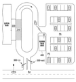
自走駐車制御部142は、例えば、通信装置20によって駐車場管理装置400から取得された情報に基づいて、自車両Mを駐車スペース内に駐車させる。図3は、第1の実施形態に係る自走駐車イベントが実行される場面を模式的に示す図である。道路Rdから訪問先施設に至るまでの経路には、ゲート300-inおよび300-outが設けられている。自車両Mは、手動運転または自動運転によって、ゲート300-inを通過して停止エリア310まで進行する。停止エリア310は、例えば、周辺認識部132により仮想的に設定される領域であり、訪問先施設に接続されている車寄せエリア320の両端から進路幅方向に延出した領域である。なお、車寄せエリア320に面して停止線や区画線などが設けられており停車推奨位置が設定されていると認識される場合、周辺認識部132は、停車推奨位置を停止エリア310とみなす。
[Self-propelled parking event-at the time of warehousing]
The self-propelled
自車両Mは、停止エリア310で乗員を下した後、無人で自動運転を行い、駐車エリアPA内の駐車スペースPSまで移動する自走駐車イベントを開始する。自走駐車イベントの開始トリガは、例えば、乗員による何らかの操作であってもよいし、駐車場管理装置400から無線により所定の信号を受信したことであってもよい。自走駐車制御部142は、自走駐車イベントを開始する場合、通信装置20を制御して駐車リクエストを駐車場管理装置400に向けて発信する。そして、自車両Mは、停止エリア310から駐車エリアPAまで、駐車場管理装置400の誘導に従って、或いは自力でセンシングしながら移動する。
After the occupant is dropped off in the
図4は、駐車場管理装置400の構成の一例を示す図である。駐車場管理装置400は、例えば、通信部410と、制御部420と、記憶部430とを備える。記憶部430には、駐車場地図情報432、駐車スペース状態テーブル434などの情報が格納されている。
FIG. 4 is a diagram showing an example of the configuration of the parking
通信部410は、自車両Mその他の車両と無線により通信する。制御部420は、通信部410により取得された情報と、記憶部430に格納された情報とに基づいて、車両を駐車スペースPSに誘導する。駐車場地図情報432は、駐車エリアPAの構造を幾何的に表した情報である。また、駐車場地図情報432は、駐車スペースPSごとの座標を含む。駐車スペース状態テーブル434は、例えば、駐車スペースPSの識別情報である駐車スペースIDに対して、空き状態であるか、満車(駐車中)状態であるかを示す状態と、満車状態である場合の駐車中の車両の識別情報である車両IDとが対応付けられたものである。
The
制御部420は、通信部410が車両から駐車リクエストを受信すると、駐車スペース状態テーブル434を参照して状態が空き状態である駐車スペースPSを抽出し、抽出した駐車スペースPSの位置を駐車場地図情報432から取得し、取得した駐車スペースPSの位置までの好適な経路を、通信部410を用いて車両に送信する。また、制御部420は、複数の車両の位置関係に基づいて、同時に同じ位置に車両が進行しないように、必要に応じて特定の車両に停止・徐行などを指示する。
When the
経路を受信した車両(以下、自車両Mであるものとする)では、自走駐車制御部142が、経路に基づく目標軌道を生成する。また、目標となる駐車スペースPSが近づくと、駐車スペース認識部134が、駐車スペースPSを区画する駐車枠線などを認識し、駐車スペースPSの詳細な位置を認識して自走駐車制御部142に提供する。自走駐車制御部142は、これを受けて目標軌道を補正し、自車両Mを駐車スペースPSに駐車させる。
In the vehicle that has received the route (hereinafter referred to as the own vehicle M), the self-propelled
[自走駐車イベント-出庫時]
自走駐車制御部142および通信装置20は、自車両Mが駐車中も動作状態を維持している。自走駐車制御部142は、例えば、通信装置20が乗員の端末装置から駐車エリアPAから移動して停止エリア310で乗員を乗車させることを要求する迎車リクエストを受信した場合、自車両Mのシステムを起動させ、自車両Mを停止エリア310まで移動させる。迎車リクエストは、今すぐ自車両Mを出庫させて停止エリア310に移動を開始することの要求であってもよいし、停止エリア310への移動を開始する出庫予定時間を指定する要求であってもよいし、停止エリア310への到着予定時間(到着を希望する時間)を指定する要求であってもよい。この際に、自走駐車制御部142は、通信装置20を制御して駐車場管理装置400に、迎車リクエストに含まれる出庫予定時間または停止エリア310への到着予定時間(到着を希望する時間)に関する情報を含めて発進リクエストを送信する。駐車場管理装置400の制御部420は、入庫時と同様に、複数の車両の位置関係に基づいて、同時に同じ位置に車両が進行しないように、必要に応じて特定の車両に停止・徐行などを指示する。なお、駐車場管理装置400は、複数の車両の停止エリア310への到着を希望する時間が重複する場合に、迎車リクエストの受信順に応じて、または各々の乗員と調停して到着予定時間を調整する。停止エリア310まで自車両Mを移動させて乗員を乗せると自走駐車制御部142は動作を停止し、以降は手動運転、或いは別の機能部による自動運転が開始される。なお、自走駐車制御部142は、自車両Mが停止エリア310への移動を開始する際や、停止エリア310に到着した際に、乗員の端末装置に対して自車両Mの状態や位置に関する情報を通知するように通信装置20を制御してもよい。
[Self-propelled parking event-at the time of departure]
The self-propelled
なお、上記の説明に限らず、自走駐車制御部142は、通信に依らず、カメラ10、レーダ装置12、ファインダ14、または物体認識装置16による検出結果に基づいて空き状態の駐車スペースを自ら発見し、発見した駐車スペース内に自車両Mを駐車させてもよい。出庫時に関しても同様に、通信に依らず、自ら停止エリア310まで自車両Mを移動させてもよい。
Not limited to the above explanation, the self-propelled
周辺認識部132は、例えば、停止エリア310に進行する際に、周辺状況として、自車両Mと同様に停止エリア310に進行する他車両が存在するかを認識する。周辺認識部132は、例えば、停止エリア310に進行する他車両を認識した場合、更に、他車両が停止エリア310の手前に車列を成して待機していることを認識する。
For example, when traveling to the
車列の並び順は、各車両の車列への到着順であってもよいし、駐車場管理装置400等の外部装置により各車両の出庫予定時刻または出庫予定順が管理されるものであってもよい。また、車列は物理的に構成されるものであってもよいし、論理的に構成されるもの(例えば、駐車場管理装置400に各車両が停止エリア310に進行することを申請し、駐車場管理装置400により許可された車両から順番に、駐車エリアPAから停止エリア310への進行するものであり、各車両は許可されるまで駐車エリアPA内で待機する)であってもよい。以下の説明においては、車列が物理的に構成されるものとして説明する。
The order of the convoys may be the order of arrival of each vehicle in the convoy, or the scheduled delivery time or the scheduled delivery order of each vehicle is managed by an external device such as the parking
[停止エリアへの移動]
自走駐車制御部142は、通信装置20により迎車リクエストが受信された場合、駐車場管理装置400の誘導に従い、自車両Mを駐車エリアPAから停止エリア310まで移動させる。自走駐車制御部142は、周辺認識部132により停止エリア310に移動する他車両が認識された場合には、その他車両の挙動に応じて自車両Mを停止エリア310に移動させる。また、自走駐車制御部142は、例えば、他車両を追い抜かないように、且つ他車両に追い抜かれないように、自車両Mを走行させる。
[Move to stop area]
When the self-propelled
また、自走駐車制御部142は、例えば、他車両が停止エリア310に移動する順に車列を成して待機することが周辺認識部132により認識された場合には、その車列に自車両を並ばせて、自車両Mが停止エリア310に移動してもよい順番が来るまで待機する。
Further, for example, when the
[停止エリアでの待機制御]
自走駐車制御部142は、停止エリア310で自車両Mの乗員の乗降が完了し、乗員により出庫可能であることを示す操作が行われた場合には動作を停止する。それ以降は、手動運転、或いは別の機能部による自動運転が開始される。自走駐車制御部142は、停止エリア310で自車両Mの乗員の乗降が完了しなかった場合には、停止エリア310において周辺認識部132により認識された周辺状況に基づいて、停止エリア310からの退出条件を変更する。
[Standby control in stop area]
The self-propelled
図5~図7は、自走駐車制御部142による自走処理の一例を説明するための図である。自走駐車制御部142は、停止エリア310に自車両Mを移動させると、停止エリア310において自車両Mを乗員の乗降のために停止または徐行させ、その状態で自車両Mを待機させる。また、自走駐車制御部142は、停止エリア310に空きスペースがない場合には、停止線STまたは停止エリア310に移動するために待機する他車両の位置を認識して、自車両Mを好適な位置に停止または徐行させながら、空きスペースができるまで待機する。
5 to 7 are diagrams for explaining an example of self-propelled processing by the self-propelled
自走駐車制御部142は、図5に示すように、他車両mA1およびmA2が停止エリア310の内側に停車し、他車両mA3およびmA4が停止エリア310に移動するための車列を構成することが周辺認識部132により認識された場合、自車両Mを車列の最後尾に移動させて追従させる。すなわち、自走駐車制御部142は、他車両mA4と一定の車間距離を保ちつつ、他車両mA4と進行方向に対して横方向の位置を合わせた位置に自車両Mを移動させる。自走駐車制御部142は、自車両Mの直前を走行する前走車両である他車両mA4を一定の車間距離を保ちつつ追従することで、自車両Mを停止エリア310へ移動させてもよい順番が来るのを待つ。
As shown in FIG. 5, the self-propelled
図6は、図5に示す状態において停止エリア310の内側に停車していた他車両mA1およびmA2が停止エリア310を退出し、さらに車列を構成していた他車両mA3およびmA4が停止エリア310の内側に停車する様子を示すものである。自走駐車制御部142は、図6に示すように車列を構成する前走車両である他車両mA4が停止エリア310の内側に移動したことにより、自車両Mが車列の先頭になる場合、前走車両を追従する制御を終了する。さらに自走駐車制御部142は、例えば、周辺認識部132により停止エリア310の空きスペースが認識されるまで、周辺認識部132により認識される停止線STに基づいて自車両Mを停車させる位置を決定して、その位置で自車両Mを待機させる。
In FIG. 6, the other vehicles mA1 and mA2 stopped inside the
自走駐車制御部142は、停止エリア310の空きスペースを認識すると、その空きスペースに自車両Mを移動させる。空きスペースとは、自車両Mの車長に対して駐車ができる程度の余裕分を加算した前後方向の空きがあるスペースである。
When the self-propelled
周辺認識部132は、例えば、前走車両である他車両mA4が停止エリア310を退出し、他車両mA4の停車位置付近に空きスペースができたことを認識する。自走駐車制御部142は、図7に示すように周辺認識部132により認識された停止エリア310の空きスペースに自車両Mを移動させ、空きスペースで停車させる。
The
自走駐車制御部142は、自車両Mが停止エリア310に停止している時間を待機時間として計測する。自走駐車制御部142は、例えば、自車両Mの全体が停止エリア310の内側に収まって自車両Mの速度が所定車速以下となった場合に、乗員の待機を開始したものとして、待機時間の計測を開始する。これに代えて、自走駐車制御部142は、例えば、自車両Mの一部が停止エリア310の内側に収まって自車両Mの速度が所定車速以下となった場合に、乗員の待機を開始したものとして、待機時間の計測を開始してもよい。なお、自走駐車制御部142は、乗員の利用する端末装置に停止エリア310で待機していることを、通信装置20を介して通知してもよい。
The self-propelled
自走駐車制御部142は、自車両Mが停止エリア310において待機を開始してから第1時間(例えば、数十[sec]程度の時間)が経過した場合に、自車両Mを停止エリア310から退出させる。なお、「待機」とは、例えば、自車両Mが停止エリア310に停車してから、乗員の乗降が開始されるまでの状態を指すものであって、自車両Mの乗員が自車両Mの停車位置を認識して自車両Mの方向に移動したり、自車両Mに荷物を載せたりする間の停車時間は「待機」には含まれない。
The self-propelled
自走駐車制御部142は、周辺認識部132により認識された周辺状況や、通信装置20により受信された予約状況に応じて第1時間を変更(補正)することで退出条件を変更する。第1時間を変更することは、停止エリア310からの退出条件を変更することの一例である。
The self-propelled
「第1時間を変更する」ことは、例えば、以下に示す(1)~(3)のような事象に基づいて行われる。
(1):周辺認識部132により認識された停止エリア310に移動するための車列の長さまたは台数。
(2):周辺認識部132により自車両Mの乗員とは異なる一定数以上の人物が認識され、それらの人物による自車両Mへの視線が検出されたこと。
(3):通信装置20により他車両が停止エリア310を使用する予約の有無および予約時間を含む予約状況を受信したこと。
"Changing the first time" is performed, for example, based on the following events (1) to (3).
(1): The length or the number of convoys for moving to the
(2): The
(3): The
[(1):車列に基づく第1時間の変更]
自走駐車制御部142は、停止エリア310に自車両Mを移動させる際に、同じく停止エリア310に移動する他車両が停止エリア310に移動する順に車列を成して待機していることが周辺認識部132により認識された場合、その車列の長さの認識結果に基づいて、退出条件を変更する。
[(1): Change of the first time based on the convoy]
When the self-propelled
車列の長さとは、例えば、カメラ10により撮像された画像に基づいて車列の先頭から最後尾までの長さである。また、周辺認識部132により車列の先頭車両は認識できないが、最後尾の車両が認識可能である場合(または周辺認識部132により車列の最後尾の車両は認識できないが、先頭の車両が認識可能である場合)、駐車場地図情報432を参照して車列の先頭(または停止エリア310)から車列の最後尾までの長さを導出してもよい。また、車列の長さは、車列を構成する車両の台数と、標準的な車両の全長と車間距離とを足した長さ(例えば、6[m]程度)とを乗算することで導出されてもよく、以下の説明において「車列の長さが所定の長さ以上」であることは「車列を構成する台数が所定の台数以上」であることに読み替えられてもよい。
The length of the convoy is, for example, the length from the beginning to the end of the convoy based on the image captured by the
自走駐車制御部142は、周辺認識部132により認識された車列の長さが所定の長さ以上である場合、第1時間を短くすることで、乗員が車寄せエリア320に到着しておらず乗車ができないような場合に、自車両Mが停止エリア310の一角を占拠して交通流を滞らせるといったことが起こらないようにする。
When the length of the vehicle line recognized by the
例えば、自走駐車制御部142は、周辺認識部132により自車両Mよりも後に停止エリア310に到着する他車両が停止エリア310の手前に車列を成して待機する場合、その車列の長さが所定の長さ以上であると認識された場合に、第1時間を15[sec]程度短くする。第1時間の変更量は、車列の長さに応じて可変であってもよく、車列の長さが長いほど第1時間をより短くするといった変更量の調整が行われてもよい。このようにすることで、車列で待機する後続車両に停止エリア310を譲り、車列が長くなることを抑制することができる。
For example, when the self-propelled
また、自走駐車制御部142は、周辺認識部132により車列がないことが認識された場合、自車両Mが停止エリア310を退出しなくても交通流を滞らせる可能性が低いため、第1時間を15[sec]程度長くしてもよい。
Further, when the self-propelled
[(2):視線検出時に基づく第1時間の変更]
自走駐車制御部142は、周辺認識部132により車寄せエリア320の内側に自車両Mの乗員以外の人物(例えば、他車両の乗員や、訪問先施設の警備担当者)が存在すると認識し、且つ、そのうち一定数以上の人物が自車両Mの方向を見る視線を検出した場合に、第1時間が経過していなくても自車両Mを停止エリア310から退出させる(すなわち、第1時間を短く変更する)。これは、その人物が自車両Mの停車時間が長いことを不審または不満に思って自車両Mを見ていると仮定したものである。乗員以外の人物の視線は、例えば、カメラ10により撮像された画像において認識された、その人物の顔の向きから推定する。なお、周辺認識部132は、自車両Mの乗員以外の人物の視線に加えて、その人物の自車両Mを指し示すジェスチャを検出してもよい。
[(2): Change of first time based on line-of-sight detection]
The self-propelled
[(3):予約時間に基づく第1時間の補正]
駐車場管理装置400が各車両に停止エリア310の利用を許可する時間の予約を受け付けるものである場合、自走駐車制御部142は、その予約時間と自車両Mが停止エリア310において滞留する時間との差分とに基づいて第1時間を補正するものであってもよい。例えば、通信装置20は、他車両が停止エリア310を使用する予約の有無および予約時間を含む予約状況を受信し、自走駐車制御部142に出力する。自走駐車制御部142は、通信装置20により受信された予約状況に基づいて自車両Mや車列で待機する後続車両の予約の有無および予約時間を認識し、その予約時間に基づいて第1時間を補正する。その場合、自走駐車制御部142は、例えば、自車両Mの予約時間が終了するタイミング(または、車列で待機する後続車両の予約時間が開始されるタイミング)が第1時間の終了よりも早い場合、予約時間が守られるよう第1時間を短く補正する。
[(3): Correction of the first time based on the reserved time]
When the parking
[停止エリア退出後の制御]
自走駐車制御部142は、例えば、自車両Mに乗員を乗車させることができずに停止エリア310を退出する場合、自車両Mを再度停止エリア310に移動する車列に並び直すように制御する。
[Control after leaving the stop area]
For example, when the self-propelled
図7に戻り、車列の最後尾が他車両mD3である場合、自走駐車制御部142は、例えば、自車両Mを停止エリア310から退出させて、さらに他車両mD3の後ろに並び直させる。このとき、自走駐車制御部142は、自車両Mが駐車エリアPAを出発してから車列に並んだ回数を1[回]加算する処理を行う。
Returning to FIG. 7, when the end of the vehicle line is the other vehicle mD3, the self-propelled
自走駐車制御部142は、例えば、自車両Mに乗員を乗車させることができずに停止エリア310を退出し、且つ乗員の利用する端末装置からの迎車リクエストを受信後に駐車エリアPAを出発してから車列に並んだ回数が所定回数(例えば、2~3[回]程度)未満である場合には、自車両Mを再度車列に並ばせて自車両Mに乗員を乗車させることができるかリトライしてもよい。
For example, the self-propelled
所定回数は、自車両Mの乗員によってあらかじめ設定されるものであってもよいし、周辺認識部132により認識された周辺状況に応じて可変であってもよいし、駐車場管理装置400により調整されてもよい。例えば、停止エリア310に移動する車列の長さが所定の長さ以上である場合には、駐車場内の混雑を緩和したり抑止したりするために、駐車場管理装置400により所定回数を平常時よりも少なくするといった調整がなされた場合、自走駐車制御部142はその調整を受け付ける(すなわち、平常時であれば3[回]まで車列に並んでリトライ可能だが、混雑時には1[回]のみリトライ可能とするといった調整を受け付ける)。また、自走駐車制御部142は、車列への並び直しによって消費された駆動源エネルギーの消費量や、並び直し時の移動距離に応じて所定回数を調整してもよい。
The predetermined number of times may be set in advance by the occupant of the own vehicle M, may be variable according to the surrounding conditions recognized by the
[外部装置への通知]
図8は、通信装置20と通信する乗員の端末装置により表示される表示画面の遷移例である。まず、乗員は自車両Mを出庫させる専用アプリケーションの迎車ボタンB1を押下すること等により迎車リクエストを送信する。図8の画面イメージIM1は、専用アプリケーションにより表示される画面の一例である。画面イメージIM1には、例えば、停止エリア310への自車両Mの到着予定時刻や、停止エリア310への移動中である車両台数等の駐車場管理装置400により提供される情報が表示されてもよい。また、画面イメージIM1において迎車ボタンB1の表示に加えて、出庫予定時間や、停止エリア310への到着予定時間(到着を希望する時間)の入力を受け付けてもよい。以下、専用アプリケーションによって自車両Mの位置情報が適宜乗員に通知されるものとして説明する。
[Notification to external device]
FIG. 8 is an example of a transition of the display screen displayed by the terminal device of the occupant communicating with the
自走駐車制御部142は、通信装置20を制御して迎車リクエストを駐車場管理装置400に向けて発信して、駐車エリアPAから停止エリア310までの移動を開始すると、図8の画面IMイメージ2に示すように、自車両Mがどのエリアに向かっており又は停止しているかを、通信装置20を介して乗員の利用する端末装置に通知させる。また、自走駐車制御部142は、自車両Mが停止する予定の停止エリア310に、区画を識別する番号や名称が設定されている場合には、図8の画面イメージIM3に示すように、その情報を乗員の端末装置に通知させてもよい。
When the self-propelled
自走駐車制御部142は、停止エリア310において待機しても乗員が現れなかったため自車両Mを車列に再度並ばせる場合に、図8の画面イメージIM4に示すような情報を乗員の端末装置に通知させる。また、自走駐車制御部142は、停止エリア310においての待機を所定回数行っても乗員が現れなかったため自車両Mを駐車エリアPAに移動させる場合に、図8の画面イメージIM5に示すような情報を乗員の端末装置に通知させる。なお、乗員の端末装置で機能する専用アプリケーションは、画面イメージIM2~IM4を表示するタイミングにおいて、自車両Mが停止エリア310に移動することをキャンセルして駐車エリアPAに戻させるという乗員の指示を受け付けるボタンB2等を表示して、その操作を受け付けてもよい。
When the self-propelled
自走駐車制御部142は、駐車エリアPAに戻ると図8の画面イメージIM6に示すような情報を乗員の端末装置に通知させる。このように、自走駐車制御部142は、自車両Mがどのエリアにいるのかを乗員に通知することで、乗員が自車両Mに乗車するタイミングを見計らいやすくすることができる。
When the self-propelled
[処理フロー]
図9および図10は、自動運転制御装置100による自車両Mの出庫処理の流れの一例を示すフローチャートである。
[Processing flow]
9 and 10 are flowcharts showing an example of the flow of the delivery process of the own vehicle M by the automatic
図9は、主として駐車エリアPAから自車両Mを移動させて出庫するまでの処理の流れの一例を示すフローチャートである。 FIG. 9 is a flowchart showing an example of a processing flow mainly from the parking area PA to moving the own vehicle M to leaving the garage.
まず、自走駐車制御部142は、乗員の端末装置より迎車リクエストを受信したか否かを判定する(ステップS100)。迎車リクエストを受信したと判定しなかった場合、自走駐車制御部142は、迎車リクエストを受信したと判定されるまで、周期的にステップS100の処理を繰り返す。迎車リクエストを受信したと判定した場合、自走駐車制御部142は、停止エリア310への移動を開始する(ステップS102)。
First, the self-propelled
次に、周辺認識部132は周辺状況を認識する(ステップS104)。次に、自走駐車制御部142は、周辺認識部132により車列があると認識されたか否かを判定する(ステップS106)。車列があると認識されなかった場合、自走駐車制御部142は、自車両Mを停止エリア310に移動させて、停止エリア310の内側で停車後に乗員の待機を開始する(ステップS108)。車列があると認識された場合、自走駐車制御部142は、自車両Mを車列に移動させ、停止エリア310へ移動するための順番待ちを行い(ステップS110)、自車両Mが車列の先頭になり、停止エリア310に空きスペースが発生したことが周辺認識部132により認識されたらステップS108に処理を進める。
Next, the
ステップS108の処理の後、自走駐車制御部142は、周辺認識部132の認識結果に基づいて乗員の乗降が開始されたか否かを判定する(ステップS112)。乗員の乗降が開始されたと判定された場合、自走駐車制御部142は、乗員の乗降が完了したか否かを判定する(ステップS114)。乗員の乗降が完了したと判定された場合、行動計画生成部140は、自車両Mを出庫させる制御を開始する(ステップS116)。
After the process of step S108, the self-propelled
図10は、自走駐車制御部142が乗員を乗車させるために自車両Mを移動させたり待機させたりする処理の流れの一例を示すフローチャートである。
FIG. 10 is a flowchart showing an example of a flow of processing in which the self-propelled
ステップS112の処理において乗員の乗降が開始されたと認定されなかった場合、自走駐車制御部142は、周辺認識部132により認識された停止エリア310の周辺状況に基づいて、停止エリア310の退出条件を変更し(ステップS118)、第1時間が経過したか否か、すなわち待機を継続するか否かを判定する(ステップS120)。待機を継続すると判定した場合、自走駐車制御部142は、処理をステップS112に戻す。待機を継続しないと判定した場合、自走駐車制御部142は、自車両Mを停止エリア310から退出させる(ステップS122)。
If it is not determined that the passengers have started getting on and off in the process of step S112, the self-propelled
次に、自走駐車制御部142は、待機回数が所定回数に到達したか否かを判定し(ステップS124)、待機回数が所定回数に到達していないと判定された場合、ステップS104に処理を戻す。待機回数が所定回数に到達したと判定された場合、自走駐車制御部142は、自車両Mを駐車エリアPAに移動させる(ステップS126)。以上、本フローチャートの処理の説明を終了する。
Next, the self-propelled
なお、ステップS102~S112、およびS118~S124の処理を実施中に、図8に示した自車両Mが停止エリア310に移動することをキャンセルして駐車エリアPAに戻させるという乗員の指示を受け付けるボタンB2が押下された場合には、実施中の処理を中断または省略してステップS126に処理を進める。
During the processing of steps S102 to S112 and S118 to S124, the occupant's instruction to cancel the movement of the own vehicle M shown in FIG. 8 to the
[処理フロー 第1時間の変更]
図11は、自走駐車制御部142による第1時間の変更処理の流れの一例を示すフローチャートである。図11に示すフローチャートは、図10のステップS118の処理に該当する。
[Change of processing flow 1st time]
FIG. 11 is a flowchart showing an example of the flow of the change processing of the first time by the self-propelled
まず、周辺認識部132は、周辺状況を認識する(ステップS200)。次に、自走駐車制御部142は、周辺認識部132により車列が認識されたか否かを判定する(ステップS202)。周辺認識部132により車列があると認識されなかった場合、自走駐車制御部142は、処理をステップS208に進める。周辺認識部132により車列があると認識された場合、自走駐車制御部142は、その車列の長さが所定の長さ以上か、またはその車列を構成する台数が所定の台数以上か否かを判定する(ステップS204)。車列の長さが所定の長さ以上、または車列を構成する台数が所定の台数以上であると判定した場合、自走駐車制御部142は、第1時間を短くする(ステップS206)。車列の長さが所定の長さ未満、且つ車列を構成する台数が所定の台数未満であると判定した場合、自走駐車制御部142は、ステップS208に処理を進める。
First, the
次に、自走駐車制御部142は、周辺認識部132により一定数以上の視線が検出されたか否かを判定する(ステップS208)。自走駐車制御部142は、一定数以上の視線が検出されたと判定されなかった場合、ステップS212に処理を進める。一定数以上の視線が検出されたと判定された場合、自走駐車制御部142は、第1時間を短くする(ステップS210)。
Next, the self-propelled
次に、自走駐車制御部142は、通信装置20を介して予約状況を受信する(ステップS212)。次に、自走駐車制御部142は、予約があるか(自車両Mの予約でもよいし、車列で待機する後続車両の予約でもよい)否かを判定する(ステップS214)。予約があると判定された場合、自走駐車制御部142は、その予約時間に応じて第1時間を補正する(ステップS216)。予約がないと判定された場合、自走駐車制御部142は、処理を終了する。以上、本フローチャートの処理の説明を終了する。
Next, the self-propelled
なお、図11に示したフローチャートのステップS202において車列がないと認識された場合、自走駐車制御部142は、第1時間を長くする処理を行ってもよい。
If it is recognized in step S202 of the flowchart shown in FIG. 11 that there is no vehicle line, the self-propelled
以上、第1の実施形態の自動運転制御装置100によれば、自車両Mの周辺状況を認識する周辺認識部132と、周辺認識部132の認識結果に基づいて、乗員の操作に依らずに自車両Mの操舵および速度を制御する行動計画生成部140および第2制御部160と、駐車場管理装置400等の外部装置と通信する通信装置20と、を備え、自走駐車制御部142は、通信装置20により、駐車エリアPAから移動して停止エリア310で乗員を乗車させることを要求する迎車リクエストが受信された場合、迎車リクエストに含まれる移動開始時間または停止エリア310への到着予定時間に応じて自車両Mを駐車エリアPAから停止エリア310まで移動させ、停止エリア310の付近において周辺認識部132により認識された停止エリア310に移動する他の車両等の周辺状況に基づいて、停止エリア310からの退出条件を変更することにより、乗員が車寄せエリア320に到着する時間が遅れた場合であっても停止エリア310から一度退出させて他車両に停止エリア310を譲ってから、再度停止エリア310に移動したり、他車両の交通流を滞らせないように停止エリア310または駐車エリアPAで待機したりすることで、より円滑に乗員を車両に乗車させることができる。
As described above, according to the automatic
<第2の実施形態>
第2の実施形態に係る車両システム1は、第1の実施形態に係る車両システム1と同様の構成により実現可能である。以下、第1の実施形態に係る車両システム1に含まれる構成と同じ名称および同じ符号を用いて、異なる点についてのみ説明する。
<Second embodiment>
The
図12は、第2の実施形態に係る自走駐車イベントが実行される場面を模式的に示す図である。図12に示す駐車場には、図3に示した訪問先施設に併設される駐車場において、さらに駐車場内の交通流を整える際などに車両を一時的に停止させる領域である、一時退避エリア330が設定されたものである。 FIG. 12 is a diagram schematically showing a scene in which the self-propelled parking event according to the second embodiment is executed. The parking lot shown in FIG. 12 is a temporary evacuation area in the parking lot attached to the visited facility shown in FIG. 3, which is an area for temporarily stopping the vehicle when the traffic flow in the parking lot is adjusted. 330 is set.
[一時退避エリア]
自走駐車制御部142は、例えば、自車両Mが乗員により迎車リクエストを受信してから停止エリア310への移動した後、自車両Mに乗員を乗車させることができずに停止エリア310を退出した場合、自車両Mを再度停止エリア310に移動させる前に一時退避エリア330に移動させることで、停止エリア310への到着予定時刻を調整する。また、自走駐車制御部142は、自車両Mに乗員を乗車させることができずに停止エリア310を退出し、且つ駐車エリアPAを出発してから車列に並んだ回数が所定回数に到達している場合、自車両Mを駐車エリアPAに戻させる前に一時退避エリア330に移動させるかを選択する。
[Temporary evacuation area]
For example, the self-propelled
自走駐車制御部142は、例えば、周辺認識部132により認識された周辺状況に基づいて、自車両Mを一時退避エリア330に移動させて待機させるか、駐車エリアPAに移動させるかを決定する。例えば、自走駐車制御部142は、一時退避エリア330に他車両が停車しているが、自車両Mが停車する程度の空きスペースがあると周辺認識部132により認識される場合には、一時退避エリア330に移動させると決定する。また、自走駐車制御部142は、自車両Mを一時退避エリア330に移動させる過程で一時退避エリア330が満車であることが周辺認識部132により認識される場合や、車列の長さが所定の長さ以上であると周辺認識部132により認識される場合には、自車両Mを駐車エリアPAに移動させると決定する。
The self-propelled
また、自走駐車制御部142は、通信装置20を介して駐車場管理装置400に自車両Mが一時退避エリア330に移動してもよいか、駐車エリアPAに移動した方がよいかの問い合わせを送信し、その問い合わせに対する応答を参照して移動先を決定してもよい。
Further, the self-propelled
自走駐車制御部142は、自車両Mを一時退避エリア330の内側に収めて停止させた場合に、停止エリア310での待機処理時と同様に、一時退避時間の計測を開始する。自走駐車制御部142は、一時退避してから第2時間(例えば、5~10[min]程度)経過した場合、自車両Mを停止エリア310に再度移動させて、自車両Mに乗員を乗車させることができるかリトライしてもよい。
When the self-propelled
第2時間は、周辺認識部132により認識される周辺状況に応じて可変であってもよく、例えば、一時退避エリア330に他車両が存在せず、且つ車列の長さが所定の長さ未満であると認識される場合には、駐車場内の混雑度合が低いものと解釈して、第2時間を長めに設定する(例えば、10~15[min]程度)と決定する。また、自走駐車制御部142は、周辺認識部132により一時退避エリア330が満車であることが認識され、且つ、自車両Mが一時退避エリア330での一時退避時間が他車両よりも長い場合には、第2時間を短くしたり、第2時間が経過していなくても自車両Mを駐車エリアPAに移動させたりしてもよい。
The second time may be variable depending on the surrounding conditions recognized by the
自走駐車制御部142は、例えば、一時退避エリア330での一時退避を開始したタイミングや、一時退避エリア330から退出するタイミングで通信装置20を介して乗員の端末装置に自車両Mの位置を通知する。また、自走駐車制御部142は、乗員の利用する端末装置からの迎車リクエストを再度受信した場合には、一時退避エリア330から自車両Mを退出させて、再度停止エリア310に移動させる(車列がある場合には、その車列に並ばせる)。
The self-propelled
なお、自走駐車制御部142は、一時退避エリア330から退出して停止エリア310へ移動する際に、車列に並んだ回数をリセットしてもよいし、リセットしなくてもよい。例えば、一時退避エリア330から退出して停止エリア310へ移動する際に、周辺認識部132により停止エリア310へ移動する車列が認識されなかった場合や車列の長さが所定の長さ未満であると認識された場合には、駐車場内がさほど混雑していないため、乗員を乗車させることができずに再度停止エリア310から退出することになったとしても、再び停止エリア310に移動する車列に並んでもよいといえる。したがって、自走駐車制御部142は、そのような場合には一時退避エリア330から退出する際に車列に並んだ回数をリセットする。
The self-propelled
[外部装置への通知]
図13は、第2の実施形態に係る通信装置20と通信する乗員の端末装置により表示される表示画面の遷移例である。図13に示す画面イメージIM1~IM4は、図8に示した画面イメージIM1~IM4と同様である。従って、下記では画面イメージIM5~IM7について説明する。
[Notification to external device]
FIG. 13 is an example of a transition of the display screen displayed by the terminal device of the occupant communicating with the
自走駐車制御部142は、停止エリア310においての待機を所定回数行っても乗員が現れなかったため自車両Mを一時退避エリア330に移動させる場合に、図8の画面イメージIM5に示すような情報を乗員の端末装置に通知させる。
When the self-propelled
自走駐車制御部142は、一時退避エリア330での一時退避を開始すると図8の画面イメージIM6に示すような情報を乗員の端末装置に通知させる。また、自走駐車制御部142は、一時退避エリア330での一時退避を開始してから第2時間が経過して駐車エリアPAに自車両Mを戻させる際に、図8の画面イメージIM7に示すような情報を乗員の端末装置に通知させる。
When the self-propelled
なお、乗員の端末装置で機能する専用アプリケーションは、画面イメージIM5~IM7を表示するタイミングにおいて、自車両Mに再度迎車リクエストを送信する迎車ボタンB1を表示して、その操作を受け付けてもよい。また、乗員の端末装置で機能する専用アプリケーションは、画面イメージIM2~IM4を表示するタイミングにおいて、自車両Mが車列に再度並ぶことをキャンセルして駐車エリアPAに戻させるという乗員の指示を受け付けるボタン等を表示して、その操作を受け付けてもよい。 The dedicated application functioning on the terminal device of the occupant may display the pick-up button B1 for transmitting the pick-up request again to the own vehicle M at the timing of displaying the screen images IM5 to IM7, and accept the operation. In addition, the dedicated application that functions on the occupant's terminal device accepts the occupant's instruction to cancel the re-arrangement of the own vehicle M in the convoy and return it to the parking area PA at the timing of displaying the screen images IM2 to IM4. A button or the like may be displayed to accept the operation.
[処理フロー]
図14は、第2の実施形態に係る自動運転制御装置100による自車両Mの出庫処理の流れの一例を示すフローチャートである。図14に示すフローチャートは、第1の実施形態における図10に対応するものであり、図9に示すフローチャートの処理のステップS112において乗員の乗降が開始されたと判定されなかった場合に行われる処理である。なお、図10のステップS118~S124は、図14のステップS318~S324に対応する。また、図10のステップS126は、図14のステップS340に対応する。従って、以下ではステップS326~S338を中心に説明する。
[Processing flow]
FIG. 14 is a flowchart showing an example of the flow of the delivery process of the own vehicle M by the automatic
ステップS324において、待機回数が所定回数に到達したと判定された場合、周辺認識部132は、一時退避エリア330が満車か否かを認識する(ステップS326)。自走駐車制御部142は、周辺認識部132により一時退避エリア330が満車であると認識された場合、ステップS336に処理を進める。自走駐車制御部142は、周辺認識部132により一時退避エリア330が満車でないと認識された場合、一時退避エリア330に自車両Mを移動させ(ステップS328)、周辺認識部132に一時退避エリア330の周辺状況を認識させて、一時退避条件を変更する(ステップS330)。
When it is determined in step S324 that the number of times of waiting has reached a predetermined number of times, the
次に、自走駐車制御部142は、乗員から停止エリア310に移動するよう迎車リクエストを受信したか否かを判定し(ステップS332)、迎車リクエストを受信したと判定された場合には図8のステップS104に処理を戻す。停止エリア310に移動するよう迎車リクエストを受信していないと判定された場合、自走駐車制御部142は、第2時間が経過したか否かを判定する(ステップS334)。第2時間が経過したと判定されなかった場合、自走駐車制御部142は、ステップS330に処理を戻す。第2時間が経過したと判定された場合、周辺認識部132は周辺状況を認識する(ステップS336)。次に自走駐車制御部142は、ステップS336における周辺認識部132による認識結果に基づいて、自車両Mを再度停止エリア310に移動させて、乗員を乗降させることをリトライするか否かを判定する(ステップS338)。リトライすると判定された場合、自走駐車制御部142は図8のステップS104に処理を戻す。リトライすると判定されなかった場合、自走駐車制御部142は、自車両Mを一時退避エリア330から退出させて、駐車エリアPAに移動させる(ステップS340)。以上、本フローチャートの処理の説明を終了する。
Next, the self-propelled
[処理フロー 第2時間の変更]
図15は、第2の実施形態に係る自走駐車制御部142による第2時間の変更処理の流れの一例を示すフローチャートである。図15に示すフローチャートは、図14のステップS330の処理に該当する。
[Change of processing flow 2nd time]
FIG. 15 is a flowchart showing an example of the flow of the change processing for the second time by the self-propelled
まず、周辺認識部132は、周辺状況を認識する(ステップS400)。次に、自走駐車制御部142は、周辺認識部132により車列が認識されたか否かを判定する(ステップS402)。周辺認識部132により車列があると認識されなかった場合、自走駐車制御部142は、処理をステップS308に進める。周辺認識部132により車列があると認識された場合、自走駐車制御部142は、その車列の長さが所定の長さ以上か、またはその車列を構成する台数が所定の台数以上か否かを判定する(ステップS404)。車列の長さが所定の長さ以上、または車列を構成する台数が所定の台数以上であると判定した場合、自走駐車制御部142は、第2時間を短くする(ステップS406)。車列の長さが所定の長さ未満、且つ車列を構成する台数が所定の台数未満であると判定した場合、自走駐車制御部142は、ステップS408に処理を進める。
First, the
次に、周辺認識部132は一時退避エリア330に空きスペースがあるか否かを判定する(ステップS408)。自走駐車制御部142は、周辺認識部132により空きスペースがあると判定された場合、処理を終了する。周辺認識部132により空きスペースがなく、満車状態であると判定された場合、自車両Mが一時退避エリア330に停車する車両の中で一時退避時間が一番長いか否かを判定する(ステップS410)。一番長いと判定した場合、自走駐車制御部142は、第2時間を短くする(ステップS412)。一番長いと判定しなかった場合、本フローチャートの処理を終了する。
Next, the
以上説明した第2の実施形態の自動運転制御装置100によれば、第1の実施形態と同様の効果を奏する他、自車両を停止エリア310から退出させた後、駐車エリアPAではなく一時退避エリア330に移動させて待機させることにより、より柔軟な待機態様を実現することができ、より円滑に乗員を車両に乗車させることができる。
According to the automatic
[ハードウェア構成]
図16は、実施形態の自動運転制御装置100のハードウェア構成の一例を示す図である。図示するように、自動運転制御装置100は、通信コントローラ100-1、CPU100-2、ワーキングメモリとして使用されるRAM(Random Access Memory)100-3、ブートプログラムなどを格納するROM(Read Only Memory)100-4、フラッシュメモリやHDDなどの記憶装置100-5、ドライブ装置100-6などが、内部バスあるいは専用通信線によって相互に接続された構成となっている。通信コントローラ100-1は、自動運転制御装置100以外の構成要素との通信を行う。記憶装置100-5には、CPU100-2が実行するプログラム100-5aが格納されている。このプログラムは、DMA(Direct Memory Access)コントローラ(不図示)などによってRAM100-3に展開されて、CPU100-2によって実行される。これによって、第1制御部120および第2制御部160のうち一部または全部が実現される。
[Hardware configuration]
FIG. 16 is a diagram showing an example of the hardware configuration of the automatic
上記説明した実施形態は、以下のように表現することができる。
プログラムを記憶した記憶装置と、
ハードウェアプロセッサと、を備え、
前記ハードウェアプロセッサが前記記憶装置に記憶されたプログラムを実行することにより、
車両の周辺状況を認識し、
前記周辺状況の認識結果に基づいて前記車両の操舵および速度を制御し、
乗員の利用する通信端末により送信された前記車両に前記乗員を乗車させて駐車場から出庫することの迎車リクエストを受信し、
前記迎車リクエストが受信された場合、前記車両を駐車エリアから停止エリアまで移動させ、前記停止エリアにおいて認識された前記周辺状況に基づいて前記停止エリアからの退出条件を変更する、
ように構成されている、車両制御装置。
The embodiment described above can be expressed as follows.
A storage device that stores the program and
With a hardware processor,
By executing the program stored in the storage device by the hardware processor.
Recognize the surrounding situation of the vehicle,
The steering and speed of the vehicle are controlled based on the recognition result of the surrounding situation.
Upon receiving a pick-up request to get the occupant on the vehicle and leave the parking lot, which is transmitted by the communication terminal used by the occupant,
When the pick-up request is received, the vehicle is moved from the parking area to the stop area, and the exit condition from the stop area is changed based on the peripheral situation recognized in the stop area.
Vehicle control unit configured as such.
以上、本発明を実施するための形態について実施形態を用いて説明したが、本発明はこうした実施形態に何等限定されるものではなく、本発明の要旨を逸脱しない範囲内において種々の変形及び置換を加えることができる。 Although the embodiments for carrying out the present invention have been described above using the embodiments, the present invention is not limited to these embodiments, and various modifications and substitutions are made without departing from the gist of the present invention. Can be added.
例えば、上述した第1時間は、乗員に応じて可変であってもよく、自走駐車制御部142は、乗員に年配者や幼児、車椅子等を使用する乗員等が含まれる場合には車寄せエリア320内での移動時間が長くなる可能性を考慮して第1時間が長めに設定されるようにしたり、第1時間を短くする処理が省略されるようにしたりしてもよい。
For example, the above-mentioned first hour may be variable depending on the occupant, and the self-propelled
また、例えば、周辺認識部132が停止エリア310において車列の長さを認識することができなかった場合、自走駐車制御部142は、自車両Mが駐車エリアPA、停止エリア310、一時退避エリア330などから退出して停止エリア310に到着するまでに要した時間に基づいて第1時間を設定してもよい。自走駐車制御部142は、停止エリア310に到着するまでに要した時間が前回停止エリア310に到着するまでに要した時間よりも長くなった場合には、停止エリア310に移動する車両が他にも多く存在しており混雑している(長い車列ができている)と仮定して、第1時間を短くする処理を行う。また、自走駐車制御部142は、停止エリア310に到着するまでに要した時間が長いか否かの判定基準として、駐車場管理装置400等により設定された標準時間や、車寄せエリア320周辺で車両を待つ人々の混雑度合を用いてもよい。
Further, for example, when the
100…自動運転制御装置、120…第1制御部、130…認識部、132…周辺認識部、134…駐車スペース認識部、140…行動計画生成部、142…自走駐車制御部、160…第2制御部、200…走行駆動力出力装置、210…ブレーキ装置、220…ステアリング装置、400…駐車場管理装置 100 ... Automatic driving control device, 120 ... First control unit, 130 ... Recognition unit, 132 ... Peripheral recognition unit, 134 ... Parking space recognition unit, 140 ... Action plan generation unit, 142 ... Self-propelled parking control unit, 160 ... No. 2 Control unit, 200 ... Driving drive force output device, 210 ... Brake device, 220 ... Steering device, 400 ... Parking lot management device
Claims (10)
前記認識部の認識結果に基づいて、乗員の操作に依らずに前記車両の操舵および速度を制御する運転制御部と、
外部装置と通信する通信部と、を備え、
前記運転制御部は、前記通信部により、駐車エリアから移動して停止エリアで前記乗員を乗車させることを要求する迎車リクエストが受信された場合、前記車両を前記駐車エリアから前記停止エリアまで移動させ、前記停止エリアに到着してから第1時間が経過した場合に、前記車両を前記停止エリアから退出させ、前記認識部により認識された前記周辺状況に基づく演算処理を行った結果に基づいて前記第1時間を変更し、
前記認識部は、前記車両よりも後に前記停止エリアに到着する他車両が前記停止エリアの手前に車列を成して待機する場合、前記車列の長さまたは台数を認識し、
前記運転制御部は、前記車列の長さまたは台数に基づいて前記第1時間を変更する、
車両制御装置。 A recognition unit that recognizes the surrounding conditions of the vehicle and
Based on the recognition result of the recognition unit, the operation control unit that controls the steering and speed of the vehicle without depending on the operation of the occupant,
Equipped with a communication unit that communicates with external devices,
The operation control unit moves the vehicle from the parking area to the stop area when the communication unit receives a pick-up request requesting that the occupant move from the parking area and get on the occupant in the stop area. When the first time has elapsed after arriving at the stop area, the vehicle is withdrawn from the stop area, and the calculation process based on the peripheral situation recognized by the recognition unit is performed. Change the first hour,
The recognition unit recognizes the length or the number of vehicles in a convoy when other vehicles arriving in the stop area after the vehicle stand by in a convoy in front of the stop area.
The operation control unit changes the first time based on the length or the number of convoys.
Vehicle control device.
請求項1に記載の車両制御装置。 The operation control unit causes the vehicle to leave the stop area after the first time has passed since it arrived at the stop area, and then moves the vehicle to a temporary evacuation area different from the parking area to stand by.
The vehicle control device according to claim 1 .
請求項2に記載の車両制御装置。 When the second time has elapsed since the vehicle was moved to the temporary evacuation area and made to stand by, the operation control unit moves the vehicle to the stop area based on the peripheral situation recognized by the recognition unit. It is determined whether or not to retry the movement, and if it is determined not to retry, the vehicle is moved to the parking area again.
The vehicle control device according to claim 2 .
請求項2または3に記載の車両制御装置。 After receiving the pick-up request, the driving control unit parks the vehicle when the number of times the vehicle is lined up in a convoy or the number of times the vehicle has waited for the occupant to board in the stop area reaches a predetermined number of times. Move to the area,
The vehicle control device according to claim 2 or 3 .
請求項2から4のうちいずれか1項に記載の車両制御装置。 When the recognition unit recognizes that the temporary evacuation area is full in the process of moving the vehicle to the temporary evacuation area, the operation control unit moves the vehicle to the parking area instead of the temporary evacuation area. Move to
The vehicle control device according to any one of claims 2 to 4 .
前記運転制御部は、前記予約時間の終了時刻が前記停止エリアにおける滞留時間の終了時刻よりも早い場合、前記予約時間の終了時刻と前記滞留時間の終了時刻との差分に相当する時間、前記第1時間を短くする、
請求項1から5のうちいずれか1項に記載の車両制御装置。 The communication unit receives the reservation status including the presence / absence of a reservation for another vehicle to use the stop area and the reservation time.
When the end time of the reserved time is earlier than the end time of the dwell time in the stop area, the operation control unit has a time corresponding to the difference between the end time of the reserved time and the end time of the dwell time. Shorten one hour ,
The vehicle control device according to any one of claims 1 to 5 .
請求項1から6のうちいずれか1項に記載の車両制御装置。 The communication unit notifies the external device of which area the vehicle is heading for or is stopped.
The vehicle control device according to any one of claims 1 to 6 .
請求項1から7のうちいずれか1項に記載の車両制御装置。 When the vehicle waits for the occupant in the stop area and the recognition unit detects a line of sight to the own vehicle by a certain number of people different from the occupant, the driving control unit spends the first time. Shorten ,
The vehicle control device according to any one of claims 1 to 7 .
車両の周辺状況を認識し、
前記周辺状況の認識結果に基づいて前記車両の操舵および速度を制御し、
乗員の利用する通信端末により送信された前記車両に前記乗員を乗車させて駐車場から出庫することの迎車リクエストを受信し、
前記迎車リクエストが受信された場合、前記車両を駐車エリアから停止エリアまで移動させ、前記停止エリアに到着してから第1時間が経過した場合に、前記車両を前記停止エリアから退出させ、前記認識された前記周辺状況に基づく演算処理を行った結果に基づいて前記第1時間を変更し、
前記車両よりも後に前記停止エリアに到着する他車両が前記停止エリアの手前に車列を成して待機する場合、前記車列の長さまたは台数を認識し、
前記車列の長さまたは台数に基づいて前記第1時間を変更する、
車両制御方法。 The computer
Recognize the surrounding situation of the vehicle,
The steering and speed of the vehicle are controlled based on the recognition result of the surrounding situation.
Upon receiving a pick-up request to get the occupant on the vehicle and leave the parking lot, which is transmitted by the communication terminal used by the occupant,
When the pick-up request is received, the vehicle is moved from the parking area to the stop area , and when the first time has elapsed after arriving at the stop area, the vehicle is withdrawn from the stop area and the recognition is made. The first time is changed based on the result of performing the arithmetic processing based on the peripheral situation.
When another vehicle arriving at the stop area after the vehicle waits in a convoy in front of the stop area, the length or number of the convoy is recognized.
Change the first hour based on the length or number of convoys,
Vehicle control method.
車両の周辺状況を認識させ、
前記周辺状況の認識結果に基づいて前記車両の操舵および速度を制御させ、
乗員の利用する通信端末により送信された前記車両に前記乗員を乗車させて駐車場から出庫することの迎車リクエストを受信させ、
前記迎車リクエストが受信された場合、前記車両を駐車エリアから停止エリアまで移動させ、前記停止エリアに到着してから第1時間が経過した場合に、前記車両を前記停止エリアから退出させることを行わせ、前記認識された前記周辺状況に基づく演算処理を行った結果に基づいて前記第1時間を変更させ、
前記車両よりも後に前記停止エリアに到着する他車両が前記停止エリアの手前に車列を成して待機する場合、前記車列の長さまたは台数を認識させ、
前記車列の長さまたは台数に基づいて前記第1時間を変更させる、
プログラム。 On the computer
Recognize the surrounding situation of the vehicle
The steering and speed of the vehicle are controlled based on the recognition result of the surrounding situation.
Receive a pick-up request for the occupant to get on the vehicle and leave the parking lot, which is transmitted by the communication terminal used by the occupant.
When the pick-up request is received, the vehicle is moved from the parking area to the stop area , and when the first hour has passed after arriving at the stop area, the vehicle is removed from the stop area. Then, the first time is changed based on the result of performing the arithmetic processing based on the recognized peripheral situation.
When another vehicle arriving at the stop area after the vehicle waits in a convoy in front of the stop area, the length or number of the convoy is recognized.
Change the first time based on the length or number of convoys,
program.
Priority Applications (3)
| Application Number | Priority Date | Filing Date | Title |
|---|---|---|---|
| JP2018242634A JP7032294B2 (en) | 2018-12-26 | 2018-12-26 | Vehicle control devices, vehicle control methods, and programs |
| CN201910957656.5A CN111369781B (en) | 2018-12-26 | 2019-10-09 | Vehicle control device, vehicle control method, and storage medium |
| US16/598,069 US11447131B2 (en) | 2018-12-26 | 2019-10-10 | Vehicle control device, vehicle control method, and recording medium |
Applications Claiming Priority (1)
| Application Number | Priority Date | Filing Date | Title |
|---|---|---|---|
| JP2018242634A JP7032294B2 (en) | 2018-12-26 | 2018-12-26 | Vehicle control devices, vehicle control methods, and programs |
Publications (2)
| Publication Number | Publication Date |
|---|---|
| JP2020106920A JP2020106920A (en) | 2020-07-09 |
| JP7032294B2 true JP7032294B2 (en) | 2022-03-08 |
Family
ID=71122566
Family Applications (1)
| Application Number | Title | Priority Date | Filing Date |
|---|---|---|---|
| JP2018242634A Active JP7032294B2 (en) | 2018-12-26 | 2018-12-26 | Vehicle control devices, vehicle control methods, and programs |
Country Status (3)
| Country | Link |
|---|---|
| US (1) | US11447131B2 (en) |
| JP (1) | JP7032294B2 (en) |
| CN (1) | CN111369781B (en) |
Families Citing this family (5)
| Publication number | Priority date | Publication date | Assignee | Title |
|---|---|---|---|---|
| JP7238850B2 (en) * | 2020-05-07 | 2023-03-14 | トヨタ自動車株式会社 | Automated driving system and automated driving method |
| JP7322834B2 (en) * | 2020-08-07 | 2023-08-08 | トヨタ自動車株式会社 | Information processing device, information processing method, and system |
| JP7355045B2 (en) | 2021-02-18 | 2023-10-03 | トヨタ自動車株式会社 | Automatic parking system, automatic parking system control method, and automatic driving vehicle |
| CN112874538B (en) * | 2021-03-03 | 2022-04-15 | 深圳安途智行科技有限公司 | Control method of unmanned vehicle, and computer device |
| CN114495478A (en) * | 2021-12-20 | 2022-05-13 | 岚图汽车科技有限公司 | Fleet control method, fleet control device, fleet control medium and electronic equipment |
Citations (2)
| Publication number | Priority date | Publication date | Assignee | Title |
|---|---|---|---|---|
| JP2017182176A (en) | 2016-03-28 | 2017-10-05 | パナソニックIpマネジメント株式会社 | Automatic travel control method and automatic travel control device |
| JP2018156641A (en) | 2017-03-17 | 2018-10-04 | パナソニックIpマネジメント株式会社 | Vehicle operation management system and vehicle operation management method |
Family Cites Families (14)
| Publication number | Priority date | Publication date | Assignee | Title |
|---|---|---|---|---|
| JP3208400B2 (en) * | 1998-04-28 | 2001-09-10 | 住友商事株式会社 | Parking lot waiting time information provision device |
| JP3780331B2 (en) * | 2001-05-17 | 2006-05-31 | 国土交通省国土技術政策総合研究所長 | Traffic information processing method and traffic information processing system |
| US9645968B2 (en) * | 2006-09-14 | 2017-05-09 | Crown Equipment Corporation | Multiple zone sensing for materials handling vehicles |
| CN103456161B (en) * | 2012-05-28 | 2015-08-26 | 上海飞田通信技术有限公司 | By increasing the system and method for information symmetrical Assisted Passenger decision-making chauffeur |
| CN103065462A (en) * | 2012-06-28 | 2013-04-24 | 盛乐信息技术(上海)有限公司 | System of vehicle internet of things and vehicle scheduling method |
| JP2015219811A (en) * | 2014-05-20 | 2015-12-07 | トヨタ自動車株式会社 | Vehicle control system |
| US9792575B2 (en) * | 2016-03-11 | 2017-10-17 | Route4Me, Inc. | Complex dynamic route sequencing for multi-vehicle fleets using traffic and real-world constraints |
| US10209708B2 (en) * | 2016-07-28 | 2019-02-19 | Lytx, Inc. | Determining driver engagement with autonomous vehicle |
| CN107665476A (en) * | 2016-07-28 | 2018-02-06 | 北京京东尚科信息技术有限公司 | A kind of method and apparatus that Entrucking Point is provided for passenger |
| CN106781608B (en) * | 2016-12-27 | 2020-01-21 | 深圳市盛世任我行科技有限公司 | Method and system for acquiring arrival information of vehicle nearest to waiting station |
| CN107682419B (en) * | 2017-09-20 | 2021-01-05 | 汉海信息技术(上海)有限公司 | Car pooling route providing method, client, server and car pooling system |
| CN108417081A (en) * | 2018-04-29 | 2018-08-17 | 武汉理工大学 | A kind of roadside temporary parking management optimization method |
| CN108932862B (en) * | 2018-07-27 | 2020-09-29 | 北京小马智行科技有限公司 | Automatic driving vehicle scheduling method and device |
| US20200130676A1 (en) * | 2018-10-25 | 2020-04-30 | Magna Electronics Inc. | Autonomous vehicle parking system |
-
2018
- 2018-12-26 JP JP2018242634A patent/JP7032294B2/en active Active
-
2019
- 2019-10-09 CN CN201910957656.5A patent/CN111369781B/en active Active
- 2019-10-10 US US16/598,069 patent/US11447131B2/en active Active
Patent Citations (2)
| Publication number | Priority date | Publication date | Assignee | Title |
|---|---|---|---|---|
| JP2017182176A (en) | 2016-03-28 | 2017-10-05 | パナソニックIpマネジメント株式会社 | Automatic travel control method and automatic travel control device |
| JP2018156641A (en) | 2017-03-17 | 2018-10-04 | パナソニックIpマネジメント株式会社 | Vehicle operation management system and vehicle operation management method |
Also Published As
| Publication number | Publication date |
|---|---|
| CN111369781B (en) | 2022-06-24 |
| CN111369781A (en) | 2020-07-03 |
| US11447131B2 (en) | 2022-09-20 |
| US20200207349A1 (en) | 2020-07-02 |
| JP2020106920A (en) | 2020-07-09 |
Similar Documents
| Publication | Publication Date | Title |
|---|---|---|
| CN111771234B (en) | Vehicle control system, vehicle control method, and storage medium | |
| JP7176974B2 (en) | Pick-up management device, pick-up control method, and program | |
| JP7032294B2 (en) | Vehicle control devices, vehicle control methods, and programs | |
| US20200311849A1 (en) | Parking lot management device, parking lot management method, and program | |
| JP7096783B2 (en) | Vehicle control devices, vehicle control methods, and programs | |
| JP7065765B2 (en) | Vehicle control systems, vehicle control methods, and programs | |
| CN111986505B (en) | Control device, boarding/alighting facility, control method, and storage medium | |
| JP7096192B2 (en) | Parking management devices, parking management device control methods, and programs | |
| US20200311623A1 (en) | Parking management apparatus, method for controlling parking management apparatus, and storage medium | |
| JPWO2019069347A1 (en) | Vehicle control device, vehicle control method, and program | |
| US20200311783A1 (en) | Parking lot management device, parking lot management method, and storage medium | |
| US20200311622A1 (en) | Management device, management method, and storage medium | |
| JP2019156133A (en) | Vehicle controller, vehicle control method and program | |
| CN111932927B (en) | Management device, management method, and storage medium | |
| CN111762174A (en) | Vehicle control device, vehicle control method, and storage medium | |
| US11513527B2 (en) | Vehicle control device, vehicle control method, and storage medium | |
| JP2019164729A (en) | Vehicle control system, vehicle control method, and program | |
| JP7075789B2 (en) | Vehicle control devices, vehicle control methods, and programs | |
| CN111619568A (en) | Vehicle control device, vehicle control method, and storage medium | |
| US20200311621A1 (en) | Management device, management method, and storage medium | |
| WO2019167251A1 (en) | Vehicle control device, vehicle control system, management apparatus, vehicle control method, and program | |
| JP2020186563A (en) | Control device, parking lot system, control method and program | |
| CN114684132A (en) | Vehicle control device, vehicle control method, and computer-readable storage medium | |
| CN112009478A (en) | Vehicle control system, vehicle control method, and storage medium |
Legal Events
| Date | Code | Title | Description |
|---|---|---|---|
| A621 | Written request for application examination |
Free format text: JAPANESE INTERMEDIATE CODE: A621 Effective date: 20201130 |
|
| A977 | Report on retrieval |
Free format text: JAPANESE INTERMEDIATE CODE: A971007 Effective date: 20211027 |
|
| A131 | Notification of reasons for refusal |
Free format text: JAPANESE INTERMEDIATE CODE: A131 Effective date: 20211102 |
|
| A521 | Request for written amendment filed |
Free format text: JAPANESE INTERMEDIATE CODE: A523 Effective date: 20211217 |
|
| TRDD | Decision of grant or rejection written | ||
| A01 | Written decision to grant a patent or to grant a registration (utility model) |
Free format text: JAPANESE INTERMEDIATE CODE: A01 Effective date: 20220215 |
|
| A61 | First payment of annual fees (during grant procedure) |
Free format text: JAPANESE INTERMEDIATE CODE: A61 Effective date: 20220224 |
|
| R150 | Certificate of patent or registration of utility model |
Ref document number: 7032294 Country of ref document: JP Free format text: JAPANESE INTERMEDIATE CODE: R150 |