JP7029578B1 - Stent - Google Patents
Stent Download PDFInfo
- Publication number
- JP7029578B1 JP7029578B1 JP2021571402A JP2021571402A JP7029578B1 JP 7029578 B1 JP7029578 B1 JP 7029578B1 JP 2021571402 A JP2021571402 A JP 2021571402A JP 2021571402 A JP2021571402 A JP 2021571402A JP 7029578 B1 JP7029578 B1 JP 7029578B1
- Authority
- JP
- Japan
- Prior art keywords
- stent
- leg
- length
- leg portion
- adjacent
- Prior art date
- Legal status (The legal status is an assumption and is not a legal conclusion. Google has not performed a legal analysis and makes no representation as to the accuracy of the status listed.)
- Active
Links
- 238000003780 insertion Methods 0.000 claims description 9
- 230000037431 insertion Effects 0.000 claims description 9
- 210000004027 cell Anatomy 0.000 description 50
- 230000000052 comparative effect Effects 0.000 description 39
- 239000003550 marker Substances 0.000 description 29
- 229940079593 drug Drugs 0.000 description 19
- 239000003814 drug Substances 0.000 description 19
- 239000000463 material Substances 0.000 description 18
- 238000011161 development Methods 0.000 description 13
- 230000018109 developmental process Effects 0.000 description 13
- 238000005452 bending Methods 0.000 description 12
- 210000000056 organ Anatomy 0.000 description 12
- 229910045601 alloy Inorganic materials 0.000 description 10
- 239000000956 alloy Substances 0.000 description 10
- 229920000642 polymer Polymers 0.000 description 9
- 238000010586 diagram Methods 0.000 description 8
- 238000000034 method Methods 0.000 description 8
- 230000004048 modification Effects 0.000 description 7
- 238000012986 modification Methods 0.000 description 7
- BQCADISMDOOEFD-UHFFFAOYSA-N Silver Chemical compound [Ag] BQCADISMDOOEFD-UHFFFAOYSA-N 0.000 description 5
- 210000004204 blood vessel Anatomy 0.000 description 5
- 229910052709 silver Inorganic materials 0.000 description 5
- 239000004332 silver Substances 0.000 description 5
- PXHVJJICTQNCMI-UHFFFAOYSA-N Nickel Chemical compound [Ni] PXHVJJICTQNCMI-UHFFFAOYSA-N 0.000 description 4
- 239000003795 chemical substances by application Substances 0.000 description 4
- BASFCYQUMIYNBI-UHFFFAOYSA-N platinum Chemical compound [Pt] BASFCYQUMIYNBI-UHFFFAOYSA-N 0.000 description 4
- 230000005855 radiation Effects 0.000 description 4
- FYYHWMGAXLPEAU-UHFFFAOYSA-N Magnesium Chemical compound [Mg] FYYHWMGAXLPEAU-UHFFFAOYSA-N 0.000 description 3
- 229920000954 Polyglycolide Polymers 0.000 description 3
- HZEWFHLRYVTOIW-UHFFFAOYSA-N [Ti].[Ni] Chemical compound [Ti].[Ni] HZEWFHLRYVTOIW-UHFFFAOYSA-N 0.000 description 3
- 239000003146 anticoagulant agent Substances 0.000 description 3
- 230000005540 biological transmission Effects 0.000 description 3
- 238000005219 brazing Methods 0.000 description 3
- 229960003850 dabigatran Drugs 0.000 description 3
- YBSJFWOBGCMAKL-UHFFFAOYSA-N dabigatran Chemical compound N=1C2=CC(C(=O)N(CCC(O)=O)C=3N=CC=CC=3)=CC=C2N(C)C=1CNC1=CC=C(C(N)=N)C=C1 YBSJFWOBGCMAKL-UHFFFAOYSA-N 0.000 description 3
- 230000000694 effects Effects 0.000 description 3
- 238000005304 joining Methods 0.000 description 3
- 239000007788 liquid Substances 0.000 description 3
- 229910052749 magnesium Inorganic materials 0.000 description 3
- 239000011777 magnesium Substances 0.000 description 3
- 229910001000 nickel titanium Inorganic materials 0.000 description 3
- 239000004633 polyglycolic acid Substances 0.000 description 3
- 238000012545 processing Methods 0.000 description 3
- 230000008719 thickening Effects 0.000 description 3
- 229910052719 titanium Inorganic materials 0.000 description 3
- 239000010936 titanium Substances 0.000 description 3
- 238000003466 welding Methods 0.000 description 3
- RYGMFSIKBFXOCR-UHFFFAOYSA-N Copper Chemical compound [Cu] RYGMFSIKBFXOCR-UHFFFAOYSA-N 0.000 description 2
- 229940121710 HMGCoA reductase inhibitor Drugs 0.000 description 2
- XEEYBQQBJWHFJM-UHFFFAOYSA-N Iron Chemical compound [Fe] XEEYBQQBJWHFJM-UHFFFAOYSA-N 0.000 description 2
- 208000031481 Pathologic Constriction Diseases 0.000 description 2
- 229920000331 Polyhydroxybutyrate Polymers 0.000 description 2
- RTAQQCXQSZGOHL-UHFFFAOYSA-N Titanium Chemical compound [Ti] RTAQQCXQSZGOHL-UHFFFAOYSA-N 0.000 description 2
- 239000013543 active substance Substances 0.000 description 2
- 229910052782 aluminium Inorganic materials 0.000 description 2
- 229960004676 antithrombotic agent Drugs 0.000 description 2
- 229920002988 biodegradable polymer Polymers 0.000 description 2
- 239000004621 biodegradable polymer Substances 0.000 description 2
- 229920006167 biodegradable resin Polymers 0.000 description 2
- 229910052791 calcium Inorganic materials 0.000 description 2
- 239000011575 calcium Substances 0.000 description 2
- 229910052802 copper Inorganic materials 0.000 description 2
- 239000010949 copper Substances 0.000 description 2
- PCHJSUWPFVWCPO-UHFFFAOYSA-N gold Chemical compound [Au] PCHJSUWPFVWCPO-UHFFFAOYSA-N 0.000 description 2
- 229910052737 gold Inorganic materials 0.000 description 2
- 239000010931 gold Substances 0.000 description 2
- 230000008595 infiltration Effects 0.000 description 2
- 238000001764 infiltration Methods 0.000 description 2
- 229910052759 nickel Inorganic materials 0.000 description 2
- 229910052758 niobium Inorganic materials 0.000 description 2
- 239000010955 niobium Substances 0.000 description 2
- 230000002093 peripheral effect Effects 0.000 description 2
- 229910052697 platinum Inorganic materials 0.000 description 2
- 239000005015 poly(hydroxybutyrate) Substances 0.000 description 2
- 239000004626 polylactic acid Substances 0.000 description 2
- 239000010935 stainless steel Substances 0.000 description 2
- 229910001220 stainless steel Inorganic materials 0.000 description 2
- 230000036262 stenosis Effects 0.000 description 2
- 208000037804 stenosis Diseases 0.000 description 2
- 229910052715 tantalum Inorganic materials 0.000 description 2
- 230000002792 vascular Effects 0.000 description 2
- XBBVURRQGJPTHH-UHFFFAOYSA-N 2-hydroxyacetic acid;2-hydroxypropanoic acid Chemical compound OCC(O)=O.CC(O)C(O)=O XBBVURRQGJPTHH-UHFFFAOYSA-N 0.000 description 1
- VSKXVGWORBZZDY-UHFFFAOYSA-N 2-hydroxypropanoic acid;oxepan-2-one Chemical compound CC(O)C(O)=O.O=C1CCCCCO1 VSKXVGWORBZZDY-UHFFFAOYSA-N 0.000 description 1
- WHBMMWSBFZVSSR-UHFFFAOYSA-N 3-hydroxybutyric acid Chemical compound CC(O)CC(O)=O WHBMMWSBFZVSSR-UHFFFAOYSA-N 0.000 description 1
- 239000005541 ACE inhibitor Substances 0.000 description 1
- 229910001316 Ag alloy Inorganic materials 0.000 description 1
- 229910018131 Al-Mn Inorganic materials 0.000 description 1
- 229910018461 Al—Mn Inorganic materials 0.000 description 1
- OYPRJOBELJOOCE-UHFFFAOYSA-N Calcium Chemical compound [Ca] OYPRJOBELJOOCE-UHFFFAOYSA-N 0.000 description 1
- 229940127291 Calcium channel antagonist Drugs 0.000 description 1
- OKTJSMMVPCPJKN-UHFFFAOYSA-N Carbon Chemical compound [C] OKTJSMMVPCPJKN-UHFFFAOYSA-N 0.000 description 1
- 229910000925 Cd alloy Inorganic materials 0.000 description 1
- VYZAMTAEIAYCRO-UHFFFAOYSA-N Chromium Chemical compound [Cr] VYZAMTAEIAYCRO-UHFFFAOYSA-N 0.000 description 1
- 229910000599 Cr alloy Inorganic materials 0.000 description 1
- 229910017566 Cu-Mn Inorganic materials 0.000 description 1
- 229910017871 Cu—Mn Inorganic materials 0.000 description 1
- 239000004129 EU approved improving agent Substances 0.000 description 1
- HKVAMNSJSFKALM-GKUWKFKPSA-N Everolimus Chemical compound C1C[C@@H](OCCO)[C@H](OC)C[C@@H]1C[C@@H](C)[C@H]1OC(=O)[C@@H]2CCCCN2C(=O)C(=O)[C@](O)(O2)[C@H](C)CC[C@H]2C[C@H](OC)/C(C)=C/C=C/C=C/[C@@H](C)C[C@@H](C)C(=O)[C@H](OC)[C@H](O)/C(C)=C/[C@@H](C)C(=O)C1 HKVAMNSJSFKALM-GKUWKFKPSA-N 0.000 description 1
- 244000043261 Hevea brasiliensis Species 0.000 description 1
- 102000014150 Interferons Human genes 0.000 description 1
- 108010050904 Interferons Proteins 0.000 description 1
- ZOKXTWBITQBERF-UHFFFAOYSA-N Molybdenum Chemical compound [Mo] ZOKXTWBITQBERF-UHFFFAOYSA-N 0.000 description 1
- 229910052779 Neodymium Inorganic materials 0.000 description 1
- HWBWPQJFPHMBHE-UHFFFAOYSA-N OCC(O)=O.O=C1OCCCO1 Chemical compound OCC(O)=O.O=C1OCCCO1 HWBWPQJFPHMBHE-UHFFFAOYSA-N 0.000 description 1
- 229930012538 Paclitaxel Natural products 0.000 description 1
- 239000004952 Polyamide Substances 0.000 description 1
- 239000004721 Polyphenylene oxide Substances 0.000 description 1
- 239000004734 Polyphenylene sulfide Substances 0.000 description 1
- QJJXYPPXXYFBGM-LFZNUXCKSA-N Tacrolimus Chemical compound C1C[C@@H](O)[C@H](OC)C[C@@H]1\C=C(/C)[C@@H]1[C@H](C)[C@@H](O)CC(=O)[C@H](CC=C)/C=C(C)/C[C@H](C)C[C@H](OC)[C@H]([C@H](C[C@H]2C)OC)O[C@@]2(O)C(=O)C(=O)N2CCCC[C@H]2C(=O)O1 QJJXYPPXXYFBGM-LFZNUXCKSA-N 0.000 description 1
- 208000007536 Thrombosis Diseases 0.000 description 1
- 229920006311 Urethane elastomer Polymers 0.000 description 1
- 229910000756 V alloy Inorganic materials 0.000 description 1
- 206010072810 Vascular wall hypertrophy Diseases 0.000 description 1
- 239000002253 acid Substances 0.000 description 1
- 229920000800 acrylic rubber Polymers 0.000 description 1
- XAGFODPZIPBFFR-UHFFFAOYSA-N aluminium Chemical compound [Al] XAGFODPZIPBFFR-UHFFFAOYSA-N 0.000 description 1
- 229940044094 angiotensin-converting-enzyme inhibitor Drugs 0.000 description 1
- 239000005557 antagonist Substances 0.000 description 1
- 239000003242 anti bacterial agent Substances 0.000 description 1
- 239000002260 anti-inflammatory agent Substances 0.000 description 1
- 229940121363 anti-inflammatory agent Drugs 0.000 description 1
- 239000000043 antiallergic agent Substances 0.000 description 1
- 229940088710 antibiotic agent Drugs 0.000 description 1
- 239000003472 antidiabetic agent Substances 0.000 description 1
- 239000002246 antineoplastic agent Substances 0.000 description 1
- 239000003963 antioxidant agent Substances 0.000 description 1
- 239000003435 antirheumatic agent Substances 0.000 description 1
- 229940127217 antithrombotic drug Drugs 0.000 description 1
- 229960003856 argatroban Drugs 0.000 description 1
- KXNPVXPOPUZYGB-XYVMCAHJSA-N argatroban Chemical compound OC(=O)[C@H]1C[C@H](C)CCN1C(=O)[C@H](CCCN=C(N)N)NS(=O)(=O)C1=CC=CC2=C1NC[C@H](C)C2 KXNPVXPOPUZYGB-XYVMCAHJSA-N 0.000 description 1
- 239000008280 blood Substances 0.000 description 1
- 210000004369 blood Anatomy 0.000 description 1
- 229910052799 carbon Inorganic materials 0.000 description 1
- 239000003575 carbonaceous material Substances 0.000 description 1
- 230000008859 change Effects 0.000 description 1
- 229910052804 chromium Inorganic materials 0.000 description 1
- 239000011651 chromium Substances 0.000 description 1
- 229910017052 cobalt Inorganic materials 0.000 description 1
- 239000010941 cobalt Substances 0.000 description 1
- GUTLYIVDDKVIGB-UHFFFAOYSA-N cobalt atom Chemical compound [Co] GUTLYIVDDKVIGB-UHFFFAOYSA-N 0.000 description 1
- 230000006835 compression Effects 0.000 description 1
- 238000007906 compression Methods 0.000 description 1
- 230000008602 contraction Effects 0.000 description 1
- 229920001577 copolymer Polymers 0.000 description 1
- 238000005520 cutting process Methods 0.000 description 1
- 230000000916 dilatatory effect Effects 0.000 description 1
- 239000013013 elastic material Substances 0.000 description 1
- 210000002889 endothelial cell Anatomy 0.000 description 1
- 239000005038 ethylene vinyl acetate Substances 0.000 description 1
- 229960005167 everolimus Drugs 0.000 description 1
- 230000001747 exhibiting effect Effects 0.000 description 1
- 239000003925 fat Substances 0.000 description 1
- 229930003935 flavonoid Natural products 0.000 description 1
- 150000002215 flavonoids Chemical class 0.000 description 1
- 235000017173 flavonoids Nutrition 0.000 description 1
- 229920005570 flexible polymer Polymers 0.000 description 1
- -1 fluororesin Polymers 0.000 description 1
- 230000006870 function Effects 0.000 description 1
- 230000009477 glass transition Effects 0.000 description 1
- 238000009499 grossing Methods 0.000 description 1
- 239000003966 growth inhibitor Substances 0.000 description 1
- 230000012447 hatching Effects 0.000 description 1
- 239000002471 hydroxymethylglutaryl coenzyme A reductase inhibitor Substances 0.000 description 1
- 229940126904 hypoglycaemic agent Drugs 0.000 description 1
- 229960003444 immunosuppressant agent Drugs 0.000 description 1
- 239000003018 immunosuppressive agent Substances 0.000 description 1
- 239000003112 inhibitor Substances 0.000 description 1
- 230000002401 inhibitory effect Effects 0.000 description 1
- 102000006495 integrins Human genes 0.000 description 1
- 108010044426 integrins Proteins 0.000 description 1
- 229940079322 interferon Drugs 0.000 description 1
- 210000000936 intestine Anatomy 0.000 description 1
- 229910052742 iron Inorganic materials 0.000 description 1
- 230000003902 lesion Effects 0.000 description 1
- 150000002632 lipids Chemical class 0.000 description 1
- 229910052744 lithium Inorganic materials 0.000 description 1
- 238000003754 machining Methods 0.000 description 1
- 230000014759 maintenance of location Effects 0.000 description 1
- 229910052748 manganese Inorganic materials 0.000 description 1
- 239000011572 manganese Substances 0.000 description 1
- WPBNNNQJVZRUHP-UHFFFAOYSA-L manganese(2+);methyl n-[[2-(methoxycarbonylcarbamothioylamino)phenyl]carbamothioyl]carbamate;n-[2-(sulfidocarbothioylamino)ethyl]carbamodithioate Chemical compound [Mn+2].[S-]C(=S)NCCNC([S-])=S.COC(=O)NC(=S)NC1=CC=CC=C1NC(=S)NC(=O)OC WPBNNNQJVZRUHP-UHFFFAOYSA-L 0.000 description 1
- 238000004519 manufacturing process Methods 0.000 description 1
- 229960002137 melagatran Drugs 0.000 description 1
- DKWNMCUOEDMMIN-PKOBYXMFSA-N melagatran Chemical compound C1=CC(C(=N)N)=CC=C1CNC(=O)[C@H]1N(C(=O)[C@H](NCC(O)=O)C2CCCCC2)CC1 DKWNMCUOEDMMIN-PKOBYXMFSA-N 0.000 description 1
- 239000000203 mixture Substances 0.000 description 1
- 229910052750 molybdenum Inorganic materials 0.000 description 1
- 239000011733 molybdenum Substances 0.000 description 1
- 230000037257 muscle growth Effects 0.000 description 1
- 229920003052 natural elastomer Polymers 0.000 description 1
- 229920001194 natural rubber Polymers 0.000 description 1
- GUCVJGMIXFAOAE-UHFFFAOYSA-N niobium atom Chemical compound [Nb] GUCVJGMIXFAOAE-UHFFFAOYSA-N 0.000 description 1
- 239000003865 nucleic acid synthesis inhibitor Substances 0.000 description 1
- 229960001592 paclitaxel Drugs 0.000 description 1
- 229940096701 plain lipid modifying drug hmg coa reductase inhibitors Drugs 0.000 description 1
- HWLDNSXPUQTBOD-UHFFFAOYSA-N platinum-iridium alloy Chemical compound [Ir].[Pt] HWLDNSXPUQTBOD-UHFFFAOYSA-N 0.000 description 1
- 229920001485 poly(butyl acrylate) polymer Polymers 0.000 description 1
- 229920001490 poly(butyl methacrylate) polymer Polymers 0.000 description 1
- 229920001200 poly(ethylene-vinyl acetate) Polymers 0.000 description 1
- 229920000747 poly(lactic acid) Polymers 0.000 description 1
- 229920003229 poly(methyl methacrylate) Polymers 0.000 description 1
- 229920000058 polyacrylate Polymers 0.000 description 1
- 229920002647 polyamide Polymers 0.000 description 1
- 229920001610 polycaprolactone Polymers 0.000 description 1
- 239000004417 polycarbonate Substances 0.000 description 1
- 229920000515 polycarbonate Polymers 0.000 description 1
- 229920000570 polyether Polymers 0.000 description 1
- 239000004926 polymethyl methacrylate Substances 0.000 description 1
- 229920000098 polyolefin Polymers 0.000 description 1
- 229920000069 polyphenylene sulfide Polymers 0.000 description 1
- 229920005995 polystyrene-polyisobutylene Polymers 0.000 description 1
- 239000004800 polyvinyl chloride Substances 0.000 description 1
- 229920000915 polyvinyl chloride Polymers 0.000 description 1
- 230000035755 proliferation Effects 0.000 description 1
- ZAHRKKWIAAJSAO-UHFFFAOYSA-N rapamycin Natural products COCC(O)C(=C/C(C)C(=O)CC(OC(=O)C1CCCCN1C(=O)C(=O)C2(O)OC(CC(OC)C(=CC=CC=CC(C)CC(C)C(=O)C)C)CCC2C)C(C)CC3CCC(O)C(C3)OC)C ZAHRKKWIAAJSAO-UHFFFAOYSA-N 0.000 description 1
- 238000011084 recovery Methods 0.000 description 1
- 230000004044 response Effects 0.000 description 1
- 208000037803 restenosis Diseases 0.000 description 1
- 229910001285 shape-memory alloy Inorganic materials 0.000 description 1
- 229920002379 silicone rubber Polymers 0.000 description 1
- 239000004945 silicone rubber Substances 0.000 description 1
- QFJCIRLUMZQUOT-HPLJOQBZSA-N sirolimus Chemical compound C1C[C@@H](O)[C@H](OC)C[C@@H]1C[C@@H](C)[C@H]1OC(=O)[C@@H]2CCCCN2C(=O)C(=O)[C@](O)(O2)[C@H](C)CC[C@H]2C[C@H](OC)/C(C)=C/C=C/C=C/[C@@H](C)C[C@@H](C)C(=O)[C@H](OC)[C@H](O)/C(C)=C/[C@@H](C)C(=O)C1 QFJCIRLUMZQUOT-HPLJOQBZSA-N 0.000 description 1
- 229960002930 sirolimus Drugs 0.000 description 1
- 238000003860 storage Methods 0.000 description 1
- 229920003048 styrene butadiene rubber Polymers 0.000 description 1
- 229920000468 styrene butadiene styrene block copolymer Polymers 0.000 description 1
- 238000013268 sustained release Methods 0.000 description 1
- 239000012730 sustained-release form Substances 0.000 description 1
- 229920003002 synthetic resin Polymers 0.000 description 1
- 239000000057 synthetic resin Substances 0.000 description 1
- 229960001967 tacrolimus Drugs 0.000 description 1
- QJJXYPPXXYFBGM-SHYZHZOCSA-N tacrolimus Natural products CO[C@H]1C[C@H](CC[C@@H]1O)C=C(C)[C@H]2OC(=O)[C@H]3CCCCN3C(=O)C(=O)[C@@]4(O)O[C@@H]([C@H](C[C@H]4C)OC)[C@@H](C[C@H](C)CC(=C[C@@H](CC=C)C(=O)C[C@H](O)[C@H]2C)C)OC QJJXYPPXXYFBGM-SHYZHZOCSA-N 0.000 description 1
- GUVRBAGPIYLISA-UHFFFAOYSA-N tantalum atom Chemical compound [Ta] GUVRBAGPIYLISA-UHFFFAOYSA-N 0.000 description 1
- RCINICONZNJXQF-MZXODVADSA-N taxol Chemical compound O([C@@H]1[C@@]2(C[C@@H](C(C)=C(C2(C)C)[C@H](C([C@]2(C)[C@@H](O)C[C@H]3OC[C@]3([C@H]21)OC(C)=O)=O)OC(=O)C)OC(=O)[C@H](O)[C@@H](NC(=O)C=1C=CC=CC=1)C=1C=CC=CC=1)O)C(=O)C1=CC=CC=C1 RCINICONZNJXQF-MZXODVADSA-N 0.000 description 1
- 210000001519 tissue Anatomy 0.000 description 1
- 210000003437 trachea Anatomy 0.000 description 1
- WFKWXMTUELFFGS-UHFFFAOYSA-N tungsten Chemical compound [W] WFKWXMTUELFFGS-UHFFFAOYSA-N 0.000 description 1
- 229910052721 tungsten Inorganic materials 0.000 description 1
- 239000010937 tungsten Substances 0.000 description 1
- 229940121358 tyrosine kinase inhibitor Drugs 0.000 description 1
- 239000005483 tyrosine kinase inhibitor Substances 0.000 description 1
- YYSFXUWWPNHNAZ-PKJQJFMNSA-N umirolimus Chemical compound C1[C@@H](OC)[C@H](OCCOCC)CC[C@H]1C[C@@H](C)[C@H]1OC(=O)[C@@H]2CCCCN2C(=O)C(=O)[C@](O)(O2)[C@H](C)CC[C@H]2C[C@H](OC)/C(C)=C/C=C/C=C/[C@@H](C)C[C@@H](C)C(=O)[C@H](OC)[C@H](O)/C(C)=C/[C@@H](C)C(=O)C1 YYSFXUWWPNHNAZ-PKJQJFMNSA-N 0.000 description 1
- 229960001522 ximelagatran Drugs 0.000 description 1
- ZXIBCJHYVWYIKI-PZJWPPBQSA-N ximelagatran Chemical compound C1([C@@H](NCC(=O)OCC)C(=O)N2[C@@H](CC2)C(=O)NCC=2C=CC(=CC=2)C(\N)=N\O)CCCCC1 ZXIBCJHYVWYIKI-PZJWPPBQSA-N 0.000 description 1
- 229910052727 yttrium Inorganic materials 0.000 description 1
- 229910052725 zinc Inorganic materials 0.000 description 1
- 239000011701 zinc Substances 0.000 description 1
- 229910052726 zirconium Inorganic materials 0.000 description 1
- CGTADGCBEXYWNE-JUKNQOCSSA-N zotarolimus Chemical compound N1([C@H]2CC[C@@H](C[C@@H](C)[C@H]3OC(=O)[C@@H]4CCCCN4C(=O)C(=O)[C@@]4(O)[C@H](C)CC[C@H](O4)C[C@@H](/C(C)=C/C=C/C=C/[C@@H](C)C[C@@H](C)C(=O)[C@H](OC)[C@H](O)/C(C)=C/[C@@H](C)C(=O)C3)OC)C[C@H]2OC)C=NN=N1 CGTADGCBEXYWNE-JUKNQOCSSA-N 0.000 description 1
- 229950009819 zotarolimus Drugs 0.000 description 1
Images


Classifications
-
- A—HUMAN NECESSITIES
- A61—MEDICAL OR VETERINARY SCIENCE; HYGIENE
- A61F—FILTERS IMPLANTABLE INTO BLOOD VESSELS; PROSTHESES; DEVICES PROVIDING PATENCY TO, OR PREVENTING COLLAPSING OF, TUBULAR STRUCTURES OF THE BODY, e.g. STENTS; ORTHOPAEDIC, NURSING OR CONTRACEPTIVE DEVICES; FOMENTATION; TREATMENT OR PROTECTION OF EYES OR EARS; BANDAGES, DRESSINGS OR ABSORBENT PADS; FIRST-AID KITS
- A61F2/00—Filters implantable into blood vessels; Prostheses, i.e. artificial substitutes or replacements for parts of the body; Appliances for connecting them with the body; Devices providing patency to, or preventing collapsing of, tubular structures of the body, e.g. stents
- A61F2/82—Devices providing patency to, or preventing collapsing of, tubular structures of the body, e.g. stents
- A61F2/86—Stents in a form characterised by the wire-like elements; Stents in the form characterised by a net-like or mesh-like structure
- A61F2/88—Stents in a form characterised by the wire-like elements; Stents in the form characterised by a net-like or mesh-like structure the wire-like elements formed as helical or spiral coils
-
- A—HUMAN NECESSITIES
- A61—MEDICAL OR VETERINARY SCIENCE; HYGIENE
- A61F—FILTERS IMPLANTABLE INTO BLOOD VESSELS; PROSTHESES; DEVICES PROVIDING PATENCY TO, OR PREVENTING COLLAPSING OF, TUBULAR STRUCTURES OF THE BODY, e.g. STENTS; ORTHOPAEDIC, NURSING OR CONTRACEPTIVE DEVICES; FOMENTATION; TREATMENT OR PROTECTION OF EYES OR EARS; BANDAGES, DRESSINGS OR ABSORBENT PADS; FIRST-AID KITS
- A61F2/00—Filters implantable into blood vessels; Prostheses, i.e. artificial substitutes or replacements for parts of the body; Appliances for connecting them with the body; Devices providing patency to, or preventing collapsing of, tubular structures of the body, e.g. stents
- A61F2/82—Devices providing patency to, or preventing collapsing of, tubular structures of the body, e.g. stents
- A61F2/86—Stents in a form characterised by the wire-like elements; Stents in the form characterised by a net-like or mesh-like structure
- A61F2/90—Stents in a form characterised by the wire-like elements; Stents in the form characterised by a net-like or mesh-like structure characterised by a net-like or mesh-like structure
-
- A—HUMAN NECESSITIES
- A61—MEDICAL OR VETERINARY SCIENCE; HYGIENE
- A61F—FILTERS IMPLANTABLE INTO BLOOD VESSELS; PROSTHESES; DEVICES PROVIDING PATENCY TO, OR PREVENTING COLLAPSING OF, TUBULAR STRUCTURES OF THE BODY, e.g. STENTS; ORTHOPAEDIC, NURSING OR CONTRACEPTIVE DEVICES; FOMENTATION; TREATMENT OR PROTECTION OF EYES OR EARS; BANDAGES, DRESSINGS OR ABSORBENT PADS; FIRST-AID KITS
- A61F2/00—Filters implantable into blood vessels; Prostheses, i.e. artificial substitutes or replacements for parts of the body; Appliances for connecting them with the body; Devices providing patency to, or preventing collapsing of, tubular structures of the body, e.g. stents
- A61F2/82—Devices providing patency to, or preventing collapsing of, tubular structures of the body, e.g. stents
- A61F2/86—Stents in a form characterised by the wire-like elements; Stents in the form characterised by a net-like or mesh-like structure
- A61F2/89—Stents in a form characterised by the wire-like elements; Stents in the form characterised by a net-like or mesh-like structure the wire-like elements comprising two or more adjacent rings flexibly connected by separate members
-
- A—HUMAN NECESSITIES
- A61—MEDICAL OR VETERINARY SCIENCE; HYGIENE
- A61F—FILTERS IMPLANTABLE INTO BLOOD VESSELS; PROSTHESES; DEVICES PROVIDING PATENCY TO, OR PREVENTING COLLAPSING OF, TUBULAR STRUCTURES OF THE BODY, e.g. STENTS; ORTHOPAEDIC, NURSING OR CONTRACEPTIVE DEVICES; FOMENTATION; TREATMENT OR PROTECTION OF EYES OR EARS; BANDAGES, DRESSINGS OR ABSORBENT PADS; FIRST-AID KITS
- A61F2/00—Filters implantable into blood vessels; Prostheses, i.e. artificial substitutes or replacements for parts of the body; Appliances for connecting them with the body; Devices providing patency to, or preventing collapsing of, tubular structures of the body, e.g. stents
- A61F2/82—Devices providing patency to, or preventing collapsing of, tubular structures of the body, e.g. stents
- A61F2/86—Stents in a form characterised by the wire-like elements; Stents in the form characterised by a net-like or mesh-like structure
- A61F2/90—Stents in a form characterised by the wire-like elements; Stents in the form characterised by a net-like or mesh-like structure characterised by a net-like or mesh-like structure
- A61F2/91—Stents in a form characterised by the wire-like elements; Stents in the form characterised by a net-like or mesh-like structure characterised by a net-like or mesh-like structure made from perforated sheet material or tubes, e.g. perforated by laser cuts or etched holes
- A61F2/915—Stents in a form characterised by the wire-like elements; Stents in the form characterised by a net-like or mesh-like structure characterised by a net-like or mesh-like structure made from perforated sheet material or tubes, e.g. perforated by laser cuts or etched holes with bands having a meander structure, adjacent bands being connected to each other
-
- A—HUMAN NECESSITIES
- A61—MEDICAL OR VETERINARY SCIENCE; HYGIENE
- A61F—FILTERS IMPLANTABLE INTO BLOOD VESSELS; PROSTHESES; DEVICES PROVIDING PATENCY TO, OR PREVENTING COLLAPSING OF, TUBULAR STRUCTURES OF THE BODY, e.g. STENTS; ORTHOPAEDIC, NURSING OR CONTRACEPTIVE DEVICES; FOMENTATION; TREATMENT OR PROTECTION OF EYES OR EARS; BANDAGES, DRESSINGS OR ABSORBENT PADS; FIRST-AID KITS
- A61F2/00—Filters implantable into blood vessels; Prostheses, i.e. artificial substitutes or replacements for parts of the body; Appliances for connecting them with the body; Devices providing patency to, or preventing collapsing of, tubular structures of the body, e.g. stents
- A61F2/82—Devices providing patency to, or preventing collapsing of, tubular structures of the body, e.g. stents
- A61F2002/825—Devices providing patency to, or preventing collapsing of, tubular structures of the body, e.g. stents having longitudinal struts
-
- A—HUMAN NECESSITIES
- A61—MEDICAL OR VETERINARY SCIENCE; HYGIENE
- A61F—FILTERS IMPLANTABLE INTO BLOOD VESSELS; PROSTHESES; DEVICES PROVIDING PATENCY TO, OR PREVENTING COLLAPSING OF, TUBULAR STRUCTURES OF THE BODY, e.g. STENTS; ORTHOPAEDIC, NURSING OR CONTRACEPTIVE DEVICES; FOMENTATION; TREATMENT OR PROTECTION OF EYES OR EARS; BANDAGES, DRESSINGS OR ABSORBENT PADS; FIRST-AID KITS
- A61F2/00—Filters implantable into blood vessels; Prostheses, i.e. artificial substitutes or replacements for parts of the body; Appliances for connecting them with the body; Devices providing patency to, or preventing collapsing of, tubular structures of the body, e.g. stents
- A61F2/82—Devices providing patency to, or preventing collapsing of, tubular structures of the body, e.g. stents
- A61F2002/828—Means for connecting a plurality of stents allowing flexibility of the whole structure
-
- A—HUMAN NECESSITIES
- A61—MEDICAL OR VETERINARY SCIENCE; HYGIENE
- A61F—FILTERS IMPLANTABLE INTO BLOOD VESSELS; PROSTHESES; DEVICES PROVIDING PATENCY TO, OR PREVENTING COLLAPSING OF, TUBULAR STRUCTURES OF THE BODY, e.g. STENTS; ORTHOPAEDIC, NURSING OR CONTRACEPTIVE DEVICES; FOMENTATION; TREATMENT OR PROTECTION OF EYES OR EARS; BANDAGES, DRESSINGS OR ABSORBENT PADS; FIRST-AID KITS
- A61F2/00—Filters implantable into blood vessels; Prostheses, i.e. artificial substitutes or replacements for parts of the body; Appliances for connecting them with the body; Devices providing patency to, or preventing collapsing of, tubular structures of the body, e.g. stents
- A61F2/82—Devices providing patency to, or preventing collapsing of, tubular structures of the body, e.g. stents
- A61F2/86—Stents in a form characterised by the wire-like elements; Stents in the form characterised by a net-like or mesh-like structure
- A61F2/90—Stents in a form characterised by the wire-like elements; Stents in the form characterised by a net-like or mesh-like structure characterised by a net-like or mesh-like structure
- A61F2/91—Stents in a form characterised by the wire-like elements; Stents in the form characterised by a net-like or mesh-like structure characterised by a net-like or mesh-like structure made from perforated sheet material or tubes, e.g. perforated by laser cuts or etched holes
- A61F2/915—Stents in a form characterised by the wire-like elements; Stents in the form characterised by a net-like or mesh-like structure characterised by a net-like or mesh-like structure made from perforated sheet material or tubes, e.g. perforated by laser cuts or etched holes with bands having a meander structure, adjacent bands being connected to each other
- A61F2002/91533—Stents in a form characterised by the wire-like elements; Stents in the form characterised by a net-like or mesh-like structure characterised by a net-like or mesh-like structure made from perforated sheet material or tubes, e.g. perforated by laser cuts or etched holes with bands having a meander structure, adjacent bands being connected to each other characterised by the phase between adjacent bands
- A61F2002/91541—Adjacent bands are arranged out of phase
-
- A—HUMAN NECESSITIES
- A61—MEDICAL OR VETERINARY SCIENCE; HYGIENE
- A61F—FILTERS IMPLANTABLE INTO BLOOD VESSELS; PROSTHESES; DEVICES PROVIDING PATENCY TO, OR PREVENTING COLLAPSING OF, TUBULAR STRUCTURES OF THE BODY, e.g. STENTS; ORTHOPAEDIC, NURSING OR CONTRACEPTIVE DEVICES; FOMENTATION; TREATMENT OR PROTECTION OF EYES OR EARS; BANDAGES, DRESSINGS OR ABSORBENT PADS; FIRST-AID KITS
- A61F2/00—Filters implantable into blood vessels; Prostheses, i.e. artificial substitutes or replacements for parts of the body; Appliances for connecting them with the body; Devices providing patency to, or preventing collapsing of, tubular structures of the body, e.g. stents
- A61F2/82—Devices providing patency to, or preventing collapsing of, tubular structures of the body, e.g. stents
- A61F2/86—Stents in a form characterised by the wire-like elements; Stents in the form characterised by a net-like or mesh-like structure
- A61F2/90—Stents in a form characterised by the wire-like elements; Stents in the form characterised by a net-like or mesh-like structure characterised by a net-like or mesh-like structure
- A61F2/91—Stents in a form characterised by the wire-like elements; Stents in the form characterised by a net-like or mesh-like structure characterised by a net-like or mesh-like structure made from perforated sheet material or tubes, e.g. perforated by laser cuts or etched holes
- A61F2/915—Stents in a form characterised by the wire-like elements; Stents in the form characterised by a net-like or mesh-like structure characterised by a net-like or mesh-like structure made from perforated sheet material or tubes, e.g. perforated by laser cuts or etched holes with bands having a meander structure, adjacent bands being connected to each other
- A61F2002/9155—Adjacent bands being connected to each other
- A61F2002/91583—Adjacent bands being connected to each other by a bridge, whereby at least one of its ends is connected along the length of a strut between two consecutive apices within a band
-
- A—HUMAN NECESSITIES
- A61—MEDICAL OR VETERINARY SCIENCE; HYGIENE
- A61F—FILTERS IMPLANTABLE INTO BLOOD VESSELS; PROSTHESES; DEVICES PROVIDING PATENCY TO, OR PREVENTING COLLAPSING OF, TUBULAR STRUCTURES OF THE BODY, e.g. STENTS; ORTHOPAEDIC, NURSING OR CONTRACEPTIVE DEVICES; FOMENTATION; TREATMENT OR PROTECTION OF EYES OR EARS; BANDAGES, DRESSINGS OR ABSORBENT PADS; FIRST-AID KITS
- A61F2250/00—Special features of prostheses classified in groups A61F2/00 - A61F2/26 or A61F2/82 or A61F9/00 or A61F11/00 or subgroups thereof
- A61F2250/0014—Special features of prostheses classified in groups A61F2/00 - A61F2/26 or A61F2/82 or A61F9/00 or A61F11/00 or subgroups thereof having different values of a given property or geometrical feature, e.g. mechanical property or material property, at different locations within the same prosthesis
- A61F2250/0029—Special features of prostheses classified in groups A61F2/00 - A61F2/26 or A61F2/82 or A61F9/00 or A61F11/00 or subgroups thereof having different values of a given property or geometrical feature, e.g. mechanical property or material property, at different locations within the same prosthesis differing in bending or flexure capacity
-
- A—HUMAN NECESSITIES
- A61—MEDICAL OR VETERINARY SCIENCE; HYGIENE
- A61F—FILTERS IMPLANTABLE INTO BLOOD VESSELS; PROSTHESES; DEVICES PROVIDING PATENCY TO, OR PREVENTING COLLAPSING OF, TUBULAR STRUCTURES OF THE BODY, e.g. STENTS; ORTHOPAEDIC, NURSING OR CONTRACEPTIVE DEVICES; FOMENTATION; TREATMENT OR PROTECTION OF EYES OR EARS; BANDAGES, DRESSINGS OR ABSORBENT PADS; FIRST-AID KITS
- A61F2250/00—Special features of prostheses classified in groups A61F2/00 - A61F2/26 or A61F2/82 or A61F9/00 or A61F11/00 or subgroups thereof
- A61F2250/0058—Additional features; Implant or prostheses properties not otherwise provided for
- A61F2250/0096—Markers and sensors for detecting a position or changes of a position of an implant, e.g. RF sensors, ultrasound markers
- A61F2250/0098—Markers and sensors for detecting a position or changes of a position of an implant, e.g. RF sensors, ultrasound markers radio-opaque, e.g. radio-opaque markers
Abstract
屈曲に対して高い開存性を有するステントを提供すること。複数の波線状パターン体11と、複数の接続要素12と、を備えたステント10であって、前記波線状パターンは、第1脚部15、第2脚部16及び第3脚部17と、第1脚部15の第1端部15aと第2脚部16の第1端部16aとを連結する第1頂部18と、第2脚部16の第2端部16bと第3脚部17の第1端部17aとを連結する第2頂部19とを備える複数の波形単位14により形成され、第3脚部17の第2端部17bは、軸線周りに隣り合う波形単位14の第1脚部15の第2端部15bと接続されており、接続要素12の第1端部12aは、軸線方向において隣り合う一方の波形単位14の第1頂部18に接続され、接続要素12の第2端部12bは、軸線方向に隣り合う他方の波形単位14の第1脚部15の第2端部15bと接続される。To provide a stent with high patency for flexion. A stent 10 comprising a plurality of wavy pattern bodies 11 and a plurality of connecting elements 12, wherein the wavy pattern includes a first leg portion 15, a second leg portion 16, and a third leg portion 17. The first top 18 connecting the first end 15a of the first leg 15 and the first end 16a of the second leg 16, the second end 16b and the third leg 17 of the second leg 16. The second end portion 17b of the third leg portion 17 is formed by a plurality of waveform units 14 including a second top portion 19 connecting the first end portion 17a of the third leg portion 17, and the second end portion 17b of the third leg portion 17 is the first of the waveform units 14 adjacent to each other around the axis. It is connected to the second end portion 15b of the leg portion 15, and the first end portion 12a of the connecting element 12 is connected to the first top portion 18 of one of the waveform units 14 adjacent to each other in the axial direction, and the first end portion 12a of the connecting element 12 is connected. The two end portions 12b are connected to the second end portion 15b of the first leg portion 15 of the other waveform unit 14 adjacent to each other in the axial direction.
Description
本発明は、管腔を拡張するために生体の管腔構造内に留置されるステントに関する。 The present invention relates to a stent placed in the luminal structure of a living body to dilate the luminal.
血管、気管、腸などの管腔構造を有する生体器官において、これらに狭窄症が生じた場合、狭窄部内腔を拡張することによって病変部位の開通性を確保するために、網状円筒形のステントは使用される。上述した生体器官は、局所的に屈曲やテーパー構造(すなわち、内腔断面径が軸線方向に局所的に異なる管状構造)を有することが多い。そのような複雑な血管構造に柔軟に適合できる形状追従性(conformability)の高いステントは、望まれている。また、近年では、脳血管治療へステントを適用することも行われている。脳血管系は、生体の管状器官の中でも複雑な構造を有する。脳血管系には、屈曲した部位やテーパー構造を有する部位が多数存在する。そのため、ステントは、特に高い形状追従性を必要とする。 In biological organs with luminal structures such as blood vessels, trachea, and intestines, when stenosis occurs, a reticulated cylindrical stent is used to ensure patency of the lesion site by dilating the lumen of the stenosis. used. The above-mentioned biological organs often have a locally bent or tapered structure (that is, a tubular structure in which the luminal cross-sectional diameter is locally different in the axial direction). A stent with high conformability that can flexibly adapt to such a complicated vascular structure is desired. In recent years, stents have also been applied to cerebrovascular treatment. The cerebrovascular system has a complex structure among the tubular organs of the living body. In the cerebrovascular system, there are many sites that are bent or have a tapered structure. Therefore, the stent requires particularly high shape followability.
ステントの構造は、一般的に、オープンセルタイプとクローズドセルタイプとの2種類に大別される。オープンセル構造のステントは、その長手軸線方向に非常に柔軟な力学特性を発揮するため、形状追従性が高く、屈曲した管状器官に留置するステントの構造として有効とされてきた。しかし、このようなオープンセル構造のステントでは、屈曲時にステントのストラットの一部がフレア状にステントの径方向外側に飛び出す恐れがあるため、ステントを留置した際に血管等の生体の管状器官の組織を損傷させる危険性がある。一方、クローズドセル構造のステントとして、オープンセル構造のステントでは困難であった術中のステントの再留置を部分的に可能にしたものや、術中のステントの完全な再留置を可能にしたものがある。 The structure of the stent is generally classified into two types, an open cell type and a closed cell type. Since an open-cell structure stent exhibits extremely flexible mechanical properties in the longitudinal axis direction, it has high shape followability and has been considered to be effective as a stent structure to be placed in a bent tubular organ. However, in such an open-cell structure stent, a part of the stent strut may flare out outward in the radial direction at the time of bending. Therefore, when the stent is placed, the tubular organ of the living body such as a blood vessel There is a risk of damaging the tissue. On the other hand, there are stents with a closed cell structure that partially enable the re-placement of the stent during the operation, which was difficult with the stent with the open cell structure, and those that enable the complete re-placement of the stent during the operation. ..
上述したクローズドセル構造のステントは、オープンセル構造のステントのようにステントのストラットがステントの径方向外側に飛び出す恐れはないが、構造上、形状追従性に欠ける傾向がある。
このような課題を解決するために、クローズドセル構造のステントでありながら高い柔軟性を発揮する技術として、螺旋状のステントが提案されている(例えば、特許文献1参照)。特許文献1のステントは、展開状態において、波線状パターンを有する螺旋状の環状体と、隣り合う環状体を接続するコイル状要素とを備える。Unlike the open-cell structure stent, the closed-cell structure stent described above does not have a risk of the stent strut protruding outward in the radial direction of the stent, but structurally, it tends to lack shape followability.
In order to solve such a problem, a spiral stent has been proposed as a technique for exhibiting high flexibility while being a stent having a closed cell structure (see, for example, Patent Document 1). The stent of Patent Document 1 includes a spiral ring having a wavy pattern and a coiled element connecting adjacent rings in the deployed state.
ステントの軸線方向(軸線方向、中心軸線方向)及び径方向(軸線方向に対して垂直な方向)の2種類の力学的柔軟性は、形状追従性の高いステントの実現に重要とされている。ここで、軸線方向の柔軟性は、軸線方向に沿った屈曲に対する剛性又は屈曲のしやすさを意味し、軸線方向に沿って柔軟に屈曲させて生体の管状器官の屈曲部位に適応させるために必要な特性である。一方、径方向の柔軟性は、軸線方向に対して垂直な方向の拡縮に対する剛性又は拡縮のしやすさを意味し、生体の管状器官の管腔構造の外壁の形状に沿ってステントの半径を柔軟に変化させてステントを管腔構造の外壁に密着させるために必要な特性である。 Two types of mechanical flexibility, the axial direction (axial direction, central axial direction) and the radial direction (direction perpendicular to the axial direction) of the stent, are important for realizing a stent having high shape followability. Here, the flexibility in the axial direction means the rigidity or the ease of bending with respect to the bending along the axial direction, and in order to flexibly bend along the axial direction and adapt to the bending site of the tubular organ of the living body. It is a necessary characteristic. On the other hand, radial flexibility means rigidity or ease of expansion / contraction in the direction perpendicular to the axial direction, and the radius of the stent along the shape of the outer wall of the luminal structure of the tubular organ of the living body. It is a property required to flexibly change and bring the stent into close contact with the outer wall of the luminal structure.
上述した特許文献1のように、波線状パターンを有する螺旋状の環状体とこれらを接続するコイル状要素とを備えたステントは、従来のクローズドセルタイプのステントに比べて高い形状追従性を有している。しかし、特許文献1のステントのセル構造では、屈曲の半径がある程度小さくなると、いわゆる「キンク」と呼ばれる現象が生じる。キンクとは、ステントの断面が潰れて略楕円形になることをいう。屈曲した管状器官内に留置したステントにキンクが生じると、管状器官の内壁とステントとの隙間に血栓が溜まり、管状器官内の血液等の液体の流れを阻害する可能性がある。そのため、ステントには、形状追従性だけでなく、屈曲させた場合に断面の形状が円形に保たれるようにすることが求められている。以下の説明では、ステントを屈曲させたときに、断面の形状が円形に保たれる程度を「開存性」という。 As in Patent Document 1 described above, a stent provided with a spiral annular body having a wavy pattern and a coiled element connecting them has higher shape followability than a conventional closed cell type stent. is doing. However, in the cell structure of the stent of Patent Document 1, when the radius of bending becomes small to some extent, a so-called “kink” phenomenon occurs. Kink means that the cross section of the stent is crushed into a substantially elliptical shape. When a kink occurs in a stent placed in a bent tubular organ, a thrombus may accumulate in the gap between the inner wall of the tubular organ and the stent, which may obstruct the flow of liquid such as blood in the tubular organ. Therefore, the stent is required not only to have shape followability but also to maintain the shape of the cross section in a circular shape when bent. In the following description, the degree to which the shape of the cross section is kept circular when the stent is bent is referred to as "patency".
本発明の目的は、屈曲に対して高い開存性を有するステントを提供することにある。 An object of the present invention is to provide a stent having high patency for flexion.
本発明は、波線状パターンを有し且つ軸線方向に並んで配置される複数の波線状パターン体と、軸線周りに配置され且つ隣り合う前記波線状パターン体を接続する複数の接続要素と、を備え、縮径された状態でカテーテルに挿入されるステントであって、前記波線状パターンは、第1脚部、第2脚部及び第3脚部と、前記第1脚部の一方の第1端部と前記第2脚部の一方の第1端部とを連結する第1頂部と、前記第2脚部の他方の第2端部と前記第3脚部の一方の第1端部とを連結する第2頂部とを備える複数の波形単位により形成され、前記第3脚部の他方の第2端部は、軸線周りに隣り合う前記波形単位の前記第1脚部の他方の第2端部と接続されており、前記接続要素の一方の第1端部は、軸線方向において隣り合う一方の前記波形単位の前記第1頂部に接続され、前記接続要素の他方の第2端部は、軸線方向に隣り合う他方の前記波形単位の前記第1脚部の前記第2端部と接続されるステントに関する。 The present invention comprises a plurality of wavy pattern bodies having a wavy pattern and arranged side by side in the axial direction, and a plurality of connecting elements arranged around the axis and connecting the adjacent wavy pattern bodies. A stent to be inserted into a catheter in a reduced diameter state, wherein the wavy pattern is the first of one of the first leg, the second leg and the third leg, and the first leg. A first apex connecting the end portion and one first end portion of the second leg portion, the other second end portion of the second leg portion, and one first end portion of the third leg portion. The other second end of the third leg is formed by a plurality of corrugated units comprising a second apex connecting the two, and the other second end of the third leg is the other second of the first leg of the corrugated unit adjacent to the axis. Connected to an end, one first end of the connecting element is connected to the first apex of one of the corrugated units adjacent in the axial direction, and the other second end of the connecting element is With respect to a stent connected to the second end of the first leg of the other corrugated unit adjacent in the axial direction.
上記発明において、前記波形単位の前記第2頂部は、前記ステントのカテーテルへの挿入方向において遠位側に突出するように形成されてもよい。 In the above invention, the second apex of the corrugated unit may be formed so as to project distally in the direction of insertion of the stent into the catheter.
上記発明において、前記第3脚部と、軸線周りに隣り合う前記波形単位の前記第1脚部とは、その間にスリットが形成されるように、それぞれの端部同士において連結されてもよい。 In the above invention, the third leg and the first leg of the corrugated unit adjacent to each other around the axis may be connected to each other so that a slit is formed between them.
上記発明において、軸線方向に対して垂直な径方向から視たときに、前記波線状パターン体の前記波線状パターンの環方向は、前記径方向に対して傾斜していてもよい。 In the above invention, when viewed from a radial direction perpendicular to the axial direction, the ring direction of the wavy pattern of the wavy pattern body may be inclined with respect to the radial direction.
上記発明において、前記第1脚部の長さと前記第2脚部の長さとを足した長さは、前記第3脚部の長さよりも長くてもよい。 In the above invention, the length obtained by adding the length of the first leg portion and the length of the second leg portion may be longer than the length of the third leg portion.
上記発明において、前記第1脚部の長さと前記第2脚部の長さとを足した長さは、前記第3脚部の長さよりも短くてもよい。 In the above invention, the length obtained by adding the length of the first leg portion and the length of the second leg portion may be shorter than the length of the third leg portion.
上記発明において、前記接続要素の長さは、前記第2脚部の長さよりも短く、軸線方向に対して垂直な径方向から視たときに、前記波線状パターン体の前記波線状パターンの環方向は、前記径方向と略一致していてもよい。 In the above invention, the length of the connecting element is shorter than the length of the second leg portion, and when viewed from the radial direction perpendicular to the axial direction, the ring of the wavy pattern of the wavy pattern body. The direction may be substantially the same as the radial direction.
本発明によれば、屈曲に対して高い開存性を有するステントを提供することができる。 According to the present invention, it is possible to provide a stent having high patency for bending.
以下、本発明に係るステントの実施形態について説明する。なお、本明細書に添付した図面は、いずれも模式図であり、理解しやすさ等を考慮して、各部の形状、縮尺、縦横の寸法比等を、実物から変更又は誇張している。また、図面においては、部材の断面を示すハッチングを適宜に省略する。
本明細書等において、形状、幾何学的条件、これらの程度を特定する用語、例えば、「平行」、「方向」等の用語については、その用語の厳密な意味に加えて、ほぼ平行とみなせる程度の範囲、概ねその方向とみなせる範囲を含む。Hereinafter, embodiments of the stent according to the present invention will be described. The drawings attached to the present specification are all schematic views, and the shape, scale, aspect ratio, etc. of each part are changed or exaggerated from the actual product in consideration of ease of understanding. Further, in the drawings, hatching showing a cross section of the member is appropriately omitted.
In the present specification and the like, terms that specify the shape, geometric conditions, and the degree thereof, for example, terms such as "parallel" and "direction", can be regarded as almost parallel in addition to the strict meaning of the terms. Includes a range of degrees, a range that can be generally regarded as that direction.
(第1実施形態)
図1は、第1実施形態のステント10の構成を示す側面図である。図2は、図1に示すステント10を仮想的に平面状に展開した展開図である。図3は、図2に示すステント10の部分拡大図である。図4Aは、図1に示すステント10を拡径した状態を示す側面図である。図4Bは、マーカー100を設けたステント10の側面図である。図4Cは、マーカー100の断面図である。図5A~図5Cは、ステント10における第2頂部19の突出方向を説明する図である。(First Embodiment)
FIG. 1 is a side view showing the configuration of the
図1に示すように、ステント10は略円筒形状である。ステント10の周壁は、ワイヤ状の材料で囲まれた合同な形状を有する複数のセルが周方向に敷き詰められたメッシュパターンの構造を有している。図2では、ステント10の構造の理解を容易にするために、ステント10を平面状に展開した状態を示している。また、図2では、メッシュパターンの周期性を示すために、仮想的に、実際の展開状態よりもメッシュパターンを繰り返した形で示している。本明細書において、ステント10の「周壁」とは、ステント10の略円筒構造の円筒の内部と外部とを隔てる部分を意味する。「セル」とは、開口又は隔室ともいい、ステント10のメッシュパターンを形成するワイヤ状の材料で囲まれた部分をいう。「ストラット」とは、上記ワイヤ状の材料からなる各脚部15~17、接続要素12(後述)等をいう。
As shown in FIG. 1, the
ステント10の材料としては、材料自体の剛性が高く、生体適合性が高い材料が好ましい。このような材料としては、例えば、チタン、ニッケル、ステンレス鋼、白金、金、銀、銅、鉄、クロム、コバルト、アルミニウム、モリブデン、マンガン、タンタル、タングステン、ニオブ、マグネシウム、カルシウム又はこれらを含む合金が挙げられる。ステント10は、特にニッケルチタン(Ni-Ti)合金のような超弾性特性を有した材料から形成されていることが好ましい。図1に示すステント10は、上記材料からなる略円筒形状の細径チューブをレーザ加工することにより作製することができる。
As the material of the
また、ステント10の材料として、PE、PP等のポリオレフィン、ポリアミド、ポリ塩化ビニル、ポリフェニレンスルフィド、ポリカーボネイト、ポリエーテル、ポリメチルメタクリレート等の合成樹脂材料を用いることもできる。更に、ポリ乳酸(PLA)、ポリヒドロキシブチレート(PHB)、ポリグリコール酸(PGA)、ポリεカプロラクトン等の生分解性樹脂(生分解性ポリマー)を用いることもできる。これらの中でも、チタン、ニッケル、ステンレス鋼、白金、金、銀、銅、マグネシウム又はこれらを含む合金が望ましい。合金としては、Ni-Ti合金、Cu-Mn合金、Cu-Cd合金、Co-Cr合金、Cu-Al-Mn合金、Au-Cd-Ag合金、Ti-Al-V合金、マグネシウムとZr、Y、Ti、Ta、Nd、Nb、Zn、Ca、Al、Li、Mn等との合金等が挙げられる。ステント10の材料としては、上記以外にも、非生分解性樹脂を用いることができる。このように、ステント10は、生体適合性を有するものであれば、どのような材料で形成してもよい。
Further, as the material of the
また、ステント10は、薬剤を含んでいてもよい。ここで、ステント10が薬剤を含むとは、薬剤が溶出し得るように、ステント10が薬剤を放出可能に担持していることをいう。薬剤は限定されないが、例えば、生理活性物質を用いることができる。生理活性物質としては、内膜肥厚を抑制する薬剤、抗癌剤、免疫抑制剤、抗生物質、抗リウマチ剤、抗血栓薬、HMG-CoA還元酵素阻害剤、ACE阻害剤、カルシウム拮抗剤、抗高脂血症剤、抗炎症剤、インテグリン阻害薬、抗アレルギー剤、抗酸化剤、GPIIbIIIa拮抗薬、レチノイド、フラボノイド及びカロチノイド、脂質改善薬、DNA合成阻害剤、チロシンキナーゼ阻害剤、抗血小板薬、血管平滑筋増殖抑制薬、抗炎症薬、インターフェロン等が挙げられ、これらの薬剤の複数を用いることもできる。
Further, the
特に、再狭窄を予防する内膜肥厚を抑制する薬剤が好ましく、内膜肥厚を抑制する薬剤として、内皮細胞の増殖を阻害しない血管内膜肥厚抑制作用を有する薬剤が挙げられる。このような薬剤として、例えば、アルガトロバン(Argatroban;(2R,4R)-4-メチル-1-[N2-((RS)-3-メチル-1,2,3,4-テトラヒドロ-8-キノリンスルホニル)-L-アルギニル]-2-ピペリジンカルボン酸(特開2001-190687号公報;国際公開第WO2007/058190号パンフレット))、キシメラガトラン(Ximelagatran)、メラガトラン(Melagatoran)、ダビガトラン(Dabigatran)、ダビガトラン・エテキレート(Dabigatran etexilate)、ラパマイシン、エベロリムス、バイオリムス A9、ゾタロリムス、タクロリムス、パクリタキセル、スタチン等が挙げられる。 In particular, a drug that suppresses intima thickening that prevents restenosis is preferable, and as a drug that suppresses intima thickening, a drug having an intima thickening inhibitory action that does not inhibit the proliferation of endothelial cells can be mentioned. Such agents include, for example, Argatroban; (2R, 4R) -4-methyl-1- [N2-((RS) -3-methyl-1,2,3,4-tetrahydro-8-quinolinsulfonyl sulfonyl). ) -L-arginyl] -2-piperidincarboxylic acid (Japanese Patent Laid-Open No. 2001-190686; International Publication No. WO2007 / 058190), Ximelagatran, Melagatran, Dabigatran, Dabigatran etechyl (Dabigatran exesilate), rapamycin, everolimus, biolimus A9, zotarolimus, tacrolimus, paclitaxel, statin and the like.
薬剤をステント10に含ませるには、例えば、ステント10の表面を薬剤で被覆すればよい。この際、ステント10の表面を直接薬剤で被覆してもよいし、薬剤をポリマー中に含ませ、このポリマーを用いてステント10を被覆してもよい。また、ステント10に薬剤を貯蔵するための溝や孔部等をリザーバーとして設け、その中に薬剤あるいは薬剤とポリマーを混合したものを貯蔵してもよい。貯蔵するためのリザーバーは、例えば、特表2009-524501号公報に記載されている。この際に用いるポリマーとしては、シリコーンゴム、ウレタンゴム、フッ素樹脂、ポリブチルアクリレート、ポリブチルメタクリレート、アクリルゴム、天然ゴム、エチレン-酢酸ビニル共重合体、スチレン-ブタジエンブロック共重合体、スチレン-イソブレンブロック共重合体、スチレン-イソブチレンブロック共重合体等のガラス転移温度(Tg)が、-100~50℃の柔軟性ポリマーやポリ乳酸、ポリ(乳酸-グリコール酸)、ポリグリコール酸、ポリ(乳酸-ε-カプロラクトン)、ポリ(グリコール酸-トリメチレンカーボネート)、ポリ-β-ヒドロキシ酪酸等の生分解性ポリマーが挙げられる。ポリマーと薬剤との混合は、例えば、薬剤をポリマー中に分散させることにより行い、国際公開第WO2009/031295号パンフレットの記載に従って行うことができる。ステント10に含ませた薬剤は、ステント10を介して患部に送達され、そこで徐放される。
また、ステント10の表面を、ダイヤモンドライクカーボン(DLC,F-DLC)等の炭素系材料により被覆してもよい。To include the drug in the
Further, the surface of the
図1に示すステント10を、例えば、超弾性合金チューブから作製する場合、径が2~3mm程度のチューブをレーザ加工し、この後、径方向に引き延ばす加工を行い、5mm程度の径とする。図2は、2mm径のチューブをレーザ加工した後、引き延ばしを行っていない状態のステント10を仮想的に平面状に展開した状態を示している。また、図4Aは、図1に示すステント10を、5mm径まで拡径した状態を示している。ステント10は、図4Aに示す状態から半径方向に縮径され、カテーテル(不図示)の内腔に収納される。カテーテルに収納されたステント10を外部に押し出すと、図4Aに示すような形状が回復される。ステント10を、超弾性合金や形状記憶合金のような弾性材料等で形成することにより、上記のような形状回復の機能を得ることができる。なお、ステント10の作製は、レーザ加工に限定されるものではなく、例えば、切削加工等の他の方法によって作製することも可能である。
When the
ステント10において、軸線方向LDの両端側にマーカー100を設けてもよい。図4Bは、図4Aに示す拡径したステント10の軸線方向LDの両端側にマーカー100を設けた構成を示している。マーカー100は、血管等の管状器官内において、ステント10の位置を確認するための目印となる部材であり、放射線不透過の材料により形成される。マーカー100は、図4Cに示すように、ステント10の先端部110と、この先端部110の外側に設けられたコイル状バネ120と、から構成されている。ステント10の先端部110の先端は、コイル状バネ120から突出している。コイル状バネ120としては、X線等の放射線が不透過で且つコイル状に成形可能な材料であることが好ましい。コイル状バネ120の素材としては、例えば、プラチナ-イリジウム(Pt-Ir)合金が挙げられる。
In the
コイル状バネ120とステント10の先端部110との接合方法としては、溶接、UV接着、銀ロウの浸潤等の医療機器の接合に使用されている接合方法であれば、特に制限されない。
溶接の方法としては、コイル状バネ120とステント10の先端部110とを溶接で溶かし込んで接着固定する方法と、ステント10の先端部110において、コイル状バネ120から突出している領域を溶かして、コイル状バネ120の移動を規制する方法と、が挙げられる。The joining method between the
Welding methods include a method in which the
UV接着の場合、医療グレードの放射線硬化ポリマーを使って、コイル状バネ120をステント10の先端部110に固定する。その手順としては、液剤の硬化ポリマーをステント10の先端部110に塗り、そこにコイル状バネ120を被せた後、それらに放射線を当てて液剤の硬化ポリマーの硬化を促して、コイル状バネ120をステント10の先端部110に固定する。
銀ロウの浸潤の場合、コイル状バネ120をステント10とは異なる材料から形成し、例えば銀ロウ等をコイル状バネ120の上から染み込ませて、コイル状バネ120をステント10の先端部110に固定する。For UV bonding, a medical grade radiation curable polymer is used to secure the
In the case of infiltration of silver brazing, the
図1~図3に示すように、第1実施形態のステント10は、軸線方向(長手軸線方向、中心軸線方向)LDに並んで配置される複数の環状体(波線状パターン体)11と、軸線方向LDに隣り合う環状体11同士を接続する複数の接続要素12と、を備えている。後述するように、ステント10を軸線方向LDに対して垂直な径方向RDに視たときに、環状体11の環方向CDは、径方向RDに対して傾斜している。径方向RDに対して環状体11の環方向CDが傾斜する角度+θは、例えば30~60度である。
As shown in FIGS. 1 to 3, the
図2に示すように、環状体11は、複数の波形単位14により形成される波線状パターンを有する。環状体11において、複数の波形単位14は、環方向CDに沿って接続されている。図3に示すように、波形単位14は、第1脚部15、第2脚部16、第3脚部17、第1頂部18及び第2頂部19により構成されている。第1脚部15は、軸線方向LDに略平行に配置された脚部である。第2脚部16は、環方向CDに略平行に配置された脚部である。第1実施形態のステント10は、軸線方向LDに対して垂直な径方向RDに視たときに、環状体11の環方向CDは、径方向RDに対して角度+θだけ傾斜している。環状体11が径方向RDに対して角度+θだけ傾斜している形態において、波形単位14の第1脚部15の長さL1と第2脚部16の長さL2とを足した長さは、第3脚部17の長さL3よりも長くなる。
As shown in FIG. 2, the
図3に示すように、第1脚部15の一方の第1端部15aと、第2脚部16の一方の第1端部16aとは、第1頂部18により連結されている。第2脚部16の他方の第2端部16bと、第3脚部17の一方の第1端部17aとは、第2頂部19により連結されている。第3脚部17の他方の第2端部17bは、環方向CD(軸線周り)に隣り合う波形単位14の第1脚部15の他方の第2端部15bと接続されている。
As shown in FIG. 3, one
波形単位14において、第2脚部16と第3脚部17とを連結する第2頂部19は、環方向CDに隣り合う波形単位14のいずれにも連結されていない。また、波形単位14の第3脚部17と、軸線周りに隣り合う波形単位14の第1脚部15とは、その間にスリットSが形成されるように、それぞれの端部同士(第2端部17bと第2端部15b)において連結されている。第1実施形態のステント10は、図3に示すように、軸線方向LDにおいて隣り合う2つの波形単位14と、これら2つの波形単位14を軸線方向LDにおいて接続する2つの接続要素12(後述)によりセルが形成されている。このセルは、基本的にはクローズドセル構造であるが、各波形単位14において、第2頂部19は、略V字形の自由端となる。そのため、第1実施形態のステント10は、クローズドセル構造の一部が局所的にオープンセル構造となるように形成されている。後述するように、ステント10が拡径された際に、第2脚部16と第3脚部17とは、自由端である第2頂部19を中心として、互いに離れる方向に変形する。
In the
図2に示すように、複数の接続要素12は、環状体11の環方向CDに沿って等間隔で配置されている。各接続要素12は、中心軸線周りに螺旋状に延びている。図3に示すように、接続要素12の一方の第1端部12aは、軸線方向LDにおいて隣り合う一方の波形単位14の第1頂部18に接続されている。すなわち、接続要素12の第1端部12aは、波形単位14aの第1頂部18において、第1脚部15の第1端部15aと、第2脚部16の第1端部16aと、に接続されている。また、接続要素12の他方の第2端部12bは、軸線方向LDに隣り合う他方の波形単位14bの第3脚部17の第2端部17bと、この波形単位14bと軸線周りに隣り合う波形単位14cの第1脚部15の第2端部15bと、に接続されている。なお、図3では、上記説明のために、一部の波形単位14に「14a」、「14b」、「14c」の符号を付している。
As shown in FIG. 2, the plurality of connecting
ここで、第1実施形態のステント10において、波形単位14の第2頂部19が突出する方向について説明する。図5Aは、仮想的に平面状に展開したステント10の全体を示す図である。図5Aでは、ステント10を収納したカテーテル(不図示)を操作する施術者から視たときに、ステント10の軸線方向LDにおいて施術者に近い側を近位側LD1とし、施術者から離れた側を遠位側LD2としている。また、図5Aでは、環状体11及び接続要素12を簡略化して描いている。
Here, in the
ステント10は、血管等の管状器官内に留置されるが、場合によっては、別の場所に再留置されることがある。その場合、ステント10は、一旦カテーテルに再収納される。図5Aにおいて、ステント10を再収納する方向は、遠位側LD2から近位側LD1側に向けた方向となる。図5Bは、ステント10の軸線方向LDの中央から近位側LD1の端部までの拡大図である。また、図5Cは、ステント10の軸線方向LDの中央から遠位側LD2の端部までの拡大図である。
The
図5B及び図5Cに示すように、ステント10の環状体11を形成する波形単位14において、第2頂部19は、ステント10のカテーテルへの挿入方向(LD2からLD1)において、いずれも遠位側LD2に突出するように形成されている。上記構成によれば、ステント10をカテーテルに再収納した際に、自由端となる第2頂部19の略V字形の突端がカテーテルの挿入口と対向しないため、ステント10をカテーテルに容易に再収納することができる。
As shown in FIGS. 5B and 5C, in the
次に、第1実施形態のステント10を屈曲させたときの開存性について説明する。
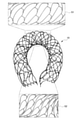
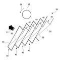
図6は、拡径したステント10(図4A参照)を略U字形に屈曲させた場合の各部の形状を示す図である。図7は、図6に示すステント10の各領域におけるセル40の状態を仮想的に平面状に展開した場合の模式図である。図7の中段の図は、引っ張り、圧縮のいずれの力も作用していない無負荷状態(図4Aの状態)のセル40を示している。図8は、図6に示す屈曲させたステント10の領域S1における連続したセル40の状態を仮想的に平面状に展開した場合の模式図である。図8では、上段にストラット50の断面を模式的に円で描いている。この円は、一つのストラット50に作用する応力を説明するために描いたものであり、実際のストラットの断面とは異なる。Next, the patency when the
FIG. 6 is a diagram showing the shape of each part when the expanded stent 10 (see FIG. 4A) is bent into a substantially U shape. FIG. 7 is a schematic view of the state of the
図6に示すように、拡径したステント10を略U字形に屈曲させると、屈曲した部分の背側(外側)の領域S1ではセル40が引っ張られた状態となる。このとき、領域S1に作用する応力は、図7の上段に示すように、セル40を構成する各ストラット50の接続点aにおいて、矢印51及び52の方向となる。そのため、図8に示すように、領域S1の連続したセル40は、矢印53の方向に引き延ばされるように変形する。すなわち、図8において、点線で示す無負荷状態のセル40のストラット50は、実線で示すように、矢印53の方向に引き延ばされるように変形(移動)する。このとき、ストラット50を断面方向から視てみると、図8の上段に示すように、ストラット50は、矢印54に示すように二方向に回るように変形する。ここで、図8の上段に示す矢印54で示す方向は、図8の下段に示す矢印53の方向に対応する。
As shown in FIG. 6, when the expanded
一方、図6において、屈曲した部分の腹側(内側)の領域S2では、セル40が圧縮された状態となる。このとき、領域S2に作用する応力は、図7の下段に示すように、セル40のストラット50の接続点aにおいて、矢印55~57の方向となる。そのため、図示していないが、領域S2の連続したセル40は、ストラット50の間隔が狭くなる方向に引き延ばされるように変形する。
On the other hand, in FIG. 6, in the area S2 on the ventral side (inside) of the bent portion, the
次に、比較例1、比較例2及び第1実施形態の各ステントの応力に対する変形について説明する。
図9は、比較例1のステント20を仮想的に平面状に展開した展開図である。図10は、図9に示すステント20の部分拡大図である。図11は、屈曲させたステント20の背側の領域における連続したセル40の状態を仮想的に平面状に展開した場合の模式図である。図11は、屈曲させた比較例1のステント20の背側の領域における連続したセル40の状態を仮想的に平面状に展開した場合の模式図である。Next, the deformation of each stent of Comparative Example 1, Comparative Example 2 and the first embodiment with respect to stress will be described.
FIG. 9 is a development view in which the
図9に示すように、比較例1のステント20は、軸線方向LDに並んで配置される複数の環状体21と、軸線方向LDに隣り合う環状体21を接続する接続要素22と、を備えている。比較例1のステント20を軸線方向LDに対して垂直な径方向RDに視たときに、環状体21の環方向CDは、径方向RDと略一致している。
As shown in FIG. 9, the
図10に示すように、比較例1のステント20は、略V字形状のV字要素23を周方向に複数接続して形成される波線状パターンを有する。V字要素23は、2つの脚部24を頂部25で連結して形成されている。V字要素23において、頂部25は、軸線方向LDにおいて同じ方向に向いており、周方向において隣り合うV字要素23の脚部24同士が接続されることにより、波線状パターンは形成されている。
As shown in FIG. 10, the
各接続要素22の長手方向の2つの端部22a、22bは、それぞれ軸線方向LDにおいて隣り合う2つV字要素23を接続している。接続要素22の一方の端部22aは、軸線方向LDに隣り合うV字要素23であって、波線状パターンに沿って隣り合う2つのV字要素23のそれぞれの脚部24と接続している。また、接続要素22の他方の端部22bは、軸線方向LDに隣り合うV字要素23の頂部25と接続している。このように、比較例1のステント20は、すべての頂部25が接続要素22と接続されている。そのため、比較例1のステント20は、自由端のないクローズドセル構造を有している。
The two
比較例1のステント20を実施形態のステント10(図4参照)と同様に拡径し、略U字形に屈曲させると、背側の領域ではセル40が引っ張られた状態となる。このとき、背側の領域の連続したセル40は、図11に示すように、矢印55の方向に斜めに変形する。すなわち、図11において、点線で示す無負荷状態のセル40のストラット50は、実線で示すように変形(移動)することになる。このとき、ストラット50を断面方向から見てみると、図11の上段に示すように、ストラット50は、矢印56の一方向に回るように変形する。
When the
ここで、図11の上段に示す矢印56で示す方向は、図11の下段に示す矢印55の方向に対応する。このように、比較例1のステント20において、屈曲した部分の背側の領域では、セル40の変形が小さく、且つ、ストラット50を断面方向から視たときに変形する方向も一方向のみとなる。そのため、比較例1のステント20において、背側の領域に作用する応力を吸収するための変形量は、実施形態のステント10よりも小さくなる。すなわち、比較例1のステント20では、屈曲した部分に作用する応力により、背側の領域に潰れが発生しやすいことになる。比較例1のステント20において、屈曲した部分の腹側の領域についても同様であり、屈曲した部分に作用する応力により、潰れが発生しやすい構造となっている。
Here, the direction indicated by the
図12は、比較例2のステント30を仮想的に平面状に展開した展開図である。図13は、図12に示すステント30の部分拡大図である。図14は、屈曲させたステント30の背側の領域における連続したセル40の状態を仮想的に平面状に展開した場合の模式図である。
FIG. 12 is a development view in which the
図12に示すように、比較例2のステント30は、軸線方向LDに並んで配置される複数の環状体31と、軸線方向LDに隣り合う環状体31を接続する接続要素32と、を備えている。比較例2のステント30を軸線方向LDに対して垂直な径方向RDに視たときに、環状体31の環方向CDは、径方向RDに対して傾斜している。
As shown in FIG. 12, the
図13に示すように、比較例2のステント30は、略V字形状のV字要素33を環方向CDに複数接続して形成される波線状パターンを有する。V字要素33は、2つの脚部34を頂部35で連結して形成されている。V字要素33において、頂部35は、軸線方向LDにおいて同じ方向に向いており、環方向CDにおいて隣り合うV字要素33の脚部34同士が接続されて、波線状パターンは形成されている。
As shown in FIG. 13, the
各接続要素32の長手方向の2つの端部32a、32bは、それぞれ軸線方向LDにおいて隣り合う2つV字要素33を接続している。接続要素32の一方の端部32aは、軸線方向LDに隣り合うV字要素33であって、環方向CDに沿って延びる波線状パターンに沿って隣り合う2つのV字要素33のそれぞれの脚部34と接続している。また、接続要素32の他方の端部32bは、軸線方向LDに隣り合うV字要素33の頂部35と接続している。このように、比較例2のステント30は、すべての頂部35が接続要素32と接続されている。そのため、比較例2のステント30は、自由端のないクローズドセル構造を有している。
The two
比較例2のステント30を実施形態のステント10(図4A参照)と同様に拡径し、略U字形に屈曲させると、背側の領域ではセルが引っ張られた状態となる。このとき、背側の領域の連続したセルは、図14に示すように、矢印57の方向に斜めに変形する。すなわち、図14において、点線で示す無負荷状態のセルのストラット50は、実線で示すように変形(移動)することになる。このとき、ストラット50を断面方向から見てみると、図14の上段に示すように、ストラット50は、矢印58の一方向に回るように変形する。
When the
ここで、図14の上段に示す矢印58の方向は、図14の下段に示す矢印57の方向に対応する。このように、比較例2のステント30において、屈曲した部分の背側の領域では、セルの変形が小さく、且つ、ストラット50を断面方向から視たときに変形する方向も一方向のみとなる。そのため、比較例2のステント30において、背側の領域に作用する応力を吸収するための変形量は、実施形態のステント10よりも小さくなる。すなわち、比較例2のステント30では、屈曲した部分に作用する応力により、背側の領域に潰れが発生しやすいことになる。比較例2のステント30において、屈曲した部分の腹側の領域についても同様であり、屈曲した部分に作用する応力により、潰れが発生しやすい構造となっている。
Here, the direction of the
次に、比較例1、比較例2及び実施形態の各ステントの開存性について説明する。
図15A~図15Cは、それぞれ比較例1、比較例2及び実施形態の各ステントの開存性を説明する図である。図15A~図15Cは、比較例1、比較例2及び実施形態のそれぞれのステントを同一の径となるまで拡径し、略U字形に屈曲させたときの断面形状を示している。図15A~図15Cの上段は、破線で示す曲がりの中心部分での断面形状を示している。図15A~図15Cの下段は、ステントを略U字形に屈曲させたときの外観を示している。Next, the patency of each stent of Comparative Example 1, Comparative Example 2, and the embodiment will be described.
15A to 15C are diagrams illustrating the patency of each stent of Comparative Example 1, Comparative Example 2, and the embodiment, respectively. 15A to 15C show the cross-sectional shapes of the stents of Comparative Example 1, Comparative Example 2 and the embodiment when they are expanded to the same diameter and bent into a substantially U shape. The upper part of FIGS. 15A to 15C shows the cross-sectional shape at the central portion of the bend shown by the broken line. The lower part of FIGS. 15A to 15C shows the appearance when the stent is bent into a substantially U shape.
図15Aに示す比較例1のステント20及び図15Bに示す比較例2のステント30は、いずれも断面が略楕円形に潰れるキンクが発生しており、屈曲に対して開存性が低いことが明らかとなった。これは、比較例1のステント20及び比較例2のステント30では、屈曲による応力に対して、各セルが一方向にしか変形しないためと考えられる。一方、図15Cに示す実施形態のステント10は、断面の潰れが少なく、屈曲に対して高い開存性を有することが明らかとなった。これは、実施形態のステント10では、屈曲による応力に対して、各セルが二方向に変形するためと考えられる。
Both the
上述したように、第1実施形態のステント10は、波線状パターンを形成する複数の波形単位14に自由端(第2頂部19)を備えているため、ステント10を屈曲させたときに、自由端に接続された2つの脚部が互いに離れる方向に移動して、セル全体を二方向に変形させることができる。したがって、実施形態のステント10は、屈曲に対して高い開存性を有している。
As described above, since the
第1実施形態のステント10は、カテーテルへの挿入方向において、自由端となる第2頂部19が遠位側に突出するように形成されている。本構成によれば、ステント10をカテーテルに再収納した際に、自由端となる第2頂部19の略V字形の突端が、カテーテルの挿入口と対向しないため、ステント10をカテーテルに容易に再収納することができる。
The
第1実施形態のステント10において、波形単位14の第3脚部17と、軸線周りに隣り合う波形単位14の第1脚部15とは、その間にスリットSが形成されるように、端部同士において連結されている。そのため、第1実施形態のステント10は、第1脚部15に連結された第3脚部17と、この第3脚部17と第2頂部19で連結された第2脚部16とを、より大きく変形させることができる。
In the
(第2実施形態)
次に、第2実施形態のステント10Aについて説明する。第2実施形態の説明及び図面において、第1実施形態と同等の部材等には、第1実施形態と同一の符号を付し、重複する説明を省略する。(Second Embodiment)
Next, the
図16は、第2実施形態のステント10Aを仮想的に平面状に展開した展開図である。図17は、ステント10Aを縮径した状態を示す展開図である。図18は、拡径したステント10Aを略U字形に屈曲させた場合の形状を示す図である。
FIG. 16 is a development view in which the
図16に示すように、第2実施形態のステント10Aにおいて、接続要素12の長さL4は、第2脚部16の長さL2よりも短く設定されている。具体的には、接続要素12の長さL4は、L4/L2の値において、例えば、0.7~0.9程度となるように設定されている。接続要素12の長さL4及び第2脚部16の長さL2は、最短距離(直線距離)で測定される。
As shown in FIG. 16, in the
また、第2実施形態のステント10Aにおいて、複数の波形単位14は、径方向RDに沿って接続されている。すなわち、第2実施形態のステント10Aを軸線方向LDに対して垂直な径方向RDに視たときに、環状体11の環方向CDは、径方向RDと略一致している。
Further, in the
第2実施形態のステント10Aにおいて、接続要素12の長さL4は、第2脚部16の長さL2よりも短く設定されている。本構成によれば、軸線方向LDにおいて隣接する波形単位14同士の間隔が短くなるため、軸線方向LDの単位長さ当たりの波形単位14の数を増やすことができる。このように、波形単位14の数が増えると、軸線方向LDの単位長さ当たりの表面積が増えるため、ステント10Aの血管保持性能をより向上させることができる。
In the
第2実施形態のステント10Aにおいて、複数の波形単位14は、径方向RDに沿って接続されている。そのため、ステントの加工時に、レーザ加工を施した細径チューブを仕上がり径まで拡径する工程において、ストラット内に作用する応力は、径方向RDに均一に伝達される。このように、ストラット内に作用する応力が径方向RDに均一に伝達されると、応力の局所的な不均一によるストラットの捻じれ等が起こりにくくなるため、円周方向において、より均等な拡張形状を得ることができる。また、第2実施形態のステント10Aにおいては、複数の波形単位14を径方向RDに沿ってパターニングできるため、加工性にも優れている。
In the
第2実施形態のステント10Aにおいて、波形単位14の基本的な構造は、第1実施形態と同じである。すなわち、図17に示すように、波形単位14において、第2頂部19の略V字形の突端は、ステント10Aのカテーテル(不図示)への挿入方向(LD2からLD1)において、いずれも遠位側LD2に突出するように形成されている。そのため、第2実施形態のステント10Aにおいても、第1実施形態と同様に、カテーテルに容易に再収納することができる。また、第2実施形態のステント10Aは、図17に示すように、縮径した状態において、第2頂部19が接続要素12と重なりにくいため、拡径時にステント10Aをより均等に展開させることができる。
In the
なお、第2実施形態のステント10Aにおいても、図18に示すように、略U字形の屈曲させたときに、自由端となる第2頂部19に接続された2つの脚部16、17が互いに離れる方向に移動して、セル全体を二方向に変形させることができるため、屈曲に対して高い開存性を有している。
Also in the
以上、本発明に係るステントの実施形態について説明したが、本開示は、前述した実施形態に限定されるものではなく、後述する変形形態のように種々の変形や変更が可能であって、それらも本開示の技術的範囲内に含まれる。また、実施形態に記載した効果は、本開示から生じる最も好適な効果を列挙したに過ぎず、実施形態に記載したものに限定されない。なお、上述の実施形態及び後述する変形形態は、適宜に組み合わせて用いることもできるが、詳細な説明は省略する。 Although the embodiment of the stent according to the present invention has been described above, the present disclosure is not limited to the above-described embodiment, and various deformations and changes are possible as in the deformation form described later. Is also included within the technical scope of this disclosure. Moreover, the effects described in the embodiments are merely a list of the most suitable effects resulting from the present disclosure, and are not limited to those described in the embodiments. The above-described embodiment and the modified form described later may be used in combination as appropriate, but detailed description thereof will be omitted.
図19は、第1変形形態のステント10Bを仮想的に平面状に展開した展開図である。第1変形形態のステント10Bは、環状体11の環方向CDが径方向RDに対して傾斜する方向が第1実施形態のステント10と相違する。具体的には、第1変形形態のステント10Bを、軸線方向LDに対して垂直な径方向RDに視たときに、環状体11の環方向CDは、径方向RDに対して角度-θだけ傾斜している。図19に示すように、環状体11が径方向RDに対して角度-θだけ傾斜している形態において、波形単位14の第1脚部15の長さL1と第2脚部16の長さL2とを足した長さは、第3脚部17の長さL3よりも短くなる。図19に示すように、環状体11の環方向CDが径方向RDに対して傾斜する方向は、第1実施形態のステント10(図2参照)と逆であってもよい。本構成においても、第1実施形態のステント10と同様の効果を得ることができる。なお、第1変形形態の構成は、第2実施形態のステント10Aにも適用することができる。
FIG. 19 is a developed view of the first modified form of the
図20A~図20Cは、第2変形形態の波形単位14の部分拡大図である。第1及び第2実施形態において、接続要素12と波形単位14との接続部分には、図20A~図20Cに示すような接続形状を適用することができる。図20A~図20Cは、図2に示す波形単位14の領域A1又はA2のいずれかの接続部分に適用可能な形状を示している。以下、図2の領域A1に示す接続部分を例として説明する。領域A1は、接続要素12の第1端部12aと、波形単位14の第1脚部15の第2端部15b及び第3脚部17の第2端部17bとが接続される部分である。
20A to 20C are partially enlarged views of the
図20Aに示す接続形状において、接続要素12の第1端部12aは、第3脚部17の第2端部17bの側に接続されている。図20Bに示す接続形状において、接続要素12の第1端部12aは、第1脚部15の第2端部15bの側に接続されている。図20Cに示す接続形状において、接続要素12の第1端部12aは、第1脚部15の第2端部15bと第3脚部17の第2端部17bとの間に接続されている。第2変形形態の各図に示す接続形状は、例えば、ステントを屈曲させたときの力の伝達、内部及び表面に作用する応力の状態に応じて適宜に選択することができる。
In the connection shape shown in FIG. 20A, the
図21及び図22は、第3変形形態のステント10Cを仮想的に平面状に展開した展開図である。図21は、第3変形形態のステント10Cの第1の構成を示す展開図である。図21に示すように、第3変形形態のステント10Cの第1の構成において、軸線方向LDに隣り合う環状体11を接続する接続要素12は、略S字形の波線状パターンとなるように形成されている。図22は、第3変形形態のステント10Cの第2の構成を示す展開図である。図22に示すように、第3変形形態のステント10Cの第2の構成において、軸線方向LDに隣り合う環状体11を接続する接続要素12は、略S字形の波線状パターンが2回連続するように形成されている。第2の構成の接続要素12において、略S字形の波線状パターンが3回以上連続する構成としてもよい。第3変形形態の各図に示す接続要素12の形状は、例えば、ステントを屈曲させたときの力の伝達、内部及び表面に作用する応力の状態に応じて適宜に選択することができる。
21 and 22 are development views of the
図23は、第4変形形態のステント10Dを仮想的に平面状に展開した展開図である。図23に示すように、波形単位14を構成する第1脚部15、第2脚部16及び第3脚部17と、環状体11同士を接続する接続要素12は、ストラットの太さ(例えば、最大径)がそれぞれ異なっていてもよい。図23のステント10Dは、より柔軟性を高めるために、第1脚部15、第2脚部16及び第3脚部17の太さに対して、接続要素12の太さを細くした例を示している。第1脚部15、第2脚部16、第3脚部17及び接続要素12におけるストラットの太さは、ステントを屈曲させたときの力の伝達、内部及び表面に作用する応力の状態に応じて適宜に選択することができる。なお、第4変形形態のステント10Dにおいては、接続要素12を細くする例について示したが、ストラットの太さを変更するのは、第1脚部15、第2脚部16、第3脚部17及び接続要素12のいずれか一つ又は複数であってもよい。
FIG. 23 is a developed view of the
図24は、第5変形形態のステント10Eを仮想的に平面状に展開した展開図である。図24に示すように、第5変形形態のステント10Eは、径方向RDの2つの接続点(×)の間に、接続要素帯L12が2つ設けられている。図24において、2つの接続点(×)は、略円筒形状のステント10Dの周方向における仮想的な接続位置を示している。また、接続要素帯L12は、環方向CDに沿って配置された複数の接続要素12の列を示している。第5変形形態のステント10Eは、径方向RDの2つの接続点(×)の間に、接続要素帯L12が2つ設けられている。そのため、第5変形形態のステント10Eは、径方向RDの2つの接続点(×)の間に、接続要素帯L12が1つ設けられている構成(例えば、図2参照)に比べて、ステントの表面積、セル密度を増加させることができる。なお、図24に示すステント10Eにおいて、径方向RDの2つの接続点(×)の間に、接続要素帯L12を3つ以上設けた構成としてもよい。
FIG. 24 is a developed view of the fifth modified form of the
図25は、第6変形形態のステント10Fを仮想的に平面状に展開した展開図である。図25は、ステント10Fの軸線方向LDの略中央から近位側LD1の端部までの範囲を示している。図25に示すように、ステント10Fは、近位側LD1の端部にマーカー保持部13を備えている。マーカー保持部13は、マーカー130(後述)を保持する部分である。なお、図25においては、ステント10Fの近位側LD1の端部にマーカー保持部13を3つ設けた例を示すが、マーカー保持部13の数は、図25の例に限定されない。
FIG. 25 is a developed view of the
マーカー保持部13は、長手方向の中心部分に沿ってスリット13aが形成されている。スリット13aは、カシメ加工によりマーカー130の略中央部分と締結される部分である。なお、図25に示す3つのマーカー保持部13のうち、左端のマーカー保持部13は、マーカー130が締結される前の状態を示している。
The
第6変形形態のステント10Fに用いられるマーカー130は、略円筒形に形成されている。マーカー130においては、一方の端部に略半円形の頭部131が形成され、他方の端部に開口部132が形成されている。ステント10Fの近位側LD1に保持されるマーカー130において、頭部131は、ステント10Fをカテーテル(不図示)に再収納する際の挿入方向(LD2からLD1)に位置している。マーカー130は、第1実施形態で説明したマーカー100(図4B参照)と同じく、放射線不透過の材料により形成される。
The
図25に示すように、ステント10Fのマーカー保持部13に、マーカー130を開口部132側から差し込み、カシメ加工を施すことにより、ステント10Fのマーカー保持部13とマーカー130とを締結することができる。図示していないが、ステント10Fの軸線方向LDの略中央から遠位側LD2の端部までの範囲についても、図25と同様に構成されている。
As shown in FIG. 25, the
第6変形形態の構成によれば、ステント10Fをカテーテルに再収納する際に、マーカー130の挿入方向となる側に略半円形の頭部131が位置しているため、カテーテルにステント10Fをより容易に再収納することができる。
According to the configuration of the sixth modified form, when the
10,10A,10B,10C,10D,10E,10F ステント
11 環状体(波線状パターン体)
12 接続要素
12a 第1端部
12b 第2端部
14 波形単位
15 第1脚部
15a 第1端部
15b 第2端部
16 第2脚部
16a 第1端部
16b 第2端部
17 第3脚部
17a 第1端部
17b 第2端部
18 第1頂部
19 第2頂部
100 マーカー10, 10A, 10B, 10C, 10D, 10E,
12
Claims (7)
前記波線状パターンは、第1脚部、第2脚部及び第3脚部と、前記第1脚部の一方の第1端部と前記第2脚部の一方の第1端部とを連結する第1頂部と、前記第2脚部の他方の第2端部と前記第3脚部の一方の第1端部とを連結する第2頂部とを備える複数の波形単位により形成され、前記第3脚部の他方の第2端部は、軸線周りに隣り合う前記波形単位の前記第1脚部の他方の第2端部と接続されており、
前記接続要素の一方の第1端部は、軸線方向において隣り合う一方の前記波形単位の前記第1頂部に接続され、前記接続要素の他方の第2端部は、軸線方向に隣り合う他方の前記波形単位の前記第1脚部の前記第2端部と接続される、
ステント。A plurality of wavy pattern bodies having a wavy pattern and arranged side by side in the axial direction, and a plurality of connecting elements arranged around the axis and connecting the adjacent wavy pattern bodies are provided, and the diameter is reduced. It is a stent that is inserted into the catheter in the state of being inserted.
The wavy pattern connects the first leg portion, the second leg portion, and the third leg portion, the first end portion of one of the first leg portions, and the first end portion of one of the second leg portions. It is formed by a plurality of corrugated units including a first top portion to be formed, a second top portion connecting the other second end portion of the second leg portion and one first end portion of the third leg portion, and said. The other second end of the third leg is connected to the other second end of the first leg of the waveform unit adjacent to the axis.
One first end of the connecting element is connected to the first apex of one of the corrugated units adjacent in the axial direction, and the other second end of the connecting element is the other adjacent in the axial direction. Connected to the second end of the first leg of the waveform unit,
Stent.
請求項1に記載のステント。The second apex of the corrugated unit is formed to project distally in the direction of insertion of the stent into the catheter.
The stent according to claim 1.
請求項1又は2に記載のステント。The third leg and the first leg of the corrugated unit adjacent to each other around the axis are connected to each other so that a slit is formed between them.
The stent according to claim 1 or 2.
請求項1~3までのいずれか一項に記載のステント。When viewed from a radial direction perpendicular to the axial direction, the ring direction of the wavy pattern of the wavy pattern body is inclined with respect to the radial direction.
The stent according to any one of claims 1 to 3.
請求項4に記載のステント。The total length of the length of the first leg and the length of the second leg is longer than the length of the third leg.
The stent according to claim 4.
請求項4に記載のステント。The sum of the length of the first leg and the length of the second leg is shorter than the length of the third leg.
The stent according to claim 4.
軸線方向に対して垂直な径方向から視たときに、前記波線状パターン体の前記波線状パターンの環方向は、前記径方向と略一致している、
請求項1~3までのいずれか一項に記載のステント。The length of the connecting element is shorter than the length of the second leg.
When viewed from a radial direction perpendicular to the axial direction, the ring direction of the wavy pattern of the wavy pattern body substantially coincides with the radial direction.
The stent according to any one of claims 1 to 3.
Applications Claiming Priority (3)
| Application Number | Priority Date | Filing Date | Title |
|---|---|---|---|
| JP2020136261 | 2020-08-12 | ||
| JP2020136261 | 2020-08-12 | ||
| PCT/JP2021/029676 WO2022034905A1 (en) | 2020-08-12 | 2021-08-11 | Stent |
Publications (2)
| Publication Number | Publication Date |
|---|---|
| JPWO2022034905A1 JPWO2022034905A1 (en) | 2022-02-17 |
| JP7029578B1 true JP7029578B1 (en) | 2022-03-03 |
Family
ID=80248007
Family Applications (1)
| Application Number | Title | Priority Date | Filing Date |
|---|---|---|---|
| JP2021571402A Active JP7029578B1 (en) | 2020-08-12 | 2021-08-11 | Stent |
Country Status (11)
| Country | Link |
|---|---|
| US (2) | US11590009B2 (en) |
| EP (1) | EP4014933A4 (en) |
| JP (1) | JP7029578B1 (en) |
| KR (1) | KR102558760B1 (en) |
| CN (2) | CN116785038A (en) |
| AU (1) | AU2021326319B2 (en) |
| BR (1) | BR112022004391A2 (en) |
| CA (1) | CA3154198C (en) |
| MX (1) | MX2022003630A (en) |
| NZ (1) | NZ786736A (en) |
| WO (1) | WO2022034905A1 (en) |
Families Citing this family (1)
| Publication number | Priority date | Publication date | Assignee | Title |
|---|---|---|---|---|
| WO2024080365A1 (en) * | 2022-10-14 | 2024-04-18 | 株式会社Bolt Medical | Distal stabilizer |
Citations (4)
| Publication number | Priority date | Publication date | Assignee | Title |
|---|---|---|---|---|
| US20090024205A1 (en) * | 2007-07-19 | 2009-01-22 | Bay Street Medical | Radially Expandable Stent |
| JP2013517913A (en) * | 2010-01-30 | 2013-05-20 | アボット カーディオヴァスキュラー システムズ インコーポレイテッド | Compressible polymer scaffold |
| WO2015125320A1 (en) * | 2014-02-19 | 2015-08-27 | 株式会社World Medish | Highly flexible stent |
| WO2015145596A1 (en) * | 2014-03-25 | 2015-10-01 | 株式会社World Medish Technology | Flexible stent |
Family Cites Families (13)
| Publication number | Priority date | Publication date | Assignee | Title |
|---|---|---|---|---|
| US6783543B2 (en) * | 2000-06-05 | 2004-08-31 | Scimed Life Systems, Inc. | Intravascular stent with increasing coating retaining capacity |
| US5948016A (en) | 1997-09-25 | 1999-09-07 | Jang; G. David | Intravascular stent with non-parallel slots |
| JP4473390B2 (en) | 2000-01-07 | 2010-06-02 | 川澄化学工業株式会社 | Stent and stent graft |
| JP2004267492A (en) * | 2003-03-10 | 2004-09-30 | Nipro Corp | Flexible stent with superior retention of blood vessel diameter |
| JP4928891B2 (en) * | 2006-09-29 | 2012-05-09 | テルモ株式会社 | Self-expanding in-vivo stent |
| WO2007058190A1 (en) | 2005-11-16 | 2007-05-24 | Tokai University Educational System | Controlled drug release composition and drug releasing medical device |
| US7988723B2 (en) | 2007-08-02 | 2011-08-02 | Flexible Stenting Solutions, Inc. | Flexible stent |
| EP2258414A3 (en) | 2007-09-04 | 2014-08-27 | Japan Stent Technology Co., Ltd. | Sustained drug-releasing stent |
| US9345602B2 (en) | 2010-09-23 | 2016-05-24 | Abbott Cardiovascular Systems Inc. | Processes for making crush recoverable polymer scaffolds |
| CN202740162U (en) * | 2012-02-27 | 2013-02-20 | 江苏省华星医疗器械实业有限公司 | Novel vessel rack |
| JP2017164323A (en) * | 2016-03-16 | 2017-09-21 | テルモ株式会社 | Stent |
| JP2018046934A (en) * | 2016-09-20 | 2018-03-29 | テルモ株式会社 | Stent |
| CA3036780A1 (en) * | 2016-10-04 | 2018-04-12 | Yasuhiro Shobayashi | Flexible stent |
-
2021
- 2021-08-11 CN CN202310308468.6A patent/CN116785038A/en active Pending
- 2021-08-11 JP JP2021571402A patent/JP7029578B1/en active Active
- 2021-08-11 WO PCT/JP2021/029676 patent/WO2022034905A1/en unknown
- 2021-08-11 US US17/753,584 patent/US11590009B2/en active Active
- 2021-08-11 EP EP21855984.7A patent/EP4014933A4/en active Pending
- 2021-08-11 CA CA3154198A patent/CA3154198C/en active Active
- 2021-08-11 CN CN202180005258.9A patent/CN114364351B/en active Active
- 2021-08-11 NZ NZ786736A patent/NZ786736A/en unknown
- 2021-08-11 BR BR112022004391A patent/BR112022004391A2/en unknown
- 2021-08-11 MX MX2022003630A patent/MX2022003630A/en unknown
- 2021-08-11 KR KR1020227008704A patent/KR102558760B1/en active IP Right Grant
- 2021-08-11 AU AU2021326319A patent/AU2021326319B2/en active Active
-
2023
- 2023-02-01 US US18/163,223 patent/US20230181341A1/en active Pending
Patent Citations (4)
| Publication number | Priority date | Publication date | Assignee | Title |
|---|---|---|---|---|
| US20090024205A1 (en) * | 2007-07-19 | 2009-01-22 | Bay Street Medical | Radially Expandable Stent |
| JP2013517913A (en) * | 2010-01-30 | 2013-05-20 | アボット カーディオヴァスキュラー システムズ インコーポレイテッド | Compressible polymer scaffold |
| WO2015125320A1 (en) * | 2014-02-19 | 2015-08-27 | 株式会社World Medish | Highly flexible stent |
| WO2015145596A1 (en) * | 2014-03-25 | 2015-10-01 | 株式会社World Medish Technology | Flexible stent |
Also Published As
| Publication number | Publication date |
|---|---|
| CN114364351A (en) | 2022-04-15 |
| CN116785038A (en) | 2023-09-22 |
| NZ786736A (en) | 2022-07-29 |
| CA3154198C (en) | 2022-09-06 |
| CN114364351B (en) | 2023-04-14 |
| JPWO2022034905A1 (en) | 2022-02-17 |
| CA3154198A1 (en) | 2022-02-17 |
| EP4014933A4 (en) | 2022-11-09 |
| MX2022003630A (en) | 2022-12-08 |
| BR112022004391A2 (en) | 2024-02-27 |
| AU2021326319A1 (en) | 2022-04-21 |
| US20230181341A1 (en) | 2023-06-15 |
| US11590009B2 (en) | 2023-02-28 |
| WO2022034905A1 (en) | 2022-02-17 |
| EP4014933A1 (en) | 2022-06-22 |
| KR102558760B1 (en) | 2023-07-24 |
| US20220265447A1 (en) | 2022-08-25 |
| KR20220039830A (en) | 2022-03-29 |
| AU2021326319B2 (en) | 2022-05-12 |
Similar Documents
| Publication | Publication Date | Title |
|---|---|---|
| JP6764960B2 (en) | Stents and Catheter Stent Systems | |
| JP7029578B1 (en) | Stent | |
| RU2784857C1 (en) | Stent | |
| JP2019122556A (en) | Stent | |
| WO2022085313A1 (en) | Stent | |
| CA2883013C (en) | Highly flexible stent | |
| JPWO2012132753A1 (en) | Stent and stent delivery system | |
| JP2019122651A (en) | Stent |
Legal Events
| Date | Code | Title | Description |
|---|---|---|---|
| A621 | Written request for application examination |
Free format text: JAPANESE INTERMEDIATE CODE: A621 Effective date: 20211130 |
|
| A871 | Explanation of circumstances concerning accelerated examination |
Free format text: JAPANESE INTERMEDIATE CODE: A871 Effective date: 20211130 |
|
| AA64 | Notification of invalidation of claim of internal priority (with term) |
Free format text: JAPANESE INTERMEDIATE CODE: A241764 Effective date: 20211214 |
|
| A521 | Request for written amendment filed |
Free format text: JAPANESE INTERMEDIATE CODE: A523 Effective date: 20211215 |
|
| TRDD | Decision of grant or rejection written | ||
| A01 | Written decision to grant a patent or to grant a registration (utility model) |
Free format text: JAPANESE INTERMEDIATE CODE: A01 Effective date: 20220201 |
|
| A61 | First payment of annual fees (during grant procedure) |
Free format text: JAPANESE INTERMEDIATE CODE: A61 Effective date: 20220218 |
|
| R150 | Certificate of patent or registration of utility model |
Ref document number: 7029578 Country of ref document: JP Free format text: JAPANESE INTERMEDIATE CODE: R150 |
|
| R350 | Written notification of registration of transfer |
Free format text: JAPANESE INTERMEDIATE CODE: R350 |