JP7026645B2 - Clot drainage and visualization device and usage - Google Patents
Clot drainage and visualization device and usage Download PDFInfo
- Publication number
- JP7026645B2 JP7026645B2 JP2018568173A JP2018568173A JP7026645B2 JP 7026645 B2 JP7026645 B2 JP 7026645B2 JP 2018568173 A JP2018568173 A JP 2018568173A JP 2018568173 A JP2018568173 A JP 2018568173A JP 7026645 B2 JP7026645 B2 JP 7026645B2
- Authority
- JP
- Japan
- Prior art keywords
- clot
- drainer
- distal end
- visualization
- elongated body
- Prior art date
- Legal status (The legal status is an assumption and is not a legal conclusion. Google has not performed a legal analysis and makes no representation as to the accuracy of the status listed.)
- Active
Links
Images


Classifications
-
- A—HUMAN NECESSITIES
- A61—MEDICAL OR VETERINARY SCIENCE; HYGIENE
- A61B—DIAGNOSIS; SURGERY; IDENTIFICATION
- A61B1/00—Instruments for performing medical examinations of the interior of cavities or tubes of the body by visual or photographical inspection, e.g. endoscopes; Illuminating arrangements therefor
- A61B1/00163—Optical arrangements
- A61B1/00174—Optical arrangements characterised by the viewing angles
- A61B1/00181—Optical arrangements characterised by the viewing angles for multiple fixed viewing angles
-
- A—HUMAN NECESSITIES
- A61—MEDICAL OR VETERINARY SCIENCE; HYGIENE
- A61B—DIAGNOSIS; SURGERY; IDENTIFICATION
- A61B1/00—Instruments for performing medical examinations of the interior of cavities or tubes of the body by visual or photographical inspection, e.g. endoscopes; Illuminating arrangements therefor
- A61B1/00002—Operational features of endoscopes
- A61B1/00004—Operational features of endoscopes characterised by electronic signal processing
- A61B1/00009—Operational features of endoscopes characterised by electronic signal processing of image signals during a use of endoscope
- A61B1/000095—Operational features of endoscopes characterised by electronic signal processing of image signals during a use of endoscope for image enhancement
-
- A—HUMAN NECESSITIES
- A61—MEDICAL OR VETERINARY SCIENCE; HYGIENE
- A61B—DIAGNOSIS; SURGERY; IDENTIFICATION
- A61B1/00—Instruments for performing medical examinations of the interior of cavities or tubes of the body by visual or photographical inspection, e.g. endoscopes; Illuminating arrangements therefor
- A61B1/00002—Operational features of endoscopes
- A61B1/0002—Operational features of endoscopes provided with data storages
-
- A—HUMAN NECESSITIES
- A61—MEDICAL OR VETERINARY SCIENCE; HYGIENE
- A61B—DIAGNOSIS; SURGERY; IDENTIFICATION
- A61B1/00—Instruments for performing medical examinations of the interior of cavities or tubes of the body by visual or photographical inspection, e.g. endoscopes; Illuminating arrangements therefor
- A61B1/00064—Constructional details of the endoscope body
- A61B1/00071—Insertion part of the endoscope body
- A61B1/0008—Insertion part of the endoscope body characterised by distal tip features
- A61B1/00087—Tools
-
- A—HUMAN NECESSITIES
- A61—MEDICAL OR VETERINARY SCIENCE; HYGIENE
- A61B—DIAGNOSIS; SURGERY; IDENTIFICATION
- A61B1/00—Instruments for performing medical examinations of the interior of cavities or tubes of the body by visual or photographical inspection, e.g. endoscopes; Illuminating arrangements therefor
- A61B1/00147—Holding or positioning arrangements
- A61B1/00154—Holding or positioning arrangements using guiding arrangements for insertion
-
- A—HUMAN NECESSITIES
- A61—MEDICAL OR VETERINARY SCIENCE; HYGIENE
- A61B—DIAGNOSIS; SURGERY; IDENTIFICATION
- A61B1/00—Instruments for performing medical examinations of the interior of cavities or tubes of the body by visual or photographical inspection, e.g. endoscopes; Illuminating arrangements therefor
- A61B1/00163—Optical arrangements
- A61B1/00174—Optical arrangements characterised by the viewing angles
- A61B1/00179—Optical arrangements characterised by the viewing angles for off-axis viewing
-
- A—HUMAN NECESSITIES
- A61—MEDICAL OR VETERINARY SCIENCE; HYGIENE
- A61B—DIAGNOSIS; SURGERY; IDENTIFICATION
- A61B1/00—Instruments for performing medical examinations of the interior of cavities or tubes of the body by visual or photographical inspection, e.g. endoscopes; Illuminating arrangements therefor
- A61B1/012—Instruments for performing medical examinations of the interior of cavities or tubes of the body by visual or photographical inspection, e.g. endoscopes; Illuminating arrangements therefor characterised by internal passages or accessories therefor
- A61B1/015—Control of fluid supply or evacuation
-
- A—HUMAN NECESSITIES
- A61—MEDICAL OR VETERINARY SCIENCE; HYGIENE
- A61B—DIAGNOSIS; SURGERY; IDENTIFICATION
- A61B1/00—Instruments for performing medical examinations of the interior of cavities or tubes of the body by visual or photographical inspection, e.g. endoscopes; Illuminating arrangements therefor
- A61B1/06—Instruments for performing medical examinations of the interior of cavities or tubes of the body by visual or photographical inspection, e.g. endoscopes; Illuminating arrangements therefor with illuminating arrangements
- A61B1/07—Instruments for performing medical examinations of the interior of cavities or tubes of the body by visual or photographical inspection, e.g. endoscopes; Illuminating arrangements therefor with illuminating arrangements using light-conductive means, e.g. optical fibres
-
- A—HUMAN NECESSITIES
- A61—MEDICAL OR VETERINARY SCIENCE; HYGIENE
- A61B—DIAGNOSIS; SURGERY; IDENTIFICATION
- A61B1/00—Instruments for performing medical examinations of the interior of cavities or tubes of the body by visual or photographical inspection, e.g. endoscopes; Illuminating arrangements therefor
- A61B1/12—Instruments for performing medical examinations of the interior of cavities or tubes of the body by visual or photographical inspection, e.g. endoscopes; Illuminating arrangements therefor with cooling or rinsing arrangements
- A61B1/126—Instruments for performing medical examinations of the interior of cavities or tubes of the body by visual or photographical inspection, e.g. endoscopes; Illuminating arrangements therefor with cooling or rinsing arrangements provided with means for cleaning in-use
-
- A—HUMAN NECESSITIES
- A61—MEDICAL OR VETERINARY SCIENCE; HYGIENE
- A61B—DIAGNOSIS; SURGERY; IDENTIFICATION
- A61B1/00—Instruments for performing medical examinations of the interior of cavities or tubes of the body by visual or photographical inspection, e.g. endoscopes; Illuminating arrangements therefor
- A61B1/313—Instruments for performing medical examinations of the interior of cavities or tubes of the body by visual or photographical inspection, e.g. endoscopes; Illuminating arrangements therefor for introducing through surgical openings, e.g. laparoscopes
- A61B1/317—Instruments for performing medical examinations of the interior of cavities or tubes of the body by visual or photographical inspection, e.g. endoscopes; Illuminating arrangements therefor for introducing through surgical openings, e.g. laparoscopes for bones or joints, e.g. osteoscopes, arthroscopes
-
- A—HUMAN NECESSITIES
- A61—MEDICAL OR VETERINARY SCIENCE; HYGIENE
- A61B—DIAGNOSIS; SURGERY; IDENTIFICATION
- A61B17/00—Surgical instruments, devices or methods, e.g. tourniquets
- A61B17/22—Implements for squeezing-off ulcers or the like on the inside of inner organs of the body; Implements for scraping-out cavities of body organs, e.g. bones; Calculus removers; Calculus smashing apparatus; Apparatus for removing obstructions in blood vessels, not otherwise provided for
- A61B17/22004—Implements for squeezing-off ulcers or the like on the inside of inner organs of the body; Implements for scraping-out cavities of body organs, e.g. bones; Calculus removers; Calculus smashing apparatus; Apparatus for removing obstructions in blood vessels, not otherwise provided for using mechanical vibrations, e.g. ultrasonic shock waves
- A61B17/22012—Implements for squeezing-off ulcers or the like on the inside of inner organs of the body; Implements for scraping-out cavities of body organs, e.g. bones; Calculus removers; Calculus smashing apparatus; Apparatus for removing obstructions in blood vessels, not otherwise provided for using mechanical vibrations, e.g. ultrasonic shock waves in direct contact with, or very close to, the obstruction or concrement
-
- A—HUMAN NECESSITIES
- A61—MEDICAL OR VETERINARY SCIENCE; HYGIENE
- A61B—DIAGNOSIS; SURGERY; IDENTIFICATION
- A61B17/00—Surgical instruments, devices or methods, e.g. tourniquets
- A61B17/34—Trocars; Puncturing needles
- A61B17/3478—Endoscopic needles, e.g. for infusion
-
- A—HUMAN NECESSITIES
- A61—MEDICAL OR VETERINARY SCIENCE; HYGIENE
- A61B—DIAGNOSIS; SURGERY; IDENTIFICATION
- A61B17/00—Surgical instruments, devices or methods, e.g. tourniquets
- A61B17/34—Trocars; Puncturing needles
- A61B17/3494—Trocars; Puncturing needles with safety means for protection against accidental cutting or pricking, e.g. limiting insertion depth, pressure sensors
- A61B17/3496—Protecting sleeves or inner probes; Retractable tips
-
- A—HUMAN NECESSITIES
- A61—MEDICAL OR VETERINARY SCIENCE; HYGIENE
- A61B—DIAGNOSIS; SURGERY; IDENTIFICATION
- A61B8/00—Diagnosis using ultrasonic, sonic or infrasonic waves
- A61B8/08—Detecting organic movements or changes, e.g. tumours, cysts, swellings
- A61B8/0891—Detecting organic movements or changes, e.g. tumours, cysts, swellings for diagnosis of blood vessels
-
- A—HUMAN NECESSITIES
- A61—MEDICAL OR VETERINARY SCIENCE; HYGIENE
- A61B—DIAGNOSIS; SURGERY; IDENTIFICATION
- A61B8/00—Diagnosis using ultrasonic, sonic or infrasonic waves
- A61B8/12—Diagnosis using ultrasonic, sonic or infrasonic waves in body cavities or body tracts, e.g. by using catheters
-
- A—HUMAN NECESSITIES
- A61—MEDICAL OR VETERINARY SCIENCE; HYGIENE
- A61M—DEVICES FOR INTRODUCING MEDIA INTO, OR ONTO, THE BODY; DEVICES FOR TRANSDUCING BODY MEDIA OR FOR TAKING MEDIA FROM THE BODY; DEVICES FOR PRODUCING OR ENDING SLEEP OR STUPOR
- A61M25/00—Catheters; Hollow probes
- A61M25/10—Balloon catheters
-
- A—HUMAN NECESSITIES
- A61—MEDICAL OR VETERINARY SCIENCE; HYGIENE
- A61B—DIAGNOSIS; SURGERY; IDENTIFICATION
- A61B17/00—Surgical instruments, devices or methods, e.g. tourniquets
- A61B17/34—Trocars; Puncturing needles
-
- A—HUMAN NECESSITIES
- A61—MEDICAL OR VETERINARY SCIENCE; HYGIENE
- A61B—DIAGNOSIS; SURGERY; IDENTIFICATION
- A61B17/00—Surgical instruments, devices or methods, e.g. tourniquets
- A61B2017/0046—Surgical instruments, devices or methods, e.g. tourniquets with a releasable handle; with handle and operating part separable
- A61B2017/00473—Distal part, e.g. tip or head
-
- A—HUMAN NECESSITIES
- A61—MEDICAL OR VETERINARY SCIENCE; HYGIENE
- A61B—DIAGNOSIS; SURGERY; IDENTIFICATION
- A61B17/00—Surgical instruments, devices or methods, e.g. tourniquets
- A61B2017/00831—Material properties
- A61B2017/00867—Material properties shape memory effect
- A61B2017/00871—Material properties shape memory effect polymeric
-
- A—HUMAN NECESSITIES
- A61—MEDICAL OR VETERINARY SCIENCE; HYGIENE
- A61B—DIAGNOSIS; SURGERY; IDENTIFICATION
- A61B17/00—Surgical instruments, devices or methods, e.g. tourniquets
- A61B2017/00831—Material properties
- A61B2017/00902—Material properties transparent or translucent
- A61B2017/00907—Material properties transparent or translucent for light
-
- A—HUMAN NECESSITIES
- A61—MEDICAL OR VETERINARY SCIENCE; HYGIENE
- A61B—DIAGNOSIS; SURGERY; IDENTIFICATION
- A61B17/00—Surgical instruments, devices or methods, e.g. tourniquets
- A61B17/22—Implements for squeezing-off ulcers or the like on the inside of inner organs of the body; Implements for scraping-out cavities of body organs, e.g. bones; Calculus removers; Calculus smashing apparatus; Apparatus for removing obstructions in blood vessels, not otherwise provided for
- A61B2017/22051—Implements for squeezing-off ulcers or the like on the inside of inner organs of the body; Implements for scraping-out cavities of body organs, e.g. bones; Calculus removers; Calculus smashing apparatus; Apparatus for removing obstructions in blood vessels, not otherwise provided for with an inflatable part, e.g. balloon, for positioning, blocking, or immobilisation
- A61B2017/22062—Implements for squeezing-off ulcers or the like on the inside of inner organs of the body; Implements for scraping-out cavities of body organs, e.g. bones; Calculus removers; Calculus smashing apparatus; Apparatus for removing obstructions in blood vessels, not otherwise provided for with an inflatable part, e.g. balloon, for positioning, blocking, or immobilisation to be filled with liquid
-
- A—HUMAN NECESSITIES
- A61—MEDICAL OR VETERINARY SCIENCE; HYGIENE
- A61B—DIAGNOSIS; SURGERY; IDENTIFICATION
- A61B17/00—Surgical instruments, devices or methods, e.g. tourniquets
- A61B17/22—Implements for squeezing-off ulcers or the like on the inside of inner organs of the body; Implements for scraping-out cavities of body organs, e.g. bones; Calculus removers; Calculus smashing apparatus; Apparatus for removing obstructions in blood vessels, not otherwise provided for
- A61B2017/22051—Implements for squeezing-off ulcers or the like on the inside of inner organs of the body; Implements for scraping-out cavities of body organs, e.g. bones; Calculus removers; Calculus smashing apparatus; Apparatus for removing obstructions in blood vessels, not otherwise provided for with an inflatable part, e.g. balloon, for positioning, blocking, or immobilisation
- A61B2017/22065—Functions of balloons
-
- A—HUMAN NECESSITIES
- A61—MEDICAL OR VETERINARY SCIENCE; HYGIENE
- A61B—DIAGNOSIS; SURGERY; IDENTIFICATION
- A61B17/00—Surgical instruments, devices or methods, e.g. tourniquets
- A61B17/22—Implements for squeezing-off ulcers or the like on the inside of inner organs of the body; Implements for scraping-out cavities of body organs, e.g. bones; Calculus removers; Calculus smashing apparatus; Apparatus for removing obstructions in blood vessels, not otherwise provided for
- A61B2017/22072—Implements for squeezing-off ulcers or the like on the inside of inner organs of the body; Implements for scraping-out cavities of body organs, e.g. bones; Calculus removers; Calculus smashing apparatus; Apparatus for removing obstructions in blood vessels, not otherwise provided for with an instrument channel, e.g. for replacing one instrument by the other
-
- A—HUMAN NECESSITIES
- A61—MEDICAL OR VETERINARY SCIENCE; HYGIENE
- A61B—DIAGNOSIS; SURGERY; IDENTIFICATION
- A61B17/00—Surgical instruments, devices or methods, e.g. tourniquets
- A61B17/22—Implements for squeezing-off ulcers or the like on the inside of inner organs of the body; Implements for scraping-out cavities of body organs, e.g. bones; Calculus removers; Calculus smashing apparatus; Apparatus for removing obstructions in blood vessels, not otherwise provided for
- A61B2017/22079—Implements for squeezing-off ulcers or the like on the inside of inner organs of the body; Implements for scraping-out cavities of body organs, e.g. bones; Calculus removers; Calculus smashing apparatus; Apparatus for removing obstructions in blood vessels, not otherwise provided for with suction of debris
-
- A—HUMAN NECESSITIES
- A61—MEDICAL OR VETERINARY SCIENCE; HYGIENE
- A61B—DIAGNOSIS; SURGERY; IDENTIFICATION
- A61B17/00—Surgical instruments, devices or methods, e.g. tourniquets
- A61B17/32—Surgical cutting instruments
- A61B2017/320044—Blunt dissectors
-
- A—HUMAN NECESSITIES
- A61—MEDICAL OR VETERINARY SCIENCE; HYGIENE
- A61B—DIAGNOSIS; SURGERY; IDENTIFICATION
- A61B17/00—Surgical instruments, devices or methods, e.g. tourniquets
- A61B17/32—Surgical cutting instruments
- A61B2017/320044—Blunt dissectors
- A61B2017/320048—Balloon dissectors
-
- A—HUMAN NECESSITIES
- A61—MEDICAL OR VETERINARY SCIENCE; HYGIENE
- A61B—DIAGNOSIS; SURGERY; IDENTIFICATION
- A61B17/00—Surgical instruments, devices or methods, e.g. tourniquets
- A61B17/34—Trocars; Puncturing needles
- A61B17/3417—Details of tips or shafts, e.g. grooves, expandable, bendable; Multiple coaxial sliding cannulas, e.g. for dilating
- A61B17/3421—Cannulas
- A61B2017/3445—Cannulas used as instrument channel for multiple instruments
-
- A—HUMAN NECESSITIES
- A61—MEDICAL OR VETERINARY SCIENCE; HYGIENE
- A61B—DIAGNOSIS; SURGERY; IDENTIFICATION
- A61B17/00—Surgical instruments, devices or methods, e.g. tourniquets
- A61B17/34—Trocars; Puncturing needles
- A61B17/3417—Details of tips or shafts, e.g. grooves, expandable, bendable; Multiple coaxial sliding cannulas, e.g. for dilating
- A61B2017/3454—Details of tips
- A61B2017/3456—Details of tips blunt
-
- A—HUMAN NECESSITIES
- A61—MEDICAL OR VETERINARY SCIENCE; HYGIENE
- A61B—DIAGNOSIS; SURGERY; IDENTIFICATION
- A61B34/00—Computer-aided surgery; Manipulators or robots specially adapted for use in surgery
- A61B34/20—Surgical navigation systems; Devices for tracking or guiding surgical instruments, e.g. for frameless stereotaxis
- A61B2034/2046—Tracking techniques
- A61B2034/2055—Optical tracking systems
-
- A—HUMAN NECESSITIES
- A61—MEDICAL OR VETERINARY SCIENCE; HYGIENE
- A61B—DIAGNOSIS; SURGERY; IDENTIFICATION
- A61B2217/00—General characteristics of surgical instruments
- A61B2217/002—Auxiliary appliance
- A61B2217/005—Auxiliary appliance with suction drainage system
-
- A—HUMAN NECESSITIES
- A61—MEDICAL OR VETERINARY SCIENCE; HYGIENE
- A61B—DIAGNOSIS; SURGERY; IDENTIFICATION
- A61B2217/00—General characteristics of surgical instruments
- A61B2217/002—Auxiliary appliance
- A61B2217/007—Auxiliary appliance with irrigation system
-
- A—HUMAN NECESSITIES
- A61—MEDICAL OR VETERINARY SCIENCE; HYGIENE
- A61B—DIAGNOSIS; SURGERY; IDENTIFICATION
- A61B90/00—Instruments, implements or accessories specially adapted for surgery or diagnosis and not covered by any of the groups A61B1/00 - A61B50/00, e.g. for luxation treatment or for protecting wound edges
- A61B90/36—Image-producing devices or illumination devices not otherwise provided for
- A61B90/361—Image-producing devices, e.g. surgical cameras
-
- A—HUMAN NECESSITIES
- A61—MEDICAL OR VETERINARY SCIENCE; HYGIENE
- A61B—DIAGNOSIS; SURGERY; IDENTIFICATION
- A61B90/00—Instruments, implements or accessories specially adapted for surgery or diagnosis and not covered by any of the groups A61B1/00 - A61B50/00, e.g. for luxation treatment or for protecting wound edges
- A61B90/36—Image-producing devices or illumination devices not otherwise provided for
- A61B90/37—Surgical systems with images on a monitor during operation
-
- A—HUMAN NECESSITIES
- A61—MEDICAL OR VETERINARY SCIENCE; HYGIENE
- A61M—DEVICES FOR INTRODUCING MEDIA INTO, OR ONTO, THE BODY; DEVICES FOR TRANSDUCING BODY MEDIA OR FOR TAKING MEDIA FROM THE BODY; DEVICES FOR PRODUCING OR ENDING SLEEP OR STUPOR
- A61M25/00—Catheters; Hollow probes
- A61M25/10—Balloon catheters
- A61M2025/1043—Balloon catheters with special features or adapted for special applications
- A61M2025/1084—Balloon catheters with special features or adapted for special applications having features for increasing the shape stability, the reproducibility or for limiting expansion, e.g. containments, wrapped around fibres, yarns or strands
-
- A—HUMAN NECESSITIES
- A61—MEDICAL OR VETERINARY SCIENCE; HYGIENE
- A61M—DEVICES FOR INTRODUCING MEDIA INTO, OR ONTO, THE BODY; DEVICES FOR TRANSDUCING BODY MEDIA OR FOR TAKING MEDIA FROM THE BODY; DEVICES FOR PRODUCING OR ENDING SLEEP OR STUPOR
- A61M2210/00—Anatomical parts of the body
- A61M2210/06—Head
- A61M2210/0693—Brain, cerebrum
-
- A—HUMAN NECESSITIES
- A61—MEDICAL OR VETERINARY SCIENCE; HYGIENE
- A61M—DEVICES FOR INTRODUCING MEDIA INTO, OR ONTO, THE BODY; DEVICES FOR TRANSDUCING BODY MEDIA OR FOR TAKING MEDIA FROM THE BODY; DEVICES FOR PRODUCING OR ENDING SLEEP OR STUPOR
- A61M2230/00—Measuring parameters of the user
- A61M2230/20—Blood composition characteristics
- A61M2230/201—Glucose concentration
Description
(関連出願の参照による組み込み)
本出願は、2016年3月17日に出願された米国仮特許出願第62/309,918号及び2017年3月10日に出願された米国仮特許出願第62/470,095号に基づく優先権を主張するものであり、これらの開示内容は、その全てを本明細書に組み込むものとする。これらに対して優先権を持つかこれらを優先権の基礎とする関連するすべての出願は、参照として、その全てを本明細書に組み込むものとする。
(Incorporation by reference of related application)
This application is prioritized under US Provisional Patent Application No. 62 / 309,918 filed March 17, 2016 and US Provisional Patent Application No. 62 / 470,095 filed March 10, 2017. All of these disclosures are asserted and are incorporated herein by reference in their entirety. All related applications that have or have priority over them shall be incorporated herein by reference in their entirety.
この出願は、特に頭蓋内出血(ICH)の治療のような脳神経外科への応用のための凝血塊の排出装置、方法、及びシステムの実施形態を開示する。 This application discloses embodiments of a clot draining device, method, and system specifically for applications in neurosurgery such as the treatment of intracranial hemorrhage (ICH).
頭蓋内出血(ICH)は、頭蓋内で起こる出血であり、繊細な脳の組織が壊れ、脳の血液供給が制限され、脳の一部が圧迫され頭蓋骨内の構造を越えてしまう脳ヘルニアの可能性を引き起こす深刻な医学的緊急事態である。ICHは、脳内又は頭蓋骨と脳との間で血管が破裂したときにおこることがある。出血した血液は集まって凝血塊になり、脳内の循環に影響を与え、細胞死を引き起こす可能性がある。したがって、脳内の出血した血液及び/又は凝血塊を除去又は減少させることは、患者の回復にとって極めて重要である。 Intracranial hemorrhage (ICH) is an intracranial hemorrhage that can cause a brain herniation that disrupts delicate brain tissue, limits the blood supply of the brain, and compresses parts of the brain beyond the structure within the skull. It is a serious medical emergency that causes sexuality. ICH can occur when a blood vessel ruptures in the brain or between the skull and the brain. Bleeding blood collects into a clot that can affect circulation in the brain and cause cell death. Therefore, removing or reducing bleeding blood and / or clots in the brain is crucial for patient recovery.
凝血塊の除去は、カテーテルを用いた凝血塊の吸引、又は開頭術のような他の手段により行うことができる。開頭術を行っている間、脳神経外科医は頭蓋骨のかなりの部分を開いて、凝血塊を直接視覚により脳組織と区別し、凝血塊を安全に除去できるようにする。しかし、そのような外科手術は、回復時間が長くなるというリスクが高くなる。従って、ナビゲーション、視覚化、及び凝血塊の除去を容易にするための改善された方法及びツールが必要とされる。 Removal of the clot can be performed by aspiration of the clot using a catheter or by other means such as craniotomy. During a craniotomy, the neurosurgeon opens a significant portion of the skull to visually distinguish the clot from the brain tissue and allow the clot to be safely removed. However, such surgery increases the risk of longer recovery times. Therefore, improved methods and tools are needed to facilitate navigation, visualization, and removal of clots.
本開示の実施形態は、特に、頭蓋内出血(ICH)の結果生じた凝血塊の排出のための、凝血塊の排出のため及び視覚化のための装置、方法、及びシステムに関する。特定の実施形態では、視覚化を行う統合された凝血塊排出装置を含む。いくつかの実施形態では、統合された凝血塊排出装置は、視覚化センサと、近位端及び遠位端を有する細長い本体とを備える。細長い本体の遠位端は、侵襲性を最小にする体の開口部とするような、体の開口部を通過するように寸法決めしてもよい。この装置は、内蔵されたカメラと、脳の内部及び凝塊そのものを視覚化するための光源を含むことができる。特定の実施形態では、装置は、少なくとも1つの視覚化センサ及び細長い本体の遠位端に操縦性を与える統合された関節運動機構をさらに備えることができる。さらに、装置は、吸引及び灌注によって凝塊を排出するように構成されてもよい。 The embodiments of the present disclosure relate, in particular, to devices, methods, and systems for the elimination of clots resulting from intracranial hemorrhage (ICH), for the elimination of clots, and for visualization. In certain embodiments, it comprises an integrated clot drainer for visualization. In some embodiments, the integrated clot drainer comprises a visualization sensor and an elongated body with proximal and distal ends. The distal end of the elongated body may be sized to pass through the opening of the body, such as the opening of the body that minimizes invasiveness. The device can include a built-in camera and a light source for visualizing the inside of the brain and the agglomerates themselves. In certain embodiments, the device can further comprise at least one visualization sensor and an integrated range of motion mechanism that provides maneuverability to the distal end of the elongated body. In addition, the device may be configured to expel the agglomerates by suction and irrigation.
特定の実施形態では、統合された凝血塊排出装置は、
ハンドピースと、
ハンドルに固定された近位端と、遠位端との間の長手方向軸に沿って延びる細長い本体と、
組織及び/又は凝血塊を視覚化するように構成された細長い本体に沿って、又はその中に配置された視覚化要素と、
細長い管状体の少なくとも一部分に沿って長さ方向に伸びる内腔であって、内腔を通して凝固物を除去するために吸引及び/又は灌注を行うように構成された内腔と、
を具備する。
In certain embodiments, the integrated clot drainer is
With the handpiece,
An elongated body extending along the longitudinal axis between the proximal end secured to the handle and the distal end,
With visualization elements placed along or within an elongated body configured to visualize tissue and / or clots.
A lumen that extends lengthwise along at least a portion of an elongated tubular body and is configured to be aspirated and / or irrigated to remove coagulum through the lumen.
Equipped with.
特定の実施形態では、統合された凝血塊排出装置は、照明要素をさらに具備する。視覚化要素は、細長い本体内に同心円状又は非同心円状に配置されたハイポチューブであってもよい。視覚化要素は、振動するように構成してもよい。いくつかの実施形態では、細長い本体は、視覚化要素に対して相対的に回転するように構成してもよい。視覚化要素は、細長い本体内で後退させ伸長させることを可能とすることができる。内腔は、視覚化要素に灌注を行うように構成することができる。特定の実施形態では、細長い本体の遠位端は、統合された凝血塊排出装置が凝血塊に向かって動くとき、組織の視覚化を行うように構成された透明な円錐形の先端を具備することができる。円錐形の先端は開き、管状本体の遠位端及び/又は視覚化要素を組織部位に向かって外向きに伸びるように構成することができる。いくつかの実施形態では、統合された凝血塊排出装置は、細長い本体の長さを延長するチューブをさらに具備してもよく、チューブは、吸引及び灌注を行うように構成される。特定の実施形態では、統合された凝血塊排出装置は、赤外線照明光源をさらに具備することができる。例えば、赤外光は照明ファイバの形態で供給されてもよい。統合された凝血塊排出装置は、超音波トランスデューサを具備することができる。いくつかの実施形態では、統合された凝血塊排出装置は、グルコースセンサを具備することができる。 In certain embodiments, the integrated clot drainer further comprises a lighting element. The visualization element may be hypotubes arranged concentrically or non-concentrically within an elongated body. The visualization element may be configured to vibrate. In some embodiments, the elongated body may be configured to rotate relative to the visualization element. Visualization elements can be allowed to retract and extend within an elongated body. The lumen can be configured to irrigate the visualization element. In certain embodiments, the distal end of the elongated body comprises a transparent conical tip configured to provide tissue visualization as the integrated clot drainer moves towards the clot. be able to. The conical tip opens and the distal end of the tubular body and / or the visualization element can be configured to extend outward towards the tissue site. In some embodiments, the integrated clot drainer may further comprise a tube that extends the length of the elongated body, the tube being configured for suction and irrigation. In certain embodiments, the integrated clot drainer can further comprise an infrared illuminated light source. For example, infrared light may be supplied in the form of a lighting fiber. The integrated clot drainer can be equipped with an ultrasonic transducer. In some embodiments, the integrated clot drainer can be equipped with a glucose sensor.
特定の実施形態では、視覚化要素は、細長い本体内で、後退又は伸長が可能であり、同様に、細長い本体は、視覚化要素を所定の位置に残したままで、後退又は伸長が可能である。内腔は、視覚化要素に灌注を行うように構成することができる。特定の実施形態では、堅固な管状体を覆う外側のスリーブは、灌注のための第2の経路となる。いくつかの実施形態では、灌注は視覚化要素に向けられる。細長い本体は、凝血塊の排出に役立てるため、灌注のために穴が開いた経路を含むことができる。いくつかの実施形態では、組織の破壊を最小にして装置を導入するための手段をもたらすために、外側スリーブはまた、細長い本体の遠位端外側に延ばすようにすることができる。いくつかの実施形態では、組織の視覚化及び視覚要素の灌注のための経路の確保のため外側スリーブを後退させることができる。 In certain embodiments, the visualization element can be retracted or extended within the elongated body, and similarly, the elongated body can be retracted or extended while leaving the visualization element in place. .. The lumen can be configured to irrigate the visualization element. In certain embodiments, the outer sleeve overlying the rigid tubular body provides a second route for irrigation. In some embodiments, the irrigation is directed at the visualization element. The elongated body can include a perforated route for irrigation to help drain the clot. In some embodiments, the outer sleeve can also be extended outward to the distal end of the elongated body to provide a means for introducing the device with minimal tissue destruction. In some embodiments, the outer sleeve can be retracted to secure a pathway for tissue visualization and irrigation of visual elements.
いくつかの実施形態では、視覚化要素は、外側管状体及び/又は吸引チャネル内で後退可能であるように構成することができる。特定の実施形態では、灌注を行うように構成された光学装置及び灌注要素の構成を利用することによって、視覚化要素のレンズを洗浄するために灌注を行うことができる。細長い管状体は、視覚化要素に対して相対的に後退可能又は伸長可能とすることができる。特定の実施形態では、統合された凝固物排出装置は、外側スリーブと流体的に連通する第2の灌注ポートをさらに備え、外側スリーブが細長い管状本体の外側に被さり、視覚化要素に灌注を行うように構成される。いくつかの実施形態では、細長い本体は、外側スリーブからの灌注を可能にし、凝血塊の吸引及び排出に役立てるために穴をあけておくことができる。外側スリーブは、装置が軟組織に入り込んで破壊することを少なくするために、伸長して管状本体の遠位端を覆い包むことができる。特定の実施形態において、細長い管状本体は、固くすることができる。いくつかの実施形態では、細長い管状本体は可撓性を有してもよい。 In some embodiments, the visualization element can be configured to be retractable within the outer tubular body and / or the suction channel. In certain embodiments, irrigation can be performed to clean the lens of the visualization element by utilizing an optical device configured to perform the irrigation and a configuration of the irrigation element. The elongated tubular body can be retractable or elongate relative to the visualization element. In certain embodiments, the integrated coagulant discharge device further comprises a second irrigation port that fluidly communicates with the outer sleeve, the outer sleeve covering the outside of the elongated tubular body to irrigate the visualization element. It is configured as follows. In some embodiments, the elongated body can be perforated to allow irrigation from the outer sleeve and to aid in suction and drainage of clots. The outer sleeve can be extended to cover the distal end of the tubular body to reduce the device's entry into the soft tissue and destruction. In certain embodiments, the elongated tubular body can be stiffened. In some embodiments, the elongated tubular body may be flexible.
いくつかの実施形態では、凝血塊を排出する方法は、
統合された凝血塊排出装置を患者の脳内の凝血塊に隣接する位置に送り込むステップであって、前記凝血塊排出装置は、近位端と遠位端との間で長手方向軸に沿って伸びる細長い本体を具備し、前記遠位端は、前記凝血塊に隣接して配置されることを特徴とし、
凝血塊排出装置に組み込まれ、細長い本体に沿って、又は細長い本体内に配置された視覚化要素を利用して、組織及び/又は凝血塊を視覚化するステップと、
前記凝血塊排出装置の遠位端又はその近くの開口を通して、吸引及び/又は灌注を利用して凝血塊を除去するステップと、
を具備することができる。
In some embodiments, the method of draining the clot is
A step of delivering an integrated clot drainer to a location adjacent to the clot in the patient's brain, said clot drainer along the longitudinal axis between the proximal and distal ends. It comprises an elongated body that extends, the distal end being located adjacent to the clot.
Steps to visualize tissue and / or clots using visualization elements incorporated into the clot drainer and located along or within the elongated body.
A step of removing a clot using suction and / or irrigation through an opening at or near the distal end of the clot drainer.
Can be provided.
特定の実施形態では、凝血塊を除去するときに、視覚化要素を振動させることができる。特定の実施形態では、細長い本体は、凝血塊を除去するときに、視覚化要素に対して相対的に回転する外側管状の本体を具備する。いくつかの実施形態では、視覚化要素は、細長い本体内で後退可能であるか、又は伸長可能である。内腔を通して視覚化要素に灌注を行うことができる。細長い本体の遠位端は、統合された凝血塊排出装置を凝血塊へと移動させるときに組織の視覚化を行うよう構成された透明な円錐形の先端を具備することができる。 In certain embodiments, the visualization element can be vibrated when removing the clot. In certain embodiments, the elongated body comprises an outer tubular body that rotates relative to the visualization element as the clot is removed. In some embodiments, the visualization element is retractable or stretchable within an elongated body. Visualization elements can be irrigated through the lumen. The distal end of the elongated body can be equipped with a transparent conical tip configured to provide tissue visualization as the integrated clot drainer is moved to the clot.
特定の実施形態では、排出装置は、近位端及び遠位端を有する細長い本体と、患者の内部の画像を伝達するために、細長い本体の遠位端又はその近くに配置された視覚化要素と、栓子とを具備する。細長い本体は、細長い本体の長さの少なくとも一部に沿って延びる排出内腔を含む1つ以上の内腔を含む。細長い本体はさらに、細長い本体の遠位端又はその近くで排出内腔と流体的に連通する遠位開口を含む。栓子は、排出内腔に取り外し可能に挿入され、遠位開口を閉鎖するように構成される。 In certain embodiments, the ejector is an elongated body with proximal and distal ends and a visualization element placed at or near the distal end of the elongated body to convey an image of the patient's interior. And a stopper. The elongated body comprises one or more lumens including a draining lumen extending along at least a portion of the length of the elongated body. The elongated body further includes a distal opening that fluidly communicates with the drainage lumen at or near the distal end of the elongated body. The embolus is removablely inserted into the drainage lumen and is configured to close the distal opening.
特定の実施形態では、凝血塊、組織及び/又は流体を排出する方法は、排出装置の排出内腔内に栓子を挿入した状態で、前記凝血塊、組織及び/又は流体に排出装置を送り込むステップと、前記排出装置上又はその中に配置した視覚化要素を利用して、前記凝血塊、組織及び/又は流体を視覚化するステップと、前記排出装置の排出内腔から前記栓子を除去するステップと、前記凝血塊、組織及び/又は流体の少なくとも一部を排出するために、前記排出装置の排出内腔内を吸引するステップを具備する。 In certain embodiments, the method of draining a clot, tissue and / or fluid delivers the draining device to the clot, tissue and / or fluid with the embolus inserted in the draining lumen of the draining device. The step of visualizing the clot, tissue and / or fluid using the step and the visualization element placed on or within the drainer and the removal of the embolus from the drainage lumen of the drainer. And a step of sucking into the drainage lumen of the drainer to drain at least a portion of the clot, tissue and / or fluid.
特定の実施形態では、患者の身体の内部へのアクセス経路を生成するための外科手術用デバイスは、近位端及び遠位端を有する外側管状体と、視覚化要素と、手術を行うための1つ以上の器具と、イントロデューサと、遮蔽部材とを備える。前記視覚化要素は、外側管状体内に配置され、患者の体内から受け取った画像を送信するために、外側管状体の遠位端又はその近傍に配置された遠位端を有する。前記1つ以上の器具は、外側管状体内に配置され、患者の体内で手術を行うために、外側管状体の遠位端又はその近傍に配置される遠位端を有する。前記イントロデューサは、近位端及び遠位端を有する細長い本体を有し、イントロデューサの遠位端は非外傷性先端を有する。前記イントロデューサは、外側管状体内に取り外し可能に受容されるような大きさ及び構成を有する。前記遮蔽部材は、外側管状体の遠位端又はイントロデューサの細長い本体の遠位端のいずれかに連結される。前記遮蔽部材は、近位側及び遠位側を有し、遮蔽部材が視覚化要素の遠位端を少なくとも部分的に遮蔽するように、外側管状体の遠位端を少なくとも部分的に閉じる構成となっている。前記遮蔽部材は、非外傷性先端を遮蔽部材の遠位側の先端に配置することができるように、イントロデューサの細長い本体の遠位端の一部を少なくとも部分的に囲むよう構成される。 In certain embodiments, the surgical device for creating an access route to the inside of the patient's body is an outer tubular body with proximal and distal ends, a visualization element, and for performing surgery. It comprises one or more instruments, an introducer, and a shielding member. The visualization element is placed within the outer tubular body and has a distal end placed at or near the distal end of the outer tubular body for transmitting images received from within the patient's body. The one or more instruments are placed within the lateral tubular body and have a distal end located at or near the distal end of the lateral tubular body for performing surgery within the patient's body. The introducer has an elongated body with proximal and distal ends, and the distal end of the introducer has a non-traumatic tip. The introducer is sized and configured to be removably received within the outer tubular body. The shielding member is connected to either the distal end of the outer tubular body or the distal end of the elongated body of the introducer. The shielding member has proximal and distal sides and is configured to at least partially close the distal end of the outer tubular body such that the shielding member at least partially shields the distal end of the visualization element. It has become. The shielding member is configured to at least partially surround a portion of the distal end of the introducer's elongated body so that the non-traumatic tip can be located at the distal end of the shielding member.
特定の実施形態では、患者の身体の内部へのアクセス経路を生成するための外科手術用デバイスは、外側管状体と、視覚化要素と、操作を実行するための1つ以上の器具と、イントロデューサと、バルーンとを含む。前記外側管状体は、近位端及び遠位端を有する。前記視覚化要素は、外側管状体内に配置され、患者の体内からの画像を送信するために、外側シースの遠位端又はその近傍に配置された遠位端を有する。前記患者の体内で手術を行うための1つ又は複数の器具は、外側管状体内に配置され、外側管状体の遠位端又はその近傍に配置された遠位端を有する。前記イントロデューサは、近位端及び遠位端を有する細長い本体を有し、遠位端は非外傷性先端を有する。イントロデューサは、外側管状体内に取り外し可能に収容できるような大きさ及び構成を有する。前記バルーンは、イントロデューサの細長い本体の遠位端に結合され、内面及び外面を有する。バルーンは、膨張した状態と収縮した状態とを有する。イントロデューサは、その近位端から細長い本体の遠位端の側壁にある開口部まで延びる通路をさらに含み、この開口部は、バルーンの内面と細長い本体との間で気密が保たれているバルーンの内部と流体的に連通している。バルーンは、イントロデューサが外側管状体に挿入された後に膨張させるように構成され、膨張した形態では、外側管状体の遠位端を少なくとも部分的に閉鎖し、そうすることで、視覚化要素の遠位端を少なくとも部分的に遮断する。バルーンは、膨張した形態では、少なくとも部分的に非外傷性先端をバルーンの遠位に配置することができるように、イントロデューサの細長い本体の遠位端の一部を少なくとも部分的に囲むよう構成される。バルーンは、外部管状体からイントロデューサを除去する前に、収縮するように構成される。 In certain embodiments, the surgical device for creating an access route to the inside of the patient's body is an outer tubular body, a visualization element, and one or more instruments for performing the operation, and an intro. Includes a deuter and a balloon. The outer tubular body has a proximal end and a distal end. The visualization element is placed within the outer tubular body and has a distal end placed at or near the distal end of the outer sheath for transmitting images from within the patient's body. One or more instruments for performing surgery within the patient's body are located within the outer tubular body and have a distal end located at or near the distal end of the outer tubular body. The introducer has an elongated body with proximal and distal ends, the distal end having a non-traumatic tip. The introducer is sized and configured to be removable and contained within the outer tubular body. The balloon is attached to the distal end of the elongated body of the introducer and has an inner and outer surface. The balloon has an inflated state and a contracted state. The introducer further includes a passage that extends from its proximal end to an opening in the sidewall of the distal end of the elongated body, which is an airtight balloon between the inner surface of the balloon and the elongated body. It communicates fluidly with the inside of the. The balloon is configured to inflate after the introducer is inserted into the outer tubular body, and in the inflated form, at least partially closes the distal end of the outer tubular body, thereby causing the visualization element of the balloon. Block the distal end at least partially. The balloon is configured to at least partially enclose a portion of the distal end of the introducer's elongated body so that, in the inflated form, the non-traumatic tip can be placed at least partially distal to the balloon. Will be done. The balloon is configured to contract before removing the introducer from the external tubular body.
特定の実施形態では、脳から頭蓋内出血の結果として形成された凝血塊を除去する方法は、光イントロデューサを患者の頭蓋を通して凝血塊の位置に配置するステップを含む。光イントロデューサは、近位端及び遠位端を有する細長い管を含み、遠位端は透明な窓によって覆われる。光イントロデューサを凝血塊の位置に配置するのを補助するために、視覚化要素は細長いチューブ内に収容される。この方法は、光イントロデューサを使用して凝血塊の位置まで外側カニューレを導くステップをさらに含む。外側カニューレは、光イントロデューサと一緒に、又は、光イントロデューサに続いて光イントロデューサを越えて送り込むことで凝血塊の位置まで導かれる。この方法はさらに、外側カニューレから光学的イントロデューサを取り外すステップと、外側カニューレを頭蓋骨の所定の位置に残すステップと、凝血塊排出装置を外側カニューレを通して凝固物の位置に送り込むステップと、凝血塊排出装置を通して凝血塊を除去するステップとを具備する。 In certain embodiments, the method of removing a clot formed as a result of intracranial hemorrhage from the brain comprises placing a photointroducer through the patient's skull at the location of the clot. The optical introducer includes an elongated tube with proximal and distal ends, the distal end being covered by a transparent window. To assist in placing the optical introducer in the location of the clot, the visualization elements are housed in an elongated tube. This method further comprises the step of using a light introducer to guide the lateral cannula to the location of the clot. The outer cannula is guided to the location of the clot by feeding with the optical introducer or across the optical introducer following the optical introducer. The method further involves removing the optical introducer from the lateral cannula, leaving the lateral cannula in place on the skull, and feeding the clot drainer through the lateral cannula into the coagulation position. It comprises a step of removing the clot through the device.
特定の実施形態では、脳からの頭蓋内出血の結果として形成された凝血塊を除去する方法は、患者の頭蓋骨を通して凝血塊の位置に、統合されたイントロデューサと凝血塊排出装置を挿入するステップを具備する。統合されたイントロデューサと凝血塊排出装置は、細長い本体を有するイントロデューサを含む。イントロデューサの細長い本体は、近位端及び遠位端を有し、遠位端は、非外傷性先端を有する。凝血塊排出装置は、近位端及び遠位端を有する外側管状体を含む。1つ以上の操作要素が外側管状体内に配置される。外側管状体はイントロデューサを取り外し可能に収納し、イントロデューサの非外傷性先端が外側管状体の遠位端を越えて延びてゆけるようにする。凝血塊排出装置はさらに、凝血塊排出装置の外側管状体の遠位端又はイントロデューサの細長い本体の遠位端のいずれかに結合された又は結合可能な遮蔽部材を含む。遮蔽部材は、外側管状体の遠位端を少なくとも部分的に閉じる。組み合わされたイントロデューサ及び凝血塊排出装置を挿入している間、1つ以上の操作要素は、遮蔽部材及び/又はイントロデューサによって、身体組織に接触することが妨げられる。この方法はさらに、凝血塊排出装置からイントロデューサを取り外すステップと、凝血塊排出装置を頭蓋骨内の所定の位置に残すステップと、凝血塊排出装置を介して凝血塊を除去するために、凝血塊排出装置の1つ以上の操作要素を用いるステップとを含む。 In certain embodiments, the method of removing the clot formed as a result of intracranial hemorrhage from the brain involves inserting an integrated introducer and clot drainer into the location of the clot through the patient's skull. Equipped. The integrated introducer and clot drainer include an introducer with an elongated body. The elongated body of the introducer has a proximal and a distal end, the distal end having a non-traumatic tip. The clot drainer comprises an outer tubular body with proximal and distal ends. One or more operating elements are placed within the outer tubular body. The outer tubular body detachably houses the introducer so that the non-traumatic tip of the introducer can extend beyond the distal end of the outer tubular body. The clot drainer further comprises a shielding member coupled to or connectable to either the distal end of the outer tubular body of the clot drainer or the distal end of the elongated body of the introducer. The shielding member closes the distal end of the outer tubular body at least partially. While inserting the combined introducer and clot drainer, one or more operating elements are prevented from contacting body tissue by the shielding member and / or the introducer. This method further involves removing the introducer from the clot drainer, leaving the clot drainer in place within the skull, and removing the clot via the clot drainer. Includes steps with one or more operating elements of the ejector.
特定の実施形態では、脳からの頭蓋内出血の結果として形成された凝血塊を除去する方法は、凝血塊排出装置を患者の頭蓋を通して凝血塊の位置に配置するステップを含む。凝血塊排出装置は、近位端及び遠位端を有する外側管状体を含む。1つ以上の操作要素が外側管状体内に配置される。患者の頭蓋骨の内部から受け取った画像を送信するための視覚化要素が外側管状体に配置される。非外傷性先端が、外側管状体の遠位端部に取り外し可能に取り付けられ、非外傷性先端の少なくとも一部は、視覚化要素が非外傷性先端を通して画像を取得することが可能になるようにするために、少なくとも部分的に透明である。非外傷性チップは、非外傷性チップが凝血塊排出装置に取り付けられたときに、これらの1つ以上の操作要素が身体組織と接触しないように構成される。この方法は、凝血塊排出装置を配置している間に、患者の頭蓋骨の内部の画像を、視覚化要素を介して視覚化するステップをさらに具備する。この方法は、凝血塊排出装置を用いて外側カニューレを凝血塊の位置に導くステップをさらに含み、外側カニューレは凝血塊排出装置と共に、又は、凝血塊排出装置が外側管状体に送り込まれた後に、外側管状体を越えて送り込まれ、凝血塊の位置に導かれる。この方法はさらに、凝血塊排出装置を体から取り除き、凝血塊排出装置の外側管状体の遠位端から非外傷性先端を除去し、凝血塊排出装置を、外側カニューレを通して凝血塊の位置に再挿入するステップを具備する。この方法はさらに、凝血塊排出装置により凝血塊を除去するために、凝血塊排出装置の1つ以上の操作要素を使用するステップを含む。 In certain embodiments, the method of removing a clot formed as a result of intracranial hemorrhage from the brain comprises placing a clot drainer in place of the clot through the patient's skull. The clot drainer comprises an outer tubular body with proximal and distal ends. One or more operating elements are placed within the outer tubular body. Visualization elements for transmitting images received from inside the patient's skull are placed on the lateral tubular body. A non-traumatic tip is detachably attached to the distal end of the lateral tubular body so that at least a portion of the non-traumatic tip allows the visualization element to capture an image through the non-traumatic tip. To be at least partially transparent. The non-traumatic tip is configured to prevent one or more of these operating elements from coming into contact with body tissue when the non-traumatic tip is attached to a clot drainer. This method further comprises the step of visualizing an image of the inside of the patient's skull through a visualization element while the clot drainer is in place. This method further comprises the step of guiding the outer cannula to the location of the clot using a clot drainer, with the outer cannula being delivered with the clot drainer or after the clot drainer has been delivered to the outer tubular body. It is pumped over the outer tubular body and guided to the location of the clot. This method further removes the clot drainer from the body, removes the non-traumatic tip from the distal end of the outer tubular body of the clot drainer, and re-dislocates the clot drainer through the outer cannula to the location of the clot. Provide a step to insert. The method further comprises the step of using one or more operating elements of the clot drainer to remove the clot by the clot drainer.
特定の実施形態では、患者の身体の内部へのアクセス経路を形成するための外科手術用デバイスは、近位端及び遠位端を有する外管状体と、視覚化要素と、外側管状体の遠位端に取り外し可能に取り付けることができる非外傷性先端と、患者の体内で手術を行うための1つ以上の器具とを含む。視覚化要素は、外側管状体内に配置され、患者の体内の画像を伝送するために、外側管状体の遠位端に又はその近傍に配置された遠位端を有する。1つ以上の器具は、外側管状体内に配置され、外側管状体の遠位端又はその近傍に配置された遠位端を有する。非外傷性チップの少なくとも一部は、視覚化要素が非外傷性先端を通して画像を撮ることを可能にするために、少なくとも部分的に透明である。非外傷性先端が外科手術用デバイスに取り付けられたときに、これらの1つ以上の器具が身体組織と接触しないように、非外傷性先端は、外側管状体の遠位端を閉じる。非外傷性先端は、外科手術用デバイスが、患者の体内の、手術が行われる場所へ非侵襲的に挿入ことができるように、外科手術用デバイス上に非外傷性遠位端を形成する。 In certain embodiments, the surgical device for forming an access route to the inside of the patient's body is an outer tubular body with proximal and distal ends, a visualization element, and a distant outer tubular body. It includes a non-traumatic tip that can be detachably attached to the distal end and one or more instruments for performing surgery within the patient's body. The visualization element is placed within the outer tubular body and has a distal end placed at or near the distal end of the outer tubular body to transmit an image within the patient's body. One or more instruments are placed within the outer tubular body and have a distal end located at or near the distal end of the outer tubular body. At least a portion of the non-traumatic chip is at least partially transparent to allow the visualization element to take an image through the non-traumatic tip. When the non-traumatic tip is attached to a surgical device, the non-traumatic tip closes the distal end of the lateral tubular body so that one or more of these instruments do not come into contact with body tissue. The non-traumatic tip forms a non-traumatic distal end on the surgical device so that the surgical device can be inserted non-invasively into the surgical site within the patient's body.
特定の実施形態では、患者の身体内で視覚により誘導される最小侵襲手術を行う方法は、遮蔽部材を内視鏡に取り付けることを含む。内視鏡は、近位端及び遠位端を有する細長い本体と、身体の内部から受け取った画像を送信する視覚化要素と、近位端から遠位端まで細長い本体を通って延びるワーキングチャネルとを有する。内視鏡のワーキングチャネルは、身体内で動作させるための1つ以上の手術器具を取り外し可能に受け取るように構成される。遮蔽部材は、少なくとも部分的に透明であり、近位側及び遠位側を有する。遮蔽部材は、内視鏡の細長い本体の遠位端に取り外し可能に取り付けられるように構成される。遮蔽部材は、イントロデューサを受け取るために、近位側から遠位側に延びる穴を備える。この方法は、遮蔽部材を取り付ける前又は後に、内視鏡のワーキングチャネルを通してイントロデューサを挿入するステップをさらに含む。イントロデューサは、近位端及び遠位端を有する細長い本体を有し、イントロデューサの遠位端は、非外傷性先端を有する。イントロデューサは、非外傷性先端が内視鏡の遠位端部の遠位に延びるように、内視鏡のワーキングチャネル内に取り外し可能に受け取られるように構成される。この方法はさらに、イントロデューサの細長い本体の少なくとも一部が遮蔽部材の近位側から遮蔽部材の遠位側へ通過するように、そして、非侵襲性先端の少なくとも一部が遮蔽部材の遠位に配置されるように、イントロデューサを内視鏡内に配置するステップを具備する。この方法は、内視鏡の視覚化要素を介して患者の体内の画像を視覚化しながら、患者の身体内の手術を実行すべき場所に内視鏡を配置するステップをさらに具備する。遮蔽部材は、使用中に視覚化要素が身体組織と接触しないように、内視鏡の視覚化要素を保護する。視覚化要素は、遮蔽部材の少なくとも部分的に透明な部分を通して身体内の画像を受け取る。この方法は、内視鏡が体内にとどまっている間に、内視鏡からイントロデューサを除去するステップと、1つ以上の手術器具をワーキングチャネルを通して挿入し、遮蔽部材の穴の中に伸ばすステップと、内視鏡の視覚化要素を介して身体内からの画像を視覚化しながら手術を実行するために1つ以上の手術器具を採用するステップとをさらに具備する。この方法はさらに、内視鏡のワーキングチャネルから手術器具を取り除き、手術器具と同時に、又は、内視鏡のワーキングチャネルから手術器具を取り外した後に、体内から内視鏡を取り除くステップを含む。 In certain embodiments, a method of performing visually guided minimally invasive surgery within a patient's body comprises attaching a shielding member to the endoscope. The endoscope has an elongated body with proximal and distal ends, a visualization element that transmits images received from inside the body, and a working channel that extends through the elongated body from the proximal end to the distal end. Has. The working channel of the endoscope is configured to detachably receive one or more surgical instruments for operation within the body. The shielding member is at least partially transparent and has proximal and distal sides. The shielding member is configured to be removable and attached to the distal end of the elongated body of the endoscope. The shielding member comprises a hole extending from the proximal side to the distal side to receive the introducer. The method further comprises inserting the introducer through the working channel of the endoscope before or after attaching the shielding member. The introducer has an elongated body with proximal and distal ends, and the distal end of the introducer has a non-traumatic tip. The introducer is configured to be detachably received within the working channel of the endoscope so that the non-traumatic tip extends distal to the distal end of the endoscope. This method further allows at least a portion of the introducer's elongated body to pass from the proximal side of the shield to the distal side of the shield, and at least a portion of the non-invasive tip distal to the shield. Provide a step of placing the introducer in the endoscope so that it is placed in the endoscope. This method further comprises the step of placing the endoscope where surgery should be performed within the patient's body, while visualizing the image of the patient's body through the visualization element of the endoscope. The shielding member protects the visualization element of the endoscope from contact with body tissue during use. The visualization element receives an image within the body through at least a partially transparent portion of the shielding member. This method involves removing the introducer from the endoscope while the endoscope remains in the body, and inserting one or more surgical instruments through the working channel and extending them into the holes in the shield. And further comprises the step of adopting one or more surgical instruments to perform surgery while visualizing images from within the body through the visualization elements of the endoscope. The method further comprises removing the surgical instrument from the working channel of the endoscope and removing the surgical instrument from the body at the same time as or after removing the surgical instrument from the working channel of the endoscope.
特定の実施形態では、患者の身体内で視覚により誘導する最小侵襲手術を行うために、内視鏡を適合させるためのキットには、遮蔽部材及びイントロデューサが含まれる。遮蔽部材は、近位端及び遠位端と、身体の内部で手術を行うための1つ以上の手術器具を受け入れるために近位端から遠位端に延びるワーキングチャネルと、身体の内部から受け取った画像を送信するための視覚化要素とを有する内視鏡の遠位端に取り外し可能に取り付けられるように構成される。遮蔽部材は、視覚化要素が使用中に身体組織に接触しない様に、取り付けられた状態で内視鏡の視覚化要素を保護するように構成される。遮蔽部材の一部は、取り付けた状態において遮蔽部材の部分的に透明な部分を通して、内視鏡の視覚化要素による視覚化を可能にするようになっている位置では少なくとも部分的に透明である。遮蔽部材は、近位側、遠位側、イントロデューサを受け入れるための近位側から遠位側に延びる穴を有する。イントロデューサは、内視鏡のワーキングチャネルを通って取り外し可能に挿入することができるように構成される。イントロデューサは、近位端及び遠位端を有する細長い本体を有し、イントロデューサの遠位端は、非外傷性先端を有する。イントロデューサは、非外傷性先端が内視鏡の遠位端部の先端に伸びるように、内視鏡のワーキングチャネル内に取り外し可能に受け入れられるように構成される。イントロデューサは、イントロデューサの細長い本体の少なくとも一部が遮蔽部材の近位側から遮蔽部材の遠位側へ通過するように、そして、非外傷性先端の少なくとも一部が遮蔽部材の先端に配置されるように、取り付けられた状態において、遮蔽部材の穴内に取り外し可能に受け入れられるよう構成される。 In certain embodiments, the kit for adapting the endoscope to perform visually guided minimally invasive surgery within the patient's body includes a shield and an introducer. Shielding members are received from inside the body with proximal and distal ends, a working channel extending from the proximal end to the distal end to receive one or more surgical instruments for performing surgery inside the body. It is configured to be removable and attached to the distal end of the endoscope with a visualization element for transmitting the image. The shielding member is configured to protect the visualization element of the endoscope in the attached state so that the visualization element does not come into contact with body tissue during use. A portion of the shielding member is at least partially transparent at a position that allows visualization by the visualization element of the endoscope through a partially transparent portion of the shielding member when attached. .. The shielding member has a proximal, distal, and distal to proximal hole for receiving the introducer. The introducer is configured to be removable and insertable through the working channel of the endoscope. The introducer has an elongated body with proximal and distal ends, and the distal end of the introducer has a non-traumatic tip. The introducer is configured to be removable and accepted within the working channel of the endoscope so that the non-traumatic tip extends to the tip of the distal end of the endoscope. The introducer is placed so that at least part of the introducer's elongated body passes from the proximal side of the shield to the distal side of the shield and at least part of the non-traumatic tip is at the tip of the shield. As such, it is configured to be removable and accommodated in the holes of the shielding member in the attached state.
凝血塊排出装置(視覚化が組み込まれているかどうかにかかわらず)、イントロデューサ、トロカール、及び他の装置及びそれらの使用方法のさらなる実施形態を以下に記載する。 Further embodiments of the clot drainer (whether or not visualization is incorporated), introducer, trocar, and other devices and their use are described below.
本明細書に記載された実施形態の他の特徴及び利点は、添付の図面と併せて、以下の発明の詳細な説明から明らかになるであろう。 Other features and advantages of the embodiments described herein will become apparent from the following detailed description of the invention, along with the accompanying drawings.
本開示の実施形態は、脳神経外科用途、特に頭蓋内出血(ICH)の結果として形成された凝血塊の排出のための凝血塊排出装置及び視覚化(例えば、視覚化を有する統合された凝血塊排出装置)を提供する装置、方法、及びシステムに関する。本明細書に開示される凝血塊排出装置は、凝血塊排出に加えて又はその代わりに、他の用途、特に神経血管用の一般的な排出装置として使用することができる。例えば、血液、組織、流体、微粒子、残骸、及び/又は他の物質を身体から吸引/排出するためにこの排出装置を使用することができる。これらの実施形態を詳細に説明する前に、当然のことながら、本出願は記載された特定の実施形態に限定されず、変化することがあることを理解すべきである。本開示の範囲は、本明細書に提示された特許請求の範囲、又は将来追加され、又は補正される特許請求の範囲によってのみ限定されるべきものなので、ここで使用される用語は、特定の実施形態のみを説明するためだけのものであり、限定を意図するものでないことを理解すべきである。ある範囲の値が提示されたとき、その範囲の上限と下限との間の値及びその提示された範囲についての他の状態値又はその範囲の値は、本開示内に包含されることを理解すべきである。これらの少なくした範囲の上限及び下限は、記載された範囲から具体的に限界が除外されることを条件として、独立に少なくした範囲に含まれてもよく、本開示内に包含することができる。記載された範囲が境界の一方又は両方を含む場合、含まれる境界のいずれか又は両方を除く範囲もまた開示に含まれる。 The embodiments of the present disclosure are for neurosurgery applications, in particular a clot drainer for the drainage of clots formed as a result of intracranial hemorrhage (ICH) and visualization (eg, integrated clot drainage with visualization). With respect to the device, method, and system that provides the device). The coagulation drainage device disclosed herein can be used in addition to or instead of, as a general drainage device for other uses, in particular for neurovascular. For example, this drainer can be used to aspirate / drain blood, tissues, fluids, particulates, debris, and / or other substances from the body. Before discussing these embodiments in detail, it should be understood that, of course, the application is not limited to the particular embodiments described and may vary. The terminology used herein is specific, as the scope of this disclosure should be limited only by the claims presented herein, or by the claims that will be added or amended in the future. It should be understood that it is for illustration purposes only and is not intended to be limiting. Understand that when a range of values is presented, values between the upper and lower bounds of that range and other state values or values in that range for the presented range are included within this disclosure. Should. The upper and lower limits of these reduced ranges may be included in the independently reduced range and are included in the present disclosure, provided that the limits are specifically excluded from the stated range. .. If the stated scope includes one or both of the boundaries, then the scope excluding either or both of the included boundaries is also included in the disclosure.
特定の範囲では、本明細書において、「約」、「ほぼ」及び「およそ」という用語が先行する数値で提示される。これらの用語は、本明細書では、それが先行する正確な数値、及びその用語が先行する数値に近似する又はほぼ等しい数値を文字通りに表示するために使用される。数字が具体的に示した数字に近いかほぼ等しいかを判断するにあたり、それが提示される文脈において提示された数値に近い又は近似する記載されていない数値は、具体的に列挙された数字と実質的に等価な数値となる。 To the extent specified, the terms "about," "almost," and "approximately" are presented herein in preceding numerical values. These terms are used herein to literally display the exact number that it precedes, and the number that is close to or nearly equal to the number that the term precedes. In determining whether a number is close to or nearly equal to the number specifically indicated, the unlisted number that is close to or close to the number presented in the context in which it is presented is the number specifically listed. It is a substantially equivalent number.
本明細書に引用される全ての刊行物及び特許は、各個々の刊行物又は特許が参照により組み込まれるように具体的かつ個別に示されているものとして、引用される刊行物の方法及び/又は素材についての記載が、参照により本明細書に組み込まれる。刊行物の引用は、出願日前の開示に関するものであり、本発明が先行発明によりその刊行物に先行するものではないことを認めるものと解釈されるべきではない。さらに、提示された公開日は、実際に公開された日付とは異なる可能性があり、そのことは個別に確認する必要があろう。 All publications and patents cited herein are the methods and / or methods of publications cited, as each individual publication or patent is specifically and individually indicated to be incorporated by reference. Alternatively, a description of the material is incorporated herein by reference. Citations of publications relate to disclosure prior to the filing date and should not be construed as admitting that the present invention does not precede the publication by prior invention. In addition, the published dates presented may differ from the actual published dates, which would need to be confirmed individually.
本明細書及び特許請求の範囲で使用されるように、単数形「a」、「an」及び「the」は、文脈上他に明確に指示されない限り、複数の指示対象を含むことに留意すべきである。さらに、請求項は任意の要素を排除するように作成することができることに留意すべきである。従って、この記述は、請求要素の列挙又は「否定的」制限の使用に関連して「専ら」、「単なる」などのような排他的な用語を使用するための前提として使われることを意図する。 It should be noted that, as used herein and in the claims, the singular forms "a", "an" and "the" include multiple referents unless explicitly indicated otherwise in the context. Should be. Furthermore, it should be noted that the claims can be made to exclude any element. Therefore, this statement is intended to be used as a premise for the use of exclusive terms such as "exclusively", "merely", etc. in connection with the enumeration of claim elements or the use of "negative" restrictions. ..
本開示を読めば、当業者には明らかであろうが、本明細書に記載され図示された個々の実施形態の各々は、本発明の範囲又は精神から逸脱することなく他のいくつかの実施形態のいずれかの特徴と容易に分離又は結合することができる、別の構成要素を有する。記載された方法は、記載した事象の順序で、又は論理的に可能な他の順序で実施することができる。 As will be apparent to those of skill in the art upon reading the present disclosure, each of the individual embodiments described and illustrated herein will have some other practice without departing from the scope or spirit of the invention. It has another component that can be easily separated or combined with any feature of the form. The methods described can be performed in the order of the events described or in any other order that is logically possible.
本方法を実施する際に使用するためのキットも提供され、キットには、本明細書に記載されたデバイスのうちの1つ以上、及び/又は、本システムの構成要素を含むことができる。実施形態では、パッケージ内の構成要素は予め殺菌される。パッケージをあらかじめ滅菌することに関する詳細は、2012年2月16日に出願された米国特許第8,584,853号に見つけることができ、その全体を本明細書に組み込むものとする。 Kits for use in carrying out the method are also provided, which may include one or more of the devices described herein and / or components of the system. In embodiments, the components within the package are pre-sterilized. Details regarding pre-sterilization of packages can be found in US Pat. No. 8,584,853 filed February 16, 2012, which is incorporated herein by reference in its entirety.
図1は、ICHに関連して上述したような、凝血塊の視覚化及び排出のためのシステム2の実施形態を示す。いくつかの実施形態では、凝血塊排出システム2は、統合された凝血塊排出装置4(以下にさらに詳細に説明する)、制御装置6、及び制御装置6と統合された凝血塊排出装置4との間の電気通信を行うケーブル8を具備する。一体化することにより、凝血塊排出装置は、単一の装置に統合された視覚化及び排出を行うことができることを、当業者は理解するであろう。 FIG. 1 shows an embodiment of System 2 for visualization and drainage of clots, as described above in connection with ICH. In some embodiments, the clot draining system 2 comprises an integrated clot draining device 4 (discussed in more detail below), a control device 6, and a clot draining device 4 integrated with the control device 6. A cable 8 for performing telecommunications between the two is provided. Those skilled in the art will appreciate that by integration, the clot drainer can provide integrated visualization and drainage into a single device.
特定の実施形態では、コントローラ6は、SDカードスロット10(及び/又は任意選択でUSB)やカメラボタン12のようなメモリポートを有するハウジングを具備することができる。カメラボタン12は、静止画又は動画を収集及び/又は保存するためにシステムを起動することができる。コントローラ6は、電源ボタン14と、モードスイッチボタン16と、明るさ制御部18とをさらに具備することができる。コントローラ6は、静止画像及び/又はビデオを表示するためのスクリーン19のようなディスプレイをさらに具備することができる。
In certain embodiments, the controller 6 can include a housing with a memory port such as an SD card slot 10 (and / or optionally USB) and a
モード切替ボタン16を作動させることにより、システムは、ビデオ及び/又は静止画像がビデオスクリーン19上にリアルタイムで収集されて表示される処置モードと、保存された画像及びビデオをビデオスクリーン19上に臨床医が分析のために選択的に表示することができる相談モードとの間のような、異なるモードの間で切り換えることができる。例えば、処置モードでは、システムは、視覚化センサからのビデオ又は画像をリアルタイムで表示することができる。リアルタイムでは、臨床医が探査しているときに、スクリーン19が組織の内部のビデオを表示することができることを意味する。ビデオ及び/又は画像は、後で再生させるためにシステムによってさらに自動的に保存することができる。別の例では、相談モードでは、スクリーン19は、システムによって以前に取得した特定の画像又はビデオを都合よく表示することができるので、臨床医は、収集された画像/データを容易に分析し、患者に画像とデータについて説明することができる。いくつかの実施形態では、臨床医は、タッチスクリーン又は他の適切な手段を介して画像に注釈を付けることができる。
By activating the
特定の実施形態では、スクリーン19は、iPad(登録商標)、カメラ、コンピュータモニタ、携帯電話、又は、眼鏡その他のヘッドアップディスプレイなどのような、ヘッド装着サポートによって保持されたディスプレイのような、画像を視覚化するのに適した任意のタイプの画像平面であってもよい。特定の実施形態では、無線で通信するように装置及びディスプレイを構成することによってケーブルの使用を回避することができる。
In certain embodiments, the
いくつかの実施形態では、コードを除去し、代わりにプローブとモニタとの間の無線通信リンクを提供し、場合によっては集中医療記録記憶装置及び/又は評価場所を提供することが望ましいことがある。医療スイート内のモニタへのようなローカル伝送は、例えば、IEEE802.11無線ローカルエリアネットワーキング標準に基づく「WiFi」ネットワーク、ブルートゥース(登録商標)無線パーソナルエリアネットワーキング標準、又は低速消費電力ANT無線プロトコルにより実行することができる。トランシーバチップ及びそれに関連する回路は、当該技術分野において十分に理解されており、以下に説明する統合された凝血塊排出装置4のハンドピースハウジング内に配置することができる。 In some embodiments, it may be desirable to remove the cord and instead provide a wireless communication link between the probe and monitor, and in some cases provide a centralized medical record storage and / or evaluation location. .. Local transmission, such as to a monitor in a medical suite, is performed, for example, by a "WiFi" network based on the IEEE802.11 wireless local area networking standard, a Bluetooth® wireless personal area networking standard, or a slow power ANT radio protocol. can do. The transceiver chip and related circuits are well understood in the art and can be placed within the handpiece housing of the integrated blood clot drainer 4 described below.
特定の実施形態では、図1の凝血塊排出装置4を、神経ナビゲーションシステム及び/又は他の医療ナビゲーションシステムと共に使用することができる。凝血塊排出装置を配置する手助けとして、アクセス装置を使用することができる。アクセス装置は、頭蓋骨に対して特定の角度又は角度の範囲で凝血塊排出装置の正確な位置決めし固定することを可能にする特性を有する。アクセス装置は、定位フレームの一部とすることができ、フレームレスとすることができ、従って頭蓋骨に直接固定することができる。このようなフレームレスデバイスの例には、「フレームレスアクセスのためのナビゲスシステム」及びフロリダ州メルボルンに存在するイメージガイドニューロジーズ社によって製造されたNAVIGATION(商標)製品、又はステルスステーション(商標)手術中ガイドシステム(Medtronic Sofamor Danek、テネシー州メンフィス)があるが、これらに限定されない。定位固定フレーム又はフレームレスアクセス装置を使用して、血塊排出装置を頭皮表面上、頭蓋表面上、頭蓋内、又は頭蓋上に配置することができる。フレームレス定位の場合、ユーザは、マッチポイントのための解剖学的ランドマーク(AL)又は表面基準マーカ(FM)の中から選択して、物理的及び放射線画像空間における頭部の照準を定めることができる。凝血塊排出装置の頭部内への位置決定をさらに容易にするために、凝血塊排出装置又は凝血塊排出装置を含むハンドルアセンブリ上に基準マーカーを配置することができる。いくつかの実施形態では、ナビゲーションは、動きセンサ、加速度計、及び/又はジャイロなどの検出デバイスを使用して実行することができる。 In certain embodiments, the clot drainer 4 of FIG. 1 can be used with a neural navigation system and / or other medical navigation system. Access devices can be used to help deploy the clot drainer. The access device has properties that allow the clot drainer to be accurately positioned and fixed to the skull at a particular angle or range of angles. The access device can be part of a stereotactic frame, frameless, and thus can be fixed directly to the skull. Examples of such frameless devices are "Navigues Systems for Frameless Access" and NAVIGATION ™ products or Stealth Stations ™ manufactured by Image Guide Newologies, Inc., located in Melbourne, Florida. There are, but are not limited to, intraoperative guide systems (Medtronic Software Danek, Memphis, TN). A stereotactic fixed frame or frameless access device can be used to place the blood clot drainer on the surface of the scalp, on the surface of the skull, intracranial, or on the skull. For frameless localization, the user chooses from among anatomical landmarks (AL) or surface reference markers (FM) for matchpoints to aim the head in physical and radiographic image space. Can be done. To further facilitate the positioning of the clot drainer into the head, a reference marker can be placed on the handle assembly that includes the clot drainer or the clot drainer. In some embodiments, navigation can be performed using detection devices such as motion sensors, accelerometers, and / or gyros.
特定の実施形態では、脳内の標的部位の血塊排出中に、患者の回復状態を、これらに限定されるものではないが、酸素レベル又は飽和のモニタリング、二酸化炭素生成速度、心拍数、頭蓋内圧及び/又は血圧のような、1つ以上の計測方法を用いて監視することができる。また、計測要素による測定は、凝血塊排出装置の構成要素の強度、周波数及び/又はデューティサイクルを調整するために使用することもできる。このようなフィードバック処理は、閉ループ制御システムとしても知られている。いくつかの実施形態にはまた、使い捨て可能な患者インターフェース(DPI)、超音波トランスデューサと患者との間のインターフェースを行う無菌のコンプライアントな導電性ゲル/オイルパックの使用を含むことができる。 In certain embodiments, during blood clot drainage at a target site in the brain, the patient's recovery status is, but is not limited to, oxygen level or saturation monitoring, carbon dioxide production rate, heart rate, intracranial pressure. And / or can be monitored using one or more measurement methods, such as blood pressure. Measurements by measuring elements can also be used to adjust the intensity, frequency and / or duty cycle of the components of the clot drainer. Such feedback processing is also known as a closed loop control system. Some embodiments may also include the use of a disposable patient interface (DPI), a sterile compliant conductive gel / oil pack that provides an interface between the ultrasonic transducer and the patient.
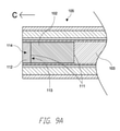
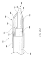
図2Aは、細長い本体1102及びハンドピース1104を具備する、上述の凝血塊排出システムにおいて利用され得る統合された凝血塊排出装置1100の実施形態の正面及び背面の斜視図を示す。細長い本体1102の長さは、幅又は直径よりも少なくとも約1.5倍長く、又は、幅又は直径よりも少なくとも約2倍長く、又は、少なくとも幅又は直径よりも約4倍長く、又は、少なくとも幅又は直径よりも約10倍長く、又は、少なくとも幅又は直径よりも20倍長く、又は、少なくとも幅又は直径よりも約30倍長く、又は、幅又は直径よりも少なくとも約50倍長く、又は、幅又は直径の50倍の長さとすることができる。細長い本体1102の長さは、変化してもよく、場合によっては、少なくとも約2cmの長さ、又は、少なくとも約4cmの長さ、又は、少なくとも約6cmの長さ、又は、少なくとも約8cmの長さ、又は、少なくとも約10cmの長さ、又は、少なくとも約15cmの長さ、又は、少なくとも約20cmの長さ、又は、少なくとも約25cmの長さ、又は、少なくとも約50cm、又は、50cmを超える長さとすることができる。細長い本体1102は、全長にわたって同じ外側断面寸法(例えば、直径)を有することができる。あるいは、断面直径は、細長い本体1102の長さに沿って変化してもよい。特定の実施形態では、細長い本体1102は管状の細長い本体となっており、管状の細長い本体の外径は約0.1~10mm、又は、約0.5mm~6mm、又は、約1mm~4mm、又は、約1.5mm~3mm、又は、約2mm~2.5m、又は、約2.1mmである。特定の実施形態では、細長い本体1102は、約2.1mmの外径(OD)及び約1.6mmの内径(ID)を有する14ゲージ針の直径を有する。
FIG. 2A shows front and back perspective views of embodiments of an
特定の実施形態では、明細書の他の箇所に記載されているように、細長い本体1102は、近位端1106及び遠位端1108を有することができる。用語「近位端」は、本明細書で使用される場合、細長い本体1102の、ユーザ(凝血塊排出処置において装置を操作する医師など)に近い端部を指し、用語「遠位端」は、本明細書では、細長い本体の、使用中に対象の内部標的組織に近づく端部を指す。細長い本体1102は、いくつかの例では、細長い本体1102の近位端に十分な力が加えられたときに、遠位端が押し出されて組織を通り抜けるのに十分な剛性をもつ構造である。そのようなものとして、特定の実施形態では、細長い本体1102は、少なくともある程度まで、曲げやすくも柔軟でもない。他の実施形態では、細長い本体1102は、可撓であり柔軟であり、細長い本体1102が組織の周りでねじれ、そして、曲がることを可能にする。
In certain embodiments, the
特定の実施形態では、遠位端1108は、開いた端部から視覚化、照明、灌注、及び/又は吸引を行うために、端部が開いている。細長い本体1102は、脳の組織を横切って、凝血塊のような目標となる標的に到達するよう使用することができる。この装置は、細長い本体の開放端を通して組織の視覚化を行い、図1に描かれたような別個のスクリーン上にこれらの画像を表示することができる。
In certain embodiments, the
特定の実施形態では、当該技術分野で知られているように、細長い本体の外側部分及び/又は内側のハイポチューブのような、凝血塊排出装置の任意の部分は、金属、ポリマー、又はその両方の組み合わせで作ることができ、管状、楕円形、長方形、又はこれらの全ての組み合わせを含むがこれに限定されない様々な構成をで作ることができる。細長い本体の遠位端の予め成形された形態は、2つの形状すなわち、固定された(一時的な)形状から所定の永久形状に切り替えることができる、「スマートマテリアル」とも呼ばれる、ニッケルチタン(NiTI)又は形状記憶ポリマー(SMP)のような形状記憶合金を使用して達成することができる。また、所望のたわみ特性を達成するために、金属、形状記憶金属、形状記憶ポリマー、又は従来のポリマーの任意の組み合わせを利用することができる。形状記憶ポリマーとしては、ポリウレタン又はポリスチレンが挙げられるが、これらに限定されない。このような記憶材料は、外部シャフトの向こうの空間に位置する望ましい治療領域にアクセスするために歪める必要があるデバイスを必要とする場合に有益である。特定の実施形態では、細長い本体は、可撓であるがねじれに耐える材料により作られ、それにより、使用中に細長い本体を撓めることができる。 In certain embodiments, as is known in the art, any part of the clot drainer, such as the outer and / or inner hypotube of an elongated body, may be metal, polymer, or both. It can be made of various configurations including, but not limited to, tubular, elliptical, rectangular, or all combinations thereof. The preformed form of the distal end of the elongated body can switch from two shapes, a fixed (temporary) shape to a given permanent shape, also known as a "smart material", nickel titanium (NiTI). ) Or shape memory alloys such as shape memory polymers (SMPs) can be used. Also, any combination of metal, shape memory metal, shape memory polymer, or conventional polymer can be utilized to achieve the desired deflection properties. Shape memory polymers include, but are not limited to, polyurethane or polystyrene. Such storage material is useful when a device that needs to be distorted to access a desirable therapeutic area located in the space beyond the external shaft is required. In certain embodiments, the elongated body is made of a flexible but twist-resistant material that allows the elongated body to flex during use.
図2Aに示すように、実施形態では、ハンドピース1104は、クラムシェル上部1112とクラムシェル底部1114とを接続するシーム1110を具備する丸い「クラムシェル」形状を有することができる。いくつかの実施形態では、クラムシェル上部1112及び底部1114は、2つの部品で製造され、次にシーム1110でくっ付けて一緒にされる。丸いクラムシェル形状は、使用している間ユーザが装置を保持するための快適で人間工学的なハンドルを提供する。特定の実施形態では、さらに詳細に後述するように、ハンドピースは、所望の画像を取り込むように構成されたボタン1116などの画像取り込み制御部を備えることができる。さらなる実施形態では、画像取り込み制御は、スイッチ、ダイヤル、又は他の適切な機構を具備することができる。ハンドピース1104は、細長い本体1102の一部を引き込み、又は伸ばす、引き込み制御1118をさらに具備することができる。引き込み制御1118については、図2B及び2C、及びそれに続く図を参照してより詳細に説明する。特定の実施形態では、ハンドピース1104はバヨネット式デザインとすることができる。
As shown in FIG. 2A, in embodiments, the
特定の実施形態では、制御部1116は、画像及び/又はビデオの取得を選択的に起動させることができる。従って、制御1116は、ビデオ録画の間、又はビデオ録画を停止している間に、選択的に、ビデオ録画を開始し、ビデオ録画を停止し、及び/又は静止画像をキャプチャするように構成することができる。実施形態では、これらの動作を、音声及び/又はタブレット上のボタンを介して開始させることができる。特定の実施形態では、補助的な、タブレット/電話/表示装置を滅菌ドレープバッグに入れておくことができる。
In certain embodiments, the
実施形態では、ハンドピース1104は、ここに記載されるような、又は、本明細書の他の箇所記載される滅菌生理食塩水のような、どのような流体供給源にでも接続するように構成されたルアー接続部1120を具備することができる。ルアー接続部1120は、細長い本体1102の全長に亘って延びる内腔と流体的に連通することができ、組織部位への流体又は薬剤の送出を可能にする。
In embodiments, the
ハンドピース1104と細長い本体1102との間の接合部に、ハンドピース1104を細長い本体1102に接続するハブ1122を含めることができる。いくつかの実施形態では、ハブ1122は取り外し可能であり、細長い本体をハンドピース1104から取り外すことができる。他の実施形態では、一体化されたアセンブリとするために、細長い本体は、ハブ1122を介してハンドピース1104に恒久的に取り付けられる。ハンドピース1104は、電気ケーブル(図2Aには図示せず)に取り付けるように構成されたひずみ軽減ノード1124をさらに備えることができる。ひずみ軽減ノード1124は、ハンドピース1104と電気的に通信することができる電気配線上のひずみを低減するのに役立つことができる。
The junction between the
いくつかの実施形態では、凝血塊排出装置1100は、一時的な使用のための統合されたアセンブリとして構成される。凝血塊排出装置1100は予め滅菌されていてもよく、従って、統合と前滅菌との組み合わせにより、パッケージから取り出してすぐに凝血塊排出装置1100を使用できるようになる。使用後、廃棄することができる。従って、ハンドピース1104、細長い本体1102、及び、ケーブルのような他の構成要素は、すべて単一のユニットとすることができる。1つの単一のユニットとは、上述の様々な部分が、ユーザによって分解されることを意図されていない単一の部品として一緒に取り付けられることがあることを意味する。いくつかの実施形態では、単一ユニットの様々な部分は、1つ以上の構成要素を壊すことなく分解することができない。いくつかの実施形態では、このセクション又は本明細書の他の部分に記載されているように、表示装置も単一のユニットの凝血塊排出装置の一部として組み込み、滅菌することができる。
In some embodiments, the
凝血塊の画像化に関して、方法には、細長い本体1102の遠位端を、標的組織(例えば、凝血塊及び/又は脳組織)に対する関係を見るための位置に置くステップと、標的組織を見るために凝血塊排出装置に統合された観察要素及び/又は画像化要素を用いるステップとが含まれる。関係を見るための位置とは、遠位端が、関心のある標的の5mm以内を含めて、40mm以内、例えば10mm以内に配置されることを意味する。経皮アクセスポイントから標的組織への直接線形前進を含む、便利なアプローチ方法を用いて、所望の標的組織に対応して凝血塊排出装置の遠位端の位置決めを行うことができる。凝血塊排出装置の遠位端について標的組織との関係を見るための位置決めを行った後、画像データを得るための照明要素及び視覚化センサ(本明細書の他の箇所に記載されている)を使用して標的を画像化して画像データを得る。本発明の方法に従って得られた画像データは、例えば、モニタ又は他の便利な媒体を表示手段として使用し、画像の形でユーザに出力される。特定の実施形態では、画像は静止画像とし、他の実施形態では、画像は動画とすることができる。
With respect to the imaging of the clot, the method involves placing the distal end of the
凝血塊部位へアクセスするために頭蓋骨の穿頭孔又は他の開口部を伴うシステムの実施形態では、トロカールとしてよく知られている内視鏡補助型マイクロ脳神経外科装置を、本明細書のこの章又は他の箇所に開示された装置及びるシステムの実施形態と組み合わせて既知の方法で使用することができる。本明細書に開示された凝血塊排出装置は、以下に記載されるようなトロカールの任意のチャネル内で使用することができる。トロカールは、穿頭孔を含む神経外科処置においてしばしば使用されるいくつかの装置の管理及び制御の補助のために使用される。そのような商業的デバイスの例には、Aesculap、B. Braun(ドイツ連邦共和国、メルズンゲン)のMINOP Trocars及びMedtronic Inc.(ミネソタ州、ミネアポリス)のChannel Trocarsが含まれるが、これらに限定されない。ほとんどの従来のトロカールは、3つ又は4つのチャネルを有する。例えば、3チャネルのトロカールは、遠位端及び近位ハンドルを有する細長い管、2つの小さなチャネル(灌注チャネル及びオーバーフローチャネル)、及び視覚化デバイス及び/又は治療デバイスを導入することが可能となる1つの大きなチャネルを有する。4チャネルのトロカールは、2つの小さなチャネル(灌注チャネル及びオーバーフローチャネル)及び2つのより大きなチャネル(スコープ又は超音波診断装置のような視覚化装置のためのもの)を有し、遠位端及び近位ハンドルを有する細長いチューブを有することがある。他の例では、4チャネルのトロカールにより、脳室フィステル形成術、生検、嚢胞、凝血塊及び他の障害物の除去のような神経外科処置が、視覚化チャネルに配置された内視鏡又は診断装置と同時に直接視覚化された状態で行うことができる。3チャネルのトロカールは、視覚化装置をまずワーキングチャネルに配置して治療領域を評価し、その後、治療装置を同じチャネルを通して導入して治療手順を実行することができるように、視覚化装置を取り除く必要がある。トロカールは、通常、金属製であるが、ポリマー製でもよく、100~400mmの任意の長さの可変部を有することができる。 In embodiments of systems involving a skull burr or other opening to access a clot site, an endoscopically assisted microneurosurgery device, commonly known as a trocar, is used in this chapter of the specification. Alternatively, it can be used in a known manner in combination with embodiments of the device and system disclosed elsewhere. The clot drainer disclosed herein can be used within any channel of the trocar as described below. Trocars are used to assist in the management and control of some devices often used in neurosurgical procedures, including burr holes. Examples of such commercial devices include Aesculap, B. et al. Includes, but is not limited to, MINOP Trocars from Braun (Melsungen, Germany) and Channel Trocars from Medtronic Inc. (Minneapolis, Minnesota). Most conventional trocars have three or four channels. For example, a three-channel trocar makes it possible to introduce an elongated tube with a distal end and a proximal handle, two small channels (irrigation and overflow channels), and a visualization and / or therapeutic device. Has two large channels. The 4-channel trocar has two small channels (irfusion channel and overflow channel) and two larger channels (for visualization devices such as scopes or ultrasound diagnostic devices), distal end and near. May have an elongated tube with a position handle. In another example, a 4-channel trocar allows neurosurgical procedures such as ventricular fistula plasty, biopsy, cyst, clot, and removal of other obstacles to be performed endoscopically or placed in the visualization channel. It can be performed in a directly visualized state at the same time as the diagnostic device. The 3-channel trocar removes the visualization device so that the visualization device can first be placed in the working channel to evaluate the treatment area and then the treatment device can be introduced through the same channel to perform the treatment procedure. There is a need. The trocar is usually made of metal, but may be made of polymer and can have a variable portion of any length of 100-400 mm.
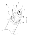
図2Bは、図2Aに示されている凝血塊排出装置1100の実施形態の垂直断面図を示す。図2Aと同様に、凝血塊排出装置1100は、画像取り込みトリガ1116、引き込み制御1118、ルアー1120、細長い本体1102、ハンドピース1104、及びハブ1122を含む。
FIG. 2B shows a vertical cross-sectional view of the embodiment of the
ここで図2Cを参照すると、いくつかの実施形態では、ハンドピース1104は、引き込み制御1118を含むことができる。引き込み制御1118は、図3Aの外側管状体1126を(詳細は後述する)ハイポチューブ1128に対して後退させるように機能し、ハイポチューブ1128が遠位端1108で外側管状体1126の前方開口部を越えて突き出ることが可能となる。
Now with reference to FIG. 2C, in some embodiments, the
図3Aは、図2A~図2Cの細長い本体の遠位端1108の実施形態の側面断面図を示し、図2A~図2Cには示されていない詳細を追加して示されている。細長い本体1102は、細長いチューブの形態とすることのできる外側管状体1126を具備する。外側管状体1126の寸法は変更可能であるが、好ましくは直径約3.7mmである。視覚化は、外側の管状体を通って同心円状に延びる内側のハイポチューブ1128によってもたらされる。この内側ハイポチューブ1128は、組織部位の画像をハンドピース1104に配置されたカメラに送信する役割を果たすことができ、又は、内側のハイポチューブ1128の遠位先端にカメラを配置することができる。内側のハイポチューブ1128はまた、標的組織を照射するために照明ファイバのような照明要素1134を有することもできる。いくつかの実施形態では、外側管状体1126は、内側ハイポチューブ1128を越えて前方にスライドするか、又は後退させて、内側ハイポチューブ1128を外側管状体1126を超えて突き出ることができる。図3Aに示すように、外側管状体1126が前方位置にスライドされると、内側ハイポチューブ1128内の視覚化要素(例えば、カメラ、レンズ、及び関連構成要素)は、概略的に図3Aに描かれているように、ハイポチューブ1128の内部の「トンネル」を通る視野3000を有することができる。そのような位置は、軟部組織を遠位光学部1136(レンズなど)から離すことができ、また遠位先端の組織に焦点が合うように十分な距離を確保することができる(図3A参照)。
FIG. 3A shows a side sectional view of an embodiment of the
特定の実施形態では、細長い本体1102は、横方向又は横方向で生じることがあるたわみを有することがある。ハイポチューブ1128の遠位端は、外側管状体1126から横方向に離れるように伸びることができる。たわみ又は距離の程度は、内側ハイポチューブ1128をさらに任意の方向に移動させることによって、必要に応じて移動させて調整することができる。特定の実施形態では、細長い本体1102の遠位端1108を回転させることで、遠位部分をさらに大きな空間内の領域にアクセスさせるために、ハンドピース1104を360度回転させることができる。遠位端1108は、患者の頭部内で上下に移動することができ、それによって遠位端1108を元の位置を越えて広範囲な空間へと曲げることができる。
In certain embodiments, the
いくつかの実施形態では、視覚化要素の遠位端は、内部組織部位の画像化を容易にするように構成された遠位レンズ1136を含むことができる。遠位レンズ1136又はその他のレンズは、製造中に欠陥及び不完全部を生じることがあり、その結果、画像に歪みをもたらすことがある。これらの歪みは、個々のレンズに固有なものであることがあり、従って、本明細書に開示された実施形態の場合、個々の凝血塊排出装置1100に固有なものである可能性がある。従って、画像品質を向上させるために、図2Aに示す装置1100は、独自のアルゴリズムの形態で自動光学補正を含むことができる。いくつかの実施形態では、アルゴリズムは、ハンドピース1104内のチップ又は他の適切な媒体に保存することができる。
In some embodiments, the distal end of the visualization element can include a
特定の実施形態では、自動光学補正は、凝血塊排出装置1100によって生成される画像品質を改善する役割を果たすことができる。アッベ数は、透明材料のVナンバー又はコンストリジェンス(constringence)としても知られ、屈折率に関連する材料の分散(波長による屈折率の変化)の尺度であり、Vの高い値は低分散(低い色収差)を示す。画質を最適化するためには色収差が低いことが望ましいが、低い色収差を達成しようとすると通常は製造コストが増加する。いくつかの実施形態では、凝血塊排出装置内の色収差は、臨床使用時に前述のソフトウェアアルゴリズムによって補正することができるので、製造コストの低減が可能となる。例えば、光学補正により、安価なレンズを有する装置からの視覚化を、欠陥の少ないはるかに高価なレンズを使用する視覚化装置の性能に匹敵する性能とすることができる。
In certain embodiments, automatic optical correction can serve to improve the image quality produced by the
特定の実施形態では、光学補正は、撮像画像を既知の定義パターンと比較し、個々の組織視覚化装置に固有の色収差及び画像歪みを補正するアルゴリズムを生成することによって生成することができる。いくつかの実施形態では、光学補正は、個々の組織視覚化装置について固有とすることができる。特定の実施形態では、一貫した初期光レベルを満足させるように、レンズの中心のX、Y位置、画像円のサイズ、及びLEDの固有の特性など、組織視覚化装置に関する追加情報を保存することができる。凝血塊排出装置の前述の特性及び本明細書の他の箇所に記載されている追加特性は、製造中に決定され、電気的に消去可能なプログラマブルリードオンリーメモリ(EEPROM)のようなコンピュータメモリに保存することができる。実施形態では、ハンドピース1104及び細長い本体1102の全体を一体化されたユニットとすることができる。特定の実施形態では、ハンドピース1104は、光ハイポチューブ1128の遠位レンズ1136を露出させるように細長い本体1102を後退させるように構成された引き込み制御1118をさらに備える。いくつかの実施形態では、ハンドピース1104は、内腔を介して内部組織部位に流体を導くように構成されたルアー1120をさらに備えることができる。
In certain embodiments, optical correction can be generated by comparing the captured image with a known definition pattern and generating an algorithm that corrects for chromatic aberration and image distortion inherent in the individual tissue visualization device. In some embodiments, the optical correction can be specific for an individual tissue visualization device. In certain embodiments, storing additional information about the tissue visualization device, such as the X and Y positions of the center of the lens, the size of the image circle, and the unique characteristics of the LED, to satisfy a consistent initial light level. Can be done. The aforementioned properties of the clot drainer and the additional properties described elsewhere herein are in computer memory such as programmable read-only memory (EEPROM) that is determined during manufacture and is electrically erasable. Can be saved. In the embodiment, the
実施形態では、製造現場でアルゴリズムを生成するために、遠位光学1136は、既知の定義パターンに焦点を合わせる。コンピュータは、キャプチャされたイメージを既知のパターンと比較し、キャプチャされたイメージを真の定義パターンに復元するアルゴリズムを作成することができる。上述のように、そのアルゴリズムはハンドピース1104内のチップに保存することができる。
In an embodiment, the
ハンドピース1104が、図1に関連して先に説明したように臨床現場で表示装置6に接続されているとき、光学システムの収差が除去されるように、キャプチャされた画像を修正するためのアルゴリズムが表示装置6の基準として機能する。個々の凝血塊排出装置1100は固有の収差を有するので、各ハンドピース1104は、そのシステムを修正するように設計された固有のアルゴリズムを持つ。
To correct the captured image so that when the
特定の実施形態では、細長い本体1102は、アクセス装置の内部通路を通って摺動可能に移動するような、又は追加のアクセス装置を使用せずに組織を直接移動するような寸法にすることができる。いくつかの実施形態では、細長い本体1102は、その幅の1.5倍以上、例えばその幅の2倍又はそれ以上の長さを有することができる、その幅よりも5倍又は10倍又はそれ以上幅、その幅よりも30倍長い、又はそれより長くすることもできる。装置の少なくとも遠位端は、10mm以下、例えば8mm以下、及び7mm以下を含む最長断面寸法を有することができ、特定の実施形態では最も長い断面寸法は、5~10mm、例えば6~9mm、6~8mmを含む。
In certain embodiments, the
いくつかの実施形態では、ハイポチューブ1128は、外側管状体1126の内径側に押し付けることができる。例えば、外側管状体1126は、細長い本体1102の内径に対してハイポチューブ1128の外径を押し付けるように、外側管状体1126又はハイポチューブ1128のいずれかにディンプルを具備することができる。
In some embodiments, the
特定の実施形態では、外側管状体1126は、伸縮自在ではなく、外側管状体1126及び内側ハイポチューブ1128は、一定の長さを有する。例えば、内側ハイポチューブ1128は、外側管状体1126と同じ長さであってもよく、又は、内側ハイポチューブ1128が外側管状体1126の内側にオフセットされるように、より短くてもよい。あるいは、内側のハイポチューブ1128は、外側の管状体1126の側面に押し付けられるようにしてもよい。
In certain embodiments, the outer
実施形態では、細長い本体1102の遠位端1108は、機械的手段によりハイポチューブ1128の視野方向を(約5~6度のように)変更を可能にするために、撓ませた先端を具備することができる。いくつかの実施形態では、視野の方向は、少なくとも約3度、又は少なくとも約6度、又は少なくとも約12度、又は少なくとも約15度、又は少なくとも約20度、又は少なくとも約30度、又は少なくとも約45度、又は45度を超えてハイポチューブ1128の中心の長軸からずらすことができる。広角視野は、レンズを用いて、又は遠位端が軸から外れた場合に光ファイバを回転させることによって達成することができる。
In embodiments, the
いくつかの実施形態では、内側ハイポチューブ1128を取り囲むのは、図3Aに示すように、凝血塊を除去するため及び/又は遠位レンズを洗浄するための灌注を行うため、及び/又は凝血塊を壊すために使用される内腔1138である。いくつかの実施形態では、内腔1138に沿って、又は外側管状体の周りの外側スリーブを介して、灌注を行う又は代替的に灌注を行うことができる。あるいは、灌注は、外側管状体1102内の別個のチャネルに沿って行うこともできる。特定の実施形態では、装置は、遠位レンズ1136を洗浄するために、明細書の他の箇所に記載された灌注モードのうちのいずれかを使用することができる。
In some embodiments, the
特定の実施形態では、凝血塊排出装置には、内部標的組織部位及び/又は視覚化センサのレンズのような装置の構成要素を洗浄するように構成された灌注器及び吸引器をさらに含めることができる。このように、細長い本体1102には、本明細書のこの箇所又は本明細書の他の箇所で要約されるような、例えば、様々な異なる機能を実行するために、少なくともデバイスの実質的な長さ方向に延びる1つ以上の内腔をさらに含めることができる。細長い本体1102の遠位端の標的組織部位を(例えば、その部位から切除された組織を除去するために)フラッシュする(すなわち、洗浄する)ことが望ましい特定の実施形態では、細長い本体1102には、灌注内腔及び吸引内腔の両方を含めることができる。従って、凝血塊排出装置は、細長い本体を軸方向に貫通する灌注内腔を備えることができる。使用中、灌注内腔は、デバイスの近位端の流体源(例えば、生理食塩水などの生理学的に許容される流体)に動作可能に接続することができ、流体源は、流体が灌注内腔に沿って遠位端部へと移送されるように、例えば0psiから60psiの範囲の圧力で加圧することができる。灌注内腔の寸法は変更可能であるが、特定の実施形態では、灌注内腔の最も長い断面寸法は0.5mmから5mm、例えば、0.5mmから3mm、又は0.5mmから1.5mmなど、の範囲とする。
In certain embodiments, the clot drainer may further include an infusion device and an aspirator configured to clean the internal target tissue site and / or the components of the device such as the lens of the visualization sensor. can. Thus, the
使用中、吸引内腔(例えば、内腔1138)は、装置の近位端の負圧源(例えば、真空源)に動作可能に接続することができる。例えば、吸引を行う手段には、真空ポンプ、病院の壁供給源、手動注射器、及び/又は足で操作する装置を含めることができる。吸引内腔の寸法は変えることができるが、特定の実施形態では、吸引内腔の最も長い断面寸法は、1mmから7mm、例えば、1mmから5mmを含む1mmから6mmなど、の範囲である。いくつかの実施形態では、アスピレーターは、細長い本体の遠位端の断面積の33%以上、例えば66%以上を含む50%以上など、の断面積を有するポートを含む。壁吸引を使用する代わりに、装置は、助手が操作する大きな注射器を代わりに使用することができる。いくつかの実施形態では、バッテリ駆動の真空ポンプを使用することができ、及び/又は廃棄チャンバに組み込まれた足で操作するポンプを用いてもよい。 During use, the suction lumen (eg, lumen 1138) can be operably connected to a negative pressure source (eg, vacuum source) at the proximal end of the device. For example, means of suction can include vacuum pumps, hospital wall sources, manual syringes, and / or foot-operated devices. The dimensions of the suction lumen can be varied, but in certain embodiments, the longest cross-sectional dimensions of the suction lumen range from 1 mm to 7 mm, eg, 1 mm to 6 mm, including 1 mm to 5 mm. In some embodiments, the ejector comprises a port having a cross-sectional area of 33% or more, for example 50% or more including 66% or more, of the distal end cross-sectional area of the elongated body. Instead of using wall suction, the device can use a large syringe operated by an assistant instead. In some embodiments, battery-powered vacuum pumps can be used and / or foot-operated pumps built into the disposal chamber may be used.
いくつかの例では、負圧源は、負圧、例えば300から600mmHgの範囲の負圧、例えば550mmHgで、遠位端の標的組織部位から吸引内腔内に流体及び/又は組織を引き込むように構成する。流体及び/又は組織が組織部位から除去され、吸引内腔に沿って、そして近位端の外へ、例えば廃棄物リザーバ内に搬送されるようにする。特定の実施形態では、灌注内腔及び吸引内腔は別個の内腔であってもよく、他の実施形態では、灌注内腔及び吸引機能は単一内腔で達成することもできる。 In some examples, the negative pressure source is a negative pressure, eg, a negative pressure in the range of 300 to 600 mmHg, eg 550 mmHg, to draw fluid and / or tissue from the distal target tissue site into the suction lumen. Configure. The fluid and / or tissue is removed from the tissue site and transported along the suction lumen and out of the proximal end, eg, into a waste reservoir. In certain embodiments, the irrigation and suction lumens may be separate lumens, and in other embodiments, the irrigation and suction functions can also be achieved with a single lumen.
特定の実施形態では、吸引は、上述の壁吸引を超えて増加されるべきである。例えば、壁吸引は、凝血塊を装置のチャネル及びチューブを通して吸引するが、凝血塊を装置に引き入れるために、又は詰まったチャネル/チューブに対して吸引を増大させるために、もっと強い手動吸引又はポンプ駆動吸引を使用することができる。特定の実施形態では、灌注及び吸引のために様々な制御装置を使用することができる。例えば、制御部は、ハンドピース1104、コード、タブレット(物理的ボタン、ソフトボタン、音声起動)及び/又は足ペダルとして配置することができる。特定の実施形態では、血圧測定用カフを使用して吸引を行うことができる。
In certain embodiments, suction should be increased beyond the wall suction described above. For example, wall suction sucks the clot through the channel and tube of the device, but a stronger manual suction or pump to draw the clot into the device or to increase suction for a clogged channel / tube. Driven suction can be used. In certain embodiments, various controls can be used for irrigation and suction. For example, the control unit can be arranged as a
しかしながら、凝血塊の吸引中に起こり得る共通の問題は、凝血塊が内腔1138内に留まり、それによってさらなる灌注及び吸引を阻止/制限してしまうことである。これらの潜在的な問題に対処するために、いくつかの実施形態では、図3Bに示すように、視覚化要素(視覚化センサ及びレンズなど)を含む内部ハイポチューブ1128を振動させて、内腔1138に留まっている可能性のある凝血塊を壊し除去することができる。図1で上記したように、及び/又は、図3Bで以下でさらに詳細に示すように、ハンドピース1104は、内側ハイポチューブ1128を振動させることができる、振動アクチュエータ1140及び/又は振動プレート又はモータ1142をさらに備えることができる。実施形態では、内部ハイポチューブ1128は、振動中の損傷を防止するために、振動に耐えるように構成することができる。当業者には理解されるように、本明細書の本セクション又は本明細書の他の箇所に記載された任意のポート(吸引ポート1122など)は、吸引、灌注、又はその両方に使用されてもよい。図3Bに示すように、外側管状体1126は、視覚化装置と共に内側ハイポチューブ1128の遠位端部を越えて突き出すことができ、引き込んで、視覚化装置を、外側管状体1126を越えて効果的に突き出すことができる。
However, a common problem that can occur during aspiration of a clot is that the clot remains within
いくつかの実施形態では、図3Cに図示し説明したように、外側管状体1126及び/又は内側ハイポチューブ1128は、凝血塊の除去をさらに補助するために互いに相対的に回転可能とすることができる。ハンドピース1104には、外側管状体1126を回転させる一体化された手段を含めることができる。これらの手段には、ユーザが手動で回転させることができる、内部モータ及び/又は外部サムホイール1144を含めることができる。図3Dは、図3Cの矢印3D-3Dによって示される方向から見た、細長い本体1102に沿った断面図であり、内側のハイポチューブ1128に対する相対的な外側の管状本体1126の回転を概略的に示している。内側のハイポチューブ1128は、外側管状体1126が回転するときに、外側管状体1126内のランダムな位置にとどまることができ、それにより、内腔内に留置された凝血塊を除去するのを補助するスクレーパとして作用する。外側管状体1126は、回転中に体組織を保護するために外面保護シースを通して挿入することができる。いくつかの実施形態では、内側のハイポチューブ1128は、外側の管状体1126に加えて、又はその代わりに、回転可能な構成とすることができる。
In some embodiments, as illustrated and illustrated in FIG. 3C, the outer
特定の実施形態では、図3Eに示すように、凝血塊排出装置1100は、灌注のための第2のポート1146をさらに備えることができる。外側管状体1126を外径とスリーブ1148の内径との間に灌注のための経路を作るために、上述のように、外側管状体1126を覆う外側スリーブ1148に、さらに灌注ポート1146を接続することができる。外側スリーブ1148は、剛性又は半剛性のチューブで構成されてもよい。実施形態では、外側管状体1126は、必ずしも著しい量の流体を手術部位に導入することなく、凝血塊閉塞を除去するのを助けるために穿孔することができる。穿孔の間隔は、外側管状体1126の遠位端寄りでは多くの穿孔が存在し近位端寄りでは穿孔が少なくなるよう、変化させることができる。さらに、凝血塊排出装置1100の遠位端は、図3Eに示すような形状にして、レンズをきれいにするため、及び/又は凝血塊に外部灌注を行うために流体を光学要素に向けることができる。外側スリーブ1148は、凝血塊排出装置1100の遠位先端を越えて突き出すことができ、さらに滑らかにするために先細又は傾斜を持たせた遠位端を備えることができる。さらに、本明細書の他の部分に記載されているように、灌注要素を備えた外側スリーブ1148の遠位端は、引き入れることも、突き出すこともできる。灌注要素を備えた外側スリーブ1148の遠位端は、突き出したとき、脳組織の破壊を最小限にする軟組織へのイントロデューサとして機能することができる。灌注要素を有する外側スリーブ1148の遠位端を後退させることで、外側管状体1126の端部を清掃して吸引内腔を開くことができる。吸引内腔内に留まっている可能性のある凝血塊を壊す手助けをする機能を用いることで、ユーザが途中で凝血塊を除去するために装置を取り外し、再び装置を導入し、標的組織を再配置する必要性をなくすことができる。
In certain embodiments, as shown in FIG. 3E, the
上述のように、特定の実施形態では、細長い本体1102は、例えば、様々な異なる機能を実行するために、少なくともデバイスの実質的な長さまで伸びる1つ以上の注入内腔1138をさらに含むことができる。細長い本体1102の遠位端1108でその位置の標的組織を洗い流す(すなわち、洗浄する)ことが望ましく、余分な流体を除去することが望ましい特定の実施形態では、細長い本体1102は、灌注内腔及び吸引内腔の両方を含むことができる。使用中、灌注内腔は、装置の近位端で流体源(例えば、生理食塩水のような生理学的に許容される流体)に動作可能なように接続することができ、流体が灌注内腔に沿って遠位端へと運ばれるようにするために、流体源は加圧された状態、即ち0~500mmHgの範囲の圧力が加わった状態で、流体を内腔に導入するよう構成される。
As mentioned above, in certain embodiments, the
灌注内腔の寸法は変えることができるが、特定の実施形態では、灌注内腔の最も長い断面寸法は1~3mmの範囲である。使用中、吸引内腔は、装置の近位端の負圧源(例えば、真空源)に動作可能に接続され、負圧源は、遠位端の組織位置から負圧状態、例えば約50~600mmHgの範囲の圧力が加わった状態で、流体を灌注内腔に引き込むように構成され、流体は、灌注内腔に沿って近位端を出て、例えば廃棄物リザーバ内へと運ばれる。吸引内腔の寸法は変えることができるが、特定の実施形態では、吸引内腔の最も長い断面寸法は、約1~10mm、約1~4mm、約1~3mm、又は1mm未満の範囲である。あるいは、灌注及び/又は吸引を行うことができる単一の内腔が設けることもできる。実施形態では、製品パッケージには、流体の流れを制御する手段として単一のポート停止コックを含めることができる。特定の実施形態では、ストップコック又は適切なバルブを装置に直接組み込むことができる。さらなる実施形態では、2つのポート及び2つのストップコック、3つのポート及び3つのストップコックなどのような、2つ以上のポート又はストップコックが使用されてもよい。いくつかの実施形態では、チューブを接続及び再接続せずに、臨床医が注入と吸引との間を「トグルスイッチで切り替える」又は第1及び第2の流体の注入を切り替えることができるように三方ストップコックを設けることができる。 The dimensions of the irrigation lumen can be varied, but in certain embodiments, the longest cross-sectional dimensions of the irrigation lumen range from 1 to 3 mm. During use, the suction cavity is operably connected to a negative pressure source (eg, a vacuum source) at the proximal end of the device, and the negative pressure source is in a negative pressure state from the tissue location at the distal end, eg about 50-. It is configured to draw the fluid into the irrigation cavity under pressure in the range of 600 mmHg, and the fluid is carried along the irrigation cavity from the proximal end, eg, into a waste reservoir. The dimensions of the suction lumen can be varied, but in certain embodiments, the longest cross-sectional dimensions of the suction lumen range from about 1-10 mm, about 1-4 mm, about 1-3 mm, or less than 1 mm. .. Alternatively, a single lumen capable of irrigation and / or aspiration can be provided. In embodiments, the product package can include a single port stop cock as a means of controlling fluid flow. In certain embodiments, a stopcock or suitable valve can be incorporated directly into the device. In a further embodiment, two or more ports or stopcocks may be used, such as two ports and two stopcocks, three ports and three stopcocks, and the like. In some embodiments, the clinician can "toggle switch" between injection and aspiration or switch between injections of the first and second fluids without connecting and reconnecting the tubes. A three-way stop cock can be provided.
図3Aに戻って、細長い本体1102は、鋭利な先端を除去した14ゲージ針のような皮下注射針に類似する外側管状体1126を含むことができる。しかし、特定の実施形態(図示せず)では、細長い本体1102の遠位端は、尖った先端を備えることができる。視覚化要素は、外側管状体1126を同軸に通って延びる、内側ハイポチューブ1128の形状とすることができる。ハイポチューブ1128は、このセクション及び本明細書の他の箇所に記載されているような視覚化センサに組織部位の画像を送信する役割を果たすことができる。いくつかの実施形態では、ハイポチューブ1128の遠位先端は、視覚化センサを具備することができる。
Returning to FIG. 3A, the
特定の実施形態では、図3Fに示すように、視覚化センサ1150、又は、ここに記載され又は本明細書の他の箇所に記載された任意の他のタイプのセンサ(グルコースセンサなど)は、図に示すように配置することができる。例えば、2つのセンサ1150は、ハイポチューブ1128の細長い本体又は他の視覚化装置本体の、後方に配置することができ、前方及び後方(左側パネル)に面し、側方に面し(すなわち、細長い本体の長手方向軸に垂直に)、そして前向きに(中間パネル)、及び/又は正面及び側面(右側パネル)を向くように角度付けされ、いくつかの例では画像が統合される。例えば、右側のパネルに示された各センサ1150からの画像は、より広い視野を有するより大きな画像を形成するために組み合わせて一緒にすることができる。本明細書の他の箇所に記載されているように、ハイポチューブ1128は、回転、振動、及び/又は並進運動を可能とすることができる。
In certain embodiments, as shown in FIG. 3F, the
関心のある視覚化センサは、例えば、集積回路に結合され、光を電子に変換する感光性要素のアレイのような、感光性構成要素を含むものである。集積回路は、感光性アレイからの信号を取得して統合し、画像データを出力するように構成することができ、画像データは、データを受信して、ユーザに表示するように構成された体外ディスプレイに伝達することができる。これらの実施形態の視覚化センサは、集積回路イメージセンサとして見ることができる。 Visualization sensors of interest include photosensitive components, such as, for example, an array of photosensitive elements that are coupled to an integrated circuit and convert light into electrons. The integrated circuit can be configured to capture and integrate signals from the photosensitive array and output image data, which is extracorporeally configured to receive the data and display it to the user. It can be transmitted to the display. The visualization sensors of these embodiments can be viewed as integrated circuit image sensors.
これらのセンサの集積回路コンポーネントは、画像信号処理、メモリ、及び視覚化センサから体外にデータを送信するためのデータ送信回路などを含むが、これらに限定されない様々な別々の機能を含むことができる。小型視覚化センサは、感光性構成要素に対して像を結像するような、感光性構成要素に対する相対位置に配置した以上のレンズからなるレンズ構成要素をさらに含むことができる。必要に応じて、1つ以上のレンズをハウジング内に収容することができる。対象となる特定の種類の小型視覚化センサには、相補型金属酸化物半導体(CMOS)センサ及び電荷結合素子(CCD)センサが含まれる。センサは、円形、正方形、長方形などを含む、任意の使いやすい構成を有することができる。対象となる視覚化センサは、特定の実施形態に従い変化する最も長い断面寸法を有することができ、場合によっては、最大断面寸法(例えば、直径)は、例えば、3.0mm以下を含んで6.0mm以下などのような、10.0mm以下となる。 The integrated circuit components of these sensors can include a variety of separate functions, including, but not limited to, image signal processing, memory, and data transmission circuits for transmitting data out of the body from visualization sensors. .. The small visualization sensor may further include a lens component consisting of more lenses arranged relative to the photosensitive component, such as forming an image on the photosensitive component. If desired, one or more lenses can be housed in the housing. Certain types of small visualization sensors of interest include complementary metal oxide semiconductor (CMOS) sensors and charge-coupled device (CCD) sensors. The sensor can have any easy-to-use configuration, including circular, square, rectangular, and the like. The visualization sensor of interest may have the longest cross-sectional dimension that varies according to a particular embodiment, and in some cases the maximum cross-sectional dimension (eg, diameter) may include, for example, 3.0 mm or less. It will be 10.0 mm or less, such as 0 mm or less.
対象となる視覚化センサは、前面照明センサ又は背面照明センサのいずれかであってもよく、本発明の装置のハンドピース内の細長い本体の近位端に組み込むのに十分な機能を維持する一方、十分に小さな寸法を有する。これらのセンサの特徴は、以下の、すなわち、米国特許第7,388,242号、7,368,772号、7,355,228号、7,345,330号、7,344,910号、7,268,335号、7,209,601号、7,196,314号、7,193,198号、7,161,130号、及び、7,154,137号のうちの1つ以上の米国特許にさらに記載されており、これらの開示は、その全体が参照により本明細書に組み込まれるものとする。 The visualization sensor of interest may be either a front lighting sensor or a rear lighting sensor, while maintaining sufficient functionality to be incorporated into the proximal end of the elongated body within the handpiece of the device of the invention. , Has small enough dimensions. The features of these sensors are as follows: US Pat. Nos. 7,388,242, 7,368,772, 7,355,228, 7,345,330, 7,344,910, One or more of 7,268,335, 7,209,601, 7,196,314, 7,193,198, 7,161,130, and 7,154,137. Further described in US patents, these disclosures are incorporated herein by reference in their entirety.
細長い本体の遠位端は、要求に応じて、正面視及び/又は側面視用に構成することができる。さらに他の実施形態では、細長い本体は、前面及び側面の両方から画像データを提供するように構成することができ、例えば、導波路の遠位端からの主要な視野軸は、以下に詳述するように、約2度又は5度又は細長い本体の長手方向軸に対して10度又は15度又はそれ以上の角度で伸びる。 The distal end of the elongated body can be configured for frontal and / or lateral vision, if desired. In yet another embodiment, the elongated body can be configured to provide image data from both front and side surfaces, for example, the major visual field axes from the distal end of the waveguide are detailed below. As such, it extends at an angle of about 2 or 5 degrees or 10 degrees or 15 degrees or more with respect to the longitudinal axis of the elongated body.
特定の装置の実施形態に応じて、上述のように、細長い本体は、その長さに沿って少なくとも部分的に延びる1つ以上の内腔を含むことも含まないこともできる。内腔が存在する場合、内腔は、以下に詳述するように、直径を変化させることができ、灌注、吸引、(例えば、電線のような導電性部材の)電気的絶縁、機械的ガイドなどの様々な異なる目的のために使用することができる。内腔が存在する場合、そのような内腔は、1.0~4.0mmを含んで、例えば1.0~4.5mmのような、0.5~5.0mmの範囲の最も長い断面を有することができる。内腔は、円、四角、矩形、三角形、半円形、台形、不規則な形などを含むがこれに限定されない任意の使いやすい断面形状とすることができる。これらの内腔は、以下に詳述するように、灌注及び/又は吸引内腔を含む様々な異なる機能を提供することができる。 Depending on the embodiment of the particular device, as described above, the elongated body may or may not include one or more lumens that extend at least partially along its length. If a lumen is present, the lumen can be varied in diameter, irrigation, suction, electrical insulation (eg, for conductive members such as wires), mechanical guides, as detailed below. It can be used for various different purposes such as. If lumens are present, such lumens include the longest cross section in the range of 0.5-5.0 mm, including 1.0-4.0 mm, eg 1.0-4.5 mm. Can have. The lumen can be any easy-to-use cross-sectional shape including, but not limited to, circles, squares, rectangles, triangles, semicircles, trapezoids, irregular shapes, and the like. These lumens can provide a variety of different functions, including irrigation and / or suction lumens, as detailed below.
特定の実施形態では、図2~図3Eに関連して上述したように、凝血塊排出装置は、標的組織の位置を、上述した視覚化センサによりその位置を視認することができるように、照明するよう構成された1つ以上の照明要素を含むことができる。細長い本体の遠位端に配置することができ、又は細長い本体の遠位端に光を運ぶことができるような寸法とすることができさえすれば、様々な異なるタイプの光源を照明要素として使用することができる。光源は、所定の構成要素(例えば、細長い本体)の構造を著しく改変することなく構成要素の残りの部分から光源要素を除去することができないような、構成要素に対する配置となるように、構成要素と一体化されてもよい。このように、これらの実施形態の一体型照明要素は、構成要素の残りの部分から容易に取り外すことはできず、この照明要素及び残りの構成要素が相互に関連して全体を形成する。光源は、望ましい波長範囲の光を放射するように構成された発光ダイオード、又は、例えば、ハンドピース内の細長い本体の近位端の位置のような細長い本体の遠位端とは異なる位置から、細長い本体の遠位端へ望ましい波長範囲の光を伝達するように構成された光伝達要素、例えば、光ファイバとすることができる。 In certain embodiments, as described above in connection with FIGS. 2-3E, the clot drainer is illuminated so that the location of the target tissue can be visually recognized by the visualization sensor described above. It can include one or more lighting elements configured to do so. Various different types of light sources can be used as lighting elements as long as they can be placed at the distal end of the elongated body or sized to carry light to the distal end of the elongated body. can do. The light source is arranged so that the light source element cannot be removed from the rest of the component without significantly modifying the structure of the component (eg, the elongated body). May be integrated with. As such, the integrated luminaires of these embodiments cannot be easily removed from the rest of the components, and the luminaires and the rest of the components are interrelated to form the whole. The light source may be a light emitting diode configured to emit light in the desired wavelength range, or from a position different from the distal end of the elongated body, such as the position of the proximal end of the elongated body within the handpiece. It can be a light transfer element configured to transmit light in a desired wavelength range to the distal end of the elongated body, eg, an optical fiber.
特定の実施形態では、当業者に知られているように、画像化用カメラは、超音波と組み合わせて凝血塊排出装置の遠位端に設けることができる。そのような電子撮像カメラは、発光ダイオード(LAD)によって提供される発光源、又は外部から光ファイバを介して供給される発光源を有することができる。動作原理は内視鏡と同一であるが、この場合、カメラは超音波装置と共に単一の装置に組み込まれる。このような適切なカメラの例としては、MediGus.Ltd、イスラエル国、オメル;OmniVision、カリフォルニア州、サンタクララ;Clear Image Technology、オハイオ州、エリリア、の装置が挙げられるが、これに限定されない。更なる詳細は、2012年9月7日に出願された「患者の頭部から凝血塊及び組織を除去するための方法及び装置」と題する米国特許出願公開番号第2012/0330196A1号に記載されており、参照によりその全体が本明細書に組み込まれる。 In certain embodiments, as known to those of skill in the art, the imaging camera can be provided at the distal end of the clot drainer in combination with ultrasound. Such an electronic imaging camera can have a light emitting source provided by a light emitting diode (LAD) or a light emitting source supplied from the outside via an optical fiber. The principle of operation is the same as that of an endoscope, but in this case the camera is integrated into a single device together with an ultrasonic device. An example of such a suitable camera is MediGus. Ltd, Israel, Omer; OmniVision, California, Santa Clara; Clear Image Technology, Ohio, Elyria, but not limited to. Further details are set forth in U.S. Patent Application Publication No. 2012/0330196A1 entitled "Methods and Devices for Removing Clots and Tissues from the Patient's Head" filed September 7, 2012. And is incorporated herein by reference in its entirety.
視覚化センサの場合と同様に、光源には、細長い本体を通って、例えば、体外制御装置のような、身体の外部から電力を供給し制御をおこなう、例えば、ワイヤ又は光ファイバ又はそれらの束のような、伝達要素を含めることができる。 As with visualization sensors, the light source is powered and controlled from outside the body, eg, an extracorporeal control device, through an elongated body, eg, a wire or optical fiber or a bundle thereof. Can include transmission elements such as.
必要に応じて、光源は、標的組織部位へ均一な照明を行うために拡散要素を含むことができる。光源からの光が通過して拡散する半透明のカバー又は層(使い勝手の良い半透明材料で製造される)を含むが、これに限定されない使い勝手の良い拡散要素を使用することができる。システムが2つ以上の照明要素を含む本発明の実施形態では、照明要素は同じ波長の光を放射することができ、又は、照明要素はスペクトル的に異なる光源とすることもでき、「スペクトル的に異なる」とは、光源が白色光及び赤外光のような実質的に重複しない波長の光を放射することを意味する。特定の実施形態では、米国特許出願公開番号US2010/0121139A1及びUS2010/0121142A1(その全開示内容は参照により本明細書に組み込まれる)に記載された照明の構成が、この装置内に存在する。 If desired, the light source can include a diffusing element to provide uniform illumination to the target tissue site. Easy-to-use diffusing elements can be used, including, but not limited to, a semi-transparent cover or layer (manufactured from a convenient translucent material) through which light from a light source passes and diffuses. In embodiments of the invention where the system comprises two or more illuminating elements, the illuminating elements can emit light of the same wavelength, or the illuminating elements can be spectrally different light sources, "spectral. "Different" means that the light source emits light of substantially non-overlapping wavelengths, such as white light and infrared light. In certain embodiments, the lighting configurations described in US Patent Application Publication Nos. US2010 / 0121139A1 and US2010 / 0121142A1 (all disclosures thereof are incorporated herein by reference) are present within the apparatus.
いくつかの実施形態では、ここに記載した実施形態の装置は、視覚化要素に対して平行に移動する視覚化要素を取り囲む管状体のように、装置の遠位端要素を直線的に平行移動させる線形機械アクチュエータを含むことができる。「直線的に平行移動する」とは、要素を実質的に直線的な経路に沿って移動させることを意味する。ここで使用される場合、用語「線形」はまた、非直線(すなわち、湾曲した)経路における動きを包含する。 In some embodiments, the apparatus of the embodiment described herein translates linearly through the distal end element of the device, such as a tubular body surrounding the visualization element that translates parallel to the visualization element. It can include a linear mechanical actuator to make it. "Translating linearly" means moving an element along a substantially linear path. As used herein, the term "linear" also includes movement in a non-linear (ie, curved) path.
いくつかの実施形態では、細長い本体の遠位端及び/又は視覚化要素の遠位端に操縦可能性をもたらす統合された関節運動機構も、装置内に存在する。「操縦可能性」とは、処置を施している間に、例えば、装置の近位端に配置された制御装置を使用することによって、視覚化要素、組織変更器及び/又は細長い本体の遠位端を望み通りに操縦又は方向合わせを行う能力を意味する。これらの実施形態では、装置は、近位端制御によって望ましい遠位端構成要素を望み通りに操作可能にする操縦可能機構(又は細長い本体の遠位端に配置された1つ以上の要素)を含む。このように、本明細書で使用される「操縦可能性」という用語は、主視軸を最初の軸方向に対して相対的に左、右、上又は下に向けさせるなど、望ましい方法で方向を変えることのできるような、ユーザにステアリング機能を提供する機構を指す。 In some embodiments, there is also an integrated range of motion mechanism within the device that provides maneuverability to the distal end of the elongated body and / or the distal end of the visualization element. "Maneuverability" means the distal part of a visualization element, tissue changer and / or elongated body, for example by using a control device located at the proximal end of the device during the procedure. It means the ability to steer or orient the edge as desired. In these embodiments, the device provides a maneuverable mechanism (or one or more elements located at the distal end of the elongated body) that allows the desired distal end component to be manipulated as desired by proximal end control. include. Thus, the term "maneuverability" as used herein is directed in a preferred manner, such as directing the primary axis to the left, right, up or down relative to the initial axial direction. Refers to a mechanism that provides the user with a steering function that can be changed.
ステアリング機能は、様々な機構によって提供することができる。適切な機構の例には、形状記憶材料、音楽ワイヤなどの適切な材料で作製された1つ以上の軸方向に移動可能な引っ張り用又は押し込み用ワイヤ、又はチューブ、又はプレート、又はメッシュ、又はこれらの組み合わせが含まれるが、これらに限定されない。例えば、1つの能動的な偏向機構には、遠位セグメント内の外側管状体1126の第1の側に沿って軸方向に隔てた複数の横方向スロットを設けることが含まれる。遠位セグメント内の外側管状体1126の第1の側とは反対側(すなわち180°)の第2の側は、軸方向に非圧縮性の支柱として機能し、第1の側は軸方向に圧縮されて、第1の側の方向に側方に溝をつける。曲がりを引き起こし又は除去するための、第2の側に対する第1の側の軸方向圧縮(又は伸長)は、軸方向に移動可能な制御ワイヤによって達成することができる。制御ワイヤの遠位端は、遠位セグメント1108内の外側管状体1126に、好ましくは遠位セグメントの遠位端に固定することができる。制御ワイヤは、外側管状体1126の全長に亘って近位のたわみ制御部まで延びている。制御ワイヤを近位に引っ込めるための制御装置の操作は、横方向スロットをつぶし、第1の側部の軸方向長さを第2の側部に対して短くし、それによって遠位セグメントを偏向させる。
The steering function can be provided by various mechanisms. Examples of suitable mechanisms include one or more axially movable pulling or pushing wires, or tubes, or plates, or meshes, made of suitable materials such as shape memory materials, music wires, or the like. Combinations of these are included, but not limited to. For example, one active deflection mechanism comprises providing a plurality of lateral slots axially spaced along a first side of the outer
いくつかの例では、細長い本体の遠位端には、以下に詳述するように、操作ハンドルのかなりの部分が固定位置に維持されたときに、その長手方向軸の周りに独立して回転させることができる別個の追加機能が設けられている。 In some examples, the distal end of the elongated body rotates independently around its longitudinal axis when a significant portion of the operating handle is held in place, as detailed below. There is a separate additional feature that can be done.
本発明の遠位一次視野軸関節部の範囲は、一次視野軸から少なくとも約5、10、25、又は35度以上で変化させることができる。視覚化要素は、例えば、実質的に以下に詳細に説明する有効視野角を掛け、プローブの軸のいずれかの側で全範囲の角度にアクセスできるように、軸の周りを回転するように構成することができる。この関節運動機構は、PCT出願公開番号WO2009/029639、WO2008/094444、WO2008/094439及びWO2008/094436に記載され、これらの開示内容は全て参照により本明細書に組み込まれる。具体的な特定の構成について、以下の図に関連してさらに説明する。 The extent of the distal primary visual field axis joint of the present invention can be varied at least about 5, 10, 25, or 35 degrees or more from the primary visual field axis. The visualization element is configured to rotate around the axis, for example, by multiplying the effective viewing angle substantially described in detail below and providing access to the full range of angles on either side of the probe axis. can do. This range of motion mechanism is described in PCT application publication numbers WO2009 / 029639, WO2008 / 094444, WO2008 / 094439 and WO2008 / 094436, all of which are incorporated herein by reference. Specific specific configurations will be further described in connection with the following figures.
いくつかの実施形態では、細長い本体1102の遠位端は、操作ハンドルのかなりの部分が固定位置に維持されるとき、その長手方向軸の周りに回転可能である。このように、細長い本体1102の少なくとも遠位端1108は、ある程度回転することができるが、細長い本体1102の近位端に取り付けられたハンドルは、固定位置にとどまる。所定の装置における回転の程度は、例えば、0から180度の範囲を含む0から270の範囲のように、0から360の範囲で変更することができる。
In some embodiments, the distal end of the
このセクション及び本明細書の他の箇所で記載されているように、特定の実施形態では、デバイスは使い捨てとすることも、再使用可能とすることもできる。このように、本発明の装置は、完全に再使用可能(例えば、複数回使用装置)とすることも、完全に使い捨て(例えば、装置のすべての構成要素が一回使用である)とすることもできる。いくつかの例では、装置は完全に回収可能とすることができる(例えば、すべての構成要素を限られた回数だけ再使用することができる)。装置の各構成要素は、個々に使い捨てであってもよく、限られた回数だけ再使用可能であってもよく、又は無期限に再使用可能であってもよい。 As described in this section and elsewhere in the specification, in certain embodiments, the device can be disposable or reusable. Thus, the device of the invention may be completely reusable (eg, a multi-use device) or completely disposable (eg, all components of the device are single-use). You can also. In some examples, the device can be fully recoverable (eg, all components can be reused a limited number of times). Each component of the device may be individually disposable, reusable a limited number of times, or reusable indefinitely.
このセクション及び本明細書の他の箇所で記載されているように、特定の実施形態では、本発明の装置は、タングステン、ステンレス鋼合金、白金又はその合金、チタン又はその合金、モリブデン又はその合金、及びニッケル又はその合金などの金属材料;ポリテトラフルオロエチレン、ポリイミド、PEEKなどの高分子材料;アルミナ(例えば、STEATITE(商標)アルミナ、MAECOR(商標)アルミナ)などのセラミック材料を含むが、これらに限定されない使い勝手の良い材料又はそれらの組み合わせを用いて作ることができる。いくつかの実施形態では、構造的でかつ軽い筒の特性をもつ材料を使用することができる。 As described in this section and elsewhere in the specification, in certain embodiments, the apparatus of the present invention is a tungsten, stainless steel alloy, platinum or an alloy thereof, titanium or an alloy thereof, molybdenum or an alloy thereof. , And metal materials such as nickel or alloys thereof; polymer materials such as polytetrafluoroethylene, polyimide, PEEK; and ceramic materials such as alumina (eg, STEATITE ™ alumina, MAECOR ™ alumina), but these. It can be made by using an easy-to-use material or a combination thereof, which is not limited to. In some embodiments, materials with structural and light tubular properties can be used.
上記の通り要約したように、本発明のいくつかの実施形態には、視覚化センサ及び照明要素が含まれる。特定の実施形態では、これらの視覚化センサは、デバイスの近位端のハンドル内に配置される。システムには、装置の近位端に1つ以上の視覚化センサが含まれ、細長い本体の遠位端及び/又は近位端に位置する1つ以上の照明要素を含めることができる。特定の実施形態では、本明細書のこのセクション又は他の箇所に記載されているような1つ以上の視覚化センサを、細長い本体の遠位端内のような、装置の遠位端に配置することができる。いくつかの実施形態では、1つ以上の視覚化センサを、例えば、細長い本体の遠位端から約1/4、又は約1/2、又は3/4のような、細長い本体内の様々な位置に配置することができる。特定の実施形態では、視覚化センサは、細長い本体の外径を実質的に増加させることがないように小型化することができる。 As summarized above, some embodiments of the invention include visualization sensors and lighting elements. In certain embodiments, these visualization sensors are located within the handle at the proximal end of the device. The system includes one or more visualization sensors at the proximal end of the device and can include one or more lighting elements located at the distal and / or proximal ends of the elongated body. In certain embodiments, one or more visualization sensors, such as those described herein or elsewhere, are placed at the distal end of the device, such as within the distal end of an elongated body. can do. In some embodiments, one or more visualization sensors are mounted in a variety of elongated bodies, such as, for example, about 1/4, or about 1/2, or 3/4 from the distal end of the elongated body. Can be placed in position. In certain embodiments, the visualization sensor can be miniaturized so as not to substantially increase the outer diameter of the elongated body.
同様に、実施形態では、1つ以上の照明要素を細長い本体の遠位端及び/又は近位端に配置することができる。システムの実施形態ではまた、1つの照明要素が細長い本体の遠位端及び/又は近位端に配置され、別の照明要素がアクセス装置の遠位端及び/又は近位端に配置されるシステムが含まれる。さらに、システムの実施形態では、1つ以上の照明要素が装置の近位端に配置され、光が光ファイバ束などの導波管を介して装置の遠位端に向かって伝搬するシステムが含まれる。細長い本体の最も長い断面寸法は、おおよそ、20mm以下、10mm以下、6mm以下、さらには3mm以下を含む、例えば5mm以下のような、4mm以下とする。 Similarly, in embodiments, one or more lighting elements can be placed at the distal and / or proximal ends of the elongated body. In embodiments of the system, one illuminating element is also located at the distal and / or proximal end of the elongated body and another illuminating element is located at the distal and / or proximal end of the access device. Is included. Further, an embodiment of the system includes a system in which one or more lighting elements are located at the proximal end of the device and light propagates towards the distal end of the device through a waveguide such as a fiber optic bundle. Is done. The longest cross-sectional dimension of the elongated body is approximately 20 mm or less, 10 mm or less, 6 mm or less, and further includes 3 mm or less, for example, 4 mm or less, such as 5 mm or less.
図4は、凝血塊排出装置1100の実施形態の上断面図を示す。ハンドピース1104は、照明要素1134と、以下に詳述する視覚化センサ支持体1136とを具備する。本明細書の他の箇所に記載した照明要素又は照明装置と同様に、照明要素1134は、細長い本体1102の長さ方向に沿って伸び、細長い本体1102を通って内部組織部位に光を伝搬させ、標的組織の視覚化を可能にすることができる。いくつかの実施形態では、照明要素1134は、照明ファイバの束を具備する。
FIG. 4 shows an upper sectional view of an embodiment of the blood
図5Aは、図1~図4に示す細長い本体と同様に、細長い本体1200の長さに沿った凝血塊排出装置の実施形態の断面図を示す。特定の実施形態では、ハイポチューブ1204は、(チューブの1つ以上の層の中に入れることができる)画像ガイド1202と、少なくとも1つの照射ファイバ又はファイバ束1210と、注入内腔1206と、及び外側管状体1208とを具備することができる。当業者には理解されるであろうが、ここで「照明ファイバ」という用語は、照明ファイバ又は照明ファイバ束を包含する。本明細書の他の箇所に記載されているように、照明ファイバ又は照明ファイバ束は、視覚化のために標的組織を照明するのに適した波長の光を透過するように構成することができる。しかし、照射ファイバは、UV及び/又は赤外線を組織部位に伝搬するように構成することもできる。例えば、全部で14本の照明ファイバ又は照明ファイバ束がある場合、7つは視覚化に適した光を送達するように構成され、別の7つはUV光を伝搬するのに適するよう構成することができる。しかし、任意の適切な組み合わせを使用することもできる。例えば、照明ファイバの大部分をUV、又は照明ファイバの半分をUV、又は半分未満をUVとすることもできる。特定の実施形態では、照明ファイバの数は、図5に描かれた数より増やすことも減らすこともできる。例えば、1本のファイバ、少なくとも2本のファイバ、少なくとも5本のファイバ、少なくとも10本のファイバ、少なくとも14本のファイバ、少なくとも20本のファイバ、少なくとも25本のファイバ、少なくとも50本のファイバ又は50本以上のファイバとすることもできる。特定の実施形態では、照明ファイバは、内部組織部位を画像化するのに適した複数の波長の光を出力するように構成することができる。
FIG. 5A shows a cross-sectional view of an embodiment of the blood clot draining device along the length of the
照明ファイバ1210(少なくとも4、又は8又は、12又はそれ以上のファイバ又はファイバの束とすることができ、図5Aに示されるように画像ガイド1202を取り囲む環状構成に配置することができる)を介して伝達される光の波長は、以下に詳述するように様々な波長特有の用途のために、選択することができる。例えば、UV及び/又は赤外線範囲の波長は、神経組織を、周囲組織及び/又は最小限の新生血管神経組織と区別するために、組織型の視覚的に区別することを可能にするために利用することができる。血管は第1の色(赤色など)を有するように見える一方、神経組織は第2の色(例えば、青色)を有するように見えるようにすることができる。波長はまた、神経組織を血液から区別するように最適化することもできる。
Via illumination fiber 1210 (which can be a bundle of at least 4, 8 or 12 or more fibers or fibers, which can be arranged in an annular configuration surrounding the
波長特有の用途には、薬物又は薬物前駆体で含浸された標的に、予め選択された波長を向かわせることが含まれる。予め選択された波長が標的に送られると、薬物が放出されるか、又は前駆体がその後放出される薬物に変換される。標的は、移植されたもの又は装置、又は、例えば、液体、ゲル又はビーズのいずれか又はそれらの組み合わせのような、注入されたキャリア媒体とすることができる。 Wavelength-specific applications include directing a preselected wavelength to a target impregnated with a drug or drug precursor. When a preselected wavelength is delivered to the target, the drug is released or the precursor is converted to a subsequently released drug. The target can be an implant or device, or an injected carrier medium, such as, for example, any of liquids, gels or beads, or a combination thereof.
UV光には、「UVA」と略記され、400nm~315nmの波長を有する紫外線A、又は長波、又は黒色光、400nm~300nmの波長を有する「NUV」と略記される近紫外光、315nm~280nmの波長を有する「UVB」と略記される紫外線B又は中波、300nm~200nmの波長を有する「MVC」と略記される中間UV光、280nm~100nmの波長を有する「UVC」と略記される紫外線C、200nm~122nmの波長を有する「FUV」と略記される遠紫外光、200nm~400nmの波長を有する「VUV」と略記される真空紫外光、100nm~88nmの波長を有する「LUV」と略記される低UV光、150nm~10nmの波長を有する「SUV」と略記されるスーパーUV光、及び、121nm~10nmの波長を有する「EUV」と略記される超紫外線(Extreme UV light)を含めることができる。いくつかの実施形態では、カテーテルは、可視光を放射する要素を含むことができる。可視光には、380~450nmの波長を有する紫色光、450~475nmの波長を有する青色光、476~495nmの波長を有するシアン光、495~570nmの波長を有する緑色光、570~590nmの波長を有する黄色光、590~620nmの波長を有する橙色光、及び、波長620~750nmの赤色光を含めることができる。いくつかの実施形態では、カテーテルは、約300nmと500nmの間の波長を有する光を放射する構成要素を含む。特に、カテーテルには、青色光に関連する波長(例えば、約450~475nmの波長を有する光)を有する光を放射する構成要素を含むことができる。赤外線内視鏡に関連する波長選択情報及び特徴付け及び他の詳細は、第6,178,346号、米国特許出願公開番号第2005/0014995号、及び米国特許出願公開番号第2005/0020914号に記載されており、これらの各々は、参照によりその全体が本明細書に組み込まれる。 UV light is abbreviated as "UVA" and is abbreviated as ultraviolet A having a wavelength of 400 nm to 315 nm, or long wave or black light, and near-ultraviolet light abbreviated as "NUV" having a wavelength of 400 nm to 300 nm, 315 nm to 280 nm. Ultraviolet B or medium wave abbreviated as "UVB" having a wavelength of, intermediate UV light abbreviated as "MVC" having a wavelength of 300 nm to 200 nm, and ultraviolet abbreviated as "UVC" having a wavelength of 280 nm to 100 nm. C, far-ultraviolet light abbreviated as "FUV" having a wavelength of 200 nm to 122 nm, vacuum ultraviolet light abbreviated as "VUV" having a wavelength of 200 nm to 400 nm, and abbreviated as "LUV" having a wavelength of 100 nm to 88 nm. Includes low UV light, super UV light abbreviated as "SUV" having a wavelength of 150 nm to 10 nm, and ultra-ultraviolet light (Extreme UV light) abbreviated as "EUV" having a wavelength of 121 nm to 10 nm. Can be done. In some embodiments, the catheter can include an element that emits visible light. Visible light includes purple light having a wavelength of 380 to 450 nm, blue light having a wavelength of 450 to 475 nm, cyan light having a wavelength of 476 to 495 nm, green light having a wavelength of 495 to 570 nm, and a wavelength of 570 to 590 nm. Yellow light having a wavelength of 590 to 620 nm, and red light having a wavelength of 620 to 750 nm can be included. In some embodiments, the catheter comprises a component that emits light having a wavelength between about 300 nm and 500 nm. In particular, the catheter can include components that emit light having a wavelength associated with blue light (eg, light having a wavelength of about 450-475 nm). Wavelength selection information and characterization and other details related to infrared endoscopes can be found in US Patent Application Publication Nos. 6,178,346, US Patent Application Publication Nos. 2005/0014995, and US Patent Application Publication Nos. 2005/0020914. Each of these has been described and is incorporated herein by reference in its entirety.
特定の実施形態では、ハイポチューブ1204の外径は、約0.1mm~0.3mm、約0.5mm~2.5mm、又は約1mm~2mmの範囲とすることができる。特定の実施形態では、ハイポチューブ1204の外径は、約1.27mmである。いくつかの実施形態では、外側管状体1208の内径は、約0.1mmから10mm、又は約0.2mmから8mm、又は約0.5mmから6mm、又は約1mmから5mm、又は約1.2mmから4mm、又は約1.4mmから3mmの範囲である。特定の実施形態では、外側管状体1208の内径は約1.6mmである。
In certain embodiments, the outer diameter of the
いくつかの実施形態では、画像ガイド1202により、ハンドピース内の視覚化センサによる組織部位の画像の観察が可能となる。特定の実施形態では、画像ガイドは、このセクション又は本明細書の他の箇所に記載されているような視覚化センサによる組織部位の画像化を可能にする、光ファイバ、又は他の適切な媒体とすることができる。光ファイバ束は、所望の性能に応じて、少なくとも約6K、又は少なくとも約10K、又は少なくとも約15K、又は少なくとも約30K以上のファイバを有してもよい。いくつかの実施形態では、イメージファイバは、6.6Kファイバ束又は10Kファイバ束であってもよい
。
In some embodiments, the
図5B~図5Fは、図1~図5Aに示された装置と同様の凝血塊排出装置の遠位端の実施形態を描写し、図示する。しかしながら、これらの実施形態では、視覚化要素は、図2で描写した位置とは異なる位置に配置することができる。ハイポチューブ1204は、外側管状体1208内の視覚化チャネル1205であってもよい。例えば、これらの実施形態では、視覚化チャネル1205は、外側管状体1208と合体し、細長い本体の長さに沿って伸びる。特定の実施形態では、追加のチャネル1207はまた、外側の管状体1208に沿って流れて、生理食塩水「ジェット」の形態でフラッシュするための灌注を行うことができる。図5B及び5Cに示されるようないくつかの実施形態では、ハイポチューブ1204のような光学要素を具備する視覚化チャネル1205は、外側管状体と合体され、外側管状体1208の内側表面上に配置される。図5Dに示すようないくつかの実施形態では、視覚化チャネル1205は外側管状体1208と合体されるが、外側管状体1208の直径の外側に配置される。図5Eに示すようないくつかの実施形態では、視覚化チャネル1205は、外側管状体1208と合体するが、外側管状体1208の内径と外径との間の内部に配置される。図5Fに示すように、視覚化チャネル(例えば、ハイポチューブ1204)を視覚化チャネル1205に引き込むことにより、視覚化要素の遠位端を、流体の表面を横切って洗浄流体を流すための「流体ジェット」(例えば、生理食塩水ジェット)の近傍に配置することができる。このジェットは、成形後の機械操作をおこなうことで下方に角度を付けることができる。これらの概念では、ワーキングチャネル(例えば、外側管状体1208の内面に配置された視覚化チャネル1205)のサイズを制限することができ、又は組織を通って並進する外側管状体1208の断面を非円形又は非対称(例えば、外側管状体1208の外面上に配置された視覚化チャネル1205)にすることができるとともに、これらの構成の影響を緩和することができる。例えば、外側管状体1204のワーキングチャネルは、排出及び/又は 灌注に使用することができ、ワーキングチャネルに追加して器具を挿入する必要性をなくす。
5B-5F depict and illustrate an embodiment of the distal end of a blood clot draining device similar to the device shown in FIGS. 1-5A. However, in these embodiments, the visualization element can be placed at a position different from the position depicted in FIG.
図5G~図5Mは、図1~図5Bに示された装置と同様の凝血塊排出装置の実施形態を描写し、図示する。例えば、視覚化要素(例えば、イメージング、照明、IR、UVなどの非可視波長)を含むハイポチューブ1204は、外側管状体1208(図5G)の中心に、外側管状体1208の内壁(図5H)に接触して、又は外側管状体1208(図51)の外側に位置する。特定の実施形態では、上述のように、また図5Jに概略的に示されているように、軟組織が視覚化を妨害している場合、ハイポチューブ1204は、清掃ステーションと相互作用して、レンズを拭き取り、灌注し、及び/又は吸い取るために、又は「狭い視野で」組織を見るために、後退することができる。「通常の」後退していない位置では、図5Kに概略的に示されているように、ハイポチューブ1204は、外側管状体1208と同一平面にまで伸びるか、又は外側管状体1208を超えて遠位に伸びることができる。特定の実施形態では、本明細書の他の部分に記載されているように、外側スリーブ1212を外側管状体1208の周囲に適用して、標的組織及び/又は組織凝血塊及び/又はレンズに洗浄のための灌注を行うことができる。外側管状体1208は、細長い本体の周りに長手方向及び/又は円周方向に離間した灌注入口1209を含むことができる。外側スリーブ1212は、図5L及び図5Mに示すように、様々な灌注口1209に灌注流体を導くための1つ以上の灌注チャネル1213を具備することができる。外側スリーブ1212は、外側管状体1208の周りを回転して、異なる灌注チャネル1213に流体を供給する。
5G-5M depict and illustrate embodiments of a blood clot draining device similar to the device shown in FIGS. 1-5B. For example, a
図6A~図6Cは、このセクション又は本明細書の他の箇所に記載されているような実施形態と同様に、凝血塊排出装置1300の細長い本体及びその内部の構成要素の実施形態を示す。これらの図では、ハンドピースの外殻は、装置の内部がよく見えるように取り外されている。特定の実施形態では、凝血塊排出装置は、細長い本体1302と、照明要素1304(いくつかの実施形態では、照明要素1304は、LEDが細長い本体1302の遠位端に配置される場合などには、電気ケーブルに置き換えられる)と、光源ハウジング1306と、プリント回路基板1310と、近位レンズハウジング1308と、フェルール1314と、ノーズピース1312と、及び遠位レンズ1316とを具備する。
6A-6C show embodiments of the elongated body of the
図6Bは、図6Aの凝血塊排出装置1300の視覚化複合体(照明要素なし)の平面図を示し、図6Cは側面図を示す。これらの図の構成要素は、図6Aに示された構成要素と同様であるが、図6Cでは、視覚化複合体は1318として識別される。視覚化複合体1318及びその周辺の構成要素は、図7でより詳細に見ることができる。
6B shows a plan view of the visualization complex (without illumination element) of the
図7は視覚化複合体の一実施形態の垂直断面図である。いくつかの実施形態では、視覚化複合体1318は、このセクション又は本明細書の他の箇所に記載されている視覚化センサのような、視覚化センサ1320を具備することができる。特定の実施形態では、視覚化センサ1320は、このセクション又は本明細書の他の箇所に記載されているようなCMOSセンサとすることができる。しかし、本明細書の他の箇所に記載されているように、視覚化センサ1320は、内側のハイポチューブの遠位先端に配置することもできる。
FIG. 7 is a vertical cross-sectional view of an embodiment of the visualization complex. In some embodiments, the
特定の実施形態では、視覚視化複合体1318は、第1のレンズ1322、光学的開口1324、及び第2のレンズ1326を具備することができる。いくつかの実施形態では、開口部は、少なくとも約0.1mm、少なくとも約0.2mm、少なくとも約0.3mm、少なくとも約0.5mm、又は0.5mmを超える直径を有することができる。好ましくは、開口は、約0.222mmとすることができる。レンズを支持するために、視覚化複合体1318は、前述のような近位レンズハウジング1308を具備することができ、近位レンズハウジング1308は、レンズ1322及び1326を適切な位置及び向きに固定する働きをすることができる。視覚化複合体1318は、図5Aに関して先に説明した画像ガイドと同様の画像ガイド1328をさらに具備することができる。
In certain embodiments, the
図1及び図8Aに示すように、本発明の統合視覚化装置の1つの結果として、視野を拡大するために視覚化装置4を中心の長手方向軸の周りに回転させることで、同時に、臨床医が図1のビデオスクリーン19又は図8Aの画像1501のようなスプレイを見ながら、向きの上下を判断できる。従って、図8Bの画像1503に描かれているように、視覚化装置4の回転方向にかかわらず、患者の基準方向の上方が常にスクリーン19の上部に表示されるように補正されることが望ましい。
As shown in FIGS. 1 and 8A, as a result of one of the integrated visualization devices of the present invention, by rotating the visualization device 4 around a central longitudinal axis to magnify the field of view, at the same time, clinical practice. The doctor can determine the up and down orientation while looking at the spray as shown in the
これは、視覚化センサ1132の回転方向を示す信号を生成することができる1つ以上のセンサ又はスイッチを凝血塊排出装置4が保持することによって達成することができる。この信号は、画像を安定化するために、スクリーン19その他のディスプレイ上の画像の回転方向の処理及び補正のために、有線又は無線プロトコルを介してコントローラ6に送信することができる。
This can be achieved by the clot drainer 4 holding one or more sensors or switches capable of generating a signal indicating the direction of rotation of the visualization sensor 1132. This signal can be transmitted to the controller 6 via a wired or wireless protocol for processing and correcting the rotational direction of the image on the
適切なセンサには、水銀スイッチなどの単純な傾きセンサ又は方向センサ、又は上下などの絶対基準方向に対する回転方向を決定することができる他のシステムを含めることができる。あるいは、回転による方位についての画像補正システムは、テキサス州オースティンのFreescale Semiconductor,Inc,.及び他の企業から入手可能な加速度の量を決定するためにキャパシタンスの測定値を使用するMEMS(マイクロ電気機械システム)技術により構成された小型加速度計のような、3軸加速度計及びそれに関連する回路を具備することができる。 Suitable sensors can include simple tilt sensors such as mercury switches or direction sensors, or other systems capable of determining the direction of rotation with respect to an absolute reference direction such as up and down. Alternatively, the image correction system for rotational orientation can be found at Freescale Semiconductor, Inc., Austin, Texas. And related to 3-axis accelerometers, such as small accelerometers constructed by MEMS (Micro Electro Mechanical Systems) technology that uses capacitance measurements to determine the amount of acceleration available from and other companies. It can be equipped with a circuit.
加速度計に代えて又は加えて、視覚化装置は、3軸ジャイロスコープのようなジャイロスコープを保持することができる。ジャイロスコープの出力は、ロール角、ピッチ角及びヨー角の変化率とすることができ、ジャイロスコープによってもたらされる回転速度測定値は、加速度計によって行われる測定値と組み合わせて、センサ1132の6自由度の動き及び位置を示すが、回転方向を単純に補正する必要はない。制御装置はハンドピース4又はコントローラ6に設けることができ、臨床医は、センサの方位とは無関係に画面の上部に表示したいと思うような、どのような基準姿勢(例えば、患者の上部、下部、真の上又は下など、又は、センサとともに画面上で回転する、実際のセンサによる画像)をも選択することができる。特定の実施形態では、矢印又は線などのマーカーを画像上に表示して、異なる向き及び/又は方向をさらに特定することができる。 In place of or in addition to the accelerometer, the visualization device can hold a gyroscope such as a 3-axis gyroscope. The output of the gyroscope can be the rate of change of roll angle, pitch angle and yaw angle, and the rotational speed measurements provided by the gyroscope can be combined with the measurements made by the accelerometer to make the sensor 1132 6-DOF. It indicates the movement and position of the degree, but it is not necessary to simply correct the direction of rotation. The control device can be provided on the handpiece 4 or controller 6 and any reference posture (eg, patient's top, bottom) that the clinician wants to display at the top of the screen regardless of the orientation of the sensor. , True above or below, or the image from the actual sensor that rotates on the screen with the sensor) can also be selected. In certain embodiments, markers such as arrows or lines can be displayed on the image to further identify different orientations and / or orientations.
いくつかの実施形態では、ハイポチューブは、熱収縮チューブ内で被覆することができる。例えば、本明細書の他の箇所に記載されているような外側管状体は、感熱材料で構成することができる。従って、本明細書の他の箇所に記載されているような細長い本体を構成するために、ハイポチューブ及び他の構成要素は、熱、UV、化学薬品、などの手段を介してハイポチューブの直径まで収縮する、大きめの外側管状体とすることができる。一方、本明細書の他の箇所に記載されている従来の内視鏡及び一部の内視鏡は、硬いステンレス鋼管に光学部品を収容している。しかし、ステンレス鋼管内に光学部品を収容するには、多くの光学ファイバ及び照明ファイバを窮屈な内側にぴったりと押し込んでから、エポキシなどの接着剤を塗布する必要がある。そのような処理は困難でコストがかかる。 In some embodiments, the hypotube can be coated within a heat shrink tubing. For example, the outer tubular body as described elsewhere herein can be made of a heat sensitive material. Thus, in order to construct an elongated body as described elsewhere herein, the hypotube and other components are the diameter of the hypotube via means such as heat, UV, chemicals, etc. It can be a large outer tubular body that contracts to. On the other hand, the conventional endoscopes and some endoscopes described elsewhere in this specification contain optical components in a hard stainless steel pipe. However, in order to accommodate the optical components in the stainless steel pipe, it is necessary to push many optical fibers and lighting fibers into the cramped inside and then apply an adhesive such as epoxy. Such processing is difficult and costly.
特定の実施形態では、細長い本体の遠位端にプリズムを配置することによって望みの視野方向に向けることができる。このようなプリズムは、例えば、細長い本体の軸から30度の視野方向を可能にするような、明細書の他の箇所に開示されているような視野方向を可能にすることができる。いくつかの実施形態では、この角度は、0~15度のような、はるかに小さい角度とすることができる。さらなる実施形態では、この角度は15~45度の範囲とすることもできる。いくつかの実施形態では、この角度は、少なくとも45度、少なくとも60度、少なくとも75度、又は少なくとも90度以上とすることができる。 In certain embodiments, a prism can be placed at the distal end of the elongated body to direct it in the desired visual field direction. Such a prism can enable a viewing direction as disclosed elsewhere in the specification, for example, allowing a viewing direction of 30 degrees from the axis of the elongated body. In some embodiments, this angle can be a much smaller angle, such as 0-15 degrees. In a further embodiment, this angle can also be in the range of 15-45 degrees. In some embodiments, this angle can be at least 45 degrees, at least 60 degrees, at least 75 degrees, or at least 90 degrees or more.
いくつかの実施形態では、細長い本体は、円形ではない形状とすることができる。例えば、細長い本体の全体は、卵形又は楕円形であってもよい。いくつかの実施形態では、細長い本体の遠位端のみが楕円形であり、細長い本体の残りは円形である。楕円形の細長い本体では、湾曲した遠位先端のために有利な空間を付加することが可能となる。特定の実施形態では、楕円の長軸は、短軸の長さの約1.1倍である。いくつかの実施形態において、長軸は、短軸の少なくとも1.2倍、1.3倍、1.5倍、1.75倍、2倍、3倍、4倍、又は5倍以上である。 In some embodiments, the elongated body can have a non-circular shape. For example, the entire elongated body may be oval or oval. In some embodiments, only the distal end of the elongated body is oval and the rest of the elongated body is circular. The elliptical elongated body makes it possible to add advantageous space due to the curved distal tip. In certain embodiments, the major axis of the ellipse is about 1.1 times the length of the minor axis. In some embodiments, the major axis is at least 1.2 times, 1.3 times, 1.5 times, 1.75 times, 2 times, 3 times, 4 times, or 5 times or more the minor axis. ..
特定の実施形態では、細長い本体の遠位先端は、遠位先端が撓むことを可能にするために弾性材料で構成することができる。さらに、遠位先端の湾曲した部分は非常に短くすることができ、湾曲した部分が細長い本体の外周境界内にとどまることを可能にする。 In certain embodiments, the distal tip of the elongated body can be constructed of elastic material to allow the distal tip to flex. In addition, the curved portion of the distal tip can be very short, allowing the curved portion to stay within the perimeter boundary of the elongated body.
特定の実施形態では、細長い本体の遠位端は、ハイポチューブに対して回転することができる。例えば、細長い本体は、ハイポチューブの下、ハイポチューブの上部、又はハイポチューブの側部に置くことのできる、鋭利な遠位点を具備することができる。特定の実施形態では、ハイポチューブは、鋭利な遠位点があらゆる方向で周囲の組織に損傷を与えるのを防止するための遮蔽体としての役割を果たすことができる。特定の実施形態では、ハイポチューブは、遠位先端に遮蔽体を具備し、遮蔽体は、細長い本体の鋭利な遠位先端から周辺組織を保護する役割を果たす。ハイポチューブの回転時に、さらに組織を貫通することが可能になるように、遮蔽体は、細長い本体の鋭利な遠位先端から動かすことができる。 In certain embodiments, the distal end of the elongated body can rotate relative to the hypotube. For example, the elongated body can be provided with a sharp distal point that can be placed under the hypotube, at the top of the hypotube, or at the side of the hypotube. In certain embodiments, the hypotube can serve as a shield to prevent sharp distal points from damaging surrounding tissue in all directions. In certain embodiments, the hypotube comprises a shield at the distal tip, which serves to protect the surrounding tissue from the sharp distal tip of the elongated body. The shield can be moved from the sharp distal tip of the elongated body so that it can penetrate further tissue as the hypotube rotates.
図9Aは、図1~図8Bに示されている凝血塊排出装置と同様の凝血塊排出装置の遠位端の実施形態を示す。ここで、矢印「C」は、組織部位に向かう遠位方向を示す。細長い部材105の遠位端は、本明細書の他の箇所に記載されたハイポチューブ及び光学素子と同様の光ファイバ103を含む。遠位レンズ102は、GRIN(勾配屈折率)レンズを含むこのセクション又は本明細書の他の箇所に記載された任意のタイプのレンズを具備することができる。レンズは、約100~700ミクロン、又は約200~600ミクロン、又は約400~500ミクロン、又は約465ミクロンの直径を有することができる。
FIG. 9A shows an embodiment of the distal end of a clot drainer similar to the clot drainer shown in FIGS. 1-8B. Here, the arrow "C" indicates the distal direction toward the tissue site. The distal end of the
特定の実施形態では、図9Aに示すように、凝血塊排出装置の遠位端には、ガラスプレート又は他の適切な透明材料のような、円形透明プレート112を含めることができる。図9Aに示す実施形態では、プレートには電力供給はされないが、いくつかの実施形態では、プレートには、約2倍、又は4倍、又は10倍、又は20倍、又は100倍以上の倍率レベルを有するように電力供給することができる。プレートは、プレートの両側で平らであってもよく、プレートの両側で丸みを帯びていてもよく、又は、片側が丸く、反対側が平らであってもよい。特定の実施形態では、プレート112は、約100~700ミクロン、又は約200~600ミクロン、又は約400~500ミクロン、又は約465ミクロンの直径を有することができる。特定の実施形態では、接着剤111でプレートを遠位レンズ102に接着し、遠位レンズ102を別の接着剤111によって光ファイバ103に接着する。
In certain embodiments, as shown in FIG. 9A, the distal end of the clot drainer can include a circular
実施形態では、図19Aに示すように、プレート112には、透明窓114を取り囲んで、プレート112の近位側にマスク113を含めることができる。しかしながら、特定の実施形態では、マスク113は、プレート112の遠位側にあってもよい。マスク113をプレート112の近位側に配置することによって、潜在的に有毒なマスク材料が組織と相互に影響を与えることを防止する。マスク113には、クロムコーティングのような光の透過を制限する任意の適切な材料を含めることができる。しかし、異なる金属材料などの任意の適切な蒸発コーティングを使用することもできる。
In an embodiment, as shown in FIG. 19A, the
窓114は、マスク113によって覆われていないプレートの領域を包含し、それによって光は窓114を通過することが可能になる。図12に関連して以下に詳細に説明するように、マスクをプレート112の環状領域に取り付けて、丸い窓114を形成することができる。
The
特定の実施形態では、マスク113は、プレート112を通る光の透過を制限する役割を果たす。例えば、マスクは、見ようとする物体(例えば、組織部位)から全ての角度で反射する光が集中するのを制限することができる。従って、画像上の光線の重なりは非常に小さく、その結果、広い被写界深度にわたって鮮明な画像が得られる。これにより画像の明るさが低下することがあるが、画像ははるかに鮮明になる。特定の実施形態では、マスクの材料により、材料を通過する光を多くとも約0%、又は約2%、又は約4%、又は約5%、又は約10%とすることができる。さらに、マスクは、光を反射するのではなく光を吸収し、画像の鮮明度に影響を及ぼさないように迷光を制限することが好ましい。実施形態では、マスクの材料は、表面に当たる光のうち多くとも約0%、又は約5%、又は約10%、又は約20%、又は約25%、又は約30%を反射することができる。特定の実施形態では、400nmの光における反射率は12%、500nmで20%、600nmで27%、700nmで33%とすることができる。
In certain embodiments, the
円形プレート112は、レンズ102と同じ直径を有するような大きさにすることができるが、実施形態では、レンズ102のサイズの少なくとも約10%、又は約25%、又は約50%、又は約75%、又は約90%程度小さくすることができる。プレート112がレンズ102よりも小さい場合、光はプレート112を通ってレンズ102に漏れる可能性があり、従って、このような場合、レンズ102に入射する光の通過を制限するために不透明な接着剤又はカバーをレンズ102の遠位端に適用することができる。特定の実施形態では、プレート112は、矩形又は多角形のような非円形とすることができる。円形プレートと同様に、非円形プレートは、レンズの大きさの約10%、又は約25%、又は約50%、又は約75%、又は約90%の大きさとすることができる。小さな丸いプレートと同様に、レンズ102の被覆されない領域は、光の透過を制限するために不透明な接着剤でコーティングすることもできる。
The
特定の実施形態では、マスク113を備えた透明プレート112を使用するのではなく、プレート112は、開口部を有する任意の適切な材料で置き換えることができる。例えば、窓を有する金属板、又は不透明ポリマー材料を使用することができる。
In certain embodiments, instead of using a
一般に画像化の分野では、このセクション又は本明細書の他の箇所に記載されているようなGRINレンズを使用する場合、プレートに関して上述したような光学マスクは、2つのGRINレンズの間又はレンズの焦点に配置される。しかし、ここでは、マスクは電源供給されないプレートと電源供給されるレンズとの間に配置される。さらに、マスクをレンズの焦点に配置することができるが、ここでは、マスクを焦点に置く必要はない。 Generally in the field of imaging, when using a GRIN lens as described in this section or elsewhere herein, the optical mask as described above for the plate is between the two GRIN lenses or of the lens. Placed in focus. However, here the mask is placed between the unpowered plate and the powered lens. Further, the mask can be placed at the focal point of the lens, but here it is not necessary to place the mask at the focal point.
図9Bは、上述した実施形態と同様に、凝血塊排出装置の実施形態の側面図及び正面図を示す。さらなる実施形態では、CMOS/CCDセンサは、視覚化装置の近位側ではなく遠位先端に配置されてもよい。遠位側に取り付けられたセンサでは、近位側から導かれる光を送信するために照明ファイバに頼るのではなく、短い光パイプとともに、又は短い光パイプを使わないで、遠位側に配置されたLEDを用いることができる。 FIG. 9B shows a side view and a front view of an embodiment of the blood clot draining device, similar to the above-described embodiment. In a further embodiment, the CMOS / CCD sensor may be located at the distal tip rather than the proximal side of the visualization device. Sensors mounted on the distal side are placed distally with or without a short optical pipe, rather than relying on the illumination fiber to transmit light guided from the proximal side. LED can be used.
図9Cは、図5Aに示されているような視覚化装置の細長い部材に沿った図を示す。照明ファイバ210は、中央光学素子及び/又は画像ガイド202の周りのエポキシ209中に固定される。特定の実施形態では、照明ファイバ210は、反対側に画像レンズ及びファイバを配して、管状本体204の一方の側に束ねることもできる(図面は円周に沿っているが、非対称でもよい)。
FIG. 9C shows a view along an elongated member of a visualization device as shown in FIG. 5A. The
図10は、上記のプレートを具備する視覚化装置(右)、及びプレートを備えていない視覚化装置(左)で撮像した赤いコショウの内部の画像を比較する。画像で見ることができるように、プレートの追加は、画像の鮮明度を劇的に改善する。 FIG. 10 compares images of the inside of red pepper taken with the visualization device with the plate (right) and the visualization device without the plate (left). As can be seen in the image, the addition of plates dramatically improves the sharpness of the image.
図11は、図9A~図9Cに関連して上述したプレートのような、プレート2000を示す。ここで、マスク2002は環状であり、光の通過を可能にする透明窓2004を取り囲んでいる。ここでは、マスク2002及び窓2004は環状として描かれているが、他の実施形態では、マスク2002及び窓2004は、長方形、三角形、八角形、又は他の適切な多角形とすることができる。特定の実施形態では、マスク2002は多くとも、プレートの片面の約25%、又はプレート2000の一方の面の表面積の約50%、又は約60%、又は約70%、又は約80%、又は約90%、又は約95%を覆うことができる。いくつかの実施形態では、上述したように、プレート2000は、約0.5mmの直径又は上述の任意の直径を有することができるが、窓2004は、上述のパーセンテージに対応する任意の適切な直径を有することができ、例えば、窓2004は、約50~200ミクロン、又は75~150ミクロン、又は約100~125ミクロンの直径を有することができる。例えば、直径は、90ミクロン、又は130ミクロン、又は150ミクロンとすることができる。
FIG. 11 shows a
特定の実施形態では、撮像素子/撮像ファイバの活性領域の直径と窓2004の直径との比は、少なくとも約2倍、又は約3倍、又は約4倍、又は約5倍、又は約6倍、又は約8倍、又は約10倍以上とすることができる。窓2004が非円形である特定の実施形態では、画像形成要素又は画像化ファイバの活性領域に対する窓2004の面積の比は、少なくとも約5倍、又は約10倍、又は約15倍、又は約20倍とすることができる。
In certain embodiments, the ratio of the diameter of the active region of the image sensor / imaging fiber to the diameter of the
特定の実施形態では、ハイポチューブの遠位端は、標準的なハイポチューブの直径に理想的に適合するものよりも大きなセンサを収容するようにフレア状にすることができる。このフレアは、単に、より大きな直径の断面、正方形の断面、又は取り付けるものに合わせたものとすることができる。このフレアの軸方向の長さは、センサの長さに加えて、センサの周りの照明ファイバの経路を受け入れるものであり、通常のハイポチューブの円形断面に移行する遷移ゾーンを有する。実施形態では、このような構成は、外側の管状体の内径と、内側のハイポチューブのフレア状の部分が外側ハイポチューブの端部を通り越して伸びていったとき出口/入口となる、内側のハイポチューブの外径との間に内腔を生じさせる。特定の実施形態では、これは、円形でない断面とすることで達成することができる。外側管状体の遠位端はまた、上述のように、ハイポチューブの外径と細長い部材の内径との間に内腔を生じさせるために、隙間の有無にかかわらずフレア状にすることができる。いくつかの実施形態では、内側のハイポチューブにバイアスをかけるために外側の管状体にディンプルを設けることができる。内側のハイポチューブは、外側の管状本体に向けて曲げたり、バイアスをかけたりすることもできる。外側管状体にバイアスをかけることで、外側管状体の端部を鈍化させることもできる。 In certain embodiments, the distal end of the hypotube can be flared to accommodate a larger sensor that ideally fits the diameter of a standard hypotube. This flare can simply be adapted to a larger diameter cross section, a square cross section, or something to be attached. The axial length of this flare, in addition to the length of the sensor, accepts the path of the illumination fiber around the sensor and has a transition zone that transitions to the circular cross section of a normal hypotube. In embodiments, such a configuration is an inner diameter of the outer tubular body and an outlet / inlet when the flared portion of the inner hypotube extends past the end of the outer hypotube. Creates a lumen between the hypotube and the outer diameter. In certain embodiments, this can be achieved by having a non-circular cross section. The distal end of the outer tubular body can also be flared with or without gaps to create a lumen between the outer diameter of the hypotube and the inner diameter of the elongated member, as described above. .. In some embodiments, dimples can be provided on the outer tubular body to bias the inner hypotube. The inner hypotube can also be bent or biased towards the outer tubular body. Biasing the outer tubular body can also blunt the ends of the outer tubular body.
図12Aは、図1~図3Dに関連して上述したような凝血塊排出装置と同様の凝血塊排出装置の実施形態を示す。ここで、遠位端又は細長い部材は、透明で円錐形の遠位端又は窓3001(栓子又はイントロデューサとしても知られている)を通して視覚化を可能にする透明ガラス球である光学トロカールの概念を組み込んでいる。円錐形の遠位端は、凝血塊排出装置が通過するより大きな光学トロカールの一部とすることができ、又は後述するように、凝血塊排出装置の遠位端に取り付けられた円錐形の遠位端とすることもできる。いくつかの実施形態では、遠位端3001は凝血塊排出装置に取り外し可能に取り付けることができ、その場合、本明細書の他の箇所に記載されているように、外側カニューレを配置するために付属する遠位端3001と一緒に凝血塊排出装置を挿入し、凝血塊排出装置を引き出して遠位端3001を分離し、凝血塊排出装置を動作させるために遠位端3001なしで再度凝血塊排出装置を挿入することができる。いくつかの実施形態では、遠位端3001は、本明細書の他の箇所に記載されているように、開口部を通って凝血塊排出装置を動作させるように(例えば花弁又は顎のように)開くように構成することができる。透明な遠位端3001を有するこのような構成は、凝血塊排出装置を凝血塊に到達させるために脳組織を横切っている間に視覚化をおこなう。例えば、透明で円錐形の遠位端3001は、脳の白質から赤い凝血塊に至るまでの視覚化を可能にし、脳内を進んでいる間に、凝血塊排出装置が脳物質を傷つけたり引っかいたりしないようにすることができる。外側トロカールを含む実施形態では、第2の別の装置を吸引/視覚化のために使用することができる。例えば、遠位端3001は、凝血塊排出装置から別のイントロデューサに取り付けることができる。イントロデューサは、本明細書の別の場所に記載されているように、凝血塊排出処置を行うために、外側カニューレ又はトロカールを配置し、イントロデューサを除去し、外側カニューレ又はトロカール内に別の凝血塊排出装置を再配置するために、用いられる。
FIG. 12A shows an embodiment of a clot discharge device similar to the clot discharge device as described above in relation to FIGS. 1 to 3D. Here, the distal end or elongated member is an optical trocar that is a transparent glass sphere that allows visualization through a transparent, conical distal end or window 3001 (also known as an embolus or introducer). Incorporates the concept. The distal end of the cone can be part of a larger optical trocal through which the clot drainer passes, or as will be described later, a conical far end attached to the distal end of the clot drainer. It can also be a position. In some embodiments, the
特定の実施形態では、上記の概念と同様に、統合された凝血塊排出装置の視覚化構成要素は、透明な先端の円錐遠位窓に一体化/結合することができる。実施形態では、遠位窓は、花びらのように開き、内側のハイポチューブ又は外側の管状体のような装置構成要素が前方に伸び、及び/又は後退することが可能になるよう構成することができる。いくつかの実施形態では、上述したように、光学トロカールは、一旦標的部位に到着すると透明なトロカールから取り除き、視覚化コンポーネントのみで挿入している間に視覚化するために、上述のような別の凝血塊排出装置を含むことができる。次いで、トロカールをカニューレ/ポータルから除去し、ポータルを標的部位にそのまま残す。次に、凝血塊の吸引/視覚化のために、第2の又は同じ統合された凝血塊排出装置(吸引を統合したもの)をカニューレの内径に挿入する。トロカール視覚化は、照明ファイバ(可視光又はUV又はIR又はいくつかの他の有用な波長)、又は超音波トランスデューサ(組織を「見る」ためのもの)、又はグルコースセンサ、又は組織横断中に臨床上有益となるその他の種類のセンサのような、付加的機能を組み込むこともできる。 In certain embodiments, similar to the above concept, the visualization component of the integrated clot drainer can be integrated / coupled to the transparent tip cone distal window. In embodiments, the distal window may be configured to open like a petal and allow device components such as an inner hypotube or an outer tubular body to extend forward and / or retract. can. In some embodiments, as described above, the optical trocar is removed from the transparent trocar once it reaches the target site and is visualized while being inserted with only the visualization component, as described above. Can include a clot drainer. The trocar is then removed from the cannula / portal, leaving the portal intact at the target site. A second or the same integrated clot drainer (integrated aspiration) is then inserted into the inner diameter of the cannula for aspiration / visualization of the clot. Trocal visualization is clinical during illumination fiber (visible light or UV or IR or some other useful wavelength), or ultrasonic transducer (for "seeing" tissue), or glucose sensor, or across tissue. Additional features, such as other types of sensors that are beneficial above, can also be incorporated.
特定の実施形態では、視覚化は、カニューレ/ポータルの断面に、上述のような任意の強化要素(追加照明、追加センサなど)を組み込むことができる。カニューレの遠位端は、平坦であってもよいし、又は傾けてもよい。傾けた場合、カニューレの「先端」を尖らせた斜角は、視覚化要素を保持することができ、最も遠位の要素となるので、横断ステップ中の視覚化をより良好にすることができる。さらなる実施形態では、凝血塊を除去するために第2の別の吸引装置を使用することができ、あるいは凝血塊部位の2つの異なる視点を提供するために、統合された吸引/視覚化装置を使用することができる。 In certain embodiments, the visualization can incorporate any enhancement element (additional lighting, additional sensors, etc.) as described above into the cross section of the cannula / portal. The distal end of the cannula may be flat or tilted. When tilted, the pointed bevel at the "tip" of the cannula can retain the visualization element and become the most distal element, thus providing better visualization during the transverse step. .. In a further embodiment, a second separate suction device can be used to remove the clot, or an integrated suction / visualization device to provide two different perspectives on the clot site. Can be used.
特定の実施形態では、ナビゲーションプローブが円錐形の透明な遠位端内に挿入するように構成される。ロッキング部材を、栓子内にナビゲーションプローブを動作可能に保持するように設けることができる。ナビゲーションプローブに関する更なる詳細は、米国特許出願公開番号第2014/0171873号に記載されおり、これは、参照によりその全体が本明細書に組み込まれる。 In certain embodiments, the navigation probe is configured to be inserted into the transparent distal end of the cone. A locking member can be provided to operably hold the navigation probe within the embolus. Further details regarding the navigation probe are described in US Patent Application Publication No. 2014/0171873, which is incorporated herein by reference in its entirety.
当技術分野で知られているように、実施形態では、栓子の先端のテーパを画定する角度の選択に役立つ多くの変数がある。これらの変数には、栓子の外径D1の大きさ、本体部分から延びる遠位先端部分の望ましい長さ、及び、遠位先端の望ましいオフセットが含まれる。しかしながら、栓子の直径D1の大きさに関係なく遠位先端を確実に定めることができるようにするために、テーパ角度を選択的に調整することができる。ナビゲーションプローブの遠位端と、異なる直径D1の大きさの栓子の遠位端との間で同一のオフセット長さを維持するために、栓子の設定位置に遠位端を位置決めするナビゲーションプローブを使用する実施形態では、遠位先端位置を決めることができるようにするのと共に、非外傷性拡張が可能なようにするために直径D1が増加するにつれて、傾き角を大きくする必要がある。 As is known in the art, in embodiments, there are many variables that help select the angle that defines the taper at the tip of the embolus. These variables include the size of the outer diameter D1 of the embolus, the desired length of the distal tip extending from the body portion, and the desired offset of the distal tip. However, the taper angle can be selectively adjusted to ensure that the distal tip can be determined regardless of the size of the embolus diameter D1. A navigation probe that positions the distal end at the set position of the embolus to maintain the same offset length between the distal end of the navigation probe and the distal end of the embolus of different diameter D1 size. In the embodiment using the above, it is necessary to increase the tilt angle as the diameter D1 increases in order to be able to determine the position of the distal tip and to allow non-traumatic dilation.
実施形態では、透明な栓子の遠位先端は、鈍っていたり尖っていないように、丸みを帯びるような構成とされる。より具体的には、先端は、挿入中に脳内に見られる血管、線維路及び繊維束のような繊細な組織を引き伸ばしたり、引き裂いたりする平坦な部分がないように構成することができる。さらに、先端が閉じられているので、そのような繊細な組織及び繊維束の損傷も回避される。実施形態では、先端は、半径0.5mmで構成される。先端の形状は、挿入しようとする組織を静かに移動させて動かすように設計されている。つまり、凝血塊排出装置が組織に挿入されるときに組織を切断するのとは反対に、外傷を与えないように組織を拡張して、筋幕内及び筋幕間へ導くことを可能にする。 In embodiments, the distal tip of the clear embolus is configured to be rounded so that it is not blunt or pointed. More specifically, the tip can be configured so that there are no flat areas that stretch or tear delicate tissues such as blood vessels, fibrous tracts and fiber bundles found in the brain during insertion. In addition, because the tips are closed, damage to such delicate tissues and fiber bundles is avoided. In the embodiment, the tip is configured with a radius of 0.5 mm. The shape of the tip is designed to gently move and move the tissue to be inserted. That is, as opposed to cutting the tissue when the blood clot drainer is inserted into the tissue, it allows the tissue to be expanded so as not to cause trauma and guided into and between the muscle curtains.
図12Bは、凝血塊排出装置300の遠位端302の実施形態を示しており、凝血塊排出装置300が脳又は他の組織に導かれている間の視覚化を可能にするために、アクセス装置又はトロカール内に配置された窓304を有する。透明な窓304は、挿入時に、赤血球の凝血塊と大脳の白質との間のような、色の区別を可能にすることができる。標的に到達すると、内部ハイポチューブ306(例えば、光学素子を含む視覚化装置)をイントロデューサから取り外すことができる。いくつかの実施形態では、遠位端302は凝血塊排出装置に取り外し可能に取り付けることができ、この場合、本明細書の他の箇所に記載されているように、凝血塊排出装置を挿入して遠位端302を取り付けて外側カニューレを配置し、凝血塊排出装置を取り除いて遠位端302を取り外し、遠位端302を取り付けないで凝血塊排出装置を作動させるために再挿入することができる。いくつかの実施形態では、遠位端302は、本明細書の別の場所に記載されているように、開口部を通じて凝血塊排出装置を動作させるために(例えば花弁又は類似の顎のように)開くように構成することができる。他の実施形態では、遠位端302は、本明細書の他の箇所に記載されているように、凝血塊排出処理をおこなうために、外側カニューレ又はトロカールを配置するために使用される別のイントロデューサ装置に取り付けられるか又は統合され、取り除かれ、置き換えられる。図12Cは、本明細書の他の箇所に記載されているような内側のハイポチューブ又は光学素子の回転を示す。内側ハイポチューブ306の周囲は、装置の近位端のモータ又は駆動要素(例えば、歯車309)によって回転させることができるノッチを具備することができる。代替的に、内部ハイポチューブ306の近位端は、レバー307を具備することができ、それを手動で回転させて内側ハイポチューブ306を回転させることができる。図12Dは、外側管状体の内面に沿って配置された内側ハイポチューブ306を具備する凝血塊排出装置の断面を例示する。
FIG. 12B shows an embodiment of the
図13は、上述した装置と同様の凝血塊排出装置400の遠位先端の実施形態を概略的に示す。図13に示す実施形態では、円錐形の透明な遠位端402(又は栓子)は、カニューレ又は外側管状体408の遠位端を越えて伸ばすか、又は外側管状体408内に引き込むことができる。実施形態では、本明細書の他の箇所に記載された内側ハイポチューブと同様の視覚化要素は、円錐形の透明遠位端402を越えて視覚化できるように、外側管状体408に寄りかかっている視覚化チャネル406内に配置される。外側管状体408の内腔は、本明細書の他の箇所に記載されているような主凝血塊排出内腔を具備することができる。円錐形の遠位端402は、遠位端402の幾何形状に関して移動可能な透明な窓部分又はインサート404を含むことができる。窓部分404は、内向き位置(図13では右向き、図示せず)と外向き位置(図13では左向き、図示した)との間で移動(例えば回転)することができる。遠位端402の外径は、窓部分404が内側位置に配置されるときよりも窓部分404が外側位置に配置されるときのほうが大きくなることある。使用中、一実施形態では、遠位端402を有する別個の栓子が、カニューレの外側管状体408の内腔(例えば、排出内腔)に摺動可能に挿入され、窓部分404が内側位置に位置決めされる。内側位置にあるとき、遠位端402は、窓部分404を含む遠位端402を一緒に腔内に摺動可能に挿入することができるような、内方に突出する視覚化チャネル406を含む、外側管状体408の内周と合致する外周を具備することができる。
FIG. 13 schematically illustrates an embodiment of the distal tip of a
遠位端402が、可動ウィンドウ部分404の近位端部が視覚化チャネル406の遠位端を越えるような長さに挿入されると、可動ウィンドウ部分404を外側位置に移動させることができる。いくつかの実施形態では、遠位端402を、窓部分404を外側位置にしておいて(すなわち、可動窓404が視覚化チャネル406に対して十分なクリアランスを有さないような遠位端402を)、外側の管状体408内に挿入可能にすることはできない。窓部分404が外向き位置に配置されると、窓部分404は、遠位端402の残りの部分と共に、視覚化チャネル406を含む外側管状体408の開放端を閉鎖する円錐形の先端を形成することができる。窓部分404は、外向き位置に配置されると、視覚化チャネル406を覆うか又は遮蔽することができ、視覚化チャネル406内の視覚化要素が視覚化を行うために可動窓部分404の透明部分を通して動作するようにできる。可動窓部分404は、遠位端402を外側管状体408から除去するために内側位置に戻すことができる。窓部404を有する遠位端402は、外側管状体408の内腔を通って近位方向に遠位端404をスライドさせることによって除去することができる。一旦除去されると、排出又は他の操作を内腔を通して行うことができる。いくつかの実施形態では、可動窓部分404は、遠位端402とは別個の構成要素とすることができる。他の実施形態では、可動窓部分404は、可動窓部分404が内側位置と外側位置との間で移動することができるような方法で、遠位端402に取り付けることができる。外側管状体408の前縁はまた、凝血塊排出装置400が組織を通り抜けることができるように先細にすることができる。
When the
図14~図22は、凝血塊排出装置の実施形態のさらなる図及び説明を示す。図14は、細長い外側管状体408の中心軸又はその近傍にカメラ407又は光学系を配置して、挿入ステップ中及び吸引ステップ中に視覚化を行うことができる凝血塊排出装置の実施形態を示す。カメラ407は、外側管状体408の遠位開口部から外に伸びる遠位構造409(例えば、スクープ構造体)上に配置することができ、この構造体は、外側管状体408の中心軸に向かって半径方向内側に湾曲する。この構造体409の端部は、回転中に凝血塊を除去するための掬いさじを形成するか、又は掬いさじとして使用することができる。遠位構造409は、細長い外側管状体408と一体的に形成されてもよく、別個に取り付けることもできる。
14-22 show further views and explanations of embodiments of the blood clot drainer. FIG. 14 shows an embodiment of a clot draining device capable of disposing a
図15は、図14と同様の装置の部分断面図を示し、外側管状体408の中心軸(「+」として概略的に示されている)又はその近くに配置されたカメラ407を示す。図15では、カメラ407は、外側管状体408の中心軸上に配置されておらず、わずかにオフセットされている。挿入中に装置の遠位端を閉じるために栓子402を使用することができる。カメラ407は、トンネルの視覚化のために軸方向に(二重矢印によって概略的に示されている)、又は以下でさらに説明する内部クリーニング位置に平行移動することができる。1つ以上の内腔410は、外側管状体408の内部又はその側部に設けられて、カメラ407の照明、灌注、及び光学系清浄流体の供給(矢印によって概略的に示される)を行うことができる。
FIG. 15 shows a partial cross-sectional view of a device similar to FIG. 14, showing a
図16は、人間工学的に良好なバヨネットハンドルを有する凝血塊排出装置の実施形態を概略的に示す。装置の外側部分は、生体組織の深さを示すための長さのマーキングを有することができる。図15に示すような栓子は、ハンドルの近位部分から、近位開口を覆うためのカバー、プラグ、又はシールを用いて取り外すことができる。直線状又は「まっすぐな」除去経路を提供するために、吸引チューブをハンドルの近位部分に取り付けることができる。近位端には、灌注、吸引及び/又は電気接続/データ接続のための導管を含めることができる。灌漑は矢印で概略的に描かれている。装置の全体的な大きさに応じて、ポータルを形成するためにハンドルを使用することができ、又は顕微鏡及び/又は他の器具と一緒に大きなポータル内でハンドルを使用することができる。 FIG. 16 schematically illustrates an embodiment of a blood clot drainer with an ergonomically good bayonet handle. The outer portion of the device can have a length marking to indicate the depth of the living tissue. The embolus as shown in FIG. 15 can be removed from the proximal portion of the handle using a cover, plug, or seal to cover the proximal opening. A suction tube can be attached to the proximal portion of the handle to provide a straight or "straight" removal path. Proximal ends can include conduits for irrigation, suction and / or electrical / data connections. Irrigation is outlined with arrows. Depending on the overall size of the device, the handle can be used to form the portal, or the handle can be used within a large portal with a microscope and / or other instrument.
図17は、図14と比較して装置の遠位端の変化を示しており、カメラを中心軸又はその近くに位置決めする遠位構造409の様々な変化を示している。
FIG. 17 shows changes in the distal end of the device compared to FIG. 14 and shows various changes in the
図18は、細長い外側管状体408の側壁に複数の内腔410を備え、カメラが中心軸に配置された実施形態を示す。例えば、図示のように、第1のセンサ(ケーブル及びファイバ)の収容、第2のセンサ(位置2)の収容、及び灌注を行うために、細長い管状体の一方の側に3つの内腔410を設けることができる。第4の内腔410は、第3の内腔に対向して配置することができ、第2のセンサー(位置1)に利用することができる。
FIG. 18 shows an embodiment in which a plurality of
図19は、細長い外側管状体408の内径内に第2のカメラ407を配置することができる追加の実施形態を示す。例えば、上述したような第1のカメラ407は、細長い管状本体408の中心軸又はその近くで、遠位構造409上に配置され、遠位先端の前にある対象物の視覚化を行うことができる。内径内、又は遠位構造409に少なくとも接近して配置された第2のカメラ407は、装置の遠位先端及び側壁の周りの凝血塊の視覚化を行うことができる。凝血塊排出装置は、カメラ407を洗浄するために灌注を行うための1つ以上の内腔410を具備することができる(1つの内腔410は2つに分割されてもよく、又は2つの別個の内腔410があってもよい)。
FIG. 19 shows an additional embodiment in which the
図20は、視覚化要素のため、凝血塊排出のため、及び洗浄のためのレンズ灌注のために複数のチャネル410を有する凝血塊排出装置の実施形態を示す。例えば、デバイスの正面を視覚化するための光学素子又はカメラ407を収容するために、第1のチャネル410Aを設けることができる。この第1のチャネル410Aは、光学素子をより中心に配置するために、主凝血塊排出内腔(例えば、図20の右前方のような凝血塊排出装置の前部の開口)に入り込むことができる。光学素子の洗浄を行うための灌注のために第2のチャネル410Bを設けることもできる。例えば、第2のチャネル410Bには、流体を光学系に向けるジェット又はノズルを先端に設けることもできる。光学素子(例えば、カメラ407)は、ジェット又はノズルの効果を最大にするために、第1のチャネル410A内で平行移動することができる。凝血塊灌注のために第3のチャネル(図示せず)を設けることができる。第3の灌注チャネルは、第2の洗浄チャネルよりも大きな直径を有することができる。第3のチャネルはまた、(例えば、水解離によって)凝血塊を除去するのを助けるジェット又はノズルを有してもよい。例えば、第3のチャネルは、細長い外側管状体408の縁部に沿って、及び/又は上述の遠位「掬いさじ」構造409の縁部に沿って流体を誘導し、掬いさじ機能を助けることができる。第3のチャネルはまた、凝血塊を除去するため、又は凝血塊がデバイス内に留まることを防ぐために、半径方向内向き又は近位方向に流体を導くことができる。
FIG. 20 shows an embodiment of a clot drainer having a plurality of
図21は、上述の変形した遠位構造409の周囲の開放空間を充填するために利用することができる栓子402の形状を示す。図21は、外側管状体408の遠位端の開口部を示しており、遠位開口部を越えて遠位構造体409が伸びている。栓子402は、遠位構造409の形状と一致する形状を有し、複合構造の遠位端にほぼ連続した閉鎖面をもたらすことができる。このような栓子402は、凝血塊排出が行われるべきときに、細長い外側管状体408の近位端から除去することができる。
FIG. 21 shows the shape of the
図22は、ハンドル(すなわちポータル)を除外して、凝血塊排出装置の実施形態を概略的に示す。凝血塊排出装置は、ワーキングチャネル411、視覚化要素及び/又は照明要素を具備することができる。近位端は、光を装置の遠位端に伝達するためのLED412を具備することができる。近位端は、最小限のバルクで構成することができ、これにより、頭蓋骨アクセス部位から離れて物品を移動させることによって、ポータルのワーキングチャネルでの良好な器具操作を行うことができる。例えば、緩いセンサワイヤ413をポータルの近位端の外へ伸ばすことができ、センサをポータルの外側管状体408の外に配置することもできる。
(光学イントロデューサ及び別個の凝血塊排出装置を利用するシステム及び方法)
FIG. 22 schematically illustrates an embodiment of a clot drainer, excluding handles (ie, portals). The clot drainer can be equipped with a working
(Systems and methods that utilize an optical introducer and a separate blood clot drainer)
図23は、脳組織のような身体組織に挿入している状態での視覚化のために、光学トロカールの概念に関連するものを含む、先に説明したものと同様の特徴を有することができる光イントロデューサ1600の例を示す。用語「栓子」及び「イントロデューサ」は、本明細書では交換可能に使用することができる。光イントロデューサ1600は、外側シース1601と同時に挿入することができる。いくつかの実施形態では、外側シースは、光イントロデューサ1600が身体内に挿入された後で、光イントロデューサ1600の外側に挿入してもよい。光イントロデューサ1600は、標的組織への経路を形成し、光イントロデューサが体から除去されても、外部シース1601はこの経路を維持することができる。外側シース1601は、剥離式シースであってもなくてもよい。剥離式である場合、外側シース1601は、外側シース1601をその円周に沿って二等分するためのタブ1603を含むことができる。光イントロデューサ1600は、近位端1606及び遠位端1608を有する細長い本体1602を具備する。遠位端1608は、光イントロデューサが組織を突き抜ける際に組織を分離するのを助け、組織を切断したり、引き裂いたり、コアリングをしたりすることのないようにするために比較的丸く、半球状、円錐形、及び/又は先細になるように形成される非外傷性先端1640を具備することができる。他の非外傷性形状が適切であることもある。非外傷性先端1640は、可視光スペクトルに対して完全に又は部分的に透過性を持たせることができ、又は、先端を通して直接視覚化を行うことができるような光の波長を選択することもできる。いくつかの実施形態では、非外傷性先端1640全体は、透明プラスチックのような透明材料で構成され、射出成形によって形成することができる。他の実施形態では、非外傷性先端1640は不透明であってもよいが、窓を通して視覚化できるように配置された透明又は部分的に透明な窓を具備することができる。外側シース1601は、非外傷性先端1640と協働して、光イントロデューサ1600の非外傷性遠位端を形成するように構成することができる。例えば、外シース1601の遠位縁部は、非外傷性先端1640の上で摺動する組織を傷つけるかもしれない鋭い縁部とならないように、テーパ状にする、丸み付け及び/又は面取りを行うことができる。
FIG. 23 can have features similar to those described above, including those related to the concept of optical trocars, for visualization while inserted into body tissues such as brain tissue. An example of the
近位端1606は、操作者が光イントロデューサ1600を保持し、及び/又は制御するために使用できるハンドピース1604に結合することができる。ハンドピース1604の形状は、ここで説明する他のハンドピースと同様の形状とすることができる。例えば、ハンドピース1604は、一般的に「クラムシェル」形状とすることができ、継ぎ目で接続されたクラムシェル上部及びクラムシェル底部を含むことができる。いくつかの実施形態では、シームで接続されたクラムシェルの左側面とクラムシェルの右側面とを具備することができる。ハンドピース1604は、データを転送し、及び/又は装置に電力を供給するための、ハンドピース1604から伸びるUSBケーブルのようなケーブル1605を含むことができる。いくつかの実施形態では、光イントロデューサ1600は無線機能を含むことができる。光イントロデューサ1600は、光イントロデューサとインターフェースするためのソフトウェアを含むことができ、動作可能なように接続された、外部コントローラ又はプロセッサから制御可能である。ハンドピース1604は、光イントロデューサ1600の機能を制御するための1つ以上のボタン1612を具備することができる。例えば、ハンドピース1600は、システムを作動させて静止画像又は動画像を収集及び/又は格納するためのカメラボタン、又は装置の電源をオン又はオフするための電源ボタンを含むことができる。
The
図24Aは、光イントロデューサ1600の細長い本体1602の遠位端1608を示す。細長い本体1602は、視覚化要素1628を取り外し可能に受け入れるように構成された外側管状体1626を具備することができ、視覚化要素1628は、細長い本体内に一体的に固定してもよい。視覚化要素1628は、本明細書の他の箇所で説明されているように、ハイポチューブを具備することができ、そして、ハイポチューブを通ってカメラなどの画像センサに光を伝達する画像ガイド、及び/又はハイポチューブの遠位端に配置されたイメージセンサ1629を具備することができる。視覚化要素1628は、本明細書の他の箇所に記載されているように、ファイバオプティクス又はLEDのようなハイポチューブ内に、照明要素を含むことができ、或いは、照明要素は、外部管状本体1626内に、又は外部管状本体1626に隣接して、又は外部管状本体1626に組み込んで、設置することができる。
FIG. 24A shows the
視覚化要素1628は、図24Aに示すように、その長手方向軸に沿って細長い本体1602内の中心に配置することができ、又は、中心から外れて配置することもできる。視覚化要素1628の遠位端は、非外傷性先端1640内に伸びることができる。図24Aに示されるように、非外傷性先端1640の内部を中空とすることができ、又は視覚化要素1628を受け入れるために内部に画定されたチャネルを有する中実とすることもできる。非外傷性先端1640の最遠位端は、丸み付けされた先端とすることができ、又は細長い本体1602の長手方向軸に垂直であり、視覚化要素1628の遠位端と位置合わせされた平らな表面1642を含むこともできる。平らな表面1642により、非外傷性先端1640を通って、品質の良いイメージングをもたらすことができる。
The
いくつかの実施形態では、視覚化要素1628の遠位端は、長手方向軸からある角度で傾けてもよく、及び/又はレンズ又はプリズムなどによって、広い視野(例えば、120度)が可能となるようにすることもできる。視覚化要素の視線方向は、例えば、細長い部材1602長手方向軸に対して、視線方向の中心を、0度、又は3度、又は6度、又は12度、又は15度、又は20度、又は30度、又は45度以上離すことができる。視覚化要素1628は、長手方向軸に対して前方視及び側面視を達成することができる。視野の方向が長手方向軸に対して中心からずれているいくつかの実施形態では、本明細書の他の箇所に記載されているように、視野1628、又は細長い本体1602、又は光学イントロデューサ1600全体を360度以下だけ回転させることによって視野を効果的に拡大することができる。いくつかの実施形態では、視野の被写界深度は、約5mmから35mmまでの間とすることができる。
In some embodiments, the distal end of the
外側シース1601の一部又は全部は、非外傷性先端1640と同様に、透明であっても部分的に透明であってもよく、その結果、視覚化要素1628は、非外傷性先端1640が、一部又は全部、外側シース1601におかれたとき、及び/又は、視覚化要素1628によって側面視認が可能なとき、外側シース1601の側部を通って視認することが可能となる。
Part or all of the
光イントロデューサ1600は、任意の適切な方法に従って使用することができる。一例として、光イントロデューサ1600は、少なくとも非外傷性先端1640が外側シース1601の遠位端を越えて伸び、そして、脳又は他の身体組織に入ってゆくように、外側シース1601を通して挿入することができる。光イントロデューサ1600は、本明細書の他の箇所に記載されているような、アクセス装置及び/又はトロカール装置を通過させても、通過させなくてもよい。光学イントロデューサ1600は、脳又は他の身体組織内の適切な経路に光学イントロデューサを導くのを助けるために、本明細書の他の箇所に記載されているように、ナビゲーションシステムを具備することができ、又はナビゲーションシステムと動作可能に結合することができる。ユーザは、視覚化要素1628を使用して、ユーザが組織に光学イントロデューサ1600を挿入するときに、細長い部材1602の遠位端の側部に沿って遠位に及び/又は側方に位置する組織を視覚化することができる。処置の途中のいずれの時点でも、ユーザは、視覚化要素1628を外シースの遠位端の周りにある身体組織からさらに引き離し、「トンネル」を通って見るように、外シース1601の遠位端に対して光学イントロデューサ1600を部分的に後退させることができる。このような「トンネルビジョン」は、都合よく、ユーザが視覚化要素1628の遠位の組織に対してよりうまく焦点合わせることを可能にする。画像は、別個の表示装置上にリアルタイムで表示することができ、光イントロデューサ1600には、静止画像を捕捉して保存する機能を含めることができる。光学イントロデューサ1600は、脳白質と頭蓋内出血(ICH)の赤血球凝血塊との間の推移をユーザが検出できるようにするために特に有用であり、従って、外シース1601をその後の凝血塊排出のために適切な位置に配置する際にユーザの手助けとなる。光イントロデューサ1600、ひいては外側シース1601が適切な位置にくると、ユーザは、外側シースを適所に残して、本体と外側シースから光イントロデューサを取り除くことができる。続いて、ユーザは、外シース1601を介して、本明細書の他の箇所に開示されている凝血塊排出装置(又は、吸引、灌注、内視鏡、切除具などの複数のデバイス)などの別個の外科手術用デバイスを挿入して、血液の凝血塊又は他の身体組織上で動作するように、外側シース1601の遠位端に配置することができる。
The
図24Bは、外側シース1601内に配置された凝血塊排出装置1650の例を示す。図24Cは、凝血塊排出装置1650の細長い本体の断面を概略的に示す。凝血塊排出装置1650は、例えば、外側管状体1651(例えば6.05mmの外径、5.5mmの内径)と、凝血塊及び灌注液を除去するための吸引を行うための、排出ハイポチューブ1653(例えば、3.40~3.73mmの外径、3.00~3.25mmの内径)、光学イントロデューサ1600内に置かれた視覚化要素1628と同じか類似する、視覚化要素1654(例えば、1.73mmの外径)、及び1つ以上の灌注ハイポチューブ1655(例えば、1.07~1.47mmの外径、0.86mmの内径)を含む、外側の管状本体内に配置された多数の操作要素とを具備することができる。排出ハイポチューブ1653、視覚化要素1654、及び灌注ハイポチューブ1655の遠位端は、外側管状体1651の遠位端又はその近傍に配置されてもよい(例えば、遠位端は、外側管状体1651内の近位方向にわずかにずれていてもよい)。いくつかの実施形態では、排出ハイポチューブ1653のような操作要素は、外側管状体1651の長手方向軸に平行な方向に軸方向に移動可能であり、外側管状体内で後退することもでき及び/又は外側管状体の遠位端を越えることもできる。2つ以上の灌注ハイポチューブ1655が設けられている場合、凝血塊を除去するのを助けるために、主に凝血塊及び/又は排出ハイポチューブ1653の遠位端の近くに灌注を行うように構成することができる。第2の灌注ハイポチューブ1655は、本明細書の他の箇所に記載されているように、レンズを洗浄してより良好な視覚化を可能にするために、主に視覚化要素1654のレンズに灌注を行うように構成することができる。従って、灌注ハイポチューブ1655の遠位端は、長手方向軸の長さに沿って異なる位置に配置することができ、及び/又は、例えば遠位端を偏向させて、異なる方向に灌注流体を導くように構成することもできる。凝血塊排出処置が完了すると、外シース1601の除去に先立って、又はそれと同時に、又はその後に、凝血塊排出装置1650を除去することができる。外側シース1601は、凝血塊排出処置が完了する前に、随意的に取り外すことができ、必要に応じて、凝血塊摘出装置1650に再挿入することもできる。
FIG. 24B shows an example of a
図24Dは、ハンドピースハウジングの半分を除いた凝血塊排出装置1650の別の実施形態の近位端の斜視図を示す。図示されているように、ハンドピース1664は、外側管状体1651及び他の操作構成要素に対して遠位方向に凝血塊排出ハイポチューブ1653を伸長させるための制御装置1618を具備することができる。制御装置1618は、外側管状体1651へのハイポチューブの挿入部に近接し、遠位端で凝血塊排出ハイポチューブ1653に取り付けられたロッドとすることができる。ロッド1618は、ロッドの直線的な動きが、装置の長手方向軸に平行な軸方向への凝血塊排出ハイポチューブ1653の直線的な動きを生じさせるように、凝血塊排出ハイポチューブ1653と軸方向に一列に並べることができる。凝血塊排出ハイポチューブ1653は、外側管状体1651の遠位端を越えて伸ばすことができる。制御装置1618は、凝血塊排出ハイポチューブ1653を収縮位置に維持するために、ばね1619によって付勢することができる。凝血塊排出ハイポチューブ1653は、排出ハイポチューブ1653で吸引を行うために、ハンドピース1664から出てゆく吸引チューブ1673に接続することができる。吸引チューブ1673は、壁吸引ポート、又はシリンジ、又は吸引を行うための他の適切な手段に接続することができる。ハンドピース1664はまた、灌注ハイポチューブ1655に接続され、ハンドピース1664を出て、灌注液を供給するための供給手段に接続するために、凝血塊灌注ライン1675及びレンズ灌注ライン1676を含む灌注ラインを含むことができる。ハンドピース1664は、視覚化要素1654に動作可能に接続された視覚化/照明複合体1674をさらに備えることができる。視覚化複合体1674は、本明細書の他の箇所に記載されているように、他の実施形態と同じ又は同様に動作することができる。複合体1674は、凝血塊排出装置1650と外部プロセッサ、コントローラ、及び/又はディスプレイとの間でデータを転送するためのデータケーブルに接続することができるデータポート1677と、動作可能なように接続することができる。
FIG. 24D shows a perspective view of the proximal end of another embodiment of the
図24Eは、外側管状体1651の遠位端を越えて伸ばされた排出ハイポチューブ1653を有する凝血塊排出装置1600の実施形態のユーザが手に持った状態の斜視図を示す。データケーブル1678は、1つ以上の灌注ライン1675及び吸引チューブ1673と共に、装置からの開口を通って出てゆくことができる。
FIG. 24E shows a perspective view of a user-held embodiment of the
図24Fは、凝血塊排出装置の細長い本体1652に配置された、近位端にタブ1603を具備する部分的に剥離された剥離式外側シース1601を有する、凝血塊排出装置1650の同様の実施形態を示す。
FIG. 24F is a similar embodiment of a
図24Gは、ハンドピース1664に取り付けられた、又はハンドピース1664と統合されたナビゲーションシステム1680の構成要素を備えた図24Eに示されている凝血塊排出装置1650の実施形態を概略的に示す。ナビゲーションシステムは、本明細書の他の箇所に記載されている他のナビゲーションシステムと同じであってもよく、類似していてもよい。ナビゲーションシステムは、ハンドピース1664から伸びる支柱1681を含むことができる。支柱1681は、身体の外側に留まり、細長い本体1652の挿入又は凝血塊排出装置1650の操作を妨げないようにして、ハンドピース1664から任意の方向に伸びることができる。支柱1681は、別個のナビゲーションシステムの1つ以上の構成要素を搭載するように構成されたハンドピース1664に統合された部分であってもよい。支柱は、ナビゲーション撮像システムで追跡できるように構成されて空間的に配置された、1つ以上の検出要素又は反射器1683(例えば、3つの反射器)を具備するアレイ1682に固定することができる。リフレクタ1683と凝血塊排出装置1650との間の既知の構成により、ナビゲーションシステムは、ナビゲーションシステムの撮像装置によって得られた画像と関連付けながら、細長い本体1652を含む凝血塊排出装置の空間的な位置を決定することができる。反射器1683は、ナビゲーションシステムの撮像装置によって光学的に検出される光学反射器とすることができる。
(取外し可能な非外傷性先端を有する凝血塊排出装置を利用するシステム及び方法)
FIG. 24G schematically illustrates an embodiment of the
(Systems and methods that utilize a clot drainer with a removable non-traumatic tip)
別の実施形態では、例えば、図24Bに示されている凝血塊排出装置1650と同じ又は同様の凝血塊排出装置を、その凝血塊排出装置が、光イントロデューサとしてさらに機能することができるように、その遠位端の非外傷性先端構成要素に取り外し可能に固定するように構成することができる。非外傷性先端構成要素は、図23又は図24Aに示す先端1640の非外傷性構成に類似させることができるが、構成要素内に直接的に統合された視覚化要素を含める必要はない。非外傷性先端構成要素は、非外傷性先端構成要素が凝血塊排出装置に固定されたとき、凝血塊排出装置の視覚化要素(例えば、視覚化要素1654)が非外傷性先端構成要素の中を通って動作させることができるように、全体的に又は少なくとも部分的に透明とすることができる。
In another embodiment, for example, a blood clot drainer similar to or similar to the
非外傷性先端構成要素は、外部管状体の開口面を閉鎖して遮蔽し、かつ外部管状体内に配置された構成要素を遮蔽するような適切な手段によって、凝血塊排出装置1650の外側管状体1651の遠位端に固定することができる。非外傷性先端構成要素は、適切な手段によって凝血塊排出装置に固定することができる。いくつかの実施形態では、非外傷性先端構成要素の近位端の内面は、細長い突起を具備する。この細長い突起は、外傷性先端成要素が外側管状部材の遠位端の所定位置に保持されるように、排出ハイポチューブ1653の内径のようなワーキングチャネルの内径に沿って伸び、摩擦的に嵌合するように構成することができる。いくつかの実施形態では、非外傷性先端構成要素は、その近位端に、凝血塊排出装置の外側管状体の内径内に嵌合する形状の環状部分及び/又は1つ以上の突起を具備し、締まり嵌め又はスナップフィットで非外傷性先端構成要素を固定する構成とすることができる。いくつかの実施形態では、非外傷性先端構成要素の内径は、外傷性先端構成要素が外側管状体の遠位端の外側を摺動するように、凝血塊排出装置の外側管状体の外径と一致するように構成することができる。非外傷性先端構成要素は、摩擦嵌めによって凝血塊排出装置に取り外し可能に固定することもできる。非外傷性先端構成要素は、透明なプラスチックなどのプラスチックで形成することもでき、射出成形によって製造することもできる。
The non-traumatic tip component is the outer tubular body of the
凝血塊排出装置の視覚化要素は、外側管状体内で、図24Bに示された凝血塊排出装置1659の視覚化要素1654又は図24Aに示された光イントロデューサ1600の視覚化要素1628と同じ位置に配置することも、違う位置に配置することもできる。非外傷性先端構成要素の形状は、図24Bに示された凝血塊排出装置1650に描かれているように、外側管状体の長手方向軸の中心から外れて配置された視覚化要素を収容するように変更することもしないこともできる。例えば、視覚化要素の遠位に配置され、視野の方向が定まることとなる非外傷性先端構成要素の透明部分は、非外傷性先端構成要素の表面が、図24Aに示される平らにされた表面1642と同様に、視覚化要素の視野の方向に対して垂直に近づくように、比較的急峻な傾きの構成とすることができる。非外傷性先端構成要素は、視覚化要素の視界を最適化するために他の方法で変更することもできる。
The visualization element of the clot drainer is located within the outer tubular body at the same location as the
非外傷性先端構成要素は、本体への挿入前に凝血塊排出装置の遠位端に固定することができる。そして、凝血塊排出装置は、光イントロデューサ1600と同じ方法で、外側シース1601のような外側シースを用いて体内に挿入することができる。外側シースを、例えば凝血塊に隣接して配置すると、凝血塊排出装置を除去し、非外傷性先端コンポーネントを装置の遠位端から取り外すことができる。凝血塊排出装置は、次に、図24Bに示すように、露出した遠位端を有する外側シースに再挿入され、外側シースの遠位端に又はその近くに配置されて、凝血塊排出処置又は他の操作を実施することができる。この実施形態は、導入及び排出のような2段階の手順による操作に必要な構成要素の数又は準備の量を低減するのに好都合となる。例えば、凝血塊排出装置に結合された単一のナビゲーションプローブは、再較正又は再構成を必要とせずに導入モードならびに凝血塊排出モードで使用することができる。また、同じ視覚化要素を導入モード及び凝血塊排出モードで使用することができ、1つのハンドピースのみが必要とされる。
(統合されたイントロデューサ/凝血塊排出装置を使用するシステム及び方法)
The non-traumatic tip component can be secured to the distal end of the clot drainer prior to insertion into the body. The blood clot drainer can then be inserted into the body in the same manner as the
(Systems and methods using an integrated introducer / clot drainer)
図25Aは、光イントロデューサ1700を凝血塊排出装置1750内に取り外し可能に挿入可能な別の実施形態の例を示す。凝血塊排出装置1750は、図24Bに示す凝血塊排出装置1650と同様の特徴を有することができる。凝血塊排出装置1750は、例えば、外側管状体1751と、排出ハイポチューブ1753、視覚化要素1754、及び1つ以上の灌注ハイポチューブ1755を含む、外側管状体内に配置された、いくつかの操作要素とを備えることができる。凝血塊排出装置1750は、遮蔽部材1760をさらに具備することができる。遮蔽部材1760は、外側管状体1751の遠位端(すなわち、「フロントガラス」)に取り付けることができる。非外傷性先端1640及び上述した非外傷性先端構成要素と同様に、いくつかの実施形態では、遮蔽部材1760は、遮蔽部材を通した視覚化を可能にするために全体的又は部分的に透明とすることができ、非外傷性先端1640又は非外傷性先端構成要素と同じ又は同様の材料で構成することができる。例えば、遮蔽部材1760は、射出成形プラスチックで形成することができる。
FIG. 25A shows an example of another embodiment in which the
遮蔽部材1760は、外側管状体1751に恒久的に又は取り外し可能に取り付けることができる。遮蔽部材1760は、凝血塊排出装置1750の遠位端に配置された非外傷性表面の一部を形成することができる。遮蔽部材1760は、光学的イントロデューサ1700の外径と外側管状体1751との間の空間を実質的に占有してもよい。遮蔽部材1760は、近位端及び遠位端を具備する。近位端は、外側管状体1751の遠位端に隣接して配置され、外側管状体の内腔内側に少なくとも部分的に面するように構成された内面を具備することができる。遠位端は、外側管状体1751の遠位端の遠位に配置され、外側管状体の内部内腔から遠ざかるように構成された外面を具備することができる。遮蔽部材1760の内面及び外面は、均一の厚さの材料における互いに反対側の面であってもよく、或いは、厚さが変化する材料における別個の面であってもよく、内面と外面との間は中実とすることもでき中空とすることもできる。
The shielding
遮蔽部材1760は、その近位端からその遠位端まで伸びる中空通路1762をさらに具備する。中空通路1762は、外側管状体1751の長手方向軸と概ね平行である。中空通路1762は、遮蔽部材1760によって側部が全て囲まれている穴とすることもできる。中空通路1762は、外側管状体1751の長手方向軸に沿って中心に配置することができ、図25Aに示されるように中心から外れて配置することもできる。いくつかの実施形態において、中空通路1762は、一部分だけ遮蔽部材1760によって囲まれているようにして、遮蔽部材1760の外周に沿って配置することもできる。中空通路1762は、遮蔽部材1760の内面及び/又は外面が先端に行くほど細くなっているので、近位端及び遠位端で角度をつけることができる、概ね円形の端面を有することができる。いくつかの実施形態では、中空通路1762はほぼ円筒形とすることができ、内面と外面が互いに著しく離れている場合、実質的に側壁を有することができる。他の実施形態では、遮蔽部材1760の近位端の内面は、中空通路1762に対して実質的に側壁が存在しないように、遮蔽部材の遠位端の外面と直接合致させることができる。いくつかの実施形態では、中空通路1762は、円形及び/又は円筒形でなくてもよく、任意の適切な形状とすることができる。
The shielding
中空通路1762は、光イントロデューサ1700を取り外し可能に収容するように構成することができる。光イントロデューサ1700は、近位端及び遠位端を有する細長い本体を具備し、細長い本体の遠位端に配置される非外傷性先端1740をさらに具備する。非外傷性先端1740は、図24Aに示す非外傷性先端1640と同じであってもよいし、類似するものであってもよい。光イントロデューサ1600の外径が凝血塊排出装置1750の外径とほぼ同じである実施形態では、光イントロデューサ1700の外径は、光イントロデューサ1600よりも小さくすることができるが、そうしないで、同一又は類似の外形を維持することもできる。光イントロデューサが組織を突き抜ける際に組織が分離するのを助け、組織の切断、引き裂き、又はコアリングを回避するために、比較的丸く、半球状、円錐形及び/又は先細になるように光イントロデューサを成形することができる。非外傷性先端1640は、可視光スペクトルに対して完全に又は部分的に透明とすることができ、又は先端を介して直接視覚化を可能とすることができるような光の波長を選択することもできる。例えば、図25Aは、非外傷性先端1640に類似した透明な非外傷性先端1740を有する光イントロデューサ1700を示す。
The
光イントロデューサ1600のように、光イントロデューサ1700の細長い本体は、視覚化要素1728を取り外し可能に収容するように構成されてもよく、細長い本体内に視覚化要素1728を一体的に固定するようにすることもできる。視覚化要素は、視覚化要素1628又は本明細書の他の箇所に記載されている他の視覚化要素と同じであってもよく、類似したものとすることもできる。例えば、視覚化要素の遠位端又はその近傍に配置されたイメージセンサ1729と、その内部に配置された照明要素とを含むことができる。視覚化要素1728の遠位端は、平らな表面1742を具備することも具備しないこともできる非外傷性先端1740内に伸びることができる。非外傷性先端1740及び平らな表面1742は、完全に又は部分的に透明な材料で作ることができる。光イントロデューサ1700は、非外傷性先端1740の少なくとも一部又は全体が遮蔽部材1760の遠位端の遠位に配置されるように、凝血塊排出装置1700の中空通路1762を通ってスライドするような大きさ及び構成にすることができる。
Like the
図25Aに示すようないくつかの実施形態では、光イントロデューサが凝血塊排出装置1750の近位端から排出ハイポチューブ1753を通って中空通路1762に達するよう、排出ハイポチューブ1753を中空通路1762と位置合わせすることができる。光導入手順を行うための構成で固定されたとき、非外傷性先端1740の遠位端は、凝血塊排出及び光導入を組み合わせた装置の最遠位端を具備することができる。非外傷性先端1740の形状は、操作可能な構成では、非外傷性先端1750及び遮蔽部材1760の表面が一緒になって概して滑らかで比較的連続的な非外傷性表面を形成するように、遮蔽部材1760の形状に一致させることができる。いくつかの実施形態では、光イントロデューサ1700は、凝血塊排出装置1750の長手方向軸に平行な長さに沿った相対的な軸方向位置に固定することができる。光イントロデューサ1700を適所に固定するための手段は、本明細書の他の箇所に記載されている他のハンドピースと同様の特徴を有するハンドピースのような、凝血塊排出装置1750の近位端に配置することができる。
In some embodiments as shown in FIG. 25A, the
光イントロデューサ1700及び凝血塊排出装置1750を組み合わせた装置の挿入中、光イントロデューサ1600の視覚化要素1628が挿入中に行うガイダンスと同じか類似する方法で、ユーザにガイダンスを行うために、光イントロデューサ1700の視覚化要素1728を使用することができる。いくつかの実施形態では、凝血塊排出装置1750の視覚化要素1754は、視覚化要素1728に加えて、又は視覚化要素1728に代えて、ガイダンスを行うために使用することができる。視覚化要素1754での眺めは、遮蔽部材1760の透明部分を通って導くことができる。
To provide guidance to the user during insertion of a device that combines an
いくつかの実施形態では、凝血塊排出装置1750は、図25Bに示すように、それ自体に視覚化要素を具備しないイントロデューサ1710と共に使用することができる。イントロデューサ1710は、近位端及び遠位端を有する細長い本体を具備し、光イントロデューサ1700と同様に、細長い本体の遠位端に配置される非外傷性先端1712をさらに具備する。非外傷性先端1712は、図25Aに示される非外傷性先端1740と同じ又は類似する形状とすることができるが、完全に不透明であってもよい。あるいは、非外傷性先端1712は、部分的又は完全に透明とすることもできる。この実施形態では、凝血塊排出装置1750の視覚化要素1754は、挿入ステップ中に使用されて、光イントロデューサ1700の視覚化要素1728及び/又は光イントロデューサ1600の視覚化要素1628と同じ方法又は類似の方法で、挿入中にガイダンスを行うことができる。
In some embodiments, the
図25Cは、光イントロデューサ1700もイントロデューサ1710もない凝血塊排出装置1750を示す。細長い本体1752に沿って切り取った凝血塊排出装置1750の断面は、図24Cに示されるように、凝血塊排出装置1650の断面と同じであることも、類似することもある。凝血塊排出装置1750の近位端は、同様に、図24D~図24Gに描かれたものと同じであることも類似することもあり、又は本明細書の他の箇所に示されているものと同じとすることもある。凝血塊排出装置1750が、凝血塊に隣接する位置のような体内の所望の位置に導かれた後、イントロデューサは、所定の位置に残っている凝血塊排出装置から取り除くことができる。イントロデューサは、原則的に挿入とは逆の方法で、凝血塊排出装置の近位端を通って外側管状体1751から引き抜くことができる。イントロデューサが除去されると、凝血塊排出装置1750の操作要素の少なくともいくつかは、空になった中空通路1762を介して効果的に操作することができる。例えば、図25Cに見られるように、排出ハイポチューブ1753は、中空通路1762を通って吸引することができ、組織、流体、及び/又は微粒子を中空通路1762を通って排出ハイポチューブ1753へと吸引する。いくつかの実施形態では、排出ハイポチューブ1753は、さらに、遮蔽部材1760の遠位側で操作することができるように、中空通路1762を通り抜けることができる。視覚化要素1754の視野は、部分的に又は全体的に、遮蔽部材1760の透明部分を介した向きとすることができ、及び/又は部分的に又は全体として、中空通路1762を介した向きとすることができる。いくつかの実施形態では、視覚化要素1754の視野の方向は、遮蔽部材1760を少なくとも部分的に回避するように、中空通路1762に向かって長手方向軸から湾曲させてもよい。少なくとも1つの灌注ハイポチューブ1755は、遮蔽部材1760の近位端内で排出ハイポチューブ1753の遠位端に灌注を行うように構成することができる。いくつかの実施形態では、十分な圧力が灌注ハイポチューブ1755を介して加わる場合、灌注流体を中空通路1762を通じて送ることができる。灌注流体を送ることが少なくとも部分的に遮蔽部材1760により妨げられるいくつかの実施形態では、遮蔽部材1760の近位端の内面を、中空通路1762を通って灌注流体を方向転換するように構成することができる。視覚化要素1728の視野が遮蔽部材1760の透明部分を通る向きとするいくつかの実施形態では、視覚化を最適化するために遮蔽ハイパーチューブ1655を遮蔽部材1760の透明部分を洗浄するように構成することもできる。
FIG. 25C shows a
図26A~図26Iは、凝血塊排出装置1850とイントロデューサ1800とを統合した代替的実施形態の例を示す。図26Aは、装置(断面で示された遮蔽部材1860)内へ導入するために作動位置に挿入されたイントロデューサ1800を有する凝血塊排出装置1850の遠位端の側面図を示す。図26Bは、イントロデューサ1800を取り外した同じ側面図を示す。図26Cは、遠位端から見た凝血塊排出装置1850の断面図を示す。いくつかの実施形態では、図24Cに示すように、細長い本体1852に沿って切り取られた凝血塊排出装置1850の断面は、凝血塊排出装置1650の断面と同じであることも、似ていることもある。凝血塊排出装置1850の近位端は、同様に、図24D~図24Gに示されているもの、又は本明細書の他の箇所に示されているものと同じであることも、似ていることもある。
26A-26I show examples of alternative embodiments in which the
イントロデューサ1800は、近位端及び遠位端を有する細長い本体1802を具備し、細長い本体の遠位端に配置される非外傷性先端1840をさらに具備する。非外傷性先端1840は、丸い形状又は湾曲した形状とすることができ、いくつかの実施形態では、弾丸形状とすることもできる。図25A~図25Cに示される実施形態と同様に、イントロデューサ1800は、内部視覚化機能を有する光イントロデューサとすることも、そのようにしないこともできる。凝血塊排出装置1750と同様に、凝血塊排出装置1850は、外側管状体1851、遮蔽部材1860、排出ハイポチューブ1853、視覚化要素1854、及び1つ以上の灌注ハイポチューブ1855を具備する。凝血塊排出装置1850は、少なくとも外側管状体1851の長さ方向の一部に亘って、外側管状体1851の内径内で残りの断面空間を実質的に占有する内部本体1859(図26Cに最もよく示される)をさらに具備することができる。内部本体1859は、操作要素を支持し、保持することができる。操作要素は、内部本体1859に堅固に固定してもしなくてもよい。
The
遮蔽部材1860は、外側管状体1851の遠位端に取り付けられ、そこから遠方に延びることができる。遮蔽部材1860は、実施形態では、やや尖った先端1861と、この尖った先端1861に直接隣接する中心からずれた中空の通路1862とを備えている。遮蔽部材1860は、イントロデューサ1800の非外傷性先端1840に沿って非外傷性表面を形成するのに寄与するテーパ部分1863と、テーパ部分1863に近接する円筒形部分1864と、外側管状体1851を受け入れるための、円筒形部分1864に近接し、円筒形部分1864より拡がった直径を有する円筒形スリーブ1865と、を具備する。円筒形部分1864は、外面が非外傷性のままで滑らかに円筒形スリーブ1865に変化してゆくことができる。いくつかの実施形態では、遮蔽部材1860の外径は、円筒形スリーブ1865及び/又は円筒形部分1864のいずれかに沿って約6.0mmと約7.4mmとの間(例えば、6.0mm又は18Fr、6.8mm又は20.4Fr、7.4mm又は22Fr)とすることができる。場合によっては、円筒形スリーブ1865に沿った外径は約7.4mmであり、円筒形部分1864に沿った外径は約6.0mmとすることができる。いくつかの実施形態では、円筒形スリーブ1865及び円筒形部分1864に沿った外径は、それらの間にテーパがないように、ほぼ同じとすることもできる。
The shielding
図26Aに示すように、排出ハイポチューブ1853、視覚化要素1854、及び1つ以上の灌注ハイポチューブ1855を含む凝血塊排出装置の操作要素は、外側管状体1851の遠位端を越えて伸びることができる。さらに、イントロデューサ1800の細長い本体1802の一部は、その動作形態において操作要素の遠位端を越えて伸びることができる。遮蔽部材1860の円筒形部分1864は、操作要素が外側管状体1851を越えて伸びる距離に対応するのに適した長さとすることができる。円筒形部分1864は、操作要素を越えて伸びる細長い部材1802の部分の一部又は全部を収容するために、遠位方向にさらに伸びることができる。遮蔽部材1860の全体又は一部は、遮蔽部材1860を通した視覚化を可能にするために透明とすることができる。円筒形部分1864の全体又は部分は、広角視覚化要素が使用される場合、又は視野が少なくとも部分的に側面(すなわち、半径方向)に向けられるように視覚化要素が使用される場合のような、側方への視野を可能とするために部分的に透明にすることができる。円筒形スリーブ1865の内径は、外側管状体1851の外径と一致するように構成することができる。遮蔽部材1860は、摩擦嵌めなどによって外側管状体1851に取り外し可能に固定することができ、又は例えば、適切な接着剤のような任意の適切な手段によって外側管状体1851に恒久的に固定することもできる。
As shown in FIG. 26A, the operating element of the clot drainer, including the
図26Dは、遮蔽部材1860を取り除いた凝血塊排出装置1850の一例の斜視図を示す。図26Eは、視覚化要素1854に灌注を行うように、具体的に構成された灌注ハイポチューブ1856の斜視図を示す。図26Dに見られるように、灌注ハイポチューブ1856が視覚化要素1854に灌注を行うように構成されている場合、灌注ハイポチューブ1856は、閉じた遠位端、及び、視覚化要素1854の遠位端より遠くの位置に配置された、ハイポチューブ1856の側壁に設けた灌注開口部1857をさらに具備することができる。灌注ハイポチューブ1856は、視覚化要素1854及び灌注開口1857に配置することができ、視覚化要素1854の方向に向けることができる。灌注流体は、加圧下で灌注開口1857を通り、レンズを洗浄するため、及び/又は視覚化要素1854の直前の視界を明瞭にするために、遠位端に、又は視覚化要素1854の遠位端のすぐ前に押し流すことができる。いくつかの実施形態では、視覚化が達成できるようにするための、遮蔽部材の透明部分を洗浄するように灌注ハイポチューブ1855を構成することもできる。
FIG. 26D shows a perspective view of an example of the blood
図26F~図26Iは、遮蔽部材1860(断面図で示す)及び非外傷性先端1840の様々な構成を有する凝血塊排出装置1850及び挿入可能なイントロデューサ1800の実施例の側面図を示す。図26F及び図26Gでは、視覚化装置1854を含む操作要素の遠位端と遮蔽部材1860との間に空間が存在するように、遮蔽部材1860が貝殻状(すなわち中空)になっている。この空間により、遮蔽部材1860の内部の灌注ハイポチューブ1855などの操作要素の使用を可能とすることができる。図26H及び図26Iにおいて、遮蔽部材1860は中実であり、遮蔽部材が視覚化要素1854の遠位端まで伸び及び/又は当接し、視覚化要素1854と遮蔽部材1860との間に実質的に空間を残さない。灌注ハイポチューブ1855のような付加的な操作要素は、これらの装置から省略することができる。遮蔽部材1860の透明部分が視覚化装置1854に近接するので、良好な視覚化が可能になる。図26F及び図26Hでは、非外傷性先端に達する前に、遮蔽部材1860の遠位でさらなるテーパを有するので、非外傷性先端は尖っている。図27G及び図26Iにおいて、非外傷性先端はドーム状である。図26Fに示される凝血塊排出装置1850は、図26Aに示されるものと同じとすることができ、類似するものとすることもできる。
26F-26I show side views of embodiments of a
図25A~図25C及び図26A~Iの例に示されているような、凝血塊排出装置の排出ハイポチューブを介してイントロデューサを挿入することは、排出ハイポチューブ及びイントロデューサを収容するのに必要な装置の容積を減少させるために有利となることがある。これらの例のように、凝血塊排出チューブの外径は、少なくともその遠位端において、遮蔽部材の中空通路の直径とほぼ同じ大きさとすることができる。これは、排出ハイポチューブが、吸引中に選択的に中空通路を通って伸長可能であるように構成されている実施形態において有利となることがある。他の実施形態では、イントロデューサは排出ハイポチューブを通って挿入されないが、他の操作要素のない空間に外側管状体を通って挿入することができる。 Inserting the introducer through the drain hypotube of the clot drainer, as shown in the examples of FIGS. 25A-25C and 26A-I, is to accommodate the drain hypotube and introducer. It may be advantageous to reduce the volume of equipment required. As in these examples, the outer diameter of the clot drainage tube can be approximately the same as the diameter of the hollow passage of the shielding member, at least at its distal end. This may be advantageous in embodiments where the drain hypotube is configured to selectively extend through a hollow passage during suction. In other embodiments, the introducer is not inserted through the drain hypotube, but can be inserted through the outer tubular body into a space free of other operating elements.
凝血塊排出装置及びイントロデューサを統合したいくつかの実施形態では、イントロデューサの外径は、例えば図26Aに見られるように中空通路の直径とほぼ同じであり、凝血塊排出装置の遠位端は、挿入中、実質的に生理学的環境に対して閉ざされる。他の実施形態では、イントロデューサの細長い本体の遠位端は、充填部材/密封部材を具備することができる。充填部材は、概ね環状であり、非外傷性先端の近傍でイントロデューサの周囲を取り囲むことができる。充填部材は、中空通路の直径がイントロデューサの直径よりも大きい実施形態では、イントロデューサの外径と中空通路との間の残余の空間を占有することができる。イントロデューサが排出ハイポチューブのワーキングチャネルに挿入されるいくつかの実施形態では、イントロデューサと充填材とを統合した外径は、排出ハイポチューブの内径よりも大きくてもよい。そのような場合、充填部材は、充填部材を取り付けた導入部材がワーキングチャネル内に収まるように、イントロデューサの挿入時も除去時も両方のときに圧縮することができるように、柔軟なものとすることができる。充填材は、例えば発泡リングであってもよい。 In some embodiments that integrate the clot drainer and introducer, the outer diameter of the introducer is approximately the same as the diameter of the hollow passage, eg, as seen in FIG. 26A, the distal end of the clot drainer. Is substantially closed to the physiological environment during insertion. In another embodiment, the distal end of the introducer's elongated body can be provided with a filling / sealing member. The filling member is generally annular and can surround the introducer in the vicinity of the non-traumatic tip. The filling member can occupy the residual space between the outer diameter of the introducer and the hollow passage in embodiments where the diameter of the hollow passage is larger than the diameter of the introducer. In some embodiments where the introducer is inserted into the working channel of the drain hypotube, the integrated outer diameter of the introducer and filler may be greater than the inner diameter of the drain hypotube. In such cases, the filling member should be flexible so that the introduction member to which the filling member is attached can be compressed both during insertion and removal of the introducer so that it fits within the working channel. can do. The filler may be, for example, a foam ring.
別の実施形態では、本明細書の他の箇所に記載されているように、充填部材は、挿入した後膨張させ、ワーキングチャネルを通って伸ばし、後退させる前に収縮させてから後退させることができるような、イントロデューサに取り付けられたバルーンとすることができる。イントロデューサは、バルーンに連結されたチャネル、又はバルーンを膨張及び収縮させるための他の一体化された手段をさらに具備することができる。 In another embodiment, as described elsewhere herein, the filling member may be inserted and then inflated, extended through a working channel, retracted before retracting, and then retracted. It can be a balloon attached to the introducer, as it can. The introducer may further comprise a channel connected to the balloon, or other integrated means for inflating and deflating the balloon.
別の実施形態では、充填部材は、バルーンと同様に、イントロデューサに取り付けられた半硬質/半可撓性フィルムとすることができる。フィルムは、イントロデューサの周りに環状リングを形成することができ、膨らんだり収縮したりすることはない点を除いて、バルーンと同様に動作することができる。フィルムの外径は、中空通路の直径よりも大きくすることができ、フィルムは、中空通路に押し付けられたときに、イントロデューサの外径と中空通路との間の空間を効果的にシールするように十分に剛性を持たせることができる。フィルムは、テントポールの上のテントのような程度まで曲がることができます。このように屈曲することにより、イントロデューサと中空通路との間のシールを損なうことなく、イントロデューサが中空通路を越えて追加の長さに伸びることを可能にする。フィルムの可撓性により、イントロデューサが凝血塊排出装置のワーキングチャネル内に挿入されるか又はそこから引き出されるときに、フィルムがイントロデューサの周囲に沿って形を変えることも可能になる。 In another embodiment, the filling member can be a semi-rigid / semi-flexible film attached to the introducer, similar to a balloon. The film can behave like a balloon, except that it can form an annular ring around the introducer and does not inflate or contract. The outer diameter of the film can be larger than the diameter of the hollow passage so that the film effectively seals the space between the outer diameter of the introducer and the hollow passage when pressed against the hollow passage. Can be sufficiently rigid. The film can bend to the extent of a tent on a tent pole. This bending allows the introducer to extend beyond the hollow passage to an additional length without compromising the seal between the introducer and the hollow passage. The flexibility of the film also allows the film to reshape along the perimeter of the introducer when the introducer is inserted into or withdrawn from the working channel of the clot drainer.
中空通路がイントロデューサの直径よりも大きい実施形態には、いくつかの利点をもたらすことがある。大きくした中空通路は、遮蔽部材を介してではなく、中空通路を介して、凝血塊排出視覚化要素による直接的な視覚化を可能にすることができる。場合によっては、これにより良好な視覚化をもたらすことができる。大きな開口により、中空通路を通って多くの操作手続き(例えば、灌注)を行うことも可能になる。同時に、イントロデューサが通過するワーキングチャネルの直径を小さくすることにより(それによってイントロデューサのサイズを制限する)、操作要素を組み込むための容積を装置内に多く提供することができる。
(膨張可能なバルーンを有する統合されたイントロデューサ/凝血塊排出装置を使用するシステム及び方法)
The embodiment in which the hollow passage is larger than the diameter of the introducer may bring some advantages. The enlarged hollow passage can allow direct visualization by the clot drainage visualization element, not through the shielding member, but through the hollow passage. In some cases, this can result in good visualization. The large opening also allows many operational procedures (eg, irrigation) to be performed through the hollow passage. At the same time, by reducing the diameter of the working channel through which the introducer passes (thus limiting the size of the introducer), more volume can be provided within the device for incorporating the operating elements.
(Systems and methods using an integrated introducer / clot drainer with an inflatable balloon)
図27Aは、光イントロデューサ1900が凝血塊排出装置1950内に取り外し可能に挿入可能な別の実施形態の例を示す。光イントロデューサ1900は、図25Aに示す光イントロデューサ1700と同一又は類似の特徴を有することができる。光イントロデューサ1900は、近位端及び遠位端を有する細長い本体を具備し、さらに、細長い本体の遠位端に配置される非外傷性先端1940を具備する。非外傷性先端1940は、光イントロデューサが組織を横切る際に組織を分離するのを助け、組織の切断、引き裂き、又はコアリングを回避するために、比較的丸く、半球状、円錐形及び/又は先細になるように成形することができる。非外傷性先端1940は、可視光スペクトルに対して完全に又は部分的に透過性であってもよく、また、先端を介して直接視覚化を達成することができるような光の波長を選択してもよい。光イントロデューサ1700のように、光イントロデューサ1900の細長い本体は、視覚化要素1928を取り外し可能に収容するように構成してもよく、視覚化要素1928を、細長い本体内に一体的に固定することもできる。視覚化要素1928は、視覚化要素1728又は本明細書の他の箇所に記載された他の視覚化要素と同じとすることも、類似したものとすることもできる。例えば、遠位端部又はその近傍に配置された画像センサ1929と、内部に配置された照明要素とを含むことができる。視覚化要素1928の遠位端は、平坦な面1942を具備することもしないこともある非外傷性先端1940に伸びることができる。
FIG. 27A shows an example of another embodiment in which the
凝血塊排出装置1950は、図25Aに示す凝血塊排出装置1750と同様の特徴を有することができる。凝血塊排出装置1950は、例えば、外側管状体1951と、外側管状体1951内に配置された、排出ハイポチューブ1953、視覚化要素1954、及び1つ以上の灌注ハイポチューブ1955を含む、多くの操作要素とを具備することができる。凝血塊排出装置1950の構成要素は、図24Cに概略的に示した凝血塊排出装置1650の構成要素と同一又は同様に配置することができる。統合された凝血塊排出装置1950は、遮蔽部材1960をさらに含むことができる。
The blood
遮蔽部材1760が外側管状体1751の遠位端に取り付けられたフロントガラスである凝血塊排出装置1750とは異なり、遮蔽部材1960は光イントロデューサ1900の細長い本体の遠位端に取り付けられたバルーンである。バルーン1960は、バルーン1960を通して視覚化が達成されるように、可視光スペクトル又は選択波長に対して少なくとも部分的に透明とすることができる。バルーン遮蔽部材1960は、フロントガラス遮蔽部材1760と同様に、光イントロデューサ1900の外径と外側管状体1951との間の断面空間を実質的に占有し、そうすることで、外側管状体1951の遠位にある体組織から外側管状体内に配置された操作要素を遮蔽することができる。バルーン1960の外径は、おおよそ外側管状体1951の内径又は外径にまで拡げることができ、又は外側管状体1951の外径を幾分超えて拡げることもでき、凝血塊排出装置1950の外径を効果的に増大させることができる。
Unlike the
いくつかの実施形態では、本明細書の他の箇所に記載されているように、統合された凝血塊排出装置1950及び光イントロデューサ1900は、フロントガラス及びバルーン1960の両方を具備することができる。そのような実施形態では、バルーンの外径は、ほぼフロントガラス内の中空通路の直径にまで拡げることができる。他の実施形態では、凝血塊排出装置1950は、外側管状体1951の遠位端に取り付けられたカラーを具備することができる。カラーは、柔軟なものとすることができ、外側管状体1951とバルーン1960の外径との間にシールを形成するのを手助けすることができる。
In some embodiments, as described elsewhere herein, the integrated
バルーン1960は、膨張させて体内の解剖学的作業空間を拡張するために、イントロデューサにバルーンを取り付けるための当該技術分野で知られている手段を含む、任意の適切な手段によって製造し、光イントロデューサ1900に取り付けることができる。バルーン1960は、光イントロデューサ1900の全周囲を取り囲むように略トロイダル形状に形成することができる。バルーン1960の外面は、概ね丸くすることができ、これにより、統合された凝血塊排出装置1950及び光イントロデューサ1900の遠位端に位置する非外傷性表面の形成に寄与することができる。いくつかの実施形態では、バルーン1960は、膨張したバルーン1960の形状を変えることができる繊維補強材を具備することができる。繊維強化材は、バルーン1960が膨らみ、バルーン1960が外側管状体1951を越えて著しく膨らむことなく、外側管状部材1951の直径まで完全に拡がることを可能にするための量を減らすことができる。バルーン1960は、制御可能に膨張可能及び/又は収縮可能とすることができる。光イントロデューサ1900の細長い本体は、装置の近位端からその側壁の膨張開口1903に通じる空気内腔を具備することができる。膨張開口1903は、バルーン1960の内部と流体的に連通することができ、バルーン1960の内部と外部との間の気密シールは、光イントロデューサ1900の細長い本体の表面上の膨張開口の周りに形成することができる。ユーザは、バルーン1960を膨張又は収縮させるために、空気内腔内の空気圧を変えることができる。
The
凝血塊排出装置1950及び光イントロデューサ1900を組み合わせた動作は、凝血塊排出装置1750及び光イントロデューサ1700の動作と同様とすることができる。光イントロデューサ1900は、バルーン1960を収縮させた状態で、凝血塊排出装置1950のワーキングチャネルに挿入することができる。図27Aに示される凝血塊排出装置1950のワーキングチャネルは、凝血塊排出ハイポチューブ1953である。他の実施形態では、ワーキングチャネルは、凝血塊排出ハイポチューブ1953の内腔でなくてもよい。膨張開口1903がワーキングチャネルの遠位端及び他の操作要素の遠位端を通り過ぎると、バルーン1960を膨張させて、外側管状体1951の遠位端をシールすることができる。外側管状体1951の遠位端が、内径内に配置された操作要素の遠位端を越えて伸びるいくつかの実施形態では、膨張開口1903を、バルーン1960が拡張されて外面が外側管状体1951の内径と接触するように、外側管状体1951内に配置することができる。他の実施形態では、膨張開口1903は、バルーン1960の外面が外側管状体1951の端面に当たるか又はその中間に来るように、外側管状体1951の遠位端をちょっと越えたところに配置することができる。
The operation of the blood
バルーン1960が膨張した後、凝血塊排出装置1950及び光イントロデューサ1900の組み合わせは、凝血塊排出装置1750及び光イントロデューサ1700の組み合わせと同じ方法で体内に挿入することができる。光イントロデューサ1900の視覚化要素1928は、本明細書の他の箇所に記載されているように、装置の挿入を導くために使用さすることができる。バルーン1960が少なくとも部分的に透明である場合、凝血塊排出装置1950の視覚化要素1954は、バルーン1960を通して見ることによって、視覚化要素1928に加えて、又は視覚化要素1928の代わりに使用することができる。いくつかの実施形態では、バルーン1960及びフロントガラスが設けることができ、この場合、視覚化要素1954の視野は、フロントガラスの透明部分を通る方向とすることができる。血塊排出装置1950が適切な位置にくると、バルーン1960を収縮させ、光イントロデューサ1900をワーキングチャネルから引き抜き、手術用要素を凝血塊その他の身体組織で自由に操作することができるように、外側管状体1951の遠位端を残しておくことができる。処置が完了すると、凝血塊排出装置1950を身体から取り外すことができる。
After the
いくつかの実施形態では、凝血塊排出装置1950は、図27Bに示すように、視覚化要素を具備しないイントロデューサ1910と共に使用することができる。イントロデューサ1910は、光イントロデューサ1900のバルーン遮蔽部材と同じバルーン遮蔽部材1960を具備する点を除いて、非外傷性先端1912を具備する、図25Bに示すイントロデューサ1710と同様の特徴を有することができる。この実施形態では、凝血塊排出装置1950の視覚化要素1954を使用して、挿入中のガイドを行うことについて、凝血塊排出装置1750の視覚化要素1754と同じ方法又は同様の方法で、又は本明細書の他の箇所に記載されているようにして、バルーン1960を通じて画像をユーザに提供することができる。
In some embodiments, the
図27Cは、光イントロデューサ1900もイントロデューサ1910もない凝血塊排出装置1950を示す。細長い本体1952に沿って切り取られた凝血塊排出装置1950の断面は、図24Cに示されるような、凝血塊排出装置1650の断面と同じであることも、類似することもある。凝血塊排出装置1950の近位端は、同様に、図24D~図24Gに示されるものと同じとすることも、又は本明細書の他の箇所に示されているものとすることもできる。凝血塊排出装置1950を凝血塊に隣接する位置のような体内の所定の位置に導いた後、その場所に凝血塊排出装置を残したまま、イントロデューサを凝血塊排出装置から取り除くことができる。イントロデューサは、原則的にその挿入とは逆の方法で、凝血塊排出装置1950の近位端を通って外側管状体1951から引き出すことができる。排出ハイポチューブ1953、視覚化要素1954、及び1つ以上の灌注ハイポチューブ1955を含む操作要素は、外側管状部材1951の遠位開口面を通して自由に操作することができる。
FIG. 27C shows a
図27D及び図27Eは、イントロデューサ又は光イントロデューサ1900を有する凝血塊排出装置1950の別の例を示す。図27Dは、排出ハイポチューブ1953及び膨張したバルーン1960を通して挿入したイントロデューサ又は光イントロデューサ1900を有する凝血塊排出装置1950の遠位端の斜視図である。図27Eは、排出ハイポチューブ1953及び膨張したバルーン1960を通して挿したイントロデューサ又は光イントロデューサ1900を有する凝血塊排出装置1950の遠位端の垂直断面図である。図27D及び図27Eに示す例では、バルーン1960は、イントロデューサ又は光イントロデューサ1900の細長い本体1902に取り付けられている。バルーン1960の内部は、近位シール1966と遠位シール1968との間のバルーン1960の表面と細長い本体1902の表面との間の空間を具備することができる。バルーン1960は、近位開口部及び遠位開口部を具備し、概ね管状とすることができ、近位及び遠位シール1966、1968は、細長い本体1902の周囲に気密シールを形成するために、近位開口及び遠位開口の円周を細長い本体1902に固着させることにより形成することができる。近位シール1966は、イントロデューサ又は光イントロデューサ1900が作動距離に挿入されたときに、排出ハイポチューブ1953内に配置された細長い本体1902に沿った位置に形成することができる。遠位シール1968は、細長い本体1902を取り囲む非外傷性先端1940の一部分に形成することもできる。シール1966、1968は、接着剤、圧縮性保持要素、又は他の適切な手段によって形成することができる。膨張開口1903は、バルーン1966の内部と流体的に連通するように、近位シール1966と遠位シール1968との間に配置される。バルーン1960の本体は、強化繊維で形成することができる1つ以上の傾斜面を有することができる。膨張すると、バルーン1960は、外側管状体1951を閉鎖するように、及び/又は非外傷性先端1940の近位に非外傷性表面を形成するように構成される形状に拡がることができる。非外傷性先端1940は、バルーン1960の表面による斜面を、もっとゆるやかにすることができるように、外側管状体1951の遠位端から十分離れて配置することができる。膨張すると、バルーン1960は、細長い本体1902の長さに沿っていくつかの異なる直径に拡がることができる。例えば、バルーン1960は、排出ハイポチューブ1953を封止するために、排出ハイポチューブ1953の直径にほぼ等しい第1の直径まで拡張することができ、より遠位の部分に沿って、外側管状体1951を密封するために外側管状体1951の直径にほぼ等しい第2の直径にまで拡張することができる。非外傷性先端1940は、本明細書に開示された任意の形状を具備することができる。図27D及び図27Eに示すように、非外傷性先端1940は、「弾丸」形状とすることもできる。非外傷性先端1940の外径は、遠位シール1968におけるバルーン1960の外径よりも大きくすることができ、これにより、複合凝血塊排出装置1950及びイントロデューサ又は光イントロデューサ1900の組み合わせが身体に挿入されたときに、遠位シール1968の完全性を保持することができる。
27D and 27E show another example of a
図28は、凝血塊排出装置2150及び光イントロデューサ2100の垂直断面図を概略的に示す。この例では、血塊排出装置2150は、外側管状体2151と、排出ハイポチューブ2153及び視覚化要素2154を含む、外側管状体2151内に配置された、いくつかの操作要素とを具備する。光イントロデューサ2100は、内部に配置された視覚化要素を有する細長い本体2102と、細長い本体2102の遠位端に固定された透明な非外傷性先端2140と、細長い本体2102の遠位端に取り付けられ、非外傷性先端2140の近位にあるバルーン2160とを具備する。バルーン2160は、イントロデューサと組み合わせられた凝血塊排出装置1950のバルーン1960と同一又は類似の操作を行うことができる。光イントロデューサ2100は、凝血塊排出ハイポチューブ2153のワーキングチャネル内に挿入される。図28に示す例では、細長い本体2102の外径は、凝血塊排出ハイポチューブ2153の内径より小さい。
(内視鏡を、イントロデューサを収容するのに適合させるためのシステム及び方法)
FIG. 28 schematically shows a vertical cross-sectional view of the
(Systems and methods for adapting the endoscope to accommodate the introducer)
他の実施形態では、装置は、凝血塊排出装置又は他の操作装置ではなく、標準内視鏡を光イントロデューサに変換するためのアダプター・キットとすることもできる。アダプター・キットは、遮蔽部材及びイントロデューサを含み、医療機器産業界に存在する特定のモデルの内視鏡と整合するように構成することができる。イントロデューサは、本明細書の他の箇所に記載されているような、凝血防止装置のワーキングチャネル内にイントロデューサを収容する方法と同様に、標準内視鏡の開放されたワーキングチャネル内に取り外し可能に挿入するように構成することができる。遮蔽部材は、標準内視鏡(すなわち、フロントガラス)の遠位端に取り外し可能に取り付けるように構成することができる。これは、適切な手段によって標準内視鏡に固定することができる。例えば、遮蔽部材は、標準内視鏡の凹部内にくさびを打ち込むような形に構成された突起を備えることができ、及び/又は遮蔽部材は、ワーキングチャネル(又は別の内腔)を通って標準内視鏡の近位端に至る1本以上のテンションケーブルにより保持することができる。遮蔽部材は、本明細書の他の箇所に記載されているように、イントロデューサを貫通させるための中空の通路を有することができる。イントロデューサの非外傷性先端及び遮蔽部材の外面は、協働して、適応させた内視鏡に対する非外傷性遠位端を形成することができる。イントロデューサは、それ自身の視覚化要素を含んでいてもいなくてもよい。イントロデューサが視覚化要素を備える場合、イントロデューサは、本明細書の他の箇所に記載されているような光イントロデューサであってもよい。遮蔽部材は、標準内視鏡に取り付けることができ、イントロデューサは、体内へ挿入する前にワーキングチャネルを通して挿入される。挿入している間、内視鏡により、導入手順をガイドするために、遮蔽部材の透明部分を介して直接視覚化が可能となる。標準的な内視鏡の適切な位置決めの際に、イントロデューサはワーキングチャネルを通して取り外すことができる。次に、標準的な内視鏡のワーキングチャネルを通して様々な手術器具を挿入し、遮蔽部材の中空通路を通して適切な操作を行うことができる。遮蔽部材は、操作を行っている間、定位置に留まることができ、標準内視鏡の視覚化構成要素は、遮蔽部材を通じて作動し続けることができる。遮蔽部材は、標準内視鏡が身体から引き出された後に取り外すことができる。アダプター・キットは、1回使用のためのものでも、再使用可能なものでもよい。異なる内視鏡に適合させるために、異なるイントロデューサ及び遮蔽部材の構成とすることができる。
(凝血塊排出装置の別の例)
In other embodiments, the device can also be an adapter kit for converting a standard endoscope into an optical introducer rather than a clot drainer or other operating device. The adapter kit includes a shield and introducer and can be configured to match certain models of endoscopes present in the medical device industry. The introducer is removed into the open working channel of a standard endoscope, similar to how the introducer is housed within the working channel of the anticoagulant device, as described elsewhere herein. It can be configured to be inserted as possible. The shielding member can be configured to be removable and attached to the distal end of a standard endoscope (ie, the windshield). It can be fixed to a standard endoscope by appropriate means. For example, the shielding member may comprise a protrusion configured to drive a wedge into the recess of a standard endoscope, and / or the shielding member may pass through a working channel (or another lumen). It can be held by one or more tension cables leading to the proximal end of the standard endoscope. The shielding member can have a hollow passage for penetrating the introducer, as described elsewhere herein. The non-traumatic tip of the introducer and the outer surface of the shielding member can work together to form a non-traumatic distal end to the adapted endoscope. The introducer may or may not contain its own visualization element. If the introducer comprises a visualization element, the introducer may be an optical introducer as described elsewhere herein. The shield member can be attached to a standard endoscope and the introducer is inserted through the working channel prior to insertion into the body. During insertion, the endoscope allows direct visualization through the transparent portion of the shielding member to guide the introduction procedure. For proper positioning of a standard endoscope, the introducer can be removed through the working channel. Various surgical instruments can then be inserted through the working channel of a standard endoscope and properly manipulated through the hollow passages of the shield. The shielding member can remain in place during the operation and the visualization component of the standard endoscope can continue to operate through the shielding member. The shielding member can be removed after the standard endoscope has been withdrawn from the body. The adapter kit may be single-use or reusable. Different introducer and shielding members configurations may be used to accommodate different endoscopes.
(Another example of a clot drainer)
図29A~図29Gは凝血塊排出装置2200の例を示す。凝血塊排出装置2200の近位端及び/又はハンドピース2202の特徴について説明するが、本明細書の他の箇所に開示された他の特徴又は本明細書の他の箇所に開示されている他の実施形態と組み合わせることもできる。図29Aは、凝血塊排出装置2200の斜視図である。図29Bは、凝血塊排出装置2200の近位図である。図29Cは、凝血塊排出装置2200の上面図である。図29Dは、凝血塊排出装置2200の側面図である。図29Eは、凝血塊排出装置2200の底面図である。図29Fは、凝血塊排出装置2200の分解図である。図29Gは、凝血塊排出装置2200のハンドピース2202の垂直断面図である。ハンドピース2202は、後述するように、本明細書の他の箇所に記載されているように、外側管状体2208に対して排出ハイポチューブ2206を収縮及び/又は伸長させるための作動ボタン2204を具備することができる。
29A-29G show an example of the blood
図29F及び図29Gに示すように、ハンドピース2202は、電気スイッチ2205、ピストンアセンブリ2210、視覚化複合体2212、及び近位ハブ2214を含むことができる。作動ボタン2204は、ピストンアセンブリ2210を作動させるように構成した電気スイッチ2205を作動させるために押圧することができる(ピボットの周りで操作することができる)。ピストンアセンブリ2210の一端は近位ハブ2214に(例えばピンによって)固定することができ、作動時、ピストンアセンブリ2210の他端が(例えば第2のピンによって)固定されているハンドピース2202の残りの部分に対して、近位方向(例えば、約10mm)に動かすことができる。後退していない状態では、排出ハイポチューブ2206が、外側管状体2208を越えて遠位に伸び、後退した状態では、外側管状体2208が、排出ハイポチューブ2206を超えて遠位に伸びることができる。排出ハイポチューブ2206が後退することは、例えば、視覚化複合体2212の視覚化装置による、遮られていない視界を得るために有用となり、及び/又は排出ハイポチューブ2206を灌注ジェットに近づけるために有用となることがある。作動ボタン2204による電気スイッチ2205の再操作により、近位ハブ2214が後退していない位置に戻ることができる。いくつかの実施形態では、作動ボタン2204は、排出ハイポチューブ2206を遠位方向に前方に延ばし、次いでそれを通常の位置に後退させるように構成することができる。いくつかの実施形態では、排出ハイポチューブ2206の遠位端は、完全に伸張した位置で外側管状体2208の遠位端に到達するだけとすることができる。凝血塊排出装置2200は、本明細書の他の箇所に記載されているように、排出ハイポチューブ2206を挿入することのできるイントロデューサを取り外し可能に収容するように構成することができる。近位ハブ2214は、イントロデューサを挿入することができる穴2216(図29B)を含むことができ、この穴2216はプラグ又はカバーによってシールすることができる。凝血塊排出装置は、手術ナビゲーションアレイ又は他の器具を取り付けるためのレール2218を含むことができる。
As shown in FIGS. 29F and 29G, the
図30は、ハンドピース内に配置されたハイポチューブの一部に沿って、排出ハイポチューブ2406の外周に固定された摺動可能なボタン2404を有する血塊排出装置2400の一例を示す。ユーザは、摺動可能なボタン2404を近位又は遠位に動かして、排出ハイポチューブ2406を外側管状体2408に対して近位方向及び/又は遠位方向に動かすことができる。いくつかの実施形態では、排出ハイポチューブ2406は、特定の方向(例えば、近位の後退位置又は遠位の伸長位置)に排出ハイポチューブ2406を付勢するようにばねを装着することができる。
FIG. 30 shows an example of a
本明細書で開示される実施形態における排出ハイポチューブ(及びいくつかの実施形態では外側管状体)の後退及び/又は伸長は、適切な手段によって達成することができ、提示した実施例に限定されない。後退/伸長を行う手段として、電気モータ、電磁ソレノイド、空気圧ピストン、ケーブルシステム、機械アセンブリなどを含むことができる。いくつかの実施形態では、排出ハイポチューブは、ユーザによって近位端から手動で伸ばしてゆくことができる。ハンドピースは、ハンドピース内の排出ハイポチューブを囲むシーリング部材(例えば、Oリング)を含むことができる。後退/伸長は、ハイブリッドモードの動作によって達成することができる。例えば、凝血塊排出装置は、排出ハイポチューブを第1の長い距離(例えば、10mm)を後退/伸長させるための自動作動機構(例えば、モータ)を含むことができ、また、例えば、ユーザの指で動かすような、排出ハイポチューブの手動操作も可能である。手動操作を、微調整のための小さい距離(例えば、2mm)に制限することもできる。手動の微調整では、排出ハイポチューブが組織に触れる際の触覚フィードバックをユーザが感知することを可能にすることができる。自動作動では、排出ハイポチューブを長い距離にわたって移動させるために、人間工学的に好ましいものとすることができる。作動機構は、ハンドピースに一体化することも、外部部品に組み込むこともできる。例えば、いくつかの実施形態では、後退/伸長は、凝血塊排出装置に操作可能に接続されたフットペダルの操作によって操作することもできる。 Retraction and / or extension of drain hypotubes (and outer tubulars in some embodiments) in the embodiments disclosed herein can be achieved by appropriate means and is not limited to the presented examples. .. Means for retreating / extending can include electric motors, electromagnetic solenoids, pneumatic pistons, cable systems, mechanical assemblies and the like. In some embodiments, the drain hypotube can be manually extended from the proximal end by the user. The handpiece can include a sealing member (eg, an O-ring) that surrounds the drain hypotube within the handpiece. Retreat / extension can be achieved by operating in hybrid mode. For example, the clot drainer can include an automatic actuating mechanism (eg, a motor) for retracting / extending the drain hypotube over a first long distance (eg, 10 mm), and can also include, for example, a user's finger. It is also possible to manually operate the discharge hypotube, such as moving it with. Manual operation can also be limited to a small distance (eg, 2 mm) for fine adjustment. Manual tweaking can allow the user to perceive tactile feedback as the drain hypotube touches the tissue. Automatic activation can be ergonomically preferred for moving the drain hypotube over long distances. The actuating mechanism can be integrated into the handpiece or incorporated into an external component. For example, in some embodiments, the retraction / extension can also be manipulated by the operation of a foot pedal operably connected to the clot drainer.
本明細書で開示される凝血塊排出装置は、いくつかの形態の後退及び/又は伸長の操作を可能とすることができる。例えば、凝血塊排出装置は、排出ハイポチューブを第1の距離(例えば、10mmのような最大距離)を後退又は伸長させ、最大に伸びた位置では、長さ方向に沿って短い変位で排出ハイポチューブ振動させるように構成することができる。短い変位は、完全な後退/伸長の距離よりも小さくすることができる。排出ハイポチューブは、様々な速度で振動させることができる。小さな変位振動(例えば、3mm)により、凝血塊を除去するのに役立つことがある「突き刺し」動作を生じさせることができる。もっと小さい変位振動(例えば、0.5mm)であっても、血液凝血塊を除去するのに役立つことがある振動効果を生じさせることができる。他の動作モードも考えられる。いくつかの実施形態では、凝血塊排出ハイポチューブは、フロントガラスの遠位端より約2mm先に伸ばすことができる。 The clot draining device disclosed herein can allow several forms of receding and / or stretching operations. For example, a blood clot drainer may retract or extend a drain hypotube a first distance (eg, a maximum distance such as 10 mm), and at the maximum stretched position, a short displacement along the length direction. It can be configured to vibrate the tube. Short displacements can be less than the full setback / extension distance. The drain hypotube can be vibrated at various speeds. Small displacement vibrations (eg, 3 mm) can result in "piercing" movements that may help remove clots. Even smaller displacement vibrations (eg, 0.5 mm) can produce vibrational effects that may help remove blood clots. Other modes of operation are possible. In some embodiments, the blood clot draining hypotube can be extended approximately 2 mm beyond the distal end of the windshield.
多くの実施形態では、本明細書で開示される凝血塊排出装置の排出ハイポチューブ及び/又は排出内腔は、イントロデューサ及び/又は栓子の挿入のために使用される方法と同様に、追加の器具のワーキングチャネルとして使用することができる。例えば、排出ハイポチューブの内径(例えば、2.9mm)よりも小さいバイポーラデバイス、超音波トランスデューサ、グラスパー、及び他の神経外科器具を、デバイスの近位端から排出ハイポチューブのワーキングチャネルを通じて挿入することができる。ワーキングチャネルの長さは、約280.5mmとすることができる。これらの器具は、例えば、凝血塊排出装置を体内に挿入して体内でさらなる操作を行った後に使用することができる。このようにして、凝血塊排出装置は凝血塊排出装置及び/又はイントロデューサ及び/又はトロカール/ポータルとしての役割を果たすことができる。凝血塊排出装置は、凝血塊排出ハイポチューブ又は内腔への近位入口点に配置されたプラグ、カバー又はシールを含み、処置(すなわち吸引)における凝血塊排出ステップ中に、吸引ハイポチューブ又は内腔での吸引を維持することができる。 In many embodiments, the drain hypotube and / or drain lumen of the clot drainer disclosed herein is additional, as is the method used for insertion of the introducer and / or embolus. Can be used as a working channel for appliances. For example, inserting a bipolar device, ultrasonic transducer, Grasper, and other neurosurgical instruments smaller than the inner diameter of the drain hypotube (eg, 2.9 mm) from the proximal end of the device through the working channel of the drain hypotube. Can be done. The length of the working channel can be about 280.5 mm. These devices can be used, for example, after the clot drainer has been inserted into the body for further manipulation within the body. In this way, the clot drainer can serve as a clot drainer and / or an introducer and / or a trocar / portal. The clot draining device comprises a plug, cover or seal located at the proximal entrance point to the clot draining hypotube or lumen and during the clot draining step in the procedure (ie, suction), the suction hypotube or inside. Can maintain suction in the cavity.
凝血塊排出装置内のセンサ(例えば、カメラ)は、適切な手段によって(例えば、排出ハイポチューブを通して挿入された他の外科装置からの)電磁/RF干渉から遮蔽することができる。例えば、遮蔽材料及び/又は追加の接地線を凝血塊排出装置に含めることができる。アース線の追加及び遮蔽チュービング機能を許容するために、メインデータケーブルを使用することができる。様々なセンサ構成要素用の遮蔽チュービング及び/又は遮蔽ハウジングには、非金属材料(例えば、薄肉プラスチック、ポリアミド)又は適切な金属(例えば、チタン)のような電磁干渉を防止するのに適した材料を含めることができる。ハンドピース内の回路基板は、金属製のボックスによって電磁妨害から保護することができる。RFシールドの態様は、以下の1つ以上の米国特許出願、すなわち、米国特許出願第2015/0112324号、米国特許出願第2015/0157387号、米国特許出願第2011/0276113号、米国特許出願第2012/0095458号、及び米国特許出願第2010/0286477号にさらに記載されていて、これらの開示内容は、参照によりその全体を本明細書に組み込むものとする。 Sensors (eg, cameras) within the clot drainer can be shielded from electromagnetic / RF interference (eg, from other surgical devices inserted through the drain hypotube) by appropriate means. For example, a shielding material and / or an additional ground wire can be included in the clot drainer. A main data cable can be used to allow the addition of ground wire and shielding tubing functionality. Shielding tubing and / or shielding housings for various sensor components are suitable materials such as non-metal materials (eg, thin-walled plastics, polyamides) or suitable metals (eg, titanium) to prevent electromagnetic interference. Can be included. The circuit board inside the handpiece can be protected from electromagnetic interference by a metal box. The form of the RF shield is one or more of the following US patent applications, namely US Patent Application 2015/0112324, US Patent Application 2015/0157873, US Patent Application 2011/0276113, US Patent Application 2012. Further described in / 0995458 and US Patent Application No. 2010/0286477, these disclosures are incorporated herein by reference in their entirety.
本開示の実施形態のさらなる例として下記を含むことができる。 Further examples of embodiments of the present disclosure may include:
1.吸引と一体となった視覚化(例えば、イメージング、ビデオ及び照明)及び灌注の両方を行う統合された装置を使用して、凝血塊排出を行うための、特に頭蓋内出血の治療を行うための装置又は方法。 1. 1. A device for performing clot drainage, especially for the treatment of intracranial hemorrhage, using an integrated device that performs both aspiration-integrated visualization (eg, imaging, video and lighting) and irrigation. Or the method.
2.流動体経路から流動体を除去するのを補助するために、視覚化要素に対して同心円状に設けられた吸引管の回転運動のような、又は視覚化要素の振動のような、振動又は機械的運動を含む、凝血塊排出を行うための、特に頭蓋内出血の治療を行うための装置又は方法。 2. 2. Vibrations or machines, such as the rotational motion of a suction tube concentrically provided with respect to the visualization element, or the vibration of the visualization element, to assist in removing the fluid from the fluid path. A device or method for performing blood clot drainage, including motility, especially for the treatment of intracranial hemorrhage.
3.視覚化要素が体液又は組織によって妨げられないように、凝血塊の視覚化を良好に維持するための、凝血塊排出を行うための、特に頭蓋内出血の治療を行うための装置又は方法。例えば、視覚化要素は、吸引チャネル内で後退させることができる。他の例では、光学系及び灌注装置の独特な配置を用いて、視覚化要素(例えば、光学系)を洗浄するために灌注を使用することができる。 3. 3. A device or method for performing clot drainage, especially for the treatment of intracranial hemorrhage, to maintain good visualization of the clot so that the visualization element is not obstructed by fluid or tissue. For example, the visualization element can be retracted within the suction channel. In another example, irrigation can be used to clean the visualization elements (eg, the optics) with a unique arrangement of optics and irrigation equipment.
4.装置を凝血塊位置に動かしているときに外科医が組織を見ることを可能にする、透明で円錐形の栓子遠位端を有する視覚化装置を使用する、凝血塊排出を行うための、特に頭蓋内出血の治療を行うための装置又は方法。例えば、透明トロカールから取外し可能な別個の視覚化装置を設けることができ、又は、透明な円錐遠位窓を有する統合された視覚化装置を設けることもできる。これは、凝血塊を除去するための別個の統合された視覚化/吸引/灌注装置とともに使用することができる。 4. Use a visualization device with a transparent, conical distal end of the embolus that allows the surgeon to see the tissue while moving the device to the clot position, especially for performing clot drainage. A device or method for treating intracranial hemorrhage. For example, a separate visualization device can be provided that is removable from the transparent trocar, or an integrated visualization device with a transparent conical distal window can be provided. It can be used with a separate integrated visualization / suction / irrigation device for removing clots.
5.上記特徴4に記載の栓子遠位端が、凝血塊排出装置の遠位端を開放し、組織部位に向かって外側に伸長させるように構成された、凝血塊排出を行うための、特に頭蓋内出血の治療を行うための装置又は方法。 5. The distal end of the embolus according to feature 4 above is configured to open the distal end of the clot drainer and extend outward towards the tissue site, especially for cranial drainage. A device or method for treating internal bleeding.
6.イントロデューサを凝血塊排出装置のワーキングチャネル内に着脱可能に挿入することができ、凝血塊排出装置を体組織を傷つけずに挿入するために使用することができる、凝血塊排出を行うための、特に頭蓋内出血の治療を行うための装置又は方法。イントロデューサ及び/又は凝血塊排出装置は、挿入中、凝血塊排出装置の操作要素を遮蔽し、イントロデューサの挿入中及び/又は除去時に凝血塊排出装置の遠位端を通じて操作要素を動作させることができる、追加構成要素を含むことができる。 6. The introducer can be detachably inserted into the working channel of the clot drainer, and the clot drainer can be used to insert the clot drainer without damaging the body tissue, for performing clot drainage, A device or method specifically for treating intracranial hemorrhage. The introducer and / or the clot drainer shields the operating element of the clot drainer during insertion and operates the operating element through the distal end of the clot drainer during insertion and / or removal of the introducer. Can include additional components.
7.視覚化をおこない、患部に届く途中で装置の位置を外科医が見ることを手助けするために凝血塊排出装置を光学的に増強していることを含む、凝血塊排出を行うための、特に頭蓋内出血の治療を行うための装置又は方法。例えば、そのような増強により、外科医が組織を通過しながら見ることを手助けすることができ、脳白質から赤血球凝血塊までの組織の推移を見ることができるようになる。赤外線照明ファイバ、超音波トランスデューサ、その他のセンサ(グルコースセンサなど)などの様々な実施形態が考えられる。 7. Clot drainage, especially intracranial hemorrhage, including visual enhancement of the clot drainer to help the surgeon see the location of the device on its way to the affected area. A device or method for performing the treatment of. For example, such enhancements can help the surgeon see as they pass through the tissue, allowing them to see the tissue transition from the white matter to the red blood cell clot. Various embodiments such as infrared illumination fibers, ultrasonic transducers, and other sensors (such as glucose sensors) are conceivable.
特定の態様、実施形態、又は実施例に関連して説明された特徴、材料、特性、又はグループは、このセクションに又は本明細書の他の箇所に記載された他の態様、実施形態又は実施例に適用可能であると理解されるべきである。本明細書(添付の特許請求の範囲、要約書及び図面を含む)に開示されたすべての特徴、及び/又は開示された方法又は処理のすべてのステップは、そのような特徴及び/又はステップの少なくともいくつかが互いに排他的となる組み合わせを除いて、どのように組み合わせることもできる。保護対象は、前述の実施形態の詳細に限定されない。保護対象は、本明細書(添付の特許請求の範囲、要約書及び図面を含む)に開示された特徴の、新規なもの、又は新規な組み合わせ、又は、開示された方法又は処理の、新規なもの、又は新規な組み合わせにまで及ぶ。 The features, materials, properties, or groups described in connection with a particular embodiment, embodiment, or example are other embodiments, embodiments, or embodiments described in this section or elsewhere herein. It should be understood that it is applicable to the example. All features disclosed herein, including the appended claims, abstracts and drawings, and / or all steps of the disclosed method or process are such features and / or steps. It can be combined in any way, except that at least some are mutually exclusive. The object of protection is not limited to the details of the above-described embodiment. The object of protection is a novel or new combination of features disclosed herein (including the appended claims, abstracts and drawings), or a novel method or process disclosed. It extends to things or even new combinations.
特定の実施形態について説明してきたが、これらの実施形態は単なる例示として提示されたものであり、保護の範囲を限定するものではない。実際に、このセクション又は本明細書の他の箇所に記載された新規の方法及びシステムは、他の様々な形態で具体化することができる。さらに、このセクション又は本明細書の他の箇所に記載されている方法及びシステムの形状における種々の省略、置換及び変更が可能である。当業者であれば、いくつかの実施形態では、図示及び/又は開示されたプロセスについて、実際でのステップが、図面に示されたプロセスと異なる場合があることを理解するであろう。実施形態に応じて、上記のステップのいくつかを削除することができ、他のステップを追加することもできる。さらに、上記により開示した特定の実施形態の特徴及び属性は、異なる実施形態を形成するために異なる方法で組み合わせることができ、それらのすべてが本開示の範囲内にあるものとする。 Although specific embodiments have been described, these embodiments are presented merely as examples and do not limit the scope of protection. In fact, the novel methods and systems described in this section or elsewhere herein can be embodied in various other forms. In addition, various omissions, substitutions and changes in the shape of the methods and systems described in this section or elsewhere herein are possible. Those skilled in the art will appreciate that in some embodiments, the actual steps for the illustrated and / or disclosed process may differ from the process shown in the drawings. Depending on the embodiment, some of the above steps can be deleted and other steps can be added. Moreover, the features and attributes of the particular embodiments disclosed above can be combined in different ways to form different embodiments, all of which are within the scope of the present disclosure.
本開示は特定の実施形態、実施例及び応用例を含むが、本開示は具体的に開示された実施形態を超えて、このセクション又は本明細書の他の部分に記載されている特徴及び利点のすべてを提供するものではない実施形態を含めて、他の代替的実施形態及び/又は使用、明らかな変更及び均等物に及ぶことを当業者は理解するであろう。従って、本開示による技術的範囲は、このセクション又は本明細書の他の箇所の好ましい実施形態の具体的な開示内容に限定されるものではなく、このセクション又は本明細書の他の箇所に提示されたような、又は将来提示される請求項によって画定することができる。 Although the present disclosure includes specific embodiments, examples and applications, the present disclosure goes beyond the specifically disclosed embodiments and features and advantages described in this section or elsewhere herein. Those skilled in the art will appreciate that it extends to other alternative embodiments and / or uses, obvious modifications and equivalents, including embodiments that do not provide all of the above. Accordingly, the technical scope of this disclosure is not limited to the specific disclosure of preferred embodiments of this section or elsewhere herein, but is presented elsewhere in this section or elsewhere. It can be defined by a claim as has been or will be presented in the future.
Claims (10)
患者の内部で捉えた画像を送信するために前記細長い本体の遠位端又はその近傍に配置された視覚化要素と、
前記排出内腔内に取り外し可能に挿入され、前記遠位開口を閉鎖するように構成された栓子と、
を具備し、
前記細長い本体の遠位端の少なくとも一部は、前記細長い本体の遠位端を通じて前記視覚化要素により視覚化が可能となるように、少なくとも部分的に透明であることを特徴とする排出装置。 An elongated body having a proximal end and a distal end, wherein the elongated body comprises one or more lumens, wherein the one or more lumens are at least a portion of the elongated body in the longitudinal direction. With an elongated body comprising a drainage lumen extending along, the elongated body comprises a distal opening for fluid communication with the drainage lumen near the distal end or distal end of the elongated body.
With visualization elements placed at or near the distal end of the elongated body to transmit images captured inside the patient.
With an embolus removably inserted into the drainage lumen and configured to close the distal opening.
Equipped with
A draining device characterized in that at least a portion of the distal end of the elongated body is at least partially transparent so that it can be visualized by the visualization element through the distal end of the elongated body .
Applications Claiming Priority (5)
| Application Number | Priority Date | Filing Date | Title |
|---|---|---|---|
| US201662309918P | 2016-03-17 | 2016-03-17 | |
| US62/309,918 | 2016-03-17 | ||
| US201762470095P | 2017-03-10 | 2017-03-10 | |
| US62/470,095 | 2017-03-10 | ||
| PCT/US2017/022794 WO2017161177A1 (en) | 2016-03-17 | 2017-03-16 | Clot evacuation and visualization devices and methods of use |
Publications (3)
| Publication Number | Publication Date |
|---|---|
| JP2019515762A JP2019515762A (en) | 2019-06-13 |
| JP2019515762A5 JP2019515762A5 (en) | 2020-04-16 |
| JP7026645B2 true JP7026645B2 (en) | 2022-02-28 |
Family
ID=58489059
Family Applications (1)
| Application Number | Title | Priority Date | Filing Date |
|---|---|---|---|
| JP2018568173A Active JP7026645B2 (en) | 2016-03-17 | 2017-03-16 | Clot drainage and visualization device and usage |
Country Status (9)
| Country | Link |
|---|---|
| US (2) | US10716585B2 (en) |
| EP (1) | EP3429487A1 (en) |
| JP (1) | JP7026645B2 (en) |
| CN (1) | CN109152584B (en) |
| AU (1) | AU2017233052A1 (en) |
| BR (1) | BR112018068833A2 (en) |
| CA (1) | CA3016336A1 (en) |
| IL (1) | IL261749A (en) |
| WO (1) | WO2017161177A1 (en) |
Families Citing this family (41)
| Publication number | Priority date | Publication date | Assignee | Title |
|---|---|---|---|---|
| US7335180B2 (en) | 2003-11-24 | 2008-02-26 | Flowcardia, Inc. | Steerable ultrasound catheter |
| US7758510B2 (en) | 2003-09-19 | 2010-07-20 | Flowcardia, Inc. | Connector for securing ultrasound catheter to transducer |
| WO2021220058A1 (en) | 2020-05-01 | 2021-11-04 | Monday.com Ltd. | Digital processing systems and methods for enhanced collaborative workflow and networking systems, methods, and devices |
| RU2640564C2 (en) | 2012-08-02 | 2018-01-09 | Бард Периферэл Васкьюлар | Ultrasonic catheter system |
| US11191886B2 (en) * | 2013-06-14 | 2021-12-07 | The Cleveland Clinic Foundation | Motion-assisted systems, devices and methods for minimizing obstruction of medical devices |
| US10342579B2 (en) | 2014-01-13 | 2019-07-09 | Trice Medical, Inc. | Fully integrated, disposable tissue visualization device |
| US11547446B2 (en) | 2014-01-13 | 2023-01-10 | Trice Medical, Inc. | Fully integrated, disposable tissue visualization device |
| EP3334322A1 (en) | 2015-08-11 | 2018-06-20 | Trice Medical, Inc. | Fully integrated, disposable tissue visualization device |
| AU2017233052A1 (en) | 2016-03-17 | 2018-09-20 | Trice Medical, Inc. | Clot evacuation and visualization devices and methods of use |
| CA3035522A1 (en) | 2016-08-30 | 2018-03-08 | The Regents Of The University Of California | Methods for biomedical targeting and delivery and devices and systems for practicing the same |
| US11096560B2 (en) | 2016-09-23 | 2021-08-24 | Meditrina, Inc. | Endoscope with multiple image sensors |
| US20180140321A1 (en) | 2016-11-23 | 2018-05-24 | C. R. Bard, Inc. | Catheter With Retractable Sheath And Methods Thereof |
| US10582983B2 (en) | 2017-02-06 | 2020-03-10 | C. R. Bard, Inc. | Ultrasonic endovascular catheter with a controllable sheath |
| US11835707B2 (en) * | 2017-05-04 | 2023-12-05 | Massachusetts Institute Of Technology | Scanning optical imaging device |
| MA49642A (en) * | 2017-07-17 | 2020-05-27 | 3Nt Medical Ltd | EAR VISUALIZATION SYSTEM |
| WO2019018342A1 (en) | 2017-07-17 | 2019-01-24 | Voyager Therapeutics, Inc. | Trajectory array guide system |
| CN109512473A (en) * | 2017-09-20 | 2019-03-26 | 史军 | Medical Devices with visual puncturing device |
| US20190110674A1 (en) * | 2017-10-18 | 2019-04-18 | Douglas P. Allen | Surgical access device incorporating scope cleaner |
| US11712149B2 (en) * | 2018-02-14 | 2023-08-01 | Suzhou Acuvu Medical Technology Co, Ltd. | Endoscopy devices and methods of use |
| US11707294B2 (en) | 2018-02-15 | 2023-07-25 | Minnetronix Neuro, Inc. | Medical device for accessing the central nervous system |
| WO2019191705A1 (en) * | 2018-03-29 | 2019-10-03 | Trice Medical, Inc. | Fully integrated endoscope with biopsy capabilities and methods of use |
| WO2020046977A1 (en) * | 2018-08-27 | 2020-03-05 | Meditrina, Inc. | Endoscope and method of use |
| US11298506B2 (en) * | 2018-09-17 | 2022-04-12 | Stryker Corporation | Intra-ventricular infusion and evacuation catheter for treatment of intracerebral hemorrhage (ICH) |
| US11077288B2 (en) * | 2018-11-15 | 2021-08-03 | Biosense Webster (Israel) Ltd. | Flushing balloon catheter for observation and removal of clots under vessel bifurcation conditions |
| US11089947B2 (en) * | 2018-11-15 | 2021-08-17 | Biosense Webster (Israel) Ltd. | Catheter with irrigator and/or aspirator and with fiber-optic brain-clot analyzer |
| CN112313555B (en) * | 2018-12-05 | 2023-10-24 | Hoya株式会社 | Endoscope, tip member, and method for manufacturing endoscope |
| AU2019393894A1 (en) * | 2018-12-06 | 2021-06-24 | Rebound Therapeutics Corporation | A cannula and proximally mounted camera with an imaging control system for rotating images |
| JP7123166B2 (en) * | 2018-12-10 | 2022-08-22 | オリンパス株式会社 | Image recording device, method of operating image recording device, and endoscope system |
| WO2020123589A1 (en) * | 2018-12-11 | 2020-06-18 | University Of Washington | Systems and methods for synchronized suction-injection angioscope |
| US10492670B1 (en) * | 2018-12-18 | 2019-12-03 | 3Nt Medical Ltd. | Ear visualization and treatment system |
| EP3908357A4 (en) | 2019-01-09 | 2022-08-24 | Vena Medical Holdings Corp. | Cerebrovascular pathology viewing and treatment apparatus |
| WO2020223100A1 (en) * | 2019-04-30 | 2020-11-05 | Terumo Cardiovascular Systems Corporation | Endoscopic vessel harvester with gyrosensor for rotating camera view |
| WO2021021800A1 (en) * | 2019-07-29 | 2021-02-04 | Bionaut Labs Ltd. | Devices for safe and reliable access to sub arachnoid and subdural space |
| CN110558922B (en) * | 2019-09-02 | 2021-11-23 | 西安交通大学医学院第一附属医院 | Neuroendoscopy with suction device and use method thereof |
| BR112022023464A2 (en) * | 2020-06-05 | 2022-12-20 | Cook Medical Technologies Llc | MEDICAL ENDOSCOPES TO DELIVER THERAPEUTIC AGENTS |
| US11259695B2 (en) | 2020-07-21 | 2022-03-01 | Meditrina, Inc. | Endoscope and method of use |
| US20220322927A1 (en) * | 2021-04-01 | 2022-10-13 | Resnent, Llc | Orthopedic arthroscopic optical cannula system |
| EP4346975A1 (en) * | 2021-05-28 | 2024-04-10 | Morejon, Orlando, V. | Targeted suction catheter |
| WO2023007494A1 (en) * | 2021-07-26 | 2023-02-02 | Ergogi Ltd | External work/suction channel and clot trimmer passing therethrough |
| CN113647889A (en) * | 2021-09-15 | 2021-11-16 | 中国科学院长春光学精密机械与物理研究所 | Disposable multipurpose sleeve for endoscope |
| CN115381386B (en) * | 2022-08-29 | 2024-04-09 | 湖南省华芯医疗器械有限公司 | Remote-end-reversible image pickup module, endoscope and control method of endoscope |
Citations (4)
| Publication number | Priority date | Publication date | Assignee | Title |
|---|---|---|---|---|
| JP2002512836A (en) | 1998-04-29 | 2002-05-08 | エンボル−エックス・インコーポレイテッド | Adjustable blood filtration system |
| US20060030785A1 (en) | 2004-05-11 | 2006-02-09 | Inrad, Inc. | Core biopsy device |
| US20070083100A1 (en) | 2005-07-20 | 2007-04-12 | Sebastian Schulz-Stubner | Ventriculostomy Catheter with In Situ Ultrasound Capability |
| US20140012083A1 (en) | 2012-07-05 | 2014-01-09 | Pavilion Medical Innovations, Llc | Endoscopic Cannulas and Methods of Using the Same |
Family Cites Families (153)
| Publication number | Priority date | Publication date | Assignee | Title |
|---|---|---|---|---|
| JPH062122B2 (en) * | 1987-12-02 | 1994-01-12 | オリンパス光学工業株式会社 | Brain surgery device |
| US5395312A (en) * | 1991-10-18 | 1995-03-07 | Desai; Ashvin | Surgical tool |
| US5540711A (en) | 1992-06-02 | 1996-07-30 | General Surgical Innovations, Inc. | Apparatus and method for developing an anatomic space for laparoscopic procedures with laparoscopic visualization |
| US5607443A (en) | 1992-06-02 | 1997-03-04 | General Surgical Innovations, Inc. | Expansible tunneling apparatus for creating an anatomic working space with laparoscopic observation |
| US5334150A (en) | 1992-11-17 | 1994-08-02 | Kaali Steven G | Visually directed trocar for laparoscopic surgical procedures and method of using same |
| US5467762A (en) | 1993-09-13 | 1995-11-21 | United States Surgical Corporation | Optical trocar |
| CA2149290C (en) | 1994-05-26 | 2006-07-18 | Carl T. Urban | Optical trocar |
| US5591192A (en) | 1995-02-01 | 1997-01-07 | Ethicon Endo-Surgery, Inc. | Surgical penetration instrument including an imaging element |
| US5738628A (en) | 1995-03-24 | 1998-04-14 | Ethicon Endo-Surgery, Inc. | Surgical dissector and method for its use |
| JP2937101B2 (en) * | 1995-12-08 | 1999-08-23 | 健一 赤石 | Endoscope device |
| US6010449A (en) | 1997-02-28 | 2000-01-04 | Lumend, Inc. | Intravascular catheter system for treating a vascular occlusion |
| US6024751A (en) * | 1997-04-11 | 2000-02-15 | Coherent Inc. | Method and apparatus for transurethral resection of the prostate |
| DE19726141A1 (en) | 1997-06-19 | 1999-01-28 | Daum Gmbh | Device for inserting medical instrument into neuronal part of head |
| US6178346B1 (en) | 1998-10-23 | 2001-01-23 | David C. Amundson | Infrared endoscopic imaging in a liquid with suspended particles: method and apparatus |
| US6660013B2 (en) | 1999-10-05 | 2003-12-09 | Omnisonics Medical Technologies, Inc. | Apparatus for removing plaque from blood vessels using ultrasonic energy |
| US6599237B1 (en) * | 2000-01-10 | 2003-07-29 | Errol O. Singh | Instrument and method for facilitating endoscopic examination and surgical procedures |
| US6975898B2 (en) | 2000-06-19 | 2005-12-13 | University Of Washington | Medical imaging, diagnosis, and therapy using a scanning single optical fiber system |
| US6740102B2 (en) * | 2001-09-28 | 2004-05-25 | Ethicon, Inc. | Vessel harvesting retractor with bilateral electrosurgical ligation |
| US6462365B1 (en) | 2001-11-06 | 2002-10-08 | Omnivision Technologies, Inc. | Active pixel having reduced dark current in a CMOS image sensor |
| WO2003039350A2 (en) | 2001-11-09 | 2003-05-15 | Cardio-Optics, Inc. | Direct, real-time imaging guidance of cardiac catheterization |
| CA2503081A1 (en) | 2002-10-23 | 2004-05-06 | Intellimed Surgical Solutions, Llc | Direct vision port site dissector |
| US6818962B2 (en) | 2002-10-25 | 2004-11-16 | Omnivision International Holding Ltd | Image sensor having integrated thin film infrared filter |
| US20050020914A1 (en) | 2002-11-12 | 2005-01-27 | David Amundson | Coronary sinus access catheter with forward-imaging |
| US7186249B1 (en) | 2003-01-16 | 2007-03-06 | Alfiero Balzano | Thermally conductive surgical probe |
| US20050222499A1 (en) | 2003-04-01 | 2005-10-06 | Banik Michael S | Interface for video endoscope system |
| US20050154262A1 (en) | 2003-04-01 | 2005-07-14 | Banik Michael S. | Imaging system for video endoscope |
| US7022965B2 (en) | 2003-07-22 | 2006-04-04 | Omnivision Tehnologies, Inc. | Low voltage active CMOS pixel on an N-type substrate with complete reset |
| US7209601B2 (en) | 2003-07-22 | 2007-04-24 | Omnivision Technologies, Inc. | CMOS image sensor using high frame rate with frame addition and movement compensation |
| US9655633B2 (en) | 2004-09-10 | 2017-05-23 | Penumbra, Inc. | System and method for treating ischemic stroke |
| US7931659B2 (en) | 2004-09-10 | 2011-04-26 | Penumbra, Inc. | System and method for treating ischemic stroke |
| US20060058837A1 (en) | 2004-09-10 | 2006-03-16 | Arani Bose | System and method for treating ischemic stroke |
| US7193198B2 (en) | 2004-10-01 | 2007-03-20 | Omnivision Technologies, Inc. | Image sensor and pixel that has variable capacitance output or floating node |
| US7154137B2 (en) | 2004-10-12 | 2006-12-26 | Omnivision Technologies, Inc. | Image sensor and pixel having a non-convex photodiode |
| US7355228B2 (en) | 2004-10-15 | 2008-04-08 | Omnivision Technologies, Inc. | Image sensor pixel having photodiode with multi-dopant implantation |
| US9265523B2 (en) | 2011-10-24 | 2016-02-23 | Nico Corporation | Surgical access system with navigation element and method of using same |
| US9161820B2 (en) | 2004-10-28 | 2015-10-20 | Nico Corporation | Surgical access assembly and method of using same |
| US9216015B2 (en) | 2004-10-28 | 2015-12-22 | Vycor Medical, Inc. | Apparatus and methods for performing brain surgery |
| US9186175B2 (en) | 2004-10-28 | 2015-11-17 | Nico Corporation | Surgical access assembly and method of using same |
| US9387010B2 (en) | 2004-10-28 | 2016-07-12 | Nico Corporation | Surgical access assembly and method of using same |
| US9770261B2 (en) | 2004-10-28 | 2017-09-26 | Nico Corporation | Surgical access assembly and method of using same |
| US20080109026A1 (en) | 2004-10-28 | 2008-05-08 | Strategic Technology Assessment Group | Apparatus and Methods for Performing Brain Surgery |
| US7196314B2 (en) | 2004-11-09 | 2007-03-27 | Omnivision Technologies, Inc. | Image sensor and pixel having an anti-reflective coating over the photodiode |
| US7345330B2 (en) | 2004-12-09 | 2008-03-18 | Omnivision Technologies, Inc. | Local interconnect structure and method for a CMOS image sensor |
| US20060206178A1 (en) * | 2005-03-11 | 2006-09-14 | Kim Daniel H | Percutaneous endoscopic access tools for the spinal epidural space and related methods of treatment |
| US7828720B2 (en) | 2005-04-20 | 2010-11-09 | Nico Corporation | Surgical adapter |
| US20060287583A1 (en) | 2005-06-17 | 2006-12-21 | Pool Cover Corporation | Surgical access instruments for use with delicate tissues |
| US20120330196A1 (en) | 2005-06-24 | 2012-12-27 | Penumbra Inc. | Methods and Apparatus for Removing Blood Clots and Tissue from the Patient's Head |
| US20110160621A1 (en) | 2005-06-24 | 2011-06-30 | Henry Nita | Methods and apparatus for dissolving intracranial blood clots |
| US20070129652A1 (en) | 2005-11-15 | 2007-06-07 | Henry Nita | Methods and apparatus for intracranial ultrasound therapies |
| US20120078140A1 (en) | 2005-06-24 | 2012-03-29 | Penumbra, Inc. | Method and Apparatus for Removing Blood Clots and Tissue from the Patient's Head |
| US7717853B2 (en) | 2005-06-24 | 2010-05-18 | Henry Nita | Methods and apparatus for intracranial ultrasound delivery |
| US20110319927A1 (en) | 2005-06-24 | 2011-12-29 | Penumbra, Inc. | Methods and apparatus for removing blood clots from intracranial aneurysms |
| US20110313328A1 (en) | 2005-06-24 | 2011-12-22 | Penumbra, Inc. | Methods and apparatus for dissolving blockages in intracranial catheters |
| US7344910B2 (en) | 2005-09-27 | 2008-03-18 | Omnivision Technologies, Inc. | Self-aligned photodiode for CMOS image sensor and method of making |
| US7871392B2 (en) | 2006-01-12 | 2011-01-18 | Integra Lifesciences (Ireland) Ltd. | Endoscopic ultrasonic surgical aspirator for use in fluid filled cavities |
| US7268335B2 (en) | 2006-01-27 | 2007-09-11 | Omnivision Technologies, Inc. | Image sensing devices, image sensor modules, and associated methods |
| US20120150147A1 (en) | 2010-12-08 | 2012-06-14 | Penumbra, Inc. | System and method for treating ischemic stroke |
| US9615832B2 (en) | 2006-04-07 | 2017-04-11 | Penumbra, Inc. | Aneurysm occlusion system and method |
| JP5061181B2 (en) | 2006-04-07 | 2012-10-31 | ピナンブラ、インク | System and method for occluding an aneurysm |
| US20090281386A1 (en) * | 2006-04-19 | 2009-11-12 | Acosta Pablo G | Devices, system and methods for minimally invasive abdominal surgical procedures |
| US20070260273A1 (en) | 2006-05-08 | 2007-11-08 | Ethicon Endo-Surgery, Inc. | Endoscopic Translumenal Surgical Systems |
| US20080015478A1 (en) | 2006-07-17 | 2008-01-17 | Arani Bose | Counter pulsation system and method for stroke recovery treatment |
| US7927272B2 (en) | 2006-08-04 | 2011-04-19 | Avantis Medical Systems, Inc. | Surgical port with embedded imaging device |
| US20100286477A1 (en) | 2009-05-08 | 2010-11-11 | Ouyang Xiaolong | Internal tissue visualization system comprising a rf-shielded visualization sensor module |
| US20080167527A1 (en) * | 2007-01-09 | 2008-07-10 | Slenker Dale E | Surgical systems and methods for biofilm removal, including a sheath for use therewith |
| US20080183192A1 (en) | 2007-01-26 | 2008-07-31 | Laurimed Llc | Contralateral insertion method to treat herniation with device using visualization components |
| US8690864B2 (en) | 2007-03-09 | 2014-04-08 | Covidien Lp | System and method for controlling tissue treatment |
| GB0708761D0 (en) * | 2007-05-04 | 2007-06-13 | Evexar Medical Ltd | Improvements in and relating to medical instruments |
| US20080319355A1 (en) | 2007-06-20 | 2008-12-25 | Henry Nita | Ischemic stroke therapy |
| EP2494932B1 (en) | 2007-06-22 | 2020-05-20 | Ekos Corporation | Apparatus for treatment of intracranial hemorrhages |
| US20090030400A1 (en) | 2007-07-25 | 2009-01-29 | Arani Bose | System and method for intracranial access |
| KR20100047870A (en) | 2007-08-27 | 2010-05-10 | 스파인 뷰 인코포레이티드 | Balloon cannula system for accessing and visualizing spine and related methods |
| AU2008298607B2 (en) | 2007-09-12 | 2014-01-23 | Nico Corporation | Surgical cutting instrument |
| US8066757B2 (en) | 2007-10-17 | 2011-11-29 | Mindframe, Inc. | Blood flow restoration and thrombus management methods |
| US8333796B2 (en) | 2008-07-15 | 2012-12-18 | Penumbra, Inc. | Embolic coil implant system and implantation method |
| US20100022824A1 (en) | 2008-07-22 | 2010-01-28 | Cybulski James S | Tissue modification devices and methods of using the same |
| FR2935252B1 (en) * | 2008-09-01 | 2011-03-04 | Axess Vision Technology | INSTRUMENT FOR ENDOSCOPE. |
| US20100081873A1 (en) | 2008-09-30 | 2010-04-01 | AiHeart Medical Technologies, Inc. | Systems and methods for optical viewing and therapeutic intervention in blood vessels |
| US8206315B2 (en) | 2008-09-30 | 2012-06-26 | Suros Surgical Systems, Inc. | Real-time pathology |
| US20150157387A1 (en) | 2008-11-12 | 2015-06-11 | Trice Medical, Inc. | Tissue visualization and modification devices and methods |
| US20100121139A1 (en) | 2008-11-12 | 2010-05-13 | Ouyang Xiaolong | Minimally Invasive Imaging Systems |
| US20100121142A1 (en) | 2008-11-12 | 2010-05-13 | Ouyang Xiaolong | Minimally Invasive Imaging Device |
| US20110276113A1 (en) | 2010-04-12 | 2011-11-10 | Cybulski James S | RF Tissue Modulation Devices and Methods of Using the Same |
| US8430825B2 (en) | 2008-12-16 | 2013-04-30 | Nico Corporation | Tissue removal device for neurosurgical and spinal surgery applications |
| US9216031B2 (en) | 2008-12-16 | 2015-12-22 | Nico Corporation | Tissue removal device with adjustable fluid supply sleeve for neurosurgical and spinal surgery applications |
| US8496599B2 (en) | 2008-12-16 | 2013-07-30 | Nico Corporation | Tissue removal device for neurosurgical and spinal surgery applications |
| US10368890B2 (en) | 2008-12-16 | 2019-08-06 | Nico Corporation | Multi-functional surgical device for neurosurgical and spinal surgery applications |
| US9820480B2 (en) | 2008-12-16 | 2017-11-21 | Nico Corporation | System for collecting and preserving tissue cores |
| US9931105B2 (en) | 2008-12-16 | 2018-04-03 | Nico Corporation | System and method of taking and collecting tissue cores for treatment |
| US9279751B2 (en) | 2008-12-16 | 2016-03-08 | Nico Corporation | System and method of taking and collecting tissue cores for treatment |
| US8702738B2 (en) | 2008-12-16 | 2014-04-22 | Nico Corporation | Tissue removal device for neurosurgical and spinal surgery applications |
| US10080578B2 (en) | 2008-12-16 | 2018-09-25 | Nico Corporation | Tissue removal device with adjustable delivery sleeve for neurosurgical and spinal surgery applications |
| US20100152762A1 (en) | 2008-12-16 | 2010-06-17 | Mark Joseph L | Tissue removal system with multi-directional foot actuator assembly for neurosurgical and spinal surgery applications |
| US8357175B2 (en) | 2008-12-16 | 2013-01-22 | Nico Corporation | Positioning system for tissue removal device |
| US9504247B2 (en) | 2008-12-16 | 2016-11-29 | Nico Corporation | System for collecting and preserving tissue cores |
| US8460327B2 (en) | 2008-12-16 | 2013-06-11 | Nico Corporation | Tissue removal device for neurosurgical and spinal surgery applications |
| US8657841B2 (en) | 2008-12-16 | 2014-02-25 | Nico Corporation | Tissue removal device for neurosurgical and spinal surgery applications |
| US20100204672A1 (en) | 2009-02-12 | 2010-08-12 | Penumra, Inc. | System and method for treating ischemic stroke |
| US8892191B2 (en) | 2009-03-08 | 2014-11-18 | Oprobe, Llc | Methods of determining motion and distance during medical and veterinary procedures |
| US9039626B2 (en) | 2009-03-31 | 2015-05-26 | Sunnybrook Health Sciences Centre | Medical device with means to improve transmission of torque along a rotational drive shaft |
| US8343035B2 (en) | 2009-04-20 | 2013-01-01 | Spine View, Inc. | Dilator with direct visualization |
| US20100284580A1 (en) | 2009-05-07 | 2010-11-11 | Ouyang Xiaolong | Tissue visualization systems and methods for using the same |
| WO2011038017A1 (en) | 2009-09-22 | 2011-03-31 | Penumbra, Inc. | Manual actuation system for deployment of implant |
| US9814392B2 (en) | 2009-10-30 | 2017-11-14 | The Johns Hopkins University | Visual tracking and annotaton of clinically important anatomical landmarks for surgical interventions |
| US20130237753A1 (en) | 2009-11-06 | 2013-09-12 | Nico Corporation | Surgical interface for use with endoscope |
| KR20150135533A (en) | 2009-11-06 | 2015-12-02 | 니코 코포레이션 | Surgical adapter for use with an endoscope |
| US9226774B2 (en) * | 2009-12-17 | 2016-01-05 | Covidien Lp | Visual obturator with tip openings |
| US20110184454A1 (en) | 2010-01-27 | 2011-07-28 | Penumbra, Inc. | Embolic implants |
| US8986334B2 (en) | 2010-02-04 | 2015-03-24 | Nico Corporation | Tissue removal device with tissue grip |
| US8230867B2 (en) | 2010-02-04 | 2012-07-31 | Nico Corporation | Method for performing a surgical procedure |
| US8486097B2 (en) | 2010-02-04 | 2013-07-16 | Nico Corporation | Tissue cutting device |
| US20120078285A1 (en) | 2010-04-01 | 2012-03-29 | Penumbra, Inc. | Balloon catheter for intravascular therapies |
| US20130158578A1 (en) | 2010-09-03 | 2013-06-20 | University Of Washington | Neurosurgical devices and associated systems and methods |
| DE102010060877B4 (en) | 2010-11-29 | 2013-08-29 | Reiner Kunz | trocar |
| WO2013049837A1 (en) | 2011-09-30 | 2013-04-04 | Medicalcue, Inc. | Umbilical probe measurement systems |
| US8584853B2 (en) | 2012-02-16 | 2013-11-19 | Biomedical Enterprises, Inc. | Method and apparatus for an orthopedic fixation system |
| US9901245B2 (en) | 2012-02-22 | 2018-02-27 | Carter J. Kovarik | Selectively bendable remote gripping tool |
| US9757147B2 (en) | 2012-04-11 | 2017-09-12 | Nico Corporation | Surgical access system with navigation element and method of using same |
| US9883881B2 (en) | 2012-05-31 | 2018-02-06 | Nico Corporation | Motor driven surgical instrument with fluid control circuit |
| US9775672B2 (en) | 2012-08-31 | 2017-10-03 | Nico Corporation | Bi-polar surgical instrument |
| US10383680B2 (en) | 2012-08-31 | 2019-08-20 | Nico Corporation | Bi-polar surgical instrument |
| US9445831B2 (en) | 2012-09-27 | 2016-09-20 | Nico Corporation | Variable aspiration control device |
| US10342564B2 (en) | 2012-09-27 | 2019-07-09 | Nico Corporation | Variable aspiration control device |
| US9737648B2 (en) | 2012-12-06 | 2017-08-22 | Nico Corporation | Aspirating cautery forceps |
| US9795440B2 (en) | 2012-12-06 | 2017-10-24 | Nico Corporation | Single lumen cautery forceps |
| US10022520B2 (en) | 2012-12-17 | 2018-07-17 | Nico Corporation | Surgical access system |
| US20140180377A1 (en) | 2012-12-20 | 2014-06-26 | Penumbra, Inc. | Aneurysm occlusion system and method |
| EP2964070A1 (en) * | 2013-03-05 | 2016-01-13 | Nico Corporation | Surgical access assembly and method of using same |
| US20140276024A1 (en) | 2013-03-12 | 2014-09-18 | Volcano Corporation | Imaging and delivering thrombolytic agents to biological material inside a vessel |
| US10149695B2 (en) | 2013-03-15 | 2018-12-11 | Nico Corporation | Microsurgical instruments |
| WO2014139018A1 (en) | 2013-03-15 | 2014-09-18 | Synaptive Medical (Barbados) Inc. | Context aware surgical systems |
| US10398458B2 (en) | 2013-03-15 | 2019-09-03 | Nico Corporation | Microsurgical instruments |
| US20140324080A1 (en) | 2013-04-25 | 2014-10-30 | Michael P. Wallace | Intracerebral hemorrhage treatment |
| US20150038902A1 (en) | 2013-08-05 | 2015-02-05 | Nico Corporation | Infusion therapy device |
| WO2015074045A2 (en) | 2013-11-18 | 2015-05-21 | Jeremy Stigall | Therapeutic delivery catheter with imaging and tissue characterization |
| EP3087424A4 (en) | 2013-12-23 | 2017-09-27 | Camplex, Inc. | Surgical visualization systems |
| US10342579B2 (en) | 2014-01-13 | 2019-07-09 | Trice Medical, Inc. | Fully integrated, disposable tissue visualization device |
| US9370295B2 (en) | 2014-01-13 | 2016-06-21 | Trice Medical, Inc. | Fully integrated, disposable tissue visualization device |
| WO2015108973A1 (en) | 2014-01-14 | 2015-07-23 | Volcano Corporation | Methods and systems for clearing thrombus from a vascular access site |
| US11224437B2 (en) | 2014-01-14 | 2022-01-18 | Penumbra, Inc. | Soft embolic implant |
| US20150297097A1 (en) | 2014-01-14 | 2015-10-22 | Volcano Corporation | Vascular access evaluation and treatment |
| US20150313634A1 (en) * | 2014-05-05 | 2015-11-05 | Rainbow Medical Ltd. | Pericardial access device |
| WO2015175635A1 (en) | 2014-05-13 | 2015-11-19 | Vycor Medical, Inc. | Guidance system mounts for surgical introducers |
| US20170215860A1 (en) | 2014-07-23 | 2017-08-03 | Robert TRIMARCHE | Modifications to access ports for minimally invasive neuro surgery |
| US10105161B2 (en) * | 2014-08-15 | 2018-10-23 | Covidien Lp | Obturator having an insufflation pathway and an instrument guide |
| CN105266748B (en) * | 2014-09-23 | 2017-04-12 | 中国人民解放军第二军医大学 | Anti-tissue damage endoscope obturator |
| US10456061B2 (en) | 2014-11-12 | 2019-10-29 | Nico Corporation | Holding arrangement for a surgical access system |
| US20160166265A1 (en) | 2014-12-16 | 2016-06-16 | Penumbra Inc. | Methods and Devices for Removal of Thromboembolic Material |
| US9943321B2 (en) | 2014-12-16 | 2018-04-17 | Penumbra, Inc. | Methods and devices for removal of thromboembolic material |
| WO2016142749A1 (en) | 2015-03-12 | 2016-09-15 | Synaptive Medical (Barbados) Inc. | System and method for guided port insertion to minimize trauma |
| US10357280B2 (en) | 2015-04-30 | 2019-07-23 | Nico Corporation | Navigating introducer for tissue access system |
| EP3334322A1 (en) | 2015-08-11 | 2018-06-20 | Trice Medical, Inc. | Fully integrated, disposable tissue visualization device |
| AU2017233052A1 (en) | 2016-03-17 | 2018-09-20 | Trice Medical, Inc. | Clot evacuation and visualization devices and methods of use |
-
2017
- 2017-03-16 AU AU2017233052A patent/AU2017233052A1/en not_active Abandoned
- 2017-03-16 JP JP2018568173A patent/JP7026645B2/en active Active
- 2017-03-16 CA CA3016336A patent/CA3016336A1/en not_active Abandoned
- 2017-03-16 BR BR112018068833A patent/BR112018068833A2/en not_active Application Discontinuation
- 2017-03-16 EP EP17715563.7A patent/EP3429487A1/en active Pending
- 2017-03-16 WO PCT/US2017/022794 patent/WO2017161177A1/en active Application Filing
- 2017-03-16 CN CN201780030659.3A patent/CN109152584B/en active Active
- 2017-03-17 US US15/461,994 patent/US10716585B2/en active Active
-
2018
- 2018-09-13 IL IL261749A patent/IL261749A/en unknown
-
2020
- 2020-07-20 US US16/933,338 patent/US20210000495A1/en not_active Abandoned
Patent Citations (4)
| Publication number | Priority date | Publication date | Assignee | Title |
|---|---|---|---|---|
| JP2002512836A (en) | 1998-04-29 | 2002-05-08 | エンボル−エックス・インコーポレイテッド | Adjustable blood filtration system |
| US20060030785A1 (en) | 2004-05-11 | 2006-02-09 | Inrad, Inc. | Core biopsy device |
| US20070083100A1 (en) | 2005-07-20 | 2007-04-12 | Sebastian Schulz-Stubner | Ventriculostomy Catheter with In Situ Ultrasound Capability |
| US20140012083A1 (en) | 2012-07-05 | 2014-01-09 | Pavilion Medical Innovations, Llc | Endoscopic Cannulas and Methods of Using the Same |
Also Published As
| Publication number | Publication date |
|---|---|
| CA3016336A1 (en) | 2017-09-21 |
| WO2017161177A1 (en) | 2017-09-21 |
| IL261749A (en) | 2018-10-31 |
| AU2017233052A1 (en) | 2018-09-20 |
| US10716585B2 (en) | 2020-07-21 |
| CN109152584B (en) | 2022-03-04 |
| US20210000495A1 (en) | 2021-01-07 |
| EP3429487A1 (en) | 2019-01-23 |
| CN109152584A (en) | 2019-01-04 |
| US20170265879A1 (en) | 2017-09-21 |
| JP2019515762A (en) | 2019-06-13 |
| BR112018068833A2 (en) | 2019-01-22 |
Similar Documents
| Publication | Publication Date | Title |
|---|---|---|
| JP7026645B2 (en) | Clot drainage and visualization device and usage | |
| EP3773235B1 (en) | Fully integrated endoscope with biopsy capabilities | |
| AU2019253909B2 (en) | Fully integrated, disposable tissue visualization device | |
| US10945588B2 (en) | Fully integrated, disposable tissue visualization device | |
| US10342579B2 (en) | Fully integrated, disposable tissue visualization device | |
| EP2632318B1 (en) | Apparatus for hysteroscopy and endometrial biopsy | |
| US11547446B2 (en) | Fully integrated, disposable tissue visualization device |
Legal Events
| Date | Code | Title | Description |
|---|---|---|---|
| A521 | Request for written amendment filed |
Free format text: JAPANESE INTERMEDIATE CODE: A523 Effective date: 20200303 |
|
| A621 | Written request for application examination |
Free format text: JAPANESE INTERMEDIATE CODE: A621 Effective date: 20200303 |
|
| A977 | Report on retrieval |
Free format text: JAPANESE INTERMEDIATE CODE: A971007 Effective date: 20210212 |
|
| A131 | Notification of reasons for refusal |
Free format text: JAPANESE INTERMEDIATE CODE: A131 Effective date: 20210302 |
|
| A601 | Written request for extension of time |
Free format text: JAPANESE INTERMEDIATE CODE: A601 Effective date: 20210514 |
|
| A601 | Written request for extension of time |
Free format text: JAPANESE INTERMEDIATE CODE: A601 Effective date: 20210730 |
|
| A521 | Request for written amendment filed |
Free format text: JAPANESE INTERMEDIATE CODE: A523 Effective date: 20210824 |
|
| TRDD | Decision of grant or rejection written | ||
| A01 | Written decision to grant a patent or to grant a registration (utility model) |
Free format text: JAPANESE INTERMEDIATE CODE: A01 Effective date: 20220118 |
|
| A61 | First payment of annual fees (during grant procedure) |
Free format text: JAPANESE INTERMEDIATE CODE: A61 Effective date: 20220215 |
|
| R150 | Certificate of patent or registration of utility model |
Ref document number: 7026645 Country of ref document: JP Free format text: JAPANESE INTERMEDIATE CODE: R150 |
|
| R154 | Certificate of patent or utility model (reissue) |
Free format text: JAPANESE INTERMEDIATE CODE: R154 |