JP7023637B2 - Manufacturing method of magnetic tunnel junction element - Google Patents
Manufacturing method of magnetic tunnel junction element Download PDFInfo
- Publication number
- JP7023637B2 JP7023637B2 JP2017153003A JP2017153003A JP7023637B2 JP 7023637 B2 JP7023637 B2 JP 7023637B2 JP 2017153003 A JP2017153003 A JP 2017153003A JP 2017153003 A JP2017153003 A JP 2017153003A JP 7023637 B2 JP7023637 B2 JP 7023637B2
- Authority
- JP
- Japan
- Prior art keywords
- layer
- magnetic
- ferromagnetic
- ferromagnetic layer
- laminated
- Prior art date
- Legal status (The legal status is an assumption and is not a legal conclusion. Google has not performed a legal analysis and makes no representation as to the accuracy of the status listed.)
- Active
Links
Images


Classifications
-
- H—ELECTRICITY
- H10—SEMICONDUCTOR DEVICES; ELECTRIC SOLID-STATE DEVICES NOT OTHERWISE PROVIDED FOR
- H10B—ELECTRONIC MEMORY DEVICES
- H10B61/00—Magnetic memory devices, e.g. magnetoresistive RAM [MRAM] devices
- H10B61/20—Magnetic memory devices, e.g. magnetoresistive RAM [MRAM] devices comprising components having three or more electrodes, e.g. transistors
- H10B61/22—Magnetic memory devices, e.g. magnetoresistive RAM [MRAM] devices comprising components having three or more electrodes, e.g. transistors of the field-effect transistor [FET] type
-
- H—ELECTRICITY
- H10—SEMICONDUCTOR DEVICES; ELECTRIC SOLID-STATE DEVICES NOT OTHERWISE PROVIDED FOR
- H10N—ELECTRIC SOLID-STATE DEVICES NOT OTHERWISE PROVIDED FOR
- H10N50/00—Galvanomagnetic devices
- H10N50/10—Magnetoresistive devices
-
- H—ELECTRICITY
- H10—SEMICONDUCTOR DEVICES; ELECTRIC SOLID-STATE DEVICES NOT OTHERWISE PROVIDED FOR
- H10N—ELECTRIC SOLID-STATE DEVICES NOT OTHERWISE PROVIDED FOR
- H10N50/00—Galvanomagnetic devices
- H10N50/01—Manufacture or treatment
-
- H—ELECTRICITY
- H10—SEMICONDUCTOR DEVICES; ELECTRIC SOLID-STATE DEVICES NOT OTHERWISE PROVIDED FOR
- H10N—ELECTRIC SOLID-STATE DEVICES NOT OTHERWISE PROVIDED FOR
- H10N50/00—Galvanomagnetic devices
- H10N50/80—Constructional details
-
- H—ELECTRICITY
- H10—SEMICONDUCTOR DEVICES; ELECTRIC SOLID-STATE DEVICES NOT OTHERWISE PROVIDED FOR
- H10N—ELECTRIC SOLID-STATE DEVICES NOT OTHERWISE PROVIDED FOR
- H10N50/00—Galvanomagnetic devices
- H10N50/80—Constructional details
- H10N50/85—Magnetic active materials
Description
本発明は、磁気メモリ(MRAM:Magnetoresistive Random Access Memory)及びMRAMのメモリセルを構成する磁気トンネル接合(MTJ:Magnetic Tunnel Junction)素子に係る、高集積化と安定性を両立する構造及びその製造方法に関する。 The present invention relates to a magnetic memory (MRAM: Magnetoresistive Random Access Memory) and a magnetic tunnel junction (MTJ) element constituting a memory cell of the MRAM, and a structure having both high integration and stability and a method for manufacturing the same. Regarding.
MRAMは、MTJ素子がメモリセルを構成する抵抗変化型の不揮発メモリである。MTJ素子の基本構造は、第1の強磁性層、障壁層、第2の強磁性層を積層した3層構造である。通常、第1の強磁性層、第2の強磁性層のうちどちらか一方を磁化が可変である記録層とし、他方を磁化が反転しづらい参照層とする。MTJ素子の特徴は、2つの強磁性層の磁化の相対角に応じて素子抵抗が変化する点である。第1の強磁性層の磁化及び第2の強磁性層の磁化が互いに平行になるとき(平行状態)にMTJ素子抵抗は低い状態となり、反平行になるとき(反平行状態)にMTJ素子は高抵抗となる。MRAMでは、この2つの抵抗状態をビット情報に対応させる。このため、電源を遮断しても磁化方向を保ち続けることが可能であるため不揮発性を有する。また、MTJ素子に電流を印加することで発生するスピントランスファートルクによって、記録層の磁化反転を誘起し、情報を書き込む方式が主流である。 The MRAM is a resistance-changing non-volatile memory in which the MTJ element constitutes a memory cell. The basic structure of the MTJ element is a three-layer structure in which a first ferromagnetic layer, a barrier layer, and a second ferromagnetic layer are laminated. Usually, either one of the first ferromagnetic layer and the second ferromagnetic layer is a recording layer having a variable magnetization, and the other is a reference layer whose magnetization is difficult to reverse. A feature of MTJ devices is that the device resistance changes according to the relative angle of magnetization of the two ferromagnetic layers. When the magnetization of the first ferromagnetic layer and the magnetization of the second ferromagnetic layer are parallel to each other (parallel state), the MTJ element resistance is in a low state, and when they are antiparallel (antiparallel state), the MTJ element is High resistance. In MRAM, these two resistance states correspond to bit information. Therefore, it has non-volatility because it is possible to maintain the magnetization direction even when the power supply is cut off. Further, the mainstream method is to induce the magnetization reversal of the recording layer by the spin transfer torque generated by applying a current to the MTJ element and write information.
従来、MTJ素子の磁化方向は、膜面に対して水平方向となる磁性体を、第1の強磁性層、第2の強磁性層に適用することが一般的であった。しかし、MTJ素子の磁化方向は、膜面に対して垂直であるほうが微細化に向く。そのため、大きな抵抗変化を示し、且つ垂直磁化を実現する材料技術が開発されてきている。特許文献1などがその例である。 Conventionally, it has been common to apply a magnetic material whose magnetization direction is horizontal to the film surface to the first ferromagnetic layer and the second ferromagnetic layer. However, the magnetization direction of the MTJ element is more suitable for miniaturization when it is perpendicular to the film surface. Therefore, a material technology that exhibits a large resistance change and realizes perpendicular magnetization has been developed. Patent Document 1 and the like are examples.
膜面に対して垂直方向の磁化を持つMTJ素子(垂直磁化MTJ素子)は、平行状態と反平行状態で記録層の磁化の安定性に差がある。この理由を、図1A,Bに示した3層構造を持つ基本的なMTJ素子100を例に説明する。MTJ素子100は、第1の強磁性層101、障壁層102、第2の強磁性層103が積層されて構成されている。図1Aは、第1の強磁性層101の磁化104と第2の強磁性層103の磁化105とが互いに平行である平行状態を示している。図1Bは、第1の強磁性層101の磁化104と第2の強磁性層103の磁化105とが互いに反平行である反平行状態を示している。
An MTJ element having magnetization in the direction perpendicular to the film surface (perpendicular magnetization MTJ element) has a difference in the stability of magnetization of the recording layer between a parallel state and an antiparallel state. The reason for this will be described by taking as an example the
図1Aに示す平行状態では、障壁層102を介して異なる磁極(磁化104のS極と磁化105のN極)が接近しているため、磁化104と磁化105との間には引力がはたらく。一方、図1Bに示す反平行状態では、障壁層102を介して同じ磁極(磁化104のN極と磁化105のN極)が接近しているため、磁化104と磁化105との間には斥力がはたらく。従って、平行状態と比較して、反平行状態は磁極同士が反発するため不安定となり、磁化が反転して反平行状態を維持できなくなる確率が増加する。この結果、反平行状態では保証される記録保持時間が減少する。
In the parallel state shown in FIG. 1A, since different magnetic poles (S pole of
この課題に対し、特許文献2では、参照層の面積を記録層の面積より大きくすることで、第1の強磁性層101(記録層)にかかる第2の強磁性層103(参照層)からの漏れ磁場を低減する。これによりMTJ素子は、障壁層102の上側界面または下側界面で段差を設ける構造となる。この構造では、記録層と比較して参照層の面積が増大する程、記録保持時間の減少を抑制できることから、大きな記録保持効果を得るためには参照層の面積を巨大にしていかなければならない。このため、MTJ素子の微細化を阻害するおそれがある。
In response to this problem, in
特許文献3は、特許文献2と同様に参照層の面積を記録層の面積より大きくし、さらに参照層を積層フェリ型構造としたMTJ素子を開示する。積層フェリ型構造は基本的に強磁性層/非磁性層/強磁性層の3層構造が適用されるため、参照層に積層フェリ型構造を採用する場合は、第2の強磁性層103(参照層)の代わりに、強磁性層/非磁性層/強磁性層の3層を備えた構造を採用する。このとき2層の強磁性層の磁化は互いに反平行に固定されるように非磁性層の材質と膜厚が選択される。互いに反平行な2層の強磁性層からの漏れ磁界が記録層において互いに相殺されるように、各強磁性層の飽和磁化、平面サイズ、厚さを設定する。しかしながら、この構造ではそれぞれの膜厚を原子層レベルで精密に制御する必要があり、記録層に印加される漏れ磁場を低減することは困難である。
Patent Document 3 discloses an MTJ device in which the area of the reference layer is larger than the area of the recording layer and the reference layer has a laminated ferri-type structure as in
本願において開示される発明のうち、代表的なものの概要を簡単に説明すれば、次のとおりである。一実施の形態におけるMTJ素子は、参照層として積層フェリ型構造を備え、かつ積層フェリ構造を構成する2層の磁性層の面積が異なっている。 A brief description of the representative inventions disclosed in the present application is as follows. The MTJ element in one embodiment has a laminated ferri-type structure as a reference layer, and the areas of the two magnetic layers constituting the laminated ferri structure are different.
反平行状態における記録保持時間の減少を抑制し、かつ微細化に適したMTJ素子を提供する。 Provided is an MTJ element suitable for miniaturization while suppressing a decrease in recording holding time in an antiparallel state.
以下の実施の形態においては便宜上その必要があるときは、複数のセクションまたは実施の形態に分割して説明するが、特に明示した場合を除き、それらはお互いに無関係なものではなく、一方は他方の一部または全部の変形例、詳細、補足説明等の関係にある。 In the following embodiments, when necessary for convenience, the description will be divided into a plurality of sections or embodiments, but unless otherwise specified, they are not unrelated to each other, one of which is the other. It is related to some or all of the modified examples, details, supplementary explanations, etc.
また、要素の数等(個数、数値、量、範囲等を含む)に言及する場合、特に明示した場合および原理的に明らかに特定の数に限定される場合等を除き、その特定の数に限定されるものではなく、特定の数以上でも以下でもよい。 In addition, when referring to the number of elements (including the number, numerical value, quantity, range, etc.), the specific number is used except when explicitly stated or when the number is clearly limited to a specific number in principle. It is not limited, and may be more than or less than a specific number.
さらに、その構成要素(要素ステップ等も含む)は、特に明示した場合および原理的に明らかに必須であると考えられる場合等を除き、必ずしも必須のものではない。 Furthermore, the components (including element steps and the like) are not necessarily essential unless otherwise specified or clearly considered to be essential in principle.
同様に、構成要素等の形状、位置関係等に言及するときは特に明示した場合および原理的に明らかにそうではないと考えられる場合等を除き、実質的にその形状等に近似または類似するもの等を含むものとする。このことは、数値についても同様である。 Similarly, when referring to the shape, positional relationship, etc. of a component, etc., it is substantially similar to or similar to the shape, etc., except when it is clearly stated or when it is considered that it is not clearly the case in principle. Etc. shall be included. This also applies to numerical values.
また、実施の形態を説明するための全図において、同一の部材には原則として同一の符号を付し、その繰り返しの説明は省略する。なお、図面をわかりやすくするために、平面図であってもハッチングを付す場合があり、また断面図であってもハッチングを省略する場合がある。 Further, in all the drawings for explaining the embodiment, the same members are in principle the same reference numerals, and the repeated description thereof will be omitted. In addition, in order to make the drawing easy to understand, hatching may be added even if it is a plan view, and hatching may be omitted even if it is a sectional view.
実施の形態に係るMTJ素子の構造(第1の構造例)を、図2を用いて説明する。図2は、実施の形態に係るMTJ素子の一例を示す断面図である。MTJ素子200は、第3の強磁性層201、第1の非磁性層202、第2の強磁性層103、障壁層102、第1の強磁性層101を下から順に積層した積層膜を加工して作製される。第3の強磁性層201、第1の非磁性層202、及び第2の強磁性層103は積層フェリ型参照層203を構成する。このため、第3の強磁性層201の磁化204及び第2の強磁性層103の磁化105が互いに反平行に結合するように、第1の非磁性層202の材料と膜厚が決定されている。第1の強磁性層101は記録層として動作する。
The structure of the MTJ element (first structural example) according to the embodiment will be described with reference to FIG. FIG. 2 is a cross-sectional view showing an example of the MTJ element according to the embodiment. The
MTJ素子は円柱などの柱状に加工され、積層フェリ型参照層203を構成する第3の強磁性層201の面積と第2の強磁性層103の面積とが異なるように加工されている。図2の例では、第1の強磁性層101、障壁層102及び第2の強磁性層103が第1の円柱形状をなし、第3の強磁性層201は第1の円柱を積層方向に投影した領域よりも大きい断面を有する第2の円柱形状をなしている。これにより、第3の強磁性層201と第2の強磁性層103との間で段差がある構造となる。なお、積層フェリ型参照層203の断面をテーパー状に加工し、第3の強磁性層201の面積と第2の強磁性層103の面積とを不連続にすることでも効果は得られるが、面積の異なる柱状の第3の強磁性層201と柱状の第2の強磁性層103とを形成する(段差を設ける)方が性能を最適化しやすく、望ましい。
The MTJ element is processed into a cylinder such as a cylinder, and the area of the third
積層フェリ型参照層203は磁化204と磁化105とが反平行に結合することにより、参照層から発生する漏れ磁場を抑制する効果を有している。しかしながら、参照層203から記録層101に出る漏れ磁場は、参照層のエッジ付近になると急激に大きくなる。これは、エッジ付近の反磁場が小さいことが原因である。そこで、第3の強磁性層201の漏れ磁場が第1の強磁性層101(記録層)に影響を与えない程度に、第3の強磁性層201の面積を大きくする。漏れ磁場が大きくなる部分(エッジ付近)は、一般的にエッジからおよそ2nmから5nmの範囲と考えられる。
The laminated ferri-
図3は、図2に示すMTJ素子における積層フェリ型参照層203から記録層(第1の強磁性層101)に印加される漏れ磁場の大きさを表している。記録層(第1の強磁性層101)の直径を20nmとし、積層フェリ型参照層203を構成する第3の強磁性層201の直径を20、30、40、50nmの4種類で漏れ磁場の大きさをシミュレーションしたものである。MTJ素子の記録層は、図3の横軸において、20nmから40nmの範囲に位置し、第3の強磁性層は、図3の横軸において、それぞれ20nmから40nm、15nmから45nm、10nmから50nm、5nmから55nmの範囲に位置する。縦軸はそれぞれの場合において、その位置において記録層にかかる漏れ磁場を示している。記録層が存在する横軸20nmから40nmの範囲の漏れ磁場の絶対値がゼロに近いほど、積層フェリ型参照層として優れた特性であるといえる。
FIG. 3 shows the magnitude of the leakage magnetic field applied from the laminated ferri-
図3から、第3の強磁性層201の直径を30nmとした場合(実線の波形)に、横軸20nmから40nmの範囲の漏れ磁場の絶対値がゼロに近くできることがわかる。第3の強磁性層201の直径を30nmとした場合と比較すると、第3の強磁性層201の直径を20nmとした場合には、記録層に対して漏れ磁場はマイナス方向に大きく印加されている。また、第3の強磁性層201の直径を40nm、50nmと大きくした場合、記録層に対して印加される漏れ磁場はプラス方向に徐々に大きくなっている。以上より、第3の強磁性層201の直径を30nmとしたときに最も特性が優れているといえる。
From FIG. 3, it can be seen that when the diameter of the third
このようにMTJ素子200は、先行技術文献に開示されるMTJ素子とは明らかな違いがある。特許文献2、特許文献3に開示されているMTJ素子は、断面構造において障壁層のところに段差があるため、障壁層より下の参照層が増大するほど、記録層に印加される漏れ磁場が小さくなる構造である。これに対して、MTJ素子200のように積層フェリ型参照層203を構成する2つの強磁性層間で段差を設けた場合には、第3の強磁性層201の面積には記録層の面積との関係で最適値があることが分かる。このため、メモリセルのフットプリントをそれほど大きくする必要がなく、微細化に適した構造であるといえる。
As described above, the
障壁層102は、MTJ素子の平行状態と反平行状態とにおける抵抗変化が大きくなる材料であれば良く、酸化物がよく用いられる。特に、MgOが大きな抵抗変化を示すことが知られているため、MgOを用いることが望ましい。また、障壁層102に接する第1の強磁性層101及び第2の強磁性層103には、3d遷移金属元素を少なくとも一つ含む磁性材料が用いられる。特に、MgOと組み合わせることで優れた特性を示すCoFeBを適用する場合が多い。本実施の形態におけるMTJ素子200の場合は、第3の強磁性層201も同様にCoFeBを適用するが、これに限られず3d遷移金属元素を少なくとも一つ含む磁性材料を用いることができる。第1の非磁性層202の材料には、第3の強磁性層201の磁化204及び第2の強磁性層103の磁化105の間の強い反平行結合を得るためにRuを用いることが望ましい。
The
前述のようにMgOと接する面にはCoFeBを用いるのが望ましい。しかし、それ以外の磁性層はCoFeBでないほうが望ましい場合がある。特に、参照層の磁気異方性を大きくするために、Co/Pt多層膜などが用いられることがある。その場合のMTJ素子400の構造(第2の構造例)を図4に示す。第1の磁性多層膜層401、第1の非磁性層402、第2の磁性多層膜層403、第2の非磁性層404、第2の強磁性層103、障壁層102、及び第1の強磁性層101を下から順に積層した積層膜を加工して作製される。第1の磁性多層膜層401、第1の非磁性層402、第2の磁性多層膜層403、第2の非磁性層404、及び第2の強磁性層103は積層フェリ型参照層405を構成する。第1の磁性多層膜層401の磁化406及び第2の磁性多層膜層403の磁化407が互いに反平行に結合するように、第1の非磁性層402の材料と膜厚が決定される。さらに、第2の磁性多層膜層403の磁化407及び第2の強磁性層103の磁化105が互いに平行に結合するように、第2の非磁性層404の材料と膜厚が決定される。第1の強磁性層101は記録層として動作する。
As described above, it is desirable to use CoFeB on the surface in contact with MgO. However, it may be desirable that the other magnetic layers are not CoFeB. In particular, a Co / Pt multilayer film or the like may be used in order to increase the magnetic anisotropy of the reference layer. The structure of the MTJ element 400 (second structural example) in that case is shown in FIG. The first magnetic
図4の例では、第1の強磁性層101、障壁層102、第2の強磁性層103、第2の非磁性層404及び第2の磁性多層膜層403は第1の円柱形状をなし、第1の磁性多層膜層401は第1の円柱を積層方向に投影した領域よりも大きい断面を有する第2の円柱形状をなしている。これにより、第1の磁性多層膜層401と第2の磁性多層膜層403との間で段差がある構造となる。
In the example of FIG. 4, the first
第1の磁性多層膜層401にはCo/Pt、Co/Pd、CoFe/Ptなどが材料として利用可能である。また、磁性多層膜ではなくTbFeCoなどの合金も利用できる可能性がある。第1の非磁性層402の材料は、第1の磁性多層膜層401の磁化406と第2の磁性多層膜層403の磁化407が反平行結合するようRuが選択される場合が多い。膜厚は0.3nm程度である。また、第2の非磁性層404の材料は、第2の磁性多層膜層403の磁化407と第2の強磁性層103の磁化105が平行結合するようTaが選択される場合が多い。膜厚は0.5nm程度である。
Co / Pt, Co / Pd, CoFe / Pt and the like can be used as materials for the first magnetic
第2の構造例の利点は、参照層の磁化方向の安定性にある。CoFeBと比較してCo/Pt多層膜に代表される垂直磁化の磁気多層膜のほうが、一般的に磁気異方性が大きく、磁化方向が安定化しやすいためである。これは結果としてMRAMの誤動作抑制に寄与する。 The advantage of the second structural example is the stability of the reference layer in the magnetization direction. This is because the magnetic anisotropy of the perpendicular magnetization represented by the Co / Pt multilayer film is generally larger than that of CoFeB, and the magnetization direction is easily stabilized. As a result, this contributes to the suppression of malfunction of the MRAM.
次に、図2に示した第1の構造例のMTJ素子を作製するプロセスを説明する。図5Aは、MTJ素子を形成する下部電極上に、第3の強磁性層201、第1の非磁性層202、第2の強磁性層103、障壁層102、第1の強磁性層101を下から順に積層し、さらに加工のためのハードマスク層701を積層した積層膜700を示している。第3の強磁性層201の膜厚は1nm、第1の非磁性層202の膜厚は0.5nm、第2の強磁性層103の膜厚は1nm、障壁層102の膜厚は1nm、第1の強磁性層101の膜厚は1.5nm、ハードマスク層701の膜厚は150nmとする。ハードマスク層701としては1層のTaを用いる例を示しているが、酸化物などの他の材料と組み合わせた複数層の構造でも良い。MTJ素子のピラー形成位置に、リソグラフィーを用いてレジストマスクを形成し、ハードマスク層701にパタンを転写する。図5Bは、レジストパタンをハードマスク層701に転写し、ハードマスク層701を直径20nmの円柱形状とした後の断面構造を示している。
Next, the process of manufacturing the MTJ element of the first structural example shown in FIG. 2 will be described. FIG. 5A shows a third
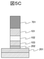
次にプラズマエッチングを用いて、ハードマスク層701をマスクとして、第1の強磁性層101、障壁層102、第2の強磁性層103、第1の非磁性層202を加工する。図5Cはプラズマエッチングによる加工を施した後の断面形状である。なお、図5Cでは、プラズマエッチングは第3の強磁性層201の表面で停止したように示しているが、実際は、第1の非磁性層202の途中(第3の強磁性層201の表面に達する前)で停止しても良い。第3の強磁性層201と第1の強磁性層101との間に段差が形成されていればよいためである。なお、プラズマエッチングの作用により、ハードマスク層701の膜厚も当初の厚さから薄くなる(~50nm)。
Next, plasma etching is used to process the first
次に、化学気相成長(CVD:Chemical Vapor Deposition)を用いて側壁堆積層702をコンフォーマルに成膜したときの断面図を図5Dに示す。この工程直前のMTJ素子の状態は、強磁性層及び障壁層が露出しているので、大気に曝すことなく真空中でCVD成膜装置まで搬送することが望ましい。側壁堆積層702にはSiNを用いるが、SiOなどの絶縁性を有する他の材料でも適用することが可能である。この側壁堆積層702は、第3の強磁性層201をプラズマエッチングする際のマスクになる役割がある。作製するMTJ素子について、第1の非磁性層202、第2の強磁性層103、障壁層102、第1の強磁性層101は直径20nmの円柱形状とし、第3の強磁性層201は直径30nmの円柱形状とする。このため、第1の非磁性層202、第2の強磁性層103、障壁層102及び第1の強磁性層101の側壁に堆積する側壁堆積層702の膜厚は5nmであれば良い。5nmの膜厚の側壁堆積層702と元々の20nmのハードマスク層701をマスクとしてプラズマエッチングすることで、5nm+20nm+5nm=30nm直径の円柱形状である第3の強磁性層201が得られる。プラズマエッチングで第3の強磁性層201を加工した後の断面形状を図5Eに示す。
Next, FIG. 5D shows a cross-sectional view when the side
その後、さらに層間絶縁膜703をCVDによって堆積し、化学機械研磨(CMP:Chemical Mechanical Polishing)やエッチングバック処理によってハードマスク層701の上部をコンタクト開口し、上部電極704を作製してプロセスが完了する。プロセス完了後の断面形状を図5Fに示す。このプロセスの利点は、側壁に積層した層間絶縁膜をマスクとしたセルフアライメントのプロセスであるため、マスクを追加する必要がなくコストが抑えられる点である。また、各層の膜厚や面積の差などがセルフアライメントのプロセスが適用しやすいという点も有利である。
After that, the
図5A~図5Fにて説明したプロセス(第1のプロセス)では、マスクとする側壁堆積層702として1層のSiN層を例示した。しかし、プラズマエッチングする際の、被エッチング材料である磁性体との選択比を考慮した場合、エッチングマスクとしてTaに代表される金属マスクを用いることが望ましい。そこでTaを側壁に積層してマスクとして利用するプロセス例(第2のプロセス)を以下に説明する。
In the process described with reference to FIGS. 5A to 5F (first process), one SiN layer was exemplified as the side
図5A~図5Cまでは同じプロセスフローであるので、説明を省略する。この後、図6Aに示すように、2nm膜厚の側壁堆積層801及び3nm膜厚の側壁金属(Ta)マスク層802をこの順に積層する。その後、これらの側壁堆積層801及び側壁金属マスク層802をマスクとしてプラズマエッチングで第3の強磁性層201を加工する。プラズマエッチングによる加工後の断面形状を図6Bに示す。さらに層間絶縁膜803をCVDによって堆積し、CMPやエッチングバック処理によってハードマスク層701の上部をコンタクト開口し、上部電極804を作製してプロセスが完了する。プロセス完了後の断面形状を図6Cに示す。
Since the process flow is the same from FIG. 5A to FIG. 5C, the description thereof will be omitted. After that, as shown in FIG. 6A, the side
磁性膜との選択比が大きい側壁金属マスクを用いることで、加工中のマスクの後退を最小限に抑えられ、加工後の形状における側壁エッチング角度が90度により近くなる。また、側壁金属マスク層802は、第3の強磁性層201を加工した後に除去しても良い。側壁金属マスク層802としてTaを用いた場合は、図6Bのプロセスの後、側壁金属マスク層802のTaを酸化後に、シュウ酸によるウェットエッチングで除去可能である。側壁金属マスク層802を残しておくと、側壁金属マスク層802がショートパスとしてMTJ素子の短絡原因になる可能性があるため、側壁金属マスク層802を除去することによりMTJ素子で短絡が生じるおそれを低減できる。
By using the side wall metal mask having a large selection ratio with the magnetic film, the retreat of the mask during processing can be minimized, and the side wall etching angle in the processed shape becomes closer to 90 degrees. Further, the side wall
第1、第2のプロセスは、図4に示したMTJ素子の作製にも適用できる。この場合は、素子の構造にあわせて、下部電極上に、第1の磁性多層膜層、第1の非磁性層、第2の磁性多層膜層、第2の非磁性層、第2の強磁性層、障壁層、第1の強磁性層を下から順に積層し、さらに加工のためのハードマスク層を積層して積層膜とする。その後の加工は、どちらのプロセスについてもほぼ同様である。図4の構造では、第2の磁性多層膜層と第1の磁性多層膜層との間に段差を設けるため、図5Cに示したプラズマエッチングの工程においては第1の磁性多層膜層の表面または第1の非磁性層の途中(第1の磁性多層膜層の表面に達する前)で停止するようにする。 The first and second processes can also be applied to the fabrication of the MTJ device shown in FIG. In this case, the first magnetic multilayer film layer, the first non-magnetic layer, the second magnetic multilayer film layer, the second non-magnetic layer, and the second strength are placed on the lower electrode according to the structure of the element. The magnetic layer, the barrier layer, and the first ferromagnetic layer are laminated in order from the bottom, and a hard mask layer for processing is further laminated to form a laminated film. Subsequent processing is similar for both processes. In the structure of FIG. 4, since a step is provided between the second magnetic multilayer film layer and the first magnetic multilayer film layer, the surface of the first magnetic multilayer film layer is provided in the plasma etching step shown in FIG. 5C. Alternatively, it is stopped in the middle of the first non-magnetic layer (before reaching the surface of the first magnetic multilayer film layer).
以上の実施の形態では、積層フェリ型参照層を構成する2つの強磁性層の物理的な面積を異ならせることにより段差を作製する例を示した。これに対して、物理的な面積差をつけて段差を設けるのではなく、2つの強磁性層の間で磁性体として有効に作用する面積を異ならせることで同様の効果を奏するMTJ素子の構造及びその作製方法を説明する(第3のプロセス)。 In the above embodiment, an example of creating a step by making the physical areas of the two ferromagnetic layers constituting the laminated ferri-type reference layer different from each other is shown. On the other hand, the structure of the MTJ element that achieves the same effect by making the area that effectively acts as a magnetic material different between the two ferromagnetic layers, instead of providing a step by making a physical area difference. And the method for producing the same will be described (third process).
図5A~図5Bまでは同じプロセスフローであるので、説明を省略する。その後、プラズマエッチングを用いて、ハードマスク層701をマスクとして、第1の強磁性層101、障壁層102の順に加工を施す。図7Aはプラズマエッチングによる加工を施した後の断面形状である。図7Aでは、プラズマエッチングは第2の強磁性層103の表面で停止したように示しているが、実際は、第2の強磁性層103の途中(第1の非磁性層202の表面に達する前)で停止しても良い。
Since the process flow from FIG. 5A to FIG. 5B is the same, the description thereof will be omitted. Then, using plasma etching, the
次の工程では、第2の強磁性層103に対して、障壁層102直下部分の磁化は残し、残りの部分の磁化を消失させる。磁化を消失させる方法の一つは酸化である。酸化の方法としては自然酸化、プラズマ酸化などが考えられる。自然酸化の場合は、酸素導入可能な処理室にMTJ素子を移してから酸素を導入する。この際、大気曝露せずに処理室に移動できるほうが望ましい。また、プラズマ酸化の場合、酸素ラジカルのみ導入する場合と、酸素イオンを導入する場合が考えられる。どちらの場合も、酸化処理をプラズマエッチング室と別の処理室で酸化する場合は、大気曝露を避けるほうが望ましい。
In the next step, the magnetization of the portion directly below the
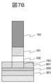
一般的に酸素ラジカルの場合は、酸素イオンを導入する場合と比較してダメージが小さいことが利点である。一方、酸素イオンを導入する場合、イオンが加速されるためダメージが大きいが、第2の強磁性層103に向かって上方からイオンが注入されるため酸化を促進しやすいという利点もある。このような工程を経ることによって、図7Bに示したように、障壁層102直下部分の磁化は残し、残りの部分の磁化を消失させ磁化消失層901とすることが可能である。
Generally, in the case of oxygen radicals, it is an advantage that the damage is smaller than that in the case of introducing oxygen ions. On the other hand, when oxygen ions are introduced, the ions are accelerated and the damage is large, but there is also an advantage that the ions are injected from above toward the second
このプロセスでは、第1の強磁性層101及び障壁層102をプラズマエッチングする際にMTJ素子側壁に付着する側壁再付着物も、第2の強磁性層103の酸化プロセスにおいて同時に酸化して不導体化することにより、側壁からのリーク電流を抑制できる利点がある。
In this process, the side wall reattachment adhering to the side wall of the MTJ element when plasma etching the first
酸化工程の後、図7Cに示すように、5nmの膜厚の側壁堆積層902をCVDによって積層する。その後、側壁堆積層902をマスクとしてプラズマエッチングで磁化消失層901、第1の非磁性層202、第3の強磁性層201を加工する。プラズマエッチングによる加工後の断面形状を図7Dに示す。さらに層間絶縁膜903をCVDによって堆積し、CMPやエッチングバック処理によってハードマスク層701の上部をコンタクト開口し、上部電極904を作製してプロセスが完了する。プロセス完了後の断面形状を図7Eに示す。このように、積層フェリ型参照層を構成する各層の面積は同じであるが、上層において強磁性層としての有効面積が狭められたことにより、物理的に段差を設けたのと同様の効果を得ることができる。なお、酸化工程の後、第2のプロセスのように側壁堆積層に金属層を形成し、側壁堆積層及び側壁金属マスク層をマスクとしてプラズマエッチングを行うようにしてもよい。
After the oxidation step, as shown in FIG. 7C, the side
上述のプロセスでは磁化消失層901を作製するために酸化処理を施したが、イオン注入により高エネルギーのイオンを照射することにより磁化を消失させることも可能である。この方法を用いる場合は、イオンが第2の強磁性層103に進入する深さを制御できるため、磁化消失層901の厚さ制御が容易になる。
In the above process, an oxidation treatment was performed to prepare the
このように第3のプロセスで形成されたMTJ素子は、第1の強磁性層101が第1の径を有する第1の円柱形状をなし、第1の円柱を積層方向に投影した領域と同じ大きさの断面を有する第2の強磁性層103、及び少なくとも第2の強磁性層103が第1の非磁性層202に接する面において第2の強磁性層103の全周を覆うように形成された磁化消失層901が、第1の径よりも大きい第2の径を有する第2の円柱形状をなし、第3の強磁性層201は、第2の円柱を積層方向に投影した領域と同じ大きさの断面を有する。
The MTJ element thus formed in the third process has the same shape as the first columnar shape in which the first
第3のプロセスもまた、図4に示したMTJ素子の作製にも適用できる。この場合は、素子の構造にあわせて、下部電極上に、第1の磁性多層膜層、第1の非磁性層、第2の磁性多層膜層、第2の非磁性層、第2の強磁性層、障壁層、第1の強磁性層を下から順に積層し、さらに加工のためのハードマスク層を積層して積層膜とする。その後の加工は、どちらのプロセスについてもほぼ同様である。図4の構造では、図7Bに示したプラズマエッチングの工程においては第2の磁性多層膜層の表面または途中(第1の非磁性層の表面に達する前)で停止するようにする。 The third process can also be applied to the fabrication of the MTJ device shown in FIG. In this case, the first magnetic multilayer film layer, the first non-magnetic layer, the second magnetic multilayer film layer, the second non-magnetic layer, and the second strength are placed on the lower electrode according to the structure of the element. The magnetic layer, the barrier layer, and the first ferromagnetic layer are laminated in order from the bottom, and a hard mask layer for processing is further laminated to form a laminated film. Subsequent processing is similar for both processes. In the structure of FIG. 4, in the plasma etching step shown in FIG. 7B, the process is stopped at the surface or in the middle of the second magnetic multilayer film layer (before reaching the surface of the first non-magnetic layer).
このように第3のプロセスで形成されたMTJ素子は、第1の強磁性層101、障壁層102、第2の強磁性層103が第1の径を有する第1の円柱形状をなし、第1の円柱を積層方向に投影した領域と同じ大きさの断面を有する第2の磁性多層膜層403、及び少なくとも第2の磁性多層膜層403が第1の非磁性層402に接する面において第2の磁性多層膜層403の全周を覆うように形成された磁化消失層901が、第1の径よりも大きい第2の径を有する第2の円柱形状をなし、第1の磁性多層膜層401は、第2の円柱を積層方向に投影した領域と同じ大きさの断面を有する。
In the MTJ element thus formed in the third process, the first
実施例1のMTJ素子は、記録層が参照層の上方に位置する構造(「ボトムピン型構造」という)であった。同様に、記録層が参照層の下方に位置する構造(「トップピン型構造」という)においても、参照層を積層フェリ型参照層とし、2つの強磁性層の面積を異ならせることにより、同様の効果を得ることができる。 The MTJ element of Example 1 had a structure in which the recording layer was located above the reference layer (referred to as “bottom pin type structure”). Similarly, in a structure in which the recording layer is located below the reference layer (referred to as “top pin type structure”), the reference layer is used as a laminated ferri-type reference layer, and the areas of the two ferromagnetic layers are different. The effect of can be obtained.
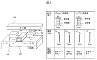
トップピン型構造とする利点について説明する。MRAMでは1個のMTJ素子に対して1個の選択トランジスタが直列に接続されている。図8にMRAMの1ビットの鳥瞰図を示す。シリコン基板300に選択トランジスタ301が形成され、選択トランジスタ301のドレイン電極302とビット線303との間にMTJ素子304が形成されている。図に示されるように、選択トランジスタ301はMTJ素子304の下層に配置される。この場合、図8に示すように、MTJ素子への書き込み時に選択トランジスタが供給できる電流は、選択トランジスタからMTJ素子に流れるとき((b),(d))に小さく、MTJ素子から選択トランジスタに流れるとき((a),(c))に大きい。一方、MTJ素子の磁化反転動作を行うために必要な電流は、一般的に平行状態から反平行状態への書き込みの場合が大きい。MTJ素子がボトムピン型構造の場合は、平行状態から反平行状態への書き込みの電流方向が選択トランジスタからMTJ素子方向となるため、必要な電流を流すために選択トランジスタの電流供給能力を高める必要がある。MTJ素子がトップピン構造の場合は、電流がMTJ素子から選択トランジスタに流れる場合に平行状態から反平行状態への書き込みとなるため、より電流供給能力の低い選択トランジスタでも反平行状態への書き込みが問題なく行えることとなり、有利である。
The advantages of the top pin type structure will be described. In MRAM, one selection transistor is connected in series to one MTJ element. FIG. 8 shows a 1-bit bird's-eye view of the MRAM. The
トップピン構造としたMTJ素子の構造(第3の構造例)について図9を用いて説明する。図9はMTJ素子(第3の構造例)の断面図である。第1の強磁性層501、障壁層502、第2の強磁性層503、第1の非磁性層504、第3の強磁性層505を下部電極の上に下から順に積層した積層膜を加工して作製される。第2の強磁性層503、第1の非磁性層504、第3の強磁性層505は積層フェリ型参照層506を構成する。第2の強磁性層503の磁化508、及び第3の強磁性層505の磁化509が互いに反平行に結合するように、第1の非磁性層504の材料と膜厚が決定される。第1の強磁性層501は記録層として動作する。
The structure of the MTJ element having a top pin structure (third structural example) will be described with reference to FIG. FIG. 9 is a cross-sectional view of the MTJ element (third structural example). A laminated film in which a first
MTJ素子は柱状に加工され、積層フェリ型参照層506を構成する第2の強磁性層503と第3の強磁性層505の面積が異なるように加工されている。図9の例では、第2の強磁性層503の面積が、第3の強磁性層505より小さくなるように加工されている。これにより、第2の強磁性層503と第3の強磁性層505との間で段差がある構造となる。
The MTJ element is processed into a columnar shape so that the areas of the second
同様に、Co/Pt多層膜を用いた場合のトップピン構造も作製可能である。Co/Pt多層膜を用いたトップピン構造のMTJ素子600の断面図を図10に示す。第1の強磁性層601、障壁層602、第2の強磁性層603、第2の非磁性層604、第2の磁性多層膜層605、第1の非磁性層606、第1の磁性多層膜層607を下部電極の上に下から順に積層した積層膜を加工して作製される。第2の強磁性層603、第2の非磁性層604、第2の磁性多層膜層605、第1の非磁性層606、第1の磁性多層膜層607は積層フェリ型参照層608を構成する。第2の強磁性層603の磁化610、及び第2の磁性多層膜層605の磁化611は互いに平行に結合するように、第2の非磁性層604の材料と膜厚が決定される。第2の磁性多層膜層605の磁化611、及び第1の磁性多層膜層607の磁化612は互いに反平行に結合するように、第1の非磁性層606の材料と膜厚が決定される。第1の強磁性層601は記録層として動作する。
Similarly, a top pin structure can be produced when a Co / Pt multilayer film is used. FIG. 10 shows a cross-sectional view of the
以上説明したMTJ素子をメモリセルの記憶素子としてMRAMを構成することができる。図11にMRAMのメモリアレイ1100を示す。図8に示したようにメモリセル1000は、MTJ素子とそのソース・ドレイン経路がMTJ素子に直列接続される選択トランジスタとで構成される。ここでは、MTJ素子として図2に示したMTJ素子200を用いている。
The MRAM can be configured by using the MTJ element described above as a storage element of a memory cell. FIG. 11 shows the
メモリセル1000のMTJ素子200は、第3の強磁性層201の下部に配置されている下部電極が選択トランジスタ1001のドレイン電極と電気的に接続されている。また、第1の強磁性層101の上部に配置されている上部電極はビット線(BL)1002に電気的に接続されている。選択トランジスタ1001のソース電極は、ビット線1002と平行に配置されるソース線(SL)1003に電気的に接続されている。選択トランジスタ1001のゲート電極は、ビット線及びソース線と直交するように配置されるワード線(WL)1004に接続されている。
In the
図11に示される通り、ビット線1002、ソース線1003、及びワード線1004は複数配置され、ビット線1002及びソース線1003とワード線1004とが交差する各点に、メモリセル1000が配置される。各ビット線1002、ソース線1003、ワード線1004はそれぞれ独立に電圧を制御する機構が設置されている。
As shown in FIG. 11, a plurality of
特定のメモリセル1000を選択するときは、そのメモリセル1000が電気的に接続しているビット線1002及びソース線1003の電圧を制御し、そのMTJ素子が接続しているワード線1004に電圧を印加することで選択トランジスタ1001に電流が印加される状態となる。例えば、MTJ素子200を低抵抗状態に書き込みする場合、ソース線1003の電位と比較してビット線1002の電位が高くなるように設定する。この状態でワード線1004に電圧を印加すると、MTJ素子200の上部電極から下部電極に向かって電流が流れる。電流がMTJ素子200の書き込み閾値電流を超えるとMTJ素子200は低抵抗状態になる。
When selecting a
なお、MTJ素子を使用するデバイス例として、MRAMメモリアレイ1100を示したが、磁気センサ等、他のデバイスにも適用することが可能である。
Although the
以上、本発明について説明したが、実施の形態に限定されるものではなく、様々な変形例が含まれる。実施の形態は本発明を分かりやすく説明するために詳細に説明したものであり、必ずしも説明した全ての構成を備えるものに限定されるものではない。また、実施の形態の構成の一部について、他の構成の追加、削除、置換をすることも可能である。 Although the present invention has been described above, the present invention is not limited to the embodiments, and various modifications are included. The embodiments have been described in detail in order to explain the present invention in an easy-to-understand manner, and are not necessarily limited to those having all the described configurations. It is also possible to add, delete, or replace a part of the configuration of the embodiment with another configuration.
100,200,400:MTJ素子、101:第1の強磁性層、102:障壁層、103:第2の強磁性層、201:第3の強磁性層、202:第1の非磁性層、203,405:積層フェリ型参照層、401:第1の磁性多層膜層、402:第1の非磁性層、403:第2の磁性多層膜層、404:第2の非磁性層、500,600:MTJ素子、501,601:第1の強磁性層、502,602:障壁層、503,603:第2の強磁性層、504:第1の非磁性層、505:第3の強磁性層、506,608:積層フェリ型参照層、604:第2の非磁性層、605:第2の磁性多層膜層、606:第1の非磁性層、607:第1の磁性多層膜層、700:積層膜、701:ハードマスク層、702,801,902:側壁堆積層、703,803,903:層間絶縁膜、704,804,904:上部電極、802:側壁金属マスク層、901:磁化消失層、1000:メモリセル、1001:選択トランジスタ、1002:ビット線、1003:ソース線、1004:ワード線、1100:メモリアレイ。 100, 200, 400: MTJ element, 101: first ferromagnetic layer, 102: barrier layer, 103: second ferromagnetic layer, 201: third ferromagnetic layer, 202: first non-magnetic layer, 203, 405: laminated ferri type reference layer, 401: first magnetic multilayer film layer, 402: first non-magnetic layer, 403: second magnetic multilayer film layer, 404: second non-magnetic layer, 500, 600: MTJ element, 501,601: 1st ferromagnetic layer, 502,602: barrier layer, 503,603: 2nd ferromagnetic layer, 504: 1st non-magnetic layer, 505: 3rd ferromagnetic layer Layers, 506: 608: laminated ferri-type reference layer, 604: second non-magnetic layer, 605: second magnetic multilayer film layer, 606: first non-magnetic layer, 607: first magnetic multilayer film layer, 700: Laminated film, 701: Hard mask layer, 702,801,902: Side wall deposition layer, 703,803,903: Interlayer insulating film, 704,804,904: Top electrode, 802: Side wall metal mask layer, 901: Magnetism Vanishing layer, 1000: memory cell, 1001: selection transistor, 1002: bit line, 1003: source line, 1004: word line, 1100: memory array.
Claims (6)
第1の強磁性層と、前記第1の強磁性層の下方に配置された障壁層と、第1の磁化方向を有し前記障壁層の下方に配置された第2の強磁性層と、前記第2の強磁性層の下方に配置された第1の非磁性層と、前記第1の磁化方向と反平行である第2の磁化方向を有し前記第1の非磁性層の下方に配置された第3の強磁性層とを有しハードマスク層が前記第1の強磁性層の上方に形成された積層膜を形成し、
前記ハードマスク層を円柱形状にパターニングし、
前記パターニングされたハードマスク層をマスクとして前記積層膜を前記第3の強磁性層表面または前記第1の非磁性層の途中までプラズマエッチングし、
前記パターニングされた前記積層膜に側壁堆積層を化学気相成長により積層し、
金属層を前記側壁堆積層に積層して前記パターニングされたハードマスク層、前記側壁堆積層および前記金属層をマスクとして前記第3の強磁性層をプラズマエッチングし、
前記パターニングされたハードマスク層、前記側壁堆積層および前記金属層をマスクとしてプラズマエッチングを行った後、前記金属層を除去し、
前記第1の磁化方向は、前記積層膜の積層方向と平行であり、
前記第1の非磁性層の材料および膜厚は、前記第3の強磁性層の磁化方向が前記第2の強磁性層の磁化方向と反平行となる材料および膜厚とされ、
前記パターニングされた第2の強磁性層、第1の非磁性層および第3の強磁性層により前記磁気トンネル接合素子の積層フェリ型参照層が構成され、
前記第3の強磁性層の直径は、前記積層フェリ型参照層から前記第1の強磁性層への漏れ磁場の絶対値が概ね0となる直径とされていることを特徴とする磁気トンネル接合素子の製造方法。 In the method of manufacturing a magnetic tunnel junction element
A first ferromagnetic layer, a barrier layer arranged below the first ferromagnetic layer, and a second ferromagnetic layer having a first magnetization direction and arranged below the barrier layer. A first non-magnetic layer arranged below the second ferromagnetic layer and a second non-magnetic layer having a second magnetization direction antiparallel to the first magnetization direction and below the first non-magnetic layer. A hard mask layer having an arranged third ferromagnetic layer forms a laminated film formed above the first ferromagnetic layer.
The hard mask layer is patterned into a cylindrical shape to form a cylinder.
Using the patterned hard mask layer as a mask, the laminated film is plasma-etched to the surface of the third ferromagnetic layer or the middle of the first non-magnetic layer.
A side wall sedimentary layer was laminated on the patterned laminated film by chemical vapor deposition, and then
The third ferromagnetic layer was plasma-etched by laminating the metal layer on the side wall deposit layer and using the patterned hard mask layer , the side wall deposit layer and the metal layer as masks.
After plasma etching was performed using the patterned hard mask layer, the side wall deposition layer and the metal layer as masks, the metal layer was removed.
The first magnetization direction is parallel to the laminating direction of the laminated film, and is parallel to the laminating direction of the laminated film.
The material and film thickness of the first non-magnetic layer are such that the magnetization direction of the third ferromagnetic layer is antiparallel to the magnetization direction of the second ferromagnetic layer.
The patterned second ferromagnetic layer, the first non-magnetic layer and the third ferromagnetic layer constitute a laminated ferri-type reference layer of the magnetic tunnel junction element.
The diameter of the third ferromagnetic layer is a magnetic tunnel junction characterized in that the absolute value of the leakage magnetic field from the laminated ferri-type reference layer to the first ferromagnetic layer is approximately 0. Method of manufacturing the element.
上層から順に第1の強磁性層、障壁層、第2の強磁性層、第1の非磁性層および第3の強磁性層を有しハードマスク層が前記第1の強磁性層の上方に形成された積層膜を形成し、
前記ハードマスク層を円柱形状にパターニングし、
前記パターニングされたハードマスク層をマスクとして前記積層膜を前記第2の強磁性層表面または途中までプラズマエッチングし、
前記パターニングされたハードマスク層よりも外側領域の磁化を消失させることにより磁化消失層を前記第2の強磁性層に形成し、
パターニングされた前記積層膜に側壁堆積層を化学気相成長により積層し、
金属層を前記側壁堆積層に積層して前記パターニングされたハードマスク層、前記側壁堆積層および前記金属層をマスクとして前記磁化消失層、前記第1の非磁性層および前記第3の強磁性層をプラズマエッチングし、
前記パターニングされたハードマスク層、前記側壁堆積層および前記金属層をマスクとしてプラズマエッチングを行った後、前記金属層を除去し、
前記第2の強磁性層の材料および膜厚は、磁化方向が積層方向に対して平行となる材料および膜厚とされ、
前記第1の非磁性層の材料および膜厚は、前記第3の強磁性層の磁化方向が前記第2の強磁性層の磁化方向と反平行となる材料および膜厚とされ、
前記パターニングされた第2の強磁性層、第1の非磁性層および第3の強磁性層により前記磁気トンネル接合素子の積層フェリ型参照層が構成され、
前記磁化消失層の幅は、前記積層フェリ型参照層から前記第1の強磁性層への漏れ磁場の絶対値が概ね0となる幅とされていることを特徴とする磁気トンネル接合素子の製造方法。 In the method of manufacturing a magnetic tunnel junction element
A hard mask layer having a first ferromagnetic layer, a barrier layer, a second ferromagnetic layer, a first non-magnetic layer and a third ferromagnetic layer in order from the upper layer is above the first ferromagnetic layer. Form the formed laminated film,
The hard mask layer is patterned into a cylindrical shape to form a cylinder.
Using the patterned hard mask layer as a mask, the laminated film is plasma-etched on the surface or halfway of the second ferromagnetic layer.
By eliminating the magnetization in the region outside the patterned hard mask layer, the magnetization disappearing layer is formed in the second ferromagnetic layer.
A side wall sedimentary layer was laminated on the patterned laminated film by chemical vapor deposition, and then
The patterned hard mask layer by laminating a metal layer on the side wall deposition layer, the magnetization disappearing layer using the side wall deposition layer and the metal layer as a mask, the first non-magnetic layer and the third ferromagnetic layer. Plasma etched,
After plasma etching was performed using the patterned hard mask layer, the side wall deposition layer and the metal layer as masks, the metal layer was removed.
The material and film thickness of the second ferromagnetic layer are those whose magnetization direction is parallel to the stacking direction.
The material and film thickness of the first non-magnetic layer are such that the magnetization direction of the third ferromagnetic layer is antiparallel to the magnetization direction of the second ferromagnetic layer.
The patterned second ferromagnetic layer, the first non-magnetic layer and the third ferromagnetic layer constitute a laminated ferri-type reference layer of the magnetic tunnel junction element.
Manufacture of a magnetic tunnel junction element, wherein the width of the magnetization disappearing layer is such that the absolute value of the leakage magnetic field from the laminated ferri-type reference layer to the first ferromagnetic layer is approximately 0. Method.
上層から順に第1の強磁性層、障壁層、第2の強磁性層、第2の非磁性層、第2の磁性多層膜層、第1の非磁性層および第1の磁性多層膜層を有しハードマスク層が前記第1の強磁性層の上方に形成された積層膜を形成し、
前記ハードマスク層を円柱形状にパターニングし、
前記パターニングされたハードマスク層をマスクとして前記積層膜を前記第1の磁性多層膜層表面または前記第1の非磁性層の途中までプラズマエッチングし、
前記パターニングされた積層膜に側壁堆積層を化学気相成長により積層し、
金属層を前記側壁堆積層に積層して前記パターニングされたハードマスク層、前記側壁堆積層および前記金属層をマスクとして前記第1の磁性多層膜層をプラズマエッチングし、
前記パターニングされたハードマスク層、前記側壁堆積層および前記金属層をマスクとしてプラズマエッチングを行った後、前記金属層を除去し、
前記第1の非磁性層の材料および膜厚は、前記第1の磁性多層膜層の磁化方向が前記第2の磁性多層膜層の磁化方向と反平行となる材料及び膜厚とされ、
前記第2の非磁性層の材料および膜厚は、前記第2の強磁性層の磁化方向が前記第2の磁性多層膜層の磁化方向と平行となる材料及び膜厚とされ、
前記パターニングされた第2の強磁性層、第2の非磁性層、第2の磁性多層膜層、第1の非磁性層および第1の磁性多層膜層により前記磁気トンネル接合素子の積層フェリ型参照層が構成され、
前記第1の磁性多層膜層の直径は、前記積層フェリ型参照層から前記第1の強磁性層への漏れ磁場の絶対値が概ね0となる直径とされていることを特徴とする磁気トンネル接合素子の製造方法。 In the method of manufacturing a magnetic tunnel junction element
The first ferromagnetic layer, the barrier layer, the second ferromagnetic layer, the second non-magnetic layer, the second magnetic multilayer film layer, the first non-magnetic layer and the first magnetic multilayer film layer are arranged in this order from the upper layer. The hard mask layer has formed a laminated film formed above the first ferromagnetic layer.
The hard mask layer is patterned into a cylindrical shape to form a cylinder.
Using the patterned hard mask layer as a mask, the laminated film is plasma-etched to the surface of the first magnetic multilayer film layer or the middle of the first non-magnetic layer.
A side wall sedimentary layer is laminated on the patterned laminated film by chemical vapor deposition, and the sidewall is laminated.
The first magnetic multilayer film layer was plasma-etched by laminating the metal layer on the side wall deposit layer and using the patterned hard mask layer , the side wall deposit layer and the metal layer as masks.
After plasma etching was performed using the patterned hard mask layer, the side wall deposition layer and the metal layer as masks, the metal layer was removed.
The material and film thickness of the first non-magnetic layer are such that the magnetization direction of the first magnetic multilayer film layer is antiparallel to the magnetization direction of the second magnetic multilayer film layer.
The material and film thickness of the second non-magnetic layer are such that the magnetization direction of the second ferromagnetic layer is parallel to the magnetization direction of the second magnetic multilayer film layer.
The laminated ferri type of the magnetic tunnel junction element by the patterned second ferromagnetic layer, second non-magnetic layer, second magnetic multilayer film layer, first non-magnetic layer and first magnetic multilayer film layer. The reference layer is composed,
The diameter of the first magnetic multilayer film layer is a magnetic tunnel characterized in that the absolute value of the leakage magnetic field from the laminated ferri-type reference layer to the first ferromagnetic layer is approximately 0. Manufacturing method of junction element.
上層から順に第1の強磁性層、障壁層、第2の強磁性層、第2の非磁性層、第2の磁性多層膜層、第1の非磁性層および第1の磁性多層膜層を有しハードマスク層が前記第1の強磁性層の上方に形成された積層膜を形成し、
前記ハードマスク層を円柱形状にパターニングし、
前記パターニングされたハードマスク層をマスクとして前記積層膜を前記第2の磁性多層膜層表面または途中までプラズマエッチングし、
前記パターニングされたハードマスク層よりも外側領域の磁化を消失させることにより磁化消失層を前記第2の磁性多層膜層に形成し、
前記パターニングされた積層膜に側壁堆積層を化学気相成長により積層し、
金属層を前記側壁堆積層に積層して前記パターニングされたハードマスク層、前記側壁堆積層および前記金属層をマスクとして前記磁化消失層、前記第1の非磁性層および前記第1の磁性多層膜層をプラズマエッチングし、
前記パターニングされたハードマスク層、前記側壁堆積層および前記金属層をマスクとしてプラズマエッチングを行った後、前記金属層を除去し、
前記第1の非磁性層の材料および膜厚は、前記第1の磁性多層膜層の磁化方向が前記第2の磁性多層膜層の磁化方向と反平行となる材料及び膜厚とされ、
前記第2の非磁性層の材料および膜厚は、前記第2の強磁性層の磁化方向が前記第2の磁性多層膜層の磁化方向と平行となる材料及び膜厚とされ、
前記パターニングされた第2の強磁性層、第2の非磁性層、第2の磁性多層膜層、第1の非磁性層および第1の磁性多層膜層により前記磁気トンネル接合素子の積層フェリ型参照層が構成され、
前記磁化消失層の幅は、前記積層フェリ型参照層から前記第1の強磁性層への漏れ磁場の絶対値が概ね0となる幅とされていることを特徴とする磁気トンネル接合素子の製造方法。 In the method of manufacturing a magnetic tunnel junction element
The first ferromagnetic layer, the barrier layer, the second ferromagnetic layer, the second non-magnetic layer, the second magnetic multilayer film layer, the first non-magnetic layer and the first magnetic multilayer film layer are arranged in this order from the upper layer. The hard mask layer has formed a laminated film formed above the first ferromagnetic layer.
The hard mask layer is patterned into a cylindrical shape to form a cylinder.
Using the patterned hard mask layer as a mask, the laminated film is plasma-etched on the surface or halfway of the second magnetic multilayer film layer.
By eliminating the magnetization in the region outside the patterned hard mask layer, the magnetization disappearing layer is formed on the second magnetic multilayer film layer.
A side wall sedimentary layer is laminated on the patterned laminated film by chemical vapor deposition, and the sidewall is laminated.
The patterned hard mask layer by laminating the metal layer on the side wall deposition layer, the magnetization disappearing layer using the side wall deposition layer and the metal layer as a mask, the first non-magnetic layer and the first magnetic multilayer film. The layer is plasma etched and
After plasma etching was performed using the patterned hard mask layer, the side wall deposition layer and the metal layer as masks, the metal layer was removed.
The material and film thickness of the first non-magnetic layer are such that the magnetization direction of the first magnetic multilayer film layer is antiparallel to the magnetization direction of the second magnetic multilayer film layer.
The material and film thickness of the second non-magnetic layer are such that the magnetization direction of the second ferromagnetic layer is parallel to the magnetization direction of the second magnetic multilayer film layer.
The laminated ferri type of the magnetic tunnel junction element by the patterned second ferromagnetic layer, second non-magnetic layer, second magnetic multilayer film layer, first non-magnetic layer and first magnetic multilayer film layer. The reference layer is composed,
Manufacture of a magnetic tunnel junction element, wherein the width of the magnetization disappearing layer is such that the absolute value of the leakage magnetic field from the laminated ferri-type reference layer to the first ferromagnetic layer is approximately 0. Method.
前記側壁堆積層は、シリコン酸化物またはシリコン窒化物であることを特徴とする磁気トンネル接合素子の製造方法。 The method for manufacturing a magnetic tunnel junction element according to any one of claims 1 to 4 .
A method for manufacturing a magnetic tunnel junction element, wherein the side wall deposit layer is a silicon oxide or a silicon nitride.
酸化またはイオン注入により前記磁化消失層を形成することを特徴とする磁気トンネル接合素子の製造方法。 In the method for manufacturing a magnetic tunnel junction element according to claim 2 or 4 .
A method for manufacturing a magnetic tunnel junction element, which comprises forming the magnetization-disappearing layer by oxidation or ion implantation.
Priority Applications (4)
| Application Number | Priority Date | Filing Date | Title |
|---|---|---|---|
| JP2017153003A JP7023637B2 (en) | 2017-08-08 | 2017-08-08 | Manufacturing method of magnetic tunnel junction element |
| KR1020170181971A KR102285125B1 (en) | 2017-08-08 | 2017-12-28 | Magnetic tunnel junction device, magnetic memory using the same and method of manufacturing magnetic tunnel junction device |
| TW107103019A TWI716666B (en) | 2017-08-08 | 2018-01-29 | Magnetic tunnel junction element, magnetic memory using the same and manufacturing method of magnetic tunnel junction element |
| US15/906,775 US11165015B2 (en) | 2017-08-08 | 2018-02-27 | Magnetic tunnel junction device, magnetoresistive random access memory using same and manufacturing method of magnetic tunnel junction device |
Applications Claiming Priority (1)
| Application Number | Priority Date | Filing Date | Title |
|---|---|---|---|
| JP2017153003A JP7023637B2 (en) | 2017-08-08 | 2017-08-08 | Manufacturing method of magnetic tunnel junction element |
Publications (3)
| Publication Number | Publication Date |
|---|---|
| JP2019033167A JP2019033167A (en) | 2019-02-28 |
| JP2019033167A5 JP2019033167A5 (en) | 2020-06-11 |
| JP7023637B2 true JP7023637B2 (en) | 2022-02-22 |
Family
ID=65275889
Family Applications (1)
| Application Number | Title | Priority Date | Filing Date |
|---|---|---|---|
| JP2017153003A Active JP7023637B2 (en) | 2017-08-08 | 2017-08-08 | Manufacturing method of magnetic tunnel junction element |
Country Status (4)
| Country | Link |
|---|---|
| US (1) | US11165015B2 (en) |
| JP (1) | JP7023637B2 (en) |
| KR (1) | KR102285125B1 (en) |
| TW (1) | TWI716666B (en) |
Families Citing this family (3)
| Publication number | Priority date | Publication date | Assignee | Title |
|---|---|---|---|---|
| WO2018125634A1 (en) * | 2016-12-27 | 2018-07-05 | Everspin Technologies, Inc. | Data storage in synthetic antiferromagnets included in magnetic tunnel junctions |
| CN109904309B (en) * | 2019-03-19 | 2023-04-18 | 中国科学院微电子研究所 | Multi-state magnetic memory and manufacturing method thereof |
| CN112531106A (en) * | 2019-09-18 | 2021-03-19 | 中电海康集团有限公司 | Preparation method of magnetic tunnel junction |
Citations (5)
| Publication number | Priority date | Publication date | Assignee | Title |
|---|---|---|---|---|
| JP2009514211A (en) | 2005-10-28 | 2009-04-02 | インターナショナル・ビジネス・マシーンズ・コーポレーション | Tuned pinned layer for magnetic tunnel junction with multi-component free layer |
| JP2013093349A (en) | 2011-10-24 | 2013-05-16 | Toshiba Corp | Magnetic storage element |
| JP2014229758A (en) | 2013-05-22 | 2014-12-08 | ソニー株式会社 | Semiconductor device and manufacturing method of the same |
| JP2017059690A (en) | 2015-09-16 | 2017-03-23 | 株式会社東芝 | Magnetic element and storage device |
| US20170222132A1 (en) | 2016-01-28 | 2017-08-03 | Spin Transfer Technologies, Inc. | Memory cell having magnetic tunnel junction and thermal stability enhancement layer |
Family Cites Families (23)
| Publication number | Priority date | Publication date | Assignee | Title |
|---|---|---|---|---|
| US6781173B2 (en) * | 2002-08-29 | 2004-08-24 | Micron Technology, Inc. | MRAM sense layer area control |
| JP2006261592A (en) * | 2005-03-18 | 2006-09-28 | Fujitsu Ltd | Magnetoresistance effect element and its manufacture |
| JP2007266498A (en) * | 2006-03-29 | 2007-10-11 | Toshiba Corp | Magnetic recording element and magnetic memory |
| JP2008283018A (en) * | 2007-05-11 | 2008-11-20 | Tdk Corp | Tunnel-type magnetic detecting element and manufacturing method thereof |
| JP5157268B2 (en) * | 2007-06-13 | 2013-03-06 | 株式会社日立製作所 | Spin accumulation magnetization reversal type memory device and spin RAM |
| JP5260040B2 (en) * | 2007-12-19 | 2013-08-14 | 株式会社日立製作所 | Unidirectional current magnetization reversal magnetoresistive element and magnetic recording apparatus |
| US8223533B2 (en) * | 2008-09-26 | 2012-07-17 | Kabushiki Kaisha Toshiba | Magnetoresistive effect device and magnetic memory |
| US8344433B2 (en) * | 2009-04-14 | 2013-01-01 | Qualcomm Incorporated | Magnetic tunnel junction (MTJ) and methods, and magnetic random access memory (MRAM) employing same |
| US8362580B2 (en) * | 2009-12-08 | 2013-01-29 | Qualcomm Incorporated | Spin-transfer switching magnetic element utilizing a composite free layer comprising a superparamagnetic layer |
| US8981502B2 (en) * | 2010-03-29 | 2015-03-17 | Qualcomm Incorporated | Fabricating a magnetic tunnel junction storage element |
| JP5725735B2 (en) | 2010-06-04 | 2015-05-27 | 株式会社日立製作所 | Magnetoresistive element and magnetic memory |
| JP5492144B2 (en) | 2011-05-27 | 2014-05-14 | 株式会社日立製作所 | Perpendicular magnetoresistive element and magnetic memory |
| US9054030B2 (en) * | 2012-06-19 | 2015-06-09 | Micron Technology, Inc. | Memory cells, semiconductor device structures, memory systems, and methods of fabrication |
| US8747680B1 (en) * | 2012-08-14 | 2014-06-10 | Everspin Technologies, Inc. | Method of manufacturing a magnetoresistive-based device |
| US9231191B2 (en) * | 2012-08-20 | 2016-01-05 | Industrial Technology Research Institute | Magnetic tunnel junction device and method of making same |
| US9373775B2 (en) * | 2012-09-13 | 2016-06-21 | Micron Technology, Inc. | Methods of forming magnetic memory cells |
| JP5571142B2 (en) | 2012-09-25 | 2014-08-13 | 株式会社東芝 | Magnetic memory |
| KR20160022809A (en) * | 2013-06-21 | 2016-03-02 | 인텔 코포레이션 | Mtj spin hall mram bit-cell and array |
| JP5752831B2 (en) | 2014-05-07 | 2015-07-22 | 株式会社東芝 | Magnetic memory |
| US9576636B1 (en) * | 2015-04-03 | 2017-02-21 | Everspin Technologies, Inc. | Magnetic memory having ROM-like storage and method therefore |
| JP2018073913A (en) * | 2016-10-26 | 2018-05-10 | 株式会社デンソー | Magnetic sensor and production method thereof |
| WO2018125634A1 (en) * | 2016-12-27 | 2018-07-05 | Everspin Technologies, Inc. | Data storage in synthetic antiferromagnets included in magnetic tunnel junctions |
| US10794968B2 (en) * | 2017-08-24 | 2020-10-06 | Everspin Technologies, Inc. | Magnetic field sensor and method of manufacture |
-
2017
- 2017-08-08 JP JP2017153003A patent/JP7023637B2/en active Active
- 2017-12-28 KR KR1020170181971A patent/KR102285125B1/en active IP Right Grant
-
2018
- 2018-01-29 TW TW107103019A patent/TWI716666B/en active
- 2018-02-27 US US15/906,775 patent/US11165015B2/en active Active
Patent Citations (5)
| Publication number | Priority date | Publication date | Assignee | Title |
|---|---|---|---|---|
| JP2009514211A (en) | 2005-10-28 | 2009-04-02 | インターナショナル・ビジネス・マシーンズ・コーポレーション | Tuned pinned layer for magnetic tunnel junction with multi-component free layer |
| JP2013093349A (en) | 2011-10-24 | 2013-05-16 | Toshiba Corp | Magnetic storage element |
| JP2014229758A (en) | 2013-05-22 | 2014-12-08 | ソニー株式会社 | Semiconductor device and manufacturing method of the same |
| JP2017059690A (en) | 2015-09-16 | 2017-03-23 | 株式会社東芝 | Magnetic element and storage device |
| US20170222132A1 (en) | 2016-01-28 | 2017-08-03 | Spin Transfer Technologies, Inc. | Memory cell having magnetic tunnel junction and thermal stability enhancement layer |
Also Published As
| Publication number | Publication date |
|---|---|
| TWI716666B (en) | 2021-01-21 |
| TW201911536A (en) | 2019-03-16 |
| JP2019033167A (en) | 2019-02-28 |
| KR20190016420A (en) | 2019-02-18 |
| US11165015B2 (en) | 2021-11-02 |
| US20190051819A1 (en) | 2019-02-14 |
| KR102285125B1 (en) | 2021-08-04 |
Similar Documents
| Publication | Publication Date | Title |
|---|---|---|
| JP5537791B2 (en) | Manufacturing method of MTJ element | |
| JP5571142B2 (en) | Magnetic memory | |
| TWI575788B (en) | Magnetic memory and method of manufacturing magnetic memory | |
| JP4458703B2 (en) | Magnetoresistive element, manufacturing method thereof, magnetic random access memory, portable terminal device, magnetic head, and magnetic reproducing device | |
| JP5502627B2 (en) | Magnetic random access memory and manufacturing method thereof | |
| JP2013058521A (en) | Storage device and method for manufacturing the same | |
| US9461243B2 (en) | STT-MRAM and method of manufacturing the same | |
| JP2017112358A (en) | Bottom pinned sot-mram bit structure and method of fabrication | |
| JP2017510995A (en) | Replacement conductive hardmask for multi-step magnetic tunnel junction (MTJ) etching | |
| KR102447763B1 (en) | Magnetic tunnel junction device, magnetic memory using the same, and method for manufacturing the same | |
| WO2006092849A1 (en) | Magnetoresistive element and magnetic memory | |
| JP5019344B2 (en) | Magnetoresistive memory including MTJ layer having tunnel film of uniform thickness and manufacturing method thereof | |
| JP7023637B2 (en) | Manufacturing method of magnetic tunnel junction element | |
| JP2005064075A (en) | Magnetic storage device and its manufacturing method | |
| JP5686626B2 (en) | Magnetic memory and manufacturing method thereof | |
| US20130113058A1 (en) | Magnetic memory element, magnetic memory and manufacturing method of the same | |
| US20160087004A1 (en) | Magnetic memory and method of manufacturing the same | |
| JP2008282940A (en) | Method for manufacturing magnetic storage device | |
| JP5752831B2 (en) | Magnetic memory | |
| JP2005166896A (en) | Magnetic memory | |
| JP4970821B2 (en) | Magnetic memory device | |
| JP2002151660A (en) | Magnetic random access memory and magnetic information write method | |
| JP3935049B2 (en) | Magnetic storage device and manufacturing method thereof | |
| US20160072054A1 (en) | Method to make mram with small cell size | |
| KR20210018696A (en) | Magnetic memory device |
Legal Events
| Date | Code | Title | Description |
|---|---|---|---|
| A521 | Request for written amendment filed |
Free format text: JAPANESE INTERMEDIATE CODE: A523 Effective date: 20200122 |
|
| A621 | Written request for application examination |
Free format text: JAPANESE INTERMEDIATE CODE: A621 Effective date: 20200122 |
|
| A521 | Request for written amendment filed |
Free format text: JAPANESE INTERMEDIATE CODE: A523 Effective date: 20200422 |
|
| A131 | Notification of reasons for refusal |
Free format text: JAPANESE INTERMEDIATE CODE: A131 Effective date: 20201201 |
|
| A977 | Report on retrieval |
Free format text: JAPANESE INTERMEDIATE CODE: A971007 Effective date: 20201130 |
|
| A601 | Written request for extension of time |
Free format text: JAPANESE INTERMEDIATE CODE: A601 Effective date: 20210126 |
|
| A521 | Request for written amendment filed |
Free format text: JAPANESE INTERMEDIATE CODE: A523 Effective date: 20210325 |
|
| A02 | Decision of refusal |
Free format text: JAPANESE INTERMEDIATE CODE: A02 Effective date: 20210824 |
|
| A521 | Request for written amendment filed |
Free format text: JAPANESE INTERMEDIATE CODE: A523 Effective date: 20211118 |
|
| C60 | Trial request (containing other claim documents, opposition documents) |
Free format text: JAPANESE INTERMEDIATE CODE: C60 Effective date: 20211118 |
|
| A911 | Transfer to examiner for re-examination before appeal (zenchi) |
Free format text: JAPANESE INTERMEDIATE CODE: A911 Effective date: 20211129 |
|
| C21 | Notice of transfer of a case for reconsideration by examiners before appeal proceedings |
Free format text: JAPANESE INTERMEDIATE CODE: C21 Effective date: 20211130 |
|
| TRDD | Decision of grant or rejection written | ||
| A01 | Written decision to grant a patent or to grant a registration (utility model) |
Free format text: JAPANESE INTERMEDIATE CODE: A01 Effective date: 20220118 |
|
| A61 | First payment of annual fees (during grant procedure) |
Free format text: JAPANESE INTERMEDIATE CODE: A61 Effective date: 20220209 |
|
| R150 | Certificate of patent or registration of utility model |
Ref document number: 7023637 Country of ref document: JP Free format text: JAPANESE INTERMEDIATE CODE: R150 |