JP7021619B2 - Transformers and power converters - Google Patents
Transformers and power converters Download PDFInfo
- Publication number
- JP7021619B2 JP7021619B2 JP2018159680A JP2018159680A JP7021619B2 JP 7021619 B2 JP7021619 B2 JP 7021619B2 JP 2018159680 A JP2018159680 A JP 2018159680A JP 2018159680 A JP2018159680 A JP 2018159680A JP 7021619 B2 JP7021619 B2 JP 7021619B2
- Authority
- JP
- Japan
- Prior art keywords
- main core
- winding
- transformer
- windings
- core
- Prior art date
- Legal status (The legal status is an assumption and is not a legal conclusion. Google has not performed a legal analysis and makes no representation as to the accuracy of the status listed.)
- Active
Links
Images


Classifications
-
- H—ELECTRICITY
- H01—ELECTRIC ELEMENTS
- H01F—MAGNETS; INDUCTANCES; TRANSFORMERS; SELECTION OF MATERIALS FOR THEIR MAGNETIC PROPERTIES
- H01F3/00—Cores, Yokes, or armatures
- H01F3/10—Composite arrangements of magnetic circuits
- H01F3/14—Constrictions; Gaps, e.g. air-gaps
-
- H—ELECTRICITY
- H01—ELECTRIC ELEMENTS
- H01F—MAGNETS; INDUCTANCES; TRANSFORMERS; SELECTION OF MATERIALS FOR THEIR MAGNETIC PROPERTIES
- H01F27/00—Details of transformers or inductances, in general
- H01F27/34—Special means for preventing or reducing unwanted electric or magnetic effects, e.g. no-load losses, reactive currents, harmonics, oscillations, leakage fields
- H01F27/38—Auxiliary core members; Auxiliary coils or windings
-
- H—ELECTRICITY
- H01—ELECTRIC ELEMENTS
- H01F—MAGNETS; INDUCTANCES; TRANSFORMERS; SELECTION OF MATERIALS FOR THEIR MAGNETIC PROPERTIES
- H01F3/00—Cores, Yokes, or armatures
- H01F3/10—Composite arrangements of magnetic circuits
- H01F3/12—Magnetic shunt paths
-
- H—ELECTRICITY
- H01—ELECTRIC ELEMENTS
- H01F—MAGNETS; INDUCTANCES; TRANSFORMERS; SELECTION OF MATERIALS FOR THEIR MAGNETIC PROPERTIES
- H01F38/00—Adaptations of transformers or inductances for specific applications or functions
- H01F38/08—High-leakage transformers or inductances
-
- H—ELECTRICITY
- H02—GENERATION; CONVERSION OR DISTRIBUTION OF ELECTRIC POWER
- H02M—APPARATUS FOR CONVERSION BETWEEN AC AND AC, BETWEEN AC AND DC, OR BETWEEN DC AND DC, AND FOR USE WITH MAINS OR SIMILAR POWER SUPPLY SYSTEMS; CONVERSION OF DC OR AC INPUT POWER INTO SURGE OUTPUT POWER; CONTROL OR REGULATION THEREOF
- H02M3/00—Conversion of dc power input into dc power output
- H02M3/003—Constructional details, e.g. physical layout, assembly, wiring or busbar connections
-
- H—ELECTRICITY
- H02—GENERATION; CONVERSION OR DISTRIBUTION OF ELECTRIC POWER
- H02M—APPARATUS FOR CONVERSION BETWEEN AC AND AC, BETWEEN AC AND DC, OR BETWEEN DC AND DC, AND FOR USE WITH MAINS OR SIMILAR POWER SUPPLY SYSTEMS; CONVERSION OF DC OR AC INPUT POWER INTO SURGE OUTPUT POWER; CONTROL OR REGULATION THEREOF
- H02M3/00—Conversion of dc power input into dc power output
- H02M3/01—Resonant DC/DC converters
-
- H—ELECTRICITY
- H02—GENERATION; CONVERSION OR DISTRIBUTION OF ELECTRIC POWER
- H02M—APPARATUS FOR CONVERSION BETWEEN AC AND AC, BETWEEN AC AND DC, OR BETWEEN DC AND DC, AND FOR USE WITH MAINS OR SIMILAR POWER SUPPLY SYSTEMS; CONVERSION OF DC OR AC INPUT POWER INTO SURGE OUTPUT POWER; CONTROL OR REGULATION THEREOF
- H02M3/00—Conversion of dc power input into dc power output
- H02M3/22—Conversion of dc power input into dc power output with intermediate conversion into ac
- H02M3/24—Conversion of dc power input into dc power output with intermediate conversion into ac by static converters
- H02M3/28—Conversion of dc power input into dc power output with intermediate conversion into ac by static converters using discharge tubes with control electrode or semiconductor devices with control electrode to produce the intermediate ac
- H02M3/325—Conversion of dc power input into dc power output with intermediate conversion into ac by static converters using discharge tubes with control electrode or semiconductor devices with control electrode to produce the intermediate ac using devices of a triode or a transistor type requiring continuous application of a control signal
- H02M3/335—Conversion of dc power input into dc power output with intermediate conversion into ac by static converters using discharge tubes with control electrode or semiconductor devices with control electrode to produce the intermediate ac using devices of a triode or a transistor type requiring continuous application of a control signal using semiconductor devices only
- H02M3/33569—Conversion of dc power input into dc power output with intermediate conversion into ac by static converters using discharge tubes with control electrode or semiconductor devices with control electrode to produce the intermediate ac using devices of a triode or a transistor type requiring continuous application of a control signal using semiconductor devices only having several active switching elements
Description
本開示は、変圧器及び電力変換装置に関する。 The present disclosure relates to transformers and power converters.
変圧器の電力変換の性能を向上させるため、その漏れインダクタンスを増大させることが知られている。漏れインダクタンスは、変圧器の一次巻線及び二次巻線の一方のみに交差する磁束によって生じる。このような磁束を生じるために、従来、例えば特許文献1及び2に開示されているように、主コアに加えて、主コアから漏洩した磁束を導くための磁路であるバイパスコアを備えた変圧器が知られている。
It is known to increase the leakage inductance of a transformer in order to improve the power conversion performance of the transformer. Leakage inductance is caused by the magnetic flux that intersects only one of the primary and secondary windings of the transformer. In order to generate such a magnetic flux, conventionally, for example, as disclosed in
特許文献1は、変圧器の一次巻線と二次巻線間に電気絶縁された磁性体間隙片を挿入し、この間隙片によって、巻線の冷却を行うと共に、各巻線間の漏れ磁束の増加によるインダクタンス効果を持たせた電源変圧器を開示している。
In
特許文献2は、主コア、第1巻線、第2巻線、及び1以上のパスコアとを具備する漏洩磁束型トランスを開示している。主コアは、閉磁路を形成する第1磁性体であって、外足および中足を有する。第1巻線は、中足の長手方向を軸として、当該中足を囲繞するように巻回される。第2巻線は、中足の長手方向を軸として、第1巻線を囲繞するように巻回される。パスコアは、第1巻線の最内周から第2巻線の最外周までの領域のうち、一部分を軸方向に沿って貫通する第2磁性体であって、当該第2磁性体の両方の端部からそれぞれ漏洩する磁束のうち第1巻線内部を通過する磁束が閾値以下となる位置まで、当該第2磁性体が延在する。
変圧器を備えた電力変換装置は、励磁インダクタンスと漏れインダクタンスにより利得などの特性が変化する。高い電力密度を達成しつつ所望の回路定数を満たすためには、大きい漏れインダクタンスを達成しつつ、励磁インダクタンスを調整する必要がある。励磁インダクタンスは、コアにギャップを設けることによって調整される。しかし、コアにギャップを設けると、漏れ磁束が生じる。この漏れ磁束が巻線に交差することにより、損失が生じる。従って、損失を増大させることなく、励磁インダクタンスを調整することができ、かつ、大きな漏れインダクタンスを有する変圧器が求められる。 In a power conversion device equipped with a transformer, characteristics such as gain change depending on the excitation inductance and the leakage inductance. In order to satisfy the desired circuit constant while achieving a high power density, it is necessary to adjust the excitation inductance while achieving a large leakage inductance. The exciting inductance is adjusted by providing a gap in the core. However, if a gap is provided in the core, leakage flux is generated. Loss occurs when this leakage flux intersects the winding. Therefore, there is a demand for a transformer that can adjust the exciting inductance without increasing the loss and has a large leakage inductance.
本開示の目的は、損失を増大させることなく、励磁インダクタンスを調整することができ、漏れインダクタンスを増大させることができる変圧器を提供することにある。本開示の目的はまた、そのような変圧器を備えた電力変換装置を提供することにある。 An object of the present disclosure is to provide a transformer capable of adjusting the excitation inductance and increasing the leakage inductance without increasing the loss. It is also an object of the present disclosure to provide a power converter with such a transformer.
本開示の側面に係る変圧器及び電力変換装置は、上述した課題を解決するために、以下の構成を有する。 The transformer and the power conversion device according to the aspect of the present disclosure have the following configurations in order to solve the above-mentioned problems.
本開示の一側面に係る変圧器は、
ループの形状を有する主コアと、
前記主コアのループのうちの第1の区間において前記主コアに巻回された第1の巻線と、
前記主コアのループのうちの前記第1の区間から離れた第2の区間において前記主コアに巻回された第2の巻線と、
前記主コアの前記第1の区間に沿って、かつ、前記第1の巻線の外側に設けられた少なくとも1つの第1のバイパスコアと、
前記主コアの前記第1の区間において前記主コア及び前記第1のバイパスコアに巻回された第3の巻線と、
前記主コアの前記第2の区間に沿って、かつ、前記第2の巻線の外側に設けられた少なくとも1つの第2のバイパスコアと、
前記主コアの前記第2の区間において前記主コア及び前記第2のバイパスコアに巻回された第4の巻線と、
前記主コアの前記第1及び第2の区間の両方から離れた位置において前記主コアのループに交差するように前記主コアに形成された少なくとも1つのギャップとを備える。
The transformer according to one aspect of this disclosure is
The main core with the shape of a loop and
With the first winding wound around the main core in the first section of the loop of the main core,
A second winding wound around the main core in a second section of the loop of the main core away from the first section,
With at least one first bypass core provided along the first section of the main core and outside the first winding.
A third winding wound around the main core and the first bypass core in the first section of the main core.
With at least one second bypass core provided along the second section of the main core and outside the second winding.
A fourth winding wound around the main core and the second bypass core in the second section of the main core.
It comprises at least one gap formed in the main core so as to intersect the loop of the main core at a position away from both the first and second sections of the main core.
ここで、「第1の巻線」及び「第2の巻線」は変圧器の一次巻線として使用され、「第3の巻線」及び「第4の巻線」は変圧器の二次巻線として使用されてもよい。代替として、「第1の巻線」及び「第2の巻線」は変圧器の二次巻線として使用され、「第3の巻線」及び「第4の巻線」は変圧器の一次巻線として使用されてもよい。 Here, the "first winding" and the "second winding" are used as the primary winding of the transformer, and the "third winding" and the "fourth winding" are the secondary windings of the transformer. It may be used as a winding. As an alternative, the "first winding" and "second winding" are used as the secondary winding of the transformer, and the "third winding" and "fourth winding" are the primary winding of the transformer. It may be used as a winding.
本開示の一側面に係る変圧器によれば、バイパスコアを設けることにより、主コアからバイパスコアを介して再び主コアに戻る磁束(すなわち、バイパスコアを通る磁束)を発生する。バイパスコアを通る磁束は、第3及び第4の巻線に交差せず、第1及び第2の巻線のみに交差する。バイパスコアを通る磁束を発生することにより、大きな漏れインダクタンスを発生することができる。また、本開示の一側面に係る変圧器によれば、第1~第4の巻線から離れた位置に形成されたギャップにおいて漏れ磁束を発生させることにより、漏れ磁束が巻線に交差することを防止し、漏れ磁束が巻線に交差することに起因する損失の増大を防止しながら、励磁インダクタンスを調整することができる。このように、本開示の一側面に係る変圧器によれば、損失を増大させることなく、漏れインダクタンスを増大させることができる。 According to the transformer according to one aspect of the present disclosure, by providing the bypass core, a magnetic flux returning from the main core to the main core via the bypass core (that is, a magnetic flux passing through the bypass core) is generated. The magnetic flux passing through the bypass core does not intersect the third and fourth windings, but only the first and second windings. By generating the magnetic flux passing through the bypass core, a large leakage inductance can be generated. Further, according to the transformer according to one aspect of the present disclosure, the leakage magnetic flux intersects the winding by generating the leakage magnetic flux in the gap formed at a position away from the first to fourth windings. The exciting inductance can be adjusted while preventing the increase in loss due to the leakage flux crossing the winding. As described above, according to the transformer according to one aspect of the present disclosure, the leakage inductance can be increased without increasing the loss.
本開示の一側面に係る変圧器では、
前記第1のバイパスコアは、前記第1の区間の長さを超える長さにわたって延在し、
前記第2のバイパスコアは、前記第2の区間の長さを超える長さにわたって延在してもよい。
In the transformer according to one aspect of the present disclosure,
The first bypass core extends over a length that exceeds the length of the first section.
The second bypass core may extend over a length that exceeds the length of the second section.
本開示の一側面に係る変圧器によれば、第1及び第2のバイパスコアの長さに応じて、バイパスコアを通る磁束の量を変化させ、従って、バイパスコアを通る磁束によって生じる漏れインダクタンスを変化させることができる。 According to a transformer according to one aspect of the present disclosure, the amount of magnetic flux passing through the bypass core varies depending on the length of the first and second bypass cores, and thus the leakage inductance generated by the magnetic flux passing through the bypass core. Can be changed.
本開示の一側面に係る変圧器では、
前記第1及び第2のバイパスコアは、前記主コアに沿って延在し、両端において前記主コアに向かって又は前記主コアに沿って屈曲してもよい。
In the transformer according to one aspect of the present disclosure,
The first and second bypass cores may extend along the main core and bend towards or along the main core at both ends.
本開示の一側面に係る変圧器によれば、前記第1及び第2のバイパスコアの両端を屈曲することにより、両端において屈曲しないバイパスコアを備える場合よりも、バイパスコアを通る磁束の量を増大させ、従って、バイパスコアを通る磁束によって生じる漏れインダクタンスを増大させることができる。 According to the transformer according to one aspect of the present disclosure, by bending both ends of the first and second bypass cores, the amount of magnetic flux passing through the bypass core is increased as compared with the case where the bypass cores are not bent at both ends. It can be increased and thus the leakage inductance caused by the magnetic flux passing through the bypass core.
本開示の一側面に係る変圧器は、
複数の第1のバイパスコア及び複数の第2のバイパスコアを備えてもよい。
The transformer according to one aspect of this disclosure is
A plurality of first bypass cores and a plurality of second bypass cores may be provided.
本開示の一側面に係る変圧器によれば、1つの第1のバイパスコア及び1つの第2のバイパスコアを備える場合よりも、バイパスコアを通る磁束の量を増大させ、従って、バイパスコアを通る磁束によって生じる漏れインダクタンスを増大させることができる。 According to the transformer according to one aspect of the present disclosure, the amount of magnetic flux passing through the bypass core is increased as compared with the case where one first bypass core and one second bypass core are provided, and thus the bypass core is provided. The leakage inductance caused by the passing magnetic flux can be increased.
本開示の一側面に係る変圧器では、
前記第1及び第3の巻線はそれぞれ、1周ごとに前記主コアの表面に接するように、かつ、前記主コアの表面において交互に配置されるように巻回され、
前記第2及び第4の巻線はそれぞれ、1周ごとに前記主コアの表面に接するように、かつ、前記主コアの表面において交互に配置されるように巻回されてもよい。
In the transformer according to one aspect of the present disclosure,
The first and third windings are wound so as to be in contact with the surface of the main core and alternately arranged on the surface of the main core every turn.
The second and fourth windings may be wound so as to be in contact with the surface of the main core and alternately arranged on the surface of the main core every turn.
本開示の一側面に係る変圧器によれば、主コアの表面において一次巻線と二次巻線とを交互に配置するように巻回することにより、このように巻回しない場合よりも、巻線の近接効果による損失を低減することができる。 According to the transformer according to one aspect of the present disclosure, by winding the primary winding and the secondary winding so as to be alternately arranged on the surface of the main core, the winding is performed as compared with the case where the primary winding and the secondary winding are not wound in this way. The loss due to the proximity effect of the windings can be reduced.
本開示の一側面に係る変圧器は、
前記主コアのループのうちの前記第1の区間の一端と前記第2の区間の一端との間の第3の区間において、前記主コアのループに交差するように前記主コアに形成された少なくとも1つのギャップと、
前記主コアのループのうちの前記第1の区間の他端と前記第2の区間の他端との間の第4の区間において、前記主コアのループに交差するように前記主コアに形成された少なくとも1つのギャップとを備えてもよい。
The transformer according to one aspect of this disclosure is
In the third section between one end of the first section and one end of the second section of the loop of the main core, the main core is formed so as to intersect the loop of the main core. With at least one gap,
Formed on the main core so as to intersect the loop of the main core in the fourth section between the other end of the first section and the other end of the second section of the loop of the main core. It may be provided with at least one gap.
本開示の一側面に係る変圧器によれば、第1~第4の巻線から離れた位置に形成されたギャップにおいて漏れ磁束を発生させることにより、漏れ磁束が巻線に交差することに起因する損失の増大を防止しながら、励磁インダクタンスを調整することができる。 According to the transformer according to one aspect of the present disclosure, the leakage flux intersects the winding by generating the leakage flux in the gap formed at a position away from the first to fourth windings. The excitation inductance can be adjusted while preventing the increase in loss.
本開示の一側面に係る変圧器は、
前記第3及び第4の区間のうちの少なくとも一方において、前記主コアのループに交差するように前記主コアに形成された複数のギャップを備えてもよい。
The transformer according to one aspect of this disclosure is
At least one of the third and fourth sections may include a plurality of gaps formed in the main core so as to intersect the loop of the main core.
本開示の一側面に係る変圧器によれば、ギャップの個数を増やすことにより、漏れ磁束の漏れ出る範囲が小さくなり、巻線に交差しにくくなる。 According to the transformer according to one aspect of the present disclosure, by increasing the number of gaps, the leakage range of the leakage flux becomes smaller and it becomes difficult to cross the winding.
本開示の一側面に係る変圧器は、
前記変圧器は第1~第4の端子を備え、
前記第1及び第2の巻線は、前記第1及び第2の端子の間に電流が流れるときに前記第1及び第2の巻線により前記主コアのループに沿って同じ向きの磁束を発生するように、前記第1及び第2の端子の間に直列に接続され、
前記第3及び第4の巻線は、前記第3及び第4の端子の間に電流が流れるときに前記第3及び第4の巻線により前記主コアのループに沿って同じ向きの磁束を発生するように、前記第3及び第4の端子の間に直列に接続されてもよい。
The transformer according to one aspect of this disclosure is
The transformer has first to fourth terminals and has
The first and second windings exert a magnetic flux in the same direction along the loop of the main core by the first and second windings when a current flows between the first and second terminals. Connected in series between the first and second terminals so as to occur
The third and fourth windings exert a magnetic flux in the same direction along the loop of the main core by the third and fourth windings when a current flows between the third and fourth terminals. As it occurs, it may be connected in series between the third and fourth terminals.
本開示の一側面に係る変圧器によれば、第1及び第2の端子に入力電流を供給し、第3及び第4の端子から出力電流を発生してもよい。また、本開示の一側面に係る変圧器によれば、第3及び第4の端子に入力電流を供給し、第1及び第2の端子から出力電流を発生してもよい。 According to the transformer according to one aspect of the present disclosure, an input current may be supplied to the first and second terminals, and an output current may be generated from the third and fourth terminals. Further, according to the transformer according to one aspect of the present disclosure, an input current may be supplied to the third and fourth terminals, and an output current may be generated from the first and second terminals.
本開示の一側面に係る変圧器は、
前記変圧器は第1~第5の端子を備え、
前記第1及び第2の巻線は、前記第1及び第2の端子の間に電流が流れるときに前記第1及び第2の巻線により前記主コアのループに沿って同じ向きの磁束を発生するように、前記第1及び第2の端子の間に直列に接続され、
前記第3の巻線は、前記第3及び第5の端子の間に接続され、
前記第4の巻線は、前記第4及び第5の端子の間に接続され、
前記第3及び第4の巻線は、前記第5の端子から前記第3及び第4の端子にそれぞれ電流が流れるときに前記第3及び第4の巻線により前記主コアのループに沿って同じ向きの磁束を発生するように互いに接続されてもよい。
The transformer according to one aspect of this disclosure is
The transformer has first to fifth terminals and has
The first and second windings exert a magnetic flux in the same direction along the loop of the main core by the first and second windings when a current flows between the first and second terminals. Connected in series between the first and second terminals so as to occur
The third winding is connected between the third and fifth terminals.
The fourth winding is connected between the fourth and fifth terminals.
The third and fourth windings are along the loop of the main core by the third and fourth windings as current flows from the fifth terminal to the third and fourth terminals, respectively. They may be connected to each other to generate magnetic fluxes in the same direction.
本開示の一側面に係る変圧器によれば、第1及び第2の端子に入力電流を供給し、第3及び第5の端子から第1の出力電流を発生し、第4及び第5の端子から第2の出力電流を発生してもよい。 According to the transformer according to one aspect of the present disclosure, the input current is supplied to the first and second terminals, the first output current is generated from the third and fifth terminals, and the fourth and fifth terminals are generated. A second output current may be generated from the terminal.
本開示の一側面に係る変圧器は、
前記変圧器は第1~第5の端子を備え、
前記第1の巻線は、前記第1及び第5の端子の間に接続され、
前記第2の巻線は、前記第2及び第5の端子の間に接続され、
前記第1及び第2の巻線は、前記第5の端子から前記第1及び第2の端子にそれぞれ電流が流れるときに前記第1及び第2の巻線により前記主コアのループに沿って同じ向きの磁束を発生するように互いに接続され、
前記第3及び第4の巻線は、前記第3及び第4の端子の間に電流が流れるときに前記第3及び第4の巻線により前記主コアのループに沿って同じ向きの磁束を発生するように、前記第3及び第4の端子の間に直列に接続されてもよい。
The transformer according to one aspect of this disclosure is
The transformer has first to fifth terminals and has
The first winding is connected between the first and fifth terminals.
The second winding is connected between the second and fifth terminals.
The first and second windings are along the loop of the main core by the first and second windings as current flows from the fifth terminal to the first and second terminals, respectively. Connected to each other to generate magnetic flux in the same direction,
The third and fourth windings exert a magnetic flux in the same direction along the loop of the main core by the third and fourth windings when a current flows between the third and fourth terminals. As it occurs, it may be connected in series between the third and fourth terminals.
本開示の一側面に係る変圧器によれば、第3及び第4の端子に入力電流を供給し、第1及び第5の端子から第1の出力電流を発生し、第2及び第5の端子から第2の出力電流を発生してもよい。 According to the transformer according to one aspect of the present disclosure, the input current is supplied to the third and fourth terminals, the first output current is generated from the first and fifth terminals, and the second and fifth terminals are generated. A second output current may be generated from the terminal.
本開示の一側面に係る電力変換装置は、本開示の各側面に係る変圧器を備える。 The power conversion device according to one aspect of the present disclosure includes a transformer according to each aspect of the present disclosure.
本開示の一側面に係る電力変換装置によれば、変圧器の損失を増大させることなく、変圧器の漏れインダクタンスを増大させることができる。これにより、電力変換装置の利得を増大し、その電力密度を増大することができる。 According to the power conversion device according to one aspect of the present disclosure, the leakage inductance of the transformer can be increased without increasing the loss of the transformer. This makes it possible to increase the gain of the power converter and increase its power density.
本開示の一側面に係る変圧器によれば、損失を増大させることなく、励磁インダクタンスを調整することができ、漏れインダクタンスを増大させることができる。 According to the transformer according to one aspect of the present disclosure, the exciting inductance can be adjusted and the leakage inductance can be increased without increasing the loss.
以下、本開示の一側面に係る実施形態(以下、「本実施形態」とも表記する)を、図面を参照して説明する。各図面において、同じ符号は同様の構成要素を示す。 Hereinafter, an embodiment according to one aspect of the present disclosure (hereinafter, also referred to as “the present embodiment”) will be described with reference to the drawings. In each drawing, the same reference numerals indicate similar components.
[第1の実施形態]
図1~図22を参照して、第1の実施形態に係る変圧器について説明する。
[First Embodiment]
The transformer according to the first embodiment will be described with reference to FIGS. 1 to 22.
[第1の実施形態の構成例]
図1は、第1の実施形態に係る変圧器10の構成の一例を模式的に例示する正面図である。変圧器10は、主コア1、少なくとも1つのバイパスコア2a、少なくとも1つのバイパスコア2b、巻線3a,3b,4a,4b、及び少なくとも1つのギャップGを備える。
[Structure example of the first embodiment]
FIG. 1 is a front view schematically illustrating an example of the configuration of the
主コア1は、複数の主コア部分1a,1bを含む。複数の主コア部分1a,1bは、例えば、フェライトなどの磁性体からなる。各主コア部分1a,1bは、例えばU字形に形成される。複数の主コア部分1a,1bは、それらの間に所定距離B1の少なくとも1つのギャップGを形成するように、例えばスペーサ5を介して、互いに機械的に連結される。主コア1は、その全体として、ループの形状を有する。
The
図1の例では、主コア1のループに沿って、区間A1~A4が設けられる。ここで、区間A1及びA2は、所定長さB3をそれぞれ有し、互いに離れた位置に設けられる。区間A3は、区間A1の一端と区間A2の一端との間に設けられる。区間A4は、区間A1の他端と区間A2の他端との間に設けられる。
In the example of FIG. 1, sections A1 to A4 are provided along the loop of the
本明細書では、区間A1~A4をそれぞれ、「第1の区間」、「第2の区間」、「第3の区間」、及び「第4の区間」ともいう。 In the present specification, the sections A1 to A4 are also referred to as "first section", "second section", "third section", and "fourth section", respectively.
巻線3aは、主コア1のループのうちの区間A1において主コア1(図1の例では、主コア部分1a)に巻回される。巻線3aは、その両端に端部T1,T2を備える。巻線3bは、主コア1のループのうちの区間A1から離れた区間A2において主コア1(図1の例では、主コア部分1b)に巻回される。巻線3bは、その両端に端部T3,T4を備える。
The winding 3a is wound around the main core 1 (in the example of FIG. 1, the
本明細書では、巻線3aを「第1の巻線」ともいい、巻線3bを「第2の巻線」ともいう。 In the present specification, the winding 3a is also referred to as a "first winding", and the winding 3b is also referred to as a "second winding".
バイパスコア2aは、主コア1の区間A1に沿って、かつ、巻線3aの外側に設けられる。バイパスコア2bは、主コア1の区間A2に沿って、かつ、巻線3bの外側に設けられる。バイパスコア2a,2bは、例えば、フェライトなどの磁性体からなる。図1の例では、バイパスコア2a,2bは直線状に形成される。バイパスコア2a,2bは、例えばスペーサ6を介して、主コア1に対して所定距離B2を有して機械的に連結される。図1の例では、バイパスコア2aは主コア部分1aに対して機械的に連結され、バイパスコア2bは主コア部分1bに対して機械的に連結される。
The
バイパスコア2aは、区間A1の長さB3を超える長さB4にわたって延在する。バイパスコア2bは、区間A2の長さB3を超える長さB4にわたって延在する。
The
本明細書では、バイパスコア2aを「第1のバイパスコア」ともいい、バイパスコア2bを「第2のバイパスコア」ともいう。
In the present specification, the
巻線4aは、主コア1の区間A1において主コア1(図1の例では、主コア部分1a)及びバイパスコア2aに巻回される。巻線4aは、その両端に端部T5,T6を備える。巻線4bは、主コア1の区間A2において主コア1(図1の例では、主コア部分1b)及びバイパスコア2bに巻回される。巻線4bは、その両端に端部T7,T8を備える。
The winding 4a is wound around the main core 1 (
本明細書では、巻線4aを「第3の巻線」ともいい、巻線4bを「第4の巻線」ともいう。 In the present specification, the winding 4a is also referred to as a "third winding", and the winding 4b is also referred to as a "fourth winding".
巻線3a,4aはそれぞれ、1周ごとに主コア1の表面に接するように、かつ、主コア1の表面において交互に配置されるように巻回される。巻線3b,4bはそれぞれ、1周ごとに主コア1の表面に接するように、かつ、主コア1の表面において交互に配置されるように巻回される。
The
ギャップGは、主コア1の区間A1及びA2の両方から離れた位置において主コア1のループに交差するように主コア1に形成される。図1の例では、変圧器10は、区間A3に形成された1つのギャップGと、区間A4に形成された1つのギャップGとを備える。
The gap G is formed in the
図7~図12を参照して後述するように、巻線3a,3bを一次巻線として使用し、巻線4a,4bを二次巻線として使用してもよい。また、巻線4a,4bを一次巻線として使用し、巻線3a,3bを二次巻線として使用してもよい。
As will be described later with reference to FIGS. 7 to 12, the
複数の主コア部分1a,1bは、スペーサ5に代えて支持枠又は樹脂モールドなど他の連結手段を用いて、互いに機械的に連結されてもよい。バイパスコア2a,2bは、スペーサ6に代えて支持枠又は樹脂モールドなど他の連結手段を用いて、主コア1に対して機械的に連結されてもよい。図1以外の各図面では、図示の簡単化のために、スペーサ5,6(又は他の連結手段)を省略する。
The plurality of
図2は、図1の変圧器10の構成の一例を模式的に例示する上面図である。前述のように、巻線3aは主コア部分1aに巻回され、巻線3bは主コア部分1bに巻回され、巻線4aは主コア部分1a及びバイパスコア2aに巻回され、巻線4bは主コア部分1b及びバイパスコア2bに巻回される。図2では、説明のため、巻線4aを巻線3aの外側に示すが、巻線3a,4aはそれぞれ、前述のように、主コア1の表面に接するように巻回される。同様に、図2では、説明のため、巻線4bを巻線3bの外側に示すが、巻線3b,4bはそれぞれ、前述のように、主コア1の表面に接するように巻回される。
FIG. 2 is a top view schematically illustrating an example of the configuration of the
[第1の実施形態の動作例]
図3は、図1の変圧器10に生じる磁束の一例を模式的に例示する断面図である。主コア1及びバイパスコア2a,2bの上に示した矢印は磁束を示す。巻線3a,3b又は巻線4a,4bに電流を流すと、図3に示すように、主コア1のループに沿って磁束が発生し、ギャップGにおいて漏れ磁束が発生する。ギャップGの距離B1(図1を参照)が大きくなるほど、漏れ磁束は大きくなる。前述したように、漏れ磁束が巻線に交差すると損失が生じる。本実施形態に係る変圧器10では、ギャップGを巻線3a~4bから離れた位置に形成したので、ギャップGにおいて発生する漏れ磁束が巻線3a~4bに交差することを防止し、従って、漏れ磁束が巻線3a~4bに交差することに起因する損失の増大を防止することができる。
[Operation example of the first embodiment]
FIG. 3 is a cross-sectional view schematically illustrating an example of the magnetic flux generated in the
また、図3を参照すると、主コア1からバイパスコア2a,2bを介して再び主コア1に戻る磁束(すなわち、バイパスコア2a,2bを通る磁束)が発生する。バイパスコア2aを通る磁束は、ソレノイド状の巻線3aの内部及び外部を通る閉ループを形成して巻線3aに交差するが、この磁束は、実質的に、ソレノイド状の巻線4aの内部のみにおいて往復し、従って、巻線4aの内部及び外部を通る閉ループを形成せず、巻線4aに交差しない。同様に、バイパスコア2bを通る磁束は、ソレノイド状の巻線3bの内部及び外部を通る閉ループを形成して巻線3bに交差するが、この磁束は、実質的に、ソレノイド状の巻線4bの内部のみにおいて往復し、従って、巻線4bの内部及び外部を通る閉ループを形成せず、巻線4bに交差しない。バイパスコア2a,2bを通る磁束を発生することにより、バイパスコアなしの場合よりも、変圧器10の漏れインダクタンスを増大させることができる。主コア1とバイパスコア2a,2bとの距離B2(図1を参照)が小さいほど(すなわち、図1のスペーサ6が薄いほど)、バイパスコア2a,2bを通る磁束が生じやすくなる。また、バイパスコア2a,2bの長さB4(図1を参照)に応じて、バイパスコア2a,2bを通る磁束の量が変化する。詳しくは、主コア1とバイパスコア2a,2bとが互いに対向する領域の面積が増大するほど、バイパスコア2a,2bを通る磁束の量が増大する。従って、例えば、主コア1とバイパスコア2a,2bとの距離B2を変化させ、及び/又は、バイパスコア2a,2bの長さB4を変化させることにより、変圧器10の励磁インダクタンスを調整することができる。
Further, referring to FIG. 3, a magnetic flux that returns from the
図4は、比較例に係る変圧器100の構成の一例を模式的に例示する正面図である。図4は、従来技術に係る、一般的な漏れ磁束の発生源を備える変圧器の例を示す。図4の変圧器100は、コア101、一次巻線103、及び二次巻線104を備え、コア101は、一次巻線103を巻回する部分と、二次巻線104を巻回する部分との間にギャップGを備える。ギャップGにおいて漏れ磁束が生じる。図4の変圧器100では、漏れインダクタンスを増大させるためには一次巻線103と二次巻線104との間の距離を増大させる。従って、一次巻線103及び二次巻線104の巻数を維持したまま漏れインダクタンスを増大することには限界がある。また、図4の変圧器100では、ギャップGが一次巻線103及び二次巻線104に近接しているので、ギャップGから生じる漏れ磁束が一次巻線103又は二次巻線104と交差して損失が生じる。
FIG. 4 is a front view schematically illustrating an example of the configuration of the
一方、本実施形態に係る変圧器10では、バイパスコア2a,2bを通る磁束を発生することにより、バイパスコアなしの場合よりも大きな漏れインダクタンスを発生することができる。また、本実施形態に係る変圧器10では、主コア1の区間A3及びA4におけるギャップGにより励磁インダクタンスを調整することができる。ここで、前述のように、ギャップGを巻線3a~4bから離れた位置に形成したので、漏れ磁束が巻線3a~4bに交差することに起因する損失の増大を防止することができる。
On the other hand, in the
また、図3に示すように、巻線3a,4aは主コア1の表面において交互に配置されるように巻回され、巻線3b,4bは主コア1の表面において交互に配置されるように巻回される。これにより、本実施形態に係る変圧器10では、巻線3a~4bにおいて生じる「近接効果」を低減することができる。次に、図5及び図6を参照して、近接効果の低減について説明する。
Further, as shown in FIG. 3, the
図5は、比較例に係る巻線103,104を備えた変圧器の動作の一例を模式的に例示するグラフである。図5の例では、巻線103,104がコアの表面において交互に配置されるように巻回されるのではなく、巻線103がコアの表面の所定区間にわたって連続して巻回され、巻線104がコアの表面の他の所定区間にわたって連続して巻回される場合を示す。巻線103,104はそれぞれ、コアの表面において単層かつ巻数Mで巻回される。起磁力は、巻線に流れる電流iと、巻数mとに比例する。従って、同一方向に電流iが流れる巻線の巻数mが増えるほど(m=1,2,…,M)、起磁力が増大し、また、近接効果による損失も増大する。
FIG. 5 is a graph schematically illustrating an example of the operation of a transformer provided with
図6は、図1の変圧器10の動作の一例を模式的に例示するグラフである。図6において、符号「3」は巻線3a又は3bを示し、符号「4」は巻線4a又は4bを示す。前述のように、主コア1の表面において交互に配置された巻線3a,4aのうちの一方を一次巻線として使用し、他方を二次巻線として使用する。同様に、主コア1の表面において交互に配置された巻線3b,4bのうちの一方を一次巻線として使用し、他方を二次巻線として使用する。二次巻線には、一次巻線に流れる電流とは逆方向の電流が流れる。従って、主コア1の表面において交互に配置された巻線3及び4には、互いに逆方向の電流が流れる。従って、本実施形態に係る変圧器10によれば、一次巻線及び二次巻線を交互に配置することにより、起磁力が増大しにくくなり、また、図5のように巻線を巻回する場合よりも、近接効果による損失を低減することができる。
FIG. 6 is a graph schematically illustrating an example of the operation of the
次に、図7~図12を参照して、巻線3a~4bの結線について説明する。
Next, the connection of the
図7は、図1の変圧器10における巻線3a~4bの結線の一例を模式的に例示する図である。巻線3aの端部T2と巻線3bの端部T4とが互いに接続される。巻線4aの端部T6と巻線4bの端部T8とが互いに接続される。巻線3aの端部T1、巻線3bの端部T3、巻線4aの端部T5、及び巻線4bの端部T7は、変圧器10の入出力端子として使用される。
FIG. 7 is a diagram schematically illustrating an example of connection of
図7の例では、巻線3aの端部T1を「第1の端子」ともいい、巻線3bの端部T3を「第2の端子」ともいい、巻線4aの端部T5を「第3の端子」ともいい、巻線4bの端部T7を「第4の端子」ともいう。 In the example of FIG. 7, the end portion T1 of the winding 3a is also referred to as a “first terminal”, the end portion T3 of the winding 3b is also referred to as a “second terminal”, and the end portion T5 of the winding 4a is referred to as a “second terminal”. It is also referred to as a "terminal of 3", and the end T7 of the winding 4b is also referred to as a "fourth terminal".
巻線3a,3bは、巻線3aの端部T1及び巻線3bの端部T3の間に電流が流れるときに巻線3a,3bにより主コア1のループに沿って同じ向きの磁束を発生するように、端部T1,T3の間に直列に接続される。巻線4a,4bは、巻線4aの端部T5及び巻線4bの端部T7の間に電流が流れるときに巻線4a,4bにより主コア1のループに沿って同じ向きの磁束を発生するように、端部T5,T7の間に直列に接続される。従って、巻線3a,3bを一次巻線として使用し、巻線4a,4bを二次巻線として使用する場合、端部T1,T3の間に入力電流I1が流れるとき、主コア1のループに沿う磁束の変化に応じて、端部T5,T7の間に出力電流I2が流れる。また、巻線4a,4bを一次巻線として使用し、巻線3a,3bを二次巻線として使用する場合、端部T5,T7の間に入力電流I2が流れるとき、主コア1のループに沿う磁束の変化に応じて、端部T1,T3の間に出力電流I1が流れる。
The
図8は、図7の変圧器10を備えた電力変換装置の部分の一例を模式的に例示する回路図である。巻線3a,3bを一次巻線として使用し、巻線4a,4bを二次巻線として使用する場合、巻線4aの端部T5及び巻線4bの端部T7には、ダイオードD1~D4からなるダイオードブリッジを含む整流回路を接続してもよい。
FIG. 8 is a circuit diagram schematically illustrating an example of a part of a power conversion device including the
図7及び図8の例では、巻線3a,3bの巻数は、互いに等しくても、互いに異なっていてもよい。また、図7及び図8の例では、巻線4a,4bの巻数は、互いに等しくても、互いに異なっていてもよい。
In the example of FIGS. 7 and 8, the number of turns of the
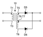
図9は、図1の変圧器10における巻線3a~4bの結線の他の一例を模式的に例示する図である。巻線3aの端部T2と巻線3bの端部T4とが互いに接続される。巻線4aの端部T6と巻線4bの端部T7とが互いに接続される。巻線3aの端部T1及び巻線3bの端部T3は、変圧器10の入力端子として使用され、巻線4aの端部T5及び巻線4bの端部T8は、変圧器10の出力端子として使用される。また、互いに接続された巻線4aの端部T6及び巻線4bの端部T7もまた、変圧器10の出力端子として使用される。図9の例では、巻線3a,3bを一次巻線として使用し、巻線4a,4bを二次巻線として使用する。
FIG. 9 is a diagram schematically illustrating another example of the connection of the
図9の例では、巻線3aの端部T1を「第1の端子」ともいい、巻線3bの端部T3を「第2の端子」ともいい、巻線4aの端部T5を「第3の端子」ともいい、巻線4bの端部T8を「第4の端子」ともいい、互いに接続された巻線4aの端部T6及び巻線4bの端部T7を「第5の端子」ともいう。 In the example of FIG. 9, the end portion T1 of the winding 3a is also referred to as a “first terminal”, the end portion T3 of the winding 3b is also referred to as a “second terminal”, and the end portion T5 of the winding 4a is referred to as a “second terminal”. The end T8 of the winding 4b is also referred to as a "fourth terminal", and the end T6 of the winding 4a and the end T7 of the winding 4b connected to each other are referred to as a "fifth terminal". Also called.
巻線3a,3bは、巻線3aの端部T1及び巻線3bの端部T3の間に電流が流れるときに巻線3a,3bにより主コア1のループに沿って同じ向きの磁束を発生するように、端部T1,T3の間に直列に接続される。巻線4a,4bは、巻線4aの端部T6から端部T5に電流が流れかつ巻線4bの端部T7から端部T8に電流が流れるときに(又は、巻線4aの端部T5から端部T6に電流が流れかつ巻線4bの端部T8から端部T7に電流が流れるときに)、巻線4a,4bにより主コア1のループに沿って同じ向きの磁束を発生するように互いに接続される。従って、巻線3aの端部T1及び巻線3bの端部T3の間に入力電流I1が流れるとき、主コア1のループに沿う磁束の変化に応じて、巻線4aの端部T6から端部T5に出力電流I2aが流れ、かつ、巻線4bの端部T7から端部T8に出力電流I2bが流れる(又は、巻線4aの端部T5から端部T6に出力電流I2aが流れ、かつ、巻線4bの端部T8から端部T7に出力電流I2bが流れる)。
The
図10は、図9の変圧器10を備えた電力変換装置の部分の一例を模式的に例示する回路図である。巻線4a,4bの巻数が互いに等しい場合、互いに接続された巻線4aの端部T6及び巻線4bの端部T7は二次巻線のセンタータップになる。この場合、巻線4a,4bの端部T5~T8には、ダイオードD5,D6を含む、センタータップを利用した整流回路を接続してもよい。
FIG. 10 is a circuit diagram schematically illustrating an example of a part of a power conversion device including the
図9及び図10の例では、巻線3a,3bの巻数は、互いに等しくても、互いに異なっていてもよい。また、図9及び図10の例では、巻線4a,4bの巻数は、前述のように、互いに等しく設定される。
In the example of FIGS. 9 and 10, the number of turns of the
図11は、図1の変圧器10における巻線3a~4bの結線のさらに他の一例を模式的に例示する図である。巻線3aの端部T2と巻線3bの端部T3とが互いに接続される。巻線4aの端部T6と巻線4bの端部T8とが互いに接続される。巻線4aの端部T5及び巻線4bの端部T7は、変圧器10の入力端子として使用され、巻線3aの端部T1及び巻線3bの端部T4は、変圧器10の出力端子として使用される。また、互いに接続された巻線3aの端部T2及び巻線3bの端部T3もまた、変圧器10の出力端子として使用される。図11の例では、巻線4a,4bを一次巻線として使用し、巻線3a,3bを二次巻線として使用する。
FIG. 11 is a diagram schematically illustrating still another example of the connection of the
図11の例では、巻線3aの端部T1を「第1の端子」ともいい、巻線3bの端部T4を「第2の端子」ともいい、巻線4aの端部T5を「第3の端子」ともいい、巻線4bの端部T7を「第4の端子」ともいい、互いに接続された巻線3aの端部T2及び巻線3bの端部T3を「第5の端子」ともいう。 In the example of FIG. 11, the end portion T1 of the winding 3a is also referred to as a “first terminal”, the end portion T4 of the winding 3b is also referred to as a “second terminal”, and the end portion T5 of the winding 4a is referred to as a “second terminal”. The end T7 of the winding 4b is also referred to as a "fourth terminal", and the end T2 of the winding 3a and the end T3 of the winding 3b connected to each other are referred to as a "fifth terminal". Also called.
巻線3a,3bは、巻線3aの端部T2から端部T1に電流が流れかつ巻線3bの端部T3から端部T4に電流が流れるときに(又は、巻線3aの端部T1から端部T2に電流が流れかつ巻線3bの端部T4から端部T3に電流が流れるときに)、巻線3a,3bにより主コア1のループに沿って同じ向きの磁束を発生するように互いに接続される。巻線4a,4bは、巻線4aの端部T5及び巻線4bの端部T7の間に電流が流れるときに巻線4a,4bにより主コア1のループに沿って同じ向きの磁束を発生するように、端部T5,T7の間に直列に接続される。従って、巻線4aの端部T5及び巻線4bの端部T7の間に入力電流I2が流れるとき、主コア1のループに沿う磁束の変化に応じて、巻線3aの端部T2から端部T1に出力電流I1aが流れ、かつ、巻線3bの端部T3から端部T4に出力電流I1bが流れる(又は、巻線3aの端部T1から端部T2に出力電流I1aが流れ、かつ、巻線3bの端部T4から端部T3に出力電流I1bが流れる)。
The
図12は、図11の変圧器10を備えた電力変換装置の部分の一例を模式的に例示する回路図である。巻線3a,3bの巻数が互いに等しい場合、互いに接続された巻線3aの端部T2及び巻線3bの端部T3は二次巻線のセンタータップになる。この場合、巻線3a,3bの端部T1~T4には、ダイオードD7,D8を含む、センタータップを利用した整流回路を接続してもよい。
FIG. 12 is a circuit diagram schematically illustrating an example of a part of a power conversion device including the
図11及び図12の例では、巻線3a,3bの巻数は、前述のように、互いに等しく設定される。また、図11及び図12の例では、巻線4a,4bの巻数は、互いに等しくても、互いに異なっていてもよい。
In the examples of FIGS. 11 and 12, the turns of the
図7~図12を参照して説明したように、本実施形態に係る変圧器10は、例えば、ダイオードブリッジを含む整流回路を備えた電力変換装置に適用可能であり、また、センタータップを利用した整流回路を備えた電力変換装置にも適用可能である。
As described with reference to FIGS. 7 to 12, the
[第1の実施形態の効果]
本実施形態に係る変圧器10は、バイパスコア2a,2bを通る磁束を発生することにより、大きな漏れインダクタンスを発生することができる。また、本実施形態に係る変圧器10は、巻線3a~4bから離れた位置に形成されたギャップGにおいて漏れ磁束を発生させることにより、漏れ磁束が巻線3a~4bに交差することを防止し、漏れ磁束が巻線3a~4bに交差することに起因する損失の増大を防止しながら、励磁インダクタンスを調整することができる。このように、本実施形態に係る変圧器10によれば、損失を増大させることなく、漏れインダクタンスを増大させることができる。
[Effect of the first embodiment]
The
また、本実施形態に係る変圧器10では、ギャップGの距離に応じて漏れ磁束の量を変化させることができる。また、本実施形態に係る変圧器10では、主コア1とバイパスコア2a,2bとの距離B2に応じて、及び/又は、バイパスコア2a,2bの長さに応じて、バイパスコア2a,2bを通る磁束の量を変化させ、従って、バイパスコア2a,2bを通る磁束によって生じる漏れインダクタンスを変化させることができる。
Further, in the
また、本実施形態に係る変圧器10では、主コア1の表面において一次巻線と二次巻線とを交互に配置するように巻回することにより、このように巻回しない場合よりも、巻線の近接効果による損失を低減することができる。
Further, in the
また、本実施形態に係る変圧器10では、巻線3a~4bは1周ごとに主コア1の表面に接するように(すなわち単層で)巻回されるので、巻線3a~4bによって生じた熱を良好に放熱することができる。巻線3a,3bの一部は主コア1及びバイパスコア2a,2bによって挟まれているが、このことは、巻線3a,3bの放熱を大幅にさまたげるものではない。
Further, in the
また、本実施形態に係る変圧器10では、前述のように各巻線3a~4bが主コア1の表面において単層で巻回されるが、主コア1のループに沿った複数の区間A1,A2に巻線3a~4bを巻回するので、主コア1の表面を有効に利用して巻線3a~4bの巻数を増やすことができる。
Further, in the
また、本実施形態に係る変圧器10は、その簡単な構成により、バイパスコア2a,2bを容易に組み込むことができる。
Further, the
特許文献1では、漏れ磁束が巻線に交差することによる損失を考慮せず、従って、このような漏れ磁束による損失を低減することができない。
また、特許文献1では、磁性体間隙片が一次巻線及び二次巻線の間にあるので、磁束が巻線にシールドされ、磁性体間隙片を通りにくい。よって、磁性体間隙片を備えていても、漏れインダクタンスを増加する効果は薄いと考えられる。
Further, in
また、特許文献1によれば、一次巻線は矩形のループの形状を有する鉄心の一辺の周りに巻回され、二次巻線は一次巻線の周りに巻回され、磁性体間隙片は一次巻線及び二次巻線の間に所定の角度幅ごとに挿入される。磁性体間隙片の長さは、一次巻線及び二次巻線の幅以下に制約される。従って、特許文献1では、漏れ磁束の量を変化させるために磁性体間隙片の長さを任意に変化させることはできない。
Further, according to
また、特許文献1によれば、前述のように、一次巻線は鉄心に巻回され、二次巻線は一次巻線の周りに巻回され、一次巻線及び二次巻線のそれぞれにおいて近接効果が生じると考えられる。特許文献1では、近接効果による損失を低減することができない。
Further, according to
また、特許文献1では、一次巻線は鉄心に巻回され、二次巻線は一次巻線の周りに巻回されるので、一次巻線及び二次巻線によって生じた熱を放熱しにくく、変圧器の温度が上昇しやすいと考えられる。
Further, in
特許文献2によれば、第1巻線及び第2巻線は第1磁性体の中足に巻回されるので、第1磁性体において、第1巻線及び第2巻線から離れた位置にギャップを形成することができない。従って、漏れ磁束が巻線に交差しにくいようにギャップを形成することができず、損失を増大させることなく漏れ磁束を増大させることは困難である。
According to
また、特許文献2によれば、第1巻線は第1磁性体に巻回され、第2巻線は第1巻線の周りに巻回され、第1巻線及び第2巻線のそれぞれにおいて近接効果が生じると考えられる。特許文献2では、近接効果による損失を低減することができない。
Further, according to
また、特許文献2によれば、第1巻線は第1磁性体に巻回され、第2巻線は第1巻線の周りに巻回されるので、第1巻線及び第2巻線によって生じた熱を放熱しにくく、変圧器の温度が上昇しやすいと考えられる。
Further, according to
一方、本実施形態に係る変圧器10では、漏れインダクタンスを増大することと、漏れ磁束が巻線に交差することによる損失の増大を防止することと、近接効果による損失を低減することとのすべてを達成するものである。これらの要件のすべてを達成することができる変圧器を想到することは容易ではない。
On the other hand, in the
[第1の実施形態の変形例]
次に、図13~図22を参照して、第1の実施形態の変形例について説明する。
[Modified example of the first embodiment]
Next, a modification of the first embodiment will be described with reference to FIGS. 13 to 22.
[第1の実施形態の第1の変形例]
図13は、第1の実施形態の第1の変形例に係る変圧器10Aの構成の一例を模式的に例示する正面図である。図13の変圧器10Aは、図1の主コア1に代えて、主コア1Aを備える。主コア1Aは、複数の主コア部分1Aa,1Abを含む。図1では、区間A3のギャップG及び区間A4のギャップGを区間A1,A2から等距離の位置に示したが、各ギャップGは、区間A3,A4において任意の位置に形成されてもよい。図13の例では、変圧器10Aは、区間A3において区間A2よりも区間A1に近接して形成された1つのギャップGと、区間A4において区間A1よりも区間A2に近接して形成された1つのギャップGとを備える。ギャップGは、ギャップGにおいて生じた漏れ磁束が実質的に巻線3a~4bに交差しないように、主コア1Aの区間A1及びA2の両方から離れた位置において主コア1Aのループに交差するように主コア1Aに形成されるのであれば、任意の位置に形成されてもよい。
[First Modification Example of First Embodiment]
FIG. 13 is a front view schematically illustrating an example of the configuration of the
[第1の実施形態の第2の変形例]
図14は、第1の実施形態の第2の変形例に係る変圧器10Bの構成の一例を模式的に例示する正面図である。図14の変圧器10Bは、図1の主コア1に代えて、主コア1Bを備える。主コア1Bは、複数の主コア部分1Ba,1Bbを含む。主コア1Bは、区間A3に形成された1つのギャップGを備える。本実施形態に係る変圧器は、所望の漏れ磁束の量に応じて、1つのギャップのみを備えてもよい。主コア1Bは、区間A3に形成されたギャップGに代えて、区間A4に形成された1つのギャップGを備えてもよい。
[Second variant of the first embodiment]
FIG. 14 is a front view schematically illustrating an example of the configuration of the
主コア1Bが1つのみのギャップGを備える場合、主コア1Bは、複数の主コア部分からなるのではなく、一体的に形成されてもよい。
When the
[第1の実施形態の第3の変形例]
図15は、第1の実施形態の第3の変形例に係る変圧器10Cの構成の一例を模式的に例示する正面図である。図15の変圧器10Cは、図1の主コア1に代えて、主コア1Cを備える。主コア1Cは、複数の主コア部分1Ca,1Cb,1Ccを含む。図15の例では、変圧器10Cは、区間A3に形成された複数のギャップGと、区間A4に形成された複数のギャップGとを備える。本実施形態に係る変圧器は、所望の漏れ磁束の量に応じて、区間A3,A4の少なくとも一方において、主コア1Cのループに交差するように主コア1Cに形成された複数のギャップGを備えてもよい。各ギャップGの距離が小さければ、漏れ磁束の漏れ出る範囲が小さくなり、巻線に交差しにくくなる。
[Third variant of the first embodiment]
FIG. 15 is a front view schematically illustrating an example of the configuration of the
区間A3,A4の一方において複数のギャップGを備え、区間A3,A4の他方において1つのギャップGを備えてもよい。また、区間A3,A4の一方において複数のギャップGを備え、区間A3,A4の他方においてギャップGを備えなくてもよい。 A plurality of gaps G may be provided in one of the sections A3 and A4, and one gap G may be provided in the other of the sections A3 and A4. Further, one of the sections A3 and A4 may have a plurality of gaps G, and the other of the sections A3 and A4 may not have a gap G.
[第1の実施形態の第4の変形例]
図16は、第1の実施形態の第4の変形例に係る変圧器10Dの構成の一例を模式的に例示する正面図である。図16の変圧器10Dでは、図1の巻線3b,4b及びバイパスコア2bを除去している。また、図16の変圧器10Dは、図1の主コア1に代えて、主コア1Dを備える。主コア1Dは、複数の主コア部分1Da,1Dbを含む。主コア部分1Daは、図1の主コア部分1aと同様に、例えばU字形に形成され、主コア部分1Dbは、例えばI字形に形成される。複数の主コア部分1Da,1Dbは、それらの間に少なくとも1つのギャップGを形成するように互いに機械的に連結される。主コア1Dは、その全体として、ループの形状を有する。
[Fourth variant of the first embodiment]
FIG. 16 is a front view schematically illustrating an example of the configuration of the
図16の変圧器10Dもまた、図1の変圧器10と同様に、バイパスコア2aを通る磁束を発生することにより、大きな漏れインダクタンスを発生することができる。また、図16の変圧器10Dもまた、図1の変圧器10と同様に、巻線3a,4aから離れた位置に形成されたギャップGにおいて漏れ磁束を発生させることにより、漏れ磁束が巻線3a,4aに交差することを防止し、漏れ磁束が巻線3a,4aに交差することに起因する損失の増大を防止しながら、励磁インダクタンスを調整することができる。このように、図16の変圧器10Dによれば、損失を増大させることなく、漏れインダクタンスを増大させることができる。
The
また、図16の変圧器10Dもまた、図1の変圧器10と同様に、ギャップGの距離に応じて漏れ磁束の量を変化させることができる。また、図16の変圧器10Dもまた、図1の変圧器10と同様に、主コア1D及びバイパスコア2aの距離に応じて、及び/又は、バイパスコア2aの長さに応じて、バイパスコア2aを通る磁束の量を変化させ、従って、バイパスコア2aを通る磁束によって生じる漏れインダクタンスを変化させることができる。
Further, the
また、図16の変圧器10Dもまた、図1の変圧器10と同様に、主コア1Dの表面において一次巻線と二次巻線とを交互に配置するように巻回することにより、このように巻回しない場合よりも、巻線の近接効果による損失を低減することができる。
Further, the
また、図16の変圧器10Dもまた、図1の変圧器10と同様に、巻線3a,4aは1周ごとに主コア1Dの表面に接するように(すなわち単層で)巻回されるので、巻線3a,4aによって生じた熱を良好に放熱することができる。
Further, the
また、図16の変圧器10Dもまた、図1の変圧器10と同様に、その簡単な構成により、バイパスコア2aを容易に組み込むことができる。
Further, the
[第1の実施形態の第5の変形例]
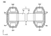
図17は、第1の実施形態の第5の変形例に係る変圧器10Eの構成の一例を模式的に例示する側面図である。図18は、図17の変圧器10Eの構成の一例を模式的に例示する上面図である。図17の変圧器10Eは、図1のバイパスコア2a,2bに代えて、バイパスコア2a1~2b2を備える。
[Fifth variant of the first embodiment]
FIG. 17 is a side view schematically illustrating an example of the configuration of the
バイパスコア2a1,2a2は、巻線3aを巻回した主コア1の区間に沿って、かつ、巻線3aの外側に設けられる。バイパスコア2b1,2b2は、巻線3bを巻回した主コア1の区間に沿って、かつ、巻線3bの外側に設けられる。巻線4aは、巻線3aを巻回した主コア1の区間において主コア1及びバイパスコア2a1,2a2に巻回される。巻線4bは、巻線3bを巻回した主コア1の区間において主コア1及びバイパスコア2b1,2b2に巻回される。
The bypass cores 2a1 and 2a2 are provided along the section of the
図18の例では、バイパスコア2a1,2a2を「第1のバイパスコア」ともいい、バイパスコア2b1,2b2を「第2のバイパスコア」ともいう。 In the example of FIG. 18, the bypass cores 2a1 and 2a2 are also referred to as a "first bypass core", and the bypass cores 2b1 and 2b2 are also referred to as a "second bypass core".
図17の変圧器10Eは、巻線3a,4aに関連して2つのバイパスコア2a1,2a2を備え、巻線3b,4bに関連して2つのバイパスコア2b1,2b2を備える。これにより、図1のように1つずつのバイパスコア2a,2bを備える場合よりも、バイパスコア2a1,2a2,2b1,2b2を通る磁束の量を増大することができる。
The
巻線3a,4aに関連して3つ以上のバイパスコアを備え、巻線3b,4bに関連して3つ以上のバイパスコアを備えてもよい。
Three or more bypass cores may be provided in relation to the
[第1の実施形態の第6の変形例]
図19は、第1の実施形態の第6の変形例に係る変圧器10Fの構成の一例を模式的に例示する正面図である。図19の変圧器10Fは、図1のバイパスコア2a,2bに代えて、バイパスコア2Fa,2Fbを備える。
[Sixth modification of the first embodiment]
FIG. 19 is a front view schematically illustrating an example of the configuration of the
バイパスコア2Fa,2Fbは、主コア1に沿って延在し、両端において主コア1に向かって屈曲する。
The bypass cores 2Fa and 2Fb extend along the
図19の例では、バイパスコア2Faを「第1のバイパスコア」ともいい、バイパスコア2Fbを「第2のバイパスコア」ともいう。 In the example of FIG. 19, the bypass core 2Fa is also referred to as a “first bypass core”, and the bypass core 2Fb is also referred to as a “second bypass core”.
主コアとバイパスコアとの距離が十分に小さくない場合、バイパスコア2Fa,2Fbを通る磁束は生じにくくなる。図19の変圧器10Fによれば、各バイパスコア2Fa,2Fbの両端を屈曲することにより、主コア1と各バイパスコア2Fa,2Fbとの距離が短くなる。これにより、図1の変圧器10の場合よりも、磁束がバイパスコア2Fa,2Fbを通りやすくなり、バイパスコア2Fa,2Fbを通る磁束の量を増大することができる。従って、図1の変圧器10の場合よりも、漏れインダクタンスを増大させることができる。
If the distance between the main core and the bypass core is not sufficiently small, magnetic flux passing through the bypass cores 2Fa and 2Fb is unlikely to occur. According to the
[第1の実施形態の第7の変形例]
図20は、第1の実施形態の第7の変形例に係る変圧器10Gの構成の一例を模式的に例示する正面図である。図20の変圧器10Gは、図1のバイパスコア2a,2bに代えて、バイパスコア2Ga,2Gbを備える。
[7th modification of the 1st embodiment]
FIG. 20 is a front view schematically illustrating an example of the configuration of the
バイパスコア2Ga,2Gbは、主コア1に沿って延在し、両端において主コア1に沿って屈曲する。
The bypass cores 2Ga and 2Gb extend along the
図20の例では、バイパスコア2Gaを「第1のバイパスコア」ともいい、バイパスコア2Gbを「第2のバイパスコア」ともいう。 In the example of FIG. 20, the bypass core 2Ga is also referred to as a “first bypass core”, and the bypass core 2Gb is also referred to as a “second bypass core”.
前述のように、主コアとバイパスコアとが互いに対向する領域の面積が増大するほど、バイパスコア2Ga,2Gbを通る磁束の量が増大する。図20の変圧器20Gによれば、各バイパスコア2Ga,2Gbの両端を屈曲することにより、主コア1とバイパスコア2Ga,2Gbとが互いに対向する領域の面積が増大する。これにより、図1の変圧器10の場合よりも、磁束がバイパスコア2Ga,2Gbを通りやすくなり、バイパスコア2Ga,2Gbを通る磁束の量を増大することができる。従って、図1の変圧器10の場合よりも、漏れインダクタンスを増大させることができる。
As described above, as the area of the region where the main core and the bypass core face each other increases, the amount of magnetic flux passing through the bypass cores 2Ga and 2Gb increases. According to the transformer 20G of FIG. 20, by bending both ends of the bypass cores 2Ga and 2Gb, the area of the region where the
[第1の実施形態の第8の変形例]
図21は、第1の実施形態の第8の変形例に係る変圧器10Hの構成の一例を模式的に例示する側面図である。図22は、図21の変圧器10Hの構成の一例を模式的に例示する上面図である。図21の変圧器10Hは、図1のバイパスコア2a,2bに代えて、バイパスコア2Ha1~2Hb2を備える。変圧器10Hは、第5の変形例と第7の変形例との組み合わせに相当する。
[Eighth variant of the first embodiment]
FIG. 21 is a side view schematically illustrating an example of the configuration of the
バイパスコア2Ha1,2Ha2は、巻線3aを巻回した主コア1の区間に沿って、かつ、巻線3aの外側に設けられる。バイパスコア2Hb1,2Hb2は、巻線3bを巻回した主コア1の区間に沿って、かつ、巻線3bの外側に設けられる。巻線4aは、巻線3aを巻回した主コア1の区間において主コア1及びバイパスコア2Ha1,2Ha2に巻回される。巻線4bは、巻線3bを巻回した主コア1の区間において主コア1及びバイパスコア2Hb1,2Hb2に巻回される。バイパスコア2Ha1~2Hb2は、主コア1に沿って延在し、両端において主コア1に沿って屈曲する。
The bypass cores 2Ha1 and 2Ha2 are provided along the section of the
図21に示すように、各バイパスコア2Ha1,2Ha2は、その両端において互いに接してもよい。同様に、各バイパスコア2Hb1,2Hb2は、その両端において互いに接してもよい。 As shown in FIG. 21, the bypass cores 2Ha1 and 2Ha2 may be in contact with each other at both ends thereof. Similarly, the bypass cores 2Hb1 and 2Hb2 may touch each other at both ends thereof.
図21の例では、バイパスコア2Ha1,2Ha2を「第1のバイパスコア」ともいい、バイパスコア2Hb1,2Hb2を「第2のバイパスコア」ともいう。 In the example of FIG. 21, the bypass cores 2Ha1 and 2Ha2 are also referred to as "first bypass cores", and the bypass cores 2Hb1 and 2Hb2 are also referred to as "second bypass cores".
図21の変圧器20Hによれば、図17の変圧器10Eの場合よりも、また、図20の変圧器10Gの場合よりも、漏れインダクタンスを増大することができる。
According to the transformer 20H of FIG. 21, the leakage inductance can be increased as compared with the case of the
[第2の実施形態]
図23~図24を参照して、第2の実施形態に係る電力変換装置について説明する。
[Second Embodiment]
The power conversion device according to the second embodiment will be described with reference to FIGS. 23 to 24.
[第2の実施形態の構成例]
図23は、第2の実施形態に係る電力変換装置の一例を模式的に例示する回路図である。図23の電力変換装置は、電流共振型のDC-DCコンバータの一例を示す。図23の電力変換装置は、変圧器10、直流電源21、駆動回路22、負荷23、キャパシタC1,C2、ダイオードD5,D6、及びスイッチ素子Q1,Q2を備える。
[Structure example of the second embodiment]
FIG. 23 is a circuit diagram schematically illustrating an example of the power conversion device according to the second embodiment. The power conversion device of FIG. 23 shows an example of a current resonance type DC-DC converter. The power conversion device of FIG. 23 includes a
直流電源21は、直流の入力電圧Vinを供給する。スイッチ素子Q1,Q2は、駆動回路22の制御下で動作する。図23の変圧器10は、例えば、図1の変圧器10と同様に構成される。変圧器10は、等価的に、インダクタLr,Lmを含む。インダクタLr,Lm及びキャパシタC1は、共振回路を構成する。変圧器10は、図9及び図10を参照して説明したように、ダイオードD5,D6を含む、センタータップを利用した整流回路に接続される。整流された電圧はキャパシタC2によって平滑化され、平滑化された出力電圧Vout及び出力電流Ioutは負荷23に供給される。
The
図24は、図23の電力変換装置の共振回路の動作の一例を模式的に例示するグラフである。図24のグラフは、図23のインダクタLr,Lm及びキャパシタC1を含む共振回路の周波数特性であって、インダクタLrのインダクタンスが小さいとき及び大きいときの周波数特性を示す。図23の電力変換装置では、スイッチ素子Q1,Q2のスイッチング周波数を下げることで、共振回路の利得が増大する。この制御法により、入力電圧Vinの変動に対処し、また、負荷23の変動に対処することができる。しかしながら、図24によれば、インダクタLrのインダクタンスを調節することで、スイッチング周波数を変化させることなく共振回路の最大利得が増加することがわかる。周波数f1では、インダクタLrのインダクタンスが大きいときの利得が、インダクタLrのインダクタンスが小さいときの利得よりも高くなる。一方、周波数f2では、インダクタLrのインダクタンスが小さいときの利得が、インダクタLrのインダクタンスが大きいときの利得よりも高くなる。これにより、スイッチング周波数を大幅に高くしたり大幅に低下させたりすることなく、入力電圧及び負荷のワイドレンジ化を達成することができる。
FIG. 24 is a graph schematically illustrating an example of the operation of the resonance circuit of the power conversion device of FIG. 23. The graph of FIG. 24 shows the frequency characteristics of the resonant circuit including the inductor Lr, Lm and the capacitor C1 of FIG. 23, and shows the frequency characteristics when the inductance of the inductor Lr is small and large. In the power conversion device of FIG. 23, the gain of the resonance circuit is increased by lowering the switching frequency of the switch elements Q1 and Q2. By this control method, it is possible to deal with the fluctuation of the input voltage Vin and also to deal with the fluctuation of the
本開示の実施形態に係る変圧器10によれば、変圧器10の漏れインダクタンスがインダクタLrとして作用する。従って、図23の電力変換装置では、インダクタLrの部品を追加することなく、共振回路のインダクタンスを調節することができる。追加のインダクタLrが不要であることにより、電力変換装置の電力密度を増大することができる。
According to the
本実施形態に係る電力変換装置によれば、変圧器10を備えたことにより、変圧器10の損失を増大させることなく、励磁インダクタンスを調整することができ、変圧器10の漏れインダクタンスを増大させることができる。また、変圧器10の漏れインダクタンスが共振することにより、電力変換装置の利得を増大することができる。従って、本実施形態によれば、高い電力密度を有する電力変換装置を実現することができる。
According to the power conversion device according to the present embodiment, by providing the
本実施形態に係る電力変換装置では、図1の変圧器10に代えて、他の変形例に係る変圧器10A~10Hを用いてもよい。
In the power conversion device according to the present embodiment, the
本開示の実施形態によれば、図23に示す回路に限らず、変圧器を含む他の電力変換装置を提供してもよい。 According to the embodiment of the present disclosure, not only the circuit shown in FIG. 23 but also other power conversion devices including a transformer may be provided.
本開示の実施形態によれば、電力変換装置に限らず、変圧器を含む他の電子回路を提供してもよい。 According to the embodiment of the present disclosure, not only the power conversion device but also other electronic circuits including a transformer may be provided.
[他の変形例]
以上、本開示の実施形態を詳細に説明してきたが、前述までの説明はあらゆる点において本開示の例示に過ぎない。本開示の範囲を逸脱することなく種々の改良や変形を行うことができることは言うまでもない。例えば、以下のような変更が可能である。なお、以下では、上記実施形態と同様の構成要素に関しては同様の符号を用い、上記実施形態と同様の点については、適宜説明を省略した。
[Other variants]
Although the embodiments of the present disclosure have been described in detail above, the above description is merely an example of the present disclosure in all respects. Needless to say, various improvements and modifications can be made without departing from the scope of the present disclosure. For example, the following changes can be made. In the following, the same reference numerals will be used for the same components as those in the above embodiment, and the same points as in the above embodiment will be omitted as appropriate.
上述した各実施形態及び各変形例は、任意に組み合わされてもよい。 Each of the above-described embodiments and modifications may be arbitrarily combined.
本明細書で説明した実施形態は、あらゆる点において本開示の例示に過ぎない。本開示の範囲を逸脱することなく種々の改良や変形を行うことができることは言うまでもない。つまり、本開示の実施にあたって、実施形態に応じた具体的構成が適宜採用されてもよい。 The embodiments described herein are merely exemplary of the present disclosure in all respects. Needless to say, various improvements and modifications can be made without departing from the scope of the present disclosure. That is, in carrying out the present disclosure, a specific configuration according to the embodiment may be appropriately adopted.
図1他では、矩形の主コアを示したが、これに限定されない。主コアは矩形以外の形状、例えばリング形状を有してもよい。 In FIG. 1 and others, a rectangular main core is shown, but the present invention is not limited to this. The main core may have a shape other than a rectangle, for example, a ring shape.
図1他では、主コアが2つの主コア部分からなる場合について説明したが、これに限定されない。主コアは3つ以上の主コア部分から構成されてもよい。 In FIG. 1 and others, the case where the main core consists of two main core portions has been described, but the present invention is not limited to this. The main core may be composed of three or more main core portions.
図1他では、巻線3a~4bが2つの区間A1,A2に巻回される場合について説明したが、これに限定されない。巻線3a~4bは、主コアのループのうちの互いに離れた3つ以上の区間において主コアに巻回されてもよく、図16に示すように、1つの区間において主コアに巻回されてもよい。巻線3a~4bを巻回した区間の個数に応じて、3つ以上のバイパスコアが設けられてもよく、図16に示すように、1つのバイパスコアが設けられてもよい。
In FIG. 1 and others, the case where the
バイパスコアの形状及び個数は、主コアからバイパスコアを介して再び主コアに戻る磁束(すなわち、バイパスコアを通る磁束)を発生するのであれば、図1、図17~図22等に示すものに限定されず、他の任意の形状及び個数であってもよい。 The shape and number of the bypass cores are shown in FIGS. 1, 17 to 22, etc., if a magnetic flux that returns from the main core to the main core via the bypass core (that is, a magnetic flux that passes through the bypass core) is generated. It is not limited to, and may be any other shape and number.
[まとめ]
本開示の各側面に係る変圧器及び電力変換装置は、以下のように表現されてもよい。
[summary]
The transformer and the power conversion device according to each aspect of the present disclosure may be expressed as follows.
本開示の第1の側面に係る変圧器(10,10A~10H)は、
ループの形状を有する主コア(1,1A~1C)と、
前記主コア(1,1A~1C)のループのうちの第1の区間(A1)において前記主コア(1,1A~1C)に巻回された第1の巻線(3a)と、
前記主コア(1,1A~1C)のループのうちの前記第1の区間(A1)から離れた第2の区間(A2)において前記主コア(1,1A~1C)に巻回された第2の巻線(3b)と、
前記主コア(1,1A~1C)の前記第1の区間(A1)に沿って、かつ、前記第1の巻線(3a)の外側に設けられた少なくとも1つの第1のバイパスコア(2a)と、
前記主コア(1,1A~1C)の前記第1の区間(A1)において前記主コア(1,1A~1C)及び前記第1のバイパスコア(2a)に巻回された第3の巻線(4a)と、
前記主コア(1,1A~1C)の前記第2の区間(A2)に沿って、かつ、前記第2の巻線(3b)の外側に設けられた少なくとも1つの第2のバイパスコア(2b)と、
前記主コア(1,1A~1C)の前記第2の区間(A2)において前記主コア(1,1A~1C)及び前記第2のバイパスコア(2b)に巻回された第4の巻線(4b)と、
前記主コア(1,1A~1C)の前記第1及び第2の区間(A1,A2)の両方から離れた位置において前記主コア(1,1A~1C)のループに交差するように前記主コア(1,1A~1C)に形成された少なくとも1つのギャップ(G)とを備える。
The transformer (10, 10A to 10H) according to the first aspect of the present disclosure is
The main core (1,1A-1C) having the shape of a loop,
The first winding (3a) wound around the main core (1,1A to 1C) in the first section (A1) of the loop of the main core (1,1A to 1C).
The second section (A2) away from the first section (A1) of the loop of the main core (1,1A to 1C) is wound around the main core (1,1A to 1C). 2 windings (3b) and
At least one first bypass core (2a) provided along the first section (A1) of the main core (1,1A-1C) and outside the first winding (3a). )When,
A third winding wound around the main core (1,1A-1C) and the first bypass core (2a) in the first section (A1) of the main core (1,1A to 1C). (4a) and
At least one second bypass core (2b) provided along the second section (A2) of the main core (1,1A-1C) and outside the second winding (3b). )When,
A fourth winding wound around the main core (1,1A-1C) and the second bypass core (2b) in the second section (A2) of the main core (1,1A-1C). (4b) and
The main core (1,1A-1C) so as to intersect the loop of the main core (1,1A-1C) at a position away from both the first and second sections (A1, A2) of the main core (1,1A-1C). It comprises at least one gap (G) formed in the core (1,1A-1C).
本開示の第2の側面に係る変圧器(10,10A~10H)によれば、第1の側面に係る変圧器において、
前記第1のバイパスコア(2a)は、前記第1の区間(A1)の長さを超える長さにわたって延在し、
前記第2のバイパスコア(2b)は、前記第2の区間(A2)の長さを超える長さにわたって延在する。
According to the transformer (10, 10A to 10H) according to the second aspect of the present disclosure, in the transformer according to the first aspect,
The first bypass core (2a) extends over a length exceeding the length of the first section (A1).
The second bypass core (2b) extends over a length that exceeds the length of the second section (A2).
本開示の第3の側面に係る変圧器(10,10A~10H)によれば、第2の側面に係る変圧器において、
前記第1及び第2のバイパスコア(2a,2b)は、前記主コア(1,1A~1C)に沿って延在し、両端において前記主コア(1,1A~1C)に向かって又は前記主コア(1,1A~1C)に沿って屈曲する。
According to the transformer (10, 10A to 10H) according to the third aspect of the present disclosure, in the transformer according to the second aspect,
The first and second bypass cores (2a, 2b) extend along the main core (1,1A-1C) and at both ends towards or above the main core (1,1A-1C). It bends along the main core (1,1A-1C).
本開示の第4の側面に係る変圧器(10,10A~10H)は、第1~第3のうちの1つの側面に係る変圧器において、
複数の第1のバイパスコア(2a1,2a2;2Ha1,2Ha2)及び複数の第2のバイパスコア(2b1,2b2;2Hb1,2Hb2)を備える。
The transformer (10, 10A to 10H) according to the fourth aspect of the present disclosure is the transformer according to one of the first to third aspects.
A plurality of first bypass cores (2a1,2a2; 2Ha1,2Ha2) and a plurality of second bypass cores (2b1,2b2; 2Hb1,2Hb2) are provided.
本開示の第5の側面に係る変圧器(10,10A~10H)によれば、第1~第4のうちの1つの側面に係る変圧器において、
前記第1及び第3の巻線(3a,4a)はそれぞれ、1周ごとに前記主コア(1,1A~1C)の表面に接するように、かつ、前記主コア(1,1A~1C)の表面において交互に配置されるように巻回され、
前記第2及び第4の巻線(3b,4b)はそれぞれ、1周ごとに前記主コア(1,1A~1C)の表面に接するように、かつ、前記主コア(1,1A~1C)の表面において交互に配置されるように巻回される。
According to the transformer (10, 10A to 10H) according to the fifth aspect of the present disclosure, in the transformer according to one of the first to fourth aspects,
The first and third windings (3a, 4a) are in contact with the surface of the main core (1,1A to 1C) every turn, and the main core (1,1A to 1C), respectively. Wrapped so that they are alternately placed on the surface of the
The second and fourth windings (3b, 4b) are in contact with the surface of the main core (1,1A to 1C) every turn, and the main core (1,1A to 1C), respectively. It is wound so as to be alternately arranged on the surface of the.
本開示の第6の側面に係る変圧器(10,10A~10H)は、第1~第5のうちの1つの側面に係る変圧器において、
前記主コア(1,1A~1C)のループのうちの前記第1の区間(A1)の一端と前記第2の区間(A2)の一端との間の第3の区間(A3)において、前記主コア(1,1A~1C)のループに交差するように前記主コア(1,1A~1C)に形成された少なくとも1つのギャップ(G)と、
前記主コア(1,1A~1C)のループのうちの前記第1の区間(A1)の他端と前記第2の区間(A2)の他端との間の第4の区間(A4)において、前記主コア(1,1A~1C)のループに交差するように前記主コア(1,1A~1C)に形成された少なくとも1つのギャップ(G)とを備える。
The transformer (10, 10A to 10H) according to the sixth aspect of the present disclosure is the transformer according to one of the first to fifth aspects.
In the third section (A3) between one end of the first section (A1) and one end of the second section (A2) in the loop of the main core (1,1A to 1C). With at least one gap (G) formed in the main core (1,1A-1C) so as to intersect the loop of the main core (1,1A-1C).
In the fourth section (A4) between the other end of the first section (A1) and the other end of the second section (A2) in the loop of the main core (1,1A to 1C). , With at least one gap (G) formed in the main core (1,1A-1C) so as to intersect the loop of the main core (1,1A-1C).
本開示の第7の側面に係る変圧器(10,10A~10H)は、第6の側面に係る変圧器において、
前記第3及び第4の区間(A3,A4)のうちの少なくとも一方において、前記主コア(1C)のループに交差するように前記主コア(1C)に形成された複数のギャップ(G)を備える。
The transformer (10, 10A to 10H) according to the seventh aspect of the present disclosure is the transformer according to the sixth aspect.
A plurality of gaps (G) formed in the main core (1C) so as to intersect the loop of the main core (1C) in at least one of the third and fourth sections (A3, A4). Be prepared.
本開示の第8の側面に係る変圧器(10,10A~10H)は、第1~第7のうちの1つの側面に係る変圧器において、
前記変圧器は第1~第4の端子を備え、
前記第1及び第2の巻線(3a,3b)は、前記第1及び第2の端子の間に電流が流れるときに前記第1及び第2の巻線(3a,3b)により前記主コア(1,1A~1C)のループに沿って同じ向きの磁束を発生するように、前記第1及び第2の端子の間に直列に接続され、
前記第3及び第4の巻線(4a,4b)は、前記第3及び第4の端子の間に電流が流れるときに前記第3及び第4の巻線(4a,4b)により前記主コア(1,1A~1C)のループに沿って同じ向きの磁束を発生するように、前記第3及び第4の端子の間に直列に接続される。
The transformer (10, 10A to 10H) according to the eighth aspect of the present disclosure is the transformer according to one aspect of the first to seventh aspects.
The transformer has first to fourth terminals and has
The first and second windings (3a, 3b) are the main core by the first and second windings (3a, 3b) when a current flows between the first and second terminals. It is connected in series between the first and second terminals so as to generate magnetic fluxes in the same direction along the loop (1,1A to 1C).
The third and fourth windings (4a, 4b) are the main core by the third and fourth windings (4a, 4b) when a current flows between the third and fourth terminals. It is connected in series between the third and fourth terminals so as to generate magnetic fluxes in the same direction along the loop (1, 1A to 1C).
本開示の第9の側面に係る変圧器(10,10A~10H)は、第1~第7のうちの1つの側面に係る変圧器において、
前記変圧器は第1~第5の端子を備え、
前記第1及び第2の巻線(3a,3b)は、前記第1及び第2の端子の間に電流が流れるときに前記第1及び第2の巻線(3a,3b)により前記主コア(1,1A~1C)のループに沿って同じ向きの磁束を発生するように、前記第1及び第2の端子の間に直列に接続され、
前記第3の巻線(4a)は、前記第3及び第5の端子の間に接続され、
前記第4の巻線(4b)は、前記第4及び第5の端子の間に接続され、
前記第3及び第4の巻線(4a,4b)は、前記第5の端子から前記第3及び第4の端子にそれぞれ電流が流れるときに前記第3及び第4の巻線(4a,4b)により前記主コア(1,1A~1C)のループに沿って同じ向きの磁束を発生するように互いに接続される。
The transformer (10, 10A to 10H) according to the ninth aspect of the present disclosure is the transformer according to one of the first to seventh aspects.
The transformer has first to fifth terminals and has
The first and second windings (3a, 3b) are the main core by the first and second windings (3a, 3b) when a current flows between the first and second terminals. It is connected in series between the first and second terminals so as to generate magnetic fluxes in the same direction along the loop (1,1A to 1C).
The third winding (4a) is connected between the third and fifth terminals.
The fourth winding (4b) is connected between the fourth and fifth terminals.
The third and fourth windings (4a, 4b) are the third and fourth windings (4a, 4b) when a current flows from the fifth terminal to the third and fourth terminals, respectively. ) Are connected to each other so as to generate magnetic fluxes in the same direction along the loop of the main core (1,1A to 1C).
本開示の第10の側面に係る変圧器(10,10A~10H)は、第1~第7のうちの1つの側面に係る変圧器において、
前記変圧器は第1~第5の端子を備え、
前記第1の巻線(3a)は、前記第1及び第5の端子の間に接続され、
前記第2の巻線(3b)は、前記第2及び第5の端子の間に接続され、
前記第1及び第2の巻線(3a,3b)は、前記第5の端子から前記第1及び第2の端子にそれぞれ電流が流れるときに前記第1及び第2の巻線(3a,3b)により前記主コア(1,1A~1C)のループに沿って同じ向きの磁束を発生するように互いに接続され、
前記第3及び第4の巻線(4a,4b)は、前記第3及び第4の端子の間に電流が流れるときに前記第3及び第4の巻線(4a,4b)により前記主コア(1,1A~1C)のループに沿って同じ向きの磁束を発生するように、前記第3及び第4の端子の間に直列に接続される。
The transformer (10, 10A to 10H) according to the tenth aspect of the present disclosure is the transformer according to one of the first to seventh aspects.
The transformer has first to fifth terminals and has
The first winding (3a) is connected between the first and fifth terminals.
The second winding (3b) is connected between the second and fifth terminals.
The first and second windings (3a, 3b) are the first and second windings (3a, 3b) when a current flows from the fifth terminal to the first and second terminals, respectively. ) Connected to each other so as to generate magnetic fluxes in the same direction along the loop of the main core (1,1A to 1C).
The third and fourth windings (4a, 4b) are the main core by the third and fourth windings (4a, 4b) when a current flows between the third and fourth terminals. It is connected in series between the third and fourth terminals so as to generate magnetic fluxes in the same direction along the loop (1, 1A to 1C).
本開示の第11の側面に係る電力変換装置は、第1~第10のうちの1つの側面に係る変圧器(10,10A~10H)を備える。 The power conversion device according to the eleventh aspect of the present disclosure includes a transformer (10, 10A to 10H) according to one aspect of the first to tenth aspects.
本開示の各側面に係る変圧器は、例えば、高い電力密度を有する電力変換装置に適用可能である。 The transformer according to each aspect of the present disclosure is applicable to, for example, a power conversion device having a high power density.
1,1A~1D…主コア、
1a,1b,1Aa~1Da,1Ab~1Db,1Cc…主コア部分、
2a,2b,2a1~2b2,2Fa,2Fb,2Ga,2Gb,2Ha1~2Hb2…バイパスコア、
3a,3b,4a,4b…巻線、
5,6…スペーサ、
10,10A~10H…変圧器、
21…直流電源、
22…駆動回路、
23…負荷、
C1,C2…キャパシタ、
D1~D8…ダイオード、
G…ギャップ、
Q1,Q2…スイッチ素子。
1,1A-1D ... Main core,
1a, 1b, 1Aa to 1Da, 1Ab to 1Db, 1Cc ... Main core part,
2a, 2b, 2a1-2b2, 2Fa, 2Fb, 2Ga, 2Gb, 2Ha1-2Hb2 ... Bypass core,
3a, 3b, 4a, 4b ... Winding,
5, 6 ... Spacer,
10,10A-10H ... Transformer,
21 ... DC power supply,
22 ... Drive circuit,
23 ... Load,
C1, C2 ... Capacitor,
D1 to D8 ... Diode,
G ... Gap,
Q1, Q2 ... Switch element.
Claims (11)
前記主コアのループのうちの第1の区間において前記主コアに巻回された第1の巻線と、
前記主コアのループのうちの前記第1の区間から離れた第2の区間において前記主コアに巻回された第2の巻線と、
前記主コアの前記第1の区間に沿って、かつ、前記第1の巻線の外側に設けられた少なくとも1つの第1のバイパスコアと、
前記主コアの前記第1の区間において前記主コア及び前記第1のバイパスコアに巻回された第3の巻線と、
前記主コアの前記第2の区間に沿って、かつ、前記第2の巻線の外側に設けられた少なくとも1つの第2のバイパスコアと、
前記主コアの前記第2の区間において前記主コア及び前記第2のバイパスコアに巻回された第4の巻線と、
前記主コアの前記第1及び第2の区間の両方から離れた位置において前記主コアのループに交差するように前記主コアに形成された少なくとも1つのギャップとを備えた、
変圧器。 The main core with the shape of a loop and
With the first winding wound around the main core in the first section of the loop of the main core,
A second winding wound around the main core in a second section of the loop of the main core away from the first section,
With at least one first bypass core provided along the first section of the main core and outside the first winding.
A third winding wound around the main core and the first bypass core in the first section of the main core.
With at least one second bypass core provided along the second section of the main core and outside the second winding.
A fourth winding wound around the main core and the second bypass core in the second section of the main core.
It comprises at least one gap formed in the main core so as to intersect the loop of the main core at a position away from both the first and second sections of the main core.
Transformer.
前記第2のバイパスコアは、前記第2の区間の長さを超える長さにわたって延在する、
請求項1記載の変圧器。 The first bypass core extends over a length that exceeds the length of the first section.
The second bypass core extends over a length that exceeds the length of the second section.
The transformer according to claim 1.
請求項2記載の変圧器。 The first and second bypass cores extend along the main core and bend towards or along the main core at both ends.
The transformer according to claim 2.
請求項1~3のうちの1つに記載の変圧器。 A plurality of first bypass cores and a plurality of second bypass cores.
The transformer according to any one of claims 1 to 3.
前記第2及び第4の巻線はそれぞれ、1周ごとに前記主コアの表面に接するように、かつ、前記主コアの表面において交互に配置されるように巻回された、
請求項1~4のうちの1つに記載の変圧器。 The first and third windings are wound so as to be in contact with the surface of the main core and alternately arranged on the surface of the main core every turn.
The second and fourth windings were wound so as to be in contact with the surface of the main core and to be alternately arranged on the surface of the main core every turn.
The transformer according to any one of claims 1 to 4.
前記主コアのループのうちの前記第1の区間の他端と前記第2の区間の他端との間の第4の区間において、前記主コアのループに交差するように前記主コアに形成された少なくとも1つのギャップとを備えた、
請求項1~5のうちの1つに記載の変圧器。 In the third section between one end of the first section and one end of the second section of the loop of the main core, the main core is formed so as to intersect the loop of the main core. With at least one gap,
Formed on the main core so as to intersect the loop of the main core in the fourth section between the other end of the first section and the other end of the second section of the loop of the main core. With at least one gap made,
The transformer according to any one of claims 1 to 5.
請求項6記載の変圧器。 At least one of the third and fourth sections comprises a plurality of gaps formed in the main core so as to intersect the loop of the main core.
The transformer according to claim 6.
前記第1及び第2の巻線は、前記第1及び第2の端子の間に電流が流れるときに前記第1及び第2の巻線により前記主コアのループに沿って同じ向きの磁束を発生するように、前記第1及び第2の端子の間に直列に接続され、
前記第3及び第4の巻線は、前記第3及び第4の端子の間に電流が流れるときに前記第3及び第4の巻線により前記主コアのループに沿って同じ向きの磁束を発生するように、前記第3及び第4の端子の間に直列に接続された、
請求項1~7のうちの1つに記載の変圧器。 The transformer has first to fourth terminals and has
The first and second windings exert a magnetic flux in the same direction along the loop of the main core by the first and second windings when a current flows between the first and second terminals. Connected in series between the first and second terminals so as to occur
The third and fourth windings exert a magnetic flux in the same direction along the loop of the main core by the third and fourth windings when a current flows between the third and fourth terminals. Connected in series between the third and fourth terminals so as to occur.
The transformer according to any one of claims 1 to 7.
前記第1及び第2の巻線は、前記第1及び第2の端子の間に電流が流れるときに前記第1及び第2の巻線により前記主コアのループに沿って同じ向きの磁束を発生するように、前記第1及び第2の端子の間に直列に接続され、
前記第3の巻線は、前記第3及び第5の端子の間に接続され、
前記第4の巻線は、前記第4及び第5の端子の間に接続され、
前記第3及び第4の巻線は、前記第5の端子から前記第3及び第4の端子にそれぞれ電流が流れるときに前記第3及び第4の巻線により前記主コアのループに沿って同じ向きの磁束を発生するように互いに接続された、
請求項1~7のうちの1つに記載の変圧器。 The transformer has first to fifth terminals and has
The first and second windings exert a magnetic flux in the same direction along the loop of the main core by the first and second windings when a current flows between the first and second terminals. Connected in series between the first and second terminals so as to occur
The third winding is connected between the third and fifth terminals.
The fourth winding is connected between the fourth and fifth terminals.
The third and fourth windings are along the loop of the main core by the third and fourth windings as current flows from the fifth terminal to the third and fourth terminals, respectively. Connected to each other to generate magnetic fluxes in the same direction,
The transformer according to any one of claims 1 to 7.
前記第1の巻線は、前記第1及び第5の端子の間に接続され、
前記第2の巻線は、前記第2及び第5の端子の間に接続され、
前記第1及び第2の巻線は、前記第5の端子から前記第1及び第2の端子にそれぞれ電流が流れるときに前記第1及び第2の巻線により前記主コアのループに沿って同じ向きの磁束を発生するように互いに接続され、
前記第3及び第4の巻線は、前記第3及び第4の端子の間に電流が流れるときに前記第3及び第4の巻線により前記主コアのループに沿って同じ向きの磁束を発生するように、前記第3及び第4の端子の間に直列に接続された、
請求項1~7のうちの1つに記載の変圧器。 The transformer has first to fifth terminals and has
The first winding is connected between the first and fifth terminals.
The second winding is connected between the second and fifth terminals.
The first and second windings are along the loop of the main core by the first and second windings as current flows from the fifth terminal to the first and second terminals, respectively. Connected to each other to generate magnetic flux in the same direction,
The third and fourth windings exert a magnetic flux in the same direction along the loop of the main core by the third and fourth windings when a current flows between the third and fourth terminals. Connected in series between the third and fourth terminals so as to occur.
The transformer according to any one of claims 1 to 7.
電力変換装置。 The transformer according to any one of claims 1 to 10 is provided.
Power converter.
Priority Applications (5)
| Application Number | Priority Date | Filing Date | Title |
|---|---|---|---|
| JP2018159680A JP7021619B2 (en) | 2018-08-28 | 2018-08-28 | Transformers and power converters |
| PCT/JP2019/009099 WO2020044620A1 (en) | 2018-08-28 | 2019-03-07 | Transformer and power conversion device |
| EP19855268.9A EP3846187B1 (en) | 2018-08-28 | 2019-03-07 | Transformer and power conversion device |
| CN201980053419.4A CN112567488A (en) | 2018-08-28 | 2019-03-07 | Transformer and power conversion device |
| TW108108222A TW202009956A (en) | 2018-08-28 | 2019-03-12 | Transformer and power conversion device |
Applications Claiming Priority (1)
| Application Number | Priority Date | Filing Date | Title |
|---|---|---|---|
| JP2018159680A JP7021619B2 (en) | 2018-08-28 | 2018-08-28 | Transformers and power converters |
Publications (3)
| Publication Number | Publication Date |
|---|---|
| JP2020035835A JP2020035835A (en) | 2020-03-05 |
| JP2020035835A5 JP2020035835A5 (en) | 2021-04-08 |
| JP7021619B2 true JP7021619B2 (en) | 2022-02-17 |
Family
ID=69645150
Family Applications (1)
| Application Number | Title | Priority Date | Filing Date |
|---|---|---|---|
| JP2018159680A Active JP7021619B2 (en) | 2018-08-28 | 2018-08-28 | Transformers and power converters |
Country Status (5)
| Country | Link |
|---|---|
| EP (1) | EP3846187B1 (en) |
| JP (1) | JP7021619B2 (en) |
| CN (1) | CN112567488A (en) |
| TW (1) | TW202009956A (en) |
| WO (1) | WO2020044620A1 (en) |
Families Citing this family (3)
| Publication number | Priority date | Publication date | Assignee | Title |
|---|---|---|---|---|
| US20230048930A1 (en) * | 2021-08-11 | 2023-02-16 | Exxelia | Electric transformer with a definite impedance by means of spiraled windings |
| US20230046765A1 (en) * | 2021-08-11 | 2023-02-16 | Exxelia | Electric transformer with a definite impedance by means of a second magnetic circuit |
| EP4318510A1 (en) | 2022-08-03 | 2024-02-07 | Exxelia | Compact electric transformer with controlled leakage |
Citations (3)
| Publication number | Priority date | Publication date | Assignee | Title |
|---|---|---|---|---|
| JP2001203112A (en) | 2000-01-21 | 2001-07-27 | Tabuchi Electric Co Ltd | Electromagnetic induction apparatus |
| JP5324530B2 (en) | 2010-07-02 | 2013-10-23 | 株式会社日立製作所 | High voltage switchgear |
| JP2016219540A (en) | 2015-05-18 | 2016-12-22 | 東芝デジタルメディアエンジニアリング株式会社 | Magnetic leakage flux type transformer |
Family Cites Families (15)
| Publication number | Priority date | Publication date | Assignee | Title |
|---|---|---|---|---|
| FR864380A (en) * | 1939-12-01 | 1941-04-25 | Entpr Chemin | Improvements to steam winches for piling piling and the like |
| BE456338A (en) * | 1943-08-26 | |||
| JPS5324530A (en) * | 1976-08-18 | 1978-03-07 | Mitsubishi Electric Corp | Transformer of electric current source |
| JPS54120828A (en) * | 1978-03-13 | 1979-09-19 | Matsushita Electric Ind Co Ltd | Output control transformer |
| JP3357705B2 (en) * | 1993-04-19 | 2002-12-16 | 株式会社東芝 | Iron core type reactor with gap |
| JP3509436B2 (en) * | 1996-12-02 | 2004-03-22 | 松下電器産業株式会社 | Noise filter |
| JP2000340441A (en) * | 1999-05-28 | 2000-12-08 | Ntt Data Corp | Magnetic leakage transformer |
| EP1368815B1 (en) * | 2001-03-02 | 2010-01-27 | Koninklijke Philips Electronics N.V. | Inductive coupling system with capacitive parallel compensation of the mutual self-inductance between the primary and the secondary windings |
| CN2773870Y (en) * | 2004-11-30 | 2006-04-19 | 广东科旺电源设备有限公司 | Hopper-sensing insulated transformer with big power UPS and double iron core |
| CN201210442Y (en) * | 2008-05-09 | 2009-03-18 | 广东科旺电源设备有限公司 | Novel high resistance self-coupled transformer |
| CN202159565U (en) * | 2011-05-26 | 2012-03-07 | 上海兆启新能源科技有限公司 | Transformer for photovoltaic inverter |
| CN103077803A (en) * | 2011-10-25 | 2013-05-01 | 杨玉岗 | Interleaved magnetic integration type coupling inductor |
| CN104157431A (en) * | 2014-08-29 | 2014-11-19 | 东莞市大忠电子有限公司 | Three-phase transformer with built-in high-frequency inductor |
| JP2017195684A (en) * | 2016-04-19 | 2017-10-26 | 京都電機器株式会社 | Multi-phase converter reactor |
| CN207183055U (en) * | 2017-08-29 | 2018-04-03 | 银川欣安瑞电气有限公司 | Big leakage inductance transformer |
-
2018
- 2018-08-28 JP JP2018159680A patent/JP7021619B2/en active Active
-
2019
- 2019-03-07 CN CN201980053419.4A patent/CN112567488A/en active Pending
- 2019-03-07 WO PCT/JP2019/009099 patent/WO2020044620A1/en unknown
- 2019-03-07 EP EP19855268.9A patent/EP3846187B1/en active Active
- 2019-03-12 TW TW108108222A patent/TW202009956A/en unknown
Patent Citations (3)
| Publication number | Priority date | Publication date | Assignee | Title |
|---|---|---|---|---|
| JP2001203112A (en) | 2000-01-21 | 2001-07-27 | Tabuchi Electric Co Ltd | Electromagnetic induction apparatus |
| JP5324530B2 (en) | 2010-07-02 | 2013-10-23 | 株式会社日立製作所 | High voltage switchgear |
| JP2016219540A (en) | 2015-05-18 | 2016-12-22 | 東芝デジタルメディアエンジニアリング株式会社 | Magnetic leakage flux type transformer |
Also Published As
| Publication number | Publication date |
|---|---|
| CN112567488A (en) | 2021-03-26 |
| EP3846187A1 (en) | 2021-07-07 |
| EP3846187A4 (en) | 2022-06-15 |
| WO2020044620A1 (en) | 2020-03-05 |
| EP3846187B1 (en) | 2023-02-22 |
| TW202009956A (en) | 2020-03-01 |
| JP2020035835A (en) | 2020-03-05 |
Similar Documents
| Publication | Publication Date | Title |
|---|---|---|
| JP7021619B2 (en) | Transformers and power converters | |
| US8294544B2 (en) | Method for making magnetic components with M-phase coupling, and related inductor structures | |
| US20080224809A1 (en) | Magnetic integration structure | |
| KR101285646B1 (en) | Multilayer inductor | |
| JP7126210B2 (en) | reactor, power circuit | |
| JP4873534B2 (en) | Inductor | |
| WO2018070199A1 (en) | Coil component and power source device comprising same | |
| JP2007128984A (en) | Magnetic part | |
| JP2009059995A (en) | Composite magnetic components | |
| JP2019041531A (en) | LLC resonant converter | |
| JP2012129241A (en) | Magnetic component and manufacturing method of the same | |
| JP5844766B2 (en) | Coupled inductor | |
| JP6428742B2 (en) | Transformer and power converter provided with the same | |
| JPH1116751A (en) | Transformer | |
| JP6667826B2 (en) | AC power supply | |
| US11183328B2 (en) | Coupled inductors for low electromagnetic interference | |
| JP6122904B2 (en) | Leakage flux type transformer | |
| WO2016163084A1 (en) | Reactor | |
| KR20220114306A (en) | Magnetic component and circuit board having the same | |
| KR101360532B1 (en) | Transformer with PFC | |
| JP6922131B2 (en) | Transformer and DC-DC converter | |
| JP2021019104A (en) | Reactor device | |
| JP2020096099A (en) | Inductance element and magnetic core | |
| JP3207529U (en) | Magnetic core for choke coil | |
| US20230396180A1 (en) | Integrated transformers for high current converters |
Legal Events
| Date | Code | Title | Description |
|---|---|---|---|
| A521 | Request for written amendment filed |
Free format text: JAPANESE INTERMEDIATE CODE: A523 Effective date: 20201214 |
|
| A621 | Written request for application examination |
Free format text: JAPANESE INTERMEDIATE CODE: A621 Effective date: 20201214 |
|
| A521 | Request for written amendment filed |
Free format text: JAPANESE INTERMEDIATE CODE: A523 Effective date: 20210209 |
|
| TRDD | Decision of grant or rejection written | ||
| A01 | Written decision to grant a patent or to grant a registration (utility model) |
Free format text: JAPANESE INTERMEDIATE CODE: A01 Effective date: 20220105 |
|
| A61 | First payment of annual fees (during grant procedure) |
Free format text: JAPANESE INTERMEDIATE CODE: A61 Effective date: 20220118 |
|
| R150 | Certificate of patent or registration of utility model |
Ref document number: 7021619 Country of ref document: JP Free format text: JAPANESE INTERMEDIATE CODE: R150 |