JP7020995B2 - Modeling procedure design method for laminated model, modeling method and manufacturing equipment for laminated model, and program - Google Patents
Modeling procedure design method for laminated model, modeling method and manufacturing equipment for laminated model, and program Download PDFInfo
- Publication number
- JP7020995B2 JP7020995B2 JP2018095769A JP2018095769A JP7020995B2 JP 7020995 B2 JP7020995 B2 JP 7020995B2 JP 2018095769 A JP2018095769 A JP 2018095769A JP 2018095769 A JP2018095769 A JP 2018095769A JP 7020995 B2 JP7020995 B2 JP 7020995B2
- Authority
- JP
- Japan
- Prior art keywords
- laminated
- bead
- layer
- laminated model
- procedure
- Prior art date
- Legal status (The legal status is an assumption and is not a legal conclusion. Google has not performed a legal analysis and makes no representation as to the accuracy of the status listed.)
- Active
Links
- 238000000034 method Methods 0.000 title claims description 126
- 238000004519 manufacturing process Methods 0.000 title claims description 25
- 238000013461 design Methods 0.000 title claims description 13
- 239000011324 bead Substances 0.000 claims description 131
- 230000015572 biosynthetic process Effects 0.000 claims description 27
- 239000000945 filler Substances 0.000 claims description 22
- 238000000465 moulding Methods 0.000 claims description 20
- 239000002184 metal Substances 0.000 claims description 17
- 230000008569 process Effects 0.000 claims description 12
- 238000010030 laminating Methods 0.000 claims description 9
- 238000002844 melting Methods 0.000 claims description 8
- 230000008018 melting Effects 0.000 claims description 8
- 238000000605 extraction Methods 0.000 claims description 6
- 239000000463 material Substances 0.000 description 26
- 238000003466 welding Methods 0.000 description 24
- 238000003860 storage Methods 0.000 description 12
- 238000010438 heat treatment Methods 0.000 description 6
- 238000010586 diagram Methods 0.000 description 5
- 229910000831 Steel Inorganic materials 0.000 description 4
- 238000011161 development Methods 0.000 description 4
- 239000010959 steel Substances 0.000 description 4
- 238000010894 electron beam technology Methods 0.000 description 3
- 238000012986 modification Methods 0.000 description 3
- 230000004048 modification Effects 0.000 description 3
- CURLTUGMZLYLDI-UHFFFAOYSA-N Carbon dioxide Chemical compound O=C=O CURLTUGMZLYLDI-UHFFFAOYSA-N 0.000 description 2
- 229910001209 Low-carbon steel Inorganic materials 0.000 description 2
- 238000004364 calculation method Methods 0.000 description 2
- 238000004891 communication Methods 0.000 description 2
- 230000006870 function Effects 0.000 description 2
- 230000007246 mechanism Effects 0.000 description 2
- 239000007769 metal material Substances 0.000 description 2
- 238000012545 processing Methods 0.000 description 2
- 239000000758 substrate Substances 0.000 description 2
- 229910002092 carbon dioxide Inorganic materials 0.000 description 1
- 239000001569 carbon dioxide Substances 0.000 description 1
- 238000005520 cutting process Methods 0.000 description 1
- 239000012530 fluid Substances 0.000 description 1
- 230000004907 flux Effects 0.000 description 1
- 239000000155 melt Substances 0.000 description 1
- 230000002093 peripheral effect Effects 0.000 description 1
- 239000000843 powder Substances 0.000 description 1
- 238000012827 research and development Methods 0.000 description 1
- 230000004044 response Effects 0.000 description 1
- 238000007778 shielded metal arc welding Methods 0.000 description 1
- 239000007787 solid Substances 0.000 description 1
Images


Classifications
-
- B—PERFORMING OPERATIONS; TRANSPORTING
- B23—MACHINE TOOLS; METAL-WORKING NOT OTHERWISE PROVIDED FOR
- B23K—SOLDERING OR UNSOLDERING; WELDING; CLADDING OR PLATING BY SOLDERING OR WELDING; CUTTING BY APPLYING HEAT LOCALLY, e.g. FLAME CUTTING; WORKING BY LASER BEAM
- B23K9/00—Arc welding or cutting
- B23K9/04—Welding for other purposes than joining, e.g. built-up welding
-
- G—PHYSICS
- G05—CONTROLLING; REGULATING
- G05B—CONTROL OR REGULATING SYSTEMS IN GENERAL; FUNCTIONAL ELEMENTS OF SUCH SYSTEMS; MONITORING OR TESTING ARRANGEMENTS FOR SUCH SYSTEMS OR ELEMENTS
- G05B19/00—Programme-control systems
- G05B19/02—Programme-control systems electric
- G05B19/18—Numerical control [NC], i.e. automatically operating machines, in particular machine tools, e.g. in a manufacturing environment, so as to execute positioning, movement or co-ordinated operations by means of programme data in numerical form
- G05B19/4097—Numerical control [NC], i.e. automatically operating machines, in particular machine tools, e.g. in a manufacturing environment, so as to execute positioning, movement or co-ordinated operations by means of programme data in numerical form characterised by using design data to control NC machines, e.g. CAD/CAM
- G05B19/4099—Surface or curve machining, making 3D objects, e.g. desktop manufacturing
-
- B—PERFORMING OPERATIONS; TRANSPORTING
- B22—CASTING; POWDER METALLURGY
- B22F—WORKING METALLIC POWDER; MANUFACTURE OF ARTICLES FROM METALLIC POWDER; MAKING METALLIC POWDER; APPARATUS OR DEVICES SPECIALLY ADAPTED FOR METALLIC POWDER
- B22F10/00—Additive manufacturing of workpieces or articles from metallic powder
- B22F10/20—Direct sintering or melting
- B22F10/25—Direct deposition of metal particles, e.g. direct metal deposition [DMD] or laser engineered net shaping [LENS]
-
- B—PERFORMING OPERATIONS; TRANSPORTING
- B22—CASTING; POWDER METALLURGY
- B22F—WORKING METALLIC POWDER; MANUFACTURE OF ARTICLES FROM METALLIC POWDER; MAKING METALLIC POWDER; APPARATUS OR DEVICES SPECIALLY ADAPTED FOR METALLIC POWDER
- B22F10/00—Additive manufacturing of workpieces or articles from metallic powder
- B22F10/30—Process control
- B22F10/36—Process control of energy beam parameters
- B22F10/366—Scanning parameters, e.g. hatch distance or scanning strategy
-
- B—PERFORMING OPERATIONS; TRANSPORTING
- B22—CASTING; POWDER METALLURGY
- B22F—WORKING METALLIC POWDER; MANUFACTURE OF ARTICLES FROM METALLIC POWDER; MAKING METALLIC POWDER; APPARATUS OR DEVICES SPECIALLY ADAPTED FOR METALLIC POWDER
- B22F3/00—Manufacture of workpieces or articles from metallic powder characterised by the manner of compacting or sintering; Apparatus specially adapted therefor ; Presses and furnaces
- B22F3/10—Sintering only
- B22F3/105—Sintering only by using electric current other than for infrared radiant energy, laser radiation or plasma ; by ultrasonic bonding
-
- B—PERFORMING OPERATIONS; TRANSPORTING
- B22—CASTING; POWDER METALLURGY
- B22F—WORKING METALLIC POWDER; MANUFACTURE OF ARTICLES FROM METALLIC POWDER; MAKING METALLIC POWDER; APPARATUS OR DEVICES SPECIALLY ADAPTED FOR METALLIC POWDER
- B22F3/00—Manufacture of workpieces or articles from metallic powder characterised by the manner of compacting or sintering; Apparatus specially adapted therefor ; Presses and furnaces
- B22F3/12—Both compacting and sintering
- B22F3/16—Both compacting and sintering in successive or repeated steps
-
- B—PERFORMING OPERATIONS; TRANSPORTING
- B23—MACHINE TOOLS; METAL-WORKING NOT OTHERWISE PROVIDED FOR
- B23K—SOLDERING OR UNSOLDERING; WELDING; CLADDING OR PLATING BY SOLDERING OR WELDING; CUTTING BY APPLYING HEAT LOCALLY, e.g. FLAME CUTTING; WORKING BY LASER BEAM
- B23K26/00—Working by laser beam, e.g. welding, cutting or boring
- B23K26/34—Laser welding for purposes other than joining
- B23K26/342—Build-up welding
-
- B—PERFORMING OPERATIONS; TRANSPORTING
- B23—MACHINE TOOLS; METAL-WORKING NOT OTHERWISE PROVIDED FOR
- B23K—SOLDERING OR UNSOLDERING; WELDING; CLADDING OR PLATING BY SOLDERING OR WELDING; CUTTING BY APPLYING HEAT LOCALLY, e.g. FLAME CUTTING; WORKING BY LASER BEAM
- B23K9/00—Arc welding or cutting
- B23K9/02—Seam welding; Backing means; Inserts
- B23K9/032—Seam welding; Backing means; Inserts for three-dimensional seams
-
- B—PERFORMING OPERATIONS; TRANSPORTING
- B23—MACHINE TOOLS; METAL-WORKING NOT OTHERWISE PROVIDED FOR
- B23K—SOLDERING OR UNSOLDERING; WELDING; CLADDING OR PLATING BY SOLDERING OR WELDING; CUTTING BY APPLYING HEAT LOCALLY, e.g. FLAME CUTTING; WORKING BY LASER BEAM
- B23K9/00—Arc welding or cutting
- B23K9/095—Monitoring or automatic control of welding parameters
- B23K9/0956—Monitoring or automatic control of welding parameters using sensing means, e.g. optical
-
- B—PERFORMING OPERATIONS; TRANSPORTING
- B23—MACHINE TOOLS; METAL-WORKING NOT OTHERWISE PROVIDED FOR
- B23K—SOLDERING OR UNSOLDERING; WELDING; CLADDING OR PLATING BY SOLDERING OR WELDING; CUTTING BY APPLYING HEAT LOCALLY, e.g. FLAME CUTTING; WORKING BY LASER BEAM
- B23K9/00—Arc welding or cutting
- B23K9/16—Arc welding or cutting making use of shielding gas
- B23K9/173—Arc welding or cutting making use of shielding gas and of a consumable electrode
-
- B—PERFORMING OPERATIONS; TRANSPORTING
- B29—WORKING OF PLASTICS; WORKING OF SUBSTANCES IN A PLASTIC STATE IN GENERAL
- B29C—SHAPING OR JOINING OF PLASTICS; SHAPING OF MATERIAL IN A PLASTIC STATE, NOT OTHERWISE PROVIDED FOR; AFTER-TREATMENT OF THE SHAPED PRODUCTS, e.g. REPAIRING
- B29C64/00—Additive manufacturing, i.e. manufacturing of three-dimensional [3D] objects by additive deposition, additive agglomeration or additive layering, e.g. by 3D printing, stereolithography or selective laser sintering
- B29C64/10—Processes of additive manufacturing
- B29C64/106—Processes of additive manufacturing using only liquids or viscous materials, e.g. depositing a continuous bead of viscous material
-
- B—PERFORMING OPERATIONS; TRANSPORTING
- B29—WORKING OF PLASTICS; WORKING OF SUBSTANCES IN A PLASTIC STATE IN GENERAL
- B29C—SHAPING OR JOINING OF PLASTICS; SHAPING OF MATERIAL IN A PLASTIC STATE, NOT OTHERWISE PROVIDED FOR; AFTER-TREATMENT OF THE SHAPED PRODUCTS, e.g. REPAIRING
- B29C64/00—Additive manufacturing, i.e. manufacturing of three-dimensional [3D] objects by additive deposition, additive agglomeration or additive layering, e.g. by 3D printing, stereolithography or selective laser sintering
- B29C64/30—Auxiliary operations or equipment
- B29C64/386—Data acquisition or data processing for additive manufacturing
-
- B—PERFORMING OPERATIONS; TRANSPORTING
- B33—ADDITIVE MANUFACTURING TECHNOLOGY
- B33Y—ADDITIVE MANUFACTURING, i.e. MANUFACTURING OF THREE-DIMENSIONAL [3-D] OBJECTS BY ADDITIVE DEPOSITION, ADDITIVE AGGLOMERATION OR ADDITIVE LAYERING, e.g. BY 3-D PRINTING, STEREOLITHOGRAPHY OR SELECTIVE LASER SINTERING
- B33Y10/00—Processes of additive manufacturing
-
- B—PERFORMING OPERATIONS; TRANSPORTING
- B33—ADDITIVE MANUFACTURING TECHNOLOGY
- B33Y—ADDITIVE MANUFACTURING, i.e. MANUFACTURING OF THREE-DIMENSIONAL [3-D] OBJECTS BY ADDITIVE DEPOSITION, ADDITIVE AGGLOMERATION OR ADDITIVE LAYERING, e.g. BY 3-D PRINTING, STEREOLITHOGRAPHY OR SELECTIVE LASER SINTERING
- B33Y30/00—Apparatus for additive manufacturing; Details thereof or accessories therefor
-
- B—PERFORMING OPERATIONS; TRANSPORTING
- B33—ADDITIVE MANUFACTURING TECHNOLOGY
- B33Y—ADDITIVE MANUFACTURING, i.e. MANUFACTURING OF THREE-DIMENSIONAL [3-D] OBJECTS BY ADDITIVE DEPOSITION, ADDITIVE AGGLOMERATION OR ADDITIVE LAYERING, e.g. BY 3-D PRINTING, STEREOLITHOGRAPHY OR SELECTIVE LASER SINTERING
- B33Y50/00—Data acquisition or data processing for additive manufacturing
- B33Y50/02—Data acquisition or data processing for additive manufacturing for controlling or regulating additive manufacturing processes
-
- B—PERFORMING OPERATIONS; TRANSPORTING
- B23—MACHINE TOOLS; METAL-WORKING NOT OTHERWISE PROVIDED FOR
- B23K—SOLDERING OR UNSOLDERING; WELDING; CLADDING OR PLATING BY SOLDERING OR WELDING; CUTTING BY APPLYING HEAT LOCALLY, e.g. FLAME CUTTING; WORKING BY LASER BEAM
- B23K5/00—Gas flame welding
- B23K5/18—Gas flame welding for purposes other than joining parts, e.g. built-up welding
-
- G—PHYSICS
- G05—CONTROLLING; REGULATING
- G05B—CONTROL OR REGULATING SYSTEMS IN GENERAL; FUNCTIONAL ELEMENTS OF SUCH SYSTEMS; MONITORING OR TESTING ARRANGEMENTS FOR SUCH SYSTEMS OR ELEMENTS
- G05B2219/00—Program-control systems
- G05B2219/30—Nc systems
- G05B2219/49—Nc machine tool, till multiple
- G05B2219/49023—3-D printing, layer of powder, add drops of binder in layer, new powder
-
- Y—GENERAL TAGGING OF NEW TECHNOLOGICAL DEVELOPMENTS; GENERAL TAGGING OF CROSS-SECTIONAL TECHNOLOGIES SPANNING OVER SEVERAL SECTIONS OF THE IPC; TECHNICAL SUBJECTS COVERED BY FORMER USPC CROSS-REFERENCE ART COLLECTIONS [XRACs] AND DIGESTS
- Y02—TECHNOLOGIES OR APPLICATIONS FOR MITIGATION OR ADAPTATION AGAINST CLIMATE CHANGE
- Y02P—CLIMATE CHANGE MITIGATION TECHNOLOGIES IN THE PRODUCTION OR PROCESSING OF GOODS
- Y02P10/00—Technologies related to metal processing
- Y02P10/25—Process efficiency
Landscapes
- Engineering & Computer Science (AREA)
- Manufacturing & Machinery (AREA)
- Chemical & Material Sciences (AREA)
- Materials Engineering (AREA)
- Physics & Mathematics (AREA)
- Mechanical Engineering (AREA)
- Optics & Photonics (AREA)
- Plasma & Fusion (AREA)
- Automation & Control Theory (AREA)
- Human Computer Interaction (AREA)
- General Physics & Mathematics (AREA)
Description
本発明は、積層造形物の造形手順設計方法、積層造形物の造形方法及び製造装置、並びにプログラムに関する。 The present invention relates to a method for designing a molding procedure for a laminated model, a method for modeling a laminated model, a manufacturing apparatus, and a program.
近年、生産手段として3Dプリンタを用いた造形のニーズが高まっており、金属材料を用いた造形の実用化に向けて研究開発が進められている。金属材料を造形する3Dプリンタは、レーザや電子ビーム、更にはアーク等の熱源を用いて、金属粉体や金属ワイヤを溶融させ、溶融金属を積層させることで積層造形物を作製する。 In recent years, there has been an increasing need for modeling using a 3D printer as a means of production, and research and development are being promoted toward the practical application of modeling using metal materials. A 3D printer for modeling a metal material uses a heat source such as a laser, an electron beam, or an arc to melt a metal powder or a metal wire, and laminates the molten metal to produce a laminated model.
例えば、ポンプや圧縮機などの流体機械に設けられるインペラやロータ等の回転部材を製造する技術として、ハブとなるベース材の表面にビードを積層して複数のブレードとなる造形部を造形し、その後、造形部を切削してブレードを形成するものが知られている(例えば、特許文献1参照)。 For example, as a technique for manufacturing rotating members such as impellers and rotors installed in fluid machines such as pumps and compressors, beads are laminated on the surface of the base material to be a hub to form a molding part that becomes multiple blades. After that, it is known that a shaped portion is cut to form a blade (see, for example, Patent Document 1).
上記のような3次元的に湾曲した複雑形状のブレードとなる積層造形部をビードで形成する場合、ビードの形成方向が適切に設定されていないと、ビードで形成した積層造形部を切削加工する際に、無駄に切削する部分が多くなり、歩留りが低下してしまう。
このため、積層造形部をビードで形成する際の形成方向を適切かつ容易に設定して効率的に積層造形を行える技術の開発が望まれている。
When forming a laminated molding portion that becomes a blade having a complicated shape that is three-dimensionally curved as described above with a bead, if the forming direction of the bead is not set appropriately, the laminated molding portion formed by the bead is cut. At that time, there are many parts to be cut wastefully, and the yield is lowered.
For this reason, it is desired to develop a technique capable of efficiently setting the forming direction when forming the laminated modeling portion with a bead appropriately and easily.
本発明は、上述した事情に鑑みてなされたものであり、その目的は、積層造形物をビードの積層によって造形するに際して、ビードの形成方向を適切かつ容易に決定して効率的に積層造形物を製造することが可能な積層造形物の積層造形手順設計方法、積層造形物の製造方法及び製造装置、並びに、その造形手順をコンピュータに実行させるプログラムを提供することにある。 The present invention has been made in view of the above-mentioned circumstances, and an object of the present invention is to appropriately and easily determine the forming direction of the beads when forming the laminated model by laminating the beads, and to efficiently determine the layered model. It is an object of the present invention to provide a method for designing a laminated modeling procedure for a laminated model, a method for manufacturing a laminated model and a manufacturing apparatus, and a program for causing a computer to execute the modeling procedure.
本発明は下記構成からなる。
(1) 一方向に延びる突起部を有する積層造形物を、溶加材を溶融及び凝固させて形成するビードにより積層造形する積層造形物の積層造形手順設計方法であって、
前記積層造形物の3次元形状データを用いて、前記積層造形物の形状を前記ビードの高さに応じて複数の層に分割する層分割工程と、
分割された前記層に予め設定された設定形状の領域を当てはめて分割する面分割工程と、
前記層の前記突起部の一端部から他端部に向けて、隣接する前記領域同士を連結する連結線を求める連結線抽出工程と、
前記連結線から前記突起部の延長方向を求める延長方向推定工程と、
分割された前記層を前記延長方向に沿って複数の前記ビードに分割して、前記ビードの形成予定線を決定するビード形成線決定工程と、
を含む、積層造形物の積層造形手順設計方法。
(2) (1)の積層造形物の積層造形手順設計方法により決定された前記造形手順により、前記積層造形物を造形する積層造形物の製造方法。
(3) (2)の積層造形物の製造方法の前記造形手順を決定する制御部と、
前記制御部により決定された前記造形手順に応じて駆動され、前記ビードを形成する造形部と、
を備える積層造形物の製造装置。
(4) 一方向に延びる突起部を有する積層造形物の3次元形状データを用いて、溶加材を溶融及び凝固させて形成するビードで前記積層造形物を積層造形する積層造形手順を決定する手順を、コンピュータに実行させるプログラムであって、
前記コンピュータに、
前記積層造形物の3次元形状データを用いて、前記積層造形物の形状を前記ビードの高さに応じて複数の層に分割する手順と、
分割された前記層に複数の領域を当てはめて分割する手順と、
前記層の前記突起部の一端部から他端部に向けて、隣接する前記領域同士を連結する連結線を求める手順と、
前記連結線から前記突起部の延長方向を求める手順と、
分割された前記層を前記延長方向に沿って複数の前記ビードに分割して、前記ビードの形成予定線を決定する手順と、
を実行させるプログラム。
The present invention has the following configuration.
(1) A method for designing a laminated modeling procedure for a laminated model in which a laminated model having protrusions extending in one direction is laminated and formed by a bead formed by melting and solidifying a filler metal.
A layer dividing step of dividing the shape of the laminated model into a plurality of layers according to the height of the bead using the three-dimensional shape data of the laminated model.
A surface division step of applying a preset region of a set shape to the divided layers and dividing the layers.
A connecting line extraction step of obtaining a connecting line connecting adjacent regions from one end to the other end of the protrusion of the layer.
An extension direction estimation step for obtaining an extension direction of the protrusion from the connecting line,
A bead forming line determination step of dividing the divided layer into a plurality of the beads along the extension direction to determine a planned bead formation line.
Laminated modeling procedure design method for laminated objects, including.
(2) A method for manufacturing a laminated model in which the laminated model is modeled by the modeling procedure determined by the method for designing the laminated model in (1).
(3) A control unit that determines the modeling procedure of the manufacturing method of the laminated model of (2), and
A modeling unit driven according to the modeling procedure determined by the control unit to form the bead, and a modeling unit.
Equipment for manufacturing laminated objects.
(4) Using the three-dimensional shape data of the laminated model having protrusions extending in one direction, the laminated modeling procedure for laminating the laminated model with a bead formed by melting and solidifying the filler metal is determined. A program that lets a computer execute a procedure
To the computer
A procedure for dividing the shape of the laminated model into a plurality of layers according to the height of the bead by using the three-dimensional shape data of the laminated model.
The procedure of applying a plurality of areas to the divided layers and dividing the layers,
A procedure for obtaining a connecting line connecting adjacent regions from one end to the other end of the protrusion of the layer, and a procedure for obtaining a connecting line.
The procedure for obtaining the extension direction of the protrusion from the connecting line and
A procedure for dividing the divided layer into a plurality of the beads along the extension direction to determine a planned formation line for the beads, and a procedure for determining the planned formation line of the beads.
A program to execute.
本発明によれば、積層造形物をビードの積層によって造形するに際して、ビードの形成方向を適切かつ容易に決定して効率的に積層造形物を製造することができる。 According to the present invention, when a laminated model is formed by laminating beads, the bead forming direction can be appropriately and easily determined, and the laminated model can be efficiently manufactured.
以下、本発明の実施形態について、図面を参照して詳細に説明する。
図1は本発明の積層造形物を製造する製造装置の概略構成図である。
本構成の積層造形物の製造装置100は、造形部11と、造形部11を統括制御する造形コントローラ13と、電源装置15と、を備える。
Hereinafter, embodiments of the present invention will be described in detail with reference to the drawings.
FIG. 1 is a schematic configuration diagram of a manufacturing apparatus for manufacturing a laminated model of the present invention.
The laminated
造形部11は、先端軸にトーチ17が設けられたトーチ移動機構としての溶接ロボット19と、トーチ17に溶加材(溶接ワイヤ)Fmを供給する溶加材供給部21とを有する。
溶接ロボット19は、例えば6軸の自由度を有する多関節ロボットであり、ロボットアームの先端軸に取り付けたトーチ17には、溶加材Fmが連続供給可能に支持される。トーチ17の位置や姿勢は、ロボットアームの自由度の範囲で3次元的に任意に設定可能となっている。
The
The
トーチ17は、溶加材Fmを保持しつつ、シールドガス雰囲気で溶加材Fmの先端からアークを発生する。トーチ17は、不図示のシールドノズルを有し、シールドノズルからシールドガスが供給されるようになっている。アーク溶接法としては、被覆アーク溶接や炭酸ガスアーク溶接等の消耗電極式、TIG溶接やプラズマアーク溶接等の非消耗電極式のいずれであってもよく、作製する積層造形物に応じて適宜選定される。例えば、消耗電極式の場合、シールドノズルの内部にはコンタクトチップが配置され、溶融電流が給電される溶加材Fmがコンタクトチップに保持される。
The
溶加材Fmは、あらゆる市販の溶接ワイヤを用いることができる。例えば、軟鋼,高張力鋼及び低温用鋼用のマグ溶接及びミグ溶接ソリッドワイヤ(JIS Z 3312)、軟鋼,高張力鋼及び低温用鋼用アーク溶接フラックス入りワイヤ(JIS Z 3313)等で規定されるワイヤを用いることができる。 As the filler material Fm, any commercially available welding wire can be used. For example, it is defined by MAG welding and MIG welding solid wire (JIS Z 3312) for mild steel, high tension steel and low temperature steel, arc welding flux containing wire for mild steel, high tension steel and low temperature steel (JIS Z 3313) and the like. Wire can be used.
溶加材Fmは、ロボットアーム等に取り付けた不図示の繰り出し機構により、溶加材供給部21からトーチ17に送給される。そして、造形コントローラ13からの指令により、溶接ロボット19はトーチ17を移動しつつ、連続送給される溶加材Fmを溶融及び凝固させる。これにより、溶加材Fmの溶融凝固体であるビードが形成される。ここでは詳細を後述するように、ベース材23に支持された軸体25に、ビードで形成されるブレード27を形成する場合を例に説明する。
The filler material Fm is fed from the filler
溶加材Fmを溶融させる熱源としては、上記したアークに限らない。例えば、アークとレーザとを併用した加熱方式、プラズマを用いる加熱方式、電子ビームやレーザを用いる加熱方式等、他の方式による熱源を採用してもよい。アークを用いる場合は、シールド性を確保しつつ、素材、構造によらずに簡単にビードを形成できる。電子ビームやレーザにより加熱する場合は、加熱量を更に細かく制御でき、溶着ビードの状態をより適正に維持して、積層造形物の更なる品質向上に寄与できる。 The heat source for melting the filler metal Fm is not limited to the above-mentioned arc. For example, a heat source by another method such as a heating method using both an arc and a laser, a heating method using plasma, and a heating method using an electron beam or a laser may be adopted. When an arc is used, a bead can be easily formed regardless of the material and structure while ensuring the shielding property. When heating with an electron beam or a laser, the amount of heating can be controlled more finely, the state of the welded bead can be maintained more appropriately, and the quality of the laminated model can be further improved.
造形コントローラ13は、溶接方向決定部31と、プログラム生成部33と、記憶部35と、これらが接続される制御部37と、を有する。制御部37には、作製しようとする積層造形物の形状を表す3次元モデルデータ(CADデータ等)や、各種の指示情報が入力部39から入力される。
The
溶接方向決定部31は、詳細を後述するが、入力された積層造形物の3次元モデルデータを用いて、ビードを形成する位置情報を含むビードマップ(詳細は後述)を生成する。生成されたビードマップは、記憶部35に記憶される。
Although the details will be described later, the welding
プログラム生成部33は、造形部11を駆動して積層造形物の造形手順を設定し、この手順をコンピュータに実行させるプログラムを、上記のビードマップを用いて生成する。生成されたプログラムは、記憶部35に記憶される。
The
記憶部35には、造形部11が有する各種の駆動部や可動範囲等の仕様情報も記憶され、プログラム生成部33でプログラム生成する際や、プログラムを実行する際に適宜情報が参照される。この記憶部35は、メモリやハードディスク等の記憶媒体からなり、各種情報の入出力が可能となっている。
The
制御部37を含む造形コントローラ13は、CPU、メモリ、I/Oインターフェース等を備えるコンピュータ装置であって、記憶部35に記憶されたデータやプログラムを読み込み、データの処理やプログラムを実行する機能、及び造形部11の各部を駆動制御する機能を有する。制御部37は、入力部39からの操作や通信等による指示によって、記憶部35からプログラムを読み込み、実行する。
The
制御部37がプログラムを実行すると、溶接ロボット19や電源装置15等がプログラムされた所定の手順に従って駆動される。溶接ロボット19は、造形コントローラ13からの指令により、プログラムされた軌道軌跡に沿ってトーチ17を移動させるとともに、溶加材Fmを所定のタイミングでアークにより溶融させて、所望の位置にビードを形成する。
When the
溶接方向決定部31やプログラム生成部33は、造形コントローラ13に設けられるがこれに限らない。図示はしないが、例えば積層造形物の製造装置100とは別体に、ネットワーク等の通信手段や記憶媒体を介して離間して配置されたサーバや端末等の外部コンピュータに、溶接方向決定部31やプログラム生成部33が設けられてもよい。外部コンピュータに溶接方向決定部31やプログラム生成部33が接続されることで、積層造形物の製造装置100を要せずにビードマップやプログラムを生成でき、プログラム生成作業が繁雑にならない。また、生成したビードマップやプログラムを、造形コントローラ13の記憶部35に転送することで、造形コントローラ13で生成した場合と同様に動作させることができる。
The welding
図2は積層造形物41の斜視図である。
一例として示す積層造形物41は、円柱状の軸体25と、軸体25の外周に径方向外側へ突出する複数条(図示例では6条)の螺旋状のブレード27とを備える。複数のブレード27は、軸体25の軸方向中間部で、周方向に沿って等間隔に設けられたスクリュー形状となっている。
FIG. 2 is a perspective view of the
The
図1に示す積層造形物の製造装置100は、積層造形物41を造形する際、全形状を積層造形法により形成するのではなく、軸体25については棒材等の粗形材を用いて形成し、ブレード27を積層造形法により形成してもよい。その場合、積層造形物41の軸体25を粗形材で形成し、軸体25の外周に形成されるブレード27をビードによって積層造形する。これにより、積層造形物41の造形工数を大きく削減できる。
In the laminated
次に、上記一例としての積層造形物の基本的な積層手順を説明する。
図3は積層造形物41を積層設計し、この設計された条件で積層造形物41を造形するプログラムを生成するまでの手順を示すフローチャートである。
Next, the basic laminating procedure of the laminated model as an example of the above will be described.
FIG. 3 is a flowchart showing a procedure for laminating and designing a
まず、図1に示す入力部39から制御部37に積層造形物41の形状を表す3次元モデルデータ(以降、形状データと称する。)を入力する(S11)。形状データには、積層造形物41の外表面の座標、軸体25の径や軸長等の寸法情報の他、必要に応じて参照される材料の種類や最終仕上げ等の情報も含まれる。以下のプログラムを生成する工程は、プログラム生成部33により行われる。
First, three-dimensional model data (hereinafter referred to as shape data) representing the shape of the
図4は積層造形物41の一断面において粗形材領域を決定する様子を示す説明図である。
積層造形物41は、円柱状又は円筒状の軸体25を有し、複数のブレード27が軸体25の外周面から立設される。そこで、入力された形状データを用いて、積層造形物41の外形を、積層造形物41の基体となる粗形材領域と、基体上に形成される積層造形物41の外形となる積層造形領域とに区分けする。
FIG. 4 is an explanatory diagram showing how a rough material region is determined in one cross section of the
The
粗形材領域と積層造形領域は、積層造形物41の形状データと、用意可能な粗形材の種類に応じて決定される。図示例の積層造形物41の場合、一例として示される粗形材(丸棒)43A,43B,43Cのうち、積層造形物41の形状に合わせるための切削量が最小となる径の粗形材43Cが選択される。
The rough shape material region and the laminated modeling region are determined according to the shape data of the laminated modeled
図5は積層造形物41の外形を、粗形材領域45と積層造形領域47とに区分けした結果を示す説明図である。
本例の場合、粗形材43Cが粗形材領域45となり、粗形材43Cの外周に配置される複数のブレード27がそれぞれ積層造形領域47となる(S12)。
FIG. 5 is an explanatory diagram showing the result of dividing the outer shape of the
In the case of this example, the
次に、上記S12で決定された積層造形領域47に、ビードを形成する手順を決定する。
積層造形領域47では、複数のビードを順次に積層することでブレード27の粗形状を造形する。積層造形領域47を構成する個々のビードのビード幅、ビード高さ等のビードサイズは、トーチ17(図1参照)の移動速度、つまり、ビードの連続形成速度や、電源装置15からの溶接電流、溶接電圧、印加パルス等の溶加材や溶接部への入熱量、等の溶接条件の変更によって制御される。このビードサイズは、溶着ビードを形成するトーチの移動方向に直交する断面で管理することが好ましい。
Next, the procedure for forming the bead in the
In the
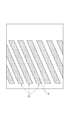
図6は積層造形物41の一部正面図である。
本構成の積層造形物41においては、螺旋状のブレード27の延設方向をビード形成方向Vbに一致させれば、溶着ビードの連続形成長さを長くできる。そのため、ビード形成方向Vbをブレード27の延設方向と同じにして、これを基準方向とする(S13)。これにより、ビードサイズは、基準方向(ビード形成方向Vb)に直交するVII-VII線断面で示すビード断面の形状を基準に制御する。
FIG. 6 is a partial front view of the
In the
例えば、特定方向に連続した少なくとも一つの突起部を有する積層造形物においては、この連続する特定方向に沿って溶着ビードを形成すれば、効率よく造形が行え、積層造形工程の煩雑化が軽減される。そこで、作製しようとする積層造形物の形状データから、まず、積層造形物の連続する特定方向を求める。この特定方向は、コンピュータによる演算によって、形状データを適宜なアルゴリズムで解析して決定してもよく、作業者が判断する等、人為的に決定してもよい。 For example, in a laminated model having at least one protrusion continuous in a specific direction, if a welded bead is formed along the continuous specific direction, efficient modeling can be performed and the complexity of the laminated modeling process is reduced. To. Therefore, from the shape data of the laminated model to be manufactured, first, the continuous specific direction of the laminated model is obtained. This specific direction may be determined by analyzing the shape data with an appropriate algorithm by calculation by a computer, or may be determined artificially by an operator or the like.
図7は図6に示すVII-VII線のA1部における断面図である。図中の横軸は、ブレード27の延設方向(基準方向)に直交する方向で、縦軸は軸体25の径方向となるビード積層方向である。
FIG. 7 is a cross-sectional view taken along the line A1 of line VII-VII shown in FIG. The horizontal axis in the figure is a direction orthogonal to the extending direction (reference direction) of the
ここで、ブレード27の積層造形領域47を、複数の仮想ビード層に層分解する(S14)。複数層の仮想ビード層のビード(仮想ビード51として示す)は、仮想ビード層の1層分のビード高さhに応じて、ブレード27の最終形状が内包されるように配置される。図示例では、点線で示す仮想ビード51を、軸体25(粗形材43C)の表面から順次積層(層H1,H2,・・・)して、7層目(層H7)においてブレード27の径方向最外縁部27aが覆われる場合を示す。つまり、ここでは合計7層の仮想ビード層を有する積層モデルとなる。
Here, the
この積層モデルは、図5に示す複数の積層造形領域47の全てに対して生成される。そして、各積層モデルにおいて、共通の断面でビードサイズを設計する。つまり、積層造形領域47の各仮想ビード層における仮想ビード51の配置位置(ビード積層高さh等)、ビードサイズ(ビード幅W等)、溶接条件、等の諸条件を設定する(S15)。なお、図7においては仮想ビード層を7つに分割しているが、ビードサイズ、積層造形物の大きさや形状、等に応じて分割層数は任意に設定できる。
This laminated model is generated for all of the plurality of
次に、上記のように設計された積層モデルに従ってビードを粗形材43C上に形成する手順を示すプログラムを生成する(S16)。このプログラムの生成は、図1に示すプログラム生成部33が行う。
Next, a program showing a procedure for forming a bead on the
ここでいうプログラムとは、入力された積層造形物の形状データから、所定の演算により設計されたビードの形成手順を、造形部11により実施させるための命令コードである。制御部37は、予め用意されたプログラムの中から所望のプログラムを特定し、この特定されたプログラムを実行することで、造形部11によって積層造形物41を製造させる。つまり、制御部37は、記憶部35から所望のプログラムを読み込み、このプログラムにしたがってビードを形成して、積層造形物41を造形する。
The program referred to here is an instruction code for causing the
図8はビードを形成する様子を模式的に示す工程説明図である。
造形コントローラ13(図1参照)は、造形部11を生成したプログラムにしたがって駆動して、積層造形物41の粗形材43Cにビード55A,55B,55C,・・・を順次に並設し、第1層目(層H1)のビード層を形成する。そして、第1層目(層H1)のビード層の上に第2層目(層H2)のビード55D,55E,・・・を順次に並設する。
FIG. 8 is a process explanatory diagram schematically showing how the beads are formed.
The modeling controller 13 (see FIG. 1) is driven according to the program that generated the
ここで、ビード55Dの外表面とビード55Bの外表面との境界をPc(ビード55Dの図中右側の境界)とし、境界Pcにおけるビード55Dの外表面の接線をL1、境界Pcにおけるビード55Bの外表面の接線をL2とする。また、接線L1とL2とのなす角をαとし、角αの二等分線をNとする。
Here, the boundary between the outer surface of the
ビード55Dに隣接する次のビード55Eは、境界Pcを目標位置として形成される。ビード55Eを形成する際、トーチ17のトーチ軸線の向きは、直線Lと概ね同じ方向に設定される。なお、ビード55Eを形成する目標位置は、境界Pcに限らず、ビード55Bとビード55Cとの間の境界Pcaにしてもよい。
The
造形コントローラ13は、各ビード55A~55E,・・・の形成時に、上記したプログラムに従ってトーチ17を図中奥側(紙面垂直方向)に向けて移動させ、シールドガスG雰囲気中で発生させたアークによりビード形成の目標位置付近を加熱する。そして、加熱により溶融した溶加材Fmが目標位置で凝固することで、新たなビードが形成される。これにより、図7に示す粗形状のビード層が形成される。ビード層が形成された積層造形領域47は、その後の適宜な加工によって所望のブレード27の形状に仕上げられる。
When the
ここで、本実施形態では、積層造形物の製造装置100の造形部11を駆動させてビードにより積層造形する積層造形物の積層造形手順を、層分割工程と、面分割工程と、連続線抽出工程と、延長方向推定工程と、ビード形成線決定工程とから設計する。
Here, in the present embodiment, the layer division step, the surface division step, and the continuous line extraction are performed by driving the
以下、具体的な積層造形手順の設計方法を、各工程毎に説明する。
図9は本実施形態に係る積層造形手順の設計方法を説明する図であって、(A)は積層造形物の斜視図、(B)は積層造形物の展開図である。図10は図9(B)におけるA-A断面図である。図11は層分割したブレードの1層目を面分割した状態を示す積層造形物の展開図である。図12は層分割したブレードの1層目を面分割した一つのブレードの展開図である。
Hereinafter, a specific design method for the laminated molding procedure will be described for each process.
9A and 9B are views for explaining the design method of the laminated modeling procedure according to the present embodiment, FIG. 9A is a perspective view of the laminated modeled object, and FIG. 9B is a developed view of the laminated modeled object. FIG. 10 is a cross-sectional view taken along the line AA in FIG. 9B. FIG. 11 is a developed view of a laminated model showing a state in which the first layer of the layer-divided blade is surface-divided. FIG. 12 is a development view of one blade in which the first layer of the layer-divided blade is surface-divided.
(層分割工程)
積層造形物の3次元形状データを用いて、積層造形物41の形状をビードの高さに応じて複数の層に分割する。図9(A)に示すように、複数のブレード27を有する積層造形物41を展開すると、図9(B)に示すように、各ブレード27が斜めに整列した状態となる。この展開図において、ブレード27を、軸体25の軸線に直交する方向に断面視すると、図10に示すように、ブレード27は、軸体25からなる基材から立設された形状となる。層分割工程では、このブレード27を、積層造形物41の3次元形状データを用い、ビードの高さに応じて複数の層に分割する。本例では、H1~H7の7層に分割している。
(Layer division process)
Using the three-dimensional shape data of the laminated model, the shape of the
(面分割工程)
分割された各層H1~H7の形状を複数のポリゴン面からなる領域Rに分割する。図11に示すものは、展開図におけるブレード27の1層目H1の平面形状を示している。この1層目H1において、その形状を複数のポリゴン面からなる領域Rに分割する。ここでは、四角形からなるポリゴン面でブレード27の1層目H1の平面形状をポリゴン面からなる複数の領域Rに分割している。
(Surface division process)
The shape of each of the divided layers H1 to H7 is divided into a region R composed of a plurality of polygon faces. What is shown in FIG. 11 shows the planar shape of the first layer H1 of the
(連結線抽出工程)
各層において、ブレード27の一端部27Aから他端部27Bに向けて、隣接する領域R同士を連結する連結線Lを求める。例えば、図12に示すように、ブレード27の一端部27Aにおける一つの領域Rを任意に選択する。ここでは、ブレード27の一端部27Aにおける左端の領域Rを選択する。次に、予め設定した設定方向Aに隣接する領域Rを選択し、これらの領域Rの中心位置を結ぶ連結線Lを求める。その後も設定方向Aに隣接する領域Rの中心位置を結ぶ連結線Lを順次求める。なお、領域Rの設定方向A側がブレード27の縁部となっているために設定方向Aに隣接する領域Rがない場合は、左側に隣接する領域Rを選択し、それぞれの中心位置を結ぶ連結線Lを求める。
(Connecting line extraction process)
In each layer, a connecting line L connecting adjacent regions R from one
なお、ブレード27の一端部27Aで選択する領域Rは、左端に限らず、中央または右端でもよく、いずれの場合も、連結線Lを求めていくことで、その後に同一ルートをたどることとなる(図12中点線参照)。
The region R selected by one
(延長方向推定工程)
抽出した連結線Lから、例えば、最小二乗法等によってビードを形成する方向であるブレード27の延長方向Bを求める。
(Extended direction estimation process)
From the extracted connecting line L, for example, the extension direction B of the
(ビード形成線決定工程)
分割されたブレード27の層を、推定した延長方向Bに沿って複数のビードに分割して、それぞれのビードを形成するための形成予定線Cを決定する。
(Bead formation line determination process)
The layer of the divided
そして、ブレード27の全ての層H1~H7において形成予定線Cを決定し、その決定した形成予定線Cに沿ってビード55を形成する。
Then, the planned formation line C is determined in all the layers H1 to H7 of the
このように、上記実施形態によれば、複数層に分割した積層造形物であるブレード27の各層H1~H7に領域Rを当てはめて分割し、これらの領域R同士を連結する連結線Lを求めて延長方向Bを割り出し、その延長方向Bに沿ってビードの形成予定線Cを決定する。具体的には、ブレード27の各層H1~H7の形状を複数のポリゴン面からなる領域Rに分割して連結線Lを求めて延長方向Bを割り出し、その延長方向に沿ってビードの形成予定線Cを決定する。これにより、ビードを形成する際の形成方向を適切かつ容易に決定することができ、最適な造形手順で効率的に積層造形が行える。
As described above, according to the above embodiment, the region R is applied to each layer H1 to H7 of the
なお、上記実施形態では、面分割工程において、各層H1~H7におけるブレード27の平面形状を四角形のポリゴン面からなる領域Rに分割したが、領域Rの形状は四角形に限らない。
In the above embodiment, in the surface division step, the planar shape of the
図13はブレードの1層目の形状を三角形のポリゴン面からなる領域に面分割したブレードの一部の展開図である。
図13に示すように、面分割工程において、各層H1~H7におけるブレード27の平面形状を三角形のポリゴン面からなる領域Rに分割してもよい。ここで、この三角形のポリゴン面からなる領域Rで分割した場合における連結線抽出工程について説明する。
FIG. 13 is a developed view of a part of the blade in which the shape of the first layer of the blade is divided into regions consisting of triangular polygon faces.
As shown in FIG. 13, in the surface division step, the planar shape of the
三角形のポリゴン面からなる領域Rで分割した場合、連結線Lの進行方向の選択の優先順位を、例えば、上、右、左とし、隣接する領域R同士を連結する連結線Lを求める。具体的には、ブレード27の一端部27Aにおける一つの領域Rを任意に選択し、予め設定した設定方向Aに隣接する領域Rを選択し、これらの領域Rの中心位置を結ぶ連結線Lを順次求める。このとき、設定方向Aに隣接する領域Rが存在しない場合は、進行方向の選択の優先順位に沿って隣接する領域Rを選択する。
When the area R is divided by the polygonal surface of the triangle, the priority of selection of the traveling direction of the connecting line L is set to, for example, upper, right, and left, and the connecting line L connecting the adjacent areas R is obtained. Specifically, one region R at one
その後は、抽出した連結線Lから、ビードを形成する方向であるブレード27の延長方向Bを求め(延長方向推定工程)、分割されたブレード27の層において、推定した延長方向Bに沿って複数のビードに分割して、それぞれのビードを形成するための形成予定線Cを決定する(ビード形成線決定工程)。
After that, the extension direction B of the
次に、延長方向の求め方の変形例について説明する。
図14は延長方向の求め方の変形例を説明する図であって、(A)から(D)は、それぞれブレードの面分割の仕方を示すブレードの模式図である。図15は延長方向の選定の仕方を示すグラフである。
Next, a modified example of how to obtain the extension direction will be described.
14A and 14B are views for explaining a modification of how to obtain the extension direction, and FIGS. 14A to 14D are schematic views of blades showing how to divide the surface of the blade, respectively. FIG. 15 is a graph showing how to select the extension direction.
変形例では、面分割工程において、分割された層に予め設定された設定形状の領域Rを当てはめ、この当てはめた領域Rに隣接する部分で設定形状を当てはめる際に、既に当てはめた領域Rに接する面の面積Sが最大となるように領域Rを設定していく。 In the modification, in the surface division step, the area R of the preset shape is applied to the divided layers, and when the set shape is applied in the portion adjacent to the applied area R, the area R is in contact with the already applied area R. The area R is set so that the area S of the surface becomes the maximum.
図14に示すものは、ブレード27に対して一端部27A側に、設定形状(平行四辺形)の領域R1を当てはめ、この領域R1に隣接する部分に同一形状の設定形状の領域R2を当てはめる場合を示している。図14(A)では、一端部27A側の領域R1の中心位置に対して隣接する部分の領域R2の中心位置が左側へ大きくずれており、設定方向Aに対して連結線Lの傾き角が-θ2となっている。図14(B)では、一端部27A側の領域R1の中心位置に対して隣接する部分の領域R2の中心位置が左側へずれており、設定方向Aに対して連結線Lの傾き角が-θ1となっている。図14(C)では、一端部27A側の領域R1の中心位置と隣接する部分の領域R2の中心位置とを連結する連結線Lが設定方向Aに一致している。図14(D)では、一端部27A側の領域R1の中心位置に対して隣接する部分の領域R2の中心位置が右側へずれており、設定方向Aに対して連結線Lの傾き角が+θ1となっている。
In the case shown in FIG. 14, a region R1 having a set shape (parallelogram) is fitted to one
このような場合において、図15に示すように、互いに隣接する領域R1,R2の接する面の面積Sは、設定方向Aに対する連結線Lの傾き角が-θ1のときに最大となっている。したがって、この場合、設定方向Aに対して領域R1,R2の連結線Lの傾き角が-θ1となるように面分割し、その連結線Lからブレード27の延長方向Bを求める。
In such a case, as shown in FIG. 15, the area S of the surfaces in contact with the regions R1 and R2 adjacent to each other is maximum when the inclination angle of the connecting line L with respect to the setting direction A is −θ1. Therefore, in this case, the surface is divided so that the inclination angle of the connecting line L of the regions R1 and R2 is −θ1 with respect to the setting direction A, and the extension direction B of the
このように、変形例によれば、積層造形物であるブレード27の各層H1~H7の形状に予め設定された設定形状の領域Rを当てはめ、この当てはめた領域Rに隣接する部分で設定形状の領域Rを当てはめる際に、既に当てはめた領域Rに接する面の面積が最大となるように領域Rを設定していく。そして、各領域Rの連結線Lを求めて延長方向Bを割り出し、その延長方向Bに沿ってビードの形成予定線Cを適切かつ容易に決定することができる。
As described above, according to the modified example, the area R of the preset shape is fitted to the shape of each layer H1 to H7 of the
このように、本発明は上記の実施形態に限定されるものではなく、実施形態の各構成を相互に組み合わせることや、明細書の記載、並びに周知の技術に基づいて、当業者が変更、応用することも本発明の予定するところであり、保護を求める範囲に含まれる。 As described above, the present invention is not limited to the above-described embodiment, and can be modified or applied by those skilled in the art based on the mutual combination of the configurations of the embodiments, the description of the specification, and the well-known technique. It is also a matter of the present invention to do so, and it is included in the scope of seeking protection.
以上の通り、本明細書には次の事項が開示されている。
(1) 一方向に延びる突起部を有する積層造形物を、溶加材を溶融及び凝固させて形成するビードにより積層造形する積層造形物の積層造形手順設計方法であって、
前記積層造形物の3次元形状データを用いて、前記積層造形物の形状を前記ビードの高さに応じて複数の層に分割する層分割工程と、
分割された前記層に予め設定された設定形状の領域を当てはめて分割する面分割工程と、
前記層の前記突起部の一端部から他端部に向けて、隣接する前記領域同士を連結する連結線を求める連結線抽出工程と、
前記連結線から前記突起部の延長方向を求める延長方向推定工程と、
分割された前記層を前記延長方向に沿って複数の前記ビードに分割して、前記ビードの形成予定線を決定するビード形成線決定工程と、
を含む、積層造形物の積層造形手順設計方法。
この積層造形物の積層造形手順設計方法によれば、複数層に分割した積層造形物の各層に領域を当てはめて分割し、これらの領域同士を連結する連結線を求めて延長方向を割り出し、その延長方向に沿ってビードの形成予定線を決定する。これにより、ビードを形成する際の形成方向を適切かつ容易に決定することができ、最適な造形手順で効率的に積層造形が行える。
As described above, the following matters are disclosed in this specification.
(1) A method for designing a laminated modeling procedure for a laminated model in which a laminated model having protrusions extending in one direction is laminated and formed by a bead formed by melting and solidifying a filler metal.
A layer dividing step of dividing the shape of the laminated model into a plurality of layers according to the height of the bead using the three-dimensional shape data of the laminated model.
A surface division step of applying a preset region of a set shape to the divided layers and dividing the layers.
A connecting line extraction step of obtaining a connecting line connecting adjacent regions from one end to the other end of the protrusion of the layer.
An extension direction estimation step for obtaining an extension direction of the protrusion from the connecting line,
A bead forming line determination step of dividing the divided layer into a plurality of the beads along the extension direction to determine a planned bead formation line.
Laminated modeling procedure design method for laminated objects, including.
According to the laminated modeling procedure design method of this laminated model, a region is applied to each layer of the laminated model divided into a plurality of layers and divided, and an extension direction is determined by finding a connecting line connecting these regions. Determine the planned bead formation line along the extension direction. As a result, the forming direction when forming the bead can be appropriately and easily determined, and the laminated molding can be efficiently performed by the optimum molding procedure.
(2) 前記面分割工程において、分割された前記層の形状を複数のポリゴン面からなる領域に分割する
(1)に記載の積層造形物の積層造形手順設計方法。
この積層造形物の積層造形手順設計方法によれば、積層造形物の各層の形状を複数のポリゴン面からなる領域に分割して連結線を求めて延長方向を割り出し、その延長方向に沿ってビードの形成予定線を適切かつ容易に決定することができる。
(2) The method for designing a laminated molding procedure for a laminated model according to (1), wherein the shape of the divided layer is divided into a region composed of a plurality of polygon faces in the surface dividing step.
According to this laminated modeling procedure design method, the shape of each layer of the laminated model is divided into regions consisting of a plurality of polygon faces, a connecting line is obtained, an extension direction is determined, and beads are formed along the extension direction. The planned formation line can be determined appropriately and easily.
(3) 前記面分割工程において、分割された前記層に、前記予め設定された設定形状の領域を当てはめ、更に当該領域に隣接する前記層の部分に前記設定形状の領域を当てはめることを繰り返し、
次に当てはめる領域を、前記層の部分と重なる面積が最大となるように選定する、
(1)に記載の積層造形物の積層造形手順設計方法。
この積層造形物の積層造形手順設計方法によれば、積層造形物の各層の形状に予め設定された設定形状の領域を当てはめ、この当てはめた領域に隣接する部分で設定形状の領域を当てはめる際に、既に当てはめた領域に接する面の面積が最大となるように領域を設定していく。そして、各領域の連結線を求めて延長方向を割り出し、その延長方向に沿ってビードの形成予定線を適切かつ容易に決定することができる。
(3) In the surface division step, the region of the preset shape is applied to the divided layer, and the region of the set shape is further applied to the portion of the layer adjacent to the region.
Next, the area to be applied is selected so that the area overlapping the portion of the layer is maximized.
The method for designing a laminated modeling procedure for a laminated model according to (1).
According to the laminated modeling procedure design method of this laminated model, when a region of a preset shape is fitted to the shape of each layer of the laminated model and a region of the set shape is fitted in a portion adjacent to the fitted area. , Set the area so that the area of the surface in contact with the already applied area is maximized. Then, the extension direction can be determined by finding the connecting line of each region, and the planned bead formation line can be appropriately and easily determined along the extension direction.
(4) (1)から(3)のいずれか一つに記載の積層造形物の積層造形手順設計方法により決定された前記造形手順により、前記積層造形物を造形する積層造形物の製造方法。
この積層造形物の製造方法によれば、ビード形成方向を適切かつ容易に行うことができ、高効率に積層造形が行える。
(4) A method for manufacturing a laminated model, in which the laminated model is modeled by the modeling procedure determined by the laminated modeling procedure design method according to any one of (1) to (3).
According to this method for manufacturing a laminated model, the bead forming direction can be appropriately and easily performed, and the laminated model can be performed with high efficiency.
(5) (4)に記載の積層造形物の製造方法の前記造形手順を決定する制御部と、
前記制御部により決定された前記造形手順に応じて駆動され、前記ビードを形成する造形部と、
を備える積層造形物の製造装置。
この積層造形物の製造装置によれば、積層造形物を高効率で造形できる。
(5) A control unit that determines the modeling procedure of the method for manufacturing a laminated model according to (4).
A modeling unit driven according to the modeling procedure determined by the control unit to form the bead, and a modeling unit.
Equipment for manufacturing laminated objects.
According to this laminated model manufacturing apparatus, the laminated model can be modeled with high efficiency.
(6) 一方向に延びる突起部を有する積層造形物の3次元形状データを用いて、溶加材を溶融及び凝固させて形成するビードで前記積層造形物を積層造形する積層造形手順を決定する手順を、コンピュータに実行させるプログラムであって、
前記コンピュータに、
前記積層造形物の3次元形状データを用いて、前記積層造形物の形状を前記ビードの高さに応じて複数の層に分割する手順と、
分割された前記層に複数の領域を当てはめて分割する手順と、
前記層の前記突起部の一端部から他端部に向けて、隣接する前記領域同士を連結する連結線を求める手順と、
前記連結線から前記突起部の延長方向を求める手順と、
分割された前記層を前記延長方向に沿って複数の前記ビードに分割して、前記ビードの形成予定線を決定する手順と、
を実行させるプログラム。
このプログラムによれば、ビードの形成予定線を、複数層に分割した積層造形物の各層に領域を当てはめて分割し、これらの領域同士を連結する連結線を求めて延長方向を割り出し、その延長方向に沿ってビードの形成予定線を決定する。これにより、ビード形成する際の形成方向を適切かつ容易に決定することができ、最適な造形手順で効率的に積層造形できる。
(6) Using the three-dimensional shape data of the laminated model having protrusions extending in one direction, the laminated modeling procedure for laminating the laminated model with a bead formed by melting and solidifying the filler metal is determined. A program that lets a computer execute a procedure
To the computer
A procedure for dividing the shape of the laminated model into a plurality of layers according to the height of the bead by using the three-dimensional shape data of the laminated model.
The procedure of applying a plurality of areas to the divided layers and dividing the layers,
A procedure for obtaining a connecting line connecting adjacent regions from one end to the other end of the protrusion of the layer, and a procedure for obtaining a connecting line.
The procedure for obtaining the extension direction of the protrusion from the connecting line and
A procedure for dividing the divided layer into a plurality of the beads along the extension direction to determine a planned formation line for the beads, and a procedure for determining the planned formation line of the beads.
A program to execute.
According to this program, the planned bead formation line is divided by applying a region to each layer of a laminated model divided into multiple layers, and the extension direction is determined by finding a connecting line connecting these regions and extending the region. Determine the planned bead formation line along the direction. As a result, the forming direction when forming the bead can be appropriately and easily determined, and the laminated molding can be efficiently performed by the optimum molding procedure.
13 造形コントローラ
17 トーチ
27 ブレード(突起部)
31 溶接方向決定部
33 プログラム生成部
35 記憶部
37 制御部
41 積層造形物
55A,55B,55C,55D,55E ビード
B 延長方向
C 形成予定線
Fm 溶加材
H1~H7 層
L 連結線
R 領域
13
31 Welding
Claims (6)
前記積層造形物の3次元形状データを用いて、前記積層造形物の形状を前記ビードの高さに応じて複数の層に分割する層分割工程と、
分割された前記層を前記ビードの高さ方向から平面視したときの前記層の平面形状に、予め設定された設定形状の領域を当てはめて、前記平面形状を複数の領域に面分割する面分割工程と、
前記層の前記突起部が延びる前記一方向の一端部から他端部に向けて、隣接する前記領域同士を連結する連結線を求める連結線抽出工程と、
前記連結線から前記突起部の延長方向を求める延長方向推定工程と、
分割された前記層を、前記延長方向に沿って複数の前記ビードを形成するビード領域に分割して、前記ビードの形成予定線を決定するビード形成線決定工程と、
を含む、積層造形物の積層造形手順設計方法。 It is a method of designing a laminated molding procedure for a laminated model in which a laminated model having protrusions extending in one direction orthogonal to the stacking direction is laminated by a bead formed by melting and solidifying a filler metal.
A layer dividing step of dividing the shape of the laminated model into a plurality of layers according to the height of the bead using the three-dimensional shape data of the laminated model.
A plane division in which a region of a preset setting shape is applied to the plane shape of the layer when the divided layer is viewed in a plan view from the height direction of the bead, and the plane shape is divided into a plurality of regions. Process and
A connecting line extraction step for obtaining a connecting line connecting adjacent regions from one end to the other in one direction in which the protrusion of the layer extends .
An extension direction estimation step for obtaining an extension direction of the protrusion from the connecting line,
A bead forming line determination step of dividing the divided layer into bead regions forming a plurality of the beads along the extension direction to determine a planned bead formation line.
Laminated modeling procedure design method for laminated objects, including.
請求項1に記載の積層造形物の積層造形手順設計方法。 In the surface division step, the divided shape of the layer is divided into a region composed of a plurality of polygon surfaces.
The method for designing a laminated modeling procedure for a laminated model according to claim 1.
次に当てはめる領域を、前記層と重なる面積が最大となるように選定する、
請求項1に記載の積層造形物の積層造形手順設計方法。 In the surface division step, the region of the preset shape is applied to the divided layer, and the region of the set shape is repeatedly applied to the portion of the layer adjacent to the region in one direction. ,
The area to be applied next is selected so that the area overlapping with the layer is maximized.
The method for designing a laminated modeling procedure for a laminated model according to claim 1.
前記制御部により決定された前記造形手順に応じて駆動され、前記ビードを形成する造形部と、
を備える積層造形物の製造装置。 A control unit that determines the modeling procedure according to the method for manufacturing a laminated model according to claim 4.
A modeling unit driven according to the modeling procedure determined by the control unit to form the bead, and a modeling unit.
Equipment for manufacturing laminated objects.
前記コンピュータに、
前記積層造形物の3次元形状データを用いて、前記積層造形物の形状を前記ビードの高さに応じて複数の層に分割する手順と、
分割された前記層を前記ビードの高さ方向から平面視したときの前記層の平面形状に、予め設定された設定形状の領域を当てはめて、前記平面形状を複数の領域に面分割する手順と、
前記層の前記突起部が延びる前記一方向の一端部から他端部に向けて、隣接する前記領域同士を連結する連結線を求める手順と、
前記連結線から前記突起部の延長方向を求める手順と、
分割された前記層を、前記延長方向に沿って複数の前記ビードを形成するビード領域に分割して、前記ビードの形成予定線を決定する手順と、
を実行させるプログラム。 Using the three-dimensional shape data of a laminated model having protrusions extending in one direction orthogonal to the stacking direction, a laminated modeling procedure for laminating the laminated model with a bead formed by melting and solidifying the filler metal is performed. A program that lets a computer perform the deciding procedure
To the computer
A procedure for dividing the shape of the laminated model into a plurality of layers according to the height of the bead by using the three-dimensional shape data of the laminated model.
A procedure for applying a preset region of a set shape to the planar shape of the layer when the divided layer is viewed in a plan view from the height direction of the bead, and dividing the planar shape into a plurality of regions. ,
A procedure for obtaining a connecting line connecting adjacent regions from one end to the other in one direction in which the protrusion of the layer extends .
The procedure for obtaining the extension direction of the protrusion from the connecting line and
A procedure of dividing the divided layer into bead regions forming a plurality of the beads along the extension direction to determine a planned formation line of the beads.
A program to execute.
Priority Applications (5)
| Application Number | Priority Date | Filing Date | Title |
|---|---|---|---|
| JP2018095769A JP7020995B2 (en) | 2018-05-17 | 2018-05-17 | Modeling procedure design method for laminated model, modeling method and manufacturing equipment for laminated model, and program |
| CN201980032842.6A CN112166002B (en) | 2018-05-17 | 2019-04-19 | Method and apparatus for manufacturing layered structure, and storage medium |
| US17/050,660 US11415962B2 (en) | 2018-05-17 | 2019-04-19 | Additively-manufactured object by forming beads along a formation projected line of beads |
| EP19803104.9A EP3795277B1 (en) | 2018-05-17 | 2019-04-19 | Production method and production apparatus for additive manufacturing product, and program |
| PCT/JP2019/016909 WO2019220867A1 (en) | 2018-05-17 | 2019-04-19 | Production method and production apparatus for additive manufacturing product, and program |
Applications Claiming Priority (1)
| Application Number | Priority Date | Filing Date | Title |
|---|---|---|---|
| JP2018095769A JP7020995B2 (en) | 2018-05-17 | 2018-05-17 | Modeling procedure design method for laminated model, modeling method and manufacturing equipment for laminated model, and program |
Publications (2)
| Publication Number | Publication Date |
|---|---|
| JP2019199049A JP2019199049A (en) | 2019-11-21 |
| JP7020995B2 true JP7020995B2 (en) | 2022-02-16 |
Family
ID=68540093
Family Applications (1)
| Application Number | Title | Priority Date | Filing Date |
|---|---|---|---|
| JP2018095769A Active JP7020995B2 (en) | 2018-05-17 | 2018-05-17 | Modeling procedure design method for laminated model, modeling method and manufacturing equipment for laminated model, and program |
Country Status (5)
| Country | Link |
|---|---|
| US (1) | US11415962B2 (en) |
| EP (1) | EP3795277B1 (en) |
| JP (1) | JP7020995B2 (en) |
| CN (1) | CN112166002B (en) |
| WO (1) | WO2019220867A1 (en) |
Families Citing this family (5)
| Publication number | Priority date | Publication date | Assignee | Title |
|---|---|---|---|---|
| US11331848B2 (en) * | 2019-11-26 | 2022-05-17 | Mark Saberton | 3D printing bead configuration |
| CN111014670B (en) * | 2019-12-13 | 2021-03-19 | 株洲国创轨道科技有限公司 | Machining area division and machining method of multi-machining-head additive manufacturing equipment |
| CN114103126B (en) * | 2021-11-26 | 2022-11-18 | 南京衍构科技有限公司 | 3D printing scanning filling path planning method for revolving body with unequal wall thickness |
| CN115846690A (en) * | 2022-12-01 | 2023-03-28 | 沈阳航空航天大学 | Characteristic partition rapid intelligent identification and process planning method for additive manufacturing and repair |
| CN115945698B (en) * | 2023-03-13 | 2023-05-23 | 西安石油大学 | Metal cladding layer forming quality optimization method based on CMT additive remanufacturing |
Citations (8)
| Publication number | Priority date | Publication date | Assignee | Title |
|---|---|---|---|---|
| WO2003016031A1 (en) | 2001-08-16 | 2003-02-27 | Riken | Rapid prototyping method and device using v-cad data |
| JP2007275945A (en) | 2006-04-07 | 2007-10-25 | Asahi Glass Co Ltd | Molding method for manufacturing molded article of three dimensional free shape, and apparatus therefor |
| JP2009006509A (en) | 2007-06-26 | 2009-01-15 | Panasonic Electric Works Co Ltd | Method and apparatus for manufacture of three-dimensional article |
| JP2009113294A (en) | 2007-11-05 | 2009-05-28 | Sony Corp | Optical modeling apparatus and optical modeling method |
| JP2011506763A (en) | 2007-12-14 | 2011-03-03 | シーバー フォーミング ソリューションズ ゲーエムベーハー | Method and apparatus for producing an annular rotationally symmetric workpiece from metal powder and / or ceramic powder using metal powder and / or ceramic powder and laser beam |
| JP2016198974A (en) | 2015-04-13 | 2016-12-01 | ローランドディー.ジー.株式会社 | Slice model generation apparatus and three-dimensional molding system |
| JP2018012336A (en) | 2017-08-25 | 2018-01-25 | 技術研究組合次世代3D積層造形技術総合開発機構 | Three-dimensional laminate molding device, control method of three-dimensional laminate molding device and control program of three-dimensional laminate molding device |
| WO2018026962A1 (en) | 2016-08-03 | 2018-02-08 | 3Deo,Inc. | Devices and methods for three-dimensional printing |
Family Cites Families (9)
| Publication number | Priority date | Publication date | Assignee | Title |
|---|---|---|---|---|
| JP5024001B2 (en) | 2007-12-03 | 2012-09-12 | ソニー株式会社 | Stereolithography apparatus and stereolithography method |
| WO2016149774A1 (en) | 2015-03-26 | 2016-09-29 | Atlas Copco Airpower, Naamloze Vennootschap | Method for manufacturing a centrifugal metal impeller and a centrifugal impeller obtained with such a method |
| US20160327113A1 (en) * | 2015-05-07 | 2016-11-10 | Kevin Shelley | Apparatus, system, and method for absorbing mechanical energy |
| WO2018079304A1 (en) * | 2016-10-25 | 2018-05-03 | 株式会社ダイヘン | Copper alloy powder, laminate molding production method, and laminate molding |
| JP6575500B2 (en) | 2016-12-15 | 2019-09-18 | 日亜化学工業株式会社 | Method for producing nitride phosphor |
| CN107599382A (en) * | 2017-08-15 | 2018-01-19 | 华中科技大学 | A kind of laser power adjusting method based on the aspect of model |
| JP6738789B2 (en) * | 2017-11-29 | 2020-08-12 | 株式会社神戸製鋼所 | Laminated object design method, manufacturing method, manufacturing apparatus, and program |
| US10746479B2 (en) * | 2018-02-09 | 2020-08-18 | General Electric Company | Additively manufactured structures for thermal and/or mechanical systems, and methods for manufacturing the structures |
| EP3778197A4 (en) * | 2018-04-13 | 2022-06-22 | Tokyo Ohka Kogyo Co., Ltd. | Composition for cladding, and method for producing metal/resin bonded member |
-
2018
- 2018-05-17 JP JP2018095769A patent/JP7020995B2/en active Active
-
2019
- 2019-04-19 EP EP19803104.9A patent/EP3795277B1/en active Active
- 2019-04-19 CN CN201980032842.6A patent/CN112166002B/en active Active
- 2019-04-19 US US17/050,660 patent/US11415962B2/en active Active
- 2019-04-19 WO PCT/JP2019/016909 patent/WO2019220867A1/en active Application Filing
Patent Citations (8)
| Publication number | Priority date | Publication date | Assignee | Title |
|---|---|---|---|---|
| WO2003016031A1 (en) | 2001-08-16 | 2003-02-27 | Riken | Rapid prototyping method and device using v-cad data |
| JP2007275945A (en) | 2006-04-07 | 2007-10-25 | Asahi Glass Co Ltd | Molding method for manufacturing molded article of three dimensional free shape, and apparatus therefor |
| JP2009006509A (en) | 2007-06-26 | 2009-01-15 | Panasonic Electric Works Co Ltd | Method and apparatus for manufacture of three-dimensional article |
| JP2009113294A (en) | 2007-11-05 | 2009-05-28 | Sony Corp | Optical modeling apparatus and optical modeling method |
| JP2011506763A (en) | 2007-12-14 | 2011-03-03 | シーバー フォーミング ソリューションズ ゲーエムベーハー | Method and apparatus for producing an annular rotationally symmetric workpiece from metal powder and / or ceramic powder using metal powder and / or ceramic powder and laser beam |
| JP2016198974A (en) | 2015-04-13 | 2016-12-01 | ローランドディー.ジー.株式会社 | Slice model generation apparatus and three-dimensional molding system |
| WO2018026962A1 (en) | 2016-08-03 | 2018-02-08 | 3Deo,Inc. | Devices and methods for three-dimensional printing |
| JP2018012336A (en) | 2017-08-25 | 2018-01-25 | 技術研究組合次世代3D積層造形技術総合開発機構 | Three-dimensional laminate molding device, control method of three-dimensional laminate molding device and control program of three-dimensional laminate molding device |
Also Published As
| Publication number | Publication date |
|---|---|
| CN112166002B (en) | 2022-11-08 |
| WO2019220867A1 (en) | 2019-11-21 |
| EP3795277A1 (en) | 2021-03-24 |
| EP3795277B1 (en) | 2024-01-31 |
| EP3795277A4 (en) | 2022-01-26 |
| US20210080931A1 (en) | 2021-03-18 |
| US11415962B2 (en) | 2022-08-16 |
| JP2019199049A (en) | 2019-11-21 |
| CN112166002A (en) | 2021-01-01 |
Similar Documents
| Publication | Publication Date | Title |
|---|---|---|
| JP7020995B2 (en) | Modeling procedure design method for laminated model, modeling method and manufacturing equipment for laminated model, and program | |
| JP6738789B2 (en) | Laminated object design method, manufacturing method, manufacturing apparatus, and program | |
| JP7120774B2 (en) | Laminate-molded article modeling procedure design method, laminate-molded article modeling method, manufacturing apparatus, and program | |
| JP7048435B2 (en) | Laminating planning method of laminated model, manufacturing method and manufacturing equipment of laminated model | |
| CN109834408A (en) | Method and system for tool increasing material manufacturing | |
| CN109834409A (en) | Method and system for increasing material manufacturing | |
| CN111867769B (en) | Method for producing shaped article, and shaped article | |
| JP7048374B2 (en) | Manufacturing method of modeled object and modeled object | |
| JP6997040B2 (en) | Manufacturing method of laminated model and inspection method of laminated model | |
| JP2020001075A (en) | Lamination molding plan design method of laminate molded article, production method, production device and program | |
| JP7428621B2 (en) | How to set printing conditions, additive manufacturing method, additive manufacturing system, and program | |
| JP6892542B1 (en) | Manufacturing method of modeled object and modeled object | |
| JP2020192605A (en) | Laminate molding method | |
| JP2023040767A (en) | Method for manufacturing molded article and molded article | |
| JP2024025180A (en) | Control information generation device, control information generation method, program, and laminate molding method | |
| CN116457080A (en) | Method for producing molded article and molded article |
Legal Events
| Date | Code | Title | Description |
|---|---|---|---|
| A621 | Written request for application examination |
Free format text: JAPANESE INTERMEDIATE CODE: A621 Effective date: 20201130 |
|
| A131 | Notification of reasons for refusal |
Free format text: JAPANESE INTERMEDIATE CODE: A131 Effective date: 20211019 |
|
| A521 | Request for written amendment filed |
Free format text: JAPANESE INTERMEDIATE CODE: A523 Effective date: 20211101 |
|
| TRDD | Decision of grant or rejection written | ||
| A01 | Written decision to grant a patent or to grant a registration (utility model) |
Free format text: JAPANESE INTERMEDIATE CODE: A01 Effective date: 20220125 |
|
| A61 | First payment of annual fees (during grant procedure) |
Free format text: JAPANESE INTERMEDIATE CODE: A61 Effective date: 20220203 |
|
| R150 | Certificate of patent or registration of utility model |
Ref document number: 7020995 Country of ref document: JP Free format text: JAPANESE INTERMEDIATE CODE: R150 |