JP7013763B2 - Wiping device and droplet ejection device - Google Patents
Wiping device and droplet ejection device Download PDFInfo
- Publication number
- JP7013763B2 JP7013763B2 JP2017181221A JP2017181221A JP7013763B2 JP 7013763 B2 JP7013763 B2 JP 7013763B2 JP 2017181221 A JP2017181221 A JP 2017181221A JP 2017181221 A JP2017181221 A JP 2017181221A JP 7013763 B2 JP7013763 B2 JP 7013763B2
- Authority
- JP
- Japan
- Prior art keywords
- wiping
- pair
- wiping member
- rolls
- roll
- Prior art date
- Legal status (The legal status is an assumption and is not a legal conclusion. Google has not performed a legal analysis and makes no representation as to the accuracy of the status listed.)
- Active
Links
Images


Landscapes
- Ink Jet (AREA)
Description
本発明は、払拭装置及び液滴吐出装置に関する。 The present invention relates to a wiping device and a droplet ejection device.
液滴吐出ヘッドのノズル面を払拭するウェブと、そのウェブを走行させる駆動手段と、そのウェブをノズル面に押し当てる押し当て部材と、その押し当て部材を支持する支持部材と、を備えたヘッドクリーニング装置は、従来に提案されている(例えば、特許文献1参照)。 A head provided with a web for wiping the nozzle surface of the droplet ejection head, a driving means for traveling the web, a pressing member for pressing the web against the nozzle surface, and a support member for supporting the pressing member. Cleaning devices have been conventionally proposed (see, for example, Patent Document 1).
本発明は、液滴吐出ヘッドのノズル面を払拭する払拭部材が巻き掛けられるロールが取り外し不能に構成されている場合又は個別にしか取り外せないように構成されている場合に比べて、払拭部材の交換時の作業性を向上できる払拭装置及び液滴吐出装置を得ることを目的とする。 In the present invention, as compared with the case where the roll around which the wiping member for wiping the nozzle surface of the droplet ejection head is wound is configured to be non-removable or configured to be removable only individually, the wiping member It is an object of the present invention to obtain a wiping device and a droplet ejection device that can improve workability at the time of replacement.
上記の目的を達成するために、本発明に係る請求項1に記載の払拭装置は、液滴吐出ヘッドのノズル面を払拭する払拭部材と、前記払拭部材に下方から接触し、前記ノズル面に前記払拭部材を接触させる第1ロールと、前記第1ロールにおける前記払拭部材の繰出方向上流側及び下流側に配置され、前記払拭部材に下方から接触する一対の第2ロールと、前記第1ロールと前記一対の第2ロールとの間に配置され、前記払拭部材に上方から接触する一対の第3ロールと、前記一対の第3ロールを前記払拭部材から同時に退避させる退避手段と、前記払拭部材を繰り出す繰出ロールと前記払拭部材を巻き取る巻取ロールとが収容された筐体と、を備え、前記退避手段は、前記一対の第3ロールを支持し、前記筐体に対して脱着される蓋部材で構成され、前記蓋部材は、前記筐体における前記繰出ロールの軸方向一端部側に設けられている。 In order to achieve the above object, the wiping device according to claim 1 according to the present invention has a wiping member that wipes the nozzle surface of the droplet ejection head and the wiping member that comes into contact with the wiping member from below and touches the nozzle surface. A first roll that brings the wiping member into contact, a pair of second rolls that are arranged on the upstream side and the downstream side of the wiping member in the feeding direction in the first roll and that come into contact with the wiping member from below, and the first roll. A pair of third rolls arranged between the and the pair of second rolls and in contact with the wiping member from above, a retracting means for simultaneously retracting the pair of third rolls from the wiping member, and the wiping member . A housing including a feeding roll for feeding and a winding roll for winding the wiping member is provided , and the retracting means supports the pair of third rolls and is attached to and detached from the housing. It is composed of a lid member, and the lid member is provided on one end side in the axial direction of the feeding roll in the housing .
また、本発明に係る請求項2に記載の払拭装置は、液滴吐出ヘッドのノズル面を払拭する払拭部材と、前記払拭部材に下方から接触し、前記ノズル面に前記払拭部材を接触させる第1ロールと、前記第1ロールにおける前記払拭部材の繰出方向上流側及び下流側に配置され、前記払拭部材に下方から接触する一対の第2ロールと、前記第1ロールと前記一対の第2ロールとの間に配置され、前記払拭部材に上方から接触する一対の第3ロールと、前記一対の第3ロールを前記払拭部材から同時に退避させる退避手段と、前記払拭部材を繰り出す繰出ロールと前記払拭部材を巻き取る巻取ロールとが収容された筐体と、を備え、前記退避手段は、前記一対の第3ロールを支持し、前記筐体に対して脱着される蓋部材で構成され、前記蓋部材は、前記筐体の上側に設けられている。 Further, the wiping device according to claim 2 according to the present invention has a wiping member that wipes the nozzle surface of the droplet ejection head, and the wiping member that comes into contact with the wiping member from below to bring the wiping member into contact with the nozzle surface. One roll, a pair of second rolls arranged on the upstream side and the downstream side of the wiping member in the feeding direction of the first roll and in contact with the wiping member from below, and the first roll and the pair of second rolls. A pair of third rolls arranged between the two, and a pair of third rolls that come into contact with the wiping member from above, a retracting means for simultaneously retracting the pair of third rolls from the wiping member, a feeding roll for feeding the wiping member, and the wiping. The retracting means comprises a housing in which a winding roll for winding the member is housed , and the retracting means is composed of a lid member that supports the pair of third rolls and is attached to and detached from the housing. The lid member is provided on the upper side of the housing .
また、請求項3に記載の払拭装置は、請求項1に記載の払拭装置であって、前記蓋部材は、前記一対の第3ロールの位置を変更可能なように、該第3ロールを取付可能な複数の取付部を有している。 Further, the wiping device according to claim 3 is the wiping device according to claim 1 , and the lid member is attached with the third roll so that the positions of the pair of third rolls can be changed. It has a plurality of possible mounting parts.
また、請求項4に記載の払拭装置は、請求項1~請求項3の何れか1項に記載の払拭装置であって、前記筐体は、前記蓋部材が装着されたことを検知する検知手段を有している。 The wiping device according to claim 4 is the wiping device according to any one of claims 1 to 3, wherein the housing detects that the lid member is attached. Have the means.
また、本発明に係る請求項5に記載の払拭装置は、液滴吐出ヘッドのノズル面を払拭する払拭部材と、前記払拭部材に下方から接触し、前記ノズル面に前記払拭部材を接触させる第1ロールと、前記第1ロールにおける前記払拭部材の繰出方向上流側及び下流側に配置され、前記払拭部材に下方から接触する一対の第2ロールと、前記第1ロールと前記一対の第2ロールとの間に配置され、前記払拭部材に上方から接触する一対の第3ロールと、前記一対の第3ロールを前記払拭部材から同時に退避させる退避手段と、前記払拭部材を繰り出す繰出ロールと前記払拭部材を巻き取る巻取ロールとが収容された筐体と、を備え、前記退避手段は、前記一対の第3ロールを支持し、前記筐体に対して脱着される脱着部材で構成され、前記筐体は、前記脱着部材が装着されたことを検知する検知手段を有している。 The wiping device according to claim 5 according to the present invention has a wiping member that wipes the nozzle surface of the droplet ejection head, and the wiping member that comes into contact with the wiping member from below to bring the wiping member into contact with the nozzle surface. One roll, a pair of second rolls arranged on the upstream side and the downstream side of the wiping member in the feeding direction of the first roll and in contact with the wiping member from below, and the first roll and the pair of second rolls. A pair of third rolls arranged between the two, and a pair of third rolls that come into contact with the wiping member from above, a retracting means for simultaneously retracting the pair of third rolls from the wiping member, a feeding roll for feeding the wiping member, and the wiping. The retracting means comprises a housing in which a take-up roll for winding the member is housed, and the retracting means is composed of a detachable member that supports the pair of third rolls and is attached to and detached from the housing. The housing has a detecting means for detecting that the detachable member is attached .
また、本発明に係る請求項6に記載の払拭装置は、液滴吐出ヘッドのノズル面を払拭する払拭部材と、前記払拭部材に下方から接触し、前記ノズル面に前記払拭部材を接触させる第1ロールと、前記第1ロールにおける前記払拭部材の繰出方向上流側及び下流側に配置され、前記払拭部材に下方から接触する一対の第2ロールと、前記第1ロールと前記一対の第2ロールとの間に配置され、前記払拭部材に上方から接触する一対の第3ロールと、前記一対の第3ロールを前記払拭部材から同時に退避させる退避手段と、前記払拭部材を繰り出す繰出ロールと前記払拭部材を巻き取る巻取ロールとが収容された筐体と、を備え、前記退避手段は、前記一対の第3ロールを支持し、前記筐体に回転可能に支持された回転部材で構成されている。 The wiping device according to claim 6 according to the present invention has a wiping member that wipes the nozzle surface of the droplet ejection head, and the wiping member that comes into contact with the wiping member from below to bring the wiping member into contact with the nozzle surface. One roll, a pair of second rolls arranged on the upstream side and the downstream side of the wiping member in the feeding direction of the first roll and in contact with the wiping member from below, and the first roll and the pair of second rolls. A pair of third rolls arranged between the two, and a pair of third rolls that come into contact with the wiping member from above, a retracting means for simultaneously retracting the pair of third rolls from the wiping member, a feeding roll for feeding the wiping member, and the wiping. A housing including a winding roll for winding the member is provided, and the retracting means is composed of a rotating member that supports the pair of third rolls and is rotatably supported by the housing. There is.
また、請求項7に記載の払拭装置は、請求項6に記載の払拭装置であって、前記筐体又は前記回転部材は、前記一対の第3ロールを上方位置にて保持する保持手段を有している。 The wiping device according to claim 7 is the wiping device according to claim 6, and the housing or the rotating member has a holding means for holding the pair of third rolls at an upper position. is doing.
また、請求項8に記載の払拭装置は、請求項6又は請求項7に記載の払拭装置であって、前記筐体は、前記回転部材の回転により前記一対の第3ロールが前記払拭部材に接触したことを検知する検知手段を有している。 The wiping device according to claim 8 is the wiping device according to claim 6 or 7, and in the housing, the pair of third rolls are attached to the wiping member by the rotation of the rotating member. It has a detection means for detecting the contact.
また、本発明に係る請求項9に記載の払拭装置は、液滴吐出ヘッドのノズル面を払拭する払拭部材と、前記払拭部材に下方から接触し、前記ノズル面に前記払拭部材を接触させる第1ロールと、前記第1ロールにおける前記払拭部材の繰出方向上流側及び下流側に配置され、前記払拭部材に下方から接触する一対の第2ロールと、前記第1ロールと前記一対の第2ロールとの間に配置され、前記払拭部材に上方から接触する一対の第3ロールと、前記一対の第3ロールを前記払拭部材から同時に退避させる退避手段と、前記払拭部材を繰り出す繰出ロールと前記払拭部材を巻き取る巻取ロールとが収容された筐体と、を備え、前記退避手段は、前記一対の第3ロールの軸方向一端部側を連結する連結部材と、前記筐体に設けられ、前記連結部材が上下方向に移動可能となるように、前記一対の第3ロールの軸方向他端部側を支持する支持部材と、を有している。 The wiping device according to claim 9 , wherein the wiping member that wipes the nozzle surface of the droplet ejection head is in contact with the wiping member from below, and the wiping member is brought into contact with the nozzle surface. One roll, a pair of second rolls arranged on the upstream side and the downstream side of the wiping member in the feeding direction of the first roll and in contact with the wiping member from below, and the first roll and the pair of second rolls. A pair of third rolls arranged between the two, and a pair of third rolls that come into contact with the wiping member from above, a retracting means for simultaneously retracting the pair of third rolls from the wiping member, a feeding roll for feeding the wiping member, and the wiping. A housing including a winding roll for winding the member is provided, and the retracting means is provided in the housing with a connecting member for connecting one end side in the axial direction of the pair of third rolls. It has a support member that supports the other end side in the axial direction of the pair of third rolls so that the connecting member can move in the vertical direction.
また、請求項10に記載の払拭装置は、請求項9に記載の払拭装置であって、前記筐体は、前記連結部材の移動により前記一対の第3ロールが前記払拭部材に接触したことを検知する検知手段を有している。
Further, the wiping device according to
また、本発明に係る請求項11に記載の液滴吐出装置は、請求項1~請求項10の何れか1項に記載の払拭装置と、前記払拭装置に対して相対的に移動する液滴吐出ヘッドと、を備えている。 Further, the droplet ejection device according to claim 11 according to the present invention includes the wiping device according to any one of claims 1 to 10 and the droplets that move relative to the wiping device. It is equipped with a discharge head.
請求項1及び請求項2及び請求項5及び請求項6及び請求項9に係る発明によれば、液滴吐出ヘッドのノズル面を払拭する払拭部材が巻き掛けられるロールが取り外し不能に構成されている場合又は個別にしか取り外せないように構成されている場合に比べて、払拭部材の交換時の作業性を向上させることができる。 According to the inventions of claim 1 and 2, claim 5, claim 6 and claim 9 , the roll around which the wiping member for wiping the nozzle surface of the droplet ejection head is wound is configured to be non-removable. It is possible to improve the workability at the time of replacement of the wiping member as compared with the case where the wiping member is provided or the case where the wiping member is configured to be removable only individually.
請求項1及び請求項2に係る発明によれば、一対の第3ロールが、筐体から取り外せない部材に設けられている場合に比べて、第3ロールの清掃又は交換時の作業性を向上させることができる。 According to the first and second aspects of the invention, workability at the time of cleaning or replacement of the third roll is improved as compared with the case where the pair of third rolls are provided on the member that cannot be removed from the housing. Can be made to.
請求項1及び請求項2に係る発明によれば、一対の第3ロールを、それ専用の部材に設ける場合に比べて、部品点数を低減させることができる。 According to the first and second aspects of the invention, the number of parts can be reduced as compared with the case where the pair of third rolls is provided on the dedicated member .
請求項3に係る発明によれば、払拭部材の経路の変更に対応することができる。 According to the third aspect of the present invention, it is possible to cope with the change of the route of the wiping member .
請求項4及び請求項5及び請求項8及び請求項10に係る発明によれば、一対の第3ロールの付け忘れを防止することができる。 According to the inventions of claim 4 , claim 5, claim 8 and claim 10 , it is possible to prevent forgetting to attach the pair of third rolls.
請求項6に係る発明によれば、一対の第3ロールが、筐体から外れてしまう部材に設けられている場合に比べて、第3ロールの紛失を抑制することができる。 According to the sixth aspect of the present invention, it is possible to suppress the loss of the third roll as compared with the case where the pair of third rolls are provided on the member that comes off the housing.
請求項7に係る発明によれば、一対の第3ロールが上方位置にて保持されない場合に比べて、第3ロールの清掃又は交換時の作業性を向上させることができる。 According to the invention of claim 7, the workability at the time of cleaning or replacement of the third roll can be improved as compared with the case where the pair of third rolls is not held in the upper position.
請求項9に係る発明によれば、一対の第3ロールの軸方向他端部側が筐体に支持され、一対の第3ロールの軸方向一端部側を連結する連結部材が上下方向に移動不能とされている場合に比べて、第3ロールの清掃又は交換時の作業性を向上させることができる。 According to the invention of claim 9, the other end side in the axial direction of the pair of third rolls is supported by the housing, and the connecting member connecting the one end side in the axial direction of the pair of third rolls cannot move in the vertical direction. It is possible to improve the workability at the time of cleaning or replacing the third roll as compared with the case where.
請求項11に係る発明によれば、請求項1~請求項10の何れか1項に記載の払拭装置を備えていない場合に比べて、画像品質の低下を抑制することができる。 According to the invention of claim 11, deterioration of image quality can be suppressed as compared with the case where the wiping device according to any one of claims 1 to 10 is not provided.
以下、本発明の実施の形態について、図面を基に詳細に説明する。なお、説明の便宜上、各図に適宜示される矢印UPを液滴吐出装置の一例としてのインクジェット記録装置10及び払拭装置40の上方向とし、矢印LHを払拭装置40の左方向とし、矢印FRを払拭装置40の前方向とするが、各方向に特に限定されるものではない。更に、以下において、記録媒体の一例としての記録用紙Pの搬送方向を単に「搬送方向」と言い、その搬送方向上流側及び搬送方向下流側を、それぞれ単に「上流側」、「下流側」と言う場合がある。
Hereinafter, embodiments of the present invention will be described in detail with reference to the drawings. For convenience of explanation, the arrow UP shown in each figure is the upward direction of the
<インクジェット記録装置>
図1に示されるように、インクジェット記録装置10は、記録用紙Pが収容される給紙部12と、給紙部12から繰り出された記録用紙Pに画像を記録する画像記録部14と、画像記録部14へ記録用紙Pを搬送する搬送手段16と、画像記録部14によって画像が記録された記録用紙Pを収容する排紙部18と、を有している。
<Inkjet recording device>
As shown in FIG. 1, the
画像記録部14は、液滴吐出ヘッドの一例としてのインクジェット記録ヘッド20を有している。インクジェット記録ヘッド20は、複数のノズル(図示省略)が形成されたノズル面21を有しており、そのノズル面21は、インクジェット記録装置10での画像記録が想定される記録用紙Pの最大幅と同程度か、又はそれ以上の記録可能領域を有している。
The
また、インクジェット記録ヘッド20は、記録用紙Pの搬送方向に対して、その上流側からイエロー(Y)、マゼンタ(M)、シアン(C)、ブラック(K)の順に並設されており、サーマル方式や圧電方式等の公知の手段によって、インク滴(液滴)が吐出されるように構成されている。 Further, the inkjet recording heads 20 are arranged side by side in the order of yellow (Y), magenta (M), cyan (C), and black (K) from the upstream side with respect to the transport direction of the recording paper P, and are thermal. Ink droplets (droplets) are configured to be ejected by a known means such as a method or a piezoelectric method.
なお、インクとしては、水性インク、油性インク、溶剤系インク等の各種インクが使用可能である。また、インクジェット記録装置10には、各インクジェット記録ヘッド20Y、20M、20C、20Kにインクを供給するインクタンク22Y、22M、22C、22Kが配設されている。
As the ink, various inks such as water-based ink, oil-based ink, and solvent-based ink can be used. Further, the
また、インクジェット記録ヘッド20は、ラック・ピニオンやスライドガイド等の公知の移動機構により、その長手方向(記録用紙Pの幅方向)に移動可能に構成されている。より具体的には、インクジェット記録ヘッド20は、画像記録部14(搬送手段16上)から退避可能になっており、画像記録部14の隣に配置されたメンテナンス部(図示省略)へ移動可能に構成されている。
Further, the
一方、給紙部12に収容されている複数枚の記録用紙Pは、ピックアップローラー24によって1枚ずつ取り出されるように構成されており、搬送ローラー対25によって画像記録部14へ搬送されるように構成されている。
On the other hand, the plurality of recording sheets P accommodated in the
搬送手段16は、記録用紙Pの印刷面をインクジェット記録ヘッド20のノズル面21に対して予め決められた間隔(例えば1mm程度)で対面させるための搬送ベルト30を有している。搬送ベルト30は、下流側に配置された駆動ローラー26と、上流側に配置された従動ローラー28とに張架されて、図示の矢印A方向に循環駆動(回転)するように構成されている。
The transport means 16 has a
また、従動ローラー28の上部には、搬送ベルト30の表面側から、その搬送ベルト30に従動する帯電ローラー32が配設されている。この帯電ローラー32によって搬送ベルト30が帯電される(電荷が与えられる)ことにより、記録用紙Pが搬送ベルト30に静電吸着されて搬送される構成になっている。
Further, on the upper portion of the driven
なお、搬送ベルト30は、記録用紙Pを静電吸着して保持する構成とされるものに限定されるものではなく、記録用紙Pとの摩擦や記録用紙Pを吸引又は粘着するなどの非静電的吸着手段によって保持する構成とされていてもよい。また、搬送ベルト30の下流側には、複数の搬送ローラー対35と複数の搬送ローラー対38とが配設されている。
The
また、搬送ベルト30の下方には、反転部34が設けられている。したがって、両面印刷するときには、搬送ローラー対35によって搬送された記録用紙Pが、反転部34の複数の搬送ローラー対36によって更に搬送され、再度インクジェット記録ヘッド20へ送られるようになっている。そして、画像が記録された記録用紙Pは、搬送ベルト30から剥離され、搬送ローラー対35及び搬送ローラー対38によって搬送されて、排紙部18へ排出される構成になっている。
Further, a reversing
なお、このインクジェット記録装置10には、画像信号に応じてインク滴の吐出タイミングと使用するノズルを決定し、そのノズルに駆動信号を印加するインクジェット記録ヘッド20のヘッド制御部(図示省略)と、インクジェット記録装置10全体の動作を制御する制御部の一例としてのシステム制御部23と、が備えられている。
The
<払拭装置>
以上のような構成とされたインクジェット記録装置10において、次にインクジェット記録ヘッド20のノズル面21を清掃する払拭装置40について説明する。
<Wipe device>
Next, in the
図2に示されるように、払拭装置40は、ポリエステル樹脂やナイロン樹脂等の織布で構成されたウェブ状の払拭部材60と、払拭部材60の一端部側が巻き付けられた繰出ロール42と、払拭部材60の他端部側が巻き付けられるとともに、繰出モーター(図示省略)からの回転駆動力によって回転駆動される巻取ロール44と、払拭部材60をノズル面21に接触させるために、その払拭部材60を下方から支持する(払拭部材60に下方から接触する)第1ロールの一例としての支持ロール50と、を含んで構成されている。
As shown in FIG. 2, the wiping
つまり、払拭装置40は、繰出モーターが回転駆動することによって巻取ロール44の回転軸44Aが繰出方向(図示の矢印方向)へ回転駆動されることにより、払拭部材60が繰出ロール42から支持ロール50を経由して巻取ロール44へ向かって一定の繰出速度(巻取速度)で移動する(繰り出される)ようになっている。なお、繰出ロール42の回転軸42Aは、フリー回転可能になっている。
That is, in the
また、払拭装置40は、支持ロール50よりも払拭部材60の繰出方向上流側及び下流側に、その払拭部材60が上方から巻き掛けられる(払拭部材60に下方から接触する)一対の第2ロールの一例としてのガイドロール56、58を備えている。そして、払拭装置40は、支持ロール50と一対のガイドロール56、58との間に、払拭部材60が下方から巻き掛けられる(払拭部材60に上方から接触する)一対の第3ロールの一例としてのテンションロール52、54を備えている。
Further, the wiping
更に、払拭装置40は、ガイドロール58よりも払拭部材60の繰出方向下流側に、払拭部材60が下方から巻き掛けられる(払拭部材60に上方から接触する)ガイドロール46を備えている。なお、繰出ロール42、巻取ロール44、ガイドロール46は、それぞれ筐体の一例としての装置本体62内に収容され、その装置本体62に回転可能に支持されている。
Further, the wiping
また、テンションロール52、54の支持構造については後述するが、ガイドロール56、58と支持ロール50は、図3に示されるように、装置本体62の左右方向略中央部の上方に設けられた正面視略「W」字状の支軸部材48に回転可能に支持されている。そして、ガイドロール46、56、58、テンションロール52、54及び支持ロール50は、それぞれ払拭部材60の移動に伴って回転するように構成されている。
The support structures of the tension rolls 52 and 54 will be described later, but the guide rolls 56 and 58 and the
また、図3に示されるように、支持ロール50と繰出方向上流側のテンションロール52との間に張架されている払拭部材60に対向して、洗浄液を噴射する洗浄液付与ノズル51が配置されている。この洗浄液付与ノズル51から洗浄液が噴射されることにより、支持ロール50で支持される払拭部材60の繰出方向上流側が洗浄液で湿潤される構成になっている。なお、洗浄液付与ノズル51は、支軸部材48に支持されている。
Further, as shown in FIG. 3, a cleaning
また、図示は省略するが、支持ロール50の支持軸の軸方向両端部には、支持ロール50を上方(ノズル面21)へ向かって付勢するための付勢手段の一例としての一対のコイルバネが設けられている。すなわち、各コイルバネの上端部は、支持ロール50の支持軸の軸方向両端部にそれぞれ取り付けられており、各コイルバネの下端部は、装置本体62の一部である支軸部材48に取り付けられている。
Although not shown, a pair of coil springs are provided at both ends of the support shaft of the
また、払拭装置40は、メンテナンス部において、昇降可能に構成されるとともに、インクジェット記録ヘッド20の長手方向に移動不能に構成されている。したがって、インクジェット記録ヘッド20のノズル面21を払拭する際には、そのノズル面21に払拭部材60が接触するように払拭装置40が上昇し、その状態でインクジェット記録ヘッド20が払拭装置40の払拭部材60の繰出方向とは反対方向に移動することにより、そのノズル面21が払拭部材60によって払拭される。
Further, the wiping
なお、インクジェット記録ヘッド20をメンテナンス部に移動させたら、そのインクジェット記録ヘッド20を移動させず、払拭装置40を、上昇させ、更にラック・ピニオンやスライドガイド等の公知の移動機構により、インクジェット記録ヘッド20の長手方向(記録用紙Pの幅方向)に移動させて、そのノズル面21を払拭するようにしてもよい。
When the
<第1実施形態>
以上のような構成とされた払拭装置40において、次に、一対のテンションロール52、54を払拭部材60から同時に退避させる退避手段70の第1実施形態について説明する。なお、ここで言う「同時に退避させる」とは、一対のテンションロール52、54が、時間差を殆ど有することなく、1つの動作で共に退避することを指す。
<First Embodiment>
Next, in the
図2~図4に示されるように、装置本体62は、底壁64と後壁66と左右の側壁68とを有している。そして、図3、図4に示されるように、装置本体62の前側は、退避手段70を構成する蓋部材の一例としての開閉可能な前蓋72とされている。前蓋72は、矩形平板状の前板72Aと、その前板72Aの左右両側に一体に形成された矩形平板状の側板72Bと、を有している。
As shown in FIGS. 2 to 4, the apparatus
側板72Bの下端部には、側面視略逆「U」字状の切欠部73が形成されている。そして、側壁68の下端部には、その切欠部73が上方から嵌合するボルト69(軸部)が設けられている。したがって、前蓋72は、その切欠部73がボルト69の軸部に嵌合された状態で、そのボルト69を支点に上部側が前後方向へ開閉する構成になっている。
At the lower end of the
そして、前蓋72に設けられたロック機構(図示省略)により、その前蓋72の閉状態が維持されるようになっている。なお、前蓋72は、ボルト69の軸部から切欠部73を外すことにより、装置本体62に対して取り外し可能になっている。したがって、この前蓋72は、装置本体62に対して脱着される脱着部材の一例でもある。
A lock mechanism (not shown) provided on the
また、装置本体62には、前蓋72が閉められたこと(閉じた状態に装着されたこと)を検知する検知手段80が設けられている。この検知手段80は、巻取ロール44を回転駆動させる繰出モーターの駆動回路と電気的に接続されており、払拭装置40は、検知手段80で前蓋72が閉められたことを検知しないと、繰出モーターが回転駆動しないように構成されている。
Further, the apparatus
なお、検知手段80としては、装置本体62(例えば側壁68)に設けられた被接触部材に、前蓋72に設けられた接触部材が接触することで、前蓋72の閉状態を検知する接触型のセンサーであってもよいし、装置本体62(例えば側壁68)に設けられた発光素子から出射される光を、前蓋72に設けられた受光素子が受光することで、前蓋72の閉状態を検知する非接触型のセンサー等であってもよい。
As the detecting
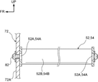
一対のテンションロール52、54は、前板72Aの上端部における左右方向中央部に左右に並んで取り付けられている。詳細に説明すると、図5に示されるように、テンションロール52、54は、軸部52A、54Aと軸部52A、54Aに対して回転自在に構成されたロール部52B、54Bとで構成されており、各軸部52A、54Aの軸方向一端部が取付ネジ82によって前板72Aの上端部に取り付けられている。
The pair of tension rolls 52, 54 are attached side by side to the central portion in the left-right direction at the upper end portion of the
なお、図3に示されるように、前板72Aには、その取付ネジ82の軸部を挿入可能な取付部の一例としての貫通孔72Cが複数形成されており、一対のテンションロール52、54の取付箇所が変更可能になっている。また、一対のテンションロール52、54は、各軸部52A、54Aの軸方向一端部だけが前板72Aに取り付けられるようになっており、その前板72Aで片持ち支持される構成になっている。
As shown in FIG. 3, the
<第1実施形態の作用>
以上のような構成とされた第1実施形態に係る退避手段70において、次にその作用について説明する。
<Action of the first embodiment>
Next, the operation of the evacuation means 70 according to the first embodiment having the above configuration will be described.
払拭部材60を交換する際には、まずロック機構を外し、前蓋72(前板72A)の上部を、そのボルト69を支点にして前方側へ引き出す。すると、一対のテンションロール52、54は、前蓋72(前板72A)の上端部に取り付けられているため、その前蓋72(前板72A)の上部の前方側への1つの引き出し動作に伴って前方側へ同時に引き出される(退避される)(図3、図4参照)。
When replacing the wiping
これにより、払拭部材60のテンションが低減されるため、払拭部材60の交換時の作業性が向上される。具体的には、一対のテンションロール52、54が、装置本体62から取り外し不能とされている払拭装置(図示省略)の場合や装置本体62から個別にしか取り外せない払拭装置(図示省略)の場合に比べて、払拭部材60を交換する作業時間が低減される。
As a result, the tension of the wiping
また、一対のテンションロール52、54の清掃又は交換を行うときには、前蓋72における側板72Bの下端部に形成されている切欠部73をボルト69の軸部から外す。つまり、前蓋72を装置本体62から取り外す。そして、その前蓋72における前板72Aからテンションロール52、54を取り外す。ここで、各テンションロール52、54は、図5に示されるように、前板72Aにネジ止めされているだけであるため、その前板72Aから容易に取り外せる。
Further, when cleaning or replacing the pair of tension rolls 52 and 54, the
また、このようにテンションロール52、54が、装置本体62に脱着可能な前蓋72に設けられていると、その前蓋72を作業し易い場所に持って行くことができるため、テンションロール52、54の清掃又は交換が容易に行える。よって、一対のテンションロール52、54が、装置本体62から取り外せない部材に設けられている場合に比べて、テンションロール52、54の清掃又は交換時の作業性が向上される。
Further, when the tension rolls 52 and 54 are provided on the
なお、実際には、払拭部材60の繰出方向下流側のテンションロール54が、払拭部材60で拭き取ったインク等で汚れることが多い。そのため、主にテンションロール54に対して清掃又は交換を行うことになる。また、テンションロール52、54は、前蓋72に設けられているため、前蓋72とは別のテンションロール52、54専用の脱着部材(図示省略)に設けられる場合に比べて、部品点数の低減が図れる。
In reality, the
こうして、テンションロール52、54の清掃又は交換が終了したら、前蓋72における側板72Bの下端部に形成されている切欠部73をボルト69の軸部に嵌合させる。そして、そのボルト69を支点にして前蓋72(前板72A)の上部を後方側へ押し戻し、装置本体62の前方側を前蓋72で閉じるとともに、その前蓋72が開かないようにロック機構によりロックする。この動作により、テンションロール52、54が払拭部材60に上方から同時に接触し、払拭部材60にテンションが掛かる。
When the cleaning or replacement of the tension rolls 52 and 54 is completed in this way, the
本実施形態では、上記の通り、テンションロール52、54の清掃又は交換が容易に行えるため、払拭部材60に対するテンション制御の精度が維持される。なお、装置本体62には、前蓋72が閉められたことを検知する検知手段80が設けられているため、テンションロール52、54の付け忘れが防止される。換言すれば、テンションロール52、54が配置されていない状態で払拭部材60が繰り出されることはない。
In the present embodiment, as described above, the tension rolls 52 and 54 can be easily cleaned or replaced, so that the accuracy of tension control for the wiping
また、上記の通り、テンションロール52、54は、容易に交換可能であるため、その位置の変更も容易に行える。すなわち、前板72Aには、テンションロール52、54を取り付けるための貫通孔72Cが複数形成されているため、払拭部材60の経路が変更された場合でも対応可能となる。
Further, as described above, since the tension rolls 52 and 54 can be easily replaced, their positions can be easily changed. That is, since the
また、テンションロール52、54の位置の変更だけではなく、インクやインクジェット記録ヘッド20の仕様の変更に伴って払拭部材60の材質が変更されたときなど、テンションロール52、54の材質を変更しなければならないときでも、その払拭部材60に適応したテンションロール52、54に容易に交換可能となる。
Further, not only the positions of the tension rolls 52 and 54 are changed, but also the materials of the tension rolls 52 and 54 are changed when the material of the wiping
<第2実施形態>
次に、退避手段70の第2実施形態について説明する。なお、上記第1実施形態と同等の部位には、同じ符号を付して詳細な説明は適宜省略する。また、図6、図7では洗浄液付与ノズル51の図示を省略する。
<Second Embodiment>
Next, a second embodiment of the evacuation means 70 will be described. The same parts as those in the first embodiment are designated by the same reference numerals, and detailed description thereof will be omitted as appropriate. Further, in FIGS. 6 and 7, the cleaning
図6、図7に示されるように、装置本体62の上側には、退避手段70を構成する蓋部材の一例としての上蓋74が設けられている。上蓋74は、矩形平板状の上板74Aと、その上板74Aの前後両側に一体に形成された矩形平板状の前板74B及び後板74Cと、を有しており、側面視で略逆「U」字状に形成されている。そして、この上蓋74は、装置本体62の上部に脱着可能に構成されている。したがって、この上蓋74は、脱着部材の一例でもある。
As shown in FIGS. 6 and 7, an
また、一対のテンションロール52、54が、その上蓋74に設けられている。詳細に説明すると、各テンションロール52、54は、その軸部52A、54A(図5参照)の軸方向一端部が前板74Bにネジ止めされ、軸方向他端部が後板74Cにネジ止めされている。これにより、一対のテンションロール52、54が、前板74Bと後板74Cとによって回転可能に支持される構成になっている。
Further, a pair of tension rolls 52 and 54 are provided on the
また、平面視で、上板74Aの一対のテンションロール52、54の間となる部分、即ち装置本体62に上蓋74を被せたときに、支持ロール50に巻き掛けられて支持された払拭部材60と上下方向で対向する部分には、矩形状の開口部75が形成されている。この開口部75により、装置本体62に上蓋74を被せたときに、支持ロール50に巻き掛けられて支持された払拭部材60が上方(ノズル面21)へ向けて突出可能となる構成になっている。
Further, in a plan view, the wiping
また、装置本体62(例えば後壁66)には、上蓋74が被せられたこと(閉じた状態に装着されたこと)を検知する検知手段80が設けられている。この検知手段80は、上記と同様であり、払拭装置40は、検知手段80で上蓋74が閉められたことを検知しないと、繰出モーターが回転駆動しないように構成されている。
Further, the apparatus main body 62 (for example, the rear wall 66) is provided with a detecting
なお、検知手段80としては、装置本体62(例えば後壁66)に設けられた被接触部材に、上蓋74に設けられた接触部材が接触することで、上蓋74の閉状態を検知する接触型のセンサーであってもよいし、装置本体62(例えば後壁66)に設けられた発光素子から出射される光を、上蓋74に設けられた受光素子が受光することで、上蓋74の閉状態を検知する非接触型のセンサー等であってもよい。
The detection means 80 is a contact type that detects the closed state of the
<第2実施形態の作用>
以上のような構成とされた第2実施形態に係る退避手段70において、次にその作用について説明する。なお、上記第1実施形態と共通する作用については適宜省略する。
<Action of the second embodiment>
Next, the operation of the evacuation means 70 according to the second embodiment having the above configuration will be described. The actions common to the first embodiment will be omitted as appropriate.
払拭部材60を交換する際には、上蓋74を装置本体62から取り外す。なお、このとき、上蓋74は、ガイド手段(図示省略)により、鉛直方向上側に真っ直ぐに取り外される。すると、一対のテンションロール52、54は、上蓋74に取り付けられているため、その上蓋74の上方側への1つの取り外し動作に伴って上方側へ同時に取り出される(退避される)(図6、図7参照)。
When replacing the wiping
これにより、払拭部材60のテンションが低減されるため、払拭部材60の交換時の作業性が向上される。具体的には、一対のテンションロール52、54が、装置本体62から取り外し不能とされている払拭装置(図示省略)の場合や装置本体62から個別にしか取り外せない払拭装置(図示省略)の場合に比べて、払拭部材60を交換する作業時間が低減される。
As a result, the tension of the wiping
また、一対のテンションロール52、54の清掃又は交換を行うときには、上蓋74からテンションロール52、54を取り外す。ここで、各テンションロール52、54は、前板74Bと後板74Cとにネジ止めされているだけであるため、その前板74Bと後板74Cから容易に取り外せる。
Further, when cleaning or replacing the pair of tension rolls 52 and 54, the tension rolls 52 and 54 are removed from the
また、このようにテンションロール52、54が、装置本体62に脱着可能な上蓋74に設けられていると、その上蓋74を作業し易い場所に持って行くことができるため、テンションロール52、54の清掃又は交換が容易に行える。よって、一対のテンションロール52、54が、装置本体62から取り外せない部材に設けられている場合に比べて、テンションロール52、54の清掃又は交換時の作業性が向上される。
Further, when the tension rolls 52 and 54 are provided on the
また、テンションロール52、54は、上蓋74に設けられているため、上蓋74とは別のテンションロール52、54専用の脱着部材(図示省略)に設けられる場合に比べて、部品点数の低減が図れる。
Further, since the tension rolls 52 and 54 are provided on the
こうして、テンションロール52、54の清掃又は交換が終了したら、上蓋74を装置本体62に被せる。この動作により、テンションロール52、54が払拭部材60に上方から同時に接触し、払拭部材60にテンションが掛かる。本実施形態では、上記の通り、テンションロール52、54の清掃又は交換が容易に行えるため、払拭部材60に対するテンション制御の精度が維持される。
In this way, when the cleaning or replacement of the tension rolls 52 and 54 is completed, the
なお、装置本体62には、上蓋74が被せられたことを検知する検知手段80が設けられているため、テンションロール52、54の付け忘れが防止される。換言すれば、テンションロール52、54が配置されていない状態で払拭部材60が繰り出されることはない。
Since the device
<第3実施形態>
次に、退避手段70の第3実施形態について説明する。なお、上記第1実施形態又は第2実施形態と同等の部位には、同じ符号を付して詳細な説明は適宜省略する。また、図8、図9では洗浄液付与ノズル51の図示を省略する。
<Third Embodiment>
Next, a third embodiment of the evacuation means 70 will be described. The same parts as those of the first embodiment or the second embodiment are designated by the same reference numerals, and detailed description thereof will be omitted as appropriate. Further, in FIGS. 8 and 9, the cleaning
図8、図9に示されるように、装置本体62の上部における一方(例えば右側)の角部には、退避手段70を構成する回転部材の一例としての一対のアーム部材76が回転可能に設けられている。
As shown in FIGS. 8 and 9, a pair of
詳細に説明すると、一対のアーム部材76の先端部には、払拭部材60の繰出方向上流側となるテンションロール52が回転可能に支持されている。すなわち、テンションロール52の軸部52A(図5参照)における軸方向一端部が前側(一方)のアーム部材76Aの先端部にネジ止めされ、軸方向他端部が後側(他方)のアーム部材76Bの先端部にネジ止めされている。
More specifically, a
また、一対のアーム部材76の中途部には、払拭部材60の繰出方向下流側となるテンションロール54が回転可能に支持されている。すなわち、テンションロール54の軸部54A(図5参照)における軸方向一端部が前側のアーム部材76Aの中途部にネジ止めされ、軸方向他端部が後側のアーム部材76Bの中途部にネジ止めされている。
Further, a
また、前側のアーム部材76Aの基端部76Cは、側壁68の上部から前蓋72側へ屈曲して一体に張り出した張出部68Aに、保持手段の一例としてのある程度の摩擦(摺動抵抗)Fを有して回転可能に支持されている。そして、後側のアーム部材76Bの基端部76Dは、後壁66の上部に、保持手段の一例としてのある程度の摩擦(摺動抵抗)Fを有して回転可能に支持されている。このような保持手段(摩擦F)により、一対のテンションロール52、54は、その上方位置にて保持可能になっている。
Further, the
また、張出部68Aと前後方向で対向する前蓋72の角部は略矩形状に切り欠かれている。つまり、前蓋72の角部には、正面視で略矩形状となる切欠部77が形成されている。この切欠部77により、前蓋72の開閉動作がアーム部材76によって阻害されない構成になっている。
Further, the corner portion of the
また、装置本体62には、アーム部材76の回転により一対のテンションロール52、54が払拭部材60に接触したことを検知する検知手段80が設けられている。換言すれば、装置本体62には、一対のテンションロール52、54が払拭部材60に接触した状態のときのアーム部材76の位置を検知する検知手段80が設けられている。
Further, the apparatus
この検知手段80も、上記と同様であり、払拭装置40は、検知手段80で一対のテンションロール52、54が払拭部材60に接触したこと(一対のテンションロール52、54が払拭部材60に接触した状態のときのアーム部材76の位置)を検知しないと、繰出モーターが回転駆動しないように構成されている。
The detection means 80 is also the same as described above, and in the
なお、検知手段80としては、装置本体62(例えば後壁66)に設けられた被接触部材に、アーム部材76に設けられた接触部材が接触することで、各テンションロール52、54の接触状態を検知する接触型のセンサーであってもよいし、装置本体62(例えば後壁66)に設けられた発光素子から出射される光を、アーム部材76に設けられた受光素子が受光することで、各テンションロール52、54の接触状態を検知する非接触型のセンサー等であってもよい。
The detection means 80 is such that the contact member provided on the
<第3実施形態の作用>
以上のような構成とされた第3実施形態に係る退避手段70において、次にその作用について説明する。なお、上記第1実施形態又は第2実施形態と共通する作用については適宜省略する。
<Action of the third embodiment>
Next, the operation of the evacuation means 70 according to the third embodiment having the above configuration will be described. The actions common to the first embodiment or the second embodiment will be omitted as appropriate.
払拭部材60を交換する際には、アーム部材76の基端部76C、76Dを支点にして、そのアーム部材76を上方へ向かって回転させる。すると、一対のテンションロール52、54は、そのアーム部材76の先端部及び中途部に取り付けられているため、その1つの回転動作に伴って上方へ向かって同時に持ち上げられる(退避される)(図8、図9参照)。
When replacing the wiping
そして、一対のテンションロール52、54は、アーム部材76の基端部76C、76Dに付与された摩擦(摺動抵抗)Fにより、その上方位置にて保持される。こうして、一対のテンションロール52、54が払拭部材60から同時に退避することにより、払拭部材60のテンションが低減されるため、払拭部材60の交換時の作業性が向上される。
The pair of tension rolls 52, 54 are held at an upper position by the friction (sliding resistance) F applied to the
具体的には、一対のテンションロール52、54が、払拭部材60に接触した状態のままで取り外し不能とされている払拭装置(図示省略)の場合や払拭部材60に接触した状態で個別にしか取り外せない払拭装置(図示省略)の場合に比べて、払拭部材60を交換する作業時間が低減される。
Specifically, in the case of a wiping device (not shown) in which the pair of tension rolls 52, 54 cannot be removed while in contact with the wiping
また、一対のテンションロール52、54は、装置本体62に回転可能に支持されたアーム部材76に設けられているため、一対のテンションロール52、54が、装置本体62から外れてしまう部材に設けられている場合に比べて、各テンションロール52、54の紛失が抑制又は防止される。
Further, since the pair of tension rolls 52 and 54 are provided on the
また、一対のテンションロール52、54の清掃又は交換を行うときには、保持手段(摩擦F)により上方位置にて保持されているアーム部材76からテンションロール52、54を取り外す。ここで、テンションロール52、54は、アーム部材76にネジ止めされているだけであるため、そのアーム部材76から容易に取り外せる。これにより、テンションロール52、54の清掃又は交換が容易に行える。すなわち、テンションロール52、54の清掃又は交換時の作業性が向上される。
Further, when cleaning or replacing the pair of tension rolls 52 and 54, the tension rolls 52 and 54 are removed from the
こうして、テンションロール52、54の清掃又は交換が終了したら、アーム部材76を下方へ向けて回転させる。これにより、テンションロール52、54が払拭部材60に上方から接触し、払拭部材60にテンションが掛かる。本実施形態では、上記の通り、テンションロール52、54の清掃又は交換が容易に行えるため、払拭部材60に対するテンション制御の精度が維持される。
In this way, when the cleaning or replacement of the tension rolls 52 and 54 is completed, the
なお、装置本体62には、一対のテンションロール52、54が払拭部材60に接触したこと(一対のテンションロール52、54が払拭部材60に接触した状態のときのアーム部材76の位置)を検知する検知手段80が設けられているため、テンションロール52、54の付け忘れが防止される。換言すれば、テンションロール52、54が配置されていない状態で払拭部材60が繰り出されることはない。
The apparatus
<第4実施形態>
最後に、退避手段70の第4実施形態について説明する。なお、上記第1実施形態~第3実施形態と同等の部位には、同じ符号を付して詳細な説明は適宜省略する。また、図10、図11では洗浄液付与ノズル51の図示を省略する。
<Fourth Embodiment>
Finally, a fourth embodiment of the evacuation means 70 will be described. The same parts as those of the first to third embodiments are designated by the same reference numerals, and detailed description thereof will be omitted as appropriate. Further, in FIGS. 10 and 11, the cleaning
図10、図11に示されるように、一対のテンションロール52、54の軸部52A、54A(図5参照)における軸方向一端部側には、軸部52Aと軸部54Aとを連結する連結部材78が設けられている。退避手段70を構成する連結部材78は、左右方向が長手方向とされた矩形平板状に形成されている。そして、連結部材78の長手方向中央部には、手指等で把持可能となるように、上方へ向けて突出する矩形平板状の突出部78Aが一体に形成されている。
As shown in FIGS. 10 and 11, the
なお、一対のテンションロール52、54を払拭部材60に接触させてテンションを掛けるときには、連結部材78は、支軸部材48の前方側へ配置されるようになっている。また、支軸部材48には、必要に応じて、各テンションロール52、54の軸方向一端部側の軸部52A、54Aを受け入れて支持する正面視略「U」字状の軸受部48A(図10参照)を形成するようにしてもよい。
When the pair of tension rolls 52 and 54 are brought into contact with the wiping
また、一対のテンションロール52、54の軸部52A、54Aにおける軸方向他端部は、支持部材の一例としてのボールジョイント84(図11参照)を介して支軸部材48に支持されている。これにより、一対のテンションロール52、54の軸部52A、54Aにおける軸方向一端部側、即ち連結部材78の上下方向への移動(上昇動作及び下降動作)が許容される構成になっている。
Further, the other end in the axial direction of the
また、装置本体62の一部である支軸部材48の前面には、連結部材78が、支軸部材48の前方側に配置されたこと(連結部材78の下方への移動により、一対のテンションロール52、54が払拭部材60に接触したこと)を検知する検知手段80が設けられている。
Further, on the front surface of the
この検知手段80も、上記と同様であり、払拭装置40は、検知手段80で一対のテンションロール52、54が払拭部材60に接触したこと(一対のテンションロール52、54が払拭部材60に接触した状態のときの連結部材78の位置)を検知しないと、繰出モーターが回転駆動しないように構成されている。
The detection means 80 is also the same as described above, and in the
なお、検知手段80としては、支軸部材48に設けられた被接触部材に、連結部材78に設けられた接触部材が接触することで、各テンションロール52、54の接触状態を検知する接触型のセンサーであってもよいし、支軸部材48に設けられた発光素子から出射される光を、連結部材78に設けられた受光素子が受光することで、各テンションロール52、54の接触状態を検知する非接触型のセンサー等であってもよい。
The detection means 80 is a contact type that detects the contact state of the tension rolls 52 and 54 by contacting the contacted member provided on the
<第4実施形態の作用>
以上のような構成とされた第4実施形態に係る退避手段70において、次にその作用について説明する。なお、上記第1実施形態~第3実施形態と共通する作用については適宜省略する。
<Action of the fourth embodiment>
Next, the operation of the evacuation means 70 according to the fourth embodiment having the above configuration will be described. The actions common to the first to third embodiments will be omitted as appropriate.
払拭部材60を交換する際には、連結部材78の突出部78Aを手指等で把持し、その連結部材78を上方へ向かって持ち上げる。すると、一対のテンションロール52、54は、各軸部52A、54Aの軸方向他端部がボールジョイント84によって支持されているため、各ボールジョイント84を支点にして、各軸部52A、54Aの軸方向一端部側が上方へ向かって同時に持ち上げられる(退避される)(図10、図11参照)。
When replacing the wiping
そして、一対のテンションロール52、54は、各ボールジョイント84の摺動抵抗により、その上方位置にて保持される。こうして、一対のテンションロール52、54が払拭部材60から同時に退避することにより、払拭部材60のテンションが低減されるため、払拭部材60の交換時の作業性が向上される。
The pair of tension rolls 52, 54 are held at an upper position by the sliding resistance of each ball joint 84. In this way, the pair of tension rolls 52 and 54 are retracted from the wiping
具体的には、一対のテンションロール52、54が、払拭部材60に接触した状態のままで取り外し不能とされている払拭装置(図示省略)の場合や払拭部材60に接触した状態で個別にしか取り外せない払拭装置(図示省略)の場合に比べて、払拭部材60を交換する作業時間が低減される。
Specifically, in the case of a wiping device (not shown) in which the pair of tension rolls 52, 54 cannot be removed while in contact with the wiping
また、一対のテンションロール52、54の清掃又は交換を行うときには、各ボールジョイント84からテンションロール52、54を取り外す。これにより、テンションロール52、54の清掃又は交換が容易に行える。すなわち、テンションロール52、54の軸部52A、54Aの軸方向他端部側がネジ止めされ、連結部材78が上下方向に移動不能とされている場合に比べて、テンションロール52、54の清掃又は交換時の作業性が向上される。
Further, when cleaning or replacing the pair of tension rolls 52 and 54, the tension rolls 52 and 54 are removed from the ball joints 84. This makes it easy to clean or replace the tension rolls 52 and 54. That is, the tension rolls 52 and 54 are cleaned or cleaned as compared with the case where the other ends of the
こうして、テンションロール52、54の清掃又は交換が終了したら、連結部材78が上方位置にて保持された状態となるように、テンションロール52、54の各軸部52A、54Aの軸方向他端部を各ボールジョイント84に取り付ける。そして、連結部材78を下降させ、支軸部材48の前方側に配置する。
In this way, when the cleaning or replacement of the tension rolls 52 and 54 is completed, the other ends of the
これにより、テンションロール52、54が払拭部材60に上方から同時に接触し、払拭部材60にテンションが掛かる。本実施形態では、上記の通り、テンションロール52、54の清掃又は交換が容易に行えるため、払拭部材60に対するテンション制御の精度が維持される。
As a result, the tension rolls 52 and 54 come into contact with the wiping
なお、支軸部材48には、連結部材78が前方側に配置されたこと、即ち一対のテンションロール52、54が払拭部材60に接触したことを検知する検知手段80が設けられているため、テンションロール52、54の付け忘れが防止される。換言すれば、テンションロール52、54が配置されていない状態で払拭部材60が繰り出されることはない。
Since the
以上、本実施形態に係る払拭装置40について、図面を基に説明したが、本実施形態に係る払拭装置40は、図示のものに限定されるものではなく、本発明の要旨を逸脱しない範囲内において、適宜設計変更可能なものである。例えば、一対のテンションロール52、54は、払拭部材60から退避するときには、同時であるが、払拭部材60に接触するときには、同時でなくてもよい。
The wiping
また、第3実施形態において、アーム部材76は、装置本体62の角部に設けられる構成に限定されるものではなく、例えば装置本体62の後部に設けられる構成とされていてもよい。すなわち、アーム部材76は、前後方向を回転軸として、左右方向に回転する構成に限定されるものではなく、左右方向を回転軸として、前後方向に回転する構成とされていてもよい。
Further, in the third embodiment, the
更に、第3実施形態において、アーム部材76を上方位置にて保持する保持手段は、基端部76C、76Dに付与された摩擦Fによるものに限定されるものではなく、例えばアーム部材76や装置本体62に設けられたストッパー機構(図示省略)などであってもよい。
Further, in the third embodiment, the holding means for holding the
また、本実施形態に係るインクジェット記録装置10は、複写機、プリンター複合機、ワークステーション等の出力機器として用いられる記録装置など、記録用紙P上への文字や画像の記録に用いられるものに限定されるものではなく、例えば、高分子フィルムやガラス上に着色インクを吐出して行うディスプレイ用のカラーフィルターの作製などにも適用することが可能である。
Further, the
すなわち、本実施形態における「記録媒体」には、記録用紙P以外に、例えばOHPシートや配線パターン等が形成される基板なども含まれる。そして、本実施形態における「画像」には、一般的な画像(文字、絵、写真等)のみならず、インク滴が記録媒体上に着弾されることで得られるドットのパターン(配線パターン)なども含まれる。 That is, the "recording medium" in the present embodiment includes, for example, a substrate on which an OHP sheet, a wiring pattern, or the like is formed, in addition to the recording paper P. The "image" in the present embodiment includes not only general images (characters, pictures, photographs, etc.) but also dot patterns (wiring patterns) obtained by landing ink droplets on a recording medium. Is also included.
10 インクジェット記録装置(液滴吐出装置の一例)
20 インクジェット記録ヘッド(液滴吐出ヘッドの一例)
21 ノズル面
40 払拭装置
42 繰出ロール
44 巻取ロール
50 支持ロール(第1ロールの一例)
52 テンションロール(第3ロールの一例)
54 テンションロール(第3ロールの一例)
56 ガイドロール(第2ロールの一例)
58 ガイドロール(第2ロールの一例)
60 払拭部材
62 装置本体(筐体の一例)
70 退避手段
72 前蓋(蓋部材の一例/脱着部材の一例)
74 上蓋(蓋部材の一例/脱着部材の一例)
76 アーム部材(回転部材の一例)
78 連結部材
80 検知手段
84 ボールジョイント(支持部材の一例)
10 Inkjet recording device (an example of a drop ejection device)
20 Inkjet recording head (an example of a droplet ejection head)
21
52 Tension roll (an example of the third roll)
54 Tension roll (an example of the third roll)
56 Guide roll (an example of the second roll)
58 Guide roll (an example of the second roll)
60 Wiping
70 Evacuation means 72 Front lid (example of lid member / example of removable member)
74 Top lid (example of lid member / example of removable member)
76 Arm member (example of rotating member)
78 Connecting
Claims (11)
前記払拭部材に下方から接触し、前記ノズル面に前記払拭部材を接触させる第1ロールと、
前記第1ロールにおける前記払拭部材の繰出方向上流側及び下流側に配置され、前記払拭部材に下方から接触する一対の第2ロールと、
前記第1ロールと前記一対の第2ロールとの間に配置され、前記払拭部材に上方から接触する一対の第3ロールと、
前記一対の第3ロールを前記払拭部材から同時に退避させる退避手段と、
前記払拭部材を繰り出す繰出ロールと前記払拭部材を巻き取る巻取ロールとが収容された筐体と、
を備え、
前記退避手段は、
前記一対の第3ロールを支持し、前記筐体に対して脱着される蓋部材で構成され、
前記蓋部材は、前記筐体における前記繰出ロールの軸方向一端部側に設けられている払拭装置。 A wiping member that wipes the nozzle surface of the droplet ejection head,
A first roll that comes into contact with the wiping member from below and brings the wiping member into contact with the nozzle surface.
A pair of second rolls arranged on the upstream side and the downstream side in the feeding direction of the wiping member in the first roll and in contact with the wiping member from below,
A pair of third rolls arranged between the first roll and the pair of second rolls and in contact with the wiping member from above,
An evacuation means for simultaneously retracting the pair of third rolls from the wiping member, and
A housing in which a feeding roll for feeding the wiping member and a winding roll for winding the wiping member are housed, and
Equipped with
The evacuation means is
It is composed of a lid member that supports the pair of third rolls and is attached to and detached from the housing.
The lid member is a wiping device provided on one end side in the axial direction of the feeding roll in the housing .
前記払拭部材に下方から接触し、前記ノズル面に前記払拭部材を接触させる第1ロールと、
前記第1ロールにおける前記払拭部材の繰出方向上流側及び下流側に配置され、前記払拭部材に下方から接触する一対の第2ロールと、
前記第1ロールと前記一対の第2ロールとの間に配置され、前記払拭部材に上方から接触する一対の第3ロールと、
前記一対の第3ロールを前記払拭部材から同時に退避させる退避手段と、
前記払拭部材を繰り出す繰出ロールと前記払拭部材を巻き取る巻取ロールとが収容された筐体と、
を備え、
前記退避手段は、
前記一対の第3ロールを支持し、前記筐体に対して脱着される蓋部材で構成され、
前記蓋部材は、前記筐体の上側に設けられている払拭装置。 A wiping member that wipes the nozzle surface of the droplet ejection head,
A first roll that comes into contact with the wiping member from below and brings the wiping member into contact with the nozzle surface.
A pair of second rolls arranged on the upstream side and the downstream side in the feeding direction of the wiping member in the first roll and in contact with the wiping member from below,
A pair of third rolls arranged between the first roll and the pair of second rolls and in contact with the wiping member from above,
An evacuation means for simultaneously retracting the pair of third rolls from the wiping member, and
A housing in which a feeding roll for feeding the wiping member and a winding roll for winding the wiping member are housed , and
Equipped with
The evacuation means is
It is composed of a lid member that supports the pair of third rolls and is attached to and detached from the housing .
The lid member is a wiping device provided on the upper side of the housing .
前記払拭部材に下方から接触し、前記ノズル面に前記払拭部材を接触させる第1ロールと、
前記第1ロールにおける前記払拭部材の繰出方向上流側及び下流側に配置され、前記払拭部材に下方から接触する一対の第2ロールと、
前記第1ロールと前記一対の第2ロールとの間に配置され、前記払拭部材に上方から接触する一対の第3ロールと、
前記一対の第3ロールを前記払拭部材から同時に退避させる退避手段と、
前記払拭部材を繰り出す繰出ロールと前記払拭部材を巻き取る巻取ロールとが収容された筐体と、
を備え、
前記退避手段は、
前記一対の第3ロールを支持し、前記筐体に対して脱着される脱着部材で構成され、
前記筐体は、前記脱着部材が装着されたことを検知する検知手段を有する払拭装置。 A wiping member that wipes the nozzle surface of the droplet ejection head,
A first roll that comes into contact with the wiping member from below and brings the wiping member into contact with the nozzle surface.
A pair of second rolls arranged on the upstream side and the downstream side in the feeding direction of the wiping member in the first roll and in contact with the wiping member from below,
A pair of third rolls arranged between the first roll and the pair of second rolls and in contact with the wiping member from above,
An evacuation means for simultaneously retracting the pair of third rolls from the wiping member, and
A housing in which a feeding roll for feeding the wiping member and a winding roll for winding the wiping member are housed, and
Equipped with
The evacuation means is
It is composed of a detachable member that supports the pair of third rolls and is detached from the housing.
The housing is a wiping device having a detecting means for detecting that the detachable member is attached .
前記払拭部材に下方から接触し、前記ノズル面に前記払拭部材を接触させる第1ロールと、
前記第1ロールにおける前記払拭部材の繰出方向上流側及び下流側に配置され、前記払拭部材に下方から接触する一対の第2ロールと、
前記第1ロールと前記一対の第2ロールとの間に配置され、前記払拭部材に上方から接触する一対の第3ロールと、
前記一対の第3ロールを前記払拭部材から同時に退避させる退避手段と、
前記払拭部材を繰り出す繰出ロールと前記払拭部材を巻き取る巻取ロールとが収容された筐体と、
を備え、
前記退避手段は、
前記一対の第3ロールを支持し、前記筐体に回転可能に支持された回転部材で構成されている払拭装置。 A wiping member that wipes the nozzle surface of the droplet ejection head,
A first roll that comes into contact with the wiping member from below and brings the wiping member into contact with the nozzle surface.
A pair of second rolls arranged on the upstream side and the downstream side in the feeding direction of the wiping member in the first roll and in contact with the wiping member from below,
A pair of third rolls arranged between the first roll and the pair of second rolls and in contact with the wiping member from above,
An evacuation means for simultaneously retracting the pair of third rolls from the wiping member, and
A housing in which a feeding roll for feeding the wiping member and a winding roll for winding the wiping member are housed , and
Equipped with
The evacuation means is
A wiping device that supports the pair of third rolls and is composed of a rotating member rotatably supported by the housing.
前記払拭部材に下方から接触し、前記ノズル面に前記払拭部材を接触させる第1ロールと、
前記第1ロールにおける前記払拭部材の繰出方向上流側及び下流側に配置され、前記払拭部材に下方から接触する一対の第2ロールと、
前記第1ロールと前記一対の第2ロールとの間に配置され、前記払拭部材に上方から接触する一対の第3ロールと、
前記一対の第3ロールを前記払拭部材から同時に退避させる退避手段と、
前記払拭部材を繰り出す繰出ロールと前記払拭部材を巻き取る巻取ロールとが収容された筐体と、
を備え、
前記退避手段は、
前記一対の第3ロールの軸方向一端部側を連結する連結部材と、
前記筐体に設けられ、前記連結部材が上下方向に移動可能となるように、前記一対の第3ロールの軸方向他端部側を支持する支持部材と、
を有する払拭装置。 A wiping member that wipes the nozzle surface of the droplet ejection head,
A first roll that comes into contact with the wiping member from below and brings the wiping member into contact with the nozzle surface.
A pair of second rolls arranged on the upstream side and the downstream side in the feeding direction of the wiping member in the first roll and in contact with the wiping member from below,
A pair of third rolls arranged between the first roll and the pair of second rolls and in contact with the wiping member from above,
An evacuation means for simultaneously retracting the pair of third rolls from the wiping member, and
A housing in which a feeding roll for feeding the wiping member and a winding roll for winding the wiping member are housed , and
Equipped with
The evacuation means is
A connecting member that connects one end side of the pair of third rolls in the axial direction,
A support member provided on the housing and supporting the other end side in the axial direction of the pair of third rolls so that the connecting member can move in the vertical direction.
Wiping device with .
前記払拭装置に対して相対的に移動する液滴吐出ヘッドと、
を備えた液滴吐出装置。 The wiping device according to any one of claims 1 to 10,
A droplet ejection head that moves relative to the wiping device,
A drop ejection device equipped with.
Priority Applications (1)
| Application Number | Priority Date | Filing Date | Title |
|---|---|---|---|
| JP2017181221A JP7013763B2 (en) | 2017-09-21 | 2017-09-21 | Wiping device and droplet ejection device |
Applications Claiming Priority (1)
| Application Number | Priority Date | Filing Date | Title |
|---|---|---|---|
| JP2017181221A JP7013763B2 (en) | 2017-09-21 | 2017-09-21 | Wiping device and droplet ejection device |
Publications (2)
| Publication Number | Publication Date |
|---|---|
| JP2019055528A JP2019055528A (en) | 2019-04-11 |
| JP7013763B2 true JP7013763B2 (en) | 2022-02-01 |
Family
ID=66105931
Family Applications (1)
| Application Number | Title | Priority Date | Filing Date |
|---|---|---|---|
| JP2017181221A Active JP7013763B2 (en) | 2017-09-21 | 2017-09-21 | Wiping device and droplet ejection device |
Country Status (1)
| Country | Link |
|---|---|
| JP (1) | JP7013763B2 (en) |
Families Citing this family (1)
| Publication number | Priority date | Publication date | Assignee | Title |
|---|---|---|---|---|
| CN110449306B (en) * | 2019-09-09 | 2024-06-14 | 深圳市鹏创达自动化有限公司 | Rubber structure and dispensing equipment |
Citations (4)
| Publication number | Priority date | Publication date | Assignee | Title |
|---|---|---|---|---|
| JP2003118875A (en) | 2001-10-18 | 2003-04-23 | Matsushita Graphic Communication Systems Inc | Paper conveying device and electrophotographic recorder |
| JP2005294948A (en) | 2004-03-31 | 2005-10-20 | Canon Inc | Reading and recording apparatus |
| JP2008110831A (en) | 2006-10-30 | 2008-05-15 | Fuji Xerox Co Ltd | Roll support structure, paper sheet feed cassette, and sheet conveyer |
| JP2010241127A (en) | 2009-03-19 | 2010-10-28 | Fujifilm Corp | Inkjet recording apparatus |
Family Cites Families (6)
| Publication number | Priority date | Publication date | Assignee | Title |
|---|---|---|---|---|
| JPS63112042U (en) * | 1987-01-14 | 1988-07-19 | ||
| JPH0312247A (en) * | 1989-06-12 | 1991-01-21 | Matsushita Refrig Co Ltd | Air purifying device |
| JPH0313347A (en) * | 1989-06-13 | 1991-01-22 | Canon Inc | Liquid jet recorder |
| JPH082064A (en) * | 1994-06-23 | 1996-01-09 | Tec Corp | Cover on-off sensing device for electronic equipment |
| JPH09120195A (en) * | 1995-10-24 | 1997-05-06 | Ricoh Co Ltd | Image producing cartridge for image forming device |
| JP3886982B2 (en) * | 2004-03-31 | 2007-02-28 | アンリツ株式会社 | Signal generator for moving body test |
-
2017
- 2017-09-21 JP JP2017181221A patent/JP7013763B2/en active Active
Patent Citations (4)
| Publication number | Priority date | Publication date | Assignee | Title |
|---|---|---|---|---|
| JP2003118875A (en) | 2001-10-18 | 2003-04-23 | Matsushita Graphic Communication Systems Inc | Paper conveying device and electrophotographic recorder |
| JP2005294948A (en) | 2004-03-31 | 2005-10-20 | Canon Inc | Reading and recording apparatus |
| JP2008110831A (en) | 2006-10-30 | 2008-05-15 | Fuji Xerox Co Ltd | Roll support structure, paper sheet feed cassette, and sheet conveyer |
| JP2010241127A (en) | 2009-03-19 | 2010-10-28 | Fujifilm Corp | Inkjet recording apparatus |
Also Published As
| Publication number | Publication date |
|---|---|
| JP2019055528A (en) | 2019-04-11 |
Similar Documents
| Publication | Publication Date | Title |
|---|---|---|
| JP6620509B2 (en) | Printing device | |
| US9108442B2 (en) | Image forming apparatus | |
| JP4640067B2 (en) | Droplet discharge device | |
| US10449767B2 (en) | Liquid ejecting apparatus and cleaning device | |
| JP5782732B2 (en) | Image forming apparatus | |
| JP5467117B2 (en) | Liquid ejection apparatus, liquid ejection head cleaning apparatus, and ink jet recording apparatus | |
| JP7010047B2 (en) | Head cleaning device and liquid discharge device | |
| US8308270B2 (en) | Image forming apparatus | |
| JP4492366B2 (en) | Inkjet recording device | |
| JP2007054999A (en) | Droplet ejector, and carrying-member cleaning method therefor | |
| US20130194346A1 (en) | Image forming apparatus | |
| JP7013763B2 (en) | Wiping device and droplet ejection device | |
| JP2007131372A (en) | Ink jet recording device | |
| JP2007210131A (en) | Liquid droplet discharge device | |
| JP2012139829A (en) | Image forming apparatus | |
| JP7009872B2 (en) | Nozzle surface wiping device and droplet ejection device for droplet ejection head | |
| JP4968173B2 (en) | Droplet discharge device | |
| US20090141066A1 (en) | Recording Device | |
| JP2007190766A (en) | Droplet ejector | |
| JP7003529B2 (en) | Nozzle surface wiping method of droplet ejection head, nozzle surface wiping device and droplet ejection device | |
| JP2009148967A (en) | Liquid-droplet discharge apparatus | |
| JP2019147290A (en) | Ink jet printer | |
| JP2006264180A (en) | Image recording device | |
| JP5180878B2 (en) | Fluid ejection device and fluid ejection device cleaning method | |
| JP7326883B2 (en) | Inkjet recording device |
Legal Events
| Date | Code | Title | Description |
|---|---|---|---|
| A621 | Written request for application examination |
Free format text: JAPANESE INTERMEDIATE CODE: A621 Effective date: 20200831 |
|
| A977 | Report on retrieval |
Free format text: JAPANESE INTERMEDIATE CODE: A971007 Effective date: 20210615 |
|
| A131 | Notification of reasons for refusal |
Free format text: JAPANESE INTERMEDIATE CODE: A131 Effective date: 20210629 |
|
| A521 | Request for written amendment filed |
Free format text: JAPANESE INTERMEDIATE CODE: A523 Effective date: 20210811 |
|
| TRDD | Decision of grant or rejection written | ||
| A01 | Written decision to grant a patent or to grant a registration (utility model) |
Free format text: JAPANESE INTERMEDIATE CODE: A01 Effective date: 20211221 |
|
| A61 | First payment of annual fees (during grant procedure) |
Free format text: JAPANESE INTERMEDIATE CODE: A61 Effective date: 20220103 |