JP2005294948A - Reading and recording device - Google Patents
Reading and recording device Download PDFInfo
- Publication number
- JP2005294948A JP2005294948A JP2004103390A JP2004103390A JP2005294948A JP 2005294948 A JP2005294948 A JP 2005294948A JP 2004103390 A JP2004103390 A JP 2004103390A JP 2004103390 A JP2004103390 A JP 2004103390A JP 2005294948 A JP2005294948 A JP 2005294948A
- Authority
- JP
- Japan
- Prior art keywords
- recording
- reading
- opening
- unit
- reading unit
- Prior art date
- Legal status (The legal status is an assumption and is not a legal conclusion. Google has not performed a legal analysis and makes no representation as to the accuracy of the status listed.)
- Pending
Links
Images

Landscapes
- Accessory Devices And Overall Control Thereof (AREA)
- Facsimiles In General (AREA)
Abstract
Description
本発明は、プリンタ、複写機、印刷装置、ファクシミリ及びスキャナ等を含む画像形成装置及び画像読取装置等において、記録部と読取部とを備えた読取記録装置に関する。 The present invention relates to a reading and recording apparatus including a recording unit and a reading unit in an image forming apparatus and an image reading apparatus including a printer, a copier, a printing apparatus, a facsimile, a scanner, and the like.
プリンタ、複写機、印刷装置、ファクシミリ及びスキャナ等を含む画像形成装置から成る記録部と、原稿を読み取る画像読取装置等から成る読取部とを備えた読取記録装置として、一体型の外装の内部に、記録部(記録装置)の上部に読取部(フラットベットスキャナ等の読取装置)を配置した構成体を収容したものが使用されている。上記記録部は、カセットに積載された被記録材としてのシート材を給紙機構によって記録領域へ給送し、記録領域で移動(走査)可能に装着された記録ヘッドを画像情報に基づいて駆動することによりシート材に記録し、記録されたシート材を排紙トレイ等の排紙領域へ排出するように構成されている。一方、上記読取部は、CCDセンサ等を有する読取手段によって原稿台上の原稿を読み取り、読み取った画像情報を取り出し可能な状態で蓄積するように構成されている。そして、記録部と該記録部の上面部に装着される読取部とを重ね合わせた状態で一体型の外装の内部に配設することにより、読取記録装置が構成されている。 As a reading / recording device comprising a recording unit comprising an image forming apparatus including a printer, a copier, a printing device, a facsimile, a scanner, etc., and a reading unit comprising an image reading device for reading an original, etc. In this case, a housing in which a structure in which a reading unit (reading device such as a flat bed scanner) is arranged at the upper part of a recording unit (recording device) is used. The recording section feeds a sheet material as a recording material stacked in a cassette to a recording area by a paper feeding mechanism, and drives a recording head mounted so as to be movable (scanning) in the recording area based on image information In this way, recording is performed on the sheet material, and the recorded sheet material is discharged to a discharge area such as a discharge tray. On the other hand, the reading unit is configured to read a document on a document table by reading means having a CCD sensor or the like, and to store the read image information in a state where it can be taken out. Then, the reading and recording apparatus is configured by arranging the recording unit and the reading unit mounted on the upper surface portion of the recording unit in an integrated exterior in an overlapped state.
図5は上述の読取記録装置の全体構成の外観を示す模式的斜視図であり、図6は図5の読取記録装置の記録部の内部構成を示す模式的斜視図であり、図7は図5の読取記録装置において原稿カバーを外して読取部の内部構成を示す模式的平面図である。図5〜図7の読取記録装置は1つの外装で記録部と読取部を覆った構成を有している。図5において、100は記録部、200は読取部、101は記録のためのシート材を積載するカセット、102は排出されたシート材を受けるための排紙領域であり、201は読取部で読み取るための原稿を載置するための原稿台(原稿載置台)、202は原稿台上の原稿を覆って保持するための原稿カバーである。
FIG. 5 is a schematic perspective view showing the external appearance of the overall configuration of the above-described reading and recording apparatus, FIG. 6 is a schematic perspective view showing the internal configuration of the recording unit of the reading and recording apparatus in FIG. 5, and FIG. 6 is a schematic plan view illustrating an internal configuration of a reading unit with a document cover removed in the reading and recording apparatus of FIG. 5 to 7 has a configuration in which the recording unit and the reading unit are covered with one exterior. In FIG. 5, 100 is a recording unit, 200 is a reading unit, 101 is a cassette for stacking sheet materials for recording, 102 is a discharge area for receiving discharged sheet materials, and 201 is read by the reading unit. An original platen (original platen) 202 for placing an original for printing and an
図6及び図7において、給紙機構の給紙ローラ(不図示)を駆動することによりカセット101内から分離給送された1枚のシート材は、複数の中間ローラ(不図示)によって、キャリッジ104に搭載された記録手段105に対向する位置に設置されたプラテン106上にUターン搬送される。キャリッジ104は、キャリッジモータ107の駆動をタイミングベルト108を介して受けることで駆動され、ガイドシャフト109及びガイドレール110に沿って主走査方向(図示の例ではシート材搬送方向と交差する方向)に平行に往復駆動される。キャリッジ104に搭載された記録手段105は、該キャリッジの背面側に設けられたキャリッジ基板114を介して可撓性ケーブル(フレキシブルケーブル)111により、装置本体側に装着された制御基板150と接続されている。キャリッジ104の位置制御に同期して記録手段105を記録データに基づいて駆動することにより、プラテン106上のシート材に画像が記録される。
6 and 7, one sheet material separated and fed from inside the
キャリッジモータ107としては、DCモータやステッピングモータなどが使用される。そして、キャリッジ107の位置制御においては、装置本体側に設置されたリニアスケール112のスリット(1インチあたり300スリット等)をキャリッジ基板114上のエンコーダセンサ(不図示)で検知することによりフィードバック制御を行っている。このような制御により、キャリッジ104の正確な速度(位置)制御と低速から高速までの静かで安定した駆動とを可能としている。また、キャリッジ104は、種々の厚さのシート材に対する記録を可能とするため、昇降可能に構成されている。キャリッジ104及び記録手段105の昇降は、昇降モータ113で駆動されるカム手段によりガイドシャフト109を矢印Z方向に昇降させることで行われる。すなわち、シート材の厚さに応じて記録手段105を該シート材の厚み方向に移動させるための移動手段が設けられている。以上により、1ラインずつの記録とシート材の搬送とを交互に繰り返すことでシート材全体に対する記録を行い、記録されたシート材を排紙領域102へ排紙する構成の記録部100が構成されている。
As the
図5及び図7において、読取部200の上面には、ガラス板等で構成された原稿台(原稿載置台)201と、原稿を覆うための開閉可能な原稿カバー202とが設けられている。原稿台201の下部には、ガイドシャフト204に沿って往復移動可能に案内支持された読取手段としての読取ユニット203が設けられている。この読取ユニット203は、その両端部でをガイドレール(不図示)によって案内支持されている。読取ユニット203にはCCDセンサ等の読取手段が搭載されている。この読取ユニット203は、可撓性ケーブルから成る電気接続手段によって装置本体側の制御基板(記録部と共通)に接続され、読取モータ205の駆動によりタイミングベルト206を介して移動することで原稿の全体を読み取るように構成されている。読取モータ205としてはDCモータやステッピングモータなどが使用される。制御容易性の点ではステッピングモータに分が有り、精度及び静粛性の点ではDCモータに分が有る。以上により、原稿からの読み取りデータ、並びにホスト機器から送られるデータに基づく記録が可能な読取記録装置が構成されている。
5 and 7, an upper surface of the
以上図5〜図7を用いて説明した読取記録装置においては、キャリッジ104とともに記録手段105を移動させるための駆動手段(キャリッジモータ)107、並びに読取手段(読取ユニット)203を移動させるための駆動手段(読取モータ)205は、いずれも、エンコーダセンサ等による位置検出に基づいて制御されるモータで構成されている。また、上記記録手段105を移動させるための駆動伝動手段、並びに上記読取手段203を移動させるための駆動伝動手段は、いずれも、図示のようなタイミングベルト108、206もしくはワイヤ(不図示)により駆動力を伝達するように構成されている。以上説明した読取記録装置を開示する文献として、例えば特開2004−25588号公報を挙げることができる。
このように記録部と読取部を一体型の外装の内部に配置した従来の読取記録装置においては、記録のためのインクなどの消耗材を交換したり、シート材の紙詰まりを解消したりする際に、上部の読取部全体を回動(開閉)させて作業するか、記録部の正面側からのアクセスで対応するように構成されている。しかしながら、前者の読取部を回動させる構成の場合には、読取部全体を持ち上げることになるため、操作性に難点がある他に、ヒンジ(回動中心)周りの構造、持ち上げたときのロック構造、記録部と読取部を分離するための外装構造などが必要になり、装置構成が複雑になり、大型化及びコストアップを招くという不都合があった。 As described above, in the conventional reading and recording apparatus in which the recording unit and the reading unit are arranged inside the integrated outer casing, a consumable material such as ink for recording is replaced, or a paper jam in the sheet material is eliminated. At this time, it is configured to work by rotating (opening / closing) the entire upper reading unit or by accessing from the front side of the recording unit. However, in the case of the configuration in which the former reading unit is rotated, since the entire reading unit is lifted, there are difficulties in operability, the structure around the hinge (rotation center), the lock when being lifted The structure, an exterior structure for separating the recording unit and the reading unit are required, and the apparatus configuration is complicated, resulting in an increase in size and cost.
一方、後者の記録部の正面側からのアクセスで対応する場合には、装置が机上に置かれているようなときに、大きく屈み込んで作業したり、狭いスペースに手を挿入することになるため、操作性が不十分であるという不都合があった。これは、特に記録部の小型化が進行している現在において顕著であり、装置の小型化が阻害される要因にもなっている。本発明はこのような技術的課題に鑑みてなされたものであり、本発明の目的は、小型化及びコストダウンを図りながら操作性の向上を実現できる読取記録装置を提供することである。 On the other hand, when handling the latter from the front side of the recording unit, when the device is placed on a desk, it will be bent greatly and work will be inserted in a narrow space For this reason, there is an inconvenience that the operability is insufficient. This is particularly noticeable at the present time when the size of the recording unit is being reduced, and is a factor that hinders the size reduction of the apparatus. The present invention has been made in view of such a technical problem, and an object of the present invention is to provide a reading and recording apparatus capable of improving operability while reducing the size and cost.
本発明は、上記目的を達成するため、記録手段によりシート材に記録を行う記録部と、読取手段により原稿を読み取る読取部と、を備えた読取記録装置において、装置外部から前記読取部の内部へ至る第1の開口部と前記読取部の内部から前記記録部の内部へ至る第2の開口部とを設け、前記第1の開口部に移動可能な蓋部材を設け、該蓋部材を前記読取部の内部へ向けて移動させることにより装置外部から前記記録部の内部へアクセス可能にしたことを特徴とする。 In order to achieve the above object, the present invention provides a reading and recording apparatus comprising: a recording unit that records on a sheet material by a recording unit; and a reading unit that reads a document by a reading unit. A first opening extending from the reading unit to the recording unit, and a movable lid member is provided in the first opening. It is characterized in that the inside of the recording unit can be accessed from the outside of the apparatus by moving toward the inside of the reading unit.
また、本発明は、上記目的を達成するため、記録手段によりシート材に記録を行う記録部と、読取手段により原稿を読み取る読取部と、を備えた読取記録装置において、装置外部から前記読取部の内部へ至る開閉可能な第1の開口部と前記読取部の内部から前記記録部の内部へ至る第2の開口部とを設け、前記第1の開口部を開口させることにより装置外部から第1及び第2の開口部を通して前記記録部へアクセス可能にしたことを特徴とする。 In order to achieve the above object, the present invention provides a reading and recording apparatus comprising: a recording unit that records on a sheet material by a recording unit; and a reading unit that reads a document by a reading unit. A first opening that can be opened and closed to the inside of the image forming apparatus and a second opening that extends from the inside of the reading unit to the inside of the recording unit, and opening the first opening allows the first opening from the outside of the apparatus. The recording unit can be accessed through the first and second openings.
上記構成の本発明の読取記録装置によれば、小型化及びコストダウンを図りながら操作性の向上を実現できる読取記録装置が提供される。 According to the reading and recording apparatus of the present invention configured as described above, a reading and recording apparatus that can improve operability while reducing the size and cost is provided.
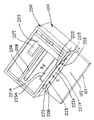
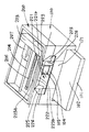
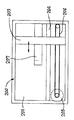
以下、図面を参照して本発明の実施形態を具体的に説明する。なお、各図面を通して同一符号は同一又は対応部分を示すものである。図1は本発明による読取記録装置の第1の実施形態の開口部を閉じたときの要部構成を示す模式的斜視図であり、図2は図1の読取記録装置の開口部を開いたときの要部構成を示す模式的斜視図であり、図3は図1の読取記録装置の開口部を開いたときの要部構成を図1と異なる方向から見た模式的斜視図である。図1〜図3において、100は記録部、200は読取部、101は記録のためのシート材を積載するカセット、102は排出されたシート材を受けるための排紙領域である。本実施形態においても、読取部200の上面には、図5の場合と同様、読取部で読み取るための原稿を載置するための原稿台(原稿載置台)201、原稿台上の原稿を覆って保持するための原稿カバー202が設けられている。
Embodiments of the present invention will be specifically described below with reference to the drawings. Note that the same reference numerals denote the same or corresponding parts throughout the drawings. FIG. 1 is a schematic perspective view showing the configuration of the main part when the opening of the first embodiment of the reading and recording apparatus according to the present invention is closed, and FIG. 2 is a view showing the opening of the reading and recording apparatus of FIG. 3 is a schematic perspective view showing the main part configuration at the time, and FIG. 3 is a schematic perspective view showing the main part configuration when the opening of the reading and recording apparatus in FIG. 1 is opened from a direction different from FIG. 1 to 3,
以下、本実施形態の記録部100及び読取部200の特徴的な構成について詳細に説明する。なお、本実施形態は、以下に説明する点を除いて、図5〜図7で説明した記録部100及び読取部200と実質的に同じ構成を有しており、それぞれ対応する部分が同一符号で示されている。図1〜図3において、読取記録装置には、読取部200の内部から記録部100の内部へ至る水平開口部221aと、外装部の前面に形成されて読取部200の内部を装置外部へ開放させるための垂直開口部221bとを有し、これらの開口部221a、221bを連続させて形成された開口部221が設けられている。この開口部221は、外装部の垂直開口部221bの上縁に沿って設けられた回転中心222の回りで回転可能(揺動可能)な蓋部材223によって開閉可能に構成されている。前記蓋部材223には、通常状態(図1の開口部221を閉じた状態)で前記水平開口部221aを覆って閉鎖する水平蓋部223aと、同じく通常状態で前記垂直開口部221bを覆って閉鎖する垂直蓋部223bとが一体に設けられている。
Hereinafter, characteristic configurations of the
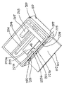
蓋部材223は、矢印B方向にばね付勢されており、通常状態では図1に示すような開口部221を覆う閉鎖位置に保持されている。前記開口部221を開く場合は、ユーザが装置前面から垂直蓋部223bを装置内部へ向けて矢印X方向へ押し込むことにより、蓋部材223が付勢ばね力に抗して回転中心222を中心に内方へ回転し、水平蓋部223bが矢印A方向へスライドする。そして、蓋部材223を矢印A方向へ十分に押し込むことにより、前記開口部221の垂直開口部221b及び水平開口部221aが同時に開口させられる(開放される)。そして、蓋部材223は、回転中心222周りのフリクションによって軽ロック状態となっているため、手を離して押し力を無くしても開放位置に静止状態で保持される。つまり、装置前面から垂直蓋部223bを押すだけで図1の閉鎖状態から図2及び図3の開放状態にすることができる。一方、前記開口部221を閉じる場合は、蓋部材223を図2及び図3の開放状態から軽く引き戻すだけで、蓋部材223を戻り方向へ回転させ、水平蓋部223bを矢印B方向へスライドさせることで図1の閉鎖状態に戻すことができる。
The
以上の構成によれば、通常状態では、蓋部材223によって開口部221を覆って閉鎖することで、記録部100と読取部200を別空間にし、読取部200と装置外部とを別空間にするとともに、読取部200内を閉空間にすることにより、記録部100の内部及び読取部200の内部へのゴミ等の異物の侵入が防止(阻止)されている。そして、記録のためのインクなどの消耗材の交換、シート材の紙詰まり解消などの保守点検操作を行う際には、蓋部材223を押すだけの簡単な操作で開口部221を開口させることにより、記録部100の内部へ容易にアクセスすることができる。
According to the above configuration, in the normal state, the
以下、第1の実施形態について更に詳細かつ具体的に説明する。図1〜図3において、蓋部材223は、回転中心222によって読取部200の外装部に対し回転可能に支持されるとともに、その垂直蓋部223bの両側に弾性的に曲げ(屈曲)可能な稜線224が設けられている。一方、蓋部材223は、通常状態では、その水平蓋部223aが読取部200の内部の底面に位置することで、読取部200と記録部100との間の開口部(水平開口部)221aを覆うとともに、矢印A及び矢印B方向にスライド可能に支持されている。蓋部材223は矢印B方向にばね付勢されている。さらに、蓋部材223の端部にマイクロスイッチ等のセンサ(不図示)を設けることにより、蓋部材223の開閉状態を検出できるように構成されている。
Hereinafter, the first embodiment will be described in more detail and specifically. 1 to 3, the
また、読取手段(読取ユニット)203が開口部221を避けた位置にあるときにのみ蓋部材223が開閉可能(開放可能)となるようなロック機構(不図示)が設けられている。記録のためのインクなどの消耗材を交換したり、シート材の紙詰まりを解消するなどの保守点検作業を行う際には、蓋部材223(その水平蓋部223b)を押すことによって、回転中心222を中心に該蓋部材223を回転させて該蓋部材223を矢印A方向に移動させる。その際、蓋部材223(その垂直蓋部223b)の両端部225も、それぞれの稜線部226によって曲がり(屈曲し)ながら読取部200の内部へ移動可能であり、蓋部材223を完全に押し込むと図2及び図3に示すような状態になる。
In addition, a lock mechanism (not shown) is provided so that the
図2及び図3の開放状態では、蓋部材223が読取ユニット203の移動領域に入り込んでおり、読取ユニット203の読み取りのための移動は不可能である。また、この開放状態では、読取部200の内部は、開口部221に対して、蓋部材223の両端部225によって両サイド(両側部位)を覆われた状態になり、前記垂直蓋部223bによって下面(底面)を覆われた状態になる。こうして、読取部200は、蓋部材223を押して開口部221が露出する前と同様に、閉空間の状態に維持されている。さらに、この開放状態では、蓋部材223は、回転中心222周りのフリクション(摩擦)によって軽いロック状態となっており、手を離してもばね付勢力だけでは閉じ位置へ復帰せず、静止可能な状態になっている。蓋部材223を元の閉じ位置に戻す際は、手前側へ引いてフリクションを解除してやることで、該蓋部材223の付勢ばね力によって戻すことができる。
In the open state of FIGS. 2 and 3, the
また、本実施形態においては、蓋部材223を押した状態では、開口部221が露出する(開放される)とともに、蓋部材223の開閉状態を検知するセンサ信号によって記録手段(記録ヘッド)105を搭載したキャリッジ104が開口部221の中央部に移動することで、記録部100に対するインク交換や紙詰まり解消のための作業を容易に行うことができるように構成されている。さらに、図3中に示すように記録部100の外装部の一部を開閉可能な扉構成121とすれば、シート材の紙詰まり解消等の作業を非常に容易に行うことが可能となり、一層の操作性向上を図ることができる。従って、図1〜図3の第1の実施形態によれば、装置外部から記録部100の内部に至る開閉可能な開口部221を形成することで、小型化及びコストダウンを図りながら操作性の向上を実現できる読取記録装置が提供される。
In this embodiment, when the
図1〜図3を用いて説明した第1の実施形態においては、記録手段によりシート材に記録を行う記録部と、読取手段により原稿を読み取る読取部と、を備えた読取記録装置において、装置外部から読取部200の内部へ至る第1の開口部221bと読取部200の内部から記録部100の内部へ至る第2の開口部221aとを設け、第1の開口部221bに移動可能な蓋部材223を設け、蓋部材223を読取部200の内部へ向けて移動させることにより装置外部から記録部100の内部へアクセス可能に構成されている。そして、第1の開口部221bと第2の開口部221aは共通の(図示の例では1つの)開口部221によって形成されている。
In the first embodiment described with reference to FIGS. 1 to 3, a reading and recording apparatus including a recording unit that records on a sheet material by a recording unit and a reading unit that reads a document by a reading unit. A
また、第1の開口部221bの開閉状態を検知可能とし、開状態であることを検知したとき、記録手段105を第2の開口部221aからアクセス可能な位置へ移動させるように構成されている。また、蓋部材223を読取部200の内部へ移動させて第1の開口部221bを開いたとき、読取部200の内部を蓋部材223によって閉空間とするように構成されている。さらに、蓋部材223を読取部200の内部へ移動させて第1の開口部221bを開くとき、読取手段200を蓋部材223と干渉しない位置に静止させるように構成されている。
In addition, the open / close state of the
なお、本発明は以上の第1の実施形態に限定されるものではなく、特許請求の範囲の記載による全ての構成をその範囲内に含むものである。例えば、本実施形態では、読取記録装置の前面側に開口部221を設ける構成としたが、これは側面あるいは背面側に開口部を設ける構成にしてもよい。また、開口部221を開けた状態で読取部200内を閉空間に維持するために、蓋部材223に曲げ(屈曲)可能な稜線部226を設ける場合を例示したが、これは、ゴムシートなどの弾性部材を用いて同様の機能効果を実現するように構成してもよい。
In addition, this invention is not limited to the above 1st Embodiment, All the structures by description of a claim are included in the range. For example, in the present embodiment, the
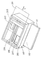
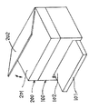
図4は本発明を適用した読取記録装置の実施例2の開口部を開いたときの要部構成を示す模式的斜視図である。以下に、図4を用いて、第2の実施形態の特徴的な構成について詳細に説明する。なお、本実施形態は、以下に説明する点を除いて、図5〜図7で説明した記録部100及び読取部200と実質的に同じ構成を有しており、それぞれ対応する部分が同一符号で示されている。図4において、記録部100は、図1〜図3の第1の実施形態の場合と実質的に同じ構成をしており、読取部200においては、読取手段としての読取ユニット203のCCD等の読取素子の周辺部に、ゴミ等の侵入を防止(阻止)するためのシール材(不図示)が設けられており、ゴミ等による不具合発生を防止又は軽減した構成が採られている。
FIG. 4 is a schematic perspective view showing the configuration of the main part when the opening of Example 2 of the reading and recording apparatus to which the present invention is applied is opened. The characteristic configuration of the second embodiment will be described below in detail with reference to FIG. The present embodiment has substantially the same configuration as the
また、ガラス板等で構成される原稿台(原稿載置台)201は矢印C方向にスライド(開閉)可能になっている。図4中の2点鎖線は、読取可能な状態から原稿台201を開放位置までスライド(移動)させた状態を示している。この場合の原稿台201のスライド量は図示の開き位置程度までの移動量に制限されており、開き位置でもユーザが読取ユニット203や電気接続手段(フレキシブルケーブルやフラットケーブル等の可撓性ケーブル)207に触ることがないように構成されている。 An original table (original platen) 201 formed of a glass plate or the like can be slid (opened / closed) in the direction of arrow C. A two-dot chain line in FIG. 4 indicates a state in which the document table 201 is slid (moved) from the readable state to the open position. In this case, the amount of slide of the document table 201 is limited to the amount of movement up to about the opening position shown in the figure. It is comprised so that 207 may not be touched.
読取部200の内部から記録部100の内部に至る開口部227が設けられている。原稿台201を開き位置にスライドさせた状態では、開口部227が読取ユニット203等によって遮られることがなく、ほぼ完全に露出するように構成されている。原稿台201の開閉を検知するセンサ(不図示)が設けられ、原稿台201が開放された状態では、記録手段105を搭載したキャリッジ104が開口部227まで移動するように制御される。これによって、記録部100に対するインク交換等の保守点検作業を容易に実行することができる。従って、図4の第2の実施形態によれば、装置外部から読取部200を介して記録部100の内部へ至る開閉可能な開口部を形成することで、小型化及びコストダウンを図りながら操作性の向上を実現できる読取記録装置が提供される。
An
本実施形態は、以上説明した点で図5〜図7の読取記録装置と相違するが、その他の点では実質的に同じ構成を有しており、それぞれ対応する部分を同じ符号で示し、それらの詳細説明は省略する。図4の第2の実施形態によれば、第1の実施形態と同様の効果が得られるとともに、更なるコストダウンが可能である。また、本実施形態では、原稿台201をスライドさせて開閉する構成としたが、これは回転等によって開閉する構成にしても良い。さらに、記録手段105のホームポジションと読取手段203のホームポジション位置を互いに反対側とし、記録手段105のホームポジション側にアクセス用の開口部227を設けることによって、原稿台201の開閉検知センサを省略できるように構成しても良い。
This embodiment is different from the reading and recording apparatus of FIGS. 5 to 7 in the points described above, but has substantially the same configuration in other points, and corresponding parts are denoted by the same reference numerals, and The detailed description of is omitted. According to the second embodiment of FIG. 4, the same effects as those of the first embodiment can be obtained, and further cost reduction can be achieved. In this embodiment, the document table 201 is slid and opened / closed. However, the document table 201 may be opened / closed by rotation or the like. Furthermore, the home position of the
図4を用いて説明した第2の実施形態においては、記録手段によりシート材に記録を行う記録部と、読取手段により原稿を読み取る読取部と、を備えた読取記録装置において、装置外部から読取部200の内部へ至る開閉可能な第1の開口部(原稿台201で開閉される上面開口部)と読取部200の内部から記録部100の内部へ至る第2の開口部227とを設け、原稿台201を移動させて上記第1の開口部を開口させることにより装置外部から第1及び第2の開口部を通して記録部100へアクセス可能に構成されている。また、上記第1の開口部(上面開口部)の開閉状態を検知可能とし、開状態であることを検知したときに、記録手段105を第2の開口部227からアクセス可能な位置へ移動させるように構成されている。さらに、上記第1の開口部(上面開口部)が開状態であるときに、読取手段200を装置外部から容易に触れられない位置に静止させるように構成されている。
In the second embodiment described with reference to FIG. 4, a reading and recording apparatus including a recording unit that records on a sheet material by a recording unit and a reading unit that reads a document by a reading unit is read from the outside of the apparatus. A first opening that can be opened and closed to the inside of the unit 200 (an upper surface opening that is opened and closed by the document table 201) and a
なお、本発明は、記録部の記録手段として、インクジェット記録手段、レーザービーム記録手段、熱転写記録手段、感熱式記録手段、あるいはワイヤドット式記録手段など、いかなる記録方式の記録手段を使用する場合にも、同様に適用することができ、同様の作用効果を奏するものであり、これら全てをその範囲内に含むものである。また、本発明は、記録部の記録手段として、1個の記録ヘッドを用いる場合、異なる色のインクで記録する複数の記録ヘッドを用いる場合、あるいは同一色彩の異なる濃度で記録する複数の記録ヘッドを用いる場合、さらには、これらを組み合わせた記録手段を用いる場合にも、同様に適用することができ、同様の効果を達成し得るものである。 In the present invention, any recording system such as an ink jet recording unit, a laser beam recording unit, a thermal transfer recording unit, a thermal recording unit, or a wire dot type recording unit is used as the recording unit of the recording unit. Can also be applied in the same manner and have the same effects, and all of them are included in the range. The present invention also provides a recording unit that uses a single recording head, a plurality of recording heads that record with different color inks, or a plurality of recording heads that record at different densities of the same color. In the case of using, and also in the case of using a recording means that combines these, the same can be applied and the same effect can be achieved.
さらに、本発明は、記録部がインクジェット記録装置である場合、記録ヘッドとインクタンクを一体化した交換可能なインクカートリッジを用いる構成、記録ヘッドとインクタンクを別体にし、その間をインク供給用チューブ等で接続する構成など、記録ヘッドとインクタンクの配置構成がどのような場合にも同様に適用することができ、同様の効果が得られるものである。なお、本発明は、記録部がインクジェット記録装置である場合、例えば、ピエゾ素子等の電気機械変換体等を用いる記録手段を使用する場合にも適用できるが、中でも、熱エネルギーを利用してインクを吐出する方式の記録手段を使用する場合に特に優れた効果をもたらすものである。かかる方式によれば、記録の高密度化、高精細化が達成できるからである。 Further, in the present invention, when the recording unit is an ink jet recording apparatus, a configuration using a replaceable ink cartridge in which the recording head and the ink tank are integrated, the recording head and the ink tank are separated, and an ink supply tube is provided between The present invention can be similarly applied to any arrangement configuration of the recording head and the ink tank, such as a configuration in which the same is connected, and the same effect can be obtained. The present invention can also be applied to a case where the recording unit is an ink jet recording apparatus, for example, a recording unit using an electromechanical transducer such as a piezo element. This is particularly effective when using a recording unit that discharges water. This is because such a system can achieve higher recording density and higher definition.
100 記録部
101 カセット
102 排紙領域
104 キャリッジ
105 記録手段(記録ヘッド)
106 プラテン
107 キャリッジモータ
108 タイミングベルト
109 ガイドシャフト
110 ガイドレール
111 フレキシブルケーブル
112 リニアスケール
113 昇降モータ
114 キャリッジ基板(回路基板)
121 扉構成
150 制御基板
200 読取部
201 原稿台(原稿載置台)
202 原稿カバー
203 読取手段(読取ユニット)
204 ガイドシャフト
205 読取モータ
206 タイミングベルト
207 フレキシブルケーブル
221 開口部
221a 水平開口部
221b 垂直開口部
222 回転中心
223 蓋部材
223a 水平蓋部
223b 垂直蓋部
225 両端部(蓋部材)
226 稜線部(蓋部材)
227 開口部
DESCRIPTION OF
106
121
202
204
226 Ridge part (lid member)
227 opening
Claims (8)
Priority Applications (1)
| Application Number | Priority Date | Filing Date | Title |
|---|---|---|---|
| JP2004103390A JP2005294948A (en) | 2004-03-31 | 2004-03-31 | Reading and recording device |
Applications Claiming Priority (1)
| Application Number | Priority Date | Filing Date | Title |
|---|---|---|---|
| JP2004103390A JP2005294948A (en) | 2004-03-31 | 2004-03-31 | Reading and recording device |
Publications (1)
| Publication Number | Publication Date |
|---|---|
| JP2005294948A true JP2005294948A (en) | 2005-10-20 |
Family
ID=35327440
Family Applications (1)
| Application Number | Title | Priority Date | Filing Date |
|---|---|---|---|
| JP2004103390A Pending JP2005294948A (en) | 2004-03-31 | 2004-03-31 | Reading and recording device |
Country Status (1)
| Country | Link |
|---|---|
| JP (1) | JP2005294948A (en) |
Cited By (2)
| Publication number | Priority date | Publication date | Assignee | Title |
|---|---|---|---|---|
| JP2007160689A (en) * | 2005-12-13 | 2007-06-28 | Seiko Epson Corp | Recording apparatus and liquid ejecting apparatus |
| JP2019055528A (en) * | 2017-09-21 | 2019-04-11 | 富士ゼロックス株式会社 | Wiping device and droplet discharge device |
-
2004
- 2004-03-31 JP JP2004103390A patent/JP2005294948A/en active Pending
Cited By (3)
| Publication number | Priority date | Publication date | Assignee | Title |
|---|---|---|---|---|
| JP2007160689A (en) * | 2005-12-13 | 2007-06-28 | Seiko Epson Corp | Recording apparatus and liquid ejecting apparatus |
| JP2019055528A (en) * | 2017-09-21 | 2019-04-11 | 富士ゼロックス株式会社 | Wiping device and droplet discharge device |
| JP7013763B2 (en) | 2017-09-21 | 2022-02-01 | 富士フイルムビジネスイノベーション株式会社 | Wiping device and droplet ejection device |
Similar Documents
| Publication | Publication Date | Title |
|---|---|---|
| US9332144B2 (en) | Image forming apparatus | |
| JP4306686B2 (en) | Image reading device | |
| JP4835532B2 (en) | Image recording device | |
| US20080001343A1 (en) | Image Reading Apparatus And Image Forming Apparatus | |
| JP4534982B2 (en) | Conveying apparatus and image forming apparatus | |
| JP4673766B2 (en) | Image reading device | |
| US7808683B2 (en) | Electrical appliance equipped with liquid crystal display | |
| US8456714B2 (en) | Image forming apparatus | |
| JP4857863B2 (en) | Printer | |
| JP2010042615A (en) | Opening and closing device of cover member | |
| JP4497092B2 (en) | Transport device | |
| JP2005294948A (en) | Reading and recording device | |
| JPH0646758B2 (en) | Small facsimile machine | |
| US6965392B2 (en) | Image reading and recording apparatus | |
| JP2008156101A (en) | Image recording device | |
| JP2009288710A (en) | Image recording apparatus | |
| JP2004082478A (en) | Image processing device | |
| US7525683B2 (en) | Image forming apparatus | |
| US12028492B2 (en) | Reading apparatus and recording apparatus | |
| JP2005074659A (en) | Image reading and recording device | |
| JP2006182480A (en) | Image recording device | |
| JP2006086698A (en) | Image processing device | |
| JP2008118200A (en) | Image recording device | |
| JP2008113322A (en) | Image recording device | |
| JP2006246169A (en) | Image reading and recording device |
Legal Events
| Date | Code | Title | Description |
|---|---|---|---|
| RD04 | Notification of resignation of power of attorney |
Free format text: JAPANESE INTERMEDIATE CODE: A7424 Effective date: 20060629 |