JP7013577B2 - Display device - Google Patents
Display device Download PDFInfo
- Publication number
- JP7013577B2 JP7013577B2 JP2020523668A JP2020523668A JP7013577B2 JP 7013577 B2 JP7013577 B2 JP 7013577B2 JP 2020523668 A JP2020523668 A JP 2020523668A JP 2020523668 A JP2020523668 A JP 2020523668A JP 7013577 B2 JP7013577 B2 JP 7013577B2
- Authority
- JP
- Japan
- Prior art keywords
- group
- anisotropic light
- absorbing layer
- light absorbing
- display device
- Prior art date
- Legal status (The legal status is an assumption and is not a legal conclusion. Google has not performed a legal analysis and makes no representation as to the accuracy of the status listed.)
- Active
Links
Images


Classifications
-
- G—PHYSICS
- G02—OPTICS
- G02F—OPTICAL DEVICES OR ARRANGEMENTS FOR THE CONTROL OF LIGHT BY MODIFICATION OF THE OPTICAL PROPERTIES OF THE MEDIA OF THE ELEMENTS INVOLVED THEREIN; NON-LINEAR OPTICS; FREQUENCY-CHANGING OF LIGHT; OPTICAL LOGIC ELEMENTS; OPTICAL ANALOGUE/DIGITAL CONVERTERS
- G02F1/00—Devices or arrangements for the control of the intensity, colour, phase, polarisation or direction of light arriving from an independent light source, e.g. switching, gating or modulating; Non-linear optics
- G02F1/01—Devices or arrangements for the control of the intensity, colour, phase, polarisation or direction of light arriving from an independent light source, e.g. switching, gating or modulating; Non-linear optics for the control of the intensity, phase, polarisation or colour
- G02F1/13—Devices or arrangements for the control of the intensity, colour, phase, polarisation or direction of light arriving from an independent light source, e.g. switching, gating or modulating; Non-linear optics for the control of the intensity, phase, polarisation or colour based on liquid crystals, e.g. single liquid crystal display cells
- G02F1/133—Constructional arrangements; Operation of liquid crystal cells; Circuit arrangements
- G02F1/1333—Constructional arrangements; Manufacturing methods
- G02F1/1335—Structural association of cells with optical devices, e.g. polarisers or reflectors
- G02F1/13363—Birefringent elements, e.g. for optical compensation
-
- G—PHYSICS
- G02—OPTICS
- G02B—OPTICAL ELEMENTS, SYSTEMS OR APPARATUS
- G02B5/00—Optical elements other than lenses
- G02B5/30—Polarising elements
-
- G—PHYSICS
- G02—OPTICS
- G02F—OPTICAL DEVICES OR ARRANGEMENTS FOR THE CONTROL OF LIGHT BY MODIFICATION OF THE OPTICAL PROPERTIES OF THE MEDIA OF THE ELEMENTS INVOLVED THEREIN; NON-LINEAR OPTICS; FREQUENCY-CHANGING OF LIGHT; OPTICAL LOGIC ELEMENTS; OPTICAL ANALOGUE/DIGITAL CONVERTERS
- G02F1/00—Devices or arrangements for the control of the intensity, colour, phase, polarisation or direction of light arriving from an independent light source, e.g. switching, gating or modulating; Non-linear optics
- G02F1/01—Devices or arrangements for the control of the intensity, colour, phase, polarisation or direction of light arriving from an independent light source, e.g. switching, gating or modulating; Non-linear optics for the control of the intensity, phase, polarisation or colour
- G02F1/13—Devices or arrangements for the control of the intensity, colour, phase, polarisation or direction of light arriving from an independent light source, e.g. switching, gating or modulating; Non-linear optics for the control of the intensity, phase, polarisation or colour based on liquid crystals, e.g. single liquid crystal display cells
- G02F1/133—Constructional arrangements; Operation of liquid crystal cells; Circuit arrangements
- G02F1/1333—Constructional arrangements; Manufacturing methods
- G02F1/1335—Structural association of cells with optical devices, e.g. polarisers or reflectors
- G02F1/1336—Illuminating devices
-
- G—PHYSICS
- G02—OPTICS
- G02F—OPTICAL DEVICES OR ARRANGEMENTS FOR THE CONTROL OF LIGHT BY MODIFICATION OF THE OPTICAL PROPERTIES OF THE MEDIA OF THE ELEMENTS INVOLVED THEREIN; NON-LINEAR OPTICS; FREQUENCY-CHANGING OF LIGHT; OPTICAL LOGIC ELEMENTS; OPTICAL ANALOGUE/DIGITAL CONVERTERS
- G02F1/00—Devices or arrangements for the control of the intensity, colour, phase, polarisation or direction of light arriving from an independent light source, e.g. switching, gating or modulating; Non-linear optics
- G02F1/01—Devices or arrangements for the control of the intensity, colour, phase, polarisation or direction of light arriving from an independent light source, e.g. switching, gating or modulating; Non-linear optics for the control of the intensity, phase, polarisation or colour
- G02F1/13—Devices or arrangements for the control of the intensity, colour, phase, polarisation or direction of light arriving from an independent light source, e.g. switching, gating or modulating; Non-linear optics for the control of the intensity, phase, polarisation or colour based on liquid crystals, e.g. single liquid crystal display cells
- G02F1/133—Constructional arrangements; Operation of liquid crystal cells; Circuit arrangements
- G02F1/1333—Constructional arrangements; Manufacturing methods
- G02F1/1335—Structural association of cells with optical devices, e.g. polarisers or reflectors
- G02F1/13363—Birefringent elements, e.g. for optical compensation
- G02F1/133632—Birefringent elements, e.g. for optical compensation with refractive index ellipsoid inclined relative to the LC-layer surface
-
- G—PHYSICS
- G02—OPTICS
- G02F—OPTICAL DEVICES OR ARRANGEMENTS FOR THE CONTROL OF LIGHT BY MODIFICATION OF THE OPTICAL PROPERTIES OF THE MEDIA OF THE ELEMENTS INVOLVED THEREIN; NON-LINEAR OPTICS; FREQUENCY-CHANGING OF LIGHT; OPTICAL LOGIC ELEMENTS; OPTICAL ANALOGUE/DIGITAL CONVERTERS
- G02F1/00—Devices or arrangements for the control of the intensity, colour, phase, polarisation or direction of light arriving from an independent light source, e.g. switching, gating or modulating; Non-linear optics
- G02F1/01—Devices or arrangements for the control of the intensity, colour, phase, polarisation or direction of light arriving from an independent light source, e.g. switching, gating or modulating; Non-linear optics for the control of the intensity, phase, polarisation or colour
- G02F1/13—Devices or arrangements for the control of the intensity, colour, phase, polarisation or direction of light arriving from an independent light source, e.g. switching, gating or modulating; Non-linear optics for the control of the intensity, phase, polarisation or colour based on liquid crystals, e.g. single liquid crystal display cells
- G02F1/133—Constructional arrangements; Operation of liquid crystal cells; Circuit arrangements
- G02F1/1333—Constructional arrangements; Manufacturing methods
- G02F1/1337—Surface-induced orientation of the liquid crystal molecules, e.g. by alignment layers
- G02F1/133703—Surface-induced orientation of the liquid crystal molecules, e.g. by alignment layers by introducing organic surfactant additives into the liquid crystal material
-
- G—PHYSICS
- G09—EDUCATION; CRYPTOGRAPHY; DISPLAY; ADVERTISING; SEALS
- G09F—DISPLAYING; ADVERTISING; SIGNS; LABELS OR NAME-PLATES; SEALS
- G09F9/00—Indicating arrangements for variable information in which the information is built-up on a support by selection or combination of individual elements
- G09F9/30—Indicating arrangements for variable information in which the information is built-up on a support by selection or combination of individual elements in which the desired character or characters are formed by combining individual elements
-
- H—ELECTRICITY
- H05—ELECTRIC TECHNIQUES NOT OTHERWISE PROVIDED FOR
- H05B—ELECTRIC HEATING; ELECTRIC LIGHT SOURCES NOT OTHERWISE PROVIDED FOR; CIRCUIT ARRANGEMENTS FOR ELECTRIC LIGHT SOURCES, IN GENERAL
- H05B33/00—Electroluminescent light sources
- H05B33/02—Details
-
- H—ELECTRICITY
- H05—ELECTRIC TECHNIQUES NOT OTHERWISE PROVIDED FOR
- H05B—ELECTRIC HEATING; ELECTRIC LIGHT SOURCES NOT OTHERWISE PROVIDED FOR; CIRCUIT ARRANGEMENTS FOR ELECTRIC LIGHT SOURCES, IN GENERAL
- H05B33/00—Electroluminescent light sources
- H05B33/12—Light sources with substantially two-dimensional radiating surfaces
- H05B33/14—Light sources with substantially two-dimensional radiating surfaces characterised by the chemical or physical composition or the arrangement of the electroluminescent material, or by the simultaneous addition of the electroluminescent material in or onto the light source
-
- H—ELECTRICITY
- H05—ELECTRIC TECHNIQUES NOT OTHERWISE PROVIDED FOR
- H05B—ELECTRIC HEATING; ELECTRIC LIGHT SOURCES NOT OTHERWISE PROVIDED FOR; CIRCUIT ARRANGEMENTS FOR ELECTRIC LIGHT SOURCES, IN GENERAL
- H05B33/00—Electroluminescent light sources
- H05B33/12—Light sources with substantially two-dimensional radiating surfaces
- H05B33/22—Light sources with substantially two-dimensional radiating surfaces characterised by the chemical or physical composition or the arrangement of auxiliary dielectric or reflective layers
- H05B33/24—Light sources with substantially two-dimensional radiating surfaces characterised by the chemical or physical composition or the arrangement of auxiliary dielectric or reflective layers of metallic reflective layers
-
- H—ELECTRICITY
- H10—SEMICONDUCTOR DEVICES; ELECTRIC SOLID-STATE DEVICES NOT OTHERWISE PROVIDED FOR
- H10K—ORGANIC ELECTRIC SOLID-STATE DEVICES
- H10K50/00—Organic light-emitting devices
-
- H—ELECTRICITY
- H10—SEMICONDUCTOR DEVICES; ELECTRIC SOLID-STATE DEVICES NOT OTHERWISE PROVIDED FOR
- H10K—ORGANIC ELECTRIC SOLID-STATE DEVICES
- H10K59/00—Integrated devices, or assemblies of multiple devices, comprising at least one organic light-emitting element covered by group H10K50/00
-
- G—PHYSICS
- G02—OPTICS
- G02F—OPTICAL DEVICES OR ARRANGEMENTS FOR THE CONTROL OF LIGHT BY MODIFICATION OF THE OPTICAL PROPERTIES OF THE MEDIA OF THE ELEMENTS INVOLVED THEREIN; NON-LINEAR OPTICS; FREQUENCY-CHANGING OF LIGHT; OPTICAL LOGIC ELEMENTS; OPTICAL ANALOGUE/DIGITAL CONVERTERS
- G02F1/00—Devices or arrangements for the control of the intensity, colour, phase, polarisation or direction of light arriving from an independent light source, e.g. switching, gating or modulating; Non-linear optics
- G02F1/01—Devices or arrangements for the control of the intensity, colour, phase, polarisation or direction of light arriving from an independent light source, e.g. switching, gating or modulating; Non-linear optics for the control of the intensity, phase, polarisation or colour
- G02F1/13—Devices or arrangements for the control of the intensity, colour, phase, polarisation or direction of light arriving from an independent light source, e.g. switching, gating or modulating; Non-linear optics for the control of the intensity, phase, polarisation or colour based on liquid crystals, e.g. single liquid crystal display cells
- G02F1/133—Constructional arrangements; Operation of liquid crystal cells; Circuit arrangements
- G02F1/1333—Constructional arrangements; Manufacturing methods
- G02F1/1335—Structural association of cells with optical devices, e.g. polarisers or reflectors
- G02F1/1336—Illuminating devices
- G02F1/133614—Illuminating devices using photoluminescence, e.g. phosphors illuminated by UV or blue light
-
- G—PHYSICS
- G02—OPTICS
- G02F—OPTICAL DEVICES OR ARRANGEMENTS FOR THE CONTROL OF LIGHT BY MODIFICATION OF THE OPTICAL PROPERTIES OF THE MEDIA OF THE ELEMENTS INVOLVED THEREIN; NON-LINEAR OPTICS; FREQUENCY-CHANGING OF LIGHT; OPTICAL LOGIC ELEMENTS; OPTICAL ANALOGUE/DIGITAL CONVERTERS
- G02F1/00—Devices or arrangements for the control of the intensity, colour, phase, polarisation or direction of light arriving from an independent light source, e.g. switching, gating or modulating; Non-linear optics
- G02F1/01—Devices or arrangements for the control of the intensity, colour, phase, polarisation or direction of light arriving from an independent light source, e.g. switching, gating or modulating; Non-linear optics for the control of the intensity, phase, polarisation or colour
- G02F1/13—Devices or arrangements for the control of the intensity, colour, phase, polarisation or direction of light arriving from an independent light source, e.g. switching, gating or modulating; Non-linear optics for the control of the intensity, phase, polarisation or colour based on liquid crystals, e.g. single liquid crystal display cells
- G02F1/133—Constructional arrangements; Operation of liquid crystal cells; Circuit arrangements
- G02F1/1333—Constructional arrangements; Manufacturing methods
- G02F1/1335—Structural association of cells with optical devices, e.g. polarisers or reflectors
- G02F1/13363—Birefringent elements, e.g. for optical compensation
- G02F1/133638—Waveplates, i.e. plates with a retardation value of lambda/n
-
- G—PHYSICS
- G02—OPTICS
- G02F—OPTICAL DEVICES OR ARRANGEMENTS FOR THE CONTROL OF LIGHT BY MODIFICATION OF THE OPTICAL PROPERTIES OF THE MEDIA OF THE ELEMENTS INVOLVED THEREIN; NON-LINEAR OPTICS; FREQUENCY-CHANGING OF LIGHT; OPTICAL LOGIC ELEMENTS; OPTICAL ANALOGUE/DIGITAL CONVERTERS
- G02F2201/00—Constructional arrangements not provided for in groups G02F1/00 - G02F7/00
- G02F2201/08—Constructional arrangements not provided for in groups G02F1/00 - G02F7/00 light absorbing layer
-
- G—PHYSICS
- G02—OPTICS
- G02F—OPTICAL DEVICES OR ARRANGEMENTS FOR THE CONTROL OF LIGHT BY MODIFICATION OF THE OPTICAL PROPERTIES OF THE MEDIA OF THE ELEMENTS INVOLVED THEREIN; NON-LINEAR OPTICS; FREQUENCY-CHANGING OF LIGHT; OPTICAL LOGIC ELEMENTS; OPTICAL ANALOGUE/DIGITAL CONVERTERS
- G02F2202/00—Materials and properties
- G02F2202/02—Materials and properties organic material
- G02F2202/022—Materials and properties organic material polymeric
-
- G—PHYSICS
- G02—OPTICS
- G02F—OPTICAL DEVICES OR ARRANGEMENTS FOR THE CONTROL OF LIGHT BY MODIFICATION OF THE OPTICAL PROPERTIES OF THE MEDIA OF THE ELEMENTS INVOLVED THEREIN; NON-LINEAR OPTICS; FREQUENCY-CHANGING OF LIGHT; OPTICAL LOGIC ELEMENTS; OPTICAL ANALOGUE/DIGITAL CONVERTERS
- G02F2413/00—Indexing scheme related to G02F1/13363, i.e. to birefringent elements, e.g. for optical compensation, characterised by the number, position, orientation or value of the compensation plates
- G02F2413/01—Number of plates being 1
-
- G—PHYSICS
- G02—OPTICS
- G02F—OPTICAL DEVICES OR ARRANGEMENTS FOR THE CONTROL OF LIGHT BY MODIFICATION OF THE OPTICAL PROPERTIES OF THE MEDIA OF THE ELEMENTS INVOLVED THEREIN; NON-LINEAR OPTICS; FREQUENCY-CHANGING OF LIGHT; OPTICAL LOGIC ELEMENTS; OPTICAL ANALOGUE/DIGITAL CONVERTERS
- G02F2413/00—Indexing scheme related to G02F1/13363, i.e. to birefringent elements, e.g. for optical compensation, characterised by the number, position, orientation or value of the compensation plates
- G02F2413/08—Indexing scheme related to G02F1/13363, i.e. to birefringent elements, e.g. for optical compensation, characterised by the number, position, orientation or value of the compensation plates with a particular optical axis orientation
Description
本発明は、表示装置に関する。 The present invention relates to a display device.
近年、平面型の表示装置を構成する表示素子として、有機エレクトロルミネッセンス素子(有機EL素子)に代表される自発光型表示素子が注目を集めている。
なかでも、特許文献1に示すように、マイクロキャビティ構造を有する自発光型表示素子は、輝度及び色純度が優れる。なお、マイクロキャビティ構造とは、有機材料の上下電極(即ち、アノード電極及びカソード電極)間の光路長を、取り出したい光のスペクトルのピーク波長に合致させることで、所定の波長の光のみを共振させ、他の波長の光を弱める構造である。In recent years, a self-luminous display element represented by an organic electroluminescence element (organic EL element) has been attracting attention as a display element constituting a flat display device.
Among them, as shown in Patent Document 1, the self-luminous display element having a microcavity structure is excellent in brightness and color purity. The microcavity structure resonates only light having a predetermined wavelength by matching the optical path length between the upper and lower electrodes (that is, the anode electrode and the cathode electrode) of the organic material with the peak wavelength of the spectrum of the light to be extracted. It is a structure that weakens light of other wavelengths.
一方で、上述した表示装置においては、発光面に対する法線方向(以下、「正面方向」ともいう。)から視認した場合と、発光面に対して斜めの方向(即ち、法線方向から所定の角度だけ傾斜した方向。以下、「斜め方向」ともいう。)から視認した場合とで、色相が変化しないことが望まれている。
しかしながら、マイクロキャビティ構造を有する自発光型表示素子においては、上記問題が顕著に表れる。特に、斜め方向から視認した際に、色味を帯びる場合が多かった。
なお、表示装置においては、いずれの方位角から視認する際にも、色味を帯びることが抑制されるのが望まれている。On the other hand, in the above-mentioned display device, when visually recognized from the normal direction with respect to the light emitting surface (hereinafter, also referred to as "front direction") and in a direction oblique to the light emitting surface (that is, a predetermined direction from the normal direction). It is desired that the hue does not change when the direction is visually tilted by an angle; hereinafter also referred to as “diagonal direction”).
However, in the self-luminous display element having a microcavity structure, the above problem appears remarkably. In particular, when visually recognized from an oblique direction, it often took on a tint.
In the display device, it is desired that the color tint is suppressed when the display device is visually recognized from any azimuth angle.
本発明は、正面方向から白表示を視認した際に色味が観察しづらく、かつ、斜め方向から白表示を視認した際にいずれの方位角においても色味が観察しづらい表示装置を提供することを課題とする。 The present invention provides a display device in which it is difficult to observe the color when the white display is visually recognized from the front direction, and it is difficult to observe the color when the white display is visually recognized from the oblique direction at any azimuth angle. That is the issue.
上記課題に対して発明者らが鋭意検討した結果、以下の構成により上記課題を解決できることを見出した。 As a result of diligent studies by the inventors on the above problem, it was found that the above problem can be solved by the following configuration.
(1) 視認側から、
異方性光吸収層と、
赤色光、緑色光、及び、青色光を少なくとも発光する自発光型表示素子と、を含む表示装置であって、
自発光型表示素子が、マイクロキャビティ構造を有し、
異方性光吸収層が、二色性物質及び液晶性化合物を含む組成物を用いて形成され、
二色性物質の極大吸収波長が400~500nmであり、
異方性光吸収層が、後述する式(1)の要件、及び、後述する式(2)の要件を満たす、表示装置。
(2) 二色性物質が重合性基を有する、(1)に記載の表示装置。
(3) 液晶性化合物が重合性基を有する、(1)又は(2)に記載の表示装置。
(4) 二色性物質が、エチレン性不飽和結合を含む重合性基、及び、芳香族環を有し、
液晶性化合物が、エチレン性不飽和結合を含む重合性基、及び、芳香族環を有し、
異方性光吸収層が、後述する式(3)の要件を満たす、(1)~(3)のいずれかに記載の表示装置。
(5) 組成物が重合開始剤をさらに含む、(1)~(4)のいずれかに記載の表示装置。
(6) 重合開始剤が、オキシムエステル化合物、及び、アシルホスフィン化合物からなる群から選択される少なくとも1種以上である、(5)に記載の表示装置。
(7) 自発光型表示素子よりも視認側に、偏光子、及び、λ/4板を含み、
視認側から偏光子、λ/4板、及び、異方性光吸収層の順に配置されるか、又は、視認側から偏光子、異方性光吸収層、及び、λ/4板の順に配置される、(1)~(6)のいずれかに記載の表示装置。(1) From the visual side
Anisotropic light absorption layer and
A display device comprising a self-luminous display element that emits at least red light, green light, and blue light.
The self-luminous display element has a microcavity structure and has a microcavity structure.
An anisotropic light absorption layer is formed using a composition containing a dichroic substance and a liquid crystal compound.
The maximum absorption wavelength of the dichroic substance is 400 to 500 nm.
A display device in which the anisotropic light absorbing layer satisfies the requirements of the formula (1) described later and the requirements of the formula (2) described later.
(2) The display device according to (1), wherein the dichroic substance has a polymerizable group.
(3) The display device according to (1) or (2), wherein the liquid crystal compound has a polymerizable group.
(4) The dichroic substance has a polymerizable group containing an ethylenically unsaturated bond and an aromatic ring.
The liquid crystal compound has a polymerizable group containing an ethylenically unsaturated bond and an aromatic ring, and has an aromatic ring.
The display device according to any one of (1) to (3), wherein the anisotropic light absorbing layer satisfies the requirements of the formula (3) described later.
(5) The display device according to any one of (1) to (4), wherein the composition further contains a polymerization initiator.
(6) The display device according to (5), wherein the polymerization initiator is at least one selected from the group consisting of an oxime ester compound and an acylphosphine compound.
(7) A polarizing element and a λ / 4 plate are included on the visual side of the self-luminous display element.
The splitter, the λ / 4 plate, and the anisotropic light absorbing layer are arranged in this order from the visual recognition side, or the splitter, the anisotropic light absorbing layer, and the λ / 4 plate are arranged in this order from the visual viewing side. 1) The display device according to any one of (6).
本発明によれば、正面方向から白表示を視認した際に色味が観察しづらく、かつ、斜め方向から白表示を視認した際にいずれの方位角においても色味が観察しづらい表示装置を提供できる。 According to the present invention, it is difficult to observe the color when the white display is visually recognized from the front direction, and it is difficult to observe the color when the white display is visually recognized from the oblique direction. Can be provided.
以下、本発明について詳細に説明する。なお、本明細書において「~」を用いて表される数値範囲は、「~」の前後に記載される数値を下限値及び上限値として含む範囲を意味する。まず、本明細書で用いられる用語について説明する。 Hereinafter, the present invention will be described in detail. The numerical range represented by using "-" in the present specification means a range including the numerical values before and after "-" as the lower limit value and the upper limit value. First, the terms used in the present specification will be described.
本発明において、Re(λ)及びRth(λ)は、それぞれ波長λにおける面内のレタデーション及び厚み方向のレタデーションを表す。特に記載がないときは、波長λは、550nmとする。
本発明において、Re(λ)及びRth(λ)はAxoScan OPMF-1(オプトサイエンス社製)において、波長λで測定した値である。AxoScanにて平均屈折率((nx+ny+nz)/3)と膜厚(d(μm))を入力することにより、
遅相軸方向(°)
Re(λ)=R0(λ)
Rth(λ)=((nx+ny)/2-nz)×d
が算出される。
なお、R0(λ)は、AxoScan OPMF-1で算出される数値として表示されるものであるが、Re(λ)を意味している。In the present invention, Re (λ) and Rth (λ) represent in-plane retardation at wavelength λ and retardation in the thickness direction, respectively. Unless otherwise specified, the wavelength λ is 550 nm.
In the present invention, Re (λ) and Rth (λ) are values measured at a wavelength λ in AxoScan OPMF-1 (manufactured by Optoscience). By inputting the average refractive index ((nx + ny + nz) / 3) and film thickness (d (μm)) in AxoScan,
Slow phase axial direction (°)
Re (λ) = R0 (λ)
Rth (λ) = ((nx + ny) /2-nz) × d
Is calculated.
Although R0 (λ) is displayed as a numerical value calculated by AxoScan OPMF-1, it means Re (λ).
AxoScanにて用いられる平均屈折率は、アッベ屈折計(NAR-4T、アタゴ(株)製)を使用し、光源にナトリウムランプ(λ=589nm)を用いて測定する。また、波長依存性を測定する場合は、多波長アッベ屈折計DR-M2(アタゴ(株)製)にて、干渉フィルターとの組み合わせで測定できる。
また、ポリマーハンドブック(JOHN WILEY&SONS,INC)、及び、各種光学フィルムのカタログの値を使用できる。主な光学フィルムの平均屈折率の値を以下に例示する:セルロースアシレート(1.48)、シクロオレフィンポリマー(1.52)、ポリカーボネート(1.59)、ポリメチルメタクリレート(1.49)、ポリスチレン(1.59)。The average refractive index used in AxoScan is measured using an Abbe refractometer (NAR-4T, manufactured by Atago Co., Ltd.) and a sodium lamp (λ = 589 nm) as a light source. Further, when measuring the wavelength dependence, it can be measured with a multi-wavelength Abbe refractometer DR-M2 (manufactured by Atago Co., Ltd.) in combination with an interference filter.
In addition, the values in the Polymer Handbook (JOHN WILEY & SONS, INC) and the catalogs of various optical films can be used. The values of the average refractive index of the main optical films are exemplified below: cellulose acylate (1.48), cycloolefin polymer (1.52), polycarbonate (1.59), polymethylmethacrylate (1.49), Polystyrene (1.59).
本明細書において、角度(例えば「90°」等の角度)、及び、その関係(例えば「直交」、「平行」、及び「45°で交差」等)については、本発明が属する技術分野において許容される誤差の範囲を含むものとする。例えば、許容される誤差の範囲は、厳密な角度±10°の範囲内であること等を意味し、厳密な角度との誤差は、5°以下であることが好ましく、3°以下であることがより好ましい。 In the present specification, an angle (for example, an angle such as “90 °”) and its relationship (for example, “orthogonal”, “parallel”, “intersection at 45 °”, etc.) are described in the technical field to which the present invention belongs. It shall include the allowable error range. For example, the permissible error range means that the exact angle is within ± 10 °, and the error from the exact angle is preferably 5 ° or less, preferably 3 ° or less. Is more preferable.
本明細書において、青色光は波長400~500nmの光を示し、緑色光は波長500nm超600nm以下の光を示し、赤色光は波長600nm超700nm以下の光を示す。 In the present specification, blue light indicates light having a wavelength of 400 to 500 nm, green light indicates light having a wavelength of more than 500 nm and 600 nm or less, and red light indicates light having a wavelength of more than 600 nm and 700 nm or less.
本発明の表示装置の特徴点の一つとしては、後述する式(1)の要件及び式(2)の要件を満たす異方性光吸収層を用いる点が挙げられる。
まず、マイクロキャビティ構造を有する自発光型表示素子では、発光面に対する法線方向(正面方向)において特に輝度及び色純度が向上する。一方で、正面方向と斜め方向とでは共振の条件が異なるため、斜め方向に出射される光が短波長側にシフトし、結果として、正面方向と斜め方向との間で色相の変化が発生する。そのため、例えば、赤色光、緑色光、及び、青色光を出射させることで白色光の照射を実現する自発光型表示素子では、正面方向において白色光が観察されるのに対して、斜め方向では青色側にシフトした光が観察される。
それに対して、まず、異方性光吸収層は、青色光の範囲に極大吸収波長を有する二色性物質を含む。そして、異方性光吸収層は、式(1)の要件で表されるように、正面方向よりも斜め方向(極角60°方向)において、青色光(波長400~500nm)における吸光度が大きい。つまり、異方性光吸収層に対して、斜め方向に進行する青色光は、正面方向に進行する青色光よりも、より吸収される。上述したように、マイクロキャビティ構造を有する自発光型表示素子から出射される光のうち、斜め方向に出射される光は青色側にシフトするが、この光が異方性光吸収層に入射すると青色光が吸収され、結果として異方性光吸収層を通過する光は白色光となる。すなわち、観察者が本発明の表示装置を斜め方向から視認した際にも、観察者は白色光を観測できる。
また、異方性光吸収層は、式(2)の要件で表されるように、斜め方向(極角60°方向)の全方位角において測定される吸光度の最小値に対する吸光度の最大値の比が小さい。つまり、異方性光吸収層においては、斜め方向の全方位角間における、吸光度の差が小さい。そのため、観察者が本発明の表示装置を斜め方向のいずれの方位角で観察した際にも、白色光を観測できる。One of the features of the display device of the present invention is to use an anisotropic light absorbing layer that satisfies the requirements of the formula (1) and the requirements of the formula (2), which will be described later.
First, in the self-luminous display element having a microcavity structure, the brightness and the color purity are particularly improved in the normal direction (front direction) with respect to the light emitting surface. On the other hand, since the resonance conditions differ between the front direction and the diagonal direction, the light emitted in the diagonal direction shifts to the short wavelength side, and as a result, a hue change occurs between the front direction and the diagonal direction. .. Therefore, for example, in a self-luminous display element that realizes irradiation of white light by emitting red light, green light, and blue light, white light is observed in the front direction, whereas it is observed in the oblique direction. Light shifted to the blue side is observed.
On the other hand, first, the anisotropic light absorption layer contains a dichroic substance having a maximum absorption wavelength in the range of blue light. As represented by the requirement of the formula (1), the anisotropic light absorbing layer has a large absorbance in blue light (wavelength 400 to 500 nm) in an oblique direction (extreme angle 60 ° direction) than in the front direction. That is, the blue light traveling diagonally with respect to the anisotropic light absorbing layer is absorbed more than the blue light traveling in the front direction. As described above, among the light emitted from the self-luminous display element having a microcavity structure, the light emitted in the oblique direction shifts to the blue side, but when this light is incident on the anisotropic light absorption layer, it is blue light. Is absorbed, and as a result, the light passing through the anisotropic light absorption layer becomes white light. That is, even when the observer visually recognizes the display device of the present invention from an oblique direction, the observer can observe the white light.
Further, in the anisotropic light absorbing layer, as expressed by the requirement of the equation (2), the ratio of the maximum value of the absorbance to the minimum value of the absorbance measured at the omnidirectional angle in the oblique direction (extreme angle 60 ° direction) is small. That is, in the anisotropic light absorbing layer, the difference in absorbance between the omnidirectional angles in the diagonal direction is small. Therefore, when the observer observes the display device of the present invention at any azimuth angle in the oblique direction, white light can be observed.
<<第1実施形態>>
図1に、本発明の表示装置の第1実施形態の模式的な断面図を示す。
図1に示すように、表示装置10Aは、自発光型表示素子12と、異方性光吸収層14とを含む。なお、図1において、観察者は白抜き矢印方向から観察する。従って、表示装置10Aは、視認側から、異方性光吸収層14と、自発光型表示素子12とをこの順で含む。
以下、表示装置を構成する各部材について詳述する。<< First Embodiment >>
FIG. 1 shows a schematic cross-sectional view of the first embodiment of the display device of the present invention.
As shown in FIG. 1, the
Hereinafter, each member constituting the display device will be described in detail.
<自発光型表示素子>
自発光型表示素子は、赤色光、緑色光、及び、青色光を少なくとも発光する表示素子である。自発光型表示素子としては、上記各色の光を発光できればその種類は特に制限されないが、有機エレクトロルミネッセンス素子(有機EL素子)が好ましい。有機EL素子は、トップエミッション型の有機EL素子でもよいし、ボトムエミッション型の有機EL素子でもよい。
自発光型表示素子は、マイクロキャビティ構造を有する。マイクロキャビティ構造とは、上述したように、有機材料の上下電極間の光路長を、取り出したい光のスペクトルのピーク波長に合致させることで、所定の波長の光のみを共振させ、他の波長の光を弱める構造である。より具体的には、有機EL素子より発光される赤色光、緑色光、及び、青色光の各ピーク波長に、有機EL素子の上下の電極間の光路長を合わせることで、電極間において光を繰り返し反射させて、ピーク波長の光のみを共振させて強調するとともに、ピーク波長から外れた光を減衰させる効果(マイクロキャビティ効果)を生じる構造である。
マイクロキャビティ構造とは、上記効果が得られる構造であればよく、公知の構造が採用される。<Self-luminous display element>
The self-luminous display element is a display element that emits at least red light, green light, and blue light. The type of the self-luminous display element is not particularly limited as long as it can emit light of each of the above colors, but an organic electroluminescence element (organic EL element) is preferable. The organic EL element may be a top emission type organic EL element or a bottom emission type organic EL element.
The self-luminous display element has a microcavity structure. As described above, the microcavity structure resonates only light of a predetermined wavelength by matching the optical path length between the upper and lower electrodes of the organic material with the peak wavelength of the spectrum of the light to be extracted, and of other wavelengths. It is a structure that weakens the light. More specifically, by matching the optical path lengths between the upper and lower electrodes of the organic EL element with the peak wavelengths of red light, green light, and blue light emitted from the organic EL element, light is emitted between the electrodes. It is a structure that repeatedly reflects light to resonate and emphasize only the light of the peak wavelength, and at the same time, produces the effect of attenuating the light deviating from the peak wavelength (microcavity effect).
The microcavity structure may be any structure that can obtain the above effects, and a known structure is adopted.
<異方性光吸収層>
異方性光吸収層は、自発光型表示素子上に配置される層であり、式(1)の要件及び式(2)の要件を満たす層である。
式(1) 1.50<Amax(60)/A(0)
式(2) 1.00≦Amax(60)/Amin(60)≦1.20<Isometric light absorption layer>
The anisotropic light absorbing layer is a layer arranged on the self-luminous display element, and is a layer that satisfies the requirements of the formula (1) and the requirements of the formula (2).
Equation (1) 1.50 <Amax (60) / A (0)
Equation (2) 1.00 ≤ Amax (60) / Amin (60) ≤ 1.20
なお、本明細書においては、図2に示すような座標系を採用し、異方性光吸収層14の平面(主面。厚み方向に対して垂直な面)をxy平面とし、ベクトルv1とz軸の成す角θを極角と定義し、ベクトルv1のxy平面への投射とy軸とのなす角φを方位角と定義する。従って、後述するように、極角60°とは図2中のθが60°である角度を意味し、極角60°の全方位角とは図2中のθが60°である場合におけるφが0~360°の範囲を意味する。
In this specification, the coordinate system as shown in FIG. 2 is adopted, the plane (main surface, which is perpendicular to the thickness direction) of the anisotropic
まず、Amax(60)は、異方性光吸収層の法線方向から極角60°の全方位角において、後述する二色性物質の極大吸収波長での異方性光吸収層の吸光度を測定した際に、最も吸光度の高い値を表す。
Amin(60)は、異方性光吸収層の法線方向から極角60°の全方位角において、後述する二色性物質の極大吸収波長での異方性光吸収層の吸光度を測定した際に、最も吸光度の低い値を表す。
A(0)は、異方性光吸収層の法線方向において、後述する二色性物質の極大吸収波長での異方性光吸収層の吸光度を測定した際の吸光度を表す。
上記吸光度の測定方法として、分光光度計(島津製作所株式会社製 UV-3150)(方式:ダブルビーム法、波長範囲:2nmステップで380~680nm)を用いて、各波長における異方性光吸収層の法線方向および極角60°での全方位角での吸光度を測定し、極大吸収波長での吸光度を求める。First, Amax (60) is obtained when the absorbance of the anisotropic light absorbing layer at the maximum absorption wavelength of the dichroic substance described later is measured at an omnidirectional angle of 60 ° from the normal direction of the anisotropic light absorbing layer. , Represents the value with the highest absorbance.
Amin (60) is the most when measuring the absorbance of the anisotropic light absorbing layer at the maximum absorption wavelength of the dichroic substance described later at an omnidirectional angle of 60 ° from the normal direction of the anisotropic light absorbing layer. Represents a low absorbance value.
A (0) represents the absorbance at the time of measuring the absorbance of the anisotropic light absorbing layer at the maximum absorption wavelength of the dichroic substance described later in the normal direction of the anisotropic light absorbing layer.
As the method for measuring the absorbance, a spectrophotometer (UV-3150 manufactured by Shimadzu Corporation) (method: double beam method, wavelength range: 380 to 680 nm in 2 nm steps) is used to obtain an anisotropic light absorption layer at each wavelength. The absorbance at the linear direction and the omnidirectional angle at the polar angle of 60 ° is measured, and the absorbance at the maximum absorption wavelength is obtained.
異方性光吸収層は、白表示の表示装置を斜め方向から視認した際に色味がより観察しづらい点から、式(1-1)の要件を満たすことが好ましく、式(1-2)の要件を満たすことがより好ましい。
式(1-1) 1.70<Amax(60)/A(0)
式(1-2) 1.80<Amax(60)/A(0)
なお、Amax(60)/A(0)の上限値は特に制限されないが、10000以下の場合が多く、100以下の場合がより多い。
また、異方性光吸収層は、白表示の表示装置を斜め方向から視認した際にいずれの方位角においても色味がより観察しづらい点から、式(2-1)の要件を満たすことが好ましく、式(2-2)の要件を満たすことがより好ましい。
式(2-1) 1.00≦Amax(60)/Amin(60)≦1.10
式(2-2) 1.00≦Amax(60)/Amin(60)≦1.05The anisotropic light absorbing layer preferably satisfies the requirements of the formula (1-1), and is preferably of the formula (1-2), because the color tone is more difficult to observe when the white display device is visually recognized from an oblique direction. It is more preferable to meet the requirements.
Equation (1-1) 1.70 <Amax (60) / A (0)
Equation (1-2) 1.80 <Amax (60) / A (0)
The upper limit of Amax (60) / A (0) is not particularly limited, but is often 10,000 or less, and more often 100 or less.
Further, the anisotropic light absorbing layer preferably satisfies the requirement of the formula (2-1) because it is more difficult to observe the color tint at any azimuth angle when the white display display device is visually recognized from an oblique direction. , It is more preferable to satisfy the requirements of the formula (2-2).
Equation (2-1) 1.00 ≤ Amax (60) / Amin (60) ≤ 1.10
Equation (2-2) 1.00 ≤ Amax (60) / Amin (60) ≤ 1.05
異方性光吸収層は、白表示の表示装置を正面方向から視認した際に色味がより観察しづらい点から、式(5-1)の要件を満たすことが好ましく、式(5-2)の要件を満たすことがより好ましい。
式(5-1) 0≦A(0)≦0.40
式(5-2) 0≦A(0)≦0.30The anisotropic light absorbing layer preferably satisfies the requirements of the formula (5-1), and is preferably of the formula (5-2), because the color tone is more difficult to observe when the white display device is visually recognized from the front direction. It is more preferable to meet the requirements.
Equation (5-1) 0 ≤ A (0) ≤ 0.40
Equation (5-2) 0 ≤ A (0) ≤ 0.30
また、異方性光吸収層は、白表示の表示装置を斜め方向から視認した際に色味がより観察しづらい点から、式(6-1)の要件を満たすことが好ましく、式(6-2)の要件を満たすことがより好ましい。
式(6-1) 0.25≦Amax(60)≦0.55
式(6-2) 0.30≦Amax(60)≦0.50Further, the anisotropic light absorbing layer preferably satisfies the requirement of the formula (6-1) because it is more difficult to observe the color when the display device displaying the white display is visually recognized from an oblique direction, and the formula (6-2). ) Is more preferable.
Equation (6-1) 0.25 ≤ Amax (60) ≤ 0.55
Equation (6-2) 0.30 ≤ Amax (60) ≤ 0.50
後述するように、異方性光吸収層は、二色性物質及び液晶性化合物を含む組成物を用いて形成される。
二色性物質が、エチレン性不飽和結合を含む重合性基、及び、芳香族環を有し、液晶性化合物が、エチレン性不飽和結合を含む重合性基、及び、芳香族環を有する場合、異方性光吸収層が、式(3)の要件を満たすことが好ましい。
式(3) 0.85<P1/P2≦1.00
P1は、異方性光吸収層の厚み方向に対して垂直な2つの表面(2つの主面を意味し、言い換えれば、異方性光吸収層の厚み方向に対して直交する2つの表面)のうち一方の表面におけるP値及び他方の表面におけるP値のうち、小さい方のP値を表す。
P2は、異方性光吸収層の厚み方向に対して垂直な2つの表面のうち一方の表面におけるP値及び他方の表面におけるP値のうち、大きい方のP値を表す。
P値は、I(1)/I(2)で表される値であり、I(1)は赤外全反射吸収スペクトル測定によるエチレン性不飽和結合の面内変角振動由来のピーク強度を表し、I(2)は赤外全反射吸収スペクトル測定による芳香族環の不飽和結合の伸縮振動由来のピーク強度を表す。
ただし、異方性光吸収層の厚み方向に対して垂直な2つの表面のうち一方の表面におけるP値及び他方の表面におけるP値が同じ値の場合、P1/P2は1.00とする。As will be described later, the anisotropic light absorption layer is formed by using a composition containing a dichroic substance and a liquid crystal compound.
When the dichroic substance has a polymerizable group containing an ethylenically unsaturated bond and an aromatic ring, and the liquid crystal compound has a polymerizable group containing an ethylenically unsaturated bond and an aromatic ring. It is preferable that the unsaturated light absorbing layer satisfies the requirement of the formula (3).
Equation (3) 0.85 <P1 / P2 ≦ 1.00
P1 is one of two surfaces perpendicular to the thickness direction of the anisotropic light absorbing layer (meaning two main surfaces, in other words, two surfaces orthogonal to the thickness direction of the anisotropic light absorbing layer). Represents the smaller P value of the P value on the surface and the P value on the other surface.
P2 represents the larger P value of the P value on one surface and the P value on the other surface of the two surfaces perpendicular to the thickness direction of the anisotropic light absorbing layer.
The P value is a value represented by I (1) / I (2), and I (1) is the peak intensity derived from the in-plane variable angle vibration of the ethylenically unsaturated bond measured by infrared total internal reflection absorption spectrum measurement. I (2) represents the peak intensity derived from the expansion and contraction vibration of the unsaturated bond of the aromatic ring measured by infrared total internal reflection absorption spectrum measurement.
However, when the P value on one surface and the P value on the other surface of the two surfaces perpendicular to the thickness direction of the anisotropic light absorbing layer are the same, P1 / P2 is set to 1.00.
上記P値は、赤外全反射吸収スペクトル測定において、芳香族環の不飽和結合の伸縮振動由来のピーク強度に対する、エチレン性不飽和結合の面内変角振動由来のピーク強度の比を表す。二色性物質及び液晶性化合物の硬化において、芳香族環の不飽和結合は反応しないが、エチレン性不飽和結合は消失する。従って、反応しない芳香族環の不飽和結合のピーク強度を相対基準としたP値を求めることによって、異方性光吸収層の一方の表面における重合度を算出できる。
P1/P2が上記式(3)の範囲内であれば、異方性光吸収層の2つの表面の両方において、重合が良好に進行していることを示し、異方性光吸収層の耐久性により優れる。The P value represents the ratio of the peak intensity derived from the in-plane variable angle vibration of the ethylenically unsaturated bond to the peak intensity derived from the expansion and contraction vibration of the unsaturated bond of the aromatic ring in the measurement of the total reflection absorption spectrum of the aromatic ring. In the curing of the dichroic substance and the liquid crystal compound, the unsaturated bond of the aromatic ring does not react, but the ethylenically unsaturated bond disappears. Therefore, the degree of polymerization on one surface of the anisotropic light absorbing layer can be calculated by obtaining the P value based on the peak intensity of the unsaturated bond of the unreacted aromatic ring as a relative reference.
When P1 / P2 is within the range of the above formula (3), it is shown that the polymerization is proceeding well on both of the two surfaces of the anisotropic light absorbing layer, and the durability of the anisotropic light absorbing layer is more excellent.
P1及びP2のそれぞれの範囲は、異方性光吸収層の耐久性により優れる点で、0.3以下が好ましく、0.2以下がより好ましい。下限は、0が挙げられる。 The respective ranges of P1 and P2 are preferably 0.3 or less, and more preferably 0.2 or less, in that they are more excellent in durability of the anisotropic light absorbing layer. The lower limit is 0.
異方性光吸収層は、厚み方向に吸収軸を有することが好ましい。ここで厚み方向に吸収軸を有するとは、面内方向の吸光度よりも、厚み方向の吸光度が大きいことを意味する。
また、異方性光吸収層の吸収軸は、厚み方向と略平行であることが好ましい。言い換えれば、異方性光吸収層の吸収軸は、異方性光吸収層の表面(主面)に対して、垂直配向していることが好ましい。
ここで、「略平行」とは、吸収軸と、厚み方向とのなす角度が0~10°であることを意味する。The anisotropic light absorption layer preferably has an absorption axis in the thickness direction. Here, having an absorption axis in the thickness direction means that the absorbance in the thickness direction is larger than the absorbance in the in-plane direction.
Further, it is preferable that the absorption axis of the anisotropic light absorption layer is substantially parallel to the thickness direction. In other words, it is preferable that the absorption axis of the anisotropic light absorbing layer is vertically oriented with respect to the surface (main surface) of the anisotropic light absorbing layer.
Here, "substantially parallel" means that the angle between the absorption axis and the thickness direction is 0 to 10 °.
なお、異方性光吸収層が厚み方向に吸収軸を有するためには、二色性物質を垂直配向させる方法が挙げられる。言い換えれば、二色性物質の長軸方向を異方性光吸収層の厚み方向に略平行となるように、二色性物質を配向させる方法が挙げられる。略平行の定義は、上述した通りである。 In order for the anisotropic light absorption layer to have an absorption axis in the thickness direction, a method of vertically orienting the dichroic substance can be mentioned. In other words, there is a method of orienting the dichroic substance so that the long axis direction of the dichroic substance is substantially parallel to the thickness direction of the anisotropic light absorption layer. The definition of substantially parallel is as described above.
異方性光吸収層は、二色性物質及び液晶性化合物を含む組成物を用いて形成される。
以下、組成物に含まれる成分について詳述する。The anisotropic light absorption layer is formed by using a composition containing a dichroic substance and a liquid crystal compound.
Hereinafter, the components contained in the composition will be described in detail.
(二色性物質)
二色性物質とは、分子の長軸方向における吸光度と、短軸方向における吸光度とが異なる性質を有する物質をいう。
なお、二色性物質は、その分子形状から、棒状の二色性物質と、円盤状の二色性物質とが挙げられ、棒状の二色性物質が好ましい。
二色性物質の極大吸収波長は、400~500nmである。なかでも、本発明の効果がより優れる点で、二色性物質の極大吸収波長は、440~480nmが好ましい。
二色性物質の極大吸収波長の測定方法としては、二色性物質を含むクロロホルム溶液(濃度:10mg/L)および二色性物質を含まないリファレンスを用意して、分光光度計(島津製作所株式会社製 UV-3150)(方式:ダブルビーム法、波長範囲:2nmステップで380~680nm)を用いて、二色性物質の吸収スペクトルを測定して、二色性物質の極性吸収波長を求める。(Dichroic substance)
The dichroic substance is a substance having different properties between the absorbance in the major axis direction and the absorbance in the minor axis direction.
Examples of the dichroic substance include a rod-shaped dichroic substance and a disk-shaped dichroic substance depending on its molecular shape, and a rod-shaped dichroic substance is preferable.
The maximum absorption wavelength of the dichroic substance is 400 to 500 nm. Among them, the maximum absorption wavelength of the dichroic substance is preferably 440 to 480 nm because the effect of the present invention is more excellent.
As a method for measuring the maximum absorption wavelength of a bicolor substance, prepare a chloroform solution containing the bicolor substance (concentration: 10 mg / L) and a reference not containing the bicolor substance, and prepare a spectrophotometer (Shimadzu Seisakusho Co., Ltd.). UV-3150 manufactured by the same company) (method: double beam method, wavelength range: 380 to 680 nm in 2 nm steps) is used to measure the absorption spectrum of the bicolor substance to determine the polar absorption wavelength of the bicolor substance.
二色性物質としては、アクリジン色素、オキサジン色素、シアニン色素、ナフタレン色素、アゾ色素、及び、アントラキノン色素が挙げられ、アゾ色素が好ましい。アゾ色素としては、モノアゾ色素、ビスアゾ色素、トリスアゾ色素、テトラキスアゾ色素、及び、スチルベンアゾ色素が挙げられ、ビスアゾ色素、又は、トリスアゾ色素が好ましい。また、特開2018-53167号公報に記載の化合物も好ましい。 Examples of the dichroic substance include an acridine dye, an oxazine dye, a cyanine dye, a naphthalene dye, an azo dye, and an anthraquinone dye, and an azo dye is preferable. Examples of the azo dye include a monoazo dye, a bisazo dye, a trisazo dye, a tetrakisazo dye, and a stilbene azo dye, and a bisazo dye or a trisazo dye is preferable. Further, the compounds described in JP-A-2018-53167 are also preferable.
二色性物質は、重合性基を有することが好ましい。二色性物質が重合性基を有することで、二色性物質の使用量が多い場合でも、異方性光吸収層の架橋度が低下せず、薄くても高い選択波長吸収性を示しつつ、耐久性に優れた異方性光吸収層を形成できる。
重合性基としては、ビニル基、ビニルオキシ基、スチリル基、p-(2-フェニルエテニル)フェニル基、アクリロイル基、メタクリロイル基、アクリロイルオキシ基、及び、メタクリロイルオキシ基等のエチレン性不飽和結合を有する重合性基、エポキシ基、並びに、オキセタニル基が挙げられる。
二色性物質は、芳香族環を有することが好ましい。芳香族環としては、芳香族炭化水素環及び芳香族複素環が挙げられ、中でも、芳香族炭化水素環が好ましく、ベンゼン環がより好ましい。The dichroic substance preferably has a polymerizable group. Since the dichroic substance has a polymerizable group, the degree of cross-linking of the anisotropic light absorption layer does not decrease even when the amount of the dichroic substance used is large, and even if it is thin, it exhibits high selective wavelength absorption and is durable. An anisotropic light absorption layer having excellent properties can be formed.
As the polymerizable group, an ethylenically unsaturated bond such as a vinyl group, a vinyloxy group, a styryl group, a p- (2-phenylethenyl) phenyl group, an acryloyl group, a methacryloyl group, an acryloyloxy group, and a methacryloyloxy group can be used. Examples thereof include a polymerizable group, an epoxy group, and an oxetanyl group having.
The dichroic material preferably has an aromatic ring. Examples of the aromatic ring include an aromatic hydrocarbon ring and an aromatic heterocycle. Among them, an aromatic hydrocarbon ring is preferable, and a benzene ring is more preferable.
アゾ色素としては、式(10)で表される化合物が好ましい。
式(10) A1(-N=N-A2)p-N=N-A3
式(10)中、A1及びA3は、それぞれ独立に、置換基を有していてもよいフェニル基、置換基を有していてもよいナフチル基、又は、置換基を有していてもよい1価の複素環基を表す。A2は、置換基を有していてもよい1,4-フェニレン基、置換基を有していてもよいナフタレン-1,4-ジイル基、又は、置換基を有していてもよい2価の複素環基を表す。pは1~4の整数を表す。pが2以上の整数である場合、複数のA2は互いに同一でも異なっていてもよい。As the azo dye, the compound represented by the formula (10) is preferable.
Equation (10) A 1 (-N = NA 2 ) p -N = NA 3
In formula (10), A 1 and A 3 each independently have a phenyl group which may have a substituent, a naphthyl group which may have a substituent, or a substituent. Represents a good monovalent heterocyclic group. A 2 may have a 1,4-phenylene group which may have a substituent, a naphthalene-1,4-diyl group which may have a substituent, or a substituent 2. Represents a valent heterocyclic group. p represents an integer of 1 to 4. When p is an integer of 2 or more, the plurality of A 2s may be the same or different from each other.
1価の複素環基としては、キノリン、チアゾール、ベンゾチアゾール、チエノチアゾール、イミダゾール、ベンゾイミダゾール、オキサゾール、及び、ベンゾオキサゾール等の複素環化合物から1個の水素原子を除いた基が挙げられる。
2価の複素環基としては、上記複素環化合物から2個の水素原子を除いた基が挙げられる。Examples of the monovalent heterocyclic group include groups obtained by removing one hydrogen atom from a heterocyclic compound such as quinoline, thiazole, benzothiazole, thienothiazole, imidazole, benzoimidazole, oxazole, and benzoxazole.
Examples of the divalent heterocyclic group include a group obtained by removing two hydrogen atoms from the above heterocyclic compound.
A1及びA3におけるフェニル基、ナフチル基、及び、1価の複素環基、並びに、A2における1,4-フェニレン基、ナフタレン-1,4-ジイル基、及び、2価の複素環基が任意に有する置換基としては、メチル基、エチル基、及び、ブチル基等の炭素数1~4のアルキル基;メトキシ基、エトキシ基、及び、ブトキシ基等の炭素数1~4のアルコキシ基;トリフルオロメチル基等の炭素数1~4のフッ化アルキル基;シアノ基;ニトロ基;水酸基;塩素原子、及び、フッ素原子等のハロゲン原子;アミノ基、ジエチルアミノ基、及び、ピロリジノ基等の置換又は無置換アミノ基(置換アミノ基とは、炭素数1~6のアルキル基を1つ若しくは2つ有するアミノ基、又は、2つの置換アルキル基が互いに結合して炭素数2~8のアルカンジイル基を形成しているアミノ基を意味する。無置換アミノ基は、-NH2である。)が挙げられる。
なお、炭素数1~6のアルキル基としては、メチル基、エチル基、及び、ヘキシル基が挙げられる。炭素数2~8のアルカンジイル基としては、エチレン基、プロパン-1,3-ジイル基、ブタン-1,3-ジイル基、ブタン-1,4-ジイル基、ペンタン-1,5-ジイル基、ヘキサン-1,6-ジイル基、ヘプタン-1,7-ジイル基、及び、オクタン-1,8-ジイル基が挙げられる。A phenyl group , a naphthyl group, and a monovalent heterocyclic group in A1 and A3, and a 1,4-phenylene group, a naphthalene-1,4-diyl group, and a divalent heterocyclic group in A2. Optional groups include an alkyl group having 1 to 4 carbon atoms such as a methyl group, an ethyl group and a butyl group; and an alkoxy group having 1 to 4 carbon atoms such as a methoxy group, an ethoxy group and a butoxy group. A fluoroalkyl group having 1 to 4 carbon atoms such as a trifluoromethyl group; a cyano group; a nitro group; a hydroxyl group; a chlorine atom and a halogen atom such as a fluorine atom; an amino group, a diethylamino group, a pyrrolidino group and the like. Substituent or unsubstituted amino group (Substituted amino group is an amino group having one or two alkyl groups having 1 to 6 carbon atoms, or an alkane having 2 to 8 carbon atoms in which two substituted alkyl groups are bonded to each other. It means an amino group forming a diyl group. The unsubstituted amino group is -NH 2 ).
Examples of the alkyl group having 1 to 6 carbon atoms include a methyl group, an ethyl group, and a hexyl group. The alkanediyl group having 2 to 8 carbon atoms includes an ethylene group, a propane-1,3-diyl group, a butane-1,3-diyl group, a butane-1,4-diyl group, and a pentane-1,5-diyl group. , Hexane-1,6-diyl group, heptane-1,7-diyl group, and octane-1,8-diyl group.
また、A1及びA3におけるフェニル基、ナフチル基、及び、1価の複素環基が有する置換基として、重合性基を含む置換基が好ましい。
重合性基を含む置換基としては、式(11)で表される基が好ましい。
式(11) P-Sp1-(L1-A1)n-L2-*
Pは、重合性基を表す。重合性基の定義は、上述した通りである。
Sp1は、炭素数2~16のアルキレン基を表し、上記アルキレン基において隣接しない-CH2-は-CO-、又は、-O-に置換されていてもよい。
L1及びL2は、それぞれ独立に、単結合、-O-、-OCO-、-COO-、又は、-OCOO-を表す。
A1は、置換基を有していてもよい、1,4-フェニレン基、1,3-フェニレン基、1,4-ナフチレン基、又は、1,5-ナフチレン基を表す。
nは0~3の整数である。Further, as the substituent contained in the phenyl group, the naphthyl group and the monovalent heterocyclic group in A 1 and A 3 , a substituent containing a polymerizable group is preferable.
As the substituent containing a polymerizable group, the group represented by the formula (11) is preferable.
Equation (11) P-Sp 1- (L 1 -A 1 ) n -L 2- *
P represents a polymerizable group. The definition of the polymerizable group is as described above.
Sp 1 represents an alkylene group having 2 to 16 carbon atoms, and -CH 2- , which is not adjacent to the alkylene group, may be substituted with -CO- or -O-.
L 1 and L 2 independently represent a single bond, -O-, -OCO-, -COO-, or -OCOO-, respectively.
A 1 represents a 1,4-phenylene group, a 1,3-phenylene group, a 1,4-naphthylene group, or a 1,5-naphthylene group which may have a substituent.
n is an integer of 0 to 3.
二色性物質の具体例としては、以下が例示される。 Specific examples of the dichroic substance include the following.


組成物中における二色性物質の含有量は、組成物中の後述する液晶性化合物100質量部に対して、70~130質量部が好ましく、80~120質量部がより好ましい。
二色性物質は、単独で用いてもよいし、2種以上を組み合わせて用いてもよい。二色性物質が2種以上を用いられる場合、それらの合計量が上記範囲であることが好ましい。The content of the dichroic substance in the composition is preferably 70 to 130 parts by mass, more preferably 80 to 120 parts by mass with respect to 100 parts by mass of the liquid crystal compound described later in the composition.
The dichroic substance may be used alone or in combination of two or more. When two or more kinds of dichroic substances are used, it is preferable that the total amount thereof is in the above range.
(液晶性化合物)
液晶性化合物は、重合性基を有することが好ましい。つまり、組成物は、重合性液晶性化合物を含むことが好ましい。重合性基の定義は、二色性物質の欄で説明した通りである。
液晶性化合物は、芳香族環を有することが好ましい。芳香族環としては、芳香族炭化水素環及び芳香族複素環が挙げられ、中でも、芳香族炭化水素環が好ましく、ベンゼン環がより好ましい。(Liquid crystal compound)
The liquid crystal compound preferably has a polymerizable group. That is, the composition preferably contains a polymerizable liquid crystal compound. The definition of the polymerizable group is as described in the section on dichroic substances.
The liquid crystal compound preferably has an aromatic ring. Examples of the aromatic ring include an aromatic hydrocarbon ring and an aromatic heterocycle. Among them, an aromatic hydrocarbon ring is preferable, and a benzene ring is more preferable.
重合性液晶性化合物としては、重合性基を有する低分子液晶性化合物、及び、重合性基を有する高分子液晶性化合物が挙げられる。
ここで、「低分子液晶性化合物」とは、化学構造中に繰り返し単位を有さない液晶性化合物を意味する。また、「高分子液晶性化合物」とは、化学構造中に繰り返し単位を有する液晶性化合物を意味する。
低分子液晶性化合物としては、例えば、特開2013-228706号公報に記載される化合物が挙げられる。
高分子液晶性化合物としては、例えば、特開2011-237513号公報に記載されるサーモトロピック液晶性高分子、及び、特開2015-107492号公報に記載される側鎖型液晶性化合物が挙げられる。Examples of the polymerizable liquid crystal compound include a low molecular weight liquid crystal compound having a polymerizable group and a high molecular weight liquid crystal compound having a polymerizable group.
Here, the "low molecular weight liquid crystal compound" means a liquid crystal compound having no repeating unit in the chemical structure. Further, the "polymer liquid crystal compound" means a liquid crystal compound having a repeating unit in the chemical structure.
Examples of the small molecule liquid crystal compound include the compounds described in JP2013-228706A.
Examples of the polymer liquid crystal compound include a thermotropic liquid crystal polymer described in JP-A-2011-237513 and a side chain type liquid crystal compound described in JP-A-2015-107492. ..
低分子液晶性化合物としては、分子形状から、棒状液晶性化合物、及び、円盤状液晶性化合物に大別でき、二色性色素が棒状の形状を有する場合は、配向秩序度を高める点から、低分子液晶性化合物として棒状液晶性化合物が好ましい。
棒状液晶性化合物としては、式(20)で表される化合物が好ましい。
式(20) U1-V1-W1-X1-Y1-X2-Y2-X3-W2-V2-U2
The low molecular weight liquid crystal compounds can be roughly classified into rod-shaped liquid crystal compounds and disc-shaped liquid crystal compounds according to their molecular shape. When the bicolor dye has a rod-shaped shape, the degree of orientation order is improved. As the low molecular weight liquid crystal compound, a rod-shaped liquid crystal compound is preferable.
As the rod-shaped liquid crystal compound, the compound represented by the formula (20) is preferable.
Equation (20) U 1 -V 1 -W 1 -X 1 -Y 1 -X 2 -Y 2 -X 3 -W 2 -V 2 -U 2
式(20)中、X1、X2、及び、X3は、それぞれ独立に、置換基を有していてもよい1,4-フェニレン基、又は、置換基を有していてもよいシクロヘキサン-1,4-ジイル基を表す。ただし、X1、X2、及び、X3のうち少なくとも1つは、置換基を有していてもよい1,4-フェニレン基である。シクロへキサン-1,4-ジイル基を構成する-CH2-は、-O-、-S-、又は、-NR-に置き換わっていてもよい。Rは、炭素数1~6のアルキル基、又は、フェニル基を表す。
Y1及びY2は、それぞれ独立に、-CH2CH2-、-CH2O-、-COO-、-OCOO-、単結合、-N=N-、-CRa=CRb-、-C≡C-、又は、-CRa=N-を表す。Ra及びRbは、それぞれ独立に、水素原子又は炭素数1~4のアルキル基を表す。
U1は、水素原子、又は、重合性基を表す。重合性基の定義は、上述した通りである。
U2は、重合性基を表す。重合性基の定義は、上述した通りである。
W1及びW2は、それぞれ独立に、単結合、-O-、-S-、-COO-、又は、-OCOO-を表す。
V1及びV2は、それぞれ独立に、置換基を有していてもよい炭素数1~20のアルカンジイル基を表し、アルカンジイル基を構成する-CH2-は、-O-、-S-、又は、-NH-に置き換わっていてもよい。In formula (20), X 1 , X 2 and X 3 each independently have a 1,4-phenylene group which may have a substituent, or cyclohexane which may have a substituent. Represents a -1,4-diyl group. However, at least one of X 1 , X 2 and X 3 is a 1,4-phenylene group which may have a substituent. -CH 2- constituting the cyclohexane-1,4-diyl group may be replaced with -O-, -S-, or -NR-. R represents an alkyl group or a phenyl group having 1 to 6 carbon atoms.
Y 1 and Y 2 are independently -CH 2 CH 2- , -CH 2 O-, -COO-, -OCOO-, single bond, -N = N-, -CR a = CR b -,- It represents C≡C- or -CR a = N-. R a and R b each independently represent a hydrogen atom or an alkyl group having 1 to 4 carbon atoms.
U 1 represents a hydrogen atom or a polymerizable group. The definition of the polymerizable group is as described above.
U 2 represents a polymerizable group. The definition of the polymerizable group is as described above.
W 1 and W 2 independently represent a single bond, -O-, -S-, -COO-, or -OCOO-, respectively.
V 1 and V 2 each independently represent an alkanediyl group having 1 to 20 carbon atoms which may have a substituent, and -CH 2- constituting the alkanediyl group is -O-, -S. -Or may be replaced with -NH-.
X1、X2及びX3のうち少なくとも1つは、置換基を有していてもよい1,4-フェニレン基であることが好ましい。置換基を有していてもよい1,4-フェニレン基は、無置換であることが好ましい。
置換基を有していてもよいシクロへキサン-1,4-ジイル基は、置換基を有していてもよいトランス-シクロへキサン-1,4-ジイル基であることが好ましく、置換基を有していてもよいトランス-シクロへキサン-1,4-ジイル基は無置換であることが好ましい。At least one of X 1 , X 2 and X 3 is preferably a 1,4-phenylene group which may have a substituent. The 1,4-phenylene group which may have a substituent is preferably unsubstituted.
The cyclohexane-1,4-diyl group which may have a substituent is preferably a trans-cyclohexane-1,4-diyl group which may have a substituent. The trans-cyclohexane-1,4-diyl group which may have the above is preferably unsubstituted.
置換基を有していてもよい1,4-フェニレン基、又は、置換基を有していてもよいシクロへキサン-1,4-ジイル基が任意に有する置換基としては、メチル基、エチル基、及び、ブチル基等の炭素数1~4のアルキル基、塩素原子、及び、フッ素原子等のハロゲン原子、並びに、シアノ基が挙げられる。 The substituents arbitrarily possessed by the 1,4-phenylene group which may have a substituent or the cyclohexane-1,4-diyl group which may have a substituent include a methyl group and an ethyl. Examples thereof include an alkyl group having 1 to 4 carbon atoms such as a group and a butyl group, a halogen atom such as a chlorine atom and a fluorine atom, and a cyano group.
Y1としては、-CH2CH2-、-COO-、又は、単結合が好ましく、Y2としては、-CH2CH2-、又は、-CH2O-が好ましい。As Y 1 , -CH 2 CH 2- , -COO-, or a single bond is preferable, and as Y 2 , -CH 2 CH 2- or -CH 2 O- is preferable.
U1としては、重合性基が好ましい。
U1及びU2としては、重合性基が好ましく、光重合性基がより好ましい。光重合性基を有する重合性液晶性化合物は、より低温条件下で重合できる。As U 1 , a polymerizable group is preferable.
As U 1 and U 2 , a polymerizable group is preferable, and a photopolymerizable group is more preferable. A polymerizable liquid crystal compound having a photopolymerizable group can be polymerized under lower temperature conditions.
V1及びV2で表されるアルカンジイル基としては、メチレン基、エチレン基、プロパン-1,3-ジイル基、ブタン-1,3-ジイル基、ブタン-1,4-ジイル基、ペンタン-1,5-ジイル基、ヘキサン-1,6-ジイル基、ヘプタン-1,7-ジイル基、オクタン-1,8-ジイル基、デカン-1,10-ジイル基、テトラデカン-1,14-ジイル基、及び、イコサン-1,20-ジイル基が挙げられる。
V1及びV2としては、炭素数2~12のアルカンジイル基が好ましく、炭素数6~12のアルカンジイル基がより好ましい。
置換基を有していてもよい炭素数1~20のアルカンジイル基が任意に有する置換基としては、シアノ基、並びに、塩素原子、及び、フッ素原子等のハロゲン原子が挙げられる。
アルカンジイル基は、無置換であることが好ましく、無置換かつ直鎖状のアルカンジイル基であることがより好ましい。The alkanediyl group represented by V 1 and V 2 includes a methylene group, an ethylene group, a propane-1,3-diyl group, a butane-1,3-diyl group, a butane-1,4-diyl group, and a pentane-. 1,5-Diyl group, hexane-1,6-diyl group, heptane-1,7-diyl group, octane-1,8-diyl group, decane-1,10-diyl group, tetradecane-1,14-diyl Examples include a group and an icosan-1,20-diyl group.
As V 1 and V 2 , an alkanediyl group having 2 to 12 carbon atoms is preferable, and an alkanediyl group having 6 to 12 carbon atoms is more preferable.
Examples of the substituent arbitrarily contained in the alkanediyl group having 1 to 20 carbon atoms which may have a substituent include a cyano group and a halogen atom such as a chlorine atom and a fluorine atom.
The alkanediyl group is preferably unsubstituted, more preferably unsubstituted and linear alkanediyl group.
W1及びW2としては、それぞれ独立に、単結合、又は、-O-が好ましい。As W 1 and W 2 , single bonds or —O— are preferable independently of each other.
式(20)で表される化合物の具体例としては、特開2016-027387号公報の段落0053~0056に記載の式(1-1)~式(1-23)で表される化合物が挙げられる。 Specific examples of the compound represented by the formula (20) include compounds represented by the formulas (1-1) to (1-23) described in paragraphs 0053 to 0056 of JP-A-2016-0237387. Be done.
式(20)で表される化合物は、単独で用いてもよいし、2種以上を組み合わせて用いてもよい。
また、2種以上の重合性液晶性化合物を組み合わせる場合には、少なくとも1種が式(20)で表される化合物であることが好ましく、2種以上が式(20)で表される化合物であることがより好ましい。
2種の重合性液晶性化合物を組み合わせる場合の混合比としては、1:99~50:50が好ましく、5:95~50:50がより好ましく、10:90~50:50がさらに好ましい。The compound represented by the formula (20) may be used alone or in combination of two or more.
When two or more kinds of polymerizable liquid crystal compounds are combined, at least one kind is preferably a compound represented by the formula (20), and two or more kinds are preferably a compound represented by the formula (20). It is more preferable to have.
The mixing ratio when the two polymerizable liquid crystal compounds are combined is preferably 1:99 to 50:50, more preferably 5:95 to 50:50, and even more preferably 10:90 to 50:50.
式(20)で表される化合物は、例えば、Lub et al. Recl.Trav.Chim.Pays-Bas,115, 321-328(1996)及び特許第4719156号等に記載の公知方法で製造できる。 The compound represented by the formula (20) is, for example, Lubet al. Recl. Trav. Chim. It can be produced by a known method described in Pays-Bas, 115, 321-328 (1996), Japanese Patent No. 4719156, and the like.
高分子液晶性化合物は、主鎖型液晶性化合物と側鎖型液晶性化合物とに大別でき、主鎖型液晶性化合物とは、高分子主鎖中に液晶性を示す構造を有する化合物であり、側鎖型液晶性化合物とは高分子側鎖部分に液晶性を示す構造を有する化合物である。得られる異方性光吸収層の配向秩序度が高く、組成物を調製する際に溶媒への溶解性に優れる点で、側鎖型液晶性化合物が好ましい。 The polymer liquid crystal compound can be roughly classified into a main chain type liquid crystal compound and a side chain type liquid crystal compound, and the main chain type liquid crystal compound is a compound having a structure showing liquidity in the polymer main chain. The side-chain type liquid crystal compound is a compound having a structure showing liquidity in the polymer side chain portion. Side-chain liquid crystal compounds are preferable because the obtained anisotropic light absorbing layer has a high degree of orientation order and is excellent in solubility in a solvent when preparing a composition.
重合性の側鎖型液晶性化合物としては、(メタ)アクリル系樹脂が好ましく、式(21)で表される繰り返し単位を有する化合物がより好ましい。 As the polymerizable side-chain type liquid crystal compound, a (meth) acrylic resin is preferable, and a compound having a repeating unit represented by the formula (21) is more preferable.
式(21): Equation (21):

Sp1は、炭素数2~16のアルキレン基、又は、ポリアルキレンオキシ基を表し、上記アルキレン基において隣接しない-CH2-は、-O-に置換されていてもよい。
上記ポリアルキレンオキシ基中のアルキレンの炭素数は、1~4が好ましく、2~3がより好ましい。
Sp1としては、炭素数2~10のアルキレン基、又は、ポリアルキレンオキシ基が好ましく、ポリアルキレンオキシ基がより好ましい。Sp1がポリアルキレンオキシ基である場合、二色性物質の配向性がより向上し、本発明の効果がより優れる。Sp 1 represents an alkylene group having 2 to 16 carbon atoms or a polyalkyleneoxy group, and -CH 2- , which is not adjacent to the alkylene group, may be substituted with -O-.
The carbon number of the alkylene in the polyalkylene oxy group is preferably 1 to 4, more preferably 2 to 3.
As Sp 1 , an alkylene group having 2 to 10 carbon atoms or a polyalkyleneoxy group is preferable, and a polyalkyleneoxy group is more preferable. When Sp 1 is a polyalkylene oxy group, the orientation of the dichroic substance is further improved, and the effect of the present invention is more excellent.
Sp2は、単結合、又は、炭素数1~8のアルキレン基を表し、上記アルキレン基において隣接しない-CH2-は、-O-に置換されていてもよい。Sp 2 represents a single bond or an alkylene group having 1 to 8 carbon atoms, and -CH 2- , which is not adjacent to the alkylene group, may be substituted with -O-.
L1及びL5は、それぞれ独立に、単結合、-O-、-OCO-、-COO-、又は、-OCOO-を表し、単結合、-O-、-OCO-、又は、-COO-が好ましく、単結合、又は、-O-がより好ましい。
L2~L4は、それぞれ独立に、単結合、-OCO-、又は、-COO-を表し、単結合、又は、-COO-が好ましい。
L1~L5の少なくとも一つは、-OCO-、又は、-COO-であることが好ましい。L 1 and L 5 independently represent single bond, -O-, -OCO-, -COO-, or -OCOO-, respectively, single bond, -O-, -OCO-, or -COO-. Is preferable, and single bond or —O— is more preferable.
L2 to L4 independently represent a single bond, -OCO- , or -COO-, and a single bond or -COO- is preferable.
At least one of L 1 to L 5 is preferably -OCO- or -COO-.
A1~A3は、それぞれ独立に、置換基を有していてもよい芳香族基、又は、置換基を有していてもよい環状脂肪族基を表す。A1~A3の少なくとも一つは、置換基を有していてもよい芳香族基であることが好ましい。
芳香族基としては、炭素数6~20の芳香族基が好ましく、炭素数6~14の芳香族基がより好ましく、炭素数6~10の芳香族基がさらに好ましい。芳香族基としては、1,4-フェニレン基、1,3-フェニレン基、1,4-ナフチレン基、1,5-ナフチレン基、及び、アントラセニレン基が挙げられる。
環状脂肪族基としては、炭素数3~10の環状脂肪族基が好ましく、炭素数4~8の環状脂肪族基がより好ましく、炭素数5~6の環状脂肪族基がさらに好ましい。環状脂肪族基としては、シクロペンチレン基、及び、シクロヘキシレン基が挙げられる。
芳香族基、及び、状脂肪族基は、置換基を有していてもよい。置換基としては、ハロゲン原子、炭素数1~6のアルキル基、シアノ基、ニトロ基、ニトロソ基、カルボキシ基、炭素数1~6のアルキルスルフィニル基、炭素数1~6のアルキルスルホニル基、炭素数1~6のフルオロアルキル基、炭素数1~6のアルコキシ基、炭素数1~6のアルキルスルファニル基、炭素数1~6のN-アルキルアミノ基、炭素数2~12のN,N-ジアルキルアミノ基、炭素数1~6のN-アルキルスルファモイル基、及び、炭素数2~12のN,N-ジアルキルスルファモイル基が挙げられる。
上記置換基は、さらに上記置換基を有していてもよい。Each of A 1 to A 3 independently represents an aromatic group which may have a substituent or a cyclic aliphatic group which may have a substituent. At least one of A 1 to A 3 is preferably an aromatic group which may have a substituent.
As the aromatic group, an aromatic group having 6 to 20 carbon atoms is preferable, an aromatic group having 6 to 14 carbon atoms is more preferable, and an aromatic group having 6 to 10 carbon atoms is further preferable. Examples of the aromatic group include a 1,4-phenylene group, a 1,3-phenylene group, a 1,4-naphthylene group, a 1,5-naphthylene group, and an anthrasenylene group.
As the cyclic aliphatic group, a cyclic aliphatic group having 3 to 10 carbon atoms is preferable, a cyclic aliphatic group having 4 to 8 carbon atoms is more preferable, and a cyclic aliphatic group having 5 to 6 carbon atoms is further preferable. Examples of the cyclic aliphatic group include a cyclopentylene group and a cyclohexylene group.
The aromatic group and the aliphatic aliphatic group may have a substituent. The substituents include a halogen atom, an alkyl group having 1 to 6 carbon atoms, a cyano group, a nitro group, a nitroso group, a carboxy group, an alkylsulfinyl group having 1 to 6 carbon atoms, an alkylsulfonyl group having 1 to 6 carbon atoms, and carbon. Fluoroalkyl group with 1 to 6 carbon atoms, alkoxy group with 1 to 6 carbon atoms, alkylsulfanyl group with 1 to 6 carbon atoms, N-alkylamino group with 1 to 6 carbon atoms, N, N-with 2 to 12 carbon atoms Examples thereof include a dialkylamino group, an N-alkylsulfamoyl group having 1 to 6 carbon atoms, and an N, N-dialkylsulfamoyl group having 2 to 12 carbon atoms.
The above-mentioned substituent may further have the above-mentioned substituent.
Rは、重合性基を表す。重合性基の定義は上述した通りである。
重合性基としては、光重合させるのに適したラジカル重合性基、又は、カチオン重合性基が好ましく、取り扱い及び製造が容易な点から、アクリロイル基、メタクロイル基、アクリロイルオキシ基、メタクリロイルオキシ基、エポキシ基、又は、オキセタニル基が好ましい。
Xは水素原子又はメチル基を表し、水素原子が好ましい。
nは0又は1を表す。R represents a polymerizable group. The definition of the polymerizable group is as described above.
As the polymerizable group, a radical polymerizable group suitable for photopolymerization or a cationically polymerizable group is preferable, and an acryloyl group, a metachloroyl group, an acryloyloxy group, a methacryloyloxy group, and the like, are easy to handle and manufacture. An epoxy group or an oxetanyl group is preferable.
X represents a hydrogen atom or a methyl group, and a hydrogen atom is preferable.
n represents 0 or 1.
式(21)で表される繰り返し単位の具体例を以下に示す。以下で例示する繰り返し単位以外にも、特開2015-197492号公報に例示される繰り返し単位が挙げられる。 A specific example of the repeating unit represented by the equation (21) is shown below. In addition to the repeating units exemplified below, the repeating units exemplified in JP-A-2015-197492 can be mentioned.


式(21)で表される繰り返し単位を有する化合物は、既知の合成反応を組み合わせて合成できる。即ち、様々な文献(例えば、Methoden derOrganischen Chemie(Houben-Weyl編)、Some specific methods (Thieme-Verlag, Stuttgart著)、実験化学講座及び新実験化学講座)に記載の方法を参照して合成できる。また、合成方法としては、米国特許4683327号、同4983479号、同5622648号、同5770107号、国際特許(WO)95/022586号、同97/000600号、同98/047979号、及び、英国特許2297549号の各明細書の記載も参照できる。 The compound having a repeating unit represented by the formula (21) can be synthesized by combining known synthetic reactions. That is, it can be synthesized by referring to the methods described in various documents (for example, Methoden derOrganischen Chemie (Houben-Weyl ed.), Some specific methods (Thieme-Verlag, Stuttgart), Experimental Chemistry Course and New Experimental Chemistry Course). As the synthesis method, US Pat. No. 4,683,327, No. 4983479, No. 5622648, No. 5770107, International Patent (WO) 95/0225986, No. 97/000600, No. 98/047799, and a British patent. The description of each specification of No. 2297549 can also be referred to.
式(21)で表される繰り返し単位を有する化合物は、複数種の式(21)で表される繰り返し単位で構成されたコポリマーであってもよく、また、式(21)で表される繰り返し単位以外の繰り返し単位を含んだコポリマーでもよい。
こうした繰り返し単位の具体例としては、以下が挙げられる。以下で例示する繰り返し単位以外にも、特開2015-197492号公報に例示される繰り返し単位が挙げられる。The compound having a repeating unit represented by the formula (21) may be a copolymer composed of a plurality of types of repeating units represented by the formula (21), or may be a repeating unit represented by the formula (21). A copolymer containing repeating units other than the unit may be used.
Specific examples of such repeating units include the following. In addition to the repeating units exemplified below, the repeating units exemplified in JP-A-2015-197492 can be mentioned.


組成物中における液晶性化合物の含有量は、組成物中の全固形分に対して、10~20質量%が好ましく、12~18質量%がより好ましい。
液晶性化合物は、単独で用いてもよいし、2種以上を組み合わせて用いてもよい。液晶性化合物が2種以上を用いられる場合、それらの合計量が上記範囲であることが好ましい。
なお、固形分とは、組成物中の溶媒を除いた成分を意味する。上記成分の性状が液状であっても、固形分として計算する。The content of the liquid crystal compound in the composition is preferably 10 to 20% by mass, more preferably 12 to 18% by mass, based on the total solid content in the composition.
The liquid crystal compound may be used alone or in combination of two or more. When two or more liquid crystal compounds are used, the total amount thereof is preferably in the above range.
The solid content means a component in the composition excluding the solvent. Even if the properties of the above components are liquid, they are calculated as solid content.
組成物は、二色性物質及び液晶性化合物以外の成分を含んでいてもよい。
組成物は、垂直配向剤を含むことが好ましい。組成物が垂直配向剤を含むと、二色性物質及び液晶性化合物の配向をより垂直にでき、配向秩序度をより高くできる。
垂直配向剤としては、ボロン酸化合物、及び、オニウム塩が挙げられる。The composition may contain components other than the dichroic substance and the liquid crystal compound.
The composition preferably contains a vertical alignment agent. When the composition contains a vertical alignment agent, the orientation of the dichroic substance and the liquid crystal compound can be made more vertical, and the degree of orientation order can be made higher.
Examples of the vertical alignment agent include a boronic acid compound and an onium salt.
ボロン酸化合物としては、式(30)で表される化合物が好ましい。 As the boronic acid compound, the compound represented by the formula (30) is preferable.
式(30) Equation (30)

式(30)中、R1及びR2は、それぞれ独立に、水素原子、置換若しくは無置換の脂肪族炭化水素基、置換若しくは無置換のアリール基、又は、置換若しくは無置換のヘテロ環基を表す。
R3は、(メタ)アクリル基を含む置換基を表す。
ボロン酸化合物の具体例としては、特開2008-225281号公報の段落0023~0032に記載の一般式(I)で表されるボロン酸化合物が挙げられる。
ボロン酸化合物としては、以下に例示する化合物も好ましい。In formula (30), R 1 and R 2 each independently contain a hydrogen atom, a substituted or unsubstituted aliphatic hydrocarbon group, a substituted or unsubstituted aryl group, or a substituted or unsubstituted heterocyclic group. show.
R 3 represents a substituent containing a (meth) acrylic group.
Specific examples of the boronic acid compound include the boronic acid compound represented by the general formula (I) described in paragraphs 0023 to 0032 of JP-A-2008-225281.
As the boronic acid compound, the compounds exemplified below are also preferable.

オニウム塩としては、式(31)で表される化合物が好ましい。 As the onium salt, the compound represented by the formula (31) is preferable.
式(31) Equation (31)
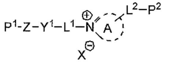
式(31)中、環Aは、含窒素複素環からなる第4級アンモニウムイオンを表す。Xは、アニオンを表す。L1は、2価の連結基を表す。L2は、単結合、又は、2価の連結基を表す。Y1は、5又は6員環を部分構造として有する2価の連結基を表す。Zは、2~20のアルキレン基を部分構造として有する2価の連結基を表す。P1及びP2は、それぞれ独立に、重合性エチレン性不飽和結合を有する一価の置換基を表す。
オニウム塩の具体例としては、特開2012-208397号公報の段落0052~0058号公報に記載のオニウム塩、特開2008-026730号公報の段落0024~0055に記載のオニウム塩、及び、特開2002-037777号公報に記載のオニウム塩が挙げられる。In formula (31), ring A represents a quaternary ammonium ion composed of a nitrogen-containing heterocycle. X represents an anion. L 1 represents a divalent linking group. L 2 represents a single bond or a divalent linking group. Y 1 represents a divalent linking group having a 5- or 6-membered ring as a partial structure. Z represents a divalent linking group having 2 to 20 alkylene groups as a partial structure. P 1 and P 2 each independently represent a monovalent substituent having a polymerizable ethylenically unsaturated bond.
Specific examples of the onium salt include the onium salt described in paragraphs 0052 to 0058 of JP2012-208397A, the onium salt described in paragraphs 0024 to 0055 of JP2008-026730, and the Japanese Patent Application Laid-Open No. 2012-026730. Examples thereof include the onium salt described in JP-A-2002-03777.
組成物中の垂直配向剤の含有量は、液晶性化合物全質量に対して、0.1~400質量%が好ましく、0.5~350質量%がより好ましい。
垂直配向剤は、単独で用いてもよいし、2種以上を組み合わせて用いてもよい。垂直配向剤が2種以上を用いられる場合、それらの合計量が上記範囲であることが好ましい。The content of the vertical alignment agent in the composition is preferably 0.1 to 400% by mass, more preferably 0.5 to 350% by mass, based on the total mass of the liquid crystal compound.
The vertical alignment agent may be used alone or in combination of two or more. When two or more kinds of vertical alignment agents are used, the total amount thereof is preferably in the above range.
組成物は、レベリング剤を含むことが好ましい。組成物がレベリング剤を含むと、異方性光吸収層の表面にかかる乾燥風による面状の荒れを抑制し、二色性物質がより均一に配向する。
レベリング剤は特に制限されず、フッ素原子を含むレベリング剤(フッ素系レベリング剤)、又は、ケイ素原子を含むレベリング剤(ケイ素系レベリング剤)が好ましく、フッ素系レベリング剤がより好ましい。The composition preferably contains a leveling agent. When the composition contains a leveling agent, the surface roughness due to the dry air applied to the surface of the anisotropic light absorption layer is suppressed, and the dichroic substance is more uniformly oriented.
The leveling agent is not particularly limited, and a leveling agent containing a fluorine atom (fluorine-based leveling agent) or a leveling agent containing a silicon atom (silicon-based leveling agent) is preferable, and a fluorine-based leveling agent is more preferable.
フッ素系レベリング剤としては、脂肪酸の一部がフルオロアルキル基で置換された多価カルボン酸の脂肪酸エステル類、及び、フルオロ置換基を有するポリアクリレート類が挙げられる。特に、二色性物質及び液晶性化合物として棒状化合物を用いる場合、二色性物質及び液晶性化合物の垂直配向を促進する点から、式(40)で表される化合物由来の繰り返し単位を含むレベリング剤が好ましい。 Examples of the fluorine-based leveling agent include fatty acid esters of polyvalent carboxylic acids in which a part of fatty acid is substituted with a fluoroalkyl group, and polyacrylates having a fluoro substituent. In particular, when a rod-shaped compound is used as the dichroic substance and the liquid crystal compound, leveling containing a repeating unit derived from the compound represented by the formula (40) from the viewpoint of promoting the vertical orientation of the dichroic substance and the liquid crystal compound. Agents are preferred.
式(40) Equation (40)

R0は、水素原子、ハロゲン原子、又は、メチル基を表す。
Lは、2価の連結基を表す。Lとしては、炭素数2~16のアルキレン基が好ましく、上記アルキレン基において隣接しない任意の-CH2-は、-O-、-COO-、-CO-、又は、-CONH-に置換されていてもよい。
nは、1~18の整数を表す。 R0 represents a hydrogen atom, a halogen atom, or a methyl group.
L represents a divalent linking group. As L, an alkylene group having 2 to 16 carbon atoms is preferable, and any -CH 2- not adjacent to the alkylene group is substituted with -O-, -COO-, -CO-, or -CONH-. May be.
n represents an integer from 1 to 18.
式(40)で表される化合物由来の繰り返し単位を有するレベリング剤は、さらに他の繰り返し単位を含んでいてもよい。
他の繰り返し単位としては、式(41)で表される化合物由来の繰り返し単位が挙げられる。The leveling agent having a repeating unit derived from the compound represented by the formula (40) may further contain another repeating unit.
Examples of the other repeating unit include a repeating unit derived from the compound represented by the formula (41).
式(41) Equation (41)

R11は、水素原子、ハロゲン原子、又は、メチル基を表す。
Xは、酸素原子、硫黄原子、又は、-N(R13)-を表す。R13は、水素原子、又は、炭素数1~8のアルキル基を表す。
R12は、水素原子、置換基を有してもよいアルキル基、又は、置換基を有していてもよい芳香族基を表す。上記アルキル基の炭素数は、1~20が好ましい。上記アルキル基は、直鎖状、分岐鎖状、及び、環状のいずれであってもよい。
また、上記アルキル基の有していてもよい置換基としては、ポリ(アルキレンオキシ)基、及び、重合性基が挙げられる。重合性基の定義は、上述した通りである。R 11 represents a hydrogen atom, a halogen atom, or a methyl group.
X represents an oxygen atom, a sulfur atom, or -N (R 13 )-. R 13 represents a hydrogen atom or an alkyl group having 1 to 8 carbon atoms.
R 12 represents a hydrogen atom, an alkyl group which may have a substituent, or an aromatic group which may have a substituent. The alkyl group preferably has 1 to 20 carbon atoms. The alkyl group may be linear, branched, or cyclic.
Examples of the substituent that the alkyl group may have include a poly (alkyleneoxy) group and a polymerizable group. The definition of the polymerizable group is as described above.
レベリング剤が、式(40)で表される化合物由来の繰り返し単位、及び、式(41)で表される化合物由来の繰り返し単位を含む場合、式(40)で表される化合物由来の繰り返し単位の含有量は、レベリング剤が含む全繰り返し単位に対して、10~90モル%が好ましく、15~95モル%がより好ましい。
レベリング剤が、式(40)で表される化合物由来の繰り返し単位、及び、式(41)で表される化合物由来の繰り返し単位を含む場合、式(41)で表される化合物由来の繰り返し単位の含有量は、レベリング剤が含む全繰り返し単位に対して、10~90モル%が好ましく、5~85モル%がより好ましい。When the leveling agent contains a repeating unit derived from the compound represented by the formula (40) and a repeating unit derived from the compound represented by the formula (41), the repeating unit derived from the compound represented by the formula (40). The content of is preferably 10 to 90 mol%, more preferably 15 to 95 mol%, based on all the repeating units contained in the leveling agent.
When the leveling agent contains a repeating unit derived from the compound represented by the formula (40) and a repeating unit derived from the compound represented by the formula (41), the repeating unit derived from the compound represented by the formula (41). The content of is preferably 10 to 90 mol%, more preferably 5 to 85 mol%, based on all the repeating units contained in the leveling agent.
また、レベリング剤としては、上述した式(40)で表される化合物由来の繰り返し単位に代えて、式(42)で表される化合物由来の繰り返し単位を含むレベリング剤も挙げられる。 Further, as the leveling agent, a leveling agent containing a repeating unit derived from a compound represented by the formula (42) instead of the repeating unit derived from the compound represented by the above-mentioned formula (40) can also be mentioned.
式(42) Equation (42)

R2は、水素原子、ハロゲン原子、又は、メチル基を表す。
L2は、2価の連結基を表す。
nは、1~18の整数を表す。R 2 represents a hydrogen atom, a halogen atom, or a methyl group.
L 2 represents a divalent linking group.
n represents an integer from 1 to 18.
レベリング剤の具体例としては、特開2004-331812号公報の段落0046~0052に例示される化合物、及び、特開2008-257205号公報の段落0038~0052に記載の化合物が挙げられる。 Specific examples of the leveling agent include the compounds exemplified in paragraphs 0046 to 0052 of JP-A-2004-331812 and the compounds described in paragraphs 0038-0052 of JP-A-2008-257205.
組成物中のレベリング剤の含有量は、液晶性化合物全質量に対して、10~80質量%が好ましく、20~60質量%がより好ましい。
レベリング剤は、単独で用いてもよいし、2種以上を組み合わせて用いてもよい。レベリング剤が2種以上を用いられる場合、それらの合計量が上記範囲であることが好ましい。The content of the leveling agent in the composition is preferably 10 to 80% by mass, more preferably 20 to 60% by mass, based on the total mass of the liquid crystal compound.
The leveling agent may be used alone or in combination of two or more. When two or more leveling agents are used, the total amount thereof is preferably in the above range.
組成物は、重合開始剤を含んでいてもよい。
重合開始剤の種類は特に制限されず、光重合開始剤、及び、熱重合開始剤が挙げられ、光重合開始剤が好ましい。なお、重合開始剤は、ラジカル重合開始剤、及び、カチオン重合開始剤のいずれであってもよい。
重合開始剤としては、異方性光吸収層の耐久性がより優れる点で、オキシムエステル化合物、及び、アシルホスフィン化合物からなる群から選択される少なくとも1種以上であることが好ましい。
組成物が重合開始剤を含む場合、重合開始剤の含有量は、組成物中の上記二色性物質と上記液晶性化合物との合計100質量部に対し、0.01~30質量部が好ましく、0.1~15質量部がより好ましい。
重合開始剤は、単独で用いてもよいし、2種以上を組み合わせて用いてもよい。重合開始剤が2種以上を用いられる場合、それらの合計量が上記範囲であることが好ましい。The composition may contain a polymerization initiator.
The type of the polymerization initiator is not particularly limited, and examples thereof include a photopolymerization initiator and a thermal polymerization initiator, and a photopolymerization initiator is preferable. The polymerization initiator may be either a radical polymerization initiator or a cationic polymerization initiator.
The polymerization initiator is preferably at least one selected from the group consisting of an oxime ester compound and an acylphosphine compound in that the durability of the anisotropic light absorbing layer is more excellent.
When the composition contains a polymerization initiator, the content of the polymerization initiator is preferably 0.01 to 30 parts by mass with respect to 100 parts by mass in total of the dichroic substance and the liquid crystal compound in the composition. , 0.1 to 15 parts by mass is more preferable.
The polymerization initiator may be used alone or in combination of two or more. When two or more kinds of polymerization initiators are used, the total amount thereof is preferably in the above range.
組成物は、作業性の点から、溶媒を含むことが好ましい。
溶媒としては、例えば、ケトン類、エーテル類、脂肪族炭化水素類(例えば、ヘキサン)、脂環式炭化水素類、芳香族炭化水素類、ハロゲン化炭素類、エステル類、アルコール類、セロソルブ類、セロソルブアセテート類、スルホキシド類、アミド類、及び、ヘテロ環化合物の有機溶媒、並びに、水が挙げられる。
組成物が溶媒を含む場合、溶媒の含有量は、液晶性組成物の全質量に対して、80~99質量%が好ましく、83~97質量%がより好ましい。
溶媒は、単独で用いてもよいし、2種以上を組み合わせて用いてもよい。溶媒が2種以上を用いられる場合、それらの合計量が上記範囲であることが好ましい。The composition preferably contains a solvent from the viewpoint of workability.
Examples of the solvent include ketones, ethers, aliphatic hydrocarbons (for example, hexane), alicyclic hydrocarbons, aromatic hydrocarbons, carbon halides, esters, alcohols, cellosolves, and the like. Examples thereof include cellosolve acetates, sulfoxides, amides, organic solvents for heterocyclic compounds, and water.
When the composition contains a solvent, the content of the solvent is preferably 80 to 99% by mass, more preferably 83 to 97% by mass, based on the total mass of the liquid crystal composition.
The solvent may be used alone or in combination of two or more. When two or more kinds of solvents are used, the total amount thereof is preferably in the above range.
上述した組成物を用いた異方性光吸収層の形成方法は特に制限されず、所定の基材上に上記組成物を塗布して塗膜を形成する工程(以下、「塗膜形成工程」ともいう。)と、塗膜に含まれる液晶性成分を配向させる工程(以下、「配向工程」ともいう。)と、塗膜に硬化処理を施す工程(以下、「硬化工程」ともいう。)をこの順に含む方法が挙げられる。
なお、液晶性成分とは、上述した液晶性化合物だけでなく、上述した二色性物質が液晶性を有している場合は、液晶性を有する二色性物質も含む成分である。
以下、上記各工程について詳述する。The method for forming the anisotropic light absorbing layer using the above-mentioned composition is not particularly limited, and is also referred to as a step of applying the above composition on a predetermined substrate to form a coating film (hereinafter, also referred to as a “coating film forming step”). ), The step of aligning the liquid crystal component contained in the coating film (hereinafter, also referred to as “alignment step”), and the step of applying a curing treatment to the coating film (hereinafter, also referred to as “curing step”). The method of including in order is mentioned.
The liquid crystal component is a component that includes not only the liquid crystal compound described above but also the dichroic substance having a liquid crystal property when the dichroic substance described above has a liquid crystal property.
Hereinafter, each of the above steps will be described in detail.
塗膜形成工程は、所定の基材上に組成物を塗布して塗膜を形成する工程である。
基材の種類は特に制限されず、透明支持体、及び、透明支持体上に配置された配向膜を有する積層体が挙げられる。
透明支持体を形成する材料としては、例えば、ポリカーボネート系ポリマー;ポリエチレンテレフタレート(PET)、及び、ポリエチレンナフタレート等のポリエステル系ポリマー;ポリメチルメタクリレート等のアクリル系ポリマー;ポリスチレン、及び、アクリロニトリル-スチレン共重合体(AS樹脂)等のスチレン系ポリマー;ポリエチレン、ポリプロピレン、及び、エチレン-プロピレン共重合体等のポリオレフィン系ポリマー;塩化ビニル系ポリマー;ナイロン、及び、芳香族ポリアミド等のアミド系ポリマー;イミド系ポリマー;スルホン系ポリマー;ポリエーテルスルホン系ポリマー;ポリエーテルエーテルケトン系ポリマー;ポリフェニレンスルフィド系ポリマー;塩化ビニリデン系ポリマー;ビニルアルコール系ポリマー;ビニルブチラール系ポリマー;アリレート系ポリマー;ポリオキシメチレン系ポリマー;エポキシ系ポリマー;等が挙げられる。
また、透明支持体を形成する材料としては、熱可塑性ノルボルネン系樹脂も好ましい。熱可塑性ノルボルネン系樹脂としては、日本ゼオン(株)製のゼオネックス及びゼオノア、並びに、JSR(株)製のアートンが挙げられる。
また、透明支持体を形成する材料としては、トリアセチルセルロース(TAC)に代表される、セルロース系ポリマーも好ましい。
透明支持体の厚みは特に制限されず、100μm以下が好ましく、80μm以下がより好ましく、10~80μmがさらに好ましい。
なお、本明細書において、「透明」とは、可視光の透過率が60%以上であることを示し、80%以上が好ましく、90%以上がより好ましい。The coating film forming step is a step of applying a composition on a predetermined substrate to form a coating film.
The type of the base material is not particularly limited, and examples thereof include a transparent support and a laminated body having an alignment film arranged on the transparent support.
Examples of the material for forming the transparent support include a polycarbonate polymer; a polyester polymer such as polyethylene terephthalate (PET) and polyethylene naphthalate; an acrylic polymer such as polymethylmethacrylate; and polystyrene and acrylonitrile-styrene. Sterite-based polymers such as polymers (AS resins); polyolefin-based polymers such as polyethylene, polypropylene, and ethylene-propylene copolymers; vinyl chloride-based polymers; nylon and amide-based polymers such as aromatic polyamides; imide-based Polymers; Symphonic polymers; Polyether sulfone polymers; Polyether ether ketone polymers; Polyphenylene sulfide polymers; Vinylidene chloride polymers; Vinyl alcohol polymers; Vinyl butyral polymers; Arilate polymers; Polyoxymethylene polymers; Epoxy System polymers; and the like.
Further, as a material for forming the transparent support, a thermoplastic norbornene-based resin is also preferable. Examples of the thermoplastic norbornene-based resin include Zeonex and Zeonoa manufactured by Zeon Corporation, and Arton manufactured by JSR Corporation.
Further, as a material for forming the transparent support, a cellulosic polymer typified by triacetyl cellulose (TAC) is also preferable.
The thickness of the transparent support is not particularly limited, and is preferably 100 μm or less, more preferably 80 μm or less, still more preferably 10 to 80 μm.
In the present specification, "transparent" means that the transmittance of visible light is 60% or more, preferably 80% or more, and more preferably 90% or more.
配向膜は、一般的には、ポリマーを主成分とする。配向膜用ポリマーとしては、多数の文献に記載があり、多数の市販品を入手することができる。利用されるポリマーは、ポリビニルアルコール(PVA)、ポリイミド、又は、その誘導体が好ましい。
なお、配向膜としては、公知のラビング処理が施された膜が好ましい。
また、配向膜としては、光配向膜を用いてもよい。光配向膜は、光配向化合物に対して直線偏光又は非偏光照射を施すことにより製造できる。光配向化合物としては、光の作用により二量化及び異性化の少なくとも一方が生じる光反応性基を有する感光性化合物が好ましい。また、光反応性基が、桂皮酸誘導体、クマリン誘導体、カルコン誘導体、マレイミド誘導体、アゾベンゼン化合物、ポリイミド化合物、スチルベン化合物、及び、スピロピラン化合物からなる群から選択される少なくとも1種の誘導体、又は、化合物の骨格を有することが好ましい。
配向膜の厚みは、0.01~10μmが好ましい。The alignment film is generally composed of a polymer as a main component. The polymer for an alignment film has been described in a large number of documents, and a large number of commercially available products are available. The polymer used is preferably polyvinyl alcohol (PVA), polyimide, or a derivative thereof.
As the alignment film, a known rubbing-treated film is preferable.
Further, as the alignment film, a photoalignment film may be used. The photo-alignment film can be produced by subjecting the photo-alignment compound to linearly polarized light or non-polarized irradiation. As the photoalignment compound, a photosensitive compound having a photoreactive group in which at least one of dimerization and isomerization is generated by the action of light is preferable. Further, the photoreactive group is at least one derivative or compound selected from the group consisting of a cinnamon acid derivative, a coumarin derivative, a chalcone derivative, a maleimide derivative, an azobenzene compound, a polyimide compound, a stilbene compound, and a spiropyran compound. It is preferable to have a stilbene.
The thickness of the alignment film is preferably 0.01 to 10 μm.
なお、上記では、基材として、透明支持体及び配向膜を含む積層体について述べたが、特にこの形態に制限されず、例えば、表面にラビング処理が施された透明支持体を用いてもよい。 In the above description, the laminated body including the transparent support and the alignment film has been described as the base material, but the present invention is not particularly limited to this form, and for example, a transparent support having a rubbing treatment on the surface may be used. ..
組成物の塗布方法としては、ロールコーティング法、グラビア印刷法、スピンコート法、ワイヤーバーコーティング法、押し出しコーティング法、ダイレクトグラビアコーティング法、リバースグラビアコーティング法、ダイコーティング法、スプレー法、及び、インクジェット法が挙げられる。 The composition can be applied by a roll coating method, a gravure printing method, a spin coating method, a wire bar coating method, an extrusion coating method, a direct gravure coating method, a reverse gravure coating method, a die coating method, a spray method, and an inkjet method. Can be mentioned.
配向工程は、塗膜に含まれる液晶性成分を配向させる工程である。
配向工程は、乾燥処理を有していてもよい。乾燥処理によって、溶媒等の成分を塗膜から除去できる。乾燥処理は、塗膜を室温下において所定時間放置する方法(例えば、自然乾燥)によって行われてもよいし、加熱及び/又は送風する方法によって行われてもよい。
ここで、液晶性組成物に含まれる液晶性成分は、上述した塗膜形成工程又は乾燥処理によって、配向する場合がある。
乾燥処理が塗膜に含まれる液晶性成分の液晶相への転移温度以上の温度により行われる場合には、後述する加熱処理は実施しなくてもよい。
塗膜に含まれる液晶性成分の液晶相への転移温度は、製造適性等の点から、10~250℃が好ましく、25~190℃がより好ましい。The alignment step is a step of aligning the liquid crystal component contained in the coating film.
The alignment step may have a drying process. By the drying treatment, components such as a solvent can be removed from the coating film. The drying treatment may be carried out by a method of leaving the coating film at room temperature for a predetermined time (for example, natural drying), or by a method of heating and / or blowing air.
Here, the liquid crystal component contained in the liquid crystal composition may be oriented by the above-mentioned coating film forming step or drying treatment.
When the drying treatment is performed at a temperature equal to or higher than the transition temperature of the liquid crystal component contained in the coating film to the liquid crystal phase, the heat treatment described later may not be performed.
The transition temperature of the liquid crystal component contained in the coating film to the liquid crystal phase is preferably 10 to 250 ° C, more preferably 25 to 190 ° C from the viewpoint of manufacturing suitability and the like.
配向工程は、加熱処理を有することが好ましい。これにより、塗膜に含まれる液晶性成分を配向させることができる。
加熱処理の際の加熱温度は、製造適性等の点から、10~250℃が好ましく、25~190℃がより好ましい。また、加熱時間は、1~300秒間が好ましく、1~90秒間がより好ましい。The orientation step preferably has a heat treatment. This makes it possible to orient the liquid crystal component contained in the coating film.
The heating temperature during the heat treatment is preferably 10 to 250 ° C., more preferably 25 to 190 ° C. from the viewpoint of manufacturing suitability and the like. The heating time is preferably 1 to 300 seconds, more preferably 1 to 90 seconds.
配向工程は、加熱処理後に実施される冷却処理を有していてもよい。冷却処理は、加熱後の塗膜を室温(20~25℃)程度まで冷却する処理である。これにより、塗膜に含まれる液晶性成分の配向を固定できる。冷却手段としては、特に制限されず、公知の方法により実施できる。 The alignment step may have a cooling treatment performed after the heat treatment. The cooling treatment is a treatment for cooling the heated coating film to about room temperature (20 to 25 ° C.). This makes it possible to fix the orientation of the liquid crystal component contained in the coating film. The cooling means is not particularly limited, and can be carried out by a known method.
硬化工程は、例えば、加熱及び/又は光照射(露光)によって実施される。このなかでも、硬化工程は光照射によって実施されることが好ましい。
硬化に用いる光は、赤外線、可視光、及び、紫外線が挙げられ、紫外線が好ましい。なお、硬化時に加熱しながら紫外線を照射してもよいし、特定の波長のみを透過するフィルターを介して紫外線を照射してもよい。
光照射を行う際の露光量は特に制限されないが、10~2000mJ/cm2が好ましく、異方性光吸収層の耐久性がより優れる点で、200~1000mJ/cm2がより好ましい。
露光が加熱しながら行われる場合、露光時の加熱温度は、25~140℃が好ましい。
また、露光は、窒素雰囲気下で行われてもよい。The curing step is carried out, for example, by heating and / or light irradiation (exposure). Among these, it is preferable that the curing step is carried out by light irradiation.
Examples of the light used for curing include infrared light, visible light, and ultraviolet light, and ultraviolet light is preferable. It should be noted that the ultraviolet rays may be irradiated while being heated at the time of curing, or the ultraviolet rays may be irradiated through a filter that transmits only a specific wavelength.
The exposure amount at the time of light irradiation is not particularly limited, but 10 to 2000 mJ / cm 2 is preferable, and 200 to 1000 mJ / cm 2 is more preferable in that the durability of the anisotropic light absorbing layer is more excellent.
When the exposure is carried out while heating, the heating temperature at the time of exposure is preferably 25 to 140 ° C.
Further, the exposure may be performed in a nitrogen atmosphere.
本発明の表示装置の第1実施形態の製造方法は特に制限されず、上述した自発光型表示素子と異方性光吸収層とを積層する方法が挙げられる。
両者を積層する際には、自発光型表示素子と異方性光吸収層との間に貼合層を配置して、両者を貼り合わせてもよい。
貼合層は、自発光型表示素子と異方性光吸収層と貼り合わせられる物であれば、公知の各種の材料からなるものが利用可能である。例えば、貼り合わせる際には流動性を有し、その後、固体になる、接着剤からなる層(接着剤層)でも、貼り合わせる際にゲル状(ゴム状)の柔らかい固体で、その後もゲル状の状態が変化しない、粘着剤からなる層(粘着剤層)でも、接着剤と粘着剤との両方の特徴を持った材料からなる層でもよい。貼合層の具体例としては、光学透明接着剤、光学透明両面テープ、及び、紫外線硬化型樹脂が挙げられる。
なお、貼合層で貼り合わせるのではなく、自発光型表示素子と異方性光吸収層とを積層して、枠体又は治具等で保持して、本発明の表示装置を構成してもよい。The manufacturing method of the first embodiment of the display device of the present invention is not particularly limited, and examples thereof include a method of laminating the above-mentioned self-luminous display element and an anisotropic light absorbing layer.
When laminating both, a laminating layer may be arranged between the self-luminous display element and the anisotropic light absorbing layer, and the two may be laminated.
As the bonding layer, a material made of various known materials can be used as long as it can be bonded to the self-luminous display element and the anisotropic light absorbing layer. For example, a layer made of an adhesive (adhesive layer), which has fluidity when bonded and then becomes a solid, is a soft solid gel-like (rubber-like) when bonded, and then gel-like. It may be a layer made of an adhesive (adhesive layer) in which the state of the above does not change, or a layer made of a material having the characteristics of both an adhesive and an adhesive. Specific examples of the bonded layer include an optical transparent adhesive, an optical transparent double-sided tape, and an ultraviolet curable resin.
In addition, instead of laminating with a laminating layer, a self-luminous display element and an anisotropic light absorbing layer may be laminated and held by a frame or a jig to form the display device of the present invention. ..
本発明の表示装置の第2実施形態は、表示素子、及び、異方性光吸収層以外の部材を含んでいてもよい。例えば、上述した、貼合層、及び、基材等が挙げられる。 The second embodiment of the display device of the present invention may include a display element and a member other than the anisotropic light absorbing layer. For example, the above-mentioned laminated layer, a base material, and the like can be mentioned.
<<第2実施形態>>
図3に、本発明の表示装置の第2実施形態の模式的な断面図を示す。
図3に示すように、表示装置10Bは、自発光型表示素子12と、異方性光吸収層14、λ/4板16と、偏光子18とを含む。なお、図3において、観察者は偏光子18側から観察する。従って、表示装置10Bは、視認側から、偏光子18と、λ/4板16と、異方性光吸収層14と、自発光型表示素子12とをこの順で含む。
表示装置10Bは、λ/4板16及び偏光子18をさらに含む点以外は、上述した表示装置10Aと同様の構成を有する。
以下では、主に、λ/4板16及び偏光子18について詳述する。<< Second Embodiment >>
FIG. 3 shows a schematic cross-sectional view of the second embodiment of the display device of the present invention.
As shown in FIG. 3, the
The
In the following, the λ / 4
<λ/4板>
λ/4板とは、λ/4機能を有する板であり、具体的には、ある特定の波長の直線偏光を円偏光に(又は円偏光を直線偏光に)変換する機能を有する板である。
λ/4板の具体例としては、例えば、米国特許出願公開2015/0277006号等に記載のλ/4板が挙げられる。
なお、λ/4板が単層構造である態様としては、具体的には、延伸ポリマーフィルム、及び、液晶性化合物を用いて形成された光学異方性層が挙げられる。
また、λ/4板が複層構造である態様としては、具体的には、λ/4板とλ/2板とを積層してなる広帯域λ/4板が挙げられる。<λ / 4 plate>
The λ / 4 plate is a plate having a λ / 4 function, and specifically, a plate having a function of converting linear polarization of a specific wavelength into circular polarization (or circular polarization into linear polarization). ..
Specific examples of the λ / 4 plate include the λ / 4 plate described in US Patent Application Publication No. 2015/0277006.
Specific examples of the embodiment in which the λ / 4 plate has a single-layer structure include a stretched polymer film and an optically anisotropic layer formed by using a liquid crystal compound.
Further, as an embodiment in which the λ / 4 plate has a multi-layer structure, specifically, a wide band λ / 4 plate formed by laminating a λ / 4 plate and a λ / 2 plate can be mentioned.
λ/4板のRe(550)は特に制限されないが、λ/4板として有用である点で、110~160nmが好ましく、120~150nmがより好ましい。 The Re (550) of the λ / 4 plate is not particularly limited, but 110 to 160 nm is preferable, and 120 to 150 nm is more preferable, in that it is useful as a λ / 4 plate.
λ/4板は、逆波長分散性を示すのが好ましい。λ/4板が逆波長分散性を示すとは、特定波長(可視光範囲)における面内のレタデーション(Re)値を測定した際に、測定波長が大きくなるにつれてRe値が同等又は高くなるものをいう。 The λ / 4 plate preferably exhibits reverse wavelength dispersibility. The fact that the λ / 4 plate exhibits reverse wavelength dispersibility means that when the in-plane retardation (Re) value at a specific wavelength (visible light range) is measured, the Re value becomes equal or higher as the measurement wavelength increases. To say.
<偏光子>
偏光子は、光を特定の直線偏光に変換する機能を有する部材(直線偏光子)であればよく、主に、吸収型偏光子を利用できる。
吸収型偏光子としては、ヨウ素系偏光子、二色性物質を利用したニ色性物質系偏光子、及び、ポリエン系偏光子が挙げられる。ヨウ素系偏光子及びニ色性物質系偏光子には、塗布型偏光子と延伸型偏光子とがあり、いずれも適用できるが、ポリビニルアルコールにヨウ素又は二色性物質を吸着させ、延伸して作製される偏光子が好ましい。
偏光子の吸収軸とλ/4板の遅相軸との関係は特に制限されないが、偏光子とλ/4板との積層物が円偏光板として好適に作用する点から、偏光子の吸収軸とλ/4板の遅相軸とのなす角は、45°±10°が好ましい。<Polarizer>
The splitter may be any member (linear deflector) having a function of converting light into specific linear polarization, and an absorption type polarizing element can be mainly used.
Examples of the absorption type polarizing element include an iodine-based polarizing element, a dichroic substance-based polarizing element using a dichroic substance, and a polyene-based polarizing element. The iodine-based polarizing element and the dichroic material-based polarizing element include a coating type polarizing element and a stretching type polarizing element, both of which can be applied. However, iodine or a dichroic substance is adsorbed on polyvinyl alcohol and stretched. The polarizing element produced is preferable.
The relationship between the absorber's absorption axis and the slow axis of the λ / 4 plate is not particularly limited, but the absorber's absorption is such that the laminate of the substituent and the λ / 4 plate acts as a circular polarizing plate. The angle formed by the axis and the slow axis of the λ / 4 plate is preferably 45 ° ± 10 °.
本発明の表示装置の第2実施形態においては、λ/4板及び偏光子をさらに含む。この2つの部材は、いわゆる円偏光板として機能できる。つまり、λ/4板及び偏光子を含む円偏光板を表示素子上に配置することにより、表示装置に反射防止機能を付与できる。 In the second embodiment of the display device of the present invention, a λ / 4 plate and a splitter are further included. These two members can function as a so-called circular polarizing plate. That is, the antireflection function can be imparted to the display device by arranging the λ / 4 plate and the circular polarizing plate including the polarizing element on the display element.
本発明の表示装置の第2実施形態の製造方法は、上述した第1実施形態で説明した方法が挙げられる。
また、本発明の表示装置の第2実施形態は、自発光型表示素子、異方性光吸収層、λ/4板、及び、偏光子以外の部材を含んでいてもよい。例えば、上述した、貼合層、及び、基材等が挙げられる。Examples of the manufacturing method of the second embodiment of the display device of the present invention include the methods described in the first embodiment described above.
In addition, the second embodiment of the display device of the present invention may include a self-luminous display element, an anisotropic light absorption layer, a λ / 4 plate, and a member other than the polarizing element. For example, the above-mentioned laminated layer, a base material, and the like can be mentioned.
<<第3実施形態>>
図4に、本発明の表示装置の第3実施形態の模式的な断面図を示す。
図4に示すように、表示装置10Cは、自発光型表示素子12と、λ/4板16と、異方性光吸収層14、偏光子18とを含む。なお、図4において、観察者は偏光子18側から観察する。従って、表示装置10Bは、視認側から、偏光子18と、異方性光吸収層14と、λ/4板16と、自発光型表示素子12とをこの順で含む。
表示装置10Cは、異方性光吸収層14及びλ/4板16の積層順以外は、表示装置10Bと同じ構成を有する。
表示装置10Cにおいては、異方性光吸収層14が、偏光子18とλ/4板16との間に配置されるが、偏光子18とλ/4板16とで達成される円偏光板の機能は表示装置10Cに付与される。<< Third Embodiment >>
FIG. 4 shows a schematic cross-sectional view of a third embodiment of the display device of the present invention.
As shown in FIG. 4, the
The
In the
本発明の表示装置の第3実施形態の製造方法は、上述した第1実施形態で説明した方法が挙げられる。
また、本発明の表示装置の第3実施形態は、自発光型表示素子、異方性光吸収層、λ/4板、及び、偏光子以外の部材を含んでいてもよい。例えば、上述した、貼合層、及び、基材等が挙げられる。Examples of the manufacturing method of the third embodiment of the display device of the present invention include the methods described in the first embodiment described above.
Further, the third embodiment of the display device of the present invention may include a self-luminous display element, an anisotropic light absorption layer, a λ / 4 plate, and a member other than the polarizing element. For example, the above-mentioned laminated layer, a base material, and the like can be mentioned.
以下に、実施例を挙げて本発明をさらに具体的に説明する。以下の実施例に示す材料、試薬、物質量及びその割合、並びに、操作等は本発明の趣旨から逸脱しない限り適宜変更できる。従って、本発明の範囲は以下の具体例に制限されない。 Hereinafter, the present invention will be described in more detail with reference to examples. The materials, reagents, amounts of substances and their ratios, operations and the like shown in the following examples can be appropriately changed as long as they do not deviate from the gist of the present invention. Therefore, the scope of the present invention is not limited to the following specific examples.
<実施例1>
(配向膜の形成)
セルロースアセテートフィルム(富士フイルム製、フジタックTG40)を温度60℃の誘電式加熱ロールを通過させ、フィルム表面温度を40℃に昇温した。その後、フィルムの片面に下記に示す組成のアルカリ溶液を、バーコーターを用いて塗布量14ml/m2で塗布し、110℃に加熱し、(株)ノリタケカンパニーリミテド製のスチーム式遠赤外ヒーターの下に、得られたフィルムを10秒間搬送した。次に、得られたフィルムに対して、バーコーターを用いて純水を3ml/m2塗布した。次に、得られたフィルムに対して、ファウンテンコーターによる水洗とエアナイフによる水切りとを3回繰り返した後に、フィルムを70℃の乾燥ゾーンに10秒間搬送して乾燥し、アルカリ鹸化処理したセルロースアセテートフィルムを作製した。
─────────────────────────────────
アルカリ溶液
─────────────────────────────────
水酸化カリウム 4.7質量部
水 15.8質量部
イソプロパノール 63.7質量部
界面活性剤(C14H29O(CH2CH2O)20H) 1.0質量部
プロピレングリコール 14.8質量部
─────────────────────────────────<Example 1>
(Formation of alignment film)
A cellulose acetate film (manufactured by Fujifilm, Fujitac TG40) was passed through a dielectric heating roll having a temperature of 60 ° C., and the film surface temperature was raised to 40 ° C. Then, an alkaline solution having the composition shown below is applied to one side of the film at a coating amount of 14 ml / m 2 using a bar coater, heated to 110 ° C., and a steam far-infrared heater manufactured by Noritake Co., Ltd. Limited. The resulting film was conveyed underneath for 10 seconds. Next, 3 ml / m 2 of pure water was applied to the obtained film using a bar coater. Next, the obtained film was washed with water by a fountain coater and drained with an air knife three times, and then the film was transported to a drying zone at 70 ° C. for 10 seconds to be dried and subjected to alkali saponification treatment. Was produced.
────────────────────────────────
Alkaline solution ────────────────────────────────
Potassium hydroxide 4.7 parts by mass Water 15.8 parts by mass Isopropanol 63.7 parts by mass Surfactant (C 14 H 29 O (CH 2 CH 2 O) 20 H) 1.0 parts by mass Propylene glycol 14.8 parts by mass Department ────────────────────────────────
アルカリ鹸化処理したセルロースアセテートフィルム上に、下記の配向膜形成用組成物1を#12のバーを用いて塗布し、得られたフィルムを110℃にて2分間乾燥し、配向膜1を形成した。
─────────────────────────────────
配向膜形成用組成物1
─────────────────────────────────
下記変性ポリビニルアルコール 2.00質量部
水 74.08質量部
メタノール 23.76質量部
光重合開始剤(イルガキュア2959、BASF社製) 0.06質量部
─────────────────────────────────The following composition 1 for forming an alignment film was applied onto an alkali-saponified cellulose acetate film using a bar of # 12, and the obtained film was dried at 110 ° C. for 2 minutes to form an alignment film 1. ..
────────────────────────────────
Composition for forming an alignment film 1
────────────────────────────────
The following modified polyvinyl alcohol 2.00 parts by mass water 74.08 parts by mass methanol 23.76 parts by mass Photopolymerization initiator (Irgacure 2959, manufactured by BASF) 0.06 parts by mass ──────────── ─────────────────────
変性ポリビニルアルコール(下記式で表される化合物。式中、繰り返し単位に付された数値は、全繰り返し単位に対する、各繰り返し単位のモル比率を表す。) Modified polyvinyl alcohol (a compound represented by the following formula. In the formula, the numerical value attached to the repeating unit represents the molar ratio of each repeating unit to all the repeating units).

(異方性光吸収層の形成)
得られた配向膜1上に、バーコーターを用いて異方性光吸収層形成用組成物A1を塗布し、塗膜を形成した。塗膜を室温にて30秒間乾燥させた後、145℃まで加熱して20秒間保持し、塗膜を室温になるまで冷却した。次に、室温まで冷却した塗膜を紫外線照射(露光量:500mJ/cm2、超高圧水銀ランプ使用)によって配向を固定化し、異方性光吸収層を有するフィルム1を製造した。異方性光吸収層の膜厚は、1.5μmであった。(Formation of anisotropic light absorption layer)
The composition A1 for forming an anisotropic light absorbing layer was applied onto the obtained alignment film 1 using a bar coater to form a coating film. The coating film was dried at room temperature for 30 seconds, then heated to 145 ° C. and held for 20 seconds, and the coating film was cooled to room temperature. Next, the coating film cooled to room temperature was fixed in orientation by irradiation with ultraviolet rays (exposure amount: 500 mJ / cm 2 , using an ultrahigh pressure mercury lamp) to produce a film 1 having an anisotropic light absorbing layer. The film thickness of the anisotropic light absorbing layer was 1.5 μm.
――――――――――――――――――――――――――――――
異方性光吸収層形成用組成物A1
――――――――――――――――――――――――――――――
液晶性化合物P-1 16.7質量部
化合物B1 16.7質量部
化合物E1 28.5質量部
化合物E2 28.5質量部
重合開始剤(BASF製、イルガキュア819) 0.15質量部
レベリング剤L1 6.95質量部
レベリング剤L2 2.49質量部
テトラヒドロフラン 11012質量部
シクロペンタノン 1943質量部
――――――――――――――――――――――――――――――――――――――――――――――――――――――――――――
Composition for forming an anisotropic light absorbing layer A1
――――――――――――――――――――――――――――――
Liquid liquid compound P-1 16.7 parts by mass Compound B1 16.7 parts by mass Compound E1 28.5 parts by mass Compound E2 28.5 parts by mass Polymerization initiator (BASF, Irgacure 819) 0.15 parts by mass Leveling agent L1 6.95 parts by mass Leveling agent L2 2.49 parts by mass tetrahydrofuran 11012 parts by mass Cyclopentanone 1943 parts by mass ――――――――――――――――――――――――――― ―――
液晶性化合物P-1(下記式で表される化合物。式中、繰り返し単位に付された数値は、全繰り返し単位に対する、各繰り返し単位のモル比率を表す。) Liquid crystalline compound P-1 (Compound represented by the following formula. In the formula, the numerical value attached to the repeating unit represents the molar ratio of each repeating unit to all the repeating units).

化合物B1(下記式で表される化合物) Compound B1 (compound represented by the following formula)

化合物E1(下記式で表される化合物) Compound E1 (compound represented by the following formula)

化合物E2(下記式で表される化合物) Compound E2 (compound represented by the following formula)

レベリング剤L1(下記式で表される化合物。式中、繰り返し単位に付された数値は、全繰り返し単位に対する、各繰り返し単位のモル比率を表す。) Leveling agent L1 (Compound represented by the following formula. In the formula, the numerical value attached to the repeating unit represents the molar ratio of each repeating unit to all the repeating units).

レベリング剤L2(下記式で表される化合物。式中、繰り返し単位に付された数値は、全繰り返し単位に対する、各繰り返し単位のモル比率を表す。) Leveling agent L2 (Compound represented by the following formula. In the formula, the numerical value attached to the repeating unit represents the molar ratio of each repeating unit to all the repeating units).

(垂直配向性評価)
得られた異方性光吸収層の膜厚方向をz軸としたときに、偏光顕微鏡のポラライザの振動方向とアナライザの振動方向とが直交したクロスニコル(直交ニコル)の状態において、異方性光吸収層をクロスニコルの間に設置してz軸方向から観察した際の透過光強度を官能評価した。
透過光強度は、z軸を回転軸として異方性光吸収層の方位角を360°回転させて評価した。光漏れがある場合、その方位軸に屈折率異方性があることを表し、光漏れがなければ、異方性光吸収層を構成している液晶性部位の配向が均一に垂直配向していることを表している。結果を表1に示す。
A: 全方位において透過光が全く観察できない(良好な垂直配向)
B: わずかに透過光が観察される方位がある(わずかに傾いた垂直配向)
C: 全方位でわずかに透過光が観察される(配向のわずかな乱れ)
D: 全方位で明らかな透過光が観察される。(配向の大きな乱れ)(Evaluation of vertical orientation)
When the film thickness direction of the obtained anisotropic light absorbing layer is taken as the z-axis, the anisotropic light absorbing layer is provided in a cross Nicol (orthogonal Nicol) state in which the vibration direction of the polarizer of the polarizing microscope and the vibration direction of the analyzer are orthogonal to each other. The transmitted light intensity when installed between the cross Nicols and observed from the z-axis direction was sensorimetrically evaluated.
The transmitted light intensity was evaluated by rotating the azimuth angle of the anisotropic light absorbing layer by 360 ° with the z-axis as the axis of rotation. If there is light leakage, it means that the azimuth axis has refractive index anisotropy, and if there is no light leakage, the orientation of the liquid crystal parts constituting the anisotropic light absorption layer is uniformly vertical. Represents. The results are shown in Table 1.
A: No transmitted light can be observed in all directions (good vertical orientation).
B: There is an orientation in which transmitted light is slightly observed (slightly tilted vertical orientation).
C: Slightly transmitted light is observed in all directions (slight distortion of orientation)
D: Clear transmitted light is observed in all directions. (Large disorder of orientation)
<実施例2>
異方性光吸収層形成用組成物A1において、化合物B1を下記化合物B2に代えた以外は、実施例1と同様の手順に従って、異方性光吸収層を有するフィルム2を作製した。垂直配向性評価の結果を表1に示す。<Example 2>
In the composition A1 for forming an anisotropic light absorbing layer, a film 2 having an anisotropic light absorbing layer was produced according to the same procedure as in Example 1 except that compound B1 was replaced with the following compound B2. The results of the vertical orientation evaluation are shown in Table 1.
化合物B2(下記式で表される化合物) Compound B2 (compound represented by the following formula)

<実施例3>
異方性光吸収層を有するフィルムの形成に際し、露光量を500mJ/cm2から100mJ/cm2とした以外は、実施例1と同様の手順に従って、異方性光吸収層を有するフィルム3を作製した。垂直配向性評価の結果を表1に示す。<Example 3>
When forming the film having the anisotropic light absorbing layer, the film 3 having the anisotropic light absorbing layer was produced according to the same procedure as in Example 1 except that the exposure amount was set to 500 mJ / cm 2 to 100 mJ / cm 2 . The results of the vertical orientation evaluation are shown in Table 1.
<実施例4>
異方性光吸収層形成用組成物A1において、光重合開始剤としてイルガキュア819の代わりにイルガキュア907(BASF製)を用いた以外は、実施例1と同様の手順に従って、異方性光吸収層を有するフィルム4を作製した。垂直配向性評価の結果を表1に示す。<Example 4>
A film 4 having an anisotropic light absorption layer according to the same procedure as in Example 1 except that Irgacure 907 (manufactured by BASF) was used instead of Irgacure 819 as the photopolymerization initiator in the composition A1 for forming an anisotropic light absorption layer. Was produced. The results of the vertical orientation evaluation are shown in Table 1.
<実施例5>
異方性光吸収層形成用組成物A1において、化合物B1を下記化合物B4に代えた以外は、実施例1と同様の手順に従って、異方性光吸収層を有するフィルム5を作製した。垂直配向性評価の結果を表1に示す。<Example 5>
In the composition A1 for forming an anisotropic light absorbing layer, a film 5 having an anisotropic light absorbing layer was produced according to the same procedure as in Example 1 except that compound B1 was replaced with the following compound B4. The results of the vertical orientation evaluation are shown in Table 1.
化合物B4(下記式で表される化合物)

<実施例6>
異方性光吸収層形成用組成物A1において、液晶性化合物P-1を液晶性化合物P-2に代えた以外は、実施例1と同様の手順に従って、異方性光吸収層を有するフィルム6を作製した。垂直配向性評価の結果を表1に示す。<Example 6>
In the composition A1 for forming an anisotropic light absorbing layer, a film 6 having an anisotropic light absorbing layer was produced according to the same procedure as in Example 1 except that the liquid crystal compound P-1 was replaced with the liquid crystal compound P-2. .. The results of the vertical orientation evaluation are shown in Table 1.
液晶性化合物P-2(下記式で表される化合物。式中、繰り返し単位に付された数値は、全繰り返し単位に対する、各繰り返し単位のモル比率を表す。) Liquid crystalline compound P-2 (Compound represented by the following formula. In the formula, the numerical value attached to the repeating unit represents the molar ratio of each repeating unit to all the repeating units).

<比較例1>
異方性光吸収層形成用組成物A1において、化合物B1を下記化合物B3に代えた以外は、実施例1と同様の手順に従って、異方性光吸収層を有するフィルム7を作製した。垂直配向性評価の結果を表1に示す。<Comparative Example 1>
In the composition A1 for forming an anisotropic light absorbing layer, a film 7 having an anisotropic light absorbing layer was produced according to the same procedure as in Example 1 except that compound B1 was replaced with the following compound B3. The results of the vertical orientation evaluation are shown in Table 1.
化合物B3(下記式で表される化合物)

<比較例2>
異方性光吸収層形成用組成物A1に代えて異方性光吸収層形成用組成物A2を用いた以外は、実施例1と同様の手順に従って、異方性光吸収層を有するフィルム8を作製した。垂直配向性評価の結果を表1に示す。<Comparative Example 2>
A film 8 having an anisotropic light absorbing layer was produced according to the same procedure as in Example 1 except that the composition A2 for forming an anisotropic light absorbing layer was used instead of the composition A1 for forming an anisotropic light absorbing layer. The results of the vertical orientation evaluation are shown in Table 1.
――――――――――――――――――――――――――――――
異方性光吸収層形成用組成物A2
――――――――――――――――――――――――――――――
液晶性化合物P-1 22.3質量部
化合物B1 11.1質量部
化合物E1 28.5質量部
化合物E2 28.5質量部
重合開始剤(BASF製、イルガキュア819) 0.15質量部
レベリング剤L1 7.0質量部
レベリング剤L2 2.5質量部
テトラヒドロフラン 11012質量部
シクロペンタノン 1943質量部
――――――――――――――――――――――――――――――――――――――――――――――――――――――――――――
Composition for forming an anisotropic light absorbing layer A2
――――――――――――――――――――――――――――――
Liquid liquid compound P-1 22.3 parts by mass Compound B1 11.1 parts by mass Compound E1 28.5 parts by mass Compound E2 28.5 parts by mass Polymerization initiator (BASF, Irgacure 819) 0.15 parts by mass Leveling agent L1 7.0 parts by mass Leveling agent L2 2.5 parts by mass tetrahydrofuran 11012 parts by mass Cyclopentanone 1943 parts by mass ――――――――――――――――――――――――――― ―――
<比較例3>
異方性光吸収層形成用組成物A1に代えて異方性光吸収層形成用組成物A3を用いた以外は、実施例1と同様の手順に従って、異方性光吸収層を有するフィルム9を作製した。垂直配向性評価の結果を表1に示す。<Comparative Example 3>
A film 9 having an anisotropic light absorbing layer was produced according to the same procedure as in Example 1 except that the composition A3 for forming an anisotropic light absorbing layer was used instead of the composition A1 for forming an anisotropic light absorbing layer. The results of the vertical orientation evaluation are shown in Table 1.
――――――――――――――――――――――――――――――
異方性光吸収層形成用組成物A3
――――――――――――――――――――――――――――――
液晶性化合物P-1 38.8質量部
化合物B1 38.8質量部
重合開始剤(BASF製、イルガキュア819) 0.36質量部
レベリング剤L1 16.2質量部
レベリング剤L2 5.8質量部
テトラヒドロフラン 11012質量部
シクロペンタノン 1943質量部
――――――――――――――――――――――――――――――――――――――――――――――――――――――――――――
Composition for forming an anisotropic light absorbing layer A3
――――――――――――――――――――――――――――――
Liquidity compound P-1 38.8 parts by mass Compound B1 38.8 parts by mass Polymerization initiator (BASF, Irgacure 819) 0.36 parts by mass Leveling agent L1 16.2 parts by mass Leveling agent L2 5.8 parts by mass tetrahydrofuran 11012 parts by mass Cyclopentanone 1943 parts by mass ――――――――――――――――――――――――――――――
<比較例4>
異方性光吸収層形成用組成物A1に代えて異方性光吸収層形成用組成物A4を用いた以外は、実施例1と同様の手順に従って、異方性光吸収層を有するフィルム10を作製した。垂直配向性評価の結果を表1に示す。<Comparative Example 4>
A film 10 having an anisotropic light absorbing layer was produced according to the same procedure as in Example 1 except that the composition A4 for forming an anisotropic light absorbing layer was used instead of the composition A1 for forming an anisotropic light absorbing layer. The results of the vertical orientation evaluation are shown in Table 1.
――――――――――――――――――――――――――――――
異方性光吸収層形成用組成物A4
――――――――――――――――――――――――――――――
液晶性化合物P-1 18.4質量部
化合物B1 18.4質量部
化合物E1 31.5質量部
化合物E2 31.5質量部
重合開始剤(BASF製、イルガキュア819) 0.17質量部
テトラヒドロフラン 11012質量部
シクロペンタノン 1943質量部
――――――――――――――――――――――――――――――――――――――――――――――――――――――――――――
Composition for forming an anisotropic light absorbing layer A4
――――――――――――――――――――――――――――――
Liquidity compound P-1 18.4 parts by mass Compound B1 18.4 parts by mass Compound E1 31.5 parts by mass Compound E2 31.5 parts by mass Polymerization initiator (BASF, Irgacure 819) 0.17 parts by mass tetrahydrofuran 11012 parts by mass Part Cyclopentanone 1943 Mass part ――――――――――――――――――――――――――――――
<評価>
(吸光度の異方性の測定)
作製した異方性光吸収層を有するフィルム1~10について、以下のようにして吸光度の異方性を測定した。
分光光度計(島津製作所株式会社製 UV-3150)を用いて、ダブルビーム法により2nmステップにて380~680nmの波長範囲で、極大吸収波長での3次元吸光度を測定した。ここでの3次元吸光度とは、異方性光吸収層の法線方向から極角60°の全方位角において、極大吸収波長での異方性光吸収層の吸光度を測定した際に、最も吸光度の高い値を示す方位角をx軸、異方性光吸収層の法線方向から極角60°の全方位角において、極大吸収波長での異方性光吸収層の吸光度を測定した際に、最も吸光度の低い値を示す方位角をy軸、異方性光吸収層の法線方向をz軸としたとき、入射する平行光に対する各々の方向の吸光度(Ax、Ay、Az)である。具体的には、測定光である直線偏光に対して、サンプルを回転させることで測定を行った。ここでAmax(60)=Ax(60)であり、Amin(60)=Ay(60)であり、A(0)=Azである。Amax(60)、Amin(60)、A(0)、Amax(60)/Amax(0)、および、Amax(60)/Amin(60)の値を表1に示す。<Evaluation>
(Measurement of absorbance anisotropy)
The anisotropy of the absorbance of the prepared films 1 to 10 having the anisotropic light absorbing layer was measured as follows.
Using a spectrophotometer (UV-3150 manufactured by Shimadzu Corporation), the three-dimensional absorbance at the maximum absorption wavelength was measured in the wavelength range of 380 to 680 nm in 2 nm steps by the double beam method. The three-dimensional absorbance here is the value having the highest absorbance when the absorbance of the anisotropic light-absorbing layer at the maximum absorption wavelength is measured at an omnidirectional angle of 60 ° from the normal direction of the anisotropic light-absorbing layer. When the absorbance of the anisotropic light-absorbing layer at the maximum absorption wavelength is measured at an azimuth angle of x-axis and an omnidirectional angle of 60 ° from the normal direction of the anisotropic light-absorbing layer, the value with the lowest absorbance is used. When the indicated azimuth angle is the y-axis and the normal direction of the anisotropic light absorbing layer is the z-axis, it is the absorbance (Ax, Ay, Az) in each direction with respect to the incident parallel light. Specifically, the measurement was performed by rotating the sample with respect to the linear polarization which is the measurement light. Here, Amax (60) = Ax (60), Amin (60) = Ay (60), and A (0) = Az. The values of Amax (60), Amin (60), A (0), Amax (60) / Amax (0), and Amax (60) / Amin (60) are shown in Table 1.
(重合性エチレン性不飽和結合量の定量)
異方性光吸収層を有するフィルム1~10における厚さ方向に対して垂直な2つの表面のうち、異方性光吸収層の配向膜側とは反対側の表面に粘接着剤層を貼合した後、粘接着剤層を介して異方性光吸収層を仮支持体フィルムに貼り合せて、セルロースアセテートフィルムを剥離して、積層体サンプルR1~10を作製した。
得られた積層体サンプルR1~10、及び、転写前の異方性光吸収層1~10に対して、Nicolet6700(サーモフィッシャーサイエンティフィック社製)にて赤外全反射吸収スペクトルの測定を行い、得られた測定結果(エチレン性不飽和結合の面内変角振動(1408cm-1)由来のピーク強度I(1)と、芳香族環の不飽和結合の伸縮振動(1504cm-1)由来のピーク強度I(2)の値)から、P1(配向膜とは反対側の表面の値)およびP2(配向膜と接していた側の面)を算出し、その比を求めた。結果を表1に示す。(Quantitative amount of polymerizable ethylenically unsaturated bond)
After the adhesive layer is bonded to the surface of the films 1 to 10 having the anisotropic light absorbing layer, which is perpendicular to the thickness direction, on the surface opposite to the alignment film side of the anisotropic light absorbing layer. The anisotropic light absorbing layer was attached to the temporary support film via the adhesive layer, and the cellulose acetate film was peeled off to prepare laminated samples R1 to 10.
Infrared total reflection absorption spectra were measured with Nicolet 6700 (manufactured by Thermo Fisher Scientific Co., Ltd.) for the obtained laminate samples R1 to 10 and the unsaturated light absorption layers 1 to 10 before transfer. Peak intensity I (1) derived from the measured results (in-plane variable angle vibration of ethylenically unsaturated bond (1408 cm -1 )) and peak intensity derived from expansion and contraction vibration of unsaturated bond of aromatic ring (1504 cm -1 ). From I (value)), P1 (the value of the surface opposite to the alignment film) and P2 (the surface on the side in contact with the alignment film) were calculated, and their ratios were calculated. The results are shown in Table 1.
(OLED(Organic Light Emitting Diode)パネルへの実装)
マイクロキャビティ構造を有するOLED表示素子として、Samsung製Galaxy Edge S8+からOLED表示素子を取り出し、その表示面に粘着剤を介して異方性光吸収層を有するフィルム1~10をそれぞれ貼合して、異方性光吸収層を有するOLED表示装置を作製した。得られたOLED表示装置を最大輝度白表示とし、正面方向を視認により評価した。結果を表1に示す。
A: ニュートラルな白である。
B: およそニュートラルな白である。
C: わずかに色味を帯びている。
D: 明確に色味を帯びている。
また、得られたOLED表示装置を最大輝度白表示とし、極角60°での全方位角にて視認した際に、最も評価が悪かった全方位角での評価結果を表1に示す。(Mounting on OLED (Organic Light Emitting Diode) panel)
As an OLED display element having a microcavity structure, an OLED display element is taken out from a Galaxy Edge S8 + manufactured by Samsung, and films 1 to 10 having an anisotropic light absorbing layer are bonded to the display surface via an adhesive, respectively, to obtain anisotropic light. An OLED display device having an absorption layer was manufactured. The obtained OLED display device was set to the maximum luminance white display, and the front direction was visually evaluated. The results are shown in Table 1.
A: Neutral white.
B: Approximately neutral white.
C: Slightly tinted.
D: It is clearly colored.
Further, Table 1 shows the evaluation results at the omnidirectional angle, which was the worst evaluation when the obtained OLED display device was set to the maximum brightness white display and visually recognized at the omnidirectional angle at the polar angle of 60 °.
(耐久性評価)
60℃、90%RHの条件下にて、得られたフィルム1~10を500時間湿熱処理した後、Amax(60)/A(0)を測定し、湿熱処理前のAmax(60)/A(0)からの変化率{(|湿熱処理前のAmax(60)/A(0)-湿熱処理後のAmax(60)/A(0))|/湿熱処理前のAmax(60)/A(0)×100}を求めた。
A: 変化率が20%未満である。
B: 変化率が20%以上40%未満である。
C: 変化率が40%以上である。(Durability evaluation)
Under the conditions of 60 ° C. and 90% RH, the obtained films 1 to 10 were subjected to a wet heat treatment for 500 hours, then Amax (60) / A (0) was measured, and Amax (60) / A before the wet heat treatment was performed. Rate of change from (0) {(| Amax (60) / A (0) before wet heat treatment-Amax (60) / A (0) after wet heat treatment) | / Amax (60) / A before wet heat treatment (0) × 100} was obtained.
A: The rate of change is less than 20%.
B: The rate of change is 20% or more and less than 40%.
C: The rate of change is 40% or more.
表1中、「λmax(nm)」欄は、二色性物質の極大吸収波長(nm)を表す。
「重合性基の有無」欄は、二色性物質及び液晶性化合物の両方が重合性基を有する場合を「A」、液晶性化合物は重合性基を有するが、二色性物質は重合性基を有さない場合を「B」、液晶性化合物は重合性基を有さないが、二色性物質が重合性基を有する場合を「C」とする。In Table 1, the column "λmax (nm)" represents the maximum absorption wavelength (nm) of the dichroic substance.
The "Presence / absence of polymerizable group" column is "A" when both the bicolor substance and the liquid crystal compound have a polymerizable group, and the liquid crystal compound has a polymerizable group, but the bicolor substance is polymerizable. The case of having no group is referred to as "B", and the case where the liquidaceous compound has no polymerizable group but the dichroic substance has a polymerizable group is referred to as "C".

表1に示すように、本発明の表示装置においては、所定の効果が確認された。
特に、実施例1~4と5~6との比較より、二色性物質及び液晶性化合物の両方が重合性基を有する場合、耐久性により優れていた。
また、実施例1と4との比較より、重合開始剤として、オキシムエステル化合物を用いた場合、耐久性により優れていた。As shown in Table 1, a predetermined effect was confirmed in the display device of the present invention.
In particular, as compared with Examples 1 to 4 and 5 to 6, when both the dichroic substance and the liquid crystal compound have a polymerizable group, the durability is more excellent.
Further, as compared with Examples 1 and 4, when the oxime ester compound was used as the polymerization initiator, the durability was more excellent.
10A,10B,10C 表示装置
12 自発光型表示素子
14 異方性光吸収層
16 λ/4板
18 偏光子10A, 10B,
Claims (7)
異方性光吸収層と、
赤色光、緑色光、及び、青色光を少なくとも発光する自発光型表示素子と、を含む表示装置であって、
前記自発光型表示素子が、マイクロキャビティ構造を有し、
前記異方性光吸収層が、二色性物質及び液晶性化合物を含む組成物を用いて形成され、
前記二色性物質の極大吸収波長が400~500nmであり、
前記異方性光吸収層が、式(1)の要件、及び、式(2)の要件を満たす、表示装置。
式(1) 1.50<Amax(60)/A(0)
式(2) 1.00≦Amax(60)/Amin(60)≦1.20
前記Amax(60)は、前記異方性光吸収層の法線方向から極角60°の全方位角において、前記極大吸収波長での前記異方性光吸収層の吸光度を測定した際に、最も吸光度の高い値を表す。
前記Amin(60)は、前記異方性光吸収層の法線方向から極角60°の全方位角において、前記極大吸収波長での前記異方性光吸収層の吸光度を測定した際に、最も吸光度の低い値を表す。
前記A(0)は、前記異方性光吸収層の法線方向において、前記極大吸収波長での前記異方性光吸収層の吸光度を測定した際の吸光度を表す。From the visual side
Anisotropic light absorption layer and
A display device comprising a self-luminous display element that emits at least red light, green light, and blue light.
The self-luminous display element has a microcavity structure and has a microcavity structure.
The anisotropic light absorption layer is formed by using a composition containing a dichroic substance and a liquid crystal compound.
The maximum absorption wavelength of the dichroic substance is 400 to 500 nm.
A display device in which the anisotropic light absorbing layer satisfies the requirements of the formula (1) and the requirements of the formula (2).
Equation (1) 1.50 <Amax (60) / A (0)
Equation (2) 1.00 ≤ Amax (60) / Amin (60) ≤ 1.20
The Amax (60) has the highest absorbance when the absorbance of the anisotropic light absorbing layer at the maximum absorption wavelength is measured at an omnidirectional angle of 60 ° from the normal direction of the anisotropic light absorbing layer. Represents a value.
The Amin (60) has the lowest absorbance when the absorbance of the anisotropic light absorbing layer at the maximum absorption wavelength is measured at an omnidirectional angle of 60 ° from the normal direction of the anisotropic light absorbing layer. Represents a value.
The A (0) represents the absorbance at the time of measuring the absorbance of the anisotropic light absorbing layer at the maximum absorption wavelength in the normal direction of the anisotropic light absorbing layer.
前記液晶性化合物が、エチレン性不飽和結合を含む重合性基、及び、芳香族環を有し、
前記異方性光吸収層が、式(3)の要件を満たす、請求項1~3のいずれか1項に記載の表示装置。
式(3) 0.85<P1/P2≦1.00
前記P1は、前記異方性光吸収層の厚み方向に対して垂直な2つの表面のうち一方の表面におけるP値及び他方の表面におけるP値のうち、小さい方のP値を表す。
前記P2は、前記異方性光吸収層の厚み方向に対して垂直な2つの表面のうち一方の表面におけるP値及び他方の表面におけるP値のうち、大きい方のP値を表す。
前記P値は、I(1)/I(2)で表される値であり、前記I(1)は赤外全反射吸収スペクトル測定による前記エチレン性不飽和結合の面内変角振動由来のピーク強度を表し、前記I(2)は赤外全反射吸収スペクトル測定による前記芳香族環の不飽和結合の伸縮振動由来のピーク強度を表す。
ただし、前記異方性光吸収層の厚み方向に対して垂直な2つの表面のうち一方の表面におけるP値及び他方の面におけるP値が同じ値の場合、P1/P2は1.00とする。The dichroic substance has a polymerizable group containing an ethylenically unsaturated bond and an aromatic ring.
The liquid crystal compound has a polymerizable group containing an ethylenically unsaturated bond and an aromatic ring, and has an aromatic ring.
The display device according to any one of claims 1 to 3, wherein the anisotropic light absorbing layer satisfies the requirement of the formula (3).
Equation (3) 0.85 <P1 / P2 ≦ 1.00
The P1 represents the smaller P value of the P value on one surface and the P value on the other surface of the two surfaces perpendicular to the thickness direction of the anisotropic light absorbing layer.
The P2 represents the larger P value of the P value on one surface and the P value on the other surface of the two surfaces perpendicular to the thickness direction of the anisotropic light absorbing layer.
The P value is a value represented by I (1) / I (2), and the I (1) is derived from the in-plane variable angle vibration of the ethylenically unsaturated bond by infrared total reflection absorption spectrum measurement. The peak intensity is represented, and the I (2) represents the peak intensity derived from the expansion and contraction vibration of the unsaturated bond of the aromatic ring by infrared total reflection absorption spectrum measurement.
However, when the P value on one surface and the P value on the other surface of the two surfaces perpendicular to the thickness direction of the anisotropic light absorbing layer are the same, P1 / P2 is set to 1.00.
視認側から前記偏光子、前記λ/4板、及び、前記異方性光吸収層の順に配置されるか、又は、視認側から前記偏光子、前記異方性光吸収層、及び、前記λ/4板の順に配置される、請求項1~6のいずれか1項に記載の表示装置。A polarizing element and a λ / 4 plate are included on the visual side of the self-luminous display element.
The polarizing element, the λ / 4 plate, and the anisotropic light absorbing layer are arranged in this order from the viewing side, or the polarizing element, the anisotropic light absorbing layer, and the λ / 4 plate are arranged from the viewing side. The display device according to any one of claims 1 to 6, which is arranged in order.
Applications Claiming Priority (3)
| Application Number | Priority Date | Filing Date | Title |
|---|---|---|---|
| JP2018107095 | 2018-06-04 | ||
| JP2018107095 | 2018-06-04 | ||
| PCT/JP2019/021557 WO2019235355A1 (en) | 2018-06-04 | 2019-05-30 | Display device |
Publications (2)
| Publication Number | Publication Date |
|---|---|
| JPWO2019235355A1 JPWO2019235355A1 (en) | 2021-07-29 |
| JP7013577B2 true JP7013577B2 (en) | 2022-01-31 |
Family
ID=68769292
Family Applications (1)
| Application Number | Title | Priority Date | Filing Date |
|---|---|---|---|
| JP2020523668A Active JP7013577B2 (en) | 2018-06-04 | 2019-05-30 | Display device |
Country Status (3)
| Country | Link |
|---|---|
| US (2) | US20210088825A1 (en) |
| JP (1) | JP7013577B2 (en) |
| WO (1) | WO2019235355A1 (en) |
Families Citing this family (6)
| Publication number | Priority date | Publication date | Assignee | Title |
|---|---|---|---|---|
| WO2021131792A1 (en) | 2019-12-26 | 2021-07-01 | 富士フイルム株式会社 | Light absorption anisotropic layer, laminate, optical film, image display device, back light module |
| WO2021177308A1 (en) * | 2020-03-05 | 2021-09-10 | 富士フイルム株式会社 | Visual angle control system and image display device |
| WO2022044240A1 (en) * | 2020-08-28 | 2022-03-03 | シャープ株式会社 | Light emitting element and display device |
| JPWO2022138465A1 (en) * | 2020-12-25 | 2022-06-30 | ||
| CN116868096A (en) * | 2021-01-21 | 2023-10-10 | 富士胶片株式会社 | Optical film and electroluminescent display device |
| WO2022234789A1 (en) * | 2021-05-07 | 2022-11-10 | 富士フイルム株式会社 | Polarizing plate and organic el display device |
Citations (6)
| Publication number | Priority date | Publication date | Assignee | Title |
|---|---|---|---|---|
| JP2011165664A (en) | 2010-02-12 | 2011-08-25 | Samsung Mobile Display Co Ltd | Organic light emitting display device |
| US20130001600A1 (en) | 2011-06-29 | 2013-01-03 | Jae-Ik Lim | Organic light-emitting display apparatus |
| JP2015197492A (en) | 2014-03-31 | 2015-11-09 | 富士フイルム株式会社 | Optically anisotropic film and production method of the same, laminate and production method of laminate, polarizing plate, liquid crystal display device, and organic electroluminescence display device |
| JP2015207377A (en) | 2014-04-17 | 2015-11-19 | 日東電工株式会社 | Organic electroluminescence display device |
| JP2016216637A (en) | 2015-05-22 | 2016-12-22 | 富士フイルム株式会社 | Coloring composition, light absorption anisotropic membrane, laminate, polarizer, picture display unit and compound |
| JP2018053167A (en) | 2016-09-30 | 2018-04-05 | 富士フイルム株式会社 | Dichroic dye compound, coloring composition, light absorption anisotropic film, laminate and image display device |
Family Cites Families (2)
| Publication number | Priority date | Publication date | Assignee | Title |
|---|---|---|---|---|
| JP2015038598A (en) * | 2013-07-18 | 2015-02-26 | 富士フイルム株式会社 | Retardation film, polarizing plate, and liquid crystal display device |
| JP6718657B2 (en) * | 2015-02-27 | 2020-07-08 | 住友化学株式会社 | Composition |
-
2019
- 2019-05-30 WO PCT/JP2019/021557 patent/WO2019235355A1/en active Application Filing
- 2019-05-30 JP JP2020523668A patent/JP7013577B2/en active Active
-
2020
- 2020-12-03 US US17/110,379 patent/US20210088825A1/en not_active Abandoned
-
2023
- 2023-03-06 US US18/117,946 patent/US20230205011A1/en active Pending
Patent Citations (6)
| Publication number | Priority date | Publication date | Assignee | Title |
|---|---|---|---|---|
| JP2011165664A (en) | 2010-02-12 | 2011-08-25 | Samsung Mobile Display Co Ltd | Organic light emitting display device |
| US20130001600A1 (en) | 2011-06-29 | 2013-01-03 | Jae-Ik Lim | Organic light-emitting display apparatus |
| JP2015197492A (en) | 2014-03-31 | 2015-11-09 | 富士フイルム株式会社 | Optically anisotropic film and production method of the same, laminate and production method of laminate, polarizing plate, liquid crystal display device, and organic electroluminescence display device |
| JP2015207377A (en) | 2014-04-17 | 2015-11-19 | 日東電工株式会社 | Organic electroluminescence display device |
| JP2016216637A (en) | 2015-05-22 | 2016-12-22 | 富士フイルム株式会社 | Coloring composition, light absorption anisotropic membrane, laminate, polarizer, picture display unit and compound |
| JP2018053167A (en) | 2016-09-30 | 2018-04-05 | 富士フイルム株式会社 | Dichroic dye compound, coloring composition, light absorption anisotropic film, laminate and image display device |
Also Published As
| Publication number | Publication date |
|---|---|
| US20230205011A1 (en) | 2023-06-29 |
| JPWO2019235355A1 (en) | 2021-07-29 |
| US20210088825A1 (en) | 2021-03-25 |
| WO2019235355A1 (en) | 2019-12-12 |
Similar Documents
| Publication | Publication Date | Title |
|---|---|---|
| JP7013577B2 (en) | Display device | |
| KR102417155B1 (en) | Light absorption anisotropic film, three-dimensional light absorption anisotropic film, and fabrication methods thereof | |
| TWI641877B (en) | Elliptical polarizer | |
| CN115390178A (en) | Elliptical polarizing plate | |
| JP5723077B1 (en) | Retardation plate, elliptically polarizing plate and display device using the same | |
| TWI732772B (en) | Laminated body, circularly polarizing plate including laminated body, display device including laminated body | |
| JP6808372B2 (en) | Optical film, its manufacturing method and display device | |
| KR102540849B1 (en) | Optical film, manufacturing method thereof and display device | |
| JPWO2018186500A1 (en) | Polarizing element, circular polarizing plate and image display device | |
| CN107193072B (en) | Elliptical polarization plate | |
| CN113302528B (en) | Circularly polarizing plate and organic EL display device using same | |
| WO2020044750A1 (en) | Circularly polarizing plate and image display device using same | |
| JP2016139566A (en) | Organic electroluminescence display device | |
| KR20160092928A (en) | Phase Difference Plate, Laminated Polarizing Plate Using the Phase Difference Plate and Display Device Using the Phase Difference Plate | |
| KR20190077028A (en) | Polymerizable liquid crystal composition, optically anisotropic film, optical film, polarizing plate, image display device and organic electroluminescence display device | |
| WO2019151312A1 (en) | Layered body | |
| CN110692000A (en) | Phase difference plate for organic EL display device, and method for manufacturing phase difference plate | |
| JP2017037150A (en) | Phase difference plate, lamination polarizing plate using phase difference plate, and display using phase difference plate | |
| JP2016188960A (en) | Retardation plate, laminated polarizing plate using retardation plate, and display device using retardation plate | |
| KR20230024257A (en) | Polarizing plate and its manufacturing method | |
| JP7355955B1 (en) | optical laminate | |
| JP7016412B2 (en) | Manufacturing method of optical laminate, manufacturing method of display device | |
| JP2017037151A (en) | Manufacturing method of laminate | |
| KR102137552B1 (en) | Liquid crystal retardation film, laminate comprising the same, polarizing plate comprising the same and light emitting display apparatus compsiring the same | |
| WO2022215751A1 (en) | Light absorption anisotropic layer, laminate, display device, infrared light irradiation device, and infrared light sensing device |
Legal Events
| Date | Code | Title | Description |
|---|---|---|---|
| A621 | Written request for application examination |
Free format text: JAPANESE INTERMEDIATE CODE: A621 Effective date: 20201202 |
|
| TRDD | Decision of grant or rejection written | ||
| A01 | Written decision to grant a patent or to grant a registration (utility model) |
Free format text: JAPANESE INTERMEDIATE CODE: A01 Effective date: 20211221 |
|
| A61 | First payment of annual fees (during grant procedure) |
Free format text: JAPANESE INTERMEDIATE CODE: A61 Effective date: 20220119 |
|
| R150 | Certificate of patent or registration of utility model |
Ref document number: 7013577 Country of ref document: JP Free format text: JAPANESE INTERMEDIATE CODE: R150 |