JP7013345B2 - Joint part test device and joint part test method - Google Patents
Joint part test device and joint part test method Download PDFInfo
- Publication number
- JP7013345B2 JP7013345B2 JP2018152454A JP2018152454A JP7013345B2 JP 7013345 B2 JP7013345 B2 JP 7013345B2 JP 2018152454 A JP2018152454 A JP 2018152454A JP 2018152454 A JP2018152454 A JP 2018152454A JP 7013345 B2 JP7013345 B2 JP 7013345B2
- Authority
- JP
- Japan
- Prior art keywords
- joint
- test
- force
- jaw
- flexible portion
- Prior art date
- Legal status (The legal status is an assumption and is not a legal conclusion. Google has not performed a legal analysis and makes no representation as to the accuracy of the status listed.)
- Active
Links
- 238000012360 testing method Methods 0.000 title claims description 426
- 238000010998 test method Methods 0.000 title description 2
- 238000006073 displacement reaction Methods 0.000 claims description 137
- 230000007246 mechanism Effects 0.000 claims description 72
- 230000005355 Hall effect Effects 0.000 claims description 54
- 238000000034 method Methods 0.000 claims description 51
- 230000003287 optical effect Effects 0.000 claims description 46
- 238000006243 chemical reaction Methods 0.000 claims description 39
- 239000000758 substrate Substances 0.000 claims description 28
- 238000000926 separation method Methods 0.000 claims description 22
- 230000008878 coupling Effects 0.000 claims description 19
- 238000010168 coupling process Methods 0.000 claims description 19
- 238000005859 coupling reaction Methods 0.000 claims description 19
- 230000008859 change Effects 0.000 claims description 14
- 238000009864 tensile test Methods 0.000 claims description 14
- 239000000463 material Substances 0.000 claims description 12
- 238000005452 bending Methods 0.000 claims description 10
- 230000008569 process Effects 0.000 claims description 9
- 238000005259 measurement Methods 0.000 description 19
- 239000000919 ceramic Substances 0.000 description 8
- 239000002184 metal Substances 0.000 description 6
- 229910052751 metal Inorganic materials 0.000 description 6
- 239000004020 conductor Substances 0.000 description 5
- 238000005286 illumination Methods 0.000 description 4
- 238000003825 pressing Methods 0.000 description 4
- 230000004044 response Effects 0.000 description 4
- 239000000853 adhesive Substances 0.000 description 3
- 230000001070 adhesive effect Effects 0.000 description 3
- 239000003086 colorant Substances 0.000 description 3
- 230000007423 decrease Effects 0.000 description 3
- 238000013461 design Methods 0.000 description 3
- 230000000694 effects Effects 0.000 description 3
- 239000004065 semiconductor Substances 0.000 description 3
- 238000010008 shearing Methods 0.000 description 3
- 229910000679 solder Inorganic materials 0.000 description 3
- 238000011179 visual inspection Methods 0.000 description 3
- NIXOWILDQLNWCW-UHFFFAOYSA-N acrylic acid group Chemical group C(C=C)(=O)O NIXOWILDQLNWCW-UHFFFAOYSA-N 0.000 description 2
- 230000003321 amplification Effects 0.000 description 2
- 238000004140 cleaning Methods 0.000 description 2
- 238000000576 coating method Methods 0.000 description 2
- 238000001514 detection method Methods 0.000 description 2
- 238000010586 diagram Methods 0.000 description 2
- 230000009977 dual effect Effects 0.000 description 2
- 239000002783 friction material Substances 0.000 description 2
- 238000003199 nucleic acid amplification method Methods 0.000 description 2
- 239000004033 plastic Substances 0.000 description 2
- 229920003023 plastic Polymers 0.000 description 2
- 230000035945 sensitivity Effects 0.000 description 2
- RYGMFSIKBFXOCR-UHFFFAOYSA-N Copper Chemical compound [Cu] RYGMFSIKBFXOCR-UHFFFAOYSA-N 0.000 description 1
- 241001466538 Gymnogyps Species 0.000 description 1
- 238000005266 casting Methods 0.000 description 1
- 239000011248 coating agent Substances 0.000 description 1
- 229910052802 copper Inorganic materials 0.000 description 1
- 239000010949 copper Substances 0.000 description 1
- 230000001419 dependent effect Effects 0.000 description 1
- 230000005684 electric field Effects 0.000 description 1
- 230000005284 excitation Effects 0.000 description 1
- 239000011888 foil Substances 0.000 description 1
- 239000011521 glass Substances 0.000 description 1
- PCHJSUWPFVWCPO-UHFFFAOYSA-N gold Chemical compound [Au] PCHJSUWPFVWCPO-UHFFFAOYSA-N 0.000 description 1
- 239000010931 gold Substances 0.000 description 1
- 229910052737 gold Inorganic materials 0.000 description 1
- 230000010354 integration Effects 0.000 description 1
- 235000020130 leben Nutrition 0.000 description 1
- 239000000314 lubricant Substances 0.000 description 1
- 239000002991 molded plastic Substances 0.000 description 1
- 238000012545 processing Methods 0.000 description 1
- 239000007787 solid Substances 0.000 description 1
- 239000012780 transparent material Substances 0.000 description 1
Images


Classifications
-
- G—PHYSICS
- G01—MEASURING; TESTING
- G01N—INVESTIGATING OR ANALYSING MATERIALS BY DETERMINING THEIR CHEMICAL OR PHYSICAL PROPERTIES
- G01N3/00—Investigating strength properties of solid materials by application of mechanical stress
-
- G—PHYSICS
- G01—MEASURING; TESTING
- G01N—INVESTIGATING OR ANALYSING MATERIALS BY DETERMINING THEIR CHEMICAL OR PHYSICAL PROPERTIES
- G01N19/00—Investigating materials by mechanical methods
- G01N19/04—Measuring adhesive force between materials, e.g. of sealing tape, of coating
-
- G—PHYSICS
- G01—MEASURING; TESTING
- G01B—MEASURING LENGTH, THICKNESS OR SIMILAR LINEAR DIMENSIONS; MEASURING ANGLES; MEASURING AREAS; MEASURING IRREGULARITIES OF SURFACES OR CONTOURS
- G01B5/00—Measuring arrangements characterised by the use of mechanical techniques
- G01B5/02—Measuring arrangements characterised by the use of mechanical techniques for measuring length, width or thickness
- G01B5/04—Measuring arrangements characterised by the use of mechanical techniques for measuring length, width or thickness specially adapted for measuring length or width of objects while moving
- G01B5/043—Measuring arrangements characterised by the use of mechanical techniques for measuring length, width or thickness specially adapted for measuring length or width of objects while moving for measuring length
-
- G—PHYSICS
- G01—MEASURING; TESTING
- G01L—MEASURING FORCE, STRESS, TORQUE, WORK, MECHANICAL POWER, MECHANICAL EFFICIENCY, OR FLUID PRESSURE
- G01L5/00—Apparatus for, or methods of, measuring force, work, mechanical power, or torque, specially adapted for specific purposes
- G01L5/0028—Force sensors associated with force applying means
- G01L5/0033—Force sensors associated with force applying means applying a pulling force
-
- G—PHYSICS
- G01—MEASURING; TESTING
- G01M—TESTING STATIC OR DYNAMIC BALANCE OF MACHINES OR STRUCTURES; TESTING OF STRUCTURES OR APPARATUS, NOT OTHERWISE PROVIDED FOR
- G01M99/00—Subject matter not provided for in other groups of this subclass
- G01M99/007—Subject matter not provided for in other groups of this subclass by applying a load, e.g. for resistance or wear testing
-
- G—PHYSICS
- G01—MEASURING; TESTING
- G01N—INVESTIGATING OR ANALYSING MATERIALS BY DETERMINING THEIR CHEMICAL OR PHYSICAL PROPERTIES
- G01N3/00—Investigating strength properties of solid materials by application of mechanical stress
- G01N3/02—Details
- G01N3/06—Special adaptations of indicating or recording means
- G01N3/066—Special adaptations of indicating or recording means with electrical indicating or recording means
-
- G—PHYSICS
- G01—MEASURING; TESTING
- G01N—INVESTIGATING OR ANALYSING MATERIALS BY DETERMINING THEIR CHEMICAL OR PHYSICAL PROPERTIES
- G01N3/00—Investigating strength properties of solid materials by application of mechanical stress
- G01N3/02—Details
- G01N3/06—Special adaptations of indicating or recording means
- G01N3/068—Special adaptations of indicating or recording means with optical indicating or recording means
-
- G—PHYSICS
- G01—MEASURING; TESTING
- G01N—INVESTIGATING OR ANALYSING MATERIALS BY DETERMINING THEIR CHEMICAL OR PHYSICAL PROPERTIES
- G01N3/00—Investigating strength properties of solid materials by application of mechanical stress
- G01N3/08—Investigating strength properties of solid materials by application of mechanical stress by applying steady tensile or compressive forces
-
- G—PHYSICS
- G01—MEASURING; TESTING
- G01N—INVESTIGATING OR ANALYSING MATERIALS BY DETERMINING THEIR CHEMICAL OR PHYSICAL PROPERTIES
- G01N3/00—Investigating strength properties of solid materials by application of mechanical stress
- G01N3/24—Investigating strength properties of solid materials by application of mechanical stress by applying steady shearing forces
-
- G—PHYSICS
- G01—MEASURING; TESTING
- G01N—INVESTIGATING OR ANALYSING MATERIALS BY DETERMINING THEIR CHEMICAL OR PHYSICAL PROPERTIES
- G01N3/00—Investigating strength properties of solid materials by application of mechanical stress
- G01N3/28—Investigating ductility, e.g. suitability of sheet metal for deep-drawing or spinning
-
- G—PHYSICS
- G01—MEASURING; TESTING
- G01R—MEASURING ELECTRIC VARIABLES; MEASURING MAGNETIC VARIABLES
- G01R31/00—Arrangements for testing electric properties; Arrangements for locating electric faults; Arrangements for electrical testing characterised by what is being tested not provided for elsewhere
- G01R31/28—Testing of electronic circuits, e.g. by signal tracer
- G01R31/2851—Testing of integrated circuits [IC]
- G01R31/2886—Features relating to contacting the IC under test, e.g. probe heads; chucks
-
- H—ELECTRICITY
- H05—ELECTRIC TECHNIQUES NOT OTHERWISE PROVIDED FOR
- H05K—PRINTED CIRCUITS; CASINGS OR CONSTRUCTIONAL DETAILS OF ELECTRIC APPARATUS; MANUFACTURE OF ASSEMBLAGES OF ELECTRICAL COMPONENTS
- H05K13/00—Apparatus or processes specially adapted for manufacturing or adjusting assemblages of electric components
-
- G—PHYSICS
- G01—MEASURING; TESTING
- G01N—INVESTIGATING OR ANALYSING MATERIALS BY DETERMINING THEIR CHEMICAL OR PHYSICAL PROPERTIES
- G01N2203/00—Investigating strength properties of solid materials by application of mechanical stress
- G01N2203/0014—Type of force applied
- G01N2203/0016—Tensile or compressive
-
- G—PHYSICS
- G01—MEASURING; TESTING
- G01N—INVESTIGATING OR ANALYSING MATERIALS BY DETERMINING THEIR CHEMICAL OR PHYSICAL PROPERTIES
- G01N2203/00—Investigating strength properties of solid materials by application of mechanical stress
- G01N2203/003—Generation of the force
- G01N2203/005—Electromagnetic means
-
- G—PHYSICS
- G01—MEASURING; TESTING
- G01N—INVESTIGATING OR ANALYSING MATERIALS BY DETERMINING THEIR CHEMICAL OR PHYSICAL PROPERTIES
- G01N2203/00—Investigating strength properties of solid materials by application of mechanical stress
- G01N2203/0058—Kind of property studied
- G01N2203/006—Crack, flaws, fracture or rupture
- G01N2203/0067—Fracture or rupture
-
- G—PHYSICS
- G01—MEASURING; TESTING
- G01N—INVESTIGATING OR ANALYSING MATERIALS BY DETERMINING THEIR CHEMICAL OR PHYSICAL PROPERTIES
- G01N2203/00—Investigating strength properties of solid materials by application of mechanical stress
- G01N2203/0058—Kind of property studied
- G01N2203/0069—Fatigue, creep, strain-stress relations or elastic constants
- G01N2203/0071—Creep
-
- G—PHYSICS
- G01—MEASURING; TESTING
- G01N—INVESTIGATING OR ANALYSING MATERIALS BY DETERMINING THEIR CHEMICAL OR PHYSICAL PROPERTIES
- G01N2203/00—Investigating strength properties of solid materials by application of mechanical stress
- G01N2203/0058—Kind of property studied
- G01N2203/0069—Fatigue, creep, strain-stress relations or elastic constants
- G01N2203/0075—Strain-stress relations or elastic constants
-
- G—PHYSICS
- G01—MEASURING; TESTING
- G01N—INVESTIGATING OR ANALYSING MATERIALS BY DETERMINING THEIR CHEMICAL OR PHYSICAL PROPERTIES
- G01N2203/00—Investigating strength properties of solid materials by application of mechanical stress
- G01N2203/02—Details not specific for a particular testing method
- G01N2203/026—Specifications of the specimen
- G01N2203/0286—Miniature specimen; Testing on microregions of a specimen
-
- G—PHYSICS
- G01—MEASURING; TESTING
- G01N—INVESTIGATING OR ANALYSING MATERIALS BY DETERMINING THEIR CHEMICAL OR PHYSICAL PROPERTIES
- G01N2203/00—Investigating strength properties of solid materials by application of mechanical stress
- G01N2203/02—Details not specific for a particular testing method
- G01N2203/026—Specifications of the specimen
- G01N2203/0296—Welds
-
- G—PHYSICS
- G01—MEASURING; TESTING
- G01N—INVESTIGATING OR ANALYSING MATERIALS BY DETERMINING THEIR CHEMICAL OR PHYSICAL PROPERTIES
- G01N2203/00—Investigating strength properties of solid materials by application of mechanical stress
- G01N2203/02—Details not specific for a particular testing method
- G01N2203/04—Chucks, fixtures, jaws, holders or anvils
-
- G—PHYSICS
- G01—MEASURING; TESTING
- G01N—INVESTIGATING OR ANALYSING MATERIALS BY DETERMINING THEIR CHEMICAL OR PHYSICAL PROPERTIES
- G01N2203/00—Investigating strength properties of solid materials by application of mechanical stress
- G01N2203/02—Details not specific for a particular testing method
- G01N2203/06—Indicating or recording means; Sensing means
- G01N2203/0617—Electrical or magnetic indicating, recording or sensing means
- G01N2203/0635—Electrical or magnetic indicating, recording or sensing means using magnetic properties
-
- G—PHYSICS
- G01—MEASURING; TESTING
- G01N—INVESTIGATING OR ANALYSING MATERIALS BY DETERMINING THEIR CHEMICAL OR PHYSICAL PROPERTIES
- G01N2203/00—Investigating strength properties of solid materials by application of mechanical stress
- G01N2203/02—Details not specific for a particular testing method
- G01N2203/06—Indicating or recording means; Sensing means
- G01N2203/0641—Indicating or recording means; Sensing means using optical, X-ray, ultraviolet, infrared or similar detectors
-
- G—PHYSICS
- G01—MEASURING; TESTING
- G01N—INVESTIGATING OR ANALYSING MATERIALS BY DETERMINING THEIR CHEMICAL OR PHYSICAL PROPERTIES
- G01N2203/00—Investigating strength properties of solid materials by application of mechanical stress
- G01N2203/02—Details not specific for a particular testing method
- G01N2203/06—Indicating or recording means; Sensing means
- G01N2203/067—Parameter measured for estimating the property
- G01N2203/0676—Force, weight, load, energy, speed or acceleration
-
- G—PHYSICS
- G01—MEASURING; TESTING
- G01N—INVESTIGATING OR ANALYSING MATERIALS BY DETERMINING THEIR CHEMICAL OR PHYSICAL PROPERTIES
- G01N2203/00—Investigating strength properties of solid materials by application of mechanical stress
- G01N2203/02—Details not specific for a particular testing method
- G01N2203/06—Indicating or recording means; Sensing means
- G01N2203/067—Parameter measured for estimating the property
- G01N2203/0682—Spatial dimension, e.g. length, area, angle
-
- G—PHYSICS
- G01—MEASURING; TESTING
- G01R—MEASURING ELECTRIC VARIABLES; MEASURING MAGNETIC VARIABLES
- G01R31/00—Arrangements for testing electric properties; Arrangements for locating electric faults; Arrangements for electrical testing characterised by what is being tested not provided for elsewhere
- G01R31/28—Testing of electronic circuits, e.g. by signal tracer
- G01R31/2851—Testing of integrated circuits [IC]
- G01R31/2896—Testing of IC packages; Test features related to IC packages
Landscapes
- Physics & Mathematics (AREA)
- General Physics & Mathematics (AREA)
- Analytical Chemistry (AREA)
- Chemical & Material Sciences (AREA)
- Immunology (AREA)
- General Health & Medical Sciences (AREA)
- Life Sciences & Earth Sciences (AREA)
- Health & Medical Sciences (AREA)
- Pathology (AREA)
- Biochemistry (AREA)
- Engineering & Computer Science (AREA)
- Microelectronics & Electronic Packaging (AREA)
- Computer Hardware Design (AREA)
- General Engineering & Computer Science (AREA)
- Manufacturing & Machinery (AREA)
- Investigating Strength Of Materials By Application Of Mechanical Stress (AREA)
- Testing Or Measuring Of Semiconductors Or The Like (AREA)
- Force Measurement Appropriate To Specific Purposes (AREA)
Description
本発明は、印刷回路基板(PCB)や半導体装置のような電気回路上の結合部の強度を試験する結合部試験装置に関する。特に、本発明は、結合部試験中の試験ツール上の力を測定するための装置に関する。特に好適には、本発明は、結合部試験中の試験ツールの顎部上の閉鎖力を測定するための装置に関する。 The present invention relates to a coupling test apparatus for testing the strength of a coupling on an electrical circuit such as a printed circuit board (PCB) or a semiconductor device. In particular, the present invention relates to an apparatus for measuring force on a test tool during a joint test. Particularly preferably, the present invention relates to a device for measuring the closing force on the jaw of a test tool during a joint test.
半導体装置は、大変に小さく、典型的には5mm×5mmの正方形から50mm×50mmの正方形であり、典型的には半導体基板への導電体の結合部(ボンド)の複数個所を備えている。各結合部は、「バンプ」として知られるはんだや金のボール状の堆積物、銅柱、基板に接着される配線、等からなっている。 The semiconductor device is very small, typically a square of 5 mm x 5 mm to a square of 50 mm x 50 mm, and typically has a plurality of bonds of a conductor to a semiconductor substrate. Each joint consists of solder, ball-shaped deposits of gold known as "bumps", copper columns, wiring glued to the substrate, and the like.
特定の結合方法が十分であることを保証するために、結合部の結合強度を試験することが必要である。結合部のサイズは大変小さいので、結合部の結合強度を試験するために用いられる工具は、大変に小さい力及び変位を正確に測定可能である必要がある。 It is necessary to test the bond strength of the bond to ensure that the particular bond method is sufficient. Since the size of the joint is very small, the tool used to test the joint strength of the joint needs to be able to accurately measure very small forces and displacements.
結合強度を試験するために用いられる、幾つかの異なるタイプの結合部試験法が存在している。例えば、剪断試験は、結合部の側面に剪断力を適用して当該結合部を基板から切り離すことで当該結合部の剪断強度を試験する。引張試験は、ボール状の堆積物またはボール状の堆積物内に埋められた配線を基板から引っ張り剥がすことで当該結合部の引張強度を試験する。押圧試験では、力または負荷が鉛直面内で結合部上に直接下向きに適用される。 There are several different types of bond test methods used to test bond strength. For example, in the shear test, the shear strength of the joint portion is tested by applying a shear force to the side surface of the joint portion to separate the joint portion from the substrate. In the tensile test, the tensile strength of the joint is tested by pulling off the ball-shaped deposit or the wiring embedded in the ball-shaped deposit from the substrate. In the pressure test, the force or load is applied downward directly onto the joint in the vertical plane.
これらの試験を実施する機械は、典型的には、結合部試験ツールを有する。それは、剪断試験ツール、押圧試験ツール、または、引張試験ツールであり、試験対象の結合部に対して位置決めされ得て、当該結合部または当該ツールのいずれかが、結合部を破壊するために必要とされる力を測定することによる試験実施のために移動される。 Machines that perform these tests typically have a joint test tool. It is a shear test tool, a pressure test tool, or a tensile test tool that can be positioned relative to the joint under test and either the joint or the tool is required to break the joint. Moved to perform the test by measuring the alleged force.
多くの場合において、結合部試験中に試験ツールと結合部との間に適用される力は、歪みゲージを用いて直接的に測定される。例えば、1または複数の水平ビーム、すなわち撓み部、上に引張ツールが取り付けられ得て、試験ツールと結合部との間に鉛直方向の引張力を適用して当該撓み部を撓ませ得る。歪みゲージを撓み部上に取り付けることによって、試験ツール上の力が測定され得る。但し、歪みゲージを撓み部上に取り付ける作業は、困難で高価なプロセスである。 In many cases, the force applied between the test tool and the joint during the joint test is measured directly using a strain gauge. For example, a tensile tool may be mounted on one or more horizontal beams, i.e., flexes, and a vertical tensile force may be applied between the test tool and the joint to flex the flex. By mounting the strain gauge on the flexure, the force on the test tool can be measured. However, the work of mounting the strain gauge on the flexible portion is a difficult and expensive process.
常温式バンププル(Cold Bump Pull:CBP)テストのような、所定のタイプの結合部試験は、鉛直方向の引張力を適用する前に結合部周りで閉じて結合部を把持するピンセット状の顎部を有する試験ツールを用いる。そのような試験では、各試験中に結合部に適用される閉鎖力/把持力の一貫性を保証して結合部材料の強度を評価するために、試験機の顎部上の閉鎖力を測定して制御することが望ましい。 Certain types of joint tests, such as the Cold Bump Pull (CBP) test, are tweezers-like jaws that close around the joint to grip the joint before applying vertical tensile force. Use a test tool with. In such tests, the closing force on the jaw of the tester is measured to ensure the consistency of the closing / gripping force applied to the joint during each test and to assess the strength of the joint material. It is desirable to control it.
試験ツールの顎部を閉鎖する現在の方法は、コレットを試験ツールに沿って移動させて閉鎖力を働かせて顎部を閉じるべく空気圧アクチュエータを用いる工程を備えている。コレット上の空気圧が、顎部に適用される閉鎖力を変更するべく、変化され得る。但し、当該方法は、ユーザに高い程度の(高精度の)制御を提供しない。当該方法は、顎部の分離を超える程度の制御をほとんど許容せず、顎部は、完全に開放された状態と、完全に閉鎖された状態と、のいずれかであり、試験ツールの顎部によって結合部に適用される力に関する何らのフィードバック情報も提供しない。 The current method of closing the jaw of a test tool comprises the step of moving the collet along the test tool and using a pneumatic actuator to exert a closing force to close the jaw. The air pressure on the collet can be varied to change the closing force applied to the jaw. However, the method does not provide the user with a high degree of (high precision) control. The method allows little control beyond the separation of the jaw, and the jaw is either fully open or completely closed, and the jaw of the test tool. Does not provide any feedback information about the forces applied to the joints by.
試験ツールの顎部を閉じる別の公知の方法が、XYZTEC(RTM)コンドールシグマシリーズの結合部テスタによって採用されている。これは、試験ツールの両側に配置された一対の把持顎部を駆動して、当該試験ツールの顎部に閉鎖力を適用するために、電気モータを使用する。XYZTEC結合部テスタは、適用力が把持顎部上の歪みゲージを用いて直接的に測定される間において、電気モータを流れる電流を調整することによって試験ツールの閉鎖力を制御することを意図している。このような構成は、複雑であり且つ高価である。 Another known method of closing the jaw of the test tool has been adopted by the XYZTEC (RTM) Condor Sigma series joint testers. It uses an electric motor to drive a pair of gripping jaws located on either side of the test tool to apply a closing force to the jaws of the test tool. The XYZTEC coupling tester is intended to control the closing force of the test tool by adjusting the current through the electric motor while the applied force is measured directly with a strain gauge on the grip jaw. ing. Such a configuration is complex and expensive.
本発明は、従来技術におけるこれらの問題を克服して、改良された結合部試験装置、及び、結合部試験装置内の力の改良された測定方法、を提供することを目的とする。 It is an object of the present invention to overcome these problems in the prior art and to provide an improved joint test apparatus and an improved method for measuring force in the joint test apparatus.
本発明は、添付の独立請求項に規定されている。本発明の好適な特徴または有利な特徴が、従属請求項に規定されている。 The present invention is set forth in the attached independent claims. Preferred or advantageous features of the invention are set forth in the dependent claims.
[結合試験装置]
第1の特徴において、本発明は、結合部試験の間に結合部に接触するように構成された試験ツールを有する試験ツールアセンブリを備えた結合部試験装置であり得る。当該結合部試験装置は、更に、試験ツールアセンブリに結合された撓み部と、センサと、を備える。前記センサは、前記撓み部への力の適用時に当該撓み部の第1端の当該撓み部の第2端に対する変位の測定値を提供するように構成されており、前記装置は、前記センサからの変位信号を受容し、当該変位信号を用いて前記撓み部の力を決定するように構成されたプロセッサを含んでいる。前記プロセッサは、前記撓み部の予め知られた剛性と共に前記変位信号を用いて前記撓み部の前記力を決定するように構成され得る。
[Integration test equipment]
In a first feature, the invention may be a joint test apparatus comprising a test tool assembly having a test tool configured to contact the joint during the joint test. The joint test apparatus further comprises a bend coupled to the test tool assembly and a sensor. The sensor is configured to provide a measured value of displacement of the first end of the flexed portion with respect to the second end of the flexed portion when a force is applied to the flexed portion, from the sensor. Includes a processor configured to receive and use the displacement signal to determine the force of the flexure. The processor may be configured to determine the force of the flexure using the displacement signal along with the pre-known stiffness of the flexure.
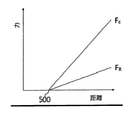
撓み部の剛性が知られている場合、変位の測定値は、有利には、撓み部上の力の大きさを計算するために利用され得る。これは、特に、結合部試験中の力の測定にとって有用である。 If the stiffness of the flexure is known, the displacement measurements can advantageously be used to calculate the magnitude of the force on the flexure. This is especially useful for force measurements during joint test.
[センサ]
センサは、好適には、撓み部の第2端に対して撓み部の第1端が変位する距離の測定値を提供するように構成された変位センサ、すなわち距離センサ、である。センサは、撓み部の第2端に対する撓み部の第1端の変位に対して、理想的には比例関係で変化する出力を提供する任意のセンサであり得る。
[Sensor]
The sensor is preferably a displacement sensor, i.e., a distance sensor configured to provide a measurement of the distance at which the first end of the flexure is displaced relative to the second end of the flexure. The sensor can be any sensor that provides an output that changes in an ideally proportional manner with respect to the displacement of the first end of the flexure with respect to the second end of the flexure.
当該センサは、有利には、撓み部またはセンサ自身に適用される力を直接的には測定しない。従って、当該センサは、歪みゲージではない。歪みゲージとは異なって、当該センサは、変位の測定値を提供するように構成されており、力を直接的に測定するようには構成されていない。 The sensor advantageously does not directly measure the force applied to the bend or the sensor itself. Therefore, the sensor is not a strain gauge. Unlike the strain gauge, the sensor is configured to provide a measurement of displacement, not to measure force directly.
好適には、当該センサは、撓み部への力の適用に応じて変形可能でない。特に好適には、当該センサは、それ自身撓み部に結合されていない。好適には、当該センサは、撓み部の第1端または第2端に対して移動可能であり得て、撓み部の他方の端に対して固定され得る。 Preferably, the sensor is not deformable in response to the application of force to the flexure. Particularly preferably, the sensor is not itself coupled to the flexure. Preferably, the sensor may be movable with respect to the first or second end of the flexure and may be fixed to the other end of the flexure.
力の直接の測定値でなくて変位の測定値を提供して、好適には撓み部への力の適用によって変形されないというセンサは、有利なことに、クリープ現象をほとんど示さない。これらのセンサは、従って、結合部試験中に力を測定するために従来利用されていた圧電抵抗歪みゲージよりも正確性を維持できる。撓み部に取り付けられた歪みゲージは、撓み部が撓む時に本来的に変形されて歪みを生じなければならないため、深刻な撓みの後では完全に回復できない場合があり得て、典型的には時間の経過に従ってクリープ現象を示すようになり、それらの出力が正確でなくなる。更に、歪みゲージが撓み部上の力を測定する場合、例えば接着剤によって、それ自身が撓み部に取り付けられなければならない。そのような接着剤は、歪みゲージの変形中に変形され得て、測定値のクリープ現象の有意な要因となり得る。 A sensor that provides a measurement of displacement rather than a direct measurement of force and is preferably not deformed by the application of force to the flexure, advantageously shows little creep phenomenon. These sensors can therefore maintain greater accuracy than the piezoelectric resistance strain gauges traditionally used to measure forces during joint testing. Strain gauges attached to the flexures may not be fully recoverable after severe flexures, typically because the strain gauges must be inherently deformed to cause strain when the flexures flexure. Over time, they will show creep phenomena and their output will be inaccurate. In addition, if the strain gauge measures force on the bend, it must itself be attached to the bend, for example with an adhesive. Such adhesives can be deformed during the deformation of the strain gauge and can be a significant factor in the creep phenomenon of the measurements.
本発明において用いられるセンサは、好適には、撓み部に力が適用される時、結合部試験中に撓み部に適用されてセンサ自身には適用されない当該力を直接的に受けることがない。このことは、センサの寿命を増大させ、センサにおけるクリープ現象の可能性を低減する。更に、センサ自身が撓み部に結合されない場合、測定値のクリープ現象の要因となり得る接着剤を用いる必要がない。 The sensor used in the present invention preferably does not directly receive the force applied to the flexible portion during the joint test and not applied to the sensor itself when the force is applied to the flexible portion. This increases the life of the sensor and reduces the possibility of creep events in the sensor. Further, if the sensor itself is not coupled to the flexure, it is not necessary to use an adhesive that can cause the creep phenomenon of the measured value.
センサは、好適には、撓み部の第2端に対する撓み部の第1端の変位に比例する出力信号を与えるように構成されている。好適には、センサは、撓み部の変位に正比例する出力信号を与えるように構成されている。 The sensor is preferably configured to give an output signal proportional to the displacement of the first end of the flexure with respect to the second end of the flexure. Preferably, the sensor is configured to give an output signal that is directly proportional to the displacement of the flexure.
結合部試験装置は、センサからの信号、すなわち変位信号、を受容して、当該信号と既知の撓み部の剛性とに基づいて撓み部上の力を決定するように構成されたプロセッサまたはコントローラを備える。プロセッサは、有利には、撓み部上の計算された力に基づいて装置を制御するようにプログラムされ得て、センサは、プロセッサにフィードバックを提供し得て、それに基づいてプロセッサが装置を制御し得る。 The coupling tester is a processor or controller configured to receive a signal from the sensor, i.e., a displacement signal, and determine the force on the flexure based on that signal and the known stiffness of the flexure. Be prepared. The processor can advantageously be programmed to control the device based on the calculated force on the bend, the sensor can provide feedback to the processor, based on which the processor controls the device. obtain.
使用前に、撓み部の剛性は、較正手順によって見出され得る。較正手順においては、撓み部が既知の力で負荷をかけられ、撓み部の第2端に対する撓み部の第1端の変位が測定される。 Prior to use, the stiffness of the flexure can be found by a calibration procedure. In the calibration procedure, the flexed portion is loaded with a known force and the displacement of the first end of the flexed portion with respect to the second end of the flexed portion is measured.
撓み部に適用される力によって歪みゲージ自身が変形されて適用力の直接的な測定値を提供する場合、歪みゲージを用いる装置は、撓み部の剛性に基づいて変位の測定値を力に変換することはない。従って、歪みゲージを用いて撓み部上の力を測定する装置は、センサからの変位信号を受容して当該変位信号と既知の撓み部の剛性とに基づいて撓み部上の力を決定するように構成されたプロセッサを有していない。 If the strain gauge itself is deformed by the force applied to the flexure to provide a direct measurement of the applied force, the device using the strain gauge converts the displacement measurement into a force based on the stiffness of the flexure. There is nothing to do. Therefore, a device that measures the force on the flexure using a strain gauge should receive the displacement signal from the sensor and determine the force on the flexure based on the displacement signal and the known stiffness of the flexure. Does not have a processor configured in.
好適には、センサは、当該センサ自身と別個の検出可能部材との間の変位を検出するように構成され得る。センサは、撓み部の第1端に対して固定され得て、撓み部の第2端に対して固定される検出可能部材に対して、移動可能であり得る。あるいは、センサは、撓み部の第2端に対して固定され得て、撓み部の第1端に対して固定される検出可能部材に対して、移動可能であり得る。従って、センサと検出可能部材との間の変位を検出することによって、センサは、撓み部の第2端に対する撓み部の第1端の変位の測定値を提供し得る。 Preferably, the sensor may be configured to detect the displacement between the sensor itself and a separate detectable member. The sensor may be fixed to the first end of the bend and may be movable relative to a detectable member that is fixed to the second end of the bend. Alternatively, the sensor may be fixed to the second end of the bend and may be movable relative to a detectable member that is fixed to the first end of the bend. Thus, by detecting the displacement between the sensor and the detectable member, the sensor may provide a measured value of the displacement of the first end of the flexure with respect to the second end of the flexure.
例えば、検出可能部材は、磁石であり得て、センサは、磁界を検出するように構成され得る。あるいは、検出可能部材は、金属部材であり得て、センサは、電界の変化を検出するように構成され得る。あるいは、検出可能部材は、スロットが設けられたフォトインタラプタであり得て、センサは、透過光の変化を検出するように構成され得る。 For example, the detectable member can be a magnet and the sensor can be configured to detect a magnetic field. Alternatively, the detectable member may be a metal member and the sensor may be configured to detect changes in the electric field. Alternatively, the detectable member may be a slotted photointerruptor and the sensor may be configured to detect changes in transmitted light.
好適には、センサは、対応する検出可能部材の相対変位に比例する出力を提供するように構成された任意のセンサであり得る。 Preferably, the sensor can be any sensor configured to provide an output proportional to the relative displacement of the corresponding detectable member.
この構成は、有利なことに、正確で再現性のある変位の測定値を提供しながらも、較正及びメンテナンスがシンプルであり得る。例えば、センサ及び検出可能部材の一方が撓み部の第1端に取り付けられ得て、センサ及び検出可能部材の他方が撓み部の第2端に固定された装置の一部の近傍に取り付けられる。センサは、相対的な変位の範囲に亘って較正され得る。この較正は、圧電抵抗歪みゲージよりもセットアップが簡単である。なぜなら、歪みゲージを機能させるためには、それらは、正確な出力レベルを提供する位置で、撓み部に正確に結合される必要があるからである。 This configuration can advantageously be simple to calibrate and maintain while providing accurate and reproducible displacement measurements. For example, one of the sensor and the detectable member may be attached to the first end of the bend, and the other of the sensor and the detectable member may be attached in the vicinity of a portion of the device fixed to the second end of the bend. The sensor can be calibrated over a range of relative displacements. This calibration is easier to set up than a piezoelectric resistance strain gauge. This is because, in order for the strain gauges to work, they need to be precisely coupled to the flex at a position that provides an accurate output level.
結合部試験装置は、磁石部を更に備え得て、センサは、磁界の変化を検出するように構成され得る。磁石部は、磁化された任意の物品または装置の一部であり得るが、好適には固定極の直径磁石(fixed pole diametric magnet)、特に好適には直径方向磁化ディスク磁石(diametrically magnetised disk magnet)である。磁石部またはセンサのいずれか一方が、撓み部の第1端に固定され得て、あるいは撓み部の第1端に対して相対的に固定され得て、磁石部またはセンサの他方が、撓み部の第2端に対して相対的に固定され得て、撓み部の第2端に対する第1端の変位が磁石部をセンサに対して移動させて、センサにおいて経験される磁界の変化をもたらす。センサは、従って、変位センサと称され得る。センサにおける磁界の変化は、有利には、撓み部の変位に比例し得る。 The coupling test apparatus may further include a magnet portion, and the sensor may be configured to detect changes in the magnetic field. The magnet portion may be part of any magnetized article or device, but is preferably a fixed pole diameter magnet, particularly preferably a diametrically magnetized disk magnet. Is. Either the magnet or the sensor can be fixed to the first end of the bend, or it can be fixed relative to the first end of the bend, and the other of the magnet or the sensor is the bend. Can be fixed relative to the second end of the, the displacement of the first end with respect to the second end of the flexure moves the magnet part with respect to the sensor, resulting in the change in magnetic field experienced in the sensor. The sensor can therefore be referred to as a displacement sensor. The change in the magnetic field in the sensor can advantageously be proportional to the displacement of the flexure.
特に好適な実施形態では、センサは、共に結合された2以上のセンサを有し得る。そのような結合されたセンサの配置は、有利には、出力信号の大きさを増大させ得て、装置の感度を増大させる。結合されたセンサは、好適には、何らの力も撓み部に適用されない時に、撓み部の第1端、すなわち選択的には磁石が、2つのセンサの間に位置決めされる、というように構成され得る。撓み部への力の適用時、撓み部の第1端、すなわち選択的には磁石は、結合されたセンサに対して変位する。センサの測定値の範囲は、撓み部の第1端の移動方向に沿って間隔を空けた2以上のセンサまたは2以上の磁石を提供することによって、増大され得る。 In a particularly preferred embodiment, the sensor may have two or more sensors coupled together. The arrangement of such coupled sensors can advantageously increase the magnitude of the output signal and increase the sensitivity of the device. The coupled sensor is preferably configured such that the first end of the flexure, i.e. selectively the magnet, is positioned between the two sensors when no force is applied to the flexure. obtain. When the force is applied to the flexure, the first end of the flexure, or optionally the magnet, is displaced with respect to the coupled sensor. The range of sensor measurements can be increased by providing two or more sensors or two or more magnets spaced along the direction of movement of the first end of the flexure.
[ホール効果センサ]
好適な実施形態では、センサは、磁界の変化に応じてポテンシャル差(電圧)信号を出力するように構成されたホール効果センサである。ホール効果センサは、有利には磁石の近傍に位置決めされて、当該センサが当該磁石の磁界を検出する。センサに対する磁石の変位は、センサにおける磁界の変化をもたらし、磁石の変位に正比例するポテンシャル差をセンサにおいて生成する。磁石またはホール効果センサの一方が、撓み部の第1端に対して相対的に固定され得て、磁石またはホール効果センサの他方が、撓み部の第2端に対して相対的に固定され得る。ホール効果センサからの出力信号は、センサに対する磁石の変位に比例して、ホール効果センサは、撓み部の第1端の変位の測定値を提供する。ホール効果センサは、従って、変位センサと称され得る。
[Hall effect sensor]
In a preferred embodiment, the sensor is a Hall effect sensor configured to output a potential difference (voltage) signal in response to changes in the magnetic field. The Hall effect sensor is advantageously positioned in the vicinity of the magnet, which senses the magnetic field of the magnet. The displacement of the magnet with respect to the sensor results in a change in the magnetic field in the sensor, producing a potential difference in the sensor that is directly proportional to the displacement of the magnet. One of the magnets or Hall effect sensors can be fixed relative to the first end of the bend, and the other of the magnets or Hall effect sensors can be fixed relative to the second end of the bend. .. The output signal from the Hall effect sensor is proportional to the displacement of the magnet with respect to the sensor, and the Hall effect sensor provides a measurement of the displacement of the first end of the flexure. Hall effect sensors can therefore be referred to as displacement sensors.
ホール効果センサは、有利なことに、磁界の小さな変化に応じて、相対的に大きな線形出力を生成する。例えば、本発明における使用にとって好適なホール効果センサは、2mmの磁石の相対変位に応じて、数ボルトの大きさの出力信号を提供し得る。これは、ホール効果センサが、その大きさが結合部テスタ内の力を測定するために典型的に利用されていた従来の歪みゲージの出力よりも有意に高い出力信号をもたらす、ことを意味する。ホール効果センサからの出力の大きさが大きいことは、処理のためにプロセッサに当該信号を供給する前に、センサからの出力信号を増幅する必要がないことを意味する。これは、歪みゲージを用いて力を測定するシステムよりも本発明の装置がより少ない電気的要素のみを要求し得て、測定される値へ導入され得る潜在的な誤差要因が少ない、ということを意味する。 The Hall effect sensor advantageously produces a relatively large linear output in response to small changes in the magnetic field. For example, a Hall effect sensor suitable for use in the present invention may provide an output signal as large as a few volts, depending on the relative displacement of the 2 mm magnet. This means that the Hall effect sensor yields a significantly higher output signal than the output of conventional strain gauges whose magnitude was typically used to measure force within a junction tester. .. The high magnitude of the output from the Hall effect sensor means that it is not necessary to amplify the output signal from the sensor before supplying the signal to the processor for processing. This means that the device of the invention can require only fewer electrical components than a system that measures forces using strain gauges, and there are fewer potential error factors that can be introduced into the measured values. Means.
一例として、撓み部に取り付けられる典型的な従来技術による箔歪みゲージは、10Vの励起電圧を要求するブリッジ形態で構成され得て、完全な負荷時において0.0123Vの出力電圧を与え得る。本発明によるホール効果センサを用いる同様の撓み部は、完全な負荷時において約2.0Vの出力を与え得て、従って当該電圧を測定する前の増幅が不要である。ホール効果センサは、それらがクリープ現象に対する優れた抵抗を示すため、本発明における変位の測定に利用する上で特に有利であり得る。 As an example, a typical prior art foil strain gauge attached to a bend can be configured in a bridge configuration requiring an excitation voltage of 10 V and can provide an output voltage of 0.0123 V at full load. A similar flexure using the Hall effect sensor according to the invention can provide an output of about 2.0 V under full load and therefore does not require amplification prior to measuring the voltage. Hall effect sensors can be particularly advantageous for use in measuring displacement in the present invention as they exhibit excellent resistance to creep phenomena.
好適な実施形態によれば、本発明は、結合部試験の間に結合部に接触するように構成された試験ツールを有する試験ツールアセンブリを備えた結合部試験装置であり得る。当該結合部試験装置は、更に、試験ツールアセンブリに結合された撓み部と、磁石と、ホール効果センサと、を備える。磁石とセンサとの内の一方が、撓み部の第1端に対して相対的に固定され、磁石とセンサとの内の他方が、撓み部の第2端に対して相対的に固定され、ホール効果センサは、撓み部への力の適用時に撓み部の第1端が撓み部の第2端に対して変位する時の磁界の変化を検出するように構成されている。結合部試験装置は、好適には、ホール効果センサからの信号を受容し、当該信号と既知の撓み部の剛性とに基づいて撓み部上の力を計算するように構成されたプロセッサを含んでいる。 According to a preferred embodiment, the invention may be a joint test apparatus comprising a test tool assembly having a test tool configured to contact the joint during the joint test. The joint test apparatus further comprises a bend coupled to the test tool assembly, a magnet, and a Hall effect sensor. One of the magnet and the sensor is fixed relative to the first end of the flexure, and the other of the magnet and the sensor is relatively fixed to the second end of the flexure. The Hall effect sensor is configured to detect a change in the magnetic field when the first end of the flexed portion is displaced with respect to the second end of the flexed portion when a force is applied to the flexed portion. The joint tester preferably includes a processor configured to receive a signal from the Hall effect sensor and calculate the force on the bend based on the signal and the known stiffness of the bend. There is.
[可能性あるセンサ]
ホール効果センサの代わりに、あるいは、ホール効果センサに加えて、センサは、光学的変位センサであってもよい。例えば、センサは、スロットが設けられたフォトインタラプタ、飛行時間センサ(ToFセンサ)、あるいは、光学的三角測量センサであってもよい。センサは、磁気抵抗センサ、巨大磁気抵抗センサ、または、静電容量センサであってもよい。
[Potential sensor]
Instead of the Hall effect sensor, or in addition to the Hall effect sensor, the sensor may be an optical displacement sensor. For example, the sensor may be a slotted photointerruptor, a flight time sensor (ToF sensor), or an optical triangulation sensor. The sensor may be a magnetoresistive sensor, a giant magnetoresistive sensor, or a capacitance sensor.
[撓み部]
好適には、本発明装置は、1より多い撓み部を備えていて、それらの撓み部の第1端同士が、互いに結合されて、それらの撓み部の第1端同士は、力の適用時に、同じ距離だけ変位する。撓み部は、当該技術分野で知られているような、折り畳まれた形態のビームによる撓み部、蛇行した撓み部、あるいは、直線状の(折り畳まれていない)撓み部、であり得る。特に好適には、本発明装置は、当該撓み部の第1端同士が第2端同士に対して直線状の軸線に沿ってのみ移動可能であるように構成された2以上の撓み部を有する。例えば、本発明装置は、鉛直面内において互いに上下に配置された同じ長さの一対の撓み部を備え得て、当該撓み部の第1端同士が共に結合されて鉛直軸線に沿ってのみ移動可能であり得る。そのような形態は、撓み部の横方向変位を排除ないし低減し得て、撓み部の第1端同士が常に直線状に変位することを保証し、センサは、単一軸に沿って移動を測定するように構成され得る。
[Flexible part]
Preferably, the apparatus of the present invention comprises more than one bends, the first ends of the bends are coupled to each other, and the first ends of the bends are at the time of application of force. , Displace by the same distance. The bend can be a bent beam bend, a meandering bend, or a linear (unfolded) bend, as is known in the art. Particularly preferably, the apparatus of the present invention has two or more flexible portions configured so that the first ends of the flexible portions can move only along a linear axis with respect to the second ends. .. For example, the apparatus of the present invention may include a pair of flexible portions of the same length arranged one above the other in a vertical plane, and the first ends of the flexible portions are coupled together and move only along the vertical axis. It can be possible. Such a form can eliminate or reduce lateral displacement of the flexure, ensuring that the first ends of the flexure are always linearly displaced, and the sensor measures movement along a single axis. Can be configured to.
撓み部は、試験ツールが当該撓み部の一端に固定される、というように構成され得て、試験ツールと試験対象の結合部との間の試験力の適用が、当該撓み部を撓ませ得る。そのような構成では、センサは、試験ツールと結合部との間の試験力の大きさを決定するために利用され得る。あるいは、撓み部は、引張試験ツールの顎部上の閉鎖力のような異なる力に応じて撓むように構成された撓み部であり得る。この構成では、センサは、顎部上の閉鎖力の大きさを決定するために利用され得る。 The flexure can be configured such that the test tool is fixed to one end of the flexure, and the application of test force between the test tool and the joint to be tested can flex the flexure. .. In such a configuration, the sensor can be utilized to determine the magnitude of the test force between the test tool and the joint. Alternatively, the flexure can be a flexure configured to flex in response to a different force, such as a closing force on the jaw of a tensile test tool. In this configuration, the sensor can be utilized to determine the magnitude of the closing force on the jaw.
[試験ツール]
試験ツールは、撓み部の第1端に固定され得て、結合部による試験ツールへの試験力の適用が、撓み部の第1端の所定方向の変位を引き起こす。センサは、好適には、当該変位の大きさを提供するように構成され、撓み部の第1端の変位と撓み部の既知の剛性とを用いて、撓み部上の力、すなわち試験力が計算され得る。
[Test tool]
The test tool can be anchored to the first end of the bend, and the application of test force to the test tool by the joint causes displacement of the first end of the bend in a predetermined direction. The sensor is preferably configured to provide the magnitude of the displacement, using the displacement of the first end of the flexure and the known stiffness of the flexure to create a force on the flexure, i.e., a test force. Can be calculated.
試験ツールは、特定のタイプの結合部試験に使用するように構成され得る。例えば、試験ツールは、結合部を把持するように構成されたピンセット状の顎部を有する常温式バンププル(Cold Bump Pull:CBP)試験ツールであり得る。当該試験ツールは、結合部に剪断力を適用するように構成された剪断試験ツールであってもよい。あるいは、当該試験ツールは、押圧試験ツールであってもよい。当該試験ツールは、有利には、熱伝達性材料から製造され、好適には、高い熱伝導率を有する材料から製造される。特に好適には、試験ツールは、金属から形成される。 The test tool may be configured for use in certain types of joint tests. For example, the test tool can be a Cold Bump Pull (CBP) test tool with a tweezers-like jaw configured to grip the joint. The test tool may be a shear test tool configured to apply a shear force to the joint. Alternatively, the test tool may be a pressing test tool. The test tool is advantageously made from a heat transferable material and preferably from a material having a high thermal conductivity. Particularly preferably, the test tool is made of metal.
試験ツールは、結合部試験の間に結合部に接触するように構成された試験ツールチップを有する。 The test tool has a test tooltip configured to contact the joint during the joint test.
[駆動機構]
好適な実施形態では、本発明の結合部試験装置は、結合部試験の間に試験ツールの顎部によって結合部に適用される閉鎖力、すなわち把持力、を測定するように構成され得る。
[Drive mechanism]
In a preferred embodiment, the joint test apparatus of the present invention may be configured to measure the closing force, i.e., gripping force, applied to the joint by the jaw of the test tool during the joint test.
試験ツールは、対向する顎部を有し得て、試験ツールアセンブリは、閉鎖部材と、当該閉鎖部材に駆動力を適用するように構成された駆動機構と、を有し得て、閉鎖部材は顎部に閉鎖力を適用し得る。適用される閉鎖力が不在である場合、対向する顎部は、好適には、互いから間隔を空けた開放位置に戻る。閉鎖部材は、好適には、駆動機構からの駆動力を試験ツールの顎部の閉鎖力に変換するように構成されている。使用中、顎部への閉鎖力の適用は、顎部を強制的に近づけさせ、顎部はその間に位置決めされた結合部と接触してこれを把持する。 The test tool may have opposed jaws and the test tool assembly may have a closing member and a driving mechanism configured to apply a driving force to the closing member, the closing member. Closing force can be applied to the jaw. In the absence of the closing force applied, the opposing jaws preferably return to open positions spaced apart from each other. The closing member is preferably configured to convert the driving force from the driving mechanism into the closing force of the jaw of the test tool. During use, the application of a closing force to the jaw forces the jaw closer and the jaw contacts and grips the joint positioned in between.
好適には、駆動機構は、駆動力を閉鎖部材に適用する間に当該駆動機構によって移動される距離を測定するように構成された駆動機構距離センサを有する。駆動機構距離センサは、エンコーダであり得て、例えば、駆動機構が所定の直線方向または角度方向にどの程度移動したかを測定するように構成されたロータリエンコーダやリニアエンコーダであり得る。 Preferably, the drive mechanism has a drive mechanism distance sensor configured to measure the distance traveled by the drive mechanism while the drive force is applied to the closing member. The drive mechanism distance sensor can be an encoder, for example, a rotary encoder or a linear encoder configured to measure how much the drive mechanism has moved in a predetermined linear or angular direction.
好適には、結合部試験装置は、試験ツールの顎部間の分離ないし距離を測定するように構成されている。結合部試験装置は、ロータリエンコーダやリニアエンコーダのような駆動機構距離センサを用いて試験ツールの顎部間の分離を測定するように構成され得る。試験ツールの顎部間の分離を測定することは、有利なことに、特定の結合部試験動作のために顎部が所定の分離状態に開放されることを許容し得る。例えば、顎部は、既知の方法によって当該顎部の内側を清掃することを許容する所定の清掃用分離状態に開放可能であり得る。顎部は、所定の試験前分離状態に開放可能であってもよい。当該試験前分離状態とは、試験対象の結合部のサイズよりも大きく、試験対象の結合部の周囲に顎部を位置決めする前の状態である。顎部の分離を測定することは、従って有利なことに、動作中の試験ツールのより正確な位置決めを許容し得る。 Preferably, the joint test device is configured to measure the separation or distance between the jaws of the test tool. The joint test device may be configured to measure the separation between the jaws of the test tool using a drive mechanism distance sensor such as a rotary encoder or linear encoder. Measuring the separation between the jaws of the test tool may advantageously allow the jaws to be opened to a given separation state for a particular joint test operation. For example, the jaw may be open to a predetermined cleaning separation state that allows cleaning the inside of the jaw by known methods. The jaw may be openable to a predetermined pre-test separation state. The pre-test separation state is a state before the jaw is positioned around the joint to be tested, which is larger than the size of the joint to be tested. Measuring jaw separation can therefore advantageously allow for more accurate positioning of the test tool in motion.
駆動機構は、好適には、試験ツールの顎部が結合部を把持する時、駆動力の適用が撓み部の第2端に対して第1端を変位させる、というように構成される。好適には、駆動機構及び/または閉鎖部材は、顎部が結合部に接触するまで、駆動力の閉鎖部材への適用が撓み部を変位させない、というように構成される。試験ツールの顎部が結合部に接触すると、更なる駆動力(閉鎖力)の適用は、結合部材料からの抵抗に会って、結合部が顎部に反力を与える。当該反力の大きさは、有利には、顎部によって結合部に作用される閉鎖力の大きさに正比例し得る。この反力は、試験ツールから閉鎖部材を介して駆動機構にまで伝達される。駆動機構は、好適には、この反力によって顎部の閉鎖力に比例する距離だけ撓み部の第1端が第2端に対して変位する、というように構成される。 The drive mechanism is preferably configured such that when the jaw of the test tool grips the joint, the application of the driving force displaces the first end with respect to the second end of the flexure. Preferably, the drive mechanism and / or the closing member is configured such that the application of the driving force to the closing member does not displace the flexure until the jaw contacts the joint. When the jaw of the test tool comes into contact with the joint, the application of additional driving force (closing force) meets the resistance from the joint material and the joint exerts a reaction force on the jaw. The magnitude of the reaction force can advantageously be directly proportional to the magnitude of the closing force exerted by the jaw on the joint. This reaction force is transmitted from the test tool to the drive mechanism via the closing member. The drive mechanism is preferably configured such that the reaction force causes the first end of the flexed portion to be displaced with respect to the second end by a distance proportional to the closing force of the jaw portion.
好適な実施形態では、駆動機構は、撓み部の第1端に取り付けられており、撓み部の第1端は、試験ツールに対して移動可能である。試験ツールの位置は、使用中、撓み部の第2端に対して固定され得る。好適には、駆動機構は、試験ツールの顎部が結合部を把持する時、駆動力の適用が、駆動機構に作用して撓み部の第1端を第2端に対して変位させる反力を生成する、というように構成される。この配置において、反力の大きさは、顎部によって結合部に作用される閉鎖力の大きさに比例し、撓み部上の力は、当該反力に比例する。撓み部上の力を測定することは、従って、顎部によって結合部に作用される閉鎖力の測定値を提供する。 In a preferred embodiment, the drive mechanism is attached to the first end of the bend, which is movable with respect to the test tool. The position of the test tool may be fixed relative to the second end of the bend during use. Preferably, the drive mechanism is a reaction force in which the application of the drive force acts on the drive mechanism to displace the first end of the flexure with respect to the second end when the jaw of the test tool grips the joint. Is generated, and so on. In this arrangement, the magnitude of the reaction force is proportional to the magnitude of the closing force exerted on the joint by the jaw, and the force on the flexure is proportional to the reaction force. Measuring the force on the flexure therefore provides a measure of the closing force exerted on the joint by the jaw.
装置内の摩擦力の作用は、有利には、低摩擦材料及び/または潤滑剤を用いることによって最小化され得る。摩擦力は、較正によって補償され得る。 The effect of frictional forces within the device can be advantageously minimized by the use of low friction materials and / or lubricants. Friction forces can be compensated by calibration.
駆動機構は、好適には、電気モータである。それは、ギヤ付き電気モータであり得る。駆動機構は、好適には、リードネジとナットとを更に有する。ナットは、リードネジ上に取り付けられ得て、好適には、それが回転できないように構成される。モータは、リードネジを回転するように構成され得て、モータによるリードネジの回転時に、ナットはリードネジに対して移動可能である。駆動機構は、好適には、リードネジに対するナットの移動が駆動力を閉鎖部材に適用する、というように構成される。 The drive mechanism is preferably an electric motor. It can be a geared electric motor. The drive mechanism preferably further comprises a lead screw and a nut. The nut can be mounted on the lead screw and is preferably configured to prevent it from rotating. The motor may be configured to rotate the lead screw so that the nut is movable relative to the lead screw as the motor rotates the lead screw. The drive mechanism is preferably configured such that the movement of the nut with respect to the lead screw applies the driving force to the closing member.
好適な実施形態では、駆動機構は、レバーを更に有し、ナットはレバーの第1端と移動可能に係合され、レバーは回動点回りに回動可能である。レバーの利用は、駆動機構からの力を増幅し、十分な駆動力を提供するために選択的にパワーのより小さい駆動機構、例えばより小型のモータ、の使用を許容し得る。駆動機構は、レバーの第1端に力を適用し得て、回動点の両側のレバーの長さの比の結果として、それは第2端におけるより大きな力に帰結する。 In a preferred embodiment, the drive mechanism further comprises a lever, the nut is movably engaged with the first end of the lever, and the lever is rotatable around a rotation point. The use of the lever may allow the use of a drive mechanism with a selectively smaller power, such as a smaller motor, to amplify the force from the drive mechanism and provide sufficient drive force. The drive mechanism may apply a force to the first end of the lever, which results in a greater force at the second end as a result of the ratio of the lengths of the levers on either side of the turning point.
好適には、駆動機構は、使用中、リードネジに沿ったナットの移動がレバーの第1端を移動させて、レバーがその回転点回りに回動する、というように構成される。 Preferably, the drive mechanism is configured such that during use, the movement of the nut along the lead screw moves the first end of the lever so that the lever rotates around its rotation point.
好適には、レバーは、その第1端と反対側の第2端回りに回動可能であり得る。 Preferably, the lever may be rotatable around a second end opposite its first end.
好適には、レバーは、閉鎖部材に当接するように配置されたカム機構を有し、当該カム機構は、第2端回りのレバーの回動によってカムが閉鎖部材に駆動力を適用する、というように構成されている。レバー及びカムの使用は、有利なことに、駆動力及び/または閉鎖部材を介して駆動機構に戻るように伝達される反力の大きさを増幅し得て、駆動機構の小さな行程がより大きな駆動力を閉鎖部材に適用可能であり、及び、反力が撓み部のより大きな変位を引き起こしてより高い精度で測定可能である。 Preferably, the lever has a cam mechanism arranged to abut on the closing member, wherein the cam applies a driving force to the closing member by rotation of the lever around the second end. It is configured as follows. The use of levers and cams can advantageously amplify the magnitude of the drive force and / or the reaction force transmitted back to the drive mechanism via the closing member, resulting in a larger small stroke of the drive mechanism. The driving force can be applied to the closing member, and the reaction force causes a larger displacement of the flexure and can be measured with higher accuracy.
駆動機構がモータを有している場合、駆動機構距離センサは、駆動力の適用中にモータが移動する距離を測定するように構成されたエンコーダであり得る。例えば、エンコーダは、モータまたはリードネジによって実施される回転数を計数可能である。 If the drive mechanism has a motor, the drive mechanism distance sensor can be an encoder configured to measure the distance the motor travels during the application of the drive force. For example, the encoder can count the number of revolutions performed by the motor or lead screw.
好適には、リードネジは、ファインピッチを有するネジ部を有しており、リードネジに沿って所与の直線距離だけナットが移動するために、比較的高い回転数が要求される。これは、有利なことに、ナットの高分解能の直線起動を許容し、エンコーダはナットの直線移動について高いエンコーダ数値を測定する。これは、好適にはギヤ付きモータ及びレバーカムと組み合わされて、モータのパワー要求を低減し、カム面に高い駆動力を適用する間に駆動機構によって移動される距離の正確な測定を許容する。 Preferably, the lead screw has a threaded portion having a fine pitch, and a relatively high rotation speed is required for the nut to move along the lead screw by a given linear distance. This advantageously allows a high resolution linear start of the nut and the encoder measures a high encoder value for the linear movement of the nut. It is preferably combined with a geared motor and a lever cam to reduce the power demand of the motor and allow an accurate measurement of the distance traveled by the drive mechanism while applying high driving force to the cam surface.
[閉鎖部材]
閉鎖部材は、試験ツールの顎部の少なくとも一部を取り囲むように配置されたスリーブないしコレットを有し得る。スリーブは、試験ツールに対して軸方向に移動可能、すなわち、試験ツールの軸線に沿って移動可能であり得る。スリーブは、好適には、使用中、顎部に対する当該スリーブの移動が顎部に閉鎖力を適用する、というように顎部と係合するように構成される。
[Closed member]
The closing member may have a sleeve or collet arranged to surround at least a portion of the jaw of the test tool. The sleeve may be axially movable with respect to the test tool, i.e., move along the axis of the test tool. The sleeve is preferably configured to engage the jaw during use such that the movement of the sleeve with respect to the jaw applies a closing force to the jaw.
好適な実施形態では、顎部の各々の外面が顎部の先端に向かって幅広になっており、スリーブの一部は、その直径が開放形態の顎部の外面の直径よりも小さい、といいうように構成される。これにより、顎部の先端に向かうスリーブの相対移動が、顎部を共に押し付けて近づける閉鎖力を適用する。好適には、スリーブは、顎部の先端から離れる方向に付勢されていて、駆動機構が、スリーブを顎部の先端に向けて移動する方向に駆動力を適用するように構成されている。この文脈において、「先端」とは、試験中に結合部と係合する顎部の端部を意味する。もっとも、顎部の先端から離れるスリーブの移動が顎部を共に近づける、というように機構を設計することも可能である。 In a preferred embodiment, it is said that each outer surface of the jaw is widened towards the tip of the jaw and part of the sleeve is smaller in diameter than the outer surface of the open jaw. It is configured as follows. Thereby, the relative movement of the sleeve toward the tip of the jaw applies a closing force that pushes the jaw together and brings them closer. Preferably, the sleeve is urged away from the tip of the jaw and the drive mechanism is configured to apply the driving force in the direction of moving the sleeve towards the tip of the jaw. In this context, "tip" means the end of the jaw that engages the joint during the test. However, it is also possible to design the mechanism so that the movement of the sleeve away from the tip of the jaw brings the jaws closer together.
特に好適には、スリーブは、低摩擦材料から形成され、スリーブと顎部と間の摩擦力が、使用中、顎部への閉鎖力より、少なくとも10倍、あるいは15倍、あるいは20倍、小さい。このことは、摩擦に起因する損失が極端に低いか無視できる状態で、スリーブが駆動力を閉鎖力として顎部に伝達することを許容し、顎部によって結合部に作用される閉鎖力が正確に測定されることを保証する。 Particularly preferably, the sleeve is made of a low friction material and the frictional force between the sleeve and the chin is at least 10 times, 15 times, or 20 times less than the closing force to the chin during use. .. This allows the sleeve to transmit the driving force as a closing force to the jaw, with extremely low or negligible loss due to friction, and the closing force exerted by the jaw on the joint is accurate. Guarantee that it will be measured.
特に好適な実施形態では、スリーブは、顎部の一部の周りに同心に配置されたセラミック製のカラーであり、使用中、当該セラミック製のカラーは顎部に接触して顎部を共に押し付けて近づける。セラミック製のカラーは、有利なことに、スリーブと試験ツールの顎部との間の低摩擦接触面を提供する。 In a particularly preferred embodiment, the sleeve is a ceramic collar concentrically placed around a portion of the chin, the ceramic collar in contact with the chin and pressing the chin together. Get closer. The ceramic collar advantageously provides a low friction contact surface between the sleeve and the jaw of the test tool.
本発明において顎部の少なくとも一部を取り囲むように配置されたスリーブの使用、選択的にはセラミック製のカラーの使用は、有利なことに、顎部に適用される閉鎖力の同心性を改善し得る。本発明のスリーブは、同じ力が各試験ツールの顎部に均等に適用されるように、閉鎖力を分散させることを助ける。これは、特に、典型的には直径が20~800ミクロンのサイズ範囲である、はんだバンプを把持する時に有利である。なぜなら、当該スケールでの同心性の欠如は、信頼性のない試験結果をもたらし得るからである。 In the present invention, the use of sleeves arranged to surround at least a portion of the jaw, optionally the use of a ceramic collar, advantageously improves the concentricity of the closing forces applied to the jaw. Can be. The sleeves of the present invention help distribute the closing force so that the same force is evenly applied to the jaws of each test tool. This is particularly advantageous when gripping solder bumps, typically in the size range of 20-800 microns in diameter. This is because the lack of concentricity on the scale can lead to unreliable test results.
好適には、閉鎖部材及び/または試験ツールは、試験ツールの顎部が幾つかの段階で閉鎖することを制御可能であるように、構成され得る。例えば、第1形態において、試験ツールの顎部は完全に開放され得て、顎部の内部が点検及び清掃され得る。第2形態において、顎部の分離が試験対象の結合部の直径よりも丁度大きいというように閉鎖部材が顎部を閉鎖し得て、顎部は試験対象の基板上の他の結合部と接触することなく結合部上に載置され得る。第3形態において、閉鎖部材は試験ツールの顎部を閉鎖して、それらが結合部を把持して結合部に閉鎖力を作用させる。装置が第3形態にある時、前述のように更なる駆動力の適用が反力を生成し、当該反力が撓み部の第1端の変位をもたらし、当該変位がセンサによって測定される。試験ツールの顎部によって結合部に作用される閉鎖力を計算するために、センサからの信号が、撓み部の既知の剛性と共に利用され得る。 Preferably, the closure member and / or the test tool may be configured such that the jaw of the test tool can be controlled to close at several stages. For example, in the first embodiment, the jaw of the test tool can be completely opened and the inside of the jaw can be inspected and cleaned. In the second embodiment, the closing member can close the jaw such that the jaw separation is just larger than the diameter of the joint under test, and the jaw is in contact with other joints on the substrate under test. Can be placed on the joint without any effort. In a third embodiment, the closing member closes the jaw of the test tool, which grips the joint and exerts a closing force on the joint. When the device is in the third form, the application of additional driving force as described above produces a reaction force, which causes the displacement of the first end of the flexure, and the displacement is measured by the sensor. A signal from the sensor can be utilized with the known stiffness of the flexure to calculate the closing force exerted on the joint by the jaw of the test tool.
[第2撓み部]
好適な実施形態では、試験ツールアセンブリ、第1センサ、及び、第1撓み部が、第2撓み部の第1端に取り付けられている。第2撓み部の第1端は、第2撓み部の第2端に対して移動可能であり、当該装置は、更に、第2センサを有しており、当該第2センサは、結合部による試験ツールへの試験力の適用時に第2撓み部の第1端の第2撓み部の第2端に対する変位を測定するように構成されている。
[Second bending part]
In a preferred embodiment, the test tool assembly, the first sensor, and the first flexure are attached to the first end of the second flexure. The first end of the second flexure is movable with respect to the second end of the second flexure, the device further comprises a second sensor, the second sensor of which is by the coupling. It is configured to measure the displacement of the first end of the second flexure with respect to the second end of the second flexure when the test force is applied to the test tool.
試験ツールアセンブリ、センサ及び撓み部は、試験ツールの顎部によって結合部上に作用される閉鎖力を測定するように構成され得る。 The test tool assembly, sensor and flexure can be configured to measure the closing force exerted on the joint by the jaw of the test tool.
好適には、前述のように、試験ツールアセンブリ、第1センサ、及び、第1撓み部が、試験ツールの顎部によって結合部に作用される閉鎖力を測定するように構成される。換言すれば、試験ツールアセンブリが、前述のような閉鎖部材と駆動機構とを有し得て、第2撓み部上の力とは独立に閉鎖力を測定するように構成され得る。 Preferably, as described above, the test tool assembly, the first sensor, and the first flexure are configured to measure the closing force exerted on the joint by the jaw of the test tool. In other words, the test tool assembly may have the closing member and drive mechanism as described above and may be configured to measure the closing force independently of the force on the second flexure.
特に好適には、試験ツールは、第2撓み部の第1端に対して相対的に固定され、結合部による試験ツールへの試験力の適用が、第2撓み部の第1端の変位を引き起こす。第2センサと既知の第2撓み部の剛性とを用いて、前述のように、試験ツール上の試験力が計算され得る。 Particularly preferably, the test tool is fixed relative to the first end of the second flexure, and the application of the test force to the test tool by the joint causes the displacement of the first end of the second flexure. cause. Using the second sensor and the known stiffness of the second flexure, the test force on the test tool can be calculated as described above.
この構成を用いることで、有利なことに、試験ツールの顎部上の閉鎖力と試験ツール上の試験力との両方が測定され得る。使用中、結合部の上方に試験ツールを位置決めし、顎部が結合部上に閉鎖力を作用させるように駆動機構を作動させて第1撓み部の変位を引き起こす反力を生成し、第1撓み部の変位を測定し、第1撓み部の既知の剛性を用いて顎部間の閉鎖力を計算する、という工程によって、閉鎖力が最初に測定され得る。
次いで、試験力が試験ツールと結合部との間に適用され、第2撓み部の第1端が変位する。第2センサが第2撓み部の変位の測定値を提供し、第2撓み部上の試験力が、第2撓み部の既知の剛性を用いて計算され得る。
By using this configuration, it is advantageous that both the closing force on the jaw of the test tool and the test force on the test tool can be measured. During use, the test tool is positioned above the joint and the drive mechanism is actuated so that the jaw exerts a closing force on the joint to generate a reaction force that causes displacement of the first flexure, the first. The closing force can be first measured by the process of measuring the displacement of the flexure and calculating the closure force between the jaws using the known stiffness of the first flexure.
The test force is then applied between the test tool and the joint to displace the first end of the second flexure. A second sensor provides a measured value of the displacement of the second flexure, and the test force on the second flexure can be calculated using the known stiffness of the second flexure.
[光案内部]
結合部試験の実施の際、正確な事前位置決め(整列)と試験のセットアップ、試験中のビデオ録画及び試験の視覚的検査、並びに、試験完了後の結合部及び試験ツールの引き続いての視覚的検査、を許容するために、試験対象の結合部を十分な光で照明することが必要である。
[Light guide]
Precise pre-positioning (alignment) and test setup, video recording during the test and visual inspection of the test, as well as subsequent visual inspection of the joint and test tools after the test is completed. It is necessary to illuminate the joint under test with sufficient light to allow.
結合部試験機械は、典型的には、光の茎(stalk)が適用されている。それは、光を伴う(透過する)柔軟な茎部材であり、自由端で適合している。これらは、結合部試験機械に固定されており、試験片を照明するべく所定位置内に操作され得る。しかしながら、この態様で証明を提供することは、幾つかの問題を生じる。光の茎は、かさばるため(bulky)、結合部試験機械の他の要素と干渉し得る。光源の位置は、不可避的に、影及び一定でない照明領域が存在することを意味する。光の茎は、不所望に(accidentally)移動され得るため、頻繁な再調整を要求し得る。光源が離れた位置にある場合、微小試験片と共に利用される照明を最適化することができない。微小試験片は、より一般的になりつつある。この文脈において、微小とは、20~100μm(ミクロン)の範囲を意味する。 The joint test machine is typically applied with a stalk of light (stalk). It is a flexible stem member with (transmitting) light and is fitted at the free end. These are fixed to the joint test machine and can be manipulated in place to illuminate the test piece. However, providing proof in this embodiment raises some problems. The stem of light is bulky and can interfere with other elements of the joint test machine. The location of the light source inevitably means the presence of shadows and non-constant illumination areas. Since the stem of light can be moved accidentally, frequent readjustments may be required. If the light source is distant, the lighting used with the microtest piece cannot be optimized. Microtest pieces are becoming more common. In this context, micro means the range of 20-100 μm (micron).
好適には、結合部試験装置は、試験ツールに対して相対的に固定された1または複数の光源を備えており、前記1または複数の光源からの光を前記試験ツールチップに向けるように構成されている。 Preferably, the joint test apparatus comprises one or more light sources that are relatively fixed relative to the test tool and is configured to direct light from the one or more light sources to the test tooltip. Has been done.
1または複数の光源は、少なくとも1つの強度可変の光源を有していてもよい。 The one or more light sources may have at least one variable intensity light source.
好適な実施形態では、1または複数の光源は、少なくとも1つの発光ダイオード(LED)を有している。1または複数の光源は、試験ツールの周囲に配置され光案内部内へと発光するよう構成された複数のLEDを含み得る。 In a preferred embodiment, the one or more light sources have at least one light emitting diode (LED). The one or more light sources may include a plurality of LEDs arranged around the test tool and configured to emit light into the light guide.
特に好適には、本発明装置は、試験ツールに対して相対的に固定されて1または複数の光源からの光を試験ツールチップに向けるように構成された光案内部を備える。 Particularly preferably, the apparatus of the present invention comprises a light guide configured to be fixed relative to the test tool and configured to direct light from one or more light sources towards the test tooltip.
試験ツールチップを照明するための光案内部の使用は、本発明による結合部試験装置にとって、特に微小の試験片を試験する際、特に有利であり得る。光案内部は、また、“顎部を有する”試験ツールを用いる場合に特に有利であり得る。例えば、CBP試験は、試験対象の結合部周りに正確に位置決めされなければならない一対の顎部を有する試験ツールを用いるため、光案内部は、有利に、試験ツールチップと試験対象の結合部とを照明可能である。これは、試験前に試験ツールを正確に位置決めすることをより容易にする。 The use of a light guide to illuminate the test tooltip can be particularly advantageous for the joint test apparatus according to the invention, especially when testing microscopic test pieces. Optical guides can also be particularly advantageous when using test tools that have a "jaw". For example, because the CBP test uses a test tool with a pair of jaws that must be accurately positioned around the joint to be tested, the light guide is advantageous for the joint between the test tooltip and the joint to be tested. Can be illuminated. This makes it easier to accurately position the test tool prior to testing.
光案内部は、当該光案内部内の光の全内反射によって、前記1または複数の光源からの光を前記試験ツールチップに案内し得る。光は、光案内部の固体状の半透明ないし透明の材料を通過し得る。代替的に、あるいは追加的に、光案内部は、中空であり得て、光は光案内部の内部反射面から反射し得る。有利には、光案内部は、1または複数の離れた光源からの光を試験ツールチップの周囲の小領域へと効率良く案内する。これは、低電力の光源が利用されることを許容し、また、影無しの照明を提供し得る。 The light guide unit may guide the light from the one or more light sources to the test tooltip by total internal reflection of the light in the light guide unit. Light can pass through a solid translucent or transparent material in the light guide. Alternatively or additionally, the optical guide may be hollow and light may be reflected from the internal reflective surface of the optical guide. Advantageously, the light guide efficiently guides light from one or more distant light sources to a small area around the test tooltip. This allows low power light sources to be utilized and may also provide shadowless lighting.
光案内部は、試験ツールチップ上に光を焦点合わせするように構成され得る。光案内部は、試験ツールチップの周囲の所定領域を照明するように構成されたレンズを有し得る。光案内部は、試験ツールチップに向けて先細状(テーパ状)であり得る。光案内部の先細状部分は、試験ツールチップに向けて光を案内するように構成され得る。実施される試験のタイプと照明が望まれる領域とに依存して、異なる照明パターンを提供するべく異なる光源が利用され得る。光源は、光の可変の焦点合わせを提供するべく、互いに対して移動可能な2以上の部分を有し得る。 The light guide may be configured to focus the light on the test tooltip. The light guide may have a lens configured to illuminate a predetermined area around the test tooltip. The optical guide may be tapered towards the test tooltip. The tapered portion of the light guide may be configured to guide light towards the test tooltip. Different light sources may be utilized to provide different lighting patterns, depending on the type of test performed and the area where lighting is desired. A light source may have two or more portions that are movable relative to each other to provide variable focusing of light.
光案内部は、試験ツールの周囲に適合するように構成された管状体を有し得て、光案内部は、当該光案内部の基端から当該光案内部の先端まで光を案内するように構成され得る。特に、光案内部は、試験ツールの少なくとも一部を取り囲み得る。試験ツールは、光案内部内に適合し得る。光案内部は、試験ツールの周囲で最小空間を占めるように、試験ツールの周囲に緊密に適合するように成形され得る。光案内部は、試験ツールの形状に合致するように成形され得る。光案内部は、試験ツールの周囲を完全に取り囲み得る。これは、試験ツールチップが強い影をもたらすこと無しで、当該試験ツールチップの周囲の照明を許容する。 The light guide may have a tubular body configured to fit around the test tool so that the light guide guides light from the base end of the light guide to the tip of the light guide. Can be configured in. In particular, the light guide may surround at least a portion of the test tool. The test tool may fit within the light guide. The light guide may be molded to fit tightly around the test tool so that it occupies the smallest space around the test tool. The optical guide may be shaped to match the shape of the test tool. The light guide can completely surround the test tool. This allows lighting around the test tooltip without causing the test tooltip to cast a strong shadow.
結合部試験装置は、光案内部の基端における対応構造と機械的にインターロックするように構成されたインターロック構造を更に備え得る。 The joint test apparatus may further comprise an interlock structure configured to be mechanically interlocked with a corresponding structure at the proximal end of the optical guide.
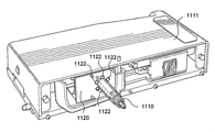
好適な実施形態では、試験ツールアセンブリは、ロードセルカートリッジと称され得るカートリッジ内に提供され得る。カートリッジは、ハウジングを有し得て、試験ツールは、カートリッジハウジングに固定されて、そこから延在している。カートリッジは、有利には、結合部試験装置に取り付け可能な取り外し可能カートリッジであり得て、結合部試験装置から電力を受容するように構成され、また、結合部試験装置と信号を交換するように構成され得る。 In a preferred embodiment, the test tool assembly may be provided in a cartridge, which may be referred to as a load cell cartridge. The cartridge may have a housing and the test tool is secured to and extends from the cartridge housing. The cartridge can advantageously be a removable cartridge that can be attached to the joint test equipment, configured to receive power from the joint test equipment, and to exchange signals with the joint test equipment. Can be configured.
光案内部は、カートリッジに固定されることによって、間接的に試験ツールに固定され得る。光案内部は、カートリッジに恒久的に固定され得るが、有利には、カートリッジに対して取り外し可能に固定可能である。好適には、光案内部は、機械式インターロックによってカートリッジに固定される。例えば、光案内部は、バヨネット適合を用いたり、螺合接続を用いたりして、カートリッジに固定され得る。あるいは、光案内部は、ネジ、ボルトまたはリベット等の機械的固定具を用いて、ロードセルカートリッジに固定され得る。 The optical guide can be indirectly fixed to the test tool by being fixed to the cartridge. The optical guide may be permanently fixed to the cartridge, but advantageously is removable to the cartridge. Preferably, the optical guide is secured to the cartridge by a mechanical interlock. For example, the optical guide may be secured to the cartridge using a bayonet fit or using a screw connection. Alternatively, the optical guide may be secured to the load cell cartridge using mechanical fixtures such as screws, bolts or rivets.
代替的に、あるいは追加的に、光案内部は、試験ツールに直接的に固定され得る。光案内部は、試験ツールに、恒久的にも取り外し可能にも固定され得る。光案内部は、機械式インターロックによって試験ツールに固定され得る。例えば、光案内部は、バヨネット適合を用いたり、螺合接続を用いたりして、試験ツールに固定され得る。あるいは、光案内部は、ネジ、ボルトまたはリベット等の機械的固定具を用いて、試験ツールに固定され得る。 Alternatively or additionally, the light guide may be fixed directly to the test tool. The optical guide may be permanently or removablely secured to the test tool. The optical guide may be secured to the test tool by a mechanical interlock. For example, the optical guide may be secured to the test tool using a bayonet fit or using a screw connection. Alternatively, the light guide may be secured to the test tool using mechanical fixtures such as screws, bolts or rivets.
有利には、光案内部は、工具無しでカートリッジまたは試験ツールから手動で取り外され得る。好適な実施形態では、光案内部は、カートリッジに対して捻られ得て、手動で取り外し可能である。 Advantageously, the optical guide can be manually removed from the cartridge or test tool without tools. In a preferred embodiment, the optical guide can be twisted against the cartridge and can be manually removed.
光案内部は、成型プラスチック材料から形成され得る。有利には、光案内部は、光学用プラスチック材料から形成される。例えば、光案内部は、アクリルから形成され得る。光案内部の1または複数の表面は、高反射面を提供するべく、研磨され得る。代替的に、あるいは追加的に、光案内部の1または複数の表面は、高反射コーティングを有し得る。これは、光案内部からの光の不所望の漏洩を低減し得る。有利には、それを通って光が光案内部を出て試験ツールチップに向かう光案内部の出口面が、研磨され得る。これは、光の不所望の散乱を低減する。 The optical guide may be formed from a molded plastic material. Advantageously, the light guide is made of an optical plastic material. For example, the light guide may be made of acrylic. One or more surfaces of the light guide may be polished to provide a highly reflective surface. Alternatively or additionally, one or more surfaces of the light guide may have a highly reflective coating. This can reduce the undesired leakage of light from the light guide. Advantageously, the exit surface of the light guide through which light exits the light guide and heads towards the test tooltip can be polished. This reduces unwanted scattering of light.
1または複数の光源は、試験ツールに直接的または間接的に固定され得る。好適な実施形態では、1または複数の光源は、試験ツールが固定されているカートリッジに固定される。1または複数の光源は、複数の異なる光源を有し得る。例えば、複数の光源は、異なる色または強度の光源を含み得る。1または複数の光源は、複数の同一の光源を有していてもよい。 One or more light sources may be fixed directly or indirectly to the test tool. In a preferred embodiment, the one or more light sources are fixed to a cartridge to which the test tool is fixed. One or more light sources may have a plurality of different light sources. For example, multiple light sources may include light sources of different colors or intensities. The one or more light sources may have a plurality of the same light sources.
[結合部試験装置のためのカートリッジ]
第2の特徴によれば、本発明は、結合部試験装置のためのカートリッジを提供し得る。好適には、当該カートリッジは、本発明の第1の特徴による試験ツールアセンブリを含んでいる。当該カートリッジは、有利には、結合部試験装置に取り付け可能な取り外し可能カートリッジであり得て、結合部試験装置から電力を受容するように構成され、また、結合部試験装置と信号を交換するように構成され得る。
[Cartridge for joint test equipment]
According to the second feature, the present invention may provide a cartridge for a joint test apparatus. Preferably, the cartridge comprises a test tool assembly according to a first feature of the invention. The cartridge may advantageously be a removable cartridge that can be attached to the joint test equipment, configured to receive power from the joint test equipment, and to exchange signals with the joint test equipment. Can be configured in.
当該カートリッジは、好適には、結合部試験の間に結合部に接触するように構成された試験ツールを有する試験ツールアセンブリを備えている。
当該カートリッジは、更に、試験ツールアセンブリに結合された撓み部と、センサと、を備えている。センサは、撓み部への力の適用時に撓み部の第1端の当該撓み部の第2端に対する変位の測定値を提供するように構成されている。
The cartridge preferably comprises a test tool assembly having a test tool configured to contact the joint during the joint test.
The cartridge further comprises a bend coupled to the test tool assembly and a sensor. The sensor is configured to provide a measured value of the displacement of the first end of the flexed portion with respect to the second end of the flexed portion when a force is applied to the flexed portion.
当該カートリッジは、試験ツールに対して相対的に固定された1または複数の光源と、当該1または複数の光源からの光を試験ツールチップに向けるように構成され試験ツールに対して相対的に固定された光案内部と、を更に備え得る。 The cartridge is configured to direct one or more light sources that are relatively fixed to the test tool and light from the one or more light sources towards the test tooltip and is relatively fixed to the test tool. Further, it may be provided with a light guide unit.
カートリッジ及び光案内部の更なる特徴は、本発明の第1の特徴に関して前述された通りであり得る。 Further features of the cartridge and the optical guide may be as described above with respect to the first feature of the present invention.
本発明の第1の特徴の試験ツールアセンブリと、試験ツールチップを照明するように構成された光案内部と、を有するカートリッジを提供することは、当該カートリッジを例えば20~100μmの小径の結合部を試験するために特に好適とすることができる。
本発明は、試験ツールの顎部の分離の改良された制御と、試験ツールチップの改良された照明と、を提供し得るので、カートリッジは小さな結合部の試験のために正確に制御可能である。
Providing a cartridge comprising a test tool assembly configured to illuminate a test tool tip and a light guide configured to illuminate the test tool tip of the first feature of the invention provides the cartridge with a small diameter coupling of, for example, 20-100 μm. Can be particularly suitable for testing.
The invention can provide improved control of jaw separation of the test tool and improved illumination of the test tooltip so that the cartridge can be precisely controlled for testing small joints. ..
[力を測定する方法]
第3の特徴によれば、本発明は、結合部試験装置内の力を測定する方法を提供し得る。本方法は、第2端に対して移動可能な第1端を有する撓み部を提供する工程と、変位センサを提供する工程と、を備える。本方法は、更に、撓み部の第1端に力を適用する工程と、変位センサを用いて撓み部の第2端に対する撓み部の第1端の変位を測定する工程と、を備える。本方法は、更に、測定された変位を用いて撓み部上の前記力を決定する工程を備える。本方法は、更に、測定された変位と撓み部の既知の剛性とに基づいて撓み部上の力を計算する工程を備え得る。
[How to measure force]
According to the third feature, the present invention may provide a method for measuring a force in a joint test apparatus. The method comprises a step of providing a flexible portion having a first end movable relative to a second end, and a step of providing a displacement sensor. The method further includes a step of applying a force to the first end of the flexible portion and a step of measuring the displacement of the first end of the flexible portion with respect to the second end of the flexible portion using a displacement sensor. The method further comprises a step of determining the force on the flexible portion using the measured displacement. The method may further comprise calculating the force on the flexure based on the measured displacement and the known stiffness of the flexure.
好適には、撓み部、センサ及び結合部試験装置は、本発明の第1の特徴に関して前述された通りである。 Preferably, the flexible portion, sensor and coupling portion test apparatus are as described above with respect to the first feature of the present invention.
撓み部上の力を計算する工程は、有利には、プロセッサまたはコントローラによって実施され得る。 The step of calculating the force on the flexure can advantageously be performed by a processor or controller.
本方法は、撓み部に既知の力を適用して撓み部の剛性を決定する工程と、撓み部の第2端に対する撓み部の第1端の変位を測定する工程と、を更に備え得る。 The method may further include a step of applying a known force to the flexed portion to determine the stiffness of the flexed portion and a step of measuring the displacement of the first end of the flexed portion with respect to the second end of the flexed portion.
[閉鎖力を測定する方法]
第4の特徴によれば、本発明は、結合部試験ツールの顎部の閉鎖力または閉鎖位置を測定する方法を提供し得る。本方法は、第2端に対して移動可能な第1端を有する撓み部を提供する工程と、変位センサを提供する工程と、前記撓み部の前記第1端に取り付けられた駆動機構を提供する工程と、を備える。本方法は、更に、結合部周りに前記試験ツールの顎部を位置決めする工程と、前記駆動機構を用いて前記試験ツールの顎部に閉鎖力を適用し、その結果、前記結合部が前記顎部を介して前記駆動機構へ伝達される反力を適用する工程と、を備える。駆動機構が撓み部の第1端に取り付けられているので、当該反力は、撓み部の第2端に対する撓み部の第1端の変位を生じさせる。
[How to measure the closing force]
According to the fourth feature, the present invention may provide a method for measuring the closing force or the closing position of the jaw of the joint test tool. The method provides a step of providing a flexible portion having a first end movable relative to a second end, a step of providing a displacement sensor, and a drive mechanism attached to the first end of the flexible portion. It is provided with a process to be performed. The method further applies a closing force to the jaw of the test tool using the step of positioning the jaw of the test tool around the joint and the drive mechanism so that the joint is the jaw. A step of applying a reaction force transmitted to the drive mechanism via the unit is provided. Since the drive mechanism is attached to the first end of the flexible portion, the reaction force causes displacement of the first end of the flexible portion with respect to the second end of the flexible portion.
本方法は、更に、変位センサを用いて撓み部の第2端に対する撓み部の第1端の変位を測定する工程と、測定された変位を用いて撓み部上の力を決定する工程と、を備える。 This method further includes a step of measuring the displacement of the first end of the flexible portion with respect to the second end of the flexible portion using a displacement sensor, and a step of determining the force on the flexible portion using the measured displacement. Equipped with.
本方法は、変位と撓み部の既知の剛性とに基づいて撓み部上の力を計算する工程を備え得る。 The method may comprise calculating the force on the flexure based on the displacement and the known stiffness of the flexure.
顎部に閉鎖力を適用する工程は、まず顎部が結合部と接触するように閉鎖力を適用する工程と、顎部が結合部と接触した後で結合部が顎部を介して駆動機構に伝達される反力を適用するように駆動機構を用いて顎部に更なる閉鎖力を適用する工程と、を有し得る。 The steps of applying the closing force to the jaw include the step of applying the closing force so that the jaw comes into contact with the joint, and the drive mechanism of the joint via the jaw after the jaw comes into contact with the joint. There may be a step of applying a further closing force to the jaw using a drive mechanism to apply the reaction force transmitted to.
本方法は、結合部試験を実施する方法であり得るし、結合部試験を実施する方法の一部であり得る。 The method may be a method of performing a junction test or may be part of a method of performing a junction test.
好適には、結合部試験ツール、撓み部、変位センサ及び駆動機構は、本発明の第1の特徴に関して前述された通りである。 Preferably, the joint test tool, flexure, displacement sensor and drive mechanism are as described above with respect to the first feature of the invention.
本方法は、撓み部に既知の力を適用して撓み部の剛性を決定する工程と、撓み部の第2端に対する撓み部の第1端の変位を測定する工程と、を更に備え得る。 The method may further include a step of applying a known force to the flexed portion to determine the stiffness of the flexed portion and a step of measuring the displacement of the first end of the flexed portion with respect to the second end of the flexed portion.
撓み部上の力を計算する工程は、有利には、プロセッサまたはコントローラによって実施され得る。特に好適には、コントローラは、撓み部上の計算された力に基づいて駆動機構を制御するようにプログラムされ得る。例えば、コントローラは、撓み部上の所定の力が測定されるまで閉鎖力を適用するように駆動機構を制御し得る。 The step of calculating the force on the flexure can advantageously be performed by a processor or controller. Particularly preferably, the controller can be programmed to control the drive mechanism based on the calculated force on the flexure. For example, the controller may control the drive mechanism to apply a closing force until a predetermined force on the flexure is measured.
好適には、本方法は、駆動機構距離センサを用いて顎部の分離を測定する工程を更に備え得る。第1の特徴に関して前述された通り、駆動機構距離センサは、駆動機構によって移動された直線方向または角度方向の距離を測定するように構成された、リニアエンコーダまたはロータリエンコーダであり得る。 Preferably, the method may further comprise the step of measuring jaw separation using a drive mechanism distance sensor. As mentioned above with respect to the first feature, the drive mechanism distance sensor can be a linear encoder or a rotary encoder configured to measure a linear or angular distance traveled by the drive mechanism.
好適な実施形態では、本方法は、試験ツールの顎部に所定の閉鎖力を適用するように駆動機構を制御して、その後に顎部の分離を測定する工程を更に備え得る。換言すれば、撓み部の第1端が所定距離だけ変位するまで試験ツールの顎部に閉鎖力が適用され得て、その時点で顎部の分離が駆動機構距離センサによって測定される。 In a preferred embodiment, the method may further comprise controlling the drive mechanism to apply a predetermined closing force to the jaw of the test tool, followed by measuring the jaw separation. In other words, a closing force can be applied to the jaw of the test tool until the first end of the flexure is displaced by a predetermined distance, at which point the jaw separation is measured by the drive mechanism distance sensor.
あるいは、本方法は、顎部が所定の分離状態に到達するまで閉鎖力を適用するように駆動機構を制御して、その後に撓み部上の力を測定して試験ツールによって結合部に作用されている閉鎖力を計算する工程を更に備え得る。これは、結合部が形成されている材料の特性を評価する有用な方法を提供し得る。例えば、予想より小さい閉鎖力が作用して所定の分離状態に顎部が閉鎖される場合、そのことは、結合部が予想よりも小さいか、結合部材料が予想より弱い及び/または低密度である、ということを示し得る。 Alternatively, the method controls the drive mechanism to apply a closing force until the jaw reaches a predetermined separation state, after which the force on the flexure is measured and acted upon by the test tool on the joint. Further steps may be provided to calculate the closing force. This may provide a useful method for assessing the properties of the material in which the joints are formed. For example, if a smaller closing force acts to close the jaw to a given separation state, it means that the joint is smaller than expected, or the joint material is weaker and / or less dense than expected. It can show that there is.
本方法は、試験ツールチップ上に光を案内するために試験ツールに対して固定された光源を用いる工程を更に備え得る。好適には、本方法は、試験対象の結合部周りに顎部を位置決めしている間に一対の顎部を有する試験ツールチップ上に光を案内する工程を更に備え得る。 The method may further comprise the use of a light source fixed to the test tool to guide the light onto the test tooltip. Preferably, the method may further comprise guiding light onto a test tooltip having a pair of jaws while positioning the jaws around the joint to be tested.
本発明のある特徴に関して説明された特徴(特徴的構成)は、本発明の別の特徴にも等しく適用され得る。特に、本発明の第1の特徴に関連して説明された特徴は、本発明の第2の特徴にも適用可能であるし、本発明の第3及び第4の特徴に関連して説明された特徴は、互いに対して適用可能である。 The features described for one feature of the invention (characteristic configuration) may equally apply to another feature of the invention. In particular, the features described in relation to the first feature of the invention are also applicable to the second feature of the invention and are described in connection with the third and fourth features of the invention. The features are applicable to each other.
本発明の実施形態が、添付の図面を参照しながら、単に例示的に、詳細に説明される。 Embodiments of the invention are described in detail, merely exemplary, with reference to the accompanying drawings.
[結合部試験装置]
図1Aは、本発明による結合部試験装置の概略図である。本装置は、試験ツールカートリッジ11に取り付けられた試験ツール10を備えている。試験ツールカートリッジ11は、結合部試験装置12の本体部に取り付けられている。試験ツールの下方において、結合部試験装置は、モータ駆動のステージテーブル13を含んでいる。その上に、試験対象のサンプルないし基板100が取り付けられ得る。
[Joint test equipment]
FIG. 1A is a schematic view of a joint test apparatus according to the present invention. The apparatus includes a
カートリッジ11に取り付けられる試験ツール10は、剪断ツール、押圧ツールまたは引張ツールであり得て、様々な試験を実施するべく切り替えられ得る(交換され得る)。剪断ツールは、例えば、基板から結合部を切り離すように回路盤に水平方向に力を適用するために利用される。押圧ツールは、例えば、基板(基材)上の構成要素上に鉛直方向の圧縮力を適用するために利用される。これらのツールによって適用される力が測定される。引張ツールは、例えば、構成要素とサンプル回路基板との間に取り付けられた導線をフックするために利用される、当該ツールの底部のフックを有し得る。当該導線を基板から引き離すように鉛直方向の力がツールに適用され、当該導線を当該基板から引き離すために要求される力が測定される。好適な剪断ツールの一例が、米国特許第6078387号に開示されている。当該文献の内容は、当該引用によって本明細書に組み込まれる(incorporated by reference)。好適な引張ツールの一例が、米国特許第6310971号に開示されている。当該文献の内容も、当該引用によって本明細書に組み込まれる(incorporated by reference)。
The
図1B乃至図1Eに示されるように、試験ツール10は、典型的には、カートリッジ11の一端にネジ73によって固定された、カンチレバーアーム72、74を有するツール取り付けブラケット70によって、カートリッジ11に取り付けられている。アーム72、74の自由端が、クランプ76を支持している。図1Cに示されるように、ツール10は、クランプネジ78によってクランプ76内にクランプされている。もっとも、試験ツールをカートリッジ取り付け板に取り付けるための任意の好適な手段が、本発明に従うシステム内で利用され得る。
As shown in FIGS. 1B to 1E, the
図1Dは、カートリッジ取り付けプレート21上の保持チャネル71を示している。その中に試験ツールカートリッジ11が摺動して、1または複数のネジ22を用いて固定される。この設計は、ユーザが実施する試験のタイプにとって適当であるように、異なる試験ツールを有する異なる試験ツールカートリッジが結合部試験装置と共に利用されることを許容する。カートリッジ取り付けプレート21は、カートリッジ11のトランスデューサからPCへとデータを伝送するため、試験ツールカートリッジ11上の電気コネクタと結合するデータポート23を含んでいる。データは、例えば、基板からはんだボールを切り離す、あるいは、基板から導線を引き離す、ために必要とされる力を表すデータである。結合部試験装置のための交換可能な試験ツールカートリッジの設計は、従来技術においても周知である。例えば、25ファラデイロード、ラバンスレーンインダストリアルエリア、アイルスベリー、バッキンガムシャー、英国のデージ・ホールディングズ・リミテッドから入手可能なデージ(Dage)4000多機能結合部試験機が参照される。
FIG. 1D shows a holding
カートリッジ11は、ステージテーブル13上の基材100の表面に垂直なz方向に可動である。これは、試験ツール10が鉛直方向に試験対象の基材100に対して位置決めされることを許容する。これにより、試験ツールは、試験中、特定の結合部に接触可能である。基材100の面に平行な方向での試験ツール10とテーブル13との間の相対的なx-y移動が、典型的には、テーブル13を移動することで達成される。x及びy方向でのテーブル13の移動は、例えば前述のデージ4000多機能結合部試験機のような従来技術において周知である、送りネジ及びナット、ボールネジ及びナット、あるいは、好適なベルト駆動機構(不図示)等、を介して当該テーブル13に結合された好適なサーボモータやステッパモータを用いて達成される。
The
制御装置が、図1A及び図1Fに示されている。それは、2つのジョイスティック制御部14、15を有しており、テーブル13の制御動作を可能にしており、また、キーボード16をも有している。ディスプレイ17、試験中の基材100を照明するためのライト18、及び、試験ツール10の正確な位置決めを助けるマイクロスコープも、図示されている。これらの特徴的構成も、例えば前述のデージ4000多機能結合部試験機のような従来技術において周知である。
The control device is shown in FIGS. 1A and 1F. It has two
図1Dは、取り付けプレート21とその本体部25への接続とを図示している。説明されているように、試験ツール(図1Dでは不図示)は、試験中の基材に対して近づく及び離れるように移動可能である必要がある。これは、試験ツール10が取り付けられるカートリッジ取り付けプレート21を、基材に対して近づく及び離れる方向に装置の本体部25に対して移動することで達成される。当該方向は、z軸方向ないし軸方向と呼ばれる。カートリッジ取り付けプレート21は、ネジ75を用いて移動ブロック24に堅固に結合されている。移動ブロック24は、ボールネジ(または送りネジ)及びナット及びナットブロック(不図示)を介して、本体部25に結合されている。それらは、サーボモータまたはステッパモータ26によって駆動される。
FIG. 1D illustrates the
バックラッシュの問題を除去するために、米国特許第9170189号に開示されたようなアンチ(抗)バックラッシュ機構が、含まれ得る。この機構は、図1Dに示されており、好適には、空気圧ピストン27及びシリンダ28を含む。
To eliminate the problem of backlash, an anti-backlash mechanism as disclosed in US Pat. No. 9,170,189 may be included. This mechanism is shown in FIG. 1D and preferably includes a
[ホール効果センサを用いた結合部試験装置]
図2に概略的に図示されているように、第1実施形態の結合部試験装置200は、一対の対向する顎部50を有する引張試験ツール40を用いて引張試験を実施するように構成されている。結合部試験装置は、2つの蛇行形状の撓み部80の第1端に取り付けられたギヤ付きモータ60を備えており、当該撓み部80は互いに上下に配置されていて、鉛直軸線に沿ったモータの移動を許容している。撓み部80の第2端は、表面90に固定されていて、各撓み部80の第1端はその固定の第2端に対して鉛直軸線に沿って移動可能である。モータ60は、両方の撓み部80上に取り付けられており、モータ60の鉛直軸線に沿った移動が同じ距離だけ両方の撓み部80の第1端を変位させる。
[Joint test device using Hall effect sensor]
As schematically illustrated in FIG. 2, the
直径ディスク磁石(diametric disk magnet)110が、撓み部80の第1端に取り付けられている。その磁極は、撓み部80の第1端がそれに沿って移動可能である軸線に対して整列されている。ホール効果センサ(不図示)が、図示の磁石110の前方または後方の鉛直面内で当該磁石110に隣接して位置決めされている。ホール効果センサは、撓み部80の第2端に対して固定されており、すなわち、移動不能である。当該センサは、プロセッサ(不図示)に出力電圧を提供するように構成されており、その大きさは当該センサにおける磁界に従って変化する。
A
モータ60は、リードネジ120を回転するように構成されており、リードネジ120は、モータ60の下方に突出していて、モータ60の移動の鉛直軸線に沿って延びている。リードネジ120には、ナット130が取り付けられており、当該ナット130は、レバー140の第1端によって回転が抑制されている。ナット130は回転が抑制されているため、リードネジ120のモータ60による回転は、ナット130をリードネジ120に沿って鉛直方向に移動させる。
The
レバー140の第2端は、固定回動点145とカム面150とを有しており、カム面150はコレット160の上面に当接するように配置されている。コレット160は、コレット戻しバネ170によって上方に付勢されており、カム面150は、回動点145回りのレバー140の下向き回転によってカムがコレット160にコレット戻しバネ170に対抗して下向きに作用する力を与えるように成形されている。
The second end of the
コレット160は、円筒形状であり、当該コレット160が試験ツールを取り囲むように鉛直配置された試験ツール40回りに同心に配置されている。コレット160の内径は、試験ツールシャフト180の直径よりも大きく、コレット160は、試験ツールシャフト180の鉛直軸線に沿って移動可能である。試験ツールの顎部50は、自然状態では、離れる方向、すなわち外向き方向に付勢されているが、顎部50の幅広部190が面取りされた外面195を有しており、当該面取りされた外面195は顎部50の先端に向かって幅広になっており、幅広部190の直径はコレット160の内径よりも大きい。コレット160の下端は、顎部50の面取りされた外面195と協働するように構成された面取りされた内面210を有しているが、面取りされた内面210の直径は幅広部190よりも小さい。
The
図2に示される全体の装置が、表面90を含めて、基板100に対して移動可能である。好適な実施形態では、例えば、図2に示された装置が、図1A及び図1Fに示されるように、試験ツールカートリッジ11の内部に提供され得る。
The entire device shown in FIG. 2 is mobile with respect to the
[閉鎖力の測定]
使用中、ユーザは、引張試験ツール40が試験対象の結合部の直上になるように装置200を位置決めする前に、試験対象のボンドを保持する基板100をステージ(不図示)上に取り付けることによって、結合部試験を実施し得る。
[Measurement of closing force]
During use, the user can mount the
[第1形態]
第1形態(不図示)では、ナット130がリードネジ120の上端に移動され、カム150は、コレット戻しバネ170に対抗するようには作用しない。コレット戻しバネ170は、従って、完全に伸長されていて、コレット160は、試験ツールシャフト180の上端に向けて付勢されおり、すなわち、試験ツールの幅広部190から離れている。これは、コレット160を試験ツールの幅広部190との接触状態から外れさせ、試験ツールの顎部50は離れるように移動し得る。この形態では、試験ツールの顎部50は、必要に応じて、点検ないし清掃され得る。
[First form]
In the first embodiment (not shown), the
[第2形態]
試験対象の結合部の上方で試験ツール40を下方に移動する前に、本実施形態の装置は、図3に示される第2形態を採用する。そこでは、顎部50が、試験対象の結合部101の直径よりも僅かにのみ大きい分離状態まで、閉鎖される。これは、基板100上の他の結合部と接触することなく、試験ツールの顎部50が試験対象の結合部の面内へと下方に移動されることを許容する。
[Second form]
Prior to moving the
当該第2形態を採用する時の当該システムの主要な力が、図3に示されている。 The main forces of the system when adopting the second form are shown in FIG.
第2形態を採用するために、モータ60は、所定の回転数だけリードネジ120を回転させる。その結果、ナット130は、所定の距離だけリードネジ120に沿って下方に移動する。これは、レバー140の回動点145回りの回転を引き起こし、カム面150が下向き方向の直線駆動力(図3にFDとして示されている)をコレット160に適用する。この駆動力は、コレット戻しバネ170に対抗するように作用して、コレット160を試験ツールシャフト180に沿って下方へと移動させ、コレット160の面取りされた内面210が試験ツール40の面取りされた外面195と係合する。コレット160の内径は試験ツールの幅広部190の直径よりも小さいため、コレット160の面取りされた内面210は、コレット160の下向きの移動を、試験ツールの顎部50上で内向きに作用して顎部50を共に(互いに)近づけるように作用する閉鎖力(図3にFCとして示されている)に変換する。リードネジ120の所定の回転数は、従って、顎部50への所定の閉鎖力の適用に帰結し、顎部50は所定の分離状態まで閉鎖する。
In order to adopt the second mode, the
第2形態の採用時、顎部50は結合部と接触しないため、また、互いに接触しないため、顎部50はそれらの閉鎖に抵抗する何らの有意な力も経験しない(コレット戻しバネ170の力及び顎部50の開放付勢の力は、登場中の他の力と比較して大変に小さいため)。モータ60は、従って、リードネジ120及びナット130がそれらの所定の距離を抵抗無しで移動する間、撓み部80の第1端上で静止状態を維持する。撓み部80が変位しないため、磁石は静止状態を維持し、ホール効果センサ(不図示)の出力は零ボルトを維持する。
When adopting the second embodiment, the
[第3形態]
試験ツール40の先端が試験対象の結合部101と同じ面内に位置決めされた後、
本実施形態の装置は、第3形態を採用する。そこでは、試験ツールの顎部50が結合部に接触して当該結合部を把持する。第3形態は、図4に概略的に図示されており、前述の第2形態と同様の態様で採用される。
[Third form]
After the tip of the
The apparatus of this embodiment adopts the third embodiment. There, the
第3形態に移動するために、試験ツールの顎部50は、リードネジ120を回転させるべくモータ60を制御することによって、結合部周りで閉鎖され、その結果、ナット130は、リードネジ120に沿って下方に移動する。これは、レバー140の回動点145回りの回転を引き起こし、カム面150が下向き方向の直線駆動力(FD)をコレット160に適用する。この駆動力は、コレット戻しバネ170に対抗するように作用して、コレット160を試験ツールシャフト180に沿って更に下方へと移動させ、コレット160の面取りされた内面210が試験ツールの顎部50の幅広部190に対して作用する。コレット160の面取りされた内面と試験ツールの面取りされた外面とが、駆動力を閉鎖力(FC)として顎部50に伝達する。コレット160が試験ツールシャフト180に沿って下方へ移動される程度に応じて、より大きい閉鎖力が顎部50に適用される。
To move to the third form, the
図5は、ナット130がリードネジ120に沿って下方に移動する時にホール効果センサによって測定される力の一例を示している。ナット130がリードネジ120に沿って下方へ移動される距離に応じて、顎部50の分離はより小さくなり、顎部の分離の程度は図5の右方に向かって低減する。
FIG. 5 shows an example of the force measured by the Hall effect sensor as the
図5は、顎部50が結合部に接触する時点500まで、試験ツールの顎部50と結合部との間に力が作用しないで、ホール効果センサが撓み部80上の力を測定しない、ということを示している。
FIG. 5 shows that no force acts between the
試験ツールの顎部50が結合部の直径と等しい顎部の分離状態まで閉鎖されると、顎部は結合部と接触して当該結合部を把持し始める。しかしながら、顎部50が結合部と接触した状態では、更なる閉鎖力の適用は、結合部自身からの抵抗に会う。顎部による締め付けに対する当該抵抗は、結合部と顎部50との間に反力(図4にFRとして示されている)を生成する。当該反力は、顎部上で、閉鎖力とは反対方向の外向きに作用する。この反力は、コレット160を介して逆方向に伝達され、当該反力は、コレット戻しバネ170と同一方向に作用し、カム150及びレバー140の更なる回転に抵抗する。
When the
これは、モータ60がリードネジ120を回転し続ける間、反力がナット130の更なる移動に抵抗する、ということを意味する。リードネジ120(実際上は静止状態)に沿って下方に移動しようとするナット130を単に押し付けるというより、リードネジ120の更なる回転は、従って、ナット130を介してリードネジ120自身を上方に変位させ始める。このリードネジ120の上方への移動が、モータ60を変位させ、撓み部80の第1端が曲げられる。
This means that the reaction force resists further movement of the
撓み部80の第1端の曲がりは、図4に示すように、ホール効果センサに対して磁石110を変位させる。この変位は、ホール効果センサ(不図示)が、磁石が変位した距離に正比例する磁界の変化を検出することを意味する。磁石の変位は撓み部80の第1端の変位に等しいため、ホール効果センサは、撓み部80の第2端に対する第1端の変位の測定値をプロセッサ(不図示)に提供する。
The bending of the first end of the bending
撓み部80の剛性は既知であるので、プロセッサは、測定された変位に基づいて撓み部上の力(FR)を計算可能である。 Since the stiffness of the flexure is known, the processor can calculate the force ( FR ) on the flexure based on the measured displacement.
図5に示すように、試験ツールの顎部50が結合部101に接触した後、反力(FR)はコレット160及びレバー140を介してモータ60に伝達され、撓み部80が上方に曲げられる。この撓み部80の変位がホール効果センサによって検出され、撓み部上の反力(FR)が撓み部80の既知の剛性に基づいてプロセッサによって計算される。
図5に示すように、撓み部80上の反力(FR)は、顎部50間の距離が低減するにつれて線形に増大する。レバー140及びコレット160の力増幅効果のため、撓み部80上で経験される反力の大きさは、顎部50で経験される閉鎖力よりも小さいことが知られている。試験ツールによって結合部に適用される閉鎖力(FC)は、従って、レバー140の当該効果及びシステム内の摩擦力を考慮してプロセッサによって計算され得る。本装置の撓み部80及びホール効果センサは、従って、顎部50と試験対象の結合部との間に適用される閉鎖力を測定するために利用され得る。
As shown in FIG. 5, after the
As shown in FIG. 5, the reaction force ( FR ) on the
図5に示されるように、閉鎖力(FC)もまた、顎部50間の距離が低減するにつれて、反力(FR)と共に線形に増大する。
As shown in FIG. 5, the closing force ( FC ) also increases linearly with the reaction force ( FR ) as the distance between the
プロセッサにフィードバック信号を提供することによって、ホール効果センサからの測定値は、装置を制御するために利用され得て、従って、結合部試験の間に結合部に適用される閉鎖力を制御するために利用され得る。これは、有利には、プロセッサが、各試験中に結合部に所望の閉鎖力を一貫して適用する、あるいは、顎部を所定距離に閉鎖して結果としての閉鎖力を測定する、ことを許容する。 By providing a feedback signal to the processor, the measurements from the Hall effect sensor can be utilized to control the device and thus to control the closure force applied to the junction during the junction test. Can be used for. This is advantageous because the processor consistently applies the desired closure force to the joint during each test, or closes the jaw to a predetermined distance and measures the resulting closure force. Tolerate.
[ホール効果センサ]
図6Aは、本発明における利用にとって好適なホール効果センサ220及び直径方向ディスク磁石110の第1実施形態を示している。発明の概要の項で前述されたように、ホール効果センサは出力電圧を提供し、その大きさはセンサにおいて経験される磁界に依存する。ホール効果センサに対する磁石の変位は、従って、センサにおける磁界の変化をもたらし、それがホール効果センサからの電圧出力信号の変化として図示されている。
[Hall effect sensor]
FIG. 6A shows a first embodiment of a
ホール効果センサは、磁石の移動面の外側で、磁石に隣接して着座するように配置されている。ホール効果センサの検出面230は、磁石に面するように配置されており、磁石のセンサに対する変位が、検出面230において経験される磁界の変化を引き起こす。磁石のN極とS極は、磁石の移動軸(矢印で示されている)に対して整列されており、磁石が当該軸に沿って移動する時にセンサによって経験される磁界の変化を最大化する。
The Hall effect sensor is located outside the moving surface of the magnet so as to sit adjacent to the magnet. The
図6Bに図示されているように、第2実施形態では、2つのホール効果センサ220が利用されている。両センサは、磁石110の両側で互いに反対向きに配置されている。
2つのセンサの出力を結合することによって、出力信号の大きさが増大され、装置の感度を増大させる。
As illustrated in FIG. 6B, two
By combining the outputs of the two sensors, the magnitude of the output signal is increased and the sensitivity of the device is increased.
図6Cに図示されているように、図6Aのシングルセンサからの出力電圧信号250と、図6Bのデュアルセンサからの出力電圧信号300とは、例えば2mmまで(図6Cでは0~1.8mm)の短い距離に亘っての磁石の変位距離に関して、高い線形の相関を示し(高いR2値によって示されている)、小さい変位が高精度に測定されることを許容する。シングルのホール効果センサの出力でさえ、mm毎に数ボルトの変化を示し、弱い電圧信号を増幅する必要無しで容易な測定が可能である。この精度と、出力信号の大きさとが、本発明における使用にとって、ホール効果センサを非常に好適なものとする。
As shown in FIG. 6C, the
ホール効果センサ220は、磁石110と当該センサとの間での永久的なオフセットを補償するべく較正され得るが、図6A及び図6Bに示された好適な実施形態によれば、磁石が零変位である時、磁石の中心がホール効果センサの中心と整列されている。この形態では、零変位において、磁石のセンサに対する対称性のため、ホール効果センサは磁石の移動軸に沿って零の磁界を経験する。
The
いずれの方向でも、当該移動軸に沿った磁石の変位が磁界を変化させて、ホール効果センサからの零でない出力電圧をもたらす。 In either direction, the displacement of the magnet along the moving axis changes the magnetic field, resulting in a non-zero output voltage from the Hall effect sensor.
[装置の具体例]
図7は、本発明の結合部試験装置の好適な実施形態350を図示している。当該装置350は、カートリッジ11(図7では不図示)の内部に収容されるように構成されている。図7の装置350は、引張試験ツール400と結合部(不図示)との間で作用される閉鎖力を測定するように構成されている。
[Specific example of device]
FIG. 7 illustrates a
当該装置350は、一体部品である金属骨格360を備えており、2つの折り畳まれた形態のビームによる撓み部380の共有された第2端370が、それに堅固に取り付けられている。当該撓み部380の第1端390は、共に、フレーム410によってギヤ付き電気モータ405に堅固に取り付けられている。フレーム410とモータ405とは、共に結合されており、金属骨格360に対して移動可能であり、モータ405の変位が撓み部380の第2端370に対する第1端390の変位をもたらす。撓み部380が互いに隣接している形態であるため、撓み部380は、試験ツール400の軸に関して整列された単一の軸(図7に矢印で示されている)に沿ってのみ変位され得る。フレーム410には、直径方向磁化ディスク磁石415が取り付けており、そのN極とS極とが撓み部380の移動軸に対して整列されている。磁石415は、フレーム410に堅固に取り付けられており、フレーム410の変位が磁石415を変位させる。
The
2つのホール効果センサ425が印刷回路基板435上に取り付けられており、センサの出力電圧信号が印刷回路基板に供給される。印刷回路基板435は、フレーム410から分離しており、金属骨格360及び撓み部380の第2端370に対して所定位置に固定されている。ホール効果センサ425は、磁石415の両側に互いに対向するように配置されており、磁石415の当該センサ425間での移動がホール効果センサ425によって検出される磁界の変化を引き起こす。これが、センサの電圧出力信号の変化に帰結する。
Two
リードネジ420が、モータ405によって回転可能であり、モータ405から突出しており、試験ツール400と同じ軸に沿って配置されている。ナット430が、リードネジ420上に取り付けられている。ナット430の一部が、フレーム410に摺動可能に係合しており、リードネジ420のモータ405による回転が、リードネジ420の回転方向によって決定される方向にナット430をリードネジ420に沿って摺動させる。ナット320は、レバー440の第1端に係合されており、レバー440の第2端は、回動点445と回転可能に係合されている。回動点445は、金属骨格360に対して固定されている。レバー440の第2端は、カム面450を有しており、当該カム面450は、スリーブ460の上面に当接するように配置されている。
The
スリーブ460は、円筒状であり、試験ツール400を取り囲んでいる。スリーブ460は、試験ツール400の周りに配置された円筒状のセラミック製のカラー470を有し、スリーブ460の全体が、試験ツール400に対して、試験ツール400の軸に沿って、摺動移動可能である。スリーブ460は、撓み部380に取り付けられておらず、スリーブ460の移動は、撓み部380を直接的に曲げない。
The
引張試験ツール400は、回転可能であるが、骨格360に対して所定位置に固定されている。試験ツール400の外面は、セラミック製のカラー470と試験ツール400の先端との間に配置された幅広部を有しており、試験ツール400の顎部が、自然状態では開放位置に付勢されている。セラミック製のカラー470の直径は、試験ツール400の幅広部の直径よりも小さく、スリーブ460及びカラー470の試験ツール400の先端に向かう移動が、顎部を互いに近づける閉鎖力を生成する。
The
装置350は、引張試験ツール400の顎部によって結合部に適用される閉鎖力を測定するために利用可能である。図7の装置350の動作は、図2乃至図4に関して説明された通りであり、スリーブ460及びセラミック製のカラー470が、図2乃至図4に関して説明されたコレットの役割を担う。
The
図7の装置350は、選択的に、より大きな第2撓み部の第1端に取り付けられ得る。骨格360、従って試験ツール400は、第2撓み部に対して静止状態に固定され、試験ツール400と結合部との間に試験力の適用は、第2撓み部の第1端の変位をもたらす。第2磁石が、第2撓み部の移動可能な第1端に取り付けられ得て、第2ホール効果センサが、第2撓み部の固定された第2端に対して固定され得る。これにより、第2ホール効果センサによる第2磁石の変位の測定が、試験ツール400と試験対象の結合部との間に適用される試験力の測定のために利用され得る。
The
図7に図示された全体の装置は、好適には、図1A及び図1Fに図示された試験ツールカートリッジ11の内部に提供される。
The entire device illustrated in FIG. 7 is preferably provided inside the
本発明の一実施形態では、結合部試験の照明、視覚的検査のための照明、及び、ビデオ記録ないし写真記録のための照明、を改善するために、複数の発光ダイオード(LED)がカートリッジ内に設けられ、試験ツールの周囲に位置決めされている。図8Aは、本発明の一実施形態によるカートリッジ1111を図示している。当該カートリッジは、図1B乃至図1Fを参照して説明された態様でカートリッジ取り付けプレートに固定された引張試験ツール1110を有している。当該試験ツール1110は、略円筒形状を有している。プリント回路基板(PCB)1200が、カートリッジに固定されて、試験ツール1110の周囲に延在している。当該回路基板上に、複数のLED1122が取り付けられている。プリント基板1120の図示のため、カートリッジのハウジングの一部の図示が、図8Aでは省略されている。複数のLEDは、試験ツールの周囲でリング形状を形成している。複数のLEDは、可変の明るさを有するように制御可能であり、異なる色を有し得る。
In one embodiment of the invention, a plurality of light emitting diodes (LEDs) are contained within the cartridge to improve lighting for joint testing, lighting for visual inspection, and lighting for video or photographic recording. And is positioned around the test tool. FIG. 8A illustrates a
LEDからの光をより効率良く利用するために、また、試験ツールが試験箇所に影をもたらすことを防止するために、光案内部が試験ツールの周囲に固定されて、LEDによって発光される光を捕捉して、それを試験ツールの先端(チップ)の周囲の試験箇所に焦点合わせする。 In order to use the light from the LED more efficiently and to prevent the test tool from casting shadows on the test site, a light guide is fixed around the test tool and the light emitted by the LED is emitted. And focus it on the test site around the tip of the test tool.
図8Bは、図8Aのカートリッジを図示している。ハウジングの底部プレート1124がPCB1120の上方に固定されている。管状の光案内部1130がカートリッジに取り付けられている。光案内部1130は、LED1122に隣接して位置する基端と、試験ツールチップに近い先端と、を有している。光案内部1130は、バヨネット結合を用いてカートリッジハウジングの底部プレート1124に固定される。それは、試験ツールの上方に簡単に載置され得て、所定位置にそれを係止するべく手動で回転され得る。光案内部は、反対の操作を実施することによって、カートリッジから取り外され得る。図示の実施形態では、光案内部は、側壁に設けられた一対のスロット1132を有しており、カートリッジから光案内部を取り外す必要無しで、光案内部内で工具が試験ツールと係合することを許容している。これは、幾つかのタイプの試験ツールにとって望ましいが、他のタイプの試験ツールにとっては必要でない。
FIG. 8B illustrates the cartridge of FIG. 8A. The
LED1122から発せられる光は、光案内部1130の基端に入り、全内反射によって光案内部の側壁を通って出ることが防止される。光案内部の側壁には、高反射コーティングが設けられ得て、最小の光損失を保証し得る。光案内部は、その先端において出口面1136を有しており、それを通って光が出る。光案内部は、試験ツールチップに光を案内するべく、その先端において先細状となっている。
The light emitted from the
LED1122は、調整可能な明るさを有し得る。これは、試験対象の異なるサンプルが異なる明るさでの照明を要求し得るので、有益である。このような実施形態では、LEDの明るさは、DC電圧のアナログ制御を用いて制御され得る。これは、LEDを制御するための、より一般的な電圧のデジタル変調とは異なる。なぜなら、変調は、試験ツールの適切な動作と干渉し得るノイズを生成してしまうからである。LEDは、また、試験対象の異なるサンプルに適合するべく利用され得る、異なる色を発光するLEDを含み得る。
The
図9A及び図9Bは、試験ツールから取り外された光案内部をより詳細に図示している。図9Aは、光案内部1130の断面図である。光案内部は、全体的に管状であり、アクリルから形成されている。ガラスや他の光学用プラスチックのような他の光学材料も、利用され得る。光案内部は、中央部1135において、約4mmの壁厚を有しているが、カートリッジと係合する基端1137においてはより厚く、光が光案内部を出る先端1139においてはより薄い。光案内部は、試験ツールチップに向けて光を案内するべく、先端において先細状である。光案内部は、先端において内側鏡面1134を有しており、それは、本例においては、光案内部の長手方向軸に対して13°の角度である。
9A and 9B show the optical guide removed from the test tool in more detail. FIG. 9A is a cross-sectional view of the
破線1144は、LEDからの光の経路を示しており、基端面1146を通って入って、光案内部を通過し、出口面1136を通って光案内部を出て、試験ツールチップ1142の先端に向かう。一点鎖線1140は、光案内部1130の長手方向軸を示している。
The
図9Bは、図9Aの光案内部の斜視図であり、バヨネット嵌合特徴部1150を図示している。光案内部の基端は、一対のウィング1150を有しており、それらは光案内部の本体部から径方向に延びている。それらウィング1150は、カートリッジハウジングの底部プレート1124の対応するスロット内に受容され、当該底部プレートの後面に係合するべく回転される。面1152が、当該底部プレートの前面と係合する。
9B is a perspective view of the optical guide portion of FIG. 9A, and illustrates the bayonet
一対のスロット1132が、光案内部の側壁内に設けられており、工具を用いての光案内部の容易な把持を許容している。
A pair of
前述のような光案内部を設けることは、効率良く制御可能な態様で、試験箇所をより良好に証明することに帰結する。照明システムは、試験ツールの動作と干渉しないし、結合部試験装置の他の要素、例えばマイクロスコープの視野、と干渉することもない。試験ツールが試験箇所に影を投影することもない。同様に、試験箇所に近接した他の構成要素によって投影される影も、光案内部を用いることによって最小化される。光案内部は、低価格で製造され得て、必要に応じてユーザによって簡単に装着及び取り外しができる。光案内部は、試験ツールの保護をも提供し得る。 Providing the optical guide as described above results in better proof of the test site in an efficient and controllable manner. The lighting system does not interfere with the operation of the test tool and does not interfere with other elements of the joint tester, such as the field of view of the microscope. The test tool also does not cast shadows on the test area. Similarly, shadows cast by other components in close proximity to the test site are also minimized by using light guides. The optical guide can be manufactured at a low price and can be easily attached and detached by the user as needed. The optical guide may also provide protection for the test tool.
本発明のカートリッジ及び試験ツールアセンブリは、従って、試験ツールチップと試験対象の結合部との良好な照明を提供し、試験ツールの顎部が所望の分離状態に開放ないし閉鎖されることを許容する。これは、有利なことに、特に小径の試験対象の結合部の時に、試験前に結合部の周りにより正確に試験ツールを位置決め可能であるため、試験ツールの顎部の改良された制御を許容する。 The cartridge and test tool assembly of the present invention thus provide good illumination between the test tool tip and the joint to be tested and allow the jaw of the test tool to be opened or closed to the desired separation. .. This advantageously allows for improved control of the jaws of the test tool, as it allows the test tool to be more accurately positioned around the joint prior to testing, especially at the joints of small diameter test objects. do.
Claims (31)
前記試験ツールに結合された撓み部と、
閉鎖部材と、
前記閉鎖部材に駆動力を適用するように構成された駆動機構と、
変位センサと、
検出可能部材と、
前記変位センサからの変位信号を受容し、当該変位信号を用いて前記撓み部の力を決定するように構成されたプロセッサと、
を備えた結合部試験装置であって、
当該結合部試験装置は、前記一対の対向する顎部を有する前記試験ツールを用いて引張試験を実施するように構成されており、
前記閉鎖部材は、前記基板の面に平行な方向に沿って前記顎部を閉鎖するように、前記顎部に閉鎖力を適用し、
前記検出可能部材と前記変位センサとの内の一方が、前記撓み部の第1端に固定されており、
前記検出可能部材と前記変位センサとの内の他方が、前記撓み部の第2端に固定されており、
前記変位センサは、当該変位センサと前記検出可能部材との間の変位を検出するように構成されており、
前記変位センサは、前記撓み部への力の適用時に当該撓み部の前記第1端の当該撓み部の前記第2端に対する変位の測定値を提供する
ことを特徴とする結合部試験装置。 A test tool having a test tooltip configured to contact a joint on a substrate during a joint test and having a pair of opposing jaws urged in an open form.
The flexible part coupled to the test tool and
Closing member and
A drive mechanism configured to apply a drive force to the closing member,
Displacement sensor and
Detectable member and
A processor configured to receive a displacement signal from the displacement sensor and use the displacement signal to determine the force of the flexure.
It is a joint test device equipped with
The joint test apparatus is configured to perform a tensile test using the test tool having the pair of opposing jaws.
The closing member applies a closing force to the jaw so as to close the jaw along a direction parallel to the plane of the substrate.
One of the detectable member and the displacement sensor is fixed to the first end of the flexible portion.
The other of the detectable member and the displacement sensor is fixed to the second end of the flexible portion.
The displacement sensor is configured to detect the displacement between the displacement sensor and the detectable member.
The displacement sensor is a coupling test apparatus comprising providing a measured value of displacement of the first end of the flexible portion with respect to the second end of the flexible portion when a force is applied to the flexible portion.
ことを特徴とする請求項1に記載の結合部試験装置。 The coupling portion according to claim 1, wherein the processor is further configured to determine the force of the flexible portion using the displacement signal together with the previously known rigidity of the flexible portion. Test equipment.
ことを特徴とする請求項1または2に記載の結合部試験装置。 The coupling portion test apparatus according to claim 1 or 2, wherein the displacement sensor is further configured to output a displacement signal proportional to the displacement of the first end of the flexible portion.
前記磁石部と前記変位センサとの内の一方が、前記撓み部の前記第1端に固定されており、
前記変位センサは、磁界の変化を検出するように構成されており、
前記撓み部の前記第1端の前記第2端に対する変位は、前記磁石部を前記変位センサに対して移動させ、前記変位センサが磁界の変化を検出する
ことを特徴とする請求項1または2に記載の結合部試験装置。 The detectable member has a magnet portion and has a magnet portion.
One of the magnet portion and the displacement sensor is fixed to the first end of the flexible portion.
The displacement sensor is configured to detect changes in the magnetic field.
The displacement of the first end of the flexible portion with respect to the second end is characterized in that the magnet portion is moved with respect to the displacement sensor, and the displacement sensor detects a change in a magnetic field. The joint test apparatus according to.
ことを特徴とする請求項1または2に記載の結合部試験装置。 The joint test apparatus according to claim 1 or 2, wherein the displacement sensor is a Hall effect sensor.
ことを特徴とする請求項1または2に記載の結合部試験装置。 The joint test apparatus according to claim 1 or 2, wherein the displacement sensor is an optical displacement sensor.
前記結合部による前記試験ツールへの試験力の適用が、前記撓み部の前記第1端の相対変位をもたらす
ことを特徴とする請求項1または2に記載の結合部試験装置。 The test tool is fixed to the first end of the flexible portion.
The joint test apparatus according to claim 1 or 2, wherein application of the test force to the test tool by the joint results in a relative displacement of the first end of the flexible portion.
ことを特徴とする請求項1または2に記載の結合部試験装置。 The claim comprises a drive mechanism distance sensor configured to measure the distance traveled by the drive mechanism while applying the drive force to the closure member. Item 2. The joint test apparatus according to Item 1.
ことを特徴とする請求項1に記載の結合部試験装置。 The drive mechanism is configured such that when the jaw portion of the test tool grips the joint portion, the application of the driving force causes the first end of the flexible portion to be displaced with respect to the second end. The joint test apparatus according to claim 1.
前記撓み部の前記第1端は、前記試験ツールに対して移動可能であり、
前記駆動機構は、前記試験ツールの前記顎部が前記結合部を把持する時、前記駆動力の適用が前記閉鎖部材と前記駆動機構との間で反力を生成し、当該反力が前記撓み部の前記第1端を前記第2端に対して変位させる、というように構成されている
ことを特徴とする請求項1に記載の結合部試験装置。 The drive mechanism is attached to the first end of the flexible portion.
The first end of the flexible portion is movable with respect to the test tool.
In the drive mechanism, when the jaw portion of the test tool grips the joint portion, the application of the drive force generates a reaction force between the closing member and the drive mechanism, and the reaction force causes the deflection. The joint portion test apparatus according to claim 1, wherein the first end of the portion is displaced with respect to the second end.
前記スリーブは、前記顎部に対して軸方向に移動可能であって、前記顎部に対する前記スリーブの移動が前記顎部に前記閉鎖力を適用する、というように前記顎部と係合するように構成されている
ことを特徴とする請求項1に記載の結合部試験装置。 The closing member has a sleeve arranged so as to surround at least a part of the jaw.
The sleeve is axially movable with respect to the jaw so that the movement of the sleeve with respect to the jaw applies the closing force to the jaw and thus engages the jaw. The joint test apparatus according to claim 1, wherein the joint test apparatus is configured in the above-mentioned.
ことを特徴とする請求項11に記載の結合部試験装置。 11. The sleeve comprises a frictional material, wherein the frictional force between the sleeve and the chin is at least 10 times smaller than the closing force on the chin during use. The joint test device described.
前記駆動機構は、前記スリーブを前記顎部に向けて移動する方向に前記駆動力を適用するように構成されている
ことを特徴とする請求項11に記載の結合部試験装置。 The sleeve is urged away from the chin and
The coupling portion test apparatus according to claim 11, wherein the driving mechanism is configured to apply the driving force in a direction in which the sleeve is moved toward the jaw portion.
前記モータは、前記リードネジを回転するように構成されており、
前記ナットは、前記モータによる前記リードネジの回転時に、前記リードネジに対して移動可能であり、
前記駆動機構は、前記リードネジに対する前記ナットの移動が前記駆動力を前記閉鎖部材に適用する、というように構成されている
ことを特徴とする請求項1に記載の結合部試験装置。 The drive mechanism comprises a motor, a lead screw, and a nut mounted on the lead screw.
The motor is configured to rotate the lead screw.
The nut is movable with respect to the lead screw when the lead screw is rotated by the motor.
The coupling portion test apparatus according to claim 1, wherein the drive mechanism is configured such that the movement of the nut with respect to the lead screw applies the driving force to the closing member.
前記ナットは、前記レバーの第1端と移動可能に係合されており、
前記レバーは、前記第1端とは反対側の第2端回りに回動可能であり、使用中、前記リードネジに沿った前記ナットの移動が前記レバーの前記第1端を移動させて、前記レバーが前記第2端回りに回動する
ことを特徴とする請求項14に記載の結合部試験装置。 The drive mechanism further comprises a lever.
The nut is movably engaged with the first end of the lever.
The lever is rotatable around a second end opposite to the first end, and the movement of the nut along the lead screw causes the first end of the lever to move during use. The joint test apparatus according to claim 14, wherein the lever rotates around the second end.
前記カム機構は、前記第2端回りの前記レバーの回動によって、使用中、カムが前記閉鎖部材に前記駆動力を適用する、というように構成されている
ことを特徴とする請求項15に記載の結合部試験装置。 The lever has a cam mechanism arranged to abut the closing member.
15. The cam mechanism is characterized in that, by rotating the lever around the second end, the cam applies the driving force to the closing member during use. The joint test device described.
前記試験ツール、前記変位センサ、及び、前記第1撓み部が、第2撓み部の第1端に取り付けられており、
前記第2撓み部の前記第1端は、当該第2撓み部の第2端に対して移動可能であり、
当該結合部試験装置は、更に、第2センサを有しており、
前記第2センサは、前記試験ツールによる前記結合部への試験力の適用時に前記第2撓み部の前記第1端の前記第2撓み部の前記第2端に対する変位を測定するように構成されている
ことを特徴とする請求項1に記載の結合部試験装置。 The flexible portion is a first flexible portion, and is
The test tool, the displacement sensor, and the first bending portion are attached to the first end of the second bending portion.
The first end of the second flexible portion is movable with respect to the second end of the second flexible portion.
The joint test device further has a second sensor.
The second sensor is configured to measure the displacement of the first end of the second bend with respect to the second end of the second bend when the test force is applied to the joint by the test tool. The joint test apparatus according to claim 1.
ことを特徴とする請求項17に記載の結合部試験装置。 17. The coupling portion testing apparatus according to claim 17, wherein the test tool, the first bending portion, and the displacement sensor are configured to measure a closing force on the jaw portion.
ことを特徴とする請求項1に記載の結合部試験装置。 The coupling test apparatus further comprises one or more light sources that are relatively fixed relative to the test tool and is configured to direct light from the one or more light sources to the test tooltip. The joint test apparatus according to claim 1.
ことを特徴とする請求項1に記載の結合部試験装置。 When the jaw portion is in contact with the joint portion, the driving force is proportional to the closing force of the jaw portion at the joint portion, and the first end of the flexible portion is the said portion of the flexible portion. The joint test apparatus according to claim 1, wherein the joint portion is displaced with respect to the second end.
結合部試験の間に基板上の結合部に接触するように構成された試験ツールチップを有し、開放形態に付勢された一対の対向する顎部を有している、試験ツールと、
前記試験ツールに結合された撓み部と、
閉鎖部材と、
前記閉鎖部材に駆動力を適用するように構成された駆動機構と、
変位センサと、
検出可能部材と、
を備え、
当該カートリッジは、前記一対の対向する顎部を有する前記試験ツールを用いて引張試験を実施するように構成されており、
前記閉鎖部材は、前記基板の面に平行な方向に沿って前記顎部を閉鎖するように、前記顎部に閉鎖力を適用し、
前記検出可能部材と前記変位センサとの内の一方が、前記撓み部の第1端に固定されており、
前記検出可能部材と前記変位センサとの内の他方が、前記撓み部の第2端に固定されており、
前記変位センサは、当該変位センサと前記検出可能部材との間の変位を検出するように構成されており、
前記変位センサは、前記撓み部への力の適用時に当該撓み部の前記第1端の当該撓み部の前記第2端に対する変位の測定値を提供する
ことを特徴とするカートリッジ。 Cartridge for joint test equipment
A test tool having a test tooltip configured to contact the joint on the substrate during the joint test and having a pair of opposing jaws urged in an open form.
The flexible part coupled to the test tool and
Closing member and
A drive mechanism configured to apply a drive force to the closing member,
Displacement sensor and
Detectable member and
Equipped with
The cartridge is configured to perform a tensile test using the test tool having the pair of opposed jaws.
The closing member applies a closing force to the jaw so as to close the jaw along a direction parallel to the plane of the substrate.
One of the detectable member and the displacement sensor is fixed to the first end of the flexible portion.
The other of the detectable member and the displacement sensor is fixed to the second end of the flexible portion.
The displacement sensor is configured to detect the displacement between the displacement sensor and the detectable member.
The displacement sensor is a cartridge characterized in that when a force is applied to the flexible portion, the displacement of the first end of the flexible portion is measured with respect to the second end of the flexible portion.
前記試験ツールに対して相対的に固定された1または複数の光源と、
当該1または複数の光源からの光を前記試験ツールチップに向けるように構成され前記試験ツールに対して相対的に固定された光案内部と、
を備えることを特徴とする請求項21に記載のカートリッジ。 The cartridge is further
With one or more light sources fixed relative to the test tool,
An optical guide that is configured to direct light from the one or more light sources towards the test tooltip and is relatively fixed relative to the test tool.
21. The cartridge according to claim 21.
ことを特徴とする請求項21に記載のカートリッジ。 When the jaw portion is in contact with the joint portion, the driving force is proportional to the closing force of the jaw portion at the joint portion, and the first end of the flexible portion is the said portion of the flexible portion. 21. The cartridge according to claim 21, wherein the cartridge is displaced with respect to a second end.
結合部試験の間に基板上の結合部に接触するように構成された試験ツールチップと、開放形態に付勢された一対の対向する顎部と、を有している試験ツール、を提供する工程と、
第2端に対して移動可能な第1端を有する撓み部を提供する工程と、
閉鎖部材を提供する工程と、
前記閉鎖部材に駆動力を適用するように構成された駆動機構を提供する工程と、
変位センサ及び検出可能部材を提供する工程と、
を備え、
前記結合部試験装置は、前記一対の対向する顎部を有する前記試験ツールを用いて引張試験を実施するように構成されており、
前記閉鎖部材は、前記基板の面に平行な方向に沿って前記顎部を閉鎖するように、前記顎部に閉鎖力を適用し、
前記検出可能部材と前記変位センサとの内の一方が、前記撓み部の前記第1端に固定されており、
前記検出可能部材と前記変位センサとの内の他方が、前記撓み部の前記第2端に固定されており、
前記変位センサは、当該変位センサと前記検出可能部材との間の変位を検出するように構成されており、
当該方法は、更に、
前記撓み部の前記第1端に反力を適用する工程と、
前記変位センサを用いて、前記撓み部の前記第1端の前記撓み部の前記第2端に対する変位を測定する工程と、
前記測定された変位を用いて、前記撓み部上の反力を決定する工程と、
を備えた方法。 It is a method of measuring the force in the joint test device.
Provided is a test tool having a test tooltip configured to contact a joint on a substrate during a joint test and a pair of opposing jaws urged in an open form. Process and
A step of providing a flexible portion having a first end that is movable with respect to the second end, and
The process of providing the closing member and
A step of providing a drive mechanism configured to apply a drive force to the closing member, and
A process for providing a displacement sensor and a detectable member, and
Equipped with
The joint test apparatus is configured to perform a tensile test using the test tool having the pair of opposing jaws.
The closing member applies a closing force to the jaw so as to close the jaw along a direction parallel to the plane of the substrate.
One of the detectable member and the displacement sensor is fixed to the first end of the flexible portion.
The other of the detectable member and the displacement sensor is fixed to the second end of the flexible portion.
The displacement sensor is configured to detect the displacement between the displacement sensor and the detectable member.
The method further
A step of applying a reaction force to the first end of the flexible portion, and
Using the displacement sensor, the step of measuring the displacement of the first end of the flexible portion with respect to the second end of the flexible portion, and the step of measuring the displacement of the flexible portion with respect to the second end.
The step of determining the reaction force on the flexible portion using the measured displacement, and
A method equipped with.
ことを特徴とする請求項24に記載の方法。 24. The step of determining the reaction force includes the step of calculating the reaction force on the flexible portion based on the measured displacement and the known rigidity of the flexible portion. The method described in.
結合部試験の間に基板上の結合部に接触するように構成された試験ツールチップと、開放形態に付勢された前記一対の対向する顎部と、を有している前記結合部試験ツール、を提供する工程と、
第2端に対して移動可能な第1端を有する撓み部を提供する工程と、
閉鎖部材を提供する工程と、
変位センサ及び検出可能部材を提供する工程と、
前記撓み部の前記第1端に取り付けられ、前記閉鎖部材に駆動力を適用するように構成された駆動機構を提供する工程と、
を備え、
前記結合部試験装置は、前記一対の対向する顎部を有する前記結合部試験ツールを用いて引張試験を実施するように構成されており、
前記検出可能部材と前記変位センサとの内の一方が、前記撓み部の前記第1端に固定されており、
前記検出可能部材と前記変位センサとの内の他方が、前記撓み部の前記第2端に固定されており、
前記変位センサは、当該変位センサと前記検出可能部材との間の変位を検出するように構成されており、
前記閉鎖部材は、前記基板の面に平行な方向に沿って前記顎部を閉鎖するように、前記顎部に閉鎖力を適用し、
当該方法は、更に、
前記結合部周りに前記結合部試験ツールの前記顎部を位置決めする工程と、
前記駆動機構を用いて前記結合部試験ツールの前記顎部に前記閉鎖力を適用し、その結果、前記結合部が前記顎部を介して前記駆動機構へ反力を適用し、当該反力が前記撓み部の前記第2端に対する前記撓み部の前記第1端の変位を生じさせる工程と、
前記変位センサを用いて前記撓み部の前記第2端に対する前記撓み部の前記第1端の変位を測定する工程と、
測定された変位を用いて前記撓み部上の前記反力を計算する工程と、
を備えたことを特徴とする方法。 A method of measuring the closing force on a pair of opposing jaws of a joint test tool in a joint test device.
The joint test tool having a test tooltip configured to contact the joint on the substrate during the joint test and the pair of opposing jaws urged in an open form. , And the process of providing
A step of providing a flexible portion having a first end that is movable with respect to the second end, and
The process of providing the closing member and
A process for providing a displacement sensor and a detectable member, and
A step of providing a drive mechanism attached to the first end of the flexible portion and configured to apply a driving force to the closing member.
Equipped with
The joint test apparatus is configured to perform a tensile test using the joint test tool having the pair of opposing jaws.
One of the detectable member and the displacement sensor is fixed to the first end of the flexible portion.
The other of the detectable member and the displacement sensor is fixed to the second end of the flexible portion.
The displacement sensor is configured to detect the displacement between the displacement sensor and the detectable member.
The closing member applies a closing force to the jaw so as to close the jaw along a direction parallel to the plane of the substrate.
The method further
The step of positioning the jaw portion of the joint portion test tool around the joint portion, and
Using the drive mechanism, the closing force is applied to the jaw portion of the joint portion test tool, and as a result, the joint portion applies a reaction force to the drive mechanism via the jaw portion, and the reaction force is applied. A step of causing a displacement of the first end of the flexible portion with respect to the second end of the flexible portion, and a step of causing the displacement of the first end of the flexible portion.
A step of measuring the displacement of the first end of the flexible portion with respect to the second end of the flexible portion using the displacement sensor, and a step of measuring the displacement.
The step of calculating the reaction force on the flexible portion using the measured displacement, and
A method characterized by being equipped with.
前記顎部が前記結合部と接触するように前記閉鎖力を適用する工程と、
前記結合部が前記顎部を介して前記駆動機構に前記反力を適用するように前記顎部に更なる閉鎖力を適用する工程と、
を含んでいる
ことを特徴とする請求項26に記載の方法。 The step of applying the closing force to the jaw portion is
The step of applying the closing force so that the jaw portion comes into contact with the joint portion, and
A step of applying a further closing force to the jaw so that the joint applies the reaction force to the drive mechanism via the jaw.
26. The method of claim 26.
ことを特徴とする請求項26に記載の方法。 26. The step of calculating the reaction force includes the step of calculating the reaction force on the flexible portion based on the measured displacement and the known rigidity of the flexible portion. The method described in.
ことを特徴とする請求項28に記載の方法。 The step of applying the closing force to the jaw includes a step of applying the closing force to measure the separation of the jaw until the reaction force on the bending reaches a predetermined value. 28. The method of claim 28.
を更に備えたことを特徴とする請求項26または27に記載の方法。 The method according to claim 26 or 27, further comprising a step of measuring the separation of the jaw portion using a drive mechanism distance sensor.
ことを特徴とする請求項30に記載の方法。 The step of applying the closing force to the jaw portion is characterized by including a step of applying the closing force until the jaw portion reaches a predetermined separated state and measuring the reaction force on the bending portion. 30. The method according to claim 30.
Applications Claiming Priority (4)
| Application Number | Priority Date | Filing Date | Title |
|---|---|---|---|
| GBGB1713169.9A GB201713169D0 (en) | 2017-08-16 | 2017-08-16 | Bond test apparatus and method |
| GB1713169.9 | 2017-08-16 | ||
| EP18176878.9 | 2018-06-08 | ||
| EP18176878.9A EP3444588B1 (en) | 2017-08-16 | 2018-06-08 | Bond test apparatus, cartridge for a bond test apparatus and method of measuring a force in a bond test apparatus |
Publications (3)
| Publication Number | Publication Date |
|---|---|
| JP2019035751A JP2019035751A (en) | 2019-03-07 |
| JP2019035751A5 JP2019035751A5 (en) | 2021-09-24 |
| JP7013345B2 true JP7013345B2 (en) | 2022-02-15 |
Family
ID=59896105
Family Applications (1)
| Application Number | Title | Priority Date | Filing Date |
|---|---|---|---|
| JP2018152454A Active JP7013345B2 (en) | 2017-08-16 | 2018-08-13 | Joint part test device and joint part test method |
Country Status (6)
| Country | Link |
|---|---|
| US (1) | US11002662B2 (en) |
| EP (2) | EP4280259A3 (en) |
| JP (1) | JP7013345B2 (en) |
| KR (1) | KR102382146B1 (en) |
| CN (1) | CN109632458B (en) |
| GB (1) | GB201713169D0 (en) |
Families Citing this family (12)
| Publication number | Priority date | Publication date | Assignee | Title |
|---|---|---|---|---|
| US10585025B2 (en) * | 2017-11-07 | 2020-03-10 | The Boeing Company | System and method for testing mechanical properties |
| CN108318417B (en) * | 2018-03-01 | 2023-12-01 | 河南省计量测试科学研究院 | Verification equipment for verification of bonding strength detector |
| CN109916581B (en) * | 2019-03-27 | 2024-06-07 | 一汽-大众汽车有限公司 | Portable rigidity measuring device and method |
| EP4037838A4 (en) | 2019-09-30 | 2023-11-01 | Illumina Singapore Pte Ltd | Test cartridge for analysis instruments |
| CN111007386B (en) * | 2019-12-04 | 2022-05-24 | 珠海格力智能装备有限公司 | Test equipment |
| CN113933180A (en) * | 2020-07-09 | 2022-01-14 | 先进科技新加坡有限公司 | Apparatus and method for testing interconnect bonds |
| CN114789465A (en) * | 2021-01-26 | 2022-07-26 | 北京沃华慧通测控技术有限公司 | Detection system and detection method |
| CN113049383A (en) * | 2021-03-17 | 2021-06-29 | 北京理工大学 | Testing device and testing method for glued test piece |
| KR102573040B1 (en) | 2021-08-20 | 2023-08-31 | 에이티아이 주식회사 | Apparatus for Measuring Bump Bonding Strength of Specimen Surface |
| CN116067261A (en) * | 2021-10-29 | 2023-05-05 | 先进科技新加坡有限公司 | Apparatus and method for calibrating shear test tools |
| CN115078130B (en) * | 2022-08-23 | 2022-11-11 | 江苏华恬节能科技有限公司 | Plastic product shear strength testing device |
| GB202406591D0 (en) | 2024-05-10 | 2024-06-26 | Nordson Corp | Bond test apparatus and method |
Citations (5)
| Publication number | Priority date | Publication date | Assignee | Title |
|---|---|---|---|---|
| JP2005210002A (en) | 2004-01-26 | 2005-08-04 | I-Pulse Co Ltd | Component inserting apparatus, surface mounting apparatus and component tester |
| JP2009529667A (en) | 2006-03-10 | 2009-08-20 | デイジ プレシジョン インダストリーズ リミテッド | Tensile test calibration device and method |
| JP2011185934A (en) | 2010-03-05 | 2011-09-22 | Nordson Corp | Bond strength testing device including switchable backlash control |
| JP2011185935A (en) | 2010-03-05 | 2011-09-22 | Nordson Corp | Clamping mechanism for shear testing device |
| JP2011242394A (en) | 2010-05-14 | 2011-12-01 | Nordson Corp | System and method of testing bond of semiconductor assembly |
Family Cites Families (19)
| Publication number | Priority date | Publication date | Assignee | Title |
|---|---|---|---|---|
| GB1185024A (en) * | 1966-05-13 | 1970-03-18 | Wool Ind Res Association | Apparatus for Testing Strenght |
| US4453414A (en) * | 1982-06-03 | 1984-06-12 | At&T Technologies, Inc. | Pull testing electrical device leads |
| US4652820A (en) * | 1983-03-23 | 1987-03-24 | North American Philips Corporation | Combined position sensor and magnetic motor or bearing |
| CN1031017C (en) * | 1993-04-16 | 1996-02-14 | 冶金工业部钢铁研究总院 | Method and device for measuring binding force between material substrate and surface film |
| JP3689455B2 (en) | 1995-07-03 | 2005-08-31 | キヤノン株式会社 | Information processing method and apparatus |
| DE19716461A1 (en) | 1997-04-21 | 1998-10-22 | Matthias Holst | Pull tester for testing wire connections in microsystem technology |
| GB9724457D0 (en) | 1997-11-20 | 1998-01-14 | Dage Precision Ind Limited | Test apparatus |
| GB9724458D0 (en) * | 1997-11-20 | 1998-01-14 | Dage Precision Ind Ltd | Test apparatus |
| US6237422B1 (en) * | 1997-12-13 | 2001-05-29 | Dage Precision Industries Ltd. | Apparatus and method for testing strength of electrical bond sites on semiconductor devices |
| US20020170360A1 (en) * | 2001-05-15 | 2002-11-21 | Lallit Anand | Apparatus for characterizing material properties and method |
| GB0411057D0 (en) * | 2004-05-18 | 2004-06-23 | Dage Prec Ind Ltd | Test apparatus |
| JP2005337796A (en) * | 2004-05-25 | 2005-12-08 | Fuji Electric Holdings Co Ltd | Testing method of mechanical characteristics of solder |
| GB0604700D0 (en) * | 2006-03-08 | 2006-04-19 | Dage Prec Ind Ltd | Shear testing of metallic balls of electrical components |
| GB0613205D0 (en) * | 2006-07-03 | 2006-08-09 | Dage Prec Ind Ltd | High speed test cartridge |
| KR100827745B1 (en) | 2007-04-27 | 2008-05-07 | (주)커팅에치쎄미테크 | Wire bonding tester |
| US9689934B2 (en) * | 2013-02-26 | 2017-06-27 | Mir Behrad KHAMESEE | Method for providing force information in a magnetic field environment using remote measurement of flux |
| US9708135B2 (en) * | 2015-10-02 | 2017-07-18 | University Of Macau | Compliant gripper with integrated position and grasping/interaction force sensing for microassembly |
| NL2015919B1 (en) | 2015-12-07 | 2017-06-28 | Xyztec B V | A method for determining a strength of a bond and/or a material as well as a bond tester apparatus. |
| KR102327864B1 (en) * | 2016-12-30 | 2021-11-17 | 페리메트릭스 엘엘씨 | Systems and Methods for Determining Structural Characteristics of Objects |
-
2017
- 2017-08-16 GB GBGB1713169.9A patent/GB201713169D0/en not_active Ceased
-
2018
- 2018-06-08 EP EP23200118.0A patent/EP4280259A3/en active Pending
- 2018-06-08 EP EP18176878.9A patent/EP3444588B1/en active Active
- 2018-07-20 US US16/041,549 patent/US11002662B2/en active Active
- 2018-08-06 KR KR1020180091248A patent/KR102382146B1/en active IP Right Grant
- 2018-08-13 JP JP2018152454A patent/JP7013345B2/en active Active
- 2018-08-14 CN CN201810921830.6A patent/CN109632458B/en active Active
Patent Citations (5)
| Publication number | Priority date | Publication date | Assignee | Title |
|---|---|---|---|---|
| JP2005210002A (en) | 2004-01-26 | 2005-08-04 | I-Pulse Co Ltd | Component inserting apparatus, surface mounting apparatus and component tester |
| JP2009529667A (en) | 2006-03-10 | 2009-08-20 | デイジ プレシジョン インダストリーズ リミテッド | Tensile test calibration device and method |
| JP2011185934A (en) | 2010-03-05 | 2011-09-22 | Nordson Corp | Bond strength testing device including switchable backlash control |
| JP2011185935A (en) | 2010-03-05 | 2011-09-22 | Nordson Corp | Clamping mechanism for shear testing device |
| JP2011242394A (en) | 2010-05-14 | 2011-12-01 | Nordson Corp | System and method of testing bond of semiconductor assembly |
Also Published As
| Publication number | Publication date |
|---|---|
| KR20190019017A (en) | 2019-02-26 |
| EP3444588A1 (en) | 2019-02-20 |
| CN109632458B (en) | 2023-05-09 |
| GB201713169D0 (en) | 2017-09-27 |
| EP4280259A2 (en) | 2023-11-22 |
| US20190056307A1 (en) | 2019-02-21 |
| US11002662B2 (en) | 2021-05-11 |
| EP3444588B1 (en) | 2023-11-08 |
| CN109632458A (en) | 2019-04-16 |
| KR102382146B1 (en) | 2022-04-05 |
| EP4280259A3 (en) | 2024-02-28 |
| JP2019035751A (en) | 2019-03-07 |
Similar Documents
| Publication | Publication Date | Title |
|---|---|---|
| JP7013345B2 (en) | Joint part test device and joint part test method | |
| US10024776B2 (en) | Apparatus for in-line testing and surface analysis on a mechanical property tester | |
| US11867666B2 (en) | Measuring system, measuring arrangement and method for determining measuring signals during a penetration movement of a penetration body into a surface of a test body | |
| US8132447B2 (en) | Universal testing machine | |
| US9063042B2 (en) | Nanoindenter | |
| JP2019035751A5 (en) | ||
| AU2017340975A1 (en) | Coupling for a robotic surgical instrument | |
| KR20030074289A (en) | Coating adhesion strength and shear strength measuring apparatus | |
| CN107389459A (en) | A kind of thin film mechanical performance real-time test device | |
| CN106680089A (en) | Flexible hinge micro-component tensile testing device with clamping centering guide functions | |
| EP3361233B1 (en) | Bond test apparatus and bond test cartridge with integrated illumination system | |
| US7373844B1 (en) | Switch feel measurement apparatus | |
| GB2606243A (en) | Indenter receptacle for a measuring device, and a measuring device for detecting signals | |
| US20110164316A1 (en) | Positioning system | |
| CN108508238A (en) | Single molecule force spectroscopy device and method are tested based on double drive AFM system | |
| JP2022539205A (en) | Deformable device for positioning the holder | |
| US7729048B2 (en) | Microscope system | |
| JP2012038676A (en) | Tension and compression holder mechanism of electron microscope | |
| CN113203639A (en) | Torsion testing device for microscale material | |
| JPH0549921B2 (en) | ||
| CN219284878U (en) | Sample loading and magnetic field detection device | |
| JP2004077307A (en) | Switching method of control method | |
| JP7497378B2 (en) | Ophthalmic microscope with at least one controlled manual degree of freedom | |
| CN117990511A (en) | Sample loading and detecting device | |
| JP5428832B2 (en) | Handle device, optical equipment |
Legal Events
| Date | Code | Title | Description |
|---|---|---|---|
| A521 | Request for written amendment filed |
Free format text: JAPANESE INTERMEDIATE CODE: A523 Effective date: 20210813 |
|
| A621 | Written request for application examination |
Free format text: JAPANESE INTERMEDIATE CODE: A621 Effective date: 20210813 |
|
| A871 | Explanation of circumstances concerning accelerated examination |
Free format text: JAPANESE INTERMEDIATE CODE: A871 Effective date: 20210813 |
|
| A131 | Notification of reasons for refusal |
Free format text: JAPANESE INTERMEDIATE CODE: A131 Effective date: 20210901 |
|
| A521 | Request for written amendment filed |
Free format text: JAPANESE INTERMEDIATE CODE: A523 Effective date: 20211201 |
|
| TRDD | Decision of grant or rejection written | ||
| A01 | Written decision to grant a patent or to grant a registration (utility model) |
Free format text: JAPANESE INTERMEDIATE CODE: A01 Effective date: 20211220 |
|
| A61 | First payment of annual fees (during grant procedure) |
Free format text: JAPANESE INTERMEDIATE CODE: A61 Effective date: 20220119 |
|
| R150 | Certificate of patent or registration of utility model |
Ref document number: 7013345 Country of ref document: JP Free format text: JAPANESE INTERMEDIATE CODE: R150 |