JP7011069B2 - Insulation glazing and its manufacturing method - Google Patents
Insulation glazing and its manufacturing method Download PDFInfo
- Publication number
- JP7011069B2 JP7011069B2 JP2020538969A JP2020538969A JP7011069B2 JP 7011069 B2 JP7011069 B2 JP 7011069B2 JP 2020538969 A JP2020538969 A JP 2020538969A JP 2020538969 A JP2020538969 A JP 2020538969A JP 7011069 B2 JP7011069 B2 JP 7011069B2
- Authority
- JP
- Japan
- Prior art keywords
- pressure equalizing
- spacer
- equalizing element
- glazing
- pane
- Prior art date
- Legal status (The legal status is an assumption and is not a legal conclusion. Google has not performed a legal analysis and makes no representation as to the accuracy of the status listed.)
- Expired - Fee Related
Links
Images


Classifications
-
- E—FIXED CONSTRUCTIONS
- E06—DOORS, WINDOWS, SHUTTERS, OR ROLLER BLINDS IN GENERAL; LADDERS
- E06B—FIXED OR MOVABLE CLOSURES FOR OPENINGS IN BUILDINGS, VEHICLES, FENCES OR LIKE ENCLOSURES IN GENERAL, e.g. DOORS, WINDOWS, BLINDS, GATES
- E06B3/00—Window sashes, door leaves, or like elements for closing wall or like openings; Layout of fixed or moving closures, e.g. windows in wall or like openings; Features of rigidly-mounted outer frames relating to the mounting of wing frames
- E06B3/66—Units comprising two or more parallel glass or like panes permanently secured together
- E06B3/677—Evacuating or filling the gap between the panes ; Equilibration of inside and outside pressure; Preventing condensation in the gap between the panes; Cleaning the gap between the panes
-
- B—PERFORMING OPERATIONS; TRANSPORTING
- B32—LAYERED PRODUCTS
- B32B—LAYERED PRODUCTS, i.e. PRODUCTS BUILT-UP OF STRATA OF FLAT OR NON-FLAT, e.g. CELLULAR OR HONEYCOMB, FORM
- B32B27/00—Layered products comprising a layer of synthetic resin
- B32B27/18—Layered products comprising a layer of synthetic resin characterised by the use of special additives
-
- C—CHEMISTRY; METALLURGY
- C08—ORGANIC MACROMOLECULAR COMPOUNDS; THEIR PREPARATION OR CHEMICAL WORKING-UP; COMPOSITIONS BASED THEREON
- C08L—COMPOSITIONS OF MACROMOLECULAR COMPOUNDS
- C08L71/00—Compositions of polyethers obtained by reactions forming an ether link in the main chain; Compositions of derivatives of such polymers
- C08L71/02—Polyalkylene oxides
-
- E—FIXED CONSTRUCTIONS
- E06—DOORS, WINDOWS, SHUTTERS, OR ROLLER BLINDS IN GENERAL; LADDERS
- E06B—FIXED OR MOVABLE CLOSURES FOR OPENINGS IN BUILDINGS, VEHICLES, FENCES OR LIKE ENCLOSURES IN GENERAL, e.g. DOORS, WINDOWS, BLINDS, GATES
- E06B3/00—Window sashes, door leaves, or like elements for closing wall or like openings; Layout of fixed or moving closures, e.g. windows in wall or like openings; Features of rigidly-mounted outer frames relating to the mounting of wing frames
- E06B3/66—Units comprising two or more parallel glass or like panes permanently secured together
- E06B3/663—Elements for spacing panes
- E06B3/66309—Section members positioned at the edges of the glazing unit
- E06B3/66342—Section members positioned at the edges of the glazing unit characterised by their sealed connection to the panes
-
- E—FIXED CONSTRUCTIONS
- E06—DOORS, WINDOWS, SHUTTERS, OR ROLLER BLINDS IN GENERAL; LADDERS
- E06B—FIXED OR MOVABLE CLOSURES FOR OPENINGS IN BUILDINGS, VEHICLES, FENCES OR LIKE ENCLOSURES IN GENERAL, e.g. DOORS, WINDOWS, BLINDS, GATES
- E06B3/00—Window sashes, door leaves, or like elements for closing wall or like openings; Layout of fixed or moving closures, e.g. windows in wall or like openings; Features of rigidly-mounted outer frames relating to the mounting of wing frames
- E06B3/66—Units comprising two or more parallel glass or like panes permanently secured together
- E06B3/663—Elements for spacing panes
- E06B3/66309—Section members positioned at the edges of the glazing unit
- E06B2003/6638—Section members positioned at the edges of the glazing unit with coatings
Landscapes
- Engineering & Computer Science (AREA)
- Civil Engineering (AREA)
- Structural Engineering (AREA)
- Chemical & Material Sciences (AREA)
- Health & Medical Sciences (AREA)
- Chemical Kinetics & Catalysis (AREA)
- Medicinal Chemistry (AREA)
- Polymers & Plastics (AREA)
- Organic Chemistry (AREA)
- Securing Of Glass Panes Or The Like (AREA)
- Joining Of Glass To Other Materials (AREA)
Description
本発明は、第1ペイン及び第2ペイン、第1ペイン及び第2ペインとの間にあり第1ペイン及び第2ペインに対してそれぞれ耐水蒸気漏洩的に強固に接続している周縁スペーサを有する絶縁グレージングに関し、このスペーサは、少なくとも、2つの平行なペイン接触壁、外側壁、及びグレージング内側壁、並びに内部を有しており、耐水漏洩性の封止剤ストリップが、第1ペインと第2ペインとの間でスペーサの外側壁の周りに延在しており、少なくとも1つの均圧要素が、封止剤ストリップ及びスペーサに挿入されている。本発明は、さらに、そのような絶縁グレージングを製造する方法、及びその使用に関する。 The present invention has a peripheral spacer between the first pane and the second pane, the first pane, and the second pane, which are firmly connected to the first pane and the second pane in terms of water vapor leakage resistance, respectively. With respect to insulating glazing, this spacer has at least two parallel pane contact walls, an outer wall, and a glazing inner wall, as well as an interior, with a water vapor resistant sealant strip in the first pane and second. Extending to and from the pane around the outer wall of the spacer, at least one pressure equalizing element is inserted into the encapsulant strip and spacer. The present invention further relates to a method of producing such insulating glazing and its use.
数十年の間、絶縁グレージングが、工業先進国における、特に温暖及び比較的寒冷な環境域における、住居建物及び機能性建築物の不可欠な要素であった。これらは、環境保護並びに加熱及び空調コストの節約のための世界的な努力の間に、益々さらに重要となっており、かつ、後進国においても、益々用いられるようになっている。 For decades, insulation glazing has been an integral part of residential and functional buildings in industrialized countries, especially in warm and relatively cold environments. They are becoming more and more important during global efforts to protect the environment and save on heating and air conditioning costs, and are also being used more and more in developing countries.
建設業者は、絶縁グレージングを、その断熱特性及びコストのためだけではなく、主にその光学的な性質のために、選択する。可視的な光学的欠陥、例えば、完全に平坦でないガラス表面によって起こる可視的な光学的欠陥は、建設業者及び建設物設計者にとってますます許容できないものとなっており、事実上、市販しうる絶縁グレージングには現れるべきではない。 Builders choose insulation glazing not only because of its thermal insulation properties and cost, but also primarily because of its optical properties. Visible optical defects, such as those caused by a glass surface that is not perfectly flat, are becoming increasingly unacceptable to builders and construction designers and are effectively commercially available insulation. Should not appear in glazing.
絶縁グレージングは、個々の製造業者の数少ない大規模工場で大量生産され、そして、完成した絶縁グレージングが、多くの場所へと送られ、構成要素(ウィンドウ、ドア等)へとさらに加工され、又は、直接に建設現場で(例えば、ファサードグレージング又はルーフグレージングとして)使用される。これらは、製造場所とは相当に異なる標高であることがあり、そのため、密封された絶縁グレージングの場合には、さらなる加工又は使用の場所における変化した圧力の結果として、ペインの曲がりが生じることがあり、絶縁グレージングの光学的性質に、感知しうる悪影響をもたらすことがある。圧力差によって生じる応力は、絶縁グレージングの端部封止に応力をもたらし、信頼性の問題につながりやすい。 Insulation glazing is mass-produced in a few large factories of individual manufacturers, and the finished insulation glazing is sent to many places and further processed into components (windows, doors, etc.) or Used directly at construction sites (eg as façade glazing or roof glazing). These can be at altitudes that are significantly different from the place of manufacture, so in the case of sealed insulation glazing, bending of the panes can occur as a result of varying pressures at the place of further processing or use. Yes, it can have a perceptible adverse effect on the optical properties of insulating glazing. The stress caused by the pressure difference causes stress in the end sealing of the insulating glazing and tends to lead to reliability problems.
結果として、完成した絶縁グレージングのさらなる加工、又は建設現場での使用の前又はその間に、周囲雰囲気とグレージング内部との間の均圧を可能にする解決策が必要とされている。 As a result, there is a need for a solution that allows further processing of the finished insulating glazing, or pressure equalization between the ambient atmosphere and the interior of the glazing before or during use at the construction site.
従来技術では、絶縁グレージングの種々の設計が知られており、グレージング内部と周囲との間の一定のガス交換を可能にしている。 Various designs of insulating glazing are known in the prior art, allowing constant gas exchange between the inside of the glazing and its surroundings.
欧州特許出願公開第0261923号明細書は、湿分透過性フォームでできており統合された乾燥剤を有するスペーサを有する複数ペイン絶縁グレージングを、開示している。このアセンブリは、好ましくは、外部封止剤及び耐ガス漏洩性かつ耐湿分漏洩性であるフィルムによって、封止されている。フィルムは、金属コーティングPET及びポリビニルクロリドコポリマ-を含有しうる。 European Patent Application Publication No. 0261923 discloses multi-pain insulating glazing, which is made of moisture permeable foam and has spacers with an integrated desiccant. The assembly is preferably sealed with an external sealant and a gas leak resistant and moisture leak resistant film. The film may contain a metal coated PET and a polyvinyl chloride copolymer.
独国特許出願公開第3808907号明細書は、端部封止を通って延在する換気チャネル及び乾燥剤で充填された乾燥チャンバを有する複数ガラスペインを開示している。 German Patent Application Publication No. 3808907 discloses a plurality of glass panes having a ventilation channel extending through an end seal and a desiccant-filled drying chamber.
独国特許出願公開第102005002285号明細書は、断熱グレージングのペイン間空間で使用するための絶縁グレージング均圧システムを、開示している。 German Patent Application Publication No. 102005002285 discloses an insulating glazing pressure equalizing system for use in the interpane space of insulating glazing.
欧州特許出願公開第2006481号明細書は、包囲されたガス体積を有する絶縁グレージングユニットのための均圧装置を開示しており、均圧バルブが、絶縁グレージングのスペーサに挿入されている。しかしながら、これらの均圧バルブは、複数の可動部品の形態の複雑な機構を有しており、エラーの影響をより受けやすくなるだけでなく、実質的に比較的高い製造コストももたらす。 European Patent Application Publication No. 2006481 discloses a pressure equalizing device for an insulated glazing unit with an enclosed gas volume, in which a pressure equalizing valve is inserted into the insulating glazing spacer. However, these pressure equalizing valves have a complex mechanism in the form of multiple moving parts, which not only makes them more susceptible to error, but also results in substantially higher manufacturing costs.
出願人の国際公開第2014/095097号は、均圧要素を有する絶縁グレージング及びその製造方法を記載している。この場合、ガス透過性かつ耐蒸気拡散性であるメンブレンを有する均圧体が、封止化合物に配置され、スペーサの外側壁に突出しており、かつ、周縁スペーサが、特別な隔壁によって分割されている。 Applicant's International Publication No. 2014/095097 describes insulating glazing having a pressure equalizing element and a method for manufacturing the same. In this case, a pressure equalizing body with a gas permeable and vapor diffusible membrane is placed on the encapsulating compound and projects onto the outer wall of the spacer, and the peripheral spacer is divided by a special partition. There is.
独国特許出願公開第19506119号明細書は、請求項1の一般的部分に係る絶縁グレージングであり、これは、特に、周囲雰囲気の圧力の計測に基づいて絶縁グレージングの内部と周囲雰囲気との間の時間的に制限された接続を提供する均圧要素を、有する。独国特許出願公開第3842129号明細書からも、ペイン間空間と周囲雰囲気との間の圧力差に反応し、ペイン間空間を周囲雰囲気に接続しているバルブを一時的に開ける、絶縁グレージングのための均圧装置が知られている。
German Patent Application Publication No. 19506119 is an insulating glazing according to the general part of
本発明の目的は、絶縁グレージングの完成後のさらなる加工又は建設現場での使用の前又は間における、絶縁グレージングの均圧のための、簡便かつ経済的な解決策を示すことである。 It is an object of the present invention to provide a simple and economical solution for pressure equalization of insulation glazing before or during further processing after completion of insulation glazing or use at construction sites.
この目的は、請求項1の特徴を有する絶縁グレージングによって、その装置の側面において達成され、かつ、請求項13の特徴を有する製造方法によって、その方法の側面において達成される。発明思想の適切なさらなる発展が、それぞれの従属請求項の主題である。
This object is achieved in aspects of the device by insulating glazing with the features of
本発明は、絶縁グレージングの端部封止に均圧要素を提供するアイデアを含んでおり、この均圧要素が、一方では、周囲雰囲気に対して開いており、他方では、スペーサの内部又は第1と第2ペインとの間のグレージング内部に開いており、かつ、周囲雰囲気とスペーサ内部又はグレージング内部との間における均圧機能を有する一時的なガス接続を提供するように、実施される。 The present invention includes the idea of providing a pressure equalizing element for end encapsulation of insulating glazing, which, on the one hand, is open to the ambient atmosphere and, on the other hand, inside a spacer or a second. It is implemented to provide a temporary gas connection that is open inside the glazing between the first and second panes and has a pressure equalizing function between the ambient atmosphere and the inside of the spacer or the inside of the glazing.
ここでのさらなるアイデアは、均圧要素における物質又は活性要素によって一時的なガス接続を実現することであり、物質又は活性要素が、経年劣化及び/又は周囲雰囲気の影響に起因して、適切な期間のうちに、そのガス透過性を顕著に変化させる。同時に、初期において、均圧要素が、端部封止の耐水漏洩性及び広範囲の耐蒸気拡散性を損なわないことを確実にする必要がある。 A further idea here is to achieve a temporary gas connection by the material or active element in the pressure equalizing element, where the material or active element is suitable due to aging and / or the influence of the ambient atmosphere. Over time, it significantly changes its gas permeability. At the same time, it is necessary to ensure that the pressure equalizing element does not impair the water leakage resistance of the end seal and the wide range of vapor diffusion resistance in the initial stage.
ここで、用語「均圧機能を有する一時的なガス接続」は、絶縁グレージングの完成後の事前に決められた期間の間のみの実質的な範囲にわたって効果を発揮するもの、すなわち、特には、典型的には「ペインパッケージ」の完成から、ウィンドウ若しくはドアへのペインの組込み又はファサードグレージングにおけるペインの使用までの期間にわたって効果を発揮するものを意味するものと理解される必要がある。このことは、必ずしも、時間のさらに後の時点で、ガス交換が全く起こらないこと及びさらなる均圧が起こらないことを意味するものではなく、むしろ、これが後に実質的に低減されることを意味する。 Here, the term "temporary gas connection with pressure equalizing function" is effective over a substantial range only for a predetermined period after the completion of insulation glazing, i.e., in particular. It should be understood to mean what is typically effective over the period from the completion of the "pain package" to the incorporation of the pane into a window or door or the use of the pane in façade glazing. This does not necessarily mean that no gas exchange will occur and no further pressure equalization will occur at a later point in time, but rather that this will be substantially reduced later. ..
特には、均圧要素が、主体に、耐水漏洩性の活性要素を有しており、この要素が、初期にはガス透過性である物質でできており、この物質が、経年劣化しかつ/又は周囲雰囲気における湿分の影響下で劣化し、均圧要素が完全に閉じるまで、徐々に、均圧要素のガス透過性を低減させる。簡便な態様では、上述の物質を、メンブレンとして主体に挿入することができ、上述の物質が、特には、ポリ(-1-トリメチルシリル-1-プロピン)(PTSMP)に基づいていてよい。 In particular, the pressure equalizing element mainly has a water leak resistant active element, which is initially made of a gas permeable substance, which is aged and / Alternatively, it deteriorates under the influence of moisture in the surrounding atmosphere, and the gas permeability of the pressure equalizing element is gradually reduced until the pressure equalizing element is completely closed. In a convenient embodiment, the above-mentioned substance can be inserted into the main body as a membrane, and the above-mentioned substance may be particularly based on poly (-1-trimethylsilyl-1-propine) (PTSMP).
さらなる態様では、劣化する物質が、一方では、特には外部側で、耐水漏洩性かつガス透過性であるが水蒸気の通過を妨害するメンブレンと一緒に、均圧要素に充填されていてよい。特には、劣化する物質が、ポリエチレングリコール(PEG)の粉末又は粒子であり、耐水漏洩性メンブレンが、PTFEメンブレン、特には延伸又は焼結PTFEメンブレン(Goretex)である。上述のものに加えて、同様の機能及び許容しうるコストを有する他の化学物質又は混合物も、想定しうる。 In a further aspect, the degrading material may be packed into the pressure equalizing element, on the one hand, especially on the outside, together with a membrane that is water leak resistant and gas permeable but obstructs the passage of water vapor. In particular, the degrading substance is polyethylene glycol (PEG) powder or particles, and the water leak resistant membrane is a PTFE membrane, particularly a stretched or sintered PTFE membrane (Goretex). In addition to those mentioned above, other chemicals or mixtures with similar functions and acceptable costs can be envisioned.
別の態様では、劣化する物質が、特には内部側で、耐水漏洩性かつガス透過性であるが水蒸気の通過を妨害するメンブレンと一緒に、均圧要素に挿入されるようにする。ここでも、耐水漏洩性メンブレンが、特にはPTFEメンブレンを有し、かつ、劣化する物質が、湿分の影響の下で膨張する物質であり、この物質が、初期には、多孔性であるか又は微細開口部を備える挿入体として存在する。種々のそのような膨張性物質が知られており、特に、特定の熱可塑性エラストマー(TPE)が知られている。 In another embodiment, the degrading material is inserted into the pressure equalizing element, especially on the internal side, together with a membrane that is water leak resistant and gas permeable but obstructs the passage of water vapor. Again, the water leak resistant membrane, in particular having a PTFE membrane, and the deteriorating substance is a substance that expands under the influence of moisture, and is this substance initially porous? Alternatively, it exists as an insert having a fine opening. A variety of such expandable materials are known, in particular certain thermoplastic elastomers (TPEs).
この理由から好ましい別の態様においては、スペーサのグレージング内側壁が、ガス透過性であり、かつ、均圧要素が、スペーサの内部に突き出しており、かつ、スペーサの内部を、均圧的な様式で、周囲雰囲気に接続している。 In another preferred embodiment for this reason, the glazing inner wall of the spacer is gas permeable and the pressure equalizing element projects into the spacer and the inside of the spacer is pressure equalized. And it is connected to the surrounding atmosphere.
そして、空気又はガスが、スペーサの内部から、ペイン間空間へと、又は周囲雰囲気へと、所望の均圧が達成されるまで、拡散する。 Air or gas then diffuses from the inside of the spacer, into the space between the panes, or into the ambient atmosphere until the desired pressure equalization is achieved.
この態様は、特には、スペーサの内部が乾燥剤で充填されている場合である;なぜならば、その場合には、均圧の間に進入する周囲空気が乾燥剤を通過し、所望に応じて、そこから湿分が除去されるからである。特に、スペーサのグレージング内側壁が、複数の小さい開口部を有してよく、これが、特には、スペーサの全長にわたって分布する。 This embodiment is particularly when the inside of the spacer is filled with a desiccant; because in that case, ambient air entering during pressure equalization passes through the desiccant and, if desired. , Because the moisture is removed from it. In particular, the glazing inner wall of the spacer may have a plurality of small openings, which are in particular distributed over the entire length of the spacer.
しかしながら、原則として、均圧要素がスペーサを貫通し、グレージング内部に突き出し、かつグレージング内部を均圧的な様式で周囲雰囲気に接続する態様も、可能である。この場合には、乾燥剤を、均圧要素それ自体の中に提供することができ、又は、随意に、特定の用途では、進入する少量の周囲空気の乾燥を、省いてよい。 However, in principle, it is also possible that the pressure equalizing element penetrates the spacer, protrudes into the glazing, and connects the inside of the glazing to the surrounding atmosphere in a pressure equalizing manner. In this case, the desiccant can be provided within the pressure equalizing element itself, or optionally, in certain applications, drying of a small amount of incoming ambient air may be omitted.
適切な設計では、均圧要素の主体部分が、封止剤ストリップに埋め込まれ、かつその外側面で開いていてよく、かつ、スペーサの外側壁に固定されてよく、例えば、ねじ込まれてよい。特に、封止剤ストリップに埋め込まれた主体部分を、別個の耐水漏洩性の封止剤で取り囲み、かつ、別の別個の耐水蒸気漏洩性の封止剤を、スペーサの外側壁における貫通開口部に提供する。 In a suitable design, the main portion of the pressure equalizing element may be embedded in the encapsulant strip and open on its outer surface and secured to the outer wall of the spacer, eg, screwed in. In particular, the main portion embedded in the sealant strip is surrounded by a separate water leak resistant sealant and another separate water vapor leak resistant sealant is provided at the through opening in the outer wall of the spacer. To provide to.
別の態様では、均圧要素の主体が、本質的に、段階的な円錐形状を有する。その場合、上記で「主体部分」として言及された、比較的大きい直径を有する部分を、スペーサの外側壁に配置し、かつ、比較的小さい直径を有する部分を、スペーサに提供されている開口部を通じてスペーサに突出させ、又は、グレージング内側壁にあり第1開口部と位置合わせされている別の開口部において、スペーサを貫通させる。主体の円錐形の態様では、別個の耐水漏洩性の封止剤が、中空の円錐形又は環状の形状を有し、かつ、他の別個の耐水蒸気漏洩性の封止剤が、環状である。 In another embodiment, the subject of the pressure equalizing element has an essentially stepped conical shape. In that case, the portion having a relatively large diameter referred to above as the "main portion" is placed on the outer wall of the spacer, and the portion having a relatively small diameter is provided to the spacer. Through the spacer, or through another opening on the inner wall of the glazing that is aligned with the first opening. In the main conical aspect, the separate water leak resistant sealant has a hollow conical or annular shape, and the other separate water vapor leak resistant sealant is annular. ..
本発明の、方法に関連する態様は、上述の装置に関連する態様から、当業者に容易に明らかであり、ここで再び記載しない。 Aspects of the invention relating to the method are readily apparent to those of skill in the art from aspects relating to the device described above and will not be described again herein.
しかしながら、随意に、封止剤ストリップの開口部への挿入の前に、均圧要素に、別個の耐水蒸気漏洩性の封止剤を提供することを述べておく必要がある。また、別の実施態様では、封止剤ストリップにおける開口部が、均圧要素の外部寸法よりも大きい寸法を有すること、及び、均圧要素の挿入の後で、その外部輪郭と開口部の内側壁との間の隙間を封止化合物の射出によって充填して、別個の耐水漏洩性封止を形成することを、述べておく必要がある。これは、均圧要素の特定の機械的特徴及び均圧要素のための開口部を作成する間における製造許容誤差にかかわらず、封止剤ストリップにおける均圧要素の密封された埋め込みを、可能にする。 However, it should optionally be stated that the pressure equalizing element is provided with a separate water vapor leak resistant sealant prior to insertion of the sealant strip into the opening. Also, in another embodiment, the opening in the encapsulant strip has a dimension larger than the external dimension of the pressure equalizing element, and after the insertion of the pressure equalizing element, its external contour and the inside of the opening. It should be mentioned that the gap between the walls is filled by injection of the sealing compound to form a separate water leak resistant seal. This allows for the sealed embedding of the pressure equalizing element in the encapsulant strip, regardless of the specific mechanical features of the pressure equalizing element and the manufacturing tolerance during the creation of openings for the pressure equalizing element. do.
本発明の利点及び機能が、図面を参照した例示的な態様の下記の記載からも、明らかとなる。 The advantages and functions of the present invention will also be apparent from the following description of exemplary embodiments with reference to the drawings.
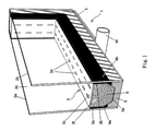
図1は、部分的な断面斜視図において、スペーサ2によって互いに距離をもって平行な位置でかつそろった端部を有して保持されている第1及び第2ガラスペイン2a、2bを有する絶縁グレージング1を、描写している。スペーサ3の2つのペイン接触表面3a、3bが、ブチルストリップ4a、4bを備えており、スペーサ3とガラスペイン2a、2bとの間の、耐蒸気拡散性の接続が実現されている。封止剤ストリップ5が、スペーサ3の外で、ペイン2a、2bの間の隙間に、アプリケーターロールWによって押し込まれ、ペインの間の物質的かつ耐水漏洩性の接続が確立され、絶縁グレージング1が完成する。
FIG. 1 is a partial cross-sectional perspective view of an insulating
スペーサ3は、矩形及び台形が長辺で互いに結合した断面を有しており、乾燥剤6のビーズで充填されており、かつ、小さい開口部3dを備えているグレージング内側壁3cを、有する。封止剤ストリップ5によって覆われているスペーサ3の壁を、下記において、スペーサの外側壁3eとして言及する。充填剤6によるスペーサ3の内部3fの充填は、開口部3dとともに、グレージング内部2cに侵入する湿分を吸収しペインの曇りが生じ得ないようにすることを、確実にする。
The
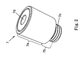
図2は、均圧要素7の斜視外部図であり、これは、図1に係る絶縁グレージング1に挿入されることが意図されている。図2A、2B、及び2Cは、そのような均圧要素の例示的な設計構成を描写している。
FIG. 2 is a perspective external view of the
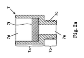
図2Aによれば、均圧要素7が、段階的な円錐形の基本形状を有しており、比較的大きい直径を有する第1主体部分7a、及び比較的小さい直径を有する第2主体部分7bを有している。第2主体部分は、ここでは、外部スレッド(外部ネジ山)7cを備えているが、差込みされてもよく又はクリップされてもよい。そのような均圧要素7を絶縁グレージング1にどのように配置するのかを、図3Dに描写しており、かつ、下記に記載している。均圧要素7が、図2で既に見ることができる第1開口部7dに加えて、第2開口部7eを有しており、これを、図2Aで見ることができる。
According to FIG. 2A, the
図2A~2Cは、おおよそ同一の収容構造を有している均圧要素7のありうる設計構成を示している。描写は、原則としてスケッチであることが理解される必要があり、それぞれの機能を実現するために合理的に使用される全ての部品を描写していることは主張されない。言うまでもないが、収容構造及び筐体の基本形状は、図2~図2Cに示されている描写から外れることができる。
2A-2C show possible design configurations of
図2Aは、均圧要素7へのメンブレン7fの取付を描写しており、このメンブレンは、初期の状態では超透過性であるが、材料の経年劣化に起因して、事前に決定された期間で、耐蒸気拡散性でありかつガス交換を防止するフィルムに変化し、例えば、ポリ(1-トリメチルシリル-1-プロピン)(PTMSP)又は類似の材料でできている。メンブレンの正確な組成、構造、及び厚みは、特定の用途に応じて選択され、特に、絶縁グレージングの完成から最終的な使用の場所へのその到着までとみなされる期間に依存しており、その期間の間に、それぞれの環境とグレージング内部との間の均圧が可能となる必要がある。
FIG. 2A depicts the attachment of the
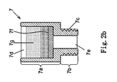
図2Bは、変形態様として、第1主体部分7aの底部に耐蒸気拡散性であるがガス透過性であるPTFEメンブレン7fが配置されている均圧要素7を、描写している。このメンブレンの上に、初期には容易にガスを透過するプラスチック材料7g、例えば、PEGの粉末、粒子、又は成形体が、注入又は配置されている。これによって、ガス透過性が、周囲雰囲気の湿分の影響の下で時間とともに実質的に低減される。意図される使用に応じて、この材料を、その化学組成及び導入の形態の点で選択することができ、それにより、ガス透過性の低減が事前に決定された期間にわたって起こるようにし(上記参照)、かつ、随意に、均圧要素の耐ガス漏洩的な完全な閉鎖をもたらすようにする。
FIG. 2B depicts, as a modification, a
図2Cは、別の変形態様として、水蒸気の通過を妨害するがガス透過性である耐水漏洩性PTFEメンブレン7fと、経年劣化の結果として又は周囲空気の構成要素(例えば、湿分)の影響の下で膨張する材料でできている成形体7gとが、互いに重なり合って配置されている。図では、成形体7gが、中央貫通開口部7hを有して描写されており、これが、膨張に起因して、徐々に閉じる。しかしながら、成形体が、複数の比較的小さい貫通開口部を有してもよく、又は、初期には比較的大きい細孔を有しており、この細孔が同様にそのサイズにおいて長期間にわたって減少し、場合によって最終的に完全に閉鎖されてもよい。上述の態様と同様に、均圧要素のこれらの構成要素の特定の材料及び設計構成を、特定の意図される使用に応じて、特には、ガス透過性における所望の時間依存的な減少に応じて、選択する。
FIG. 2C shows, as another modification, the water leak
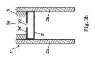
図3A~図3Dは、本発明に係る絶縁グレージング1’のスケッチ的な断面図において、その導入の必須工程を描写している。絶縁グレージング1’の構造は、大部分で、図1における絶縁グレージング1の構造に対応しており、対応する又は機能的に類似する部品が、図1と同じ参照番号で特定されており、ここでは詳述しない。図3A~図3Dは、乾燥剤が充填されておらず矩形断面を有するスペーサ3’を描写している。しかしながら、本発明に関して、図1に描写されている幾何学的構成及び乾燥剤充填を有するスペーサ3が、好ましくは使用されると考えてよい。また、スペーサ3’が、図1で描写されるブチルストリップ4a、4bを備えることができることも、想定される。
3A-3D depict the essential steps of its introduction in a sketchy cross-sectional view of the insulating glazing 1'according to the present invention. The structure of insulation glazing 1'corresponds to the structure of
図3Aは、封止剤ストリップ5の適用及びその硬化によって端部封止を完成させた後の絶縁グレージング1’を描写している。図3Bで見られるように、挿入されることとなる均圧要素の外部形状に適合している開口部5a又は3g’を、封止剤ストリップ5及び外側壁3e’に、それぞれ形成する。封止剤ストリップ5における開口部5aが、均圧要素の対応する寸法よりも大きい寸法であり、一方で、スペーサ3’の開口部3g’が、均圧要素の対応する寸法に正確に適合しており、例えば、それによって、部分的にネジ山を備えている均圧要素を、開口部3g’にねじ込む。
FIG. 3A depicts the insulation glazing 1'after the end encapsulation is completed by application of the
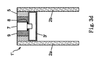
そして、図3Cによれば、ブチルコード8を備えている均圧要素7を、開口部5a、3g’の場所に持っていき、開口部に挿入し(例えば、開口部3g’にねじ込むことによって挿入し)、それにより、均圧要素がそこで強固に封止されるようにし、かつブチルコード8が弾性的に変形しそれによりそれがスペーサ3’の開口部3g’における耐蒸気拡散性の封止となるようにする。この状態が、図3Dに描写されており、また、ここでは、開口部5aの完全な弾性的充填のためのかつ絶縁グレージング端部の耐水漏洩性封止を復元するための封止剤リング9を、挿入された均圧要素7の周囲に射出していることを見ることができる。これで、描写されている絶縁グレージング1’の態様の製造が、完了する。
Then, according to FIG. 3C, the
さらには、本発明の態様は、ここで描写されている例示及び上記で明示的に示された本発明の側面の多数の変形態様において、可能である。
本開示は、下記の態様を含む:
<態様1>
第1ペイン(2a)及び第2ペイン(2b)、
前記第1及び前記第2ペインにそれぞれ耐水蒸気漏洩性の様式で強固に接続している、前記第1ペインと前記第2ペインとの間の、周縁スペーサ―(3、3’)、
を有する、絶縁グレージング(1、1’)であって、
前記スペーサが、少なくとも2つの平行なペイン接触壁、外側壁(3e、3e’)、及びグレージング内側壁(3c)、並びに内部(3f)を有し、かつ、耐水漏洩性の封止剤ストリップ(5)が、前記第1と前記第2ペインとの間でスペーサの前記外側壁の周りに延在しており、
少なくとも1つの均圧要素(7)が、前記封止剤ストリップ及び前記スペーサに挿入されており、前記均圧要素が、一方では周囲雰囲気に通じており、他方では、前記スペーサの前記内部又は前記第1ペインと前記第2ペインとの間のグレージング内部(2c)に通じており、かつ、前記均圧要素が、周囲雰囲気と前記スペーサの前記内部又は前記グレージング内部との間の均圧機能を有するガス接続を提供するように実施されており、このガス接続が、経年劣化及び/又は周囲雰囲気の影響に起因して時間的に限定されており、
前記均圧要素(7)が、主体(7a、7b)に、初期にはガス透過性である物質を含有しており、この物質が、経年劣化し、かつ/又は周囲雰囲気における湿分の影響の下で劣化し、前記均圧要素が完全に閉鎖されるまで、徐々に、前記均圧要素のガス透過性を低下させることを特徴とする、
絶縁グレージング(1、1’)。
<態様2>
前記劣化する物質(7g)が、特には外部側で、耐水漏洩性かつガス透過性であるが水蒸気の通過を妨害するメンブレン(7f)と一緒に、前記均圧要素(7)に充填されている、態様1に記載の絶縁グレージング(1、1’)。
<態様3>
前記劣化する物質が、ポリエチレングリコールの粉末又は粒子であり、かつ、前記耐水漏洩性の前記メンブレンが、PTFEメンブレンであり、特には延伸又は焼結PTFEメンブレンである、態様2に記載の絶縁グレージング(1、1’)。
<態様4>
前記経年劣化する物質が、前記主体(7a、7b)に、メンブレン(7f)として挿入されており、特にはPTSMPに基づいている、態様1に記載の絶縁グレージング(1、1’)。
<態様5>
前記劣化する物質が、特には内部側で、耐水漏洩性かつガス透過性であるが水蒸気の通過を妨害するメンブレン(7f)と一緒に、前記均圧要素(7)に挿入されており、
特には、耐水漏洩性の前記メンブレンが、PTFEメンブレンであり、かつ、前記劣化する物質が、湿分の影響の下で膨張する物質であり、初期には多孔性であるか又は開口部(7h)を備えている挿入体(7g)として存在する、
態様1に記載の絶縁グレージング(1、1’)。
<態様6>
前記スペーサ(3、3’)の前記グレージング内側壁(3c)が、ガス透過性であり、かつ、前記均圧要素(7)が、前記スペーサの前記内部(3f)に突き出しており、かつ、前記内部を、周囲雰囲気に、均圧化する様式で接続している、態様1~5のいずれか一項に記載の絶縁グレージング(1、1’)。
<態様7>
前記スペーサ(3、3’)の前記グレージング内側壁(3c)が、複数の小さい開口部(3d)を有しており、これらの開口部が、特には、前記スペーサの全長にわたって分布しており、かつ、前記スペーサの前記内部(3f)が、特には、乾燥剤(6)で充填されている、態様5に記載の絶縁グレージング(1、1’)。
<態様8>
前記均圧要素(7)が、前記スペーサ(3、3’)を貫通し、かつ前記グレージング内部(2c)に突出しており、前記内部を、周囲雰囲気に、均圧化する様式で接続している、態様1~6のいずれか一項に記載の絶縁グレージング(1、1’)。
<態様9>
前記均圧要素(7)の主体部分(7a)が、前記封止剤ストリップ(5)に埋め込まれており、かつ、その外部側で開かれており、かつ前記スペーサ(3、3’)の前記外側壁(3e)に固定されている、態様1~7のいずれか一項に記載の絶縁グレージング(1、1’)。
<態様10>
前記封止剤ストリップ(5)に埋め込まれている前記主体部分(7a)が、別個の耐水漏洩性の封止剤(9)によって囲まれており、かつ、前記スペーサ(3、3’)の前記外側壁(3e、3e’)における貫通開口部に、他の別個の耐水蒸気漏洩性の封止剤(8)を備えている、態様9に記載の絶縁グレージング(1、1’)。
<態様11>
前記均圧要素(7)の前記主体(7a、7b)が、本質的に、段階的な円錐状の形状を有している、態様1~10のいずれか一項に記載の絶縁グレージング(1、1’)。
<態様12>
前記別個の耐水漏洩性の封止剤(9)が、中空の円錐形又は環状の形状を有しており、他の前記別個の耐水蒸気漏洩性の封止剤(8)が、環状である、態様10又は11に記載の絶縁グレージング(1、1’)。
<態様13>
下記の工程を有する、態様1~12のいずれか一項に記載の絶縁グレージング(1、1’)を製造する方法:
- 前記第1及び第2ペイン(2a、2b)を平行に配置し、これらを、耐水蒸気漏洩性の様式で、前記スペーサ(3、3’)の前記第1及び第2ペイン接触壁(3a、3b)に、それぞれ接続することによって、絶縁グレージングを形成すること、
- 前記封止剤ストリップ(5)を、周縁的に、前記スペーサの前記外側壁(3e、3e’)に適用すること、
- 開口部(5a、3g’)を、前記封止剤ストリップの少なくとも1つの場所に、かつ少なくとも前記スペーサの前記外側壁(3e’)に、形成すること、
- 前記均圧要素(7)を、前記封止剤ストリップ及び前記スペーサの前記外側壁における開口部又はそれぞれの開口部に、耐ガス漏洩性の様式で、挿入すること、ここで、前記均圧要素が、主体(7a、7b)に、初期にはガス透過性である物質を含有しており、この物質が、経年劣化しかつ/又は周囲雰囲気における湿分の影響下で劣化し、かつ、前記均圧要素が完全に閉鎖されるまで、前記均圧要素のガス透過性を徐々に低下させる。
<態様14>
前記封止剤ストリップ(5)の前記開口部(5a)に挿入する前に、前記均圧要素(7)に、別個の耐水蒸気漏洩性の封止剤(8)を提供する、態様13に記載の方法。
<態様15>
前記封止剤ストリップ(5)における前記開口部(5a)が、前記均圧要素(7)の外部寸法よりも大きい寸法を有しており、かつ、前記均圧要素の挿入の後で、均圧要素の外部輪郭と前記開口部の内側壁との間の隙間を、封止加工物を射出して別個の耐水漏洩性封止(9)を形成することによって充填する、態様13又は14に記載の方法。
Furthermore, aspects of the invention are possible in a number of variations of the embodiments depicted herein and the aspects of the invention explicitly shown above.
The disclosure includes the following aspects:
<
1st pane (2a) and 2nd pane (2b),
Peripheral spacers (3, 3') between the first pane and the second pane, which are firmly connected to the first and second panes in a water vapor leak resistant manner, respectively.
Insulation glazing (1, 1')
The spacer has at least two parallel pane contact walls, an outer wall (3e, 3e'), and a glazing inner wall (3c), as well as an interior (3f), and a water leak resistant sealant strip (3e). 5) extends around the outer wall of the spacer between the first and second panes.
At least one pressure equalizing element (7) is inserted into the encapsulant strip and the spacer, the pressure equalizing element being open to the ambient atmosphere on the one hand and inside or said the spacer on the other hand. The pressure equalizing element communicates with the inside of the glazing (2c) between the first pane and the second pane, and the pressure equalizing element provides a pressure equalizing function between the ambient atmosphere and the inside of the spacer or the inside of the glazing. It is implemented to provide a gas connection that has, and this gas connection is temporally limited due to aging and / or the influence of the ambient atmosphere.
The pressure equalizing element (7) contains a substance that is initially gas permeable in the main body (7a, 7b), and this substance deteriorates over time and / or is affected by moisture in the surrounding atmosphere. It is characterized by gradually reducing the gas permeability of the pressure equalizing element until it deteriorates underneath and the pressure equalizing element is completely closed.
Insulation glazing (1, 1').
<Aspect 2>
The deteriorating substance (7 g) is filled in the pressure equalizing element (7) together with a membrane (7f) which is water leak resistant and gas permeable but obstructs the passage of water vapor, especially on the outside side. The insulating glazing according to aspect 1 (1, 1').
<
The insulating glazing according to aspect 2, wherein the deteriorating substance is polyethylene glycol powder or particles, and the water leak resistant membrane is a PTFE membrane, particularly a stretched or sintered PTFE membrane. 1, 1').
<Aspect 4>
The insulating glazing (1, 1') according to
<
The degrading substance is inserted into the pressure equalizing element (7) together with a membrane (7f) that is water leak resistant and gas permeable but obstructs the passage of water vapor, especially on the internal side.
In particular, the water leak resistant membrane is a PTFE membrane and the degrading substance is a substance that expands under the influence of moisture and is initially porous or has an opening (7h). ) Exists as an insert (7 g),
Insulation glazing according to aspect 1 (1, 1').
<Aspect 6>
The glazing inner side wall (3c) of the spacer (3, 3') is gas permeable, and the pressure equalizing element (7) protrudes into the inside (3f) of the spacer. The insulating glazing (1, 1') according to any one of
<
The glazing inner wall (3c) of the spacers (3, 3') has a plurality of small openings (3d), which are particularly distributed over the entire length of the spacer. The insulating glazing (1, 1') according to
<
The pressure equalizing element (7) penetrates the spacer (3, 3') and protrudes into the glazing interior (2c), and the interior is connected to the surrounding atmosphere in a pressure equalizing manner. The insulating glazing (1, 1') according to any one of
<
The main body portion (7a) of the pressure equalizing element (7) is embedded in the encapsulant strip (5) and is open on the outer side thereof, and the spacer (3, 3'). The insulating glazing (1, 1') according to any one of
<Aspect 10>
The main body portion (7a) embedded in the sealant strip (5) is surrounded by a separate water leak resistant sealant (9) and is of the spacer (3, 3'). The insulating glazing (1, 1') according to
<Aspect 11>
The insulating glazing (1) according to any one of
<Aspect 12>
The separate water vapor leak resistant sealant (9) has a hollow conical or annular shape, and the other separate water vapor leak resistant sealant (8) is annular. , The insulating glazing (1, 1') according to aspect 10 or 11.
<Aspect 13>
The method for producing the insulating glazing (1, 1') according to any one of
-The first and second panes (2a, 2b) are arranged in parallel, and these are arranged in the form of water vapor leakage resistance to the first and second pane contact walls (3a) of the spacer (3, 3'). Forming insulating glazing by connecting to 3b), respectively,
-Applying the encapsulant strip (5) peripherally to the outer wall (3e, 3e') of the spacer.
-Forming an opening (5a, 3g') at at least one location on the encapsulant strip and at least on the outer wall (3e') of the spacer.
-The pressure equalizing element (7) is inserted into or each opening in the outer wall of the sealant strip and the spacer in a gas leak resistant manner, wherein the pressure equalizing element (7) is inserted. The element contains a substance that is initially gas permeable in the main body (7a, 7b), and this substance deteriorates over time and / or deteriorates under the influence of moisture in the surrounding atmosphere, and The gas permeability of the pressure equalizing element is gradually reduced until the pressure equalizing element is completely closed.
<Aspect 14>
13. Aspects 13 provide the pressure equalizing element (7) with a separate water vapor leak resistant sealant (8) prior to insertion into the opening (5a) of the sealant strip (5). The method described.
<Aspect 15>
The opening (5a) in the encapsulant strip (5) has a dimension larger than the external dimension of the pressure equalizing element (7) and is leveled after the insertion of the pressure equalizing element. In aspects 13 or 14, the gap between the outer contour of the pressure element and the inner wall of the opening is filled by injecting a sealing work piece to form a separate water leak resistant seal (9). The method described.
1、1’ 絶縁グレージング
2a、2b ガラスペイン
2c グレージング内部
3、3’ スペーサ
3a、3b ペイン接触壁
3c グレージング内部壁
3d 小さい開口部
3e、3e’ 外側壁
3f スペーサの内部
3g、3g’ スペーサの開口部
4a、4b ブチルストリップ
5 封止剤ストリップ
5a 封止剤ストリップの開口部
6 乾燥剤
7 均圧要素
7a、7b 主体部分
7c ネジ山
7d、7e 均圧要素の開口部
7f メンブレン
7g プラスチック粒子又はプラスチック主体
7h 成形体における開口部
8 ブチルコード
9 封止化合物のリング
W 適用ロール
1,
Claims (15)
前記第1及び前記第2ペインにそれぞれ耐水蒸気漏洩性の様式で強固に接続している、前記第1ペインと前記第2ペインとの間の、周縁スペーサ―(3、3’)、
を有する、絶縁グレージング(1、1’)であって、
前記スペーサが、少なくとも2つの平行なペイン接触壁、外側壁(3e、3e’)、及びグレージング内側壁(3c)、並びに内部(3f)を有し、かつ、耐水漏洩性の封止剤ストリップ(5)が、前記第1ペインと前記第2ペインとの間でスペーサの前記外側壁の周りに延在しており、
少なくとも1つの均圧要素(7)が、前記封止剤ストリップ及び前記スペーサに挿入されており、前記均圧要素が、一方では周囲雰囲気に通じており、他方では、前記スペーサの前記内部又は前記第1ペインと前記第2ペインとの間のグレージング内部(2c)に通じており、かつ、前記均圧要素が、周囲雰囲気と前記スペーサの前記内部又は前記グレージング内部との間の均圧機能を有するガス接続を提供するように実施されており、このガス接続が、経年劣化及び/又は周囲雰囲気の影響に起因して時間的に限定されており、
前記均圧要素(7)が、主体(7a、7b)に、初期にはガス透過性である物質を含有しており、この物質が、経年劣化し、かつ/又は周囲雰囲気における湿分の影響の下で劣化し、前記均圧要素が完全に閉鎖されるまで、徐々に、前記均圧要素のガス透過性を低下させることを特徴とする、
絶縁グレージング(1、1’)。 1st pane (2a) and 2nd pane (2b),
Peripheral spacers (3, 3') between the first pane and the second pane, which are firmly connected to the first and second panes in a water vapor leak resistant manner, respectively.
Insulation glazing (1, 1')
The spacer has at least two parallel pane contact walls, an outer wall (3e, 3e'), and a glazing inner wall (3c), as well as an interior (3f), and a water leak resistant sealant strip (3e). 5) extends around the outer wall of the spacer between the first pane and the second pane.
At least one pressure equalizing element (7) is inserted into the encapsulant strip and the spacer, the pressure equalizing element being open to the ambient atmosphere on the one hand and inside or said the spacer on the other hand. The pressure equalizing element communicates with the inside of the glazing (2c) between the first pane and the second pane, and the pressure equalizing element provides a pressure equalizing function between the ambient atmosphere and the inside of the spacer or the inside of the glazing. It is implemented to provide a gas connection that has, and this gas connection is temporally limited due to aging and / or the influence of the ambient atmosphere.
The pressure equalizing element (7) contains a substance that is initially gas permeable in the main body (7a, 7b), and this substance deteriorates over time and / or is affected by moisture in the surrounding atmosphere. It is characterized by gradually reducing the gas permeability of the pressure equalizing element until it deteriorates underneath and the pressure equalizing element is completely closed.
Insulation glazing (1, 1').
特には、耐水漏洩性の前記メンブレンが、PTFEメンブレンであり、かつ、前記物質が、湿分の影響の下で膨張する物質であり、初期には多孔性であるか又は開口部(7h)を備えている挿入体(7g)として存在する、
請求項1に記載の絶縁グレージング(1、1’)。 The material is inserted into the pressure equalizing element (7), especially on the internal side, together with a membrane (7f) that is water leak resistant and gas permeable but obstructs the passage of water vapor.
In particular, the water leak resistant membrane is a PTFE membrane and the material expands under the influence of moisture and is initially porous or has an opening (7h). ) Exists as an insert (7 g),
The insulating glazing according to claim 1 (1, 1').
- 前記第1及び第2ペイン(2a、2b)を平行に配置し、これらを、耐水蒸気漏洩性の様式で、前記スペーサ(3、3’)の前記第1及び第2ペイン接触壁(3a、3b)に、それぞれ接続することによって、絶縁グレージングを形成すること、
- 前記封止剤ストリップ(5)を、周縁的に、前記スペーサの前記外側壁(3e、3e’)に適用すること、
- 開口部(5a、3g’)を、前記封止剤ストリップの少なくとも1つの場所に、かつ少なくとも前記スペーサの前記外側壁(3e’)に、形成すること、
- 前記均圧要素(7)を、前記封止剤ストリップ及び前記スペーサの前記外側壁における開口部又はそれぞれの開口部に、耐ガス漏洩性の様式で、挿入すること、ここで、前記均圧要素が、主体(7a、7b)に、初期にはガス透過性である物質を含有しており、この物質が、経年劣化しかつ/又は周囲雰囲気における湿分の影響下で劣化し、かつ、前記均圧要素が完全に閉鎖されるまで、前記均圧要素のガス透過性を徐々に低下させる。 The method for producing the insulating glazing (1, 1') according to any one of claims 1 to 12, which comprises the following steps:
-The first and second panes (2a, 2b) are arranged in parallel, and these are arranged in the form of water vapor leakage resistance to the first and second pane contact walls (3a) of the spacer (3, 3'). Forming insulating glazing by connecting to 3b), respectively,
-Applying the encapsulant strip (5) peripherally to the outer wall (3e, 3e') of the spacer.
-Forming an opening (5a, 3g') at at least one location on the encapsulant strip and at least on the outer wall (3e') of the spacer.
-The pressure equalizing element (7) is inserted into or each opening in the outer wall of the sealant strip and the spacer in a gas leak resistant manner, wherein the pressure equalizing element (7) is inserted. The element contains a substance that is initially gas permeable in the main body (7a, 7b), and this substance deteriorates over time and / or deteriorates under the influence of moisture in the surrounding atmosphere, and The gas permeability of the pressure equalizing element is gradually reduced until the pressure equalizing element is completely closed.
Applications Claiming Priority (3)
| Application Number | Priority Date | Filing Date | Title |
|---|---|---|---|
| EP18151865.5 | 2018-01-16 | ||
| EP18151865 | 2018-01-16 | ||
| PCT/EP2018/086191 WO2019141484A1 (en) | 2018-01-16 | 2018-12-20 | Insulating glazing and method for producing same |
Publications (2)
| Publication Number | Publication Date |
|---|---|
| JP2021510669A JP2021510669A (en) | 2021-04-30 |
| JP7011069B2 true JP7011069B2 (en) | 2022-02-10 |
Family
ID=61002854
Family Applications (1)
| Application Number | Title | Priority Date | Filing Date |
|---|---|---|---|
| JP2020538969A Expired - Fee Related JP7011069B2 (en) | 2018-01-16 | 2018-12-20 | Insulation glazing and its manufacturing method |
Country Status (12)
| Country | Link |
|---|---|
| US (1) | US11441351B2 (en) |
| EP (1) | EP3740641B1 (en) |
| JP (1) | JP7011069B2 (en) |
| KR (1) | KR20200110689A (en) |
| CN (1) | CN111615579B (en) |
| CL (1) | CL2020001613A1 (en) |
| DK (1) | DK3740641T3 (en) |
| MX (1) | MX2020007568A (en) |
| NZ (1) | NZ766175A (en) |
| PL (1) | PL3740641T3 (en) |
| RU (1) | RU2745783C1 (en) |
| WO (1) | WO2019141484A1 (en) |
Families Citing this family (6)
| Publication number | Priority date | Publication date | Assignee | Title |
|---|---|---|---|---|
| DK3394379T3 (en) * | 2017-03-10 | 2020-05-11 | Allmetal Inc | Double glazing distance construction |
| WO2020247427A1 (en) * | 2019-06-04 | 2020-12-10 | Plastpro 2000, Inc. | Door comprising vented stile, and method of making the same |
| EP3783183A1 (en) | 2019-08-22 | 2021-02-24 | Saint-Gobain Glass France | Method and assembly for handling an insulating glazing unit with a pressure compensation element |
| WO2021156401A1 (en) * | 2020-02-07 | 2021-08-12 | Saint-Gobain Glass France | Glazing having an rfid transponder |
| DE202021103997U1 (en) * | 2021-07-27 | 2022-10-28 | Prof. Michael Lange Ingenieurgesellschaft mbh | Two-shell facade element |
| CZ2022228A3 (en) * | 2022-05-30 | 2023-07-05 | VoltGlass s.r.o. | Heating glass and glass filling of the window structure containing this heating glass |
Citations (5)
| Publication number | Priority date | Publication date | Assignee | Title |
|---|---|---|---|---|
| US20070033887A1 (en) | 2003-09-26 | 2007-02-15 | Ambrose David H | System for alleviating in-vault condensation in double-glazed windows |
| JP2012101987A (en) | 2010-11-12 | 2012-05-31 | Thermo Work:Kk | Multiple-layer glass |
| JP2014527502A (en) | 2011-07-20 | 2014-10-16 | エージーシー グラス ユーロップ | Insulated flat glass panel including at least one internal space including a layer of insulating gas, and method for manufacturing such flat glass panel |
| JP2015102132A (en) | 2013-11-22 | 2015-06-04 | 日本トレルボルグ シーリング ソリューションズ株式会社 | Seal structure |
| JP2016506465A (en) | 2012-12-20 | 2016-03-03 | サン−ゴバン グラス フランスSaint−Gobain Glass France | Insulated glass window with pressure compensation element |
Family Cites Families (64)
| Publication number | Priority date | Publication date | Assignee | Title |
|---|---|---|---|---|
| US2880475A (en) * | 1957-05-10 | 1959-04-07 | Mills Prod Inc | Window unit |
| LU65310A1 (en) | 1972-05-08 | 1973-11-22 | ||
| US3932971A (en) * | 1973-05-21 | 1976-01-20 | Day Ralph K | Window construction |
| US4222213A (en) * | 1978-11-14 | 1980-09-16 | Gerald Kessler | Insulating spacer for double insulated glass |
| FR2552153B1 (en) | 1983-09-15 | 1987-07-10 | Ouest Vitrages Isolants | ELEMENT FOR DOOR OR WINDOW OR FRONT PANEL, INCLUDING TWO PLANE PANELS SEPARATED BY GAS WITH COMPENSATED VOLUME VARIATION |
| US4952430A (en) * | 1985-05-16 | 1990-08-28 | Ppg Industries, Inc. | Insulated window units |
| US4627206A (en) * | 1985-09-12 | 1986-12-09 | Rollscreen Company | Window sash breather device |
| GB2192207B (en) * | 1986-07-04 | 1990-11-14 | Pilkington Brothers Plc | An opaque cladding panel |
| CA1285177C (en) | 1986-09-22 | 1991-06-25 | Michael Glover | Multiple pane sealed glazing unit |
| DE3808907A1 (en) | 1988-03-17 | 1989-10-05 | Peter Dipl Ing Kueffner | Multiple glazing unit |
| DE3842129A1 (en) | 1988-12-15 | 1990-06-21 | Flachglas Ag | Pressure-compensation device for insulating glass panes |
| CH681102A5 (en) * | 1990-08-10 | 1993-01-15 | Geilinger Ag | |
| JPH04189997A (en) * | 1990-11-21 | 1992-07-08 | Nippon Fukusoo Glass Kk | Balance between inside and outside pressure of double layer glass |
| JPH0626282A (en) * | 1992-07-06 | 1994-02-01 | Nippon Sheet Glass Co Ltd | Multilayer glass |
| DE59306331D1 (en) * | 1992-12-10 | 1997-06-05 | Thermix Gmbh Isolationssysteme | Spacers |
| US5394671A (en) * | 1993-10-13 | 1995-03-07 | Taylor; Donald M. | Cardboard spacer/seal as thermal insulator |
| US5461840A (en) * | 1993-10-13 | 1995-10-31 | Taylor; Donald M. | Cardboard spacer/seal as thermal insulator |
| DE19506119A1 (en) | 1995-02-22 | 1996-08-29 | Schulz Siegfried Dipl Wirtsch | Double glazing window unit with variable insulation and light absorption property |
| US5962090A (en) * | 1995-09-12 | 1999-10-05 | Saint-Gobain Vitrage Suisse Ag | Spacer for an insulating glazing assembly |
| IT1287228B1 (en) * | 1996-04-10 | 1998-08-04 | Finvetro Srl | DEVICE PARTICULARLY FOR COMPENSATION BETWEEN INTERNAL AND EXTERNAL PRESSURES IN A GLASS |
| US5873203A (en) * | 1997-09-02 | 1999-02-23 | Ppg Industries, Inc. | Photoelectrolytically-desiccating multiple-glazed window units |
| DE19805348A1 (en) * | 1998-02-11 | 1999-08-12 | Caprano & Brunnhofer | Spacer profile for insulating washer unit |
| DE29807418U1 (en) * | 1998-04-27 | 1999-06-24 | Flachglas AG, 90766 Fürth | Spacer profile for insulating washer unit |
| US7976916B2 (en) | 1999-05-25 | 2011-07-12 | Saint-Gobain Vitrage | Refrigerated display case having a transparent insulating glazing unit |
| US6553728B1 (en) * | 2000-11-20 | 2003-04-29 | Cardinal Ig Company | Insulating glass unit pressure equalization valve |
| US7743584B2 (en) * | 2001-08-09 | 2010-06-29 | Edgetech I.G., Inc. | Spacer assembly for insulating glazing units and method for fabricating the same |
| CN2616536Y (en) * | 2003-04-17 | 2004-05-19 | 冷冰 | Polyester diaphragm multilayer hollow glass |
| US7997037B2 (en) * | 2003-06-23 | 2011-08-16 | Ppg Industries Ohio, Inc. | Integrated window sash with groove for desiccant material |
| CN1867749B (en) * | 2003-06-23 | 2011-10-05 | Ppg工业俄亥俄公司 | Integrated window sash and methods of making an integrated window sash |
| US8112860B2 (en) * | 2003-12-17 | 2012-02-14 | Stephen Collins | Method of treating glazing panels |
| RU41068U1 (en) * | 2004-05-31 | 2004-10-10 | Куликов Олег Николаевич | GLASS SEALING DEVICE |
| DE102005002285A1 (en) | 2005-01-18 | 2006-07-27 | Fredy Zisser | Air pressure equalization system for use in interspace between panes of e.g. noise protection insulating glasses, has valve that keeps remaining portion of volume high in membrane tube, so that positive pressure of glass is adjusted |
| AU2006275096B2 (en) * | 2005-08-01 | 2010-07-01 | Technoform Glass Insulation Holding Gmbh | Spacer arrangement with fusable connector for insulating glass units |
| US8597741B2 (en) * | 2005-11-18 | 2013-12-03 | Momentive Performance Materials Inc. | Insulated glass unit possessing room temperature-cured siloxane sealant composition of reduced gas permeability |
| US8257805B2 (en) * | 2006-01-09 | 2012-09-04 | Momentive Performance Materials Inc. | Insulated glass unit possessing room temperature-curable siloxane-containing composition of reduced gas permeability |
| US8099916B2 (en) * | 2006-11-03 | 2012-01-24 | Mickael Collins Joasil | Ventilation system for multi-paned windows |
| DE102007028911A1 (en) * | 2007-06-22 | 2009-01-02 | Solan Gmbh | Pressure equalization device for a gas volume containing insulating glass units |
| ITTV20080031A1 (en) * | 2008-02-20 | 2009-08-21 | For El Base Di Vianello Fortunato & C Snc | AUTOMATIC DEVICE AND AUTOMATIC PROCEDURE FOR FILLING THE INSULATING GLASS CONSISTING OF AT LEAST TWO GLASS SHEETS AND AT LEAST A SPACER FRAME WITH GAS OTHER THAN AIR. |
| US10000411B2 (en) * | 2010-01-16 | 2018-06-19 | Cardinal Cg Company | Insulating glass unit transparent conductivity and low emissivity coating technology |
| DE102010006127A1 (en) * | 2010-01-29 | 2011-08-04 | Technoform Glass Insulation Holding GmbH, 34277 | Spacer profile with reinforcement layer |
| DE102011009359A1 (en) * | 2011-01-25 | 2012-07-26 | Technoform Glass Insulation Holding Gmbh | Spacer profile and insulating disk unit with such a spacer profile |
| CN202227901U (en) * | 2011-09-15 | 2012-05-23 | 郑琳 | Hollow shutter glass partition frame with pressure regulation function |
| KR101672109B1 (en) * | 2012-01-13 | 2016-11-02 | 쌩-고벵 글래스 프랑스 | Spacer for insulating glazing units |
| CN202742747U (en) * | 2012-06-13 | 2013-02-20 | 中国建材检验认证集团股份有限公司 | Pressure auto-balance deformation-free vacuum glass composite structure |
| US8898973B2 (en) * | 2013-02-25 | 2014-12-02 | Solar Innovations, Inc. | Building cavity ventilation system |
| EP2966047B1 (en) * | 2013-03-04 | 2020-11-18 | Panasonic Intellectual Property Management Co., Ltd. | Method for producing multiple pane glass |
| US8875456B2 (en) * | 2013-03-14 | 2014-11-04 | Ply Gem Industries, Inc. | Pressure stabilization device |
| EP3080376A1 (en) * | 2013-12-12 | 2016-10-19 | Saint-Gobain Glass France | Spacer for insulating glazing units, comprising extruded profiled seal |
| US10221612B2 (en) * | 2014-02-04 | 2019-03-05 | View, Inc. | Infill electrochromic windows |
| US10301868B2 (en) * | 2014-06-27 | 2019-05-28 | Saint-Gobain Glass France | Insulated glazing comprising a spacer, and production method |
| US10125537B2 (en) * | 2014-07-18 | 2018-11-13 | Litezone Technologies Inc. | Pressure compensated glass unit |
| CZ2014587A3 (en) * | 2014-08-29 | 2016-01-06 | Jiří Dobrovolný | Insulation glass and process for producing thereof |
| MX374373B (en) * | 2014-09-25 | 2025-03-06 | Saint Gobain | SEPARATOR FOR INSULATING GLAZING UNITS. |
| EP3230545A1 (en) * | 2014-12-08 | 2017-10-18 | Saint-Gobain Glass France | Spacer for insulated glazing |
| DK3265636T3 (en) * | 2015-03-02 | 2022-05-23 | Saint Gobain | GLASS FIBER-REINFORCED SPACER FOR INSULATION WINDOW, PROCEDURE FOR MANUFACTURE THIS AND USE OF SUCH A SPACER IN MULTI-LAYER WINDOWS |
| US20180195339A1 (en) * | 2015-10-13 | 2018-07-12 | Saint-Gobain Glass France | Connector for connecting two hollow profiles, comprising a membrane |
| CN105257173A (en) * | 2015-10-29 | 2016-01-20 | 深圳市光华中空玻璃工程有限公司重庆分公司 | Self-balancing hollow glass |
| PL3393308T3 (en) * | 2015-12-21 | 2021-03-08 | Saint-Gobain Glass France | Insulating glass element for a refrigerated cabinet |
| KR20190034613A (en) * | 2016-08-09 | 2019-04-02 | 쌩-고벵 글래스 프랑스 | Insulating glazing units with pyrotechnic modules |
| BR112019004324A2 (en) * | 2016-09-20 | 2019-05-28 | Saint Gobain | insulation vitrification and use |
| ES2895682T3 (en) * | 2017-12-07 | 2022-02-22 | Saint Gobain | Insulating glazing comprising a pressure compensation body with membrane and capillary |
| US20210079716A1 (en) * | 2018-01-22 | 2021-03-18 | Saint-Gobain Glass France | Spacer for insulating glazings, comprising an electric feed line integrated into a hollow chamber |
| CN112352087A (en) * | 2018-07-04 | 2021-02-09 | 法国圣戈班玻璃厂 | Covering elements for bus bars |
| WO2020053082A1 (en) * | 2018-09-13 | 2020-03-19 | Saint-Gobain Glass France | Spacer with metal side sections |
-
2018
- 2018-12-20 JP JP2020538969A patent/JP7011069B2/en not_active Expired - Fee Related
- 2018-12-20 KR KR1020207023701A patent/KR20200110689A/en not_active Abandoned
- 2018-12-20 US US16/962,467 patent/US11441351B2/en active Active
- 2018-12-20 CN CN201880086780.2A patent/CN111615579B/en not_active Expired - Fee Related
- 2018-12-20 WO PCT/EP2018/086191 patent/WO2019141484A1/en not_active Ceased
- 2018-12-20 PL PL18822081.8T patent/PL3740641T3/en unknown
- 2018-12-20 DK DK18822081.8T patent/DK3740641T3/en active
- 2018-12-20 MX MX2020007568A patent/MX2020007568A/en unknown
- 2018-12-20 RU RU2020120953A patent/RU2745783C1/en active
- 2018-12-20 EP EP18822081.8A patent/EP3740641B1/en active Active
- 2018-12-20 NZ NZ766175A patent/NZ766175A/en not_active IP Right Cessation
-
2020
- 2020-06-16 CL CL2020001613A patent/CL2020001613A1/en unknown
Patent Citations (5)
| Publication number | Priority date | Publication date | Assignee | Title |
|---|---|---|---|---|
| US20070033887A1 (en) | 2003-09-26 | 2007-02-15 | Ambrose David H | System for alleviating in-vault condensation in double-glazed windows |
| JP2012101987A (en) | 2010-11-12 | 2012-05-31 | Thermo Work:Kk | Multiple-layer glass |
| JP2014527502A (en) | 2011-07-20 | 2014-10-16 | エージーシー グラス ユーロップ | Insulated flat glass panel including at least one internal space including a layer of insulating gas, and method for manufacturing such flat glass panel |
| JP2016506465A (en) | 2012-12-20 | 2016-03-03 | サン−ゴバン グラス フランスSaint−Gobain Glass France | Insulated glass window with pressure compensation element |
| JP2015102132A (en) | 2013-11-22 | 2015-06-04 | 日本トレルボルグ シーリング ソリューションズ株式会社 | Seal structure |
Also Published As
| Publication number | Publication date |
|---|---|
| US20210071466A1 (en) | 2021-03-11 |
| MX2020007568A (en) | 2020-09-03 |
| EP3740641B1 (en) | 2022-05-04 |
| WO2019141484A1 (en) | 2019-07-25 |
| RU2745783C1 (en) | 2021-03-31 |
| PL3740641T3 (en) | 2022-07-18 |
| DK3740641T3 (en) | 2022-06-13 |
| US11441351B2 (en) | 2022-09-13 |
| CL2020001613A1 (en) | 2020-11-06 |
| CN111615579B (en) | 2022-04-19 |
| EP3740641A1 (en) | 2020-11-25 |
| NZ766175A (en) | 2022-08-26 |
| CN111615579A (en) | 2020-09-01 |
| JP2021510669A (en) | 2021-04-30 |
| KR20200110689A (en) | 2020-09-24 |
Similar Documents
| Publication | Publication Date | Title |
|---|---|---|
| JP7011069B2 (en) | Insulation glazing and its manufacturing method | |
| KR102119987B1 (en) | Connector for connecting two hollow-profile strips with membrane | |
| JP6165266B2 (en) | Insulated glass window with pressure compensation element | |
| KR20180053334A (en) | Corner connector with capillary | |
| US4357187A (en) | Window overlay for thermal insulation | |
| ES2895682T3 (en) | Insulating glazing comprising a pressure compensation body with membrane and capillary | |
| JP2659791B2 (en) | Waterproof oxygen sensor | |
| US20160290032A1 (en) | Spacer for insulating glazing units, comprising extruded profiled seal | |
| KR20160095128A (en) | Double glazing having improved sealing | |
| JP2023531226A (en) | Insulating glazing with spacers with reinforcing profiles | |
| US20220034152A1 (en) | Spacer with metallic side sections | |
| JPH0253596B2 (en) | ||
| JPH02238354A (en) | Waterproof type oxygen sensor | |
| CN218758014U (en) | Rain-proof water seepage sealing strip | |
| JP2019529748A (en) | Modular system for multilayer insulation glazing unit, multilayer insulation glazing unit, and method for manufacturing the multilayer insulation glazing unit | |
| JP7232689B2 (en) | Sealing material and building member structure | |
| JPH1192180A (en) | Method for balancing internal and external pressures of double layer glass | |
| US20250250847A1 (en) | Insulating glass units, spacers for insulating glass units, and methods for producing insulating glass units | |
| US12359498B2 (en) | Method of forming a maintenance-free rolling door vacuum slat | |
| KR102274366B1 (en) | Safety windows of gas-filled | |
| JPH0141073Y2 (en) | ||
| AU577694B2 (en) | Prefabricated spacer and corner piece for multiple-glazed windows | |
| JP3104165U (en) | Anti-condensation material | |
| JPH0730855Y2 (en) | Dew condensation prevention structure around metal sash | |
| KR20040064192A (en) | Structure of window chassis which can put laminated glass |
Legal Events
| Date | Code | Title | Description |
|---|---|---|---|
| A621 | Written request for application examination |
Free format text: JAPANESE INTERMEDIATE CODE: A621 Effective date: 20200714 |
|
| A977 | Report on retrieval |
Free format text: JAPANESE INTERMEDIATE CODE: A971007 Effective date: 20210823 |
|
| A131 | Notification of reasons for refusal |
Free format text: JAPANESE INTERMEDIATE CODE: A131 Effective date: 20210831 |
|
| A521 | Request for written amendment filed |
Free format text: JAPANESE INTERMEDIATE CODE: A523 Effective date: 20211129 |
|
| TRDD | Decision of grant or rejection written | ||
| A01 | Written decision to grant a patent or to grant a registration (utility model) |
Free format text: JAPANESE INTERMEDIATE CODE: A01 Effective date: 20211214 |
|
| A61 | First payment of annual fees (during grant procedure) |
Free format text: JAPANESE INTERMEDIATE CODE: A61 Effective date: 20220113 |
|
| R150 | Certificate of patent or registration of utility model |
Ref document number: 7011069 Country of ref document: JP Free format text: JAPANESE INTERMEDIATE CODE: R150 |
|
| LAPS | Cancellation because of no payment of annual fees |