JP2015102132A - Seal structure - Google Patents
Seal structure Download PDFInfo
- Publication number
- JP2015102132A JP2015102132A JP2013242031A JP2013242031A JP2015102132A JP 2015102132 A JP2015102132 A JP 2015102132A JP 2013242031 A JP2013242031 A JP 2013242031A JP 2013242031 A JP2013242031 A JP 2013242031A JP 2015102132 A JP2015102132 A JP 2015102132A
- Authority
- JP
- Japan
- Prior art keywords
- seal
- deformation
- seal end
- expansion coefficient
- linear expansion
- Prior art date
- Legal status (The legal status is an assumption and is not a legal conclusion. Google has not performed a legal analysis and makes no representation as to the accuracy of the status listed.)
- Pending
Links
Images


Classifications
-
- F—MECHANICAL ENGINEERING; LIGHTING; HEATING; WEAPONS; BLASTING
- F16—ENGINEERING ELEMENTS AND UNITS; GENERAL MEASURES FOR PRODUCING AND MAINTAINING EFFECTIVE FUNCTIONING OF MACHINES OR INSTALLATIONS; THERMAL INSULATION IN GENERAL
- F16K—VALVES; TAPS; COCKS; ACTUATING-FLOATS; DEVICES FOR VENTING OR AERATING
- F16K5/00—Plug valves; Taps or cocks comprising only cut-off apparatus having at least one of the sealing faces shaped as a more or less complete surface of a solid of revolution, the opening and closing movement being predominantly rotary
- F16K5/08—Details
- F16K5/14—Special arrangements for separating the sealing faces or for pressing them together
- F16K5/20—Special arrangements for separating the sealing faces or for pressing them together for plugs with spherical surfaces
- F16K5/201—Special arrangements for separating the sealing faces or for pressing them together for plugs with spherical surfaces with the housing or parts of the housing mechanically pressing the seal against the plug
Abstract
Description
本発明は、シール構造に係り、より詳細には、特に、低温の流体の漏れを良好に防止するためのシール構造に関する。 The present invention relates to a seal structure, and more particularly to a seal structure for preventing a low-temperature fluid from leaking well.
従来の流体のシール構造として、パッキン及びOリング等が知られている。 As a conventional fluid seal structure, a packing, an O-ring and the like are known.
しかしながら、例えば約−196℃等の低温の流体が流れる環境においては、Oリング等は硬化してしまい、シール性能が低下するという問題がある。 However, in an environment where a low-temperature fluid such as about -196 ° C. flows, there is a problem that the O-ring or the like is cured and the sealing performance is deteriorated.
また、例えば約−196℃等の低温状態において硬化しにくい樹脂製のシール部材を採用することが考えられる。しかしながら、樹脂シール部材は、線膨張係数(熱膨張率)が比較的高いため、低温状態において収縮変形してしまい、シール性能が低下するという問題がある。 In addition, for example, it is conceivable to employ a resin seal member that is hard to be cured at a low temperature such as about −196 ° C. However, since the resin seal member has a relatively high linear expansion coefficient (thermal expansion coefficient), there is a problem that the resin seal member contracts and deforms in a low temperature state, resulting in a decrease in sealing performance.
本発明は、上述した従来技術の問題点を解決するためになされたものであり、特に、低温状態でもシール性能を発揮することができ、良好に流体の漏洩を抑制することができるシール構造を提供することを目的としている。 The present invention has been made in order to solve the above-described problems of the prior art, and in particular, has a sealing structure that can exhibit sealing performance even in a low temperature state and can satisfactorily suppress fluid leakage. It is intended to provide.
上記の目的を達成するために、本発明は、第1の機械部品の第1の面と、この第1の面と対向する第2の機械部品の第2の面との間の隙間をシールするためのシール構造であって、第1の面に沿って延びる第1シール端部と、第2の面に沿って延びる第2シール端部と、第1シール端部と第2シール端部との間に空間が形成されるように、第1シール端部と第2シール端部との間に延びる中間部とを含む樹脂材料製のシール部材と、空間内に配置された、シール部材の変形を抑制するための第1の金属で形成された第1変形抑制部材と、この第1変形抑制部材と第1シール端部との間、及び第1変形抑制部材と第2シール端部との間のそれぞれに配置された、第1シール端部を第1の面に対して、また、第2シール端部を第2の面に対して付勢するためのばね部材とを有し、第1の金属の線膨張係数は、樹脂材料の線膨張係数よりも低いことを特徴としている。 In order to achieve the above object, the present invention seals a gap between a first surface of a first machine component and a second surface of a second machine component facing the first surface. A first seal end portion extending along a first surface, a second seal end portion extending along a second surface, a first seal end portion and a second seal end portion A seal member made of a resin material including an intermediate portion extending between the first seal end and the second seal end so that a space is formed between the seal member and the seal member disposed in the space The first deformation suppression member formed of the first metal for suppressing the deformation of the metal, between the first deformation suppression member and the first seal end, and the first deformation suppression member and the second seal end. The first seal end portion and the second seal end portion are respectively attached to the first surface and the second surface. And a spring member for the linear expansion coefficient of the first metal is characterized in that less than the linear expansion coefficient of the resin material.
このように構成された本発明においては、第1の面と第2の面との間の隙間をシールする場合に、流体の温度による温度変化による変形が比較的少ない第1変形抑制部材が第1シール端部及び第2シール端部との間に配置されているので、特に、低温状態において、第1シール端部及び第2シール端部の隙間の内方(シールすべき面から遠ざかる方向)への収縮変形が抑制され、第1シール端部の第1の面に対する、また、第2シール端部の第2の面に対する当接が維持されるので、低温状態でも良好にシール状態を維持することができ、流体の漏洩を抑制することができる。 In the present invention configured as described above, when the gap between the first surface and the second surface is sealed, the first deformation suppressing member that has relatively little deformation due to a temperature change due to the temperature of the fluid is provided. Since it is disposed between the first seal end and the second seal end, particularly in the low temperature state, the inside of the gap between the first seal end and the second seal end (the direction away from the surface to be sealed) ) Is suppressed, and contact with the first surface of the first seal end portion and the second surface of the second seal end portion is maintained. Can be maintained, and fluid leakage can be suppressed.
本発明において、好ましくは、シール部材は、第1シール端部と、第2シール端部と、中間部とで実質的にコの字形をなしており、シール構造は更に、中間部の外周面を囲み、中間部の変形を抑制するための第2変形抑制部材を備えており、この第2変形抑制部材は第2の金属で形成されており、この第2の金属の線膨張係数は、樹脂材料の線膨張係数よりも低い。このように構成された本発明においては、シール部材の中間部が、第2変形抑制部材によって保持されることにより、特に、低温状態において、シール部材の中間部の収縮による変形が抑制され、低温状態でも良好にシール状態を維持することができ、また、実質的にコの字形のシール部材が高圧側に向けて開放する向きで装着されるとき、シール部材が圧力を受けることによる低圧側への変形が抑制され、流体の漏洩を抑制することができる。
また、本発明は、第2変形抑制部材は隙間の幅寸法より小さい幅寸法を有するので、このように構成された本発明においては、第1の機械部品の第1の面と第2の機械部品の第2の面との相対移動する構造においては、第1の機械部品の第1の面と第2の機械部品の第2の面との相対移動を許容し、また、第2変形抑制部材と第1の面及び第2の面との間の磨耗を防ぐことができる。さらに、本発明のシール構造によれば、シール部材を第1の面と第2の面との間の隙間に容易に装着することができる。
In the present invention, preferably, the seal member is substantially U-shaped with the first seal end portion, the second seal end portion, and the intermediate portion, and the seal structure further includes an outer peripheral surface of the intermediate portion. Is provided with a second deformation suppression member for suppressing deformation of the intermediate portion, the second deformation suppression member is formed of a second metal, and the linear expansion coefficient of the second metal is It is lower than the linear expansion coefficient of the resin material. In the present invention configured as described above, the intermediate portion of the seal member is held by the second deformation suppressing member, so that deformation due to contraction of the intermediate portion of the seal member is suppressed particularly in a low temperature state. The sealing state can be maintained well even in the state, and when the substantially U-shaped sealing member is mounted in the opening direction toward the high pressure side, the sealing member is moved to the low pressure side due to receiving pressure. The deformation of the fluid is suppressed, and the leakage of fluid can be suppressed.
In the present invention, since the second deformation suppressing member has a width dimension smaller than the width dimension of the gap, in the present invention configured as described above, the first surface of the first machine component and the second machine In the structure that moves relative to the second surface of the component, relative movement between the first surface of the first machine component and the second surface of the second machine component is allowed, and second deformation suppression is performed. Wear between the member and the first surface and the second surface can be prevented. Furthermore, according to the seal structure of the present invention, the seal member can be easily mounted in the gap between the first surface and the second surface.
本発明は、好ましくは、シール部材には第2変形抑制部材と対向する面に凹部が形成されており、また、第2変形抑制部材には、凹部の中に向けて突出し、凹部に対して係止するロック部を有する。このように構成された本発明においては、シール部材が第2変形抑制部材に対してロックされるので、第1の機械部品の第1の面と第1シール端部との摺動摩擦、第2の機械部品の第2の面と第2シール端部との摺動摩擦により、シール部材が第2変形抑制部材から離脱するのを防止することができる。 In the present invention, preferably, the seal member has a recess formed on a surface facing the second deformation suppression member, and the second deformation suppression member protrudes into the recess and is It has a lock part to lock. In the present invention configured as described above, since the seal member is locked with respect to the second deformation suppressing member, the sliding friction between the first surface of the first mechanical component and the first seal end, the second It is possible to prevent the seal member from separating from the second deformation suppressing member due to the sliding friction between the second surface of the mechanical part and the second seal end.
本発明は、好ましくは、更に、第1変形抑制部材を形成する金属の線膨張係数は、シール部材を形成する樹脂の線膨張係数の3分の1以下である。このように構成された本発明によれば、第1変形抑制部材によってシール部材の収縮による変形を更に良好に抑制することができ、低温状態においても、シール能力を維持することができる。 In the present invention, preferably, the linear expansion coefficient of the metal forming the first deformation suppressing member is not more than one third of the linear expansion coefficient of the resin forming the sealing member. According to the present invention configured as described above, the deformation due to the contraction of the sealing member can be further satisfactorily suppressed by the first deformation suppressing member, and the sealing ability can be maintained even in a low temperature state.
本発明は、好ましくは、更に、第2変形抑制部材を形成する金属の線膨張係数は、シール部材を形成する樹脂の線膨張係数の3分の1以下である。このように構成された本発明によれば、第2変形抑制部材によってシール部材の収縮による変形を更に良好に抑制することができ、低温状態においても、シール能力を維持することができる。 In the present invention, preferably, the linear expansion coefficient of the metal forming the second deformation suppressing member is not more than one third of the linear expansion coefficient of the resin forming the seal member. According to the present invention configured as described above, the deformation due to the contraction of the sealing member can be further satisfactorily suppressed by the second deformation suppressing member, and the sealing ability can be maintained even in a low temperature state.
本発明のシール構造によれば、低温状態でもシール性能を良好に発揮することができ、流体の漏洩を抑制することができる。 According to the seal structure of the present invention, the sealing performance can be satisfactorily exhibited even at a low temperature, and fluid leakage can be suppressed.
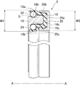
以下、添付図面を参照しつつ、本発明の実施形態によるシール構造について説明する。図1は、本発明の実施形態によるシール構造の未装着状態の構造を示す断面図である。また、図2は、本発明の実施形態によるシール構造のバルブへの装着状態を概略的に示す概略部分断面図である。更に、図3は、図2に示す本発明の実施形態によるシール構造2の装着部分を示すB部分の拡大断面図である。
Hereinafter, a seal structure according to an embodiment of the present invention will be described with reference to the accompanying drawings. FIG. 1 is a cross-sectional view showing a structure of a seal structure in an unmounted state according to an embodiment of the present invention. FIG. 2 is a schematic partial cross-sectional view schematically showing a state where the seal structure according to the embodiment of the present invention is attached to a valve. 3 is an enlarged cross-sectional view of a portion B showing a mounting portion of the
図1に示す本発明の実施形態によるシール構造2は、図2に示すバルブ1に装着することができる。以下、図1に示すシール構造2をバルブ1に装着する場合について説明するが、シール構造2は、バルブ1に限らず、流体をシールする必要のある他の装置にも用いることができることは言うまでもない。
The
まず、図1に示す本発明の実施形態によるシール構造2を装着可能なバルブ1の構造について、図2を参照しつつ説明する。図2に示すバルブ1は、流体の導管(図示せず)に接続され、この導管内で圧送される気体または液体の流体Fの流出、閉止及び流出量の調節等を行うためのボールバルブである。なお、図2は、バルブ1の断面のうち、バルブ1の中心軸線A−Aに対して上側且つ流体Fの流入口1a側の部分のみを示し、全体構造は省略されているが、基本的に中心軸線A−Aに対して対称形とされている。
First, the structure of the valve 1 to which the
図2に示す、バルブ1の流入口1a及び流出口(図示せず)のそれぞれは、流体Fを圧送する導管(図示せず)に接続される。バルブ1の内部には、導管と流体連通する流路4が形成されたハウジング6と、このハウジング6内に配置され、流路4を開閉するボール弁体8と、ハウジング6内に配置され、ボール弁体8を所定位置に支持するバルブシート10と、バルブシート10とハウジング6との間に介在され、バルブシート10をボール弁体8に対して付勢する支持ばね12とを有する。支持ばね12は圧縮コイルばねである。
Each of the
バルブシート10とハウジング6との間には、遊び空間14が形成されており、ボール弁体8が所定位置に位置決めされるように、バルブシート10はハウジング6に対して相対的に移動可能である。ハウジング6の内面と、それに対向するバルブシート10の外面とにそれぞれ段部が形成されており、それら段部の間に形成された空間11に支持ばね12が装着されており、バルブシート10は、支持ばね12によってボール弁体8に対して付勢されている。
A
バルブ1の流入口1aの近傍において、バルブシート10の外面10aと、それに対向するハウジング6の内面6aのそれぞれに、中心軸線A−Aの周りに段部が形成されおり、それらの間の隙間Gに、シール構造2が配置されている。より詳細には、上記隙間Gは、ハウジング6側のハウジング面6bと、それに対向するバルブシート10側のバルブシート面10bとの間に形成されており、ハウジング面6bとバルブシート面10bとの間から、高圧の流体Fが低圧側の外気側空間11に漏洩しないように、これらの間にシール構造2が配置されて、これらの間が密封されている。図2においては、シール構造2の円環の中心から半径方向に沿って切った一つの断面を示している(図1及び図3も同様)が、上記隙間Gは中心軸線A−Aを中心とする円環状であり、また、シール構造2は中心軸線A−Aを中心とする円環状である。
In the vicinity of the
流体Fは極低温の流体であってもよく、例えば、液体窒素(約−196℃)、液化天然ガス(−162℃)、エチレン(約−169.2℃)等の化学薬品の液体(−162℃)であってもよい。 The fluid F may be a cryogenic fluid, for example, a liquid of chemicals such as liquid nitrogen (about −196 ° C.), liquefied natural gas (−162 ° C.), ethylene (about −169.2 ° C.) (− 162 ° C.).
つぎに、図1を参照しつつ、シール構造2について詳細に説明する。
なお、本願において、「内側」は、中心軸線A−A(図2参照)に向かう方向D1(図3参照)を意味し、「外側」は、中心軸A−A(図2参照)から遠ざかる方向D2(図3参照)を意味する。また、「高圧側」は、装着状態において、本発明のシール構造2に対して流体Fの高圧側に向かう方向D3(図3参照)を意味し、「低圧側」は、本発明のシール構造2に対して高圧側とは反対側の低圧側に向かう外部方向D4(図3参照)を意味している。また、「軸線方向」は、中心軸線A−Aと並行な方向を意味する。更に、「径方向」は、中心軸線A−Aを中心とする円の径の方向を意味する。
Next, the
In the present application, “inner side” means a direction D1 (see FIG. 3) toward the central axis AA (see FIG. 2), and “outer side” moves away from the central axis AA (see FIG. 2). It means the direction D2 (see FIG. 3). The “high pressure side” means a direction D3 (see FIG. 3) toward the high pressure side of the fluid F with respect to the
図1に示すように、シール構造2は、互いに対向する面の間の隙間Gをシールするシール部材16と、シール部材16の変形を抑制する第1変形抑制部18及び第2変形抑制部20と、シール部材16をシールすべき面に対して付勢する第1ばね22及び第2ばね24とを備えている。シール構造2全体は円環状である。すなわち、それを構成するシール部材16、第1変形抑制部18及び第2変形抑制部20は円環状であり、また、第1ばね22及び第2ばね24は円環状に延びるコイルばねである。
As shown in FIG. 1, the
図1に示すように、シール構造2の断面において、シール部材16は、シールすべき第1の面(後述するように、図2及び図3に示すバルブ1に装着した場合には、ハウジング面6b)に沿って延びて、これをシールする第1シール端部16aと、第1の面に対向する第2の面(後述するように、バルブ1に装着した場合には、バルブシート面10b)に沿って延びて、これをシールする第2シール端部16bと、第1シール端部16aと第2シール端部16bとの間に延びる中間部16cとを有している。シール部材16は、第1シール端部16a、中間部16c、及び第2シール端部16bで全体が一体の略コの字形状に形成されている。この略コの字形状のシール部材16の内方に内部空間Sが形成されており、この内部空間Sに第1変形抑制部18、第1ばね22及び第2ばね24が配置されている。なお、シール部材16の断面形状は、略コの字形状(一方だけが開放した形状を意味し、湾曲したC字形状等を含む)の他、少なくとも高圧側の一方が開放した形状であれば良く、中間部16cが直線的に延びる形状に限定されず、例えば中間部16cから低圧側に向かって突出するような突起が形成されていてもよく、低圧側において他のいかなる形状であってもよい。このシール部材16は、樹脂材料により形成されている。図1と図3とを対比すると分かるように、未装着状態におけるシール部材16の径方向における幅寸法W1は、シールすべき隙間Gの幅寸法W2よりも大きくされている。
As shown in FIG. 1, in the cross section of the
上記シール部材16を形成する樹脂材料は、低温においてもシール性能を発揮できる適度な柔軟性を有したものであればよく、例えば、PTFE(ポリテトラフルオロエチレン)材料、PCTFE(ポリクロロトリフルオロエチレン)材料、ターコンT01(登録商標)材料等であってもよい。より詳細には、PTFE材料は、約−254℃〜約232℃、また、PCTFE材料は、約−254℃〜約177℃、更に、ターコンT01(登録商標)材料は約−254℃〜約232℃の温度範囲において使用することができる。更に、これらの樹脂材料は耐化学薬品性を有し、流体Fが、例えばエチレン等の化学薬品であっても、シール材として使用することができる。また、PTFE(ポリテトラフルオロエチレン)材料の線膨張係数は、10.0(10-5/℃)、PCTFE(ポリクロロトリフルオロエチレン)材料の線膨張係数は、6.0(10-5/℃)、ターコンT01(登録商標)材料のそれぞれの線膨張係数は、10.0(10-5/℃)である。
The resin material for forming the sealing
第1変形抑制部18は、略コの字形のシール部材16の内部空間Sに受け入れられており、シール部材16を内方から支持する中央芯部を構成している。第1変形抑制部18と第1シール端部16aとの間、及び第1変形抑制部18と第2シール端部16bとの間のそれぞれに、第1ばね22と第2ばね24とが配置されている。より詳細には、第1変形抑制部18は全体が環状であり、その断面は略矩形または略長方形形状をなしている。第1変形抑制部18の内側面及び外側面のそれぞれには、第1ばね22の内側部分及び第2ばね24の外側部分を着座させる凹部18b、18cが形成されている。これによって、第1ばね22及び第2ばね24が、シール部材16の空間S内で、第1シール端部16a、第2シール端部16b及び第1変形抑制部18に対して相対移動するのが防止される。また、第1変形抑制部18は中間部16cの内面16dと当接する当接面18a(装着状態では低圧側の面)を有する。
The first
第1ばね22は環状のコイルばねであり、環形状の第1変形抑制部18の凹部18bに沿って中心軸線A−Aの周りに延びている。同様に、第2ばね24は環状のコイルばねであり、環状形の第1変形抑制部18の凹部18cに沿って、中心軸線A−Aの周りに延びている。第1ばね22及び第2ばね24には、螺旋形状のヘリカルスプリングが使用されるが、シール部材16の第1シール端部16aをシールすべき第1の面(バルブ1の場合はハウジング面6b)に対して、また、第2シール端部16bをシールすべき第2の面(バルブ1の場合にはバルブシート面10b)に対して付勢可能ないかなる付勢手段であってもよく、例えば、スラントコイルスプリング、V−スプリング等のスプリングを使用してもよい。また、第1ばね22及び第2ばね24は低温下で使用でき、耐腐食性、及び耐化学薬品性を有している材料で形成されており、例えば、ステンレス鋼、ハステロイ(登録商標)合金、エルジロイ(登録商標)等により形成されている。
The
第2変形抑制部20は、断面において、径方向における幅寸法W3はシールすべき隙間Gの径方向における幅寸法W2(バルブ1の場合には図3に示す隙間Gの幅)と同じ、又は好ましくは若干小さい寸法とされる。図1に示すように、第2変形抑制部20は、中間部16cの第1変形抑制部18とは反対側に、シール部材16の中間部16cの外面16f(装着状態では低圧側の面)を囲むように配置されている。より詳細には、第2変形抑制部20は、中間部16cの外面16fと当接する外側壁部20bと、中間部16cの内側面16gと当接する内側壁部20cと、中間部16cの中間部外方面16eと当接する中間壁部20aとを備えている。第2変形抑制部20は、外側壁部20b、内側壁部20c、及び中間壁部20aが一体で、略コの字形状の断面をなすように形成されている。第2変形抑制部20の外側壁部20bが、略コの字形のシール部材16の中間部16cを受入れて、外側面16fの外側を覆っており、シール部材16の中間部16cは、第2変形抑制部20と第1変形抑制部18とによって挟持されている。シール部材16の第1シール端部16aと第2シール端部16bは、第2変形抑制部20の外へと延びている。
In the cross section of the second
さらに、第2変形抑制部20の内側壁部20cと対向する面である、シール部材16の中間部16cの内側面16gには凹部16hが形成され、一方、内側壁部20cには、この凹部16hの中に向けて突出し、凹部16hに対して係止するロック部20dが設けられている。これによって、シール部材16が第2変形抑制部20に対してロックされ、ハウジング6のハウジング面6bと第1シール端部16aとの摺動摩擦、及び/又はバルブシート10のバルブシート面10bと第2シール端部16bとの摺動摩擦により、シール部材16が第2変形抑制部20から離脱することを防ぐことができる。
Further, a
第1変形抑制部18及び第2変形抑制部20はいずれも、金属により形成され、その第1変形抑制部18の線膨張係数が、シール部材16を形成する樹脂材料の線膨張係数よりも低い金属で形成され、より詳細には、第1変形抑制部18及び第2変形抑制部20の線膨張係数は、シール部材16を形成する樹脂材料の線膨張係数よりも低い金属により形成されており、例えば、銅、ステンレス、ブラス、アルミブロンズ等で形成されている。銅、ステンレス、ブラス、アルミブロンズのそれぞれの線膨張係数は、1.6、1.4、1.8、1.6(10-5/℃)である。第1変形抑制部18及び第2変形抑制部20は、好ましくは、シール部材16の樹脂材料の線膨張係数に対して3分の1以下の線膨張係数を有する金属で形成され、また、好ましくは、シール部材16の樹脂材料の線膨張係数に対して6分の1以下の線膨張係数を有する金属で形成され、さらに好ましくは、第1変形抑制部18及び第2変形抑制部20は、樹脂材料(例えばPTFE材料)の線膨張係数に対して7分の1以下の線膨張係数を有する金属(例えばステンレス)で形成されてもよい。さらに、例えば、シール部材16のPCTFE材料の線膨張係数に対しては3分の1以下の線膨張係数を有する金属で形成され、また、例えば、シール部材16のPTFE材料の線膨張係数に対しては10分の1以下の線膨張係数を有する金属で形成されてもよい。従って、第1変形抑制部18及び第2変形抑制部20は、低温の流体によりそれ自体の温度が低下する場合においても、それ自体の寸法・体積の変化が、シール部材16よりも比較的小さくされている。すなわち、温度が常温から低温まで変化する場合において、第1変形抑制部18及び第2変形抑制部20は、シール部材に比べて、収縮変形する割合が比較的低く、変形しにくくなっている。したがって、第1変形抑制部18及び第2変形抑制部20によって、シール部材16の各部が温度及び圧力等による変形を効果的に抑制することができ、特に低温状態でも、シール構造2のシール性能を維持できる。
The first
次に、図1に示すシール構造2の、図2及び図3に示すバルブ1の隙間Gへの装着について説明する。
Next, the mounting of the
図1に示すシール構造2は、図2及び図3に示すように、バルブ1の隙間Gの互いに対向するハウジング面6bとバルブシート面10bとの間に、コの字形状のシール部材16の開放側が、流体Fの高圧側に配向されるように装着される。具体的には、シール構造2を隙間G内に装着する際には、図2及び図3に示すように、バルブシート10の段部10bの低圧側の面に当接するように装着し、使用中は、高圧の流体Fの圧力により、その位置に保持される。
As shown in FIGS. 2 and 3, the
図1を見てわかるように、未装着状態におけるシール部材16の径方向における幅寸法W1は、隙間Gの幅寸法W2よりも大きくされており、図3に示すように、シール構造2を隙間Gに装着したとき、第1ばね22及び第2ばね24が圧縮されて、シール部材16の第1シール端部16a及び第2シール端部16bがそれぞれ、ハウジング面6bとバルブシート面10bに対して付勢される。
As can be seen from FIG. 1, the width dimension W1 in the radial direction of the
第2変形抑制部20は、断面において、径方向における幅寸法W3は、シールすべき隙間Gの径方向における幅寸法W2より若干小さい寸法とされている(図3を参照)。これによって、第2変形抑制部20は、互いに相対移動可能なハウジング面6bとバルブシート面10bとの間で軸線方向に摺動可能であり、シール構造2を隙間Gの間への装着が容易であると共に、これらの面の相対平行移動が許容される。
In the cross section of the second
上述した本発明の一実施形態によるシール構造の作用効果を説明する。
シール部材16を形成するPTFE材料又はPCTFE材料は、例えば約−196℃の流体が流れる低温状態においてもシール性能を発揮できる程度の柔らかさを保ち、且つ耐化学薬品性を有する点でシール部材16に適している。一方、これらの樹脂材料の線膨張係数はそれぞれ、PTFE材料が10.0(10-5/℃)、また、PCTFE材料が6.0(10-5/℃)であり、比較的大きい値であるので、低温において収縮変形が比較的大きい。本発明においては、シール部材16がPTFE材料又はPCTFE材料等で形成されているので、常温状態だけでなく、流体Fが低温、特に約−196℃のような超低温状態においても、硬化しにくく、良好なシール性能、更には、対化学薬品性能を発揮できるシール構造2を提供することができる。
The operational effects of the above-described seal structure according to the embodiment of the present invention will be described.
The PTFE material or PCTFE material forming the
また、シール構造2においては、シール部材16が第1変形抑制部18と第2変形抑制部20とによって保持されることにより、温度状態に限定されず、常温状態から低温状態、特に低温状態においても、シール部材16の形状が第1変形抑制部18及び第2変形抑制部20により維持され、特に、低温でも良好なシール能力を発揮できるシール構造2を提供することができる。すなわち、シール構造2がハウジング面6bとバルブシート面10bとの間をシールする場合に、流体の温度による温度変化による変形が比較的少ない第1変形抑制部18が第1シール端部16a及び第2シール端部16bとの間に配置されているので、温度状態によらず、第1シール端部16aのハウジング面6bに対する、また、第2シール端部16bのバルブシート面10bに対する当接が維持され、良好にシール状態を維持することができ、流体の漏洩を抑制することができる。さらに、本発明によれば、第2変形抑制部20により、特に、低温状態において、シール部材16全体の内側への収縮変形が抑制され、シール部材16がバルブシート10へ「抱き付く」のを防止することができ、外側の第1シール端部16aのハウジング面6bに対する当接が維持されるので、低温状態でも良好にシール状態を維持することができ、流体の漏洩を抑制することができる。
In the
更に、シール構造2においては、シール部材16の中間部16cが、第1変形抑制部18と第2変形抑制部20との間に挟持されていることにより、シール部材の常温時の形状(本実施例では略コの字形状)を維持することができ、よって、良好にシール状態を維持することができ、流体の漏洩を抑制することができる。
Furthermore, in the
更に、シール構造2においては、シール部材16が第2変形抑制部20に対してロックされるので、ハウジング6のハウジング面6bと第1シール端部16aとの摺動摩擦、及び/又はバルブシート10のバルブシート面10bと第2シール端部16bとの摺動摩擦により、シール部材16が第2変形抑制部20から離脱するのを防止することができる。
Furthermore, in the
更に、シール構造2においては、ハウジング面6bと、バルブシート面10bとが相対移動する場合においても、第2変形抑制部20がハウジング面6b及びバルブシート面10bとの相対移動を許容するので、第2変形抑制部20とハウジング面6b及びバルブシート面10bとの間の磨耗を防ぐことができる。さらに、本発明のシール構造2によれば、シール部材16を環状の隙間に容易に装着することができる。
Further, in the
1 バルブ
2 シール構造
4 流路
6 ハウジング
6c ハウジング面
10 バルブシート
10c バルブシート面
16 シール部材
16a 第1シール端部
16b 第2シール端部
16c 中間部
16h 凹部
18 第1変形抑制部
20 第2変形抑制部
20d ロック部
D1 内側
D2 外側
D3 高圧側
D4 低圧側
F 流体
A−A 中心軸線
DESCRIPTION OF SYMBOLS 1
Claims (5)
上記第1の面に沿って延びる第1シール端部と、上記第2の面に沿って延びる第2シール端部と、上記第1シール端部と上記第2シール端部との間に空間が形成されるように、上記第1シール端部と上記第2シール端部との間に延びる中間部とを含む樹脂材料製のシール部材と、
上記空間内に配置された、上記シール部材の変形を抑制するための第1の金属で形成された第1変形抑制部材と、
この第1変形抑制部材と上記第1シール端部との間、及び上記第1変形抑制部材と上記第2シール端部との間のそれぞれに配置された、上記第1シール端部を第1の面に対して、また、上記第2シール端部を上記第2の面に対して付勢するためのばね部材とを有し、
上記第1の金属の線膨張係数は、上記樹脂材料の線膨張係数よりも低い、ことを特徴とするシール構造。 A seal structure for sealing a gap between a first surface of a first machine component and a second surface of a second machine component facing the first surface,
A first seal end extending along the first surface, a second seal end extending along the second surface, and a space between the first seal end and the second seal end. A seal member made of a resin material including an intermediate portion extending between the first seal end portion and the second seal end portion;
A first deformation suppressing member formed of a first metal for suppressing deformation of the seal member, disposed in the space;
The first seal end portion disposed between the first deformation suppression member and the first seal end portion and between the first deformation suppression member and the second seal end portion is defined as the first seal end portion. And a spring member for urging the second seal end against the second surface,
The seal structure according to claim 1, wherein a linear expansion coefficient of the first metal is lower than a linear expansion coefficient of the resin material.
シール構造は更に、上記中間部の外面を囲み、上記中間部の変形を抑制するための第2変形抑制部材を備えており、上記第2変形抑制部材は上記隙間の幅寸法より小さい幅寸法を有し、この第2変形抑制部材は第2の金属で形成されており、この第2の金属の線膨張係数は、上記樹脂材料の線膨張係数よりも低い、ことを特徴とする請求項1に記載のシール構造。 The seal member is substantially U-shaped with the first seal end, the second seal end, and the intermediate portion;
The seal structure further includes a second deformation suppressing member for enclosing the outer surface of the intermediate portion and suppressing deformation of the intermediate portion, and the second deformation suppressing member has a width dimension smaller than the width dimension of the gap. The second deformation suppressing member is formed of a second metal, and the linear expansion coefficient of the second metal is lower than the linear expansion coefficient of the resin material. The seal structure described in 1.
Priority Applications (2)
| Application Number | Priority Date | Filing Date | Title |
|---|---|---|---|
| JP2013242031A JP2015102132A (en) | 2013-11-22 | 2013-11-22 | Seal structure |
| CN201310714334.0A CN104653813A (en) | 2013-11-22 | 2013-12-20 | Sealing construction |
Applications Claiming Priority (1)
| Application Number | Priority Date | Filing Date | Title |
|---|---|---|---|
| JP2013242031A JP2015102132A (en) | 2013-11-22 | 2013-11-22 | Seal structure |
Publications (1)
| Publication Number | Publication Date |
|---|---|
| JP2015102132A true JP2015102132A (en) | 2015-06-04 |
Family
ID=53245276
Family Applications (1)
| Application Number | Title | Priority Date | Filing Date |
|---|---|---|---|
| JP2013242031A Pending JP2015102132A (en) | 2013-11-22 | 2013-11-22 | Seal structure |
Country Status (2)
| Country | Link |
|---|---|
| JP (1) | JP2015102132A (en) |
| CN (1) | CN104653813A (en) |
Cited By (5)
| Publication number | Priority date | Publication date | Assignee | Title |
|---|---|---|---|---|
| EP3312482A1 (en) * | 2016-10-24 | 2018-04-25 | Bal Seal Engineering, Inc. | Seal assemblies for extreme temperatures and related methods |
| CN110307336A (en) * | 2019-07-09 | 2019-10-08 | 北京裕泰行新材料科技有限公司 | Bilateral sealing device |
| WO2021002140A1 (en) * | 2019-07-04 | 2021-01-07 | Qublock Technology株式会社 | Ball valve |
| JP2021510669A (en) * | 2018-01-16 | 2021-04-30 | サン−ゴバン グラス フランス | Insulation glazing and its manufacturing method |
| CN112771292A (en) * | 2019-09-06 | 2021-05-07 | 三菱重工业株式会社 | Sealing mechanism |
Families Citing this family (2)
| Publication number | Priority date | Publication date | Assignee | Title |
|---|---|---|---|---|
| JP6254981B2 (en) * | 2015-08-12 | 2017-12-27 | ファナック株式会社 | Laser oscillator vacuum vessel |
| CN105508649A (en) * | 2016-02-01 | 2016-04-20 | 无锡智能自控工程股份有限公司 | Fixed ball valve elastic-compensation soft seal valve seat structure |
Family Cites Families (5)
| Publication number | Priority date | Publication date | Assignee | Title |
|---|---|---|---|---|
| GB9706172D0 (en) * | 1997-03-25 | 1997-05-14 | Crane John Uk Ltd | Improvements in and relating to spring energised plastic seals |
| US5992856A (en) * | 1997-12-12 | 1999-11-30 | Bal Seal Engineering Company, Inc. | Rotary, reciprocating seals with double spring and separating band rings |
| EP1461548A4 (en) * | 2001-04-18 | 2007-03-14 | Bal Seal Engineering Co | Self contained anti-blowout seal for fluids or gases |
| JP5717662B2 (en) * | 2012-01-27 | 2015-05-13 | 三菱電線工業株式会社 | Metal seal |
| CN102748495A (en) * | 2012-07-18 | 2012-10-24 | 嘉士凯(苏州)阀门配件有限公司 | Valve used in ultra-low temperature working condition |
-
2013
- 2013-11-22 JP JP2013242031A patent/JP2015102132A/en active Pending
- 2013-12-20 CN CN201310714334.0A patent/CN104653813A/en active Pending
Cited By (11)
| Publication number | Priority date | Publication date | Assignee | Title |
|---|---|---|---|---|
| EP3312482A1 (en) * | 2016-10-24 | 2018-04-25 | Bal Seal Engineering, Inc. | Seal assemblies for extreme temperatures and related methods |
| US10520092B2 (en) | 2016-10-24 | 2019-12-31 | Bal Seal Engineering, Inc. | Seal assemblies for extreme temperatures and related methods |
| JP2021510669A (en) * | 2018-01-16 | 2021-04-30 | サン−ゴバン グラス フランス | Insulation glazing and its manufacturing method |
| JP7011069B2 (en) | 2018-01-16 | 2022-02-10 | サン-ゴバン グラス フランス | Insulation glazing and its manufacturing method |
| US11441351B2 (en) | 2018-01-16 | 2022-09-13 | Saint-Gobain Glass France | Insulating glazing and method for producing same |
| WO2021002140A1 (en) * | 2019-07-04 | 2021-01-07 | Qublock Technology株式会社 | Ball valve |
| JP2021011885A (en) * | 2019-07-04 | 2021-02-04 | Qublock Technology株式会社 | Ball valve |
| JP7262764B2 (en) | 2019-07-04 | 2023-04-24 | Qublock Technology株式会社 | Ball valve |
| CN110307336A (en) * | 2019-07-09 | 2019-10-08 | 北京裕泰行新材料科技有限公司 | Bilateral sealing device |
| CN112771292A (en) * | 2019-09-06 | 2021-05-07 | 三菱重工业株式会社 | Sealing mechanism |
| CN112771292B (en) * | 2019-09-06 | 2022-12-27 | 三菱重工业株式会社 | Sealing mechanism |
Also Published As
| Publication number | Publication date |
|---|---|
| CN104653813A (en) | 2015-05-27 |
Similar Documents
| Publication | Publication Date | Title |
|---|---|---|
| JP2015102132A (en) | Seal structure | |
| US8240672B2 (en) | Low breakout friction energized gasket | |
| US10428957B2 (en) | Dynamic valve seal having retaining features | |
| JP6388884B2 (en) | Diaphragm valve with two-point seal and floating diaphragm web | |
| JP5514125B2 (en) | Dynamic sealing | |
| JP6336030B2 (en) | Graphite / metal valve seal assembly for high temperature control valves | |
| US20160153415A1 (en) | Dynamic valve seal arrangement | |
| WO2015141643A1 (en) | Switching valve | |
| CN110410574B (en) | Actuator bushing with integral seal | |
| KR100599410B1 (en) | Pressurized metal seated butterfly valve | |
| US20190226596A1 (en) | Regulating overtravel in bi-furcated plugs for use in valve assemblies | |
| WO2014147915A1 (en) | Leakage prevention seal, and pump for nuclear reactor cooling material | |
| CN110778738A (en) | High-sulfur-resistance nickel-based alloy ball valve | |
| JP6738741B2 (en) | Lining type butterfly valve | |
| US11466779B2 (en) | Seal, in particular for a rotary ball valve fitting | |
| JP7281175B2 (en) | valve | |
| JP5126462B2 (en) | Fuel cell seal structure | |
| RU2551254C2 (en) | Valve with metal gasket | |
| CN110617332B (en) | Electric valve and refrigeration cycle system | |
| WO2019111629A1 (en) | Relief valve | |
| JP7195433B2 (en) | valve | |
| Lamb | Metal seals for critical valve applications | |
| CN111853256A (en) | Sealing gland for butterfly valve | |
| JP2016109218A (en) | High-pressure gas seal structure | |
| JP2014043907A (en) | Shaft seal |