JP7010810B2 - connector - Google Patents
connector Download PDFInfo
- Publication number
- JP7010810B2 JP7010810B2 JP2018237973A JP2018237973A JP7010810B2 JP 7010810 B2 JP7010810 B2 JP 7010810B2 JP 2018237973 A JP2018237973 A JP 2018237973A JP 2018237973 A JP2018237973 A JP 2018237973A JP 7010810 B2 JP7010810 B2 JP 7010810B2
- Authority
- JP
- Japan
- Prior art keywords
- jacket
- inner housing
- housing
- electric wires
- crimping portion
- Prior art date
- Legal status (The legal status is an assumption and is not a legal conclusion. Google has not performed a legal analysis and makes no representation as to the accuracy of the status listed.)
- Active
Links
Images


Classifications
-
- H—ELECTRICITY
- H01—ELECTRIC ELEMENTS
- H01R—ELECTRICALLY-CONDUCTIVE CONNECTIONS; STRUCTURAL ASSOCIATIONS OF A PLURALITY OF MUTUALLY-INSULATED ELECTRICAL CONNECTING ELEMENTS; COUPLING DEVICES; CURRENT COLLECTORS
- H01R4/00—Electrically-conductive connections between two or more conductive members in direct contact, i.e. touching one another; Means for effecting or maintaining such contact; Electrically-conductive connections having two or more spaced connecting locations for conductors and using contact members penetrating insulation
- H01R4/10—Electrically-conductive connections between two or more conductive members in direct contact, i.e. touching one another; Means for effecting or maintaining such contact; Electrically-conductive connections having two or more spaced connecting locations for conductors and using contact members penetrating insulation effected solely by twisting, wrapping, bending, crimping, or other permanent deformation
- H01R4/18—Electrically-conductive connections between two or more conductive members in direct contact, i.e. touching one another; Means for effecting or maintaining such contact; Electrically-conductive connections having two or more spaced connecting locations for conductors and using contact members penetrating insulation effected solely by twisting, wrapping, bending, crimping, or other permanent deformation by crimping
- H01R4/183—Electrically-conductive connections between two or more conductive members in direct contact, i.e. touching one another; Means for effecting or maintaining such contact; Electrically-conductive connections having two or more spaced connecting locations for conductors and using contact members penetrating insulation effected solely by twisting, wrapping, bending, crimping, or other permanent deformation by crimping for cylindrical elongated bodies, e.g. cables having circular cross-section
- H01R4/184—Electrically-conductive connections between two or more conductive members in direct contact, i.e. touching one another; Means for effecting or maintaining such contact; Electrically-conductive connections having two or more spaced connecting locations for conductors and using contact members penetrating insulation effected solely by twisting, wrapping, bending, crimping, or other permanent deformation by crimping for cylindrical elongated bodies, e.g. cables having circular cross-section comprising a U-shaped wire-receiving portion
-
- H—ELECTRICITY
- H01—ELECTRIC ELEMENTS
- H01R—ELECTRICALLY-CONDUCTIVE CONNECTIONS; STRUCTURAL ASSOCIATIONS OF A PLURALITY OF MUTUALLY-INSULATED ELECTRICAL CONNECTING ELEMENTS; COUPLING DEVICES; CURRENT COLLECTORS
- H01R13/00—Details of coupling devices of the kinds covered by groups H01R12/70 or H01R24/00 - H01R33/00
- H01R13/46—Bases; Cases
- H01R13/502—Bases; Cases composed of different pieces
-
- H—ELECTRICITY
- H01—ELECTRIC ELEMENTS
- H01R—ELECTRICALLY-CONDUCTIVE CONNECTIONS; STRUCTURAL ASSOCIATIONS OF A PLURALITY OF MUTUALLY-INSULATED ELECTRICAL CONNECTING ELEMENTS; COUPLING DEVICES; CURRENT COLLECTORS
- H01R13/00—Details of coupling devices of the kinds covered by groups H01R12/70 or H01R24/00 - H01R33/00
- H01R13/58—Means for relieving strain on wire connection, e.g. cord grip, for avoiding loosening of connections between wires and terminals within a coupling device terminating a cable
- H01R13/5804—Means for relieving strain on wire connection, e.g. cord grip, for avoiding loosening of connections between wires and terminals within a coupling device terminating a cable comprising a separate cable clamping part
- H01R13/5808—Means for relieving strain on wire connection, e.g. cord grip, for avoiding loosening of connections between wires and terminals within a coupling device terminating a cable comprising a separate cable clamping part formed by a metallic element crimped around the cable
-
- H—ELECTRICITY
- H01—ELECTRIC ELEMENTS
- H01R—ELECTRICALLY-CONDUCTIVE CONNECTIONS; STRUCTURAL ASSOCIATIONS OF A PLURALITY OF MUTUALLY-INSULATED ELECTRICAL CONNECTING ELEMENTS; COUPLING DEVICES; CURRENT COLLECTORS
- H01R13/00—Details of coupling devices of the kinds covered by groups H01R12/70 or H01R24/00 - H01R33/00
- H01R13/58—Means for relieving strain on wire connection, e.g. cord grip, for avoiding loosening of connections between wires and terminals within a coupling device terminating a cable
- H01R13/5804—Means for relieving strain on wire connection, e.g. cord grip, for avoiding loosening of connections between wires and terminals within a coupling device terminating a cable comprising a separate cable clamping part
- H01R13/5812—Means for relieving strain on wire connection, e.g. cord grip, for avoiding loosening of connections between wires and terminals within a coupling device terminating a cable comprising a separate cable clamping part the cable clamping being achieved by mounting the separate part on the housing of the coupling device
-
- H—ELECTRICITY
- H01—ELECTRIC ELEMENTS
- H01R—ELECTRICALLY-CONDUCTIVE CONNECTIONS; STRUCTURAL ASSOCIATIONS OF A PLURALITY OF MUTUALLY-INSULATED ELECTRICAL CONNECTING ELEMENTS; COUPLING DEVICES; CURRENT COLLECTORS
- H01R13/00—Details of coupling devices of the kinds covered by groups H01R12/70 or H01R24/00 - H01R33/00
- H01R13/648—Protective earth or shield arrangements on coupling devices, e.g. anti-static shielding
- H01R13/658—High frequency shielding arrangements, e.g. against EMI [Electro-Magnetic Interference] or EMP [Electro-Magnetic Pulse]
- H01R13/6581—Shield structure
-
- H—ELECTRICITY
- H01—ELECTRIC ELEMENTS
- H01R—ELECTRICALLY-CONDUCTIVE CONNECTIONS; STRUCTURAL ASSOCIATIONS OF A PLURALITY OF MUTUALLY-INSULATED ELECTRICAL CONNECTING ELEMENTS; COUPLING DEVICES; CURRENT COLLECTORS
- H01R13/00—Details of coupling devices of the kinds covered by groups H01R12/70 or H01R24/00 - H01R33/00
- H01R13/646—Details of coupling devices of the kinds covered by groups H01R12/70 or H01R24/00 - H01R33/00 specially adapted for high-frequency, e.g. structures providing an impedance match or phase match
- H01R13/6461—Means for preventing cross-talk
- H01R13/6463—Means for preventing cross-talk using twisted pairs of wires
Description
本発明は、コネクタに関する。詳細には、インナハウジングに組付けられるジャケット固定部材に複数の電線の外周を覆うジャケットを加締める加締部を有するコネクタに関する。 The present invention relates to a connector. More specifically, the present invention relates to a connector having a crimping portion for crimping a jacket covering the outer periphery of a plurality of electric wires to a jacket fixing member assembled to an inner housing.
従来、コネクタとしては、アウタハウジングとしての外部ハウジングと、外部ハウジングに収容され内部に保持されるインナハウジングとしての保持部材と、保持部材の外周に組付けられるジャケット固定部材としての上側シェルと、保持部材に収容される複数の端子と、複数の端子が端末部にそれぞれ接続され保持部材から引き出される複数の電線と、保持部材から引き出された複数の電線の外周を一括して覆うジャケットとしての外側部材と、上側シェルに設けられ外側部材の外周に加締められる加締部とを備えたものが知られている(例えば、特許文献1参照)。 Conventionally, as a connector, an outer housing as an outer housing, a holding member as an inner housing housed in the outer housing and held inside, and an upper shell as a jacket fixing member assembled on the outer periphery of the holding member are held. The outside as a jacket that collectively covers the outer circumferences of a plurality of terminals housed in the member, a plurality of electric wires to which the plurality of terminals are connected to the terminal portion and drawn out from the holding member, and a plurality of electric wires drawn out from the holding member. A member is known to have a crimping portion provided on the upper shell and crimped to the outer periphery of the outer member (see, for example, Patent Document 1).
このコネクタでは、保持部材に複数の端子を収容した状態で、保持部材の外周に上側シェルを組付け、保持部材から引き出された複数の電線の外周を一括して覆う外側部材の外周を加締部で加締めることによって、各部材の組付状態を保持することができる。 In this connector, with a plurality of terminals housed in the holding member, an upper shell is assembled on the outer periphery of the holding member, and the outer periphery of the outer member that collectively covers the outer periphery of the plurality of electric wires drawn from the holding member is crimped. By crimping at the portion, the assembled state of each member can be maintained.
ところで、上記特許文献1のようなコネクタでは、複数の電線とジャケットとが完全に密着せず、複数の電線とジャケットとの間に空間(隙間)が存在していることがある。
By the way, in a connector as in
このような場合、ジャケットの外周に加締部を加締めたとしても、複数の電線とジャケットとの間に空間が残存してしまうことがある。 In such a case, even if the crimping portion is crimped to the outer periphery of the jacket, a space may remain between the plurality of electric wires and the jacket.
複数の電線とジャケットとの間に空間が残存していると、加締部において、ジャケットが複数の電線側に逃げてしまい、ジャケットに対する加締部の保持力が低下してしまう。 If a space remains between the plurality of electric wires and the jacket, the jacket escapes to the plurality of electric wires side in the crimping portion, and the holding force of the crimping portion with respect to the jacket is lowered.
このため、複数の電線やジャケットにインナハウジングから離れる方向に引張力が加わると、加締部において、ジャケットに対する加締め位置がズレる、或いはジャケットが加締部から外れてしまう虞があった。 For this reason, if a tensile force is applied to a plurality of electric wires or jackets in a direction away from the inner housing, there is a risk that the crimping position with respect to the jacket will be displaced in the crimping portion, or the jacket will be disengaged from the crimping portion.
そこで、この発明は、ジャケットに対する加締部の保持力を向上することができるコネクタの提供を目的としている。 Therefore, an object of the present invention is to provide a connector capable of improving the holding force of the crimping portion with respect to the jacket.
請求項1記載の発明は、アウタハウジングと、前記アウタハウジングに収容され内部に保持されるインナハウジングと、前記インナハウジングの外周に組付けられるジャケット固定部材と、前記インナハウジングに収容される複数の端子と、複数の前記端子が端末部にそれぞれ接続され前記インナハウジングから引き出される複数の電線と、前記インナハウジングから引き出された複数の前記電線の外周を隙間を有して一括して覆うジャケットと、前記ジャケット固定部材に設けられ前記ジャケットの外周に加締められる加締部と、前記加締部に設けられ前記ジャケット側に向けて突出し前記ジャケットの長さ方向に対して傾斜して配置されたセレーションとを有し、前記加締部は、前記アウタハウジングの内部に配置されていることを特徴とするコネクタである。
The invention according to
このコネクタでは、加締部に、ジャケット側に向けて突出しジャケットの長さ方向に対して傾斜して配置されたセレーションが設けられているので、ジャケットの外周に加締部を加締めたときに、セレーションをジャケットの外周に食い込むように配置させることができる。 In this connector, the crimping portion is provided with serrations that protrude toward the jacket side and are arranged so as to be inclined with respect to the length direction of the jacket. , The serrations can be arranged so as to bite into the outer circumference of the jacket.
また、セレーションは、ジャケットの長さ方向に対して傾斜して配置されているので、セレーションがジャケットの長さ方向に直交して配置される場合に比較して、加締部におけるセレーションの長さを長くすることができ、ジャケットに対するセレーションの食い込み量を増大させることができる。 Further, since the serrations are arranged so as to be inclined with respect to the length direction of the jacket, the length of the serrations at the crimping portion is compared with the case where the serrations are arranged orthogonally to the length direction of the jacket. Can be lengthened, and the amount of serrations biting into the jacket can be increased.
従って、このようなコネクタでは、複数の電線とジャケットとの間に空間が残存していても、セレーションをジャケットの外周に安定して食い込ませることができ、ジャケットに対する加締部の保持力を向上することができる。 Therefore, with such a connector, even if a space remains between the plurality of electric wires and the jacket, the serrations can be stably bitten into the outer circumference of the jacket, and the holding force of the crimping portion against the jacket is improved. can do.
請求項2記載の発明は、請求項1記載のコネクタであって、前記セレーションは、突出した角部がR状に形成されていることを特徴とする。
The invention according to claim 2 is the connector according to
このコネクタでは、セレーションの突出した角部が、R状に形成されているので、複数の電線やジャケットに引張力が加わったときに、セレーションの角部によってジャケットに損傷が生じることを防止することができる。 In this connector, the protruding corners of the serrations are formed in an R shape, so that when tensile force is applied to multiple wires or jackets, the corners of the serrations prevent the jacket from being damaged. Can be done.
請求項3記載の発明は、請求項1又は2記載のコネクタであって、前記セレーションは、複数設けられていることを特徴とする。
The invention according to
このコネクタでは、セレーションが、複数設けられているので、ジャケットに対する加締部の保持力をさらに向上することができる。 Since a plurality of serrations are provided in this connector, the holding force of the crimping portion with respect to the jacket can be further improved.
本発明によれば、ジャケットに対する加締部の保持力を向上することができるコネクタを提供することができるという効果を奏する。 According to the present invention, it is possible to provide a connector capable of improving the holding force of the crimping portion with respect to the jacket.
図1~図7を用いて本発明の実施の形態に係るコネクタについて説明する。 The connector according to the embodiment of the present invention will be described with reference to FIGS. 1 to 7.
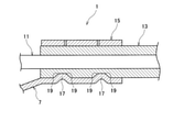
本実施の形態に係るコネクタ1は、アウタハウジング3と、アウタハウジング3に収容され内部に保持されるインナハウジング5と、インナハウジング5の外周に組付けられるジャケット固定部材7と、インナハウジング5に収容される複数の端子9と、複数の端子9が端末部にそれぞれ接続されインナハウジング5から引き出される複数の電線11と、インナハウジング5から引き出された複数の電線11の外周を一括して覆うジャケット13と、ジャケット固定部材7に設けられジャケット13の外周に加締められる加締部15とを備えている。
The
そして、加締部15には、ジャケット13側に向けて突出しジャケット13の長さ方向に対して傾斜して配置されたセレーション17が設けられている。
The crimping
また、セレーション17は、突出した角部19がR状に形成されている。
Further, in the
さらに、セレーション17は、複数設けられている。
Further, a plurality of
図1~図7に示すように、アウタハウジング3は、合成樹脂などの絶縁性材料からなり、直方体状に形成され、相手ハウジング(不図示)と嵌合可能となっている。
As shown in FIGS. 1 to 7, the
このアウタハウジング3の上部には、アウタハウジング3と連続する一部材で高さ方向に揺動可能なロックアーム21が設けられている。
A
ロックアーム21には、アウタハウジング3と相手ハウジングとが嵌合した状態で、相手ハウジングに設けられた被ロック部(不図示)に係合するロック部23が設けられている。
The
このロックアーム21は、アウタハウジング3と相手ハウジングとが嵌合するときに、ロック部23と被ロック部との摺動により下方に向けて撓まされ、アウタハウジング3と相手ハウジングとが嵌合したときに、上方に向けて復元し、ロック部23と被ロック部とが係合される。
When the
このロックアーム21のロック部23と相手ハウジングの被ロック部との係合により、アウタハウジング3と相手ハウジングとの嵌合状態が保持される。
By engaging the
なお、ロックアーム21には、押圧することによりロックアーム21を下方に向けて撓ませる操作部25が設けられ、操作部25を押圧することにより、ロック部23と被ロック部との係合が解除され、アウタハウジング3と相手ハウジングとの嵌合を解除することができる。
The
このようなアウタハウジング3の内部には、インナハウジング5を収容可能な収容部27が設けられている。
Inside such an
収容部27の内部には、アウタハウジング3の高さ方向に撓み可能な係止ランス29が設けられている。
Inside the
係止ランス29は、収容部27の長さ方向の一端側の開口から収容部27にインナハウジング5が収容されることにより、インナハウジング5及びインナハウジング5に組付けられたジャケット固定部材7と摺動して下方に向けて撓まされ、インナハウジング5が収容部27の正規収容位置に位置したとき、上方に向けて復元し、ジャケット固定部材7に係止される。
The
この係止ランス29のインナハウジング5に組付けられたジャケット固定部材7への係止により、インナハウジング5が収容部27の長さ方向の一端側の開口から抜け出ることがなく、インナハウジング5がアウタハウジング3の収容部27内に保持される。
By locking the
インナハウジング5は、合成樹脂などの絶縁性材料からなり、収容部27に収容可能な直方体状に形成されている。
The
このインナハウジング5の内部には、複数(ここでは2つ)の端子9を収容可能な複数(ここでは2つ)の端子収容室31が設けられている。
Inside the
複数の端子収容室31には、長さ方向の一端側の開口から端子9がそれぞれ収容され、インナハウジング5の外周から複数の端子収容室31に向けて組付けられる係止部材33によって、端子9の端子収容室31からの抜け止めがなされる。
The
この複数の端子収容室31にそれぞれ端子9が収容されたインナハウジング5は、アウタハウジング3の収容部27に収容された状態で、端子収容室31の長さ方向の他端側の開口側の部分と、収容部27の長さ方向の他端側の開口とが一致するように配置される。
The
このようなインナハウジング5の外周には、ジャケット固定部材7を組付けるための複数(ここでは4つ)の係合凹部35が設けられている。
A plurality of (here, four)
ジャケット固定部材7は、金属製の板材に対して、プレス加工などを施すことにより、装着部37と、加締部15とが設けられている。
The
装着部37は、インナハウジング5の底面に対向して配置される底壁39と、底壁39の両側から上方に向けて折り曲げられインナハウジング5の両側面に対向して配置される側壁41,41とを備えている。
The
装着部37の側壁41,41の内面には、インナハウジング5の複数の係合凹部35に係合される複数(ここでは4つ)の係合凸部43が設けられている。
On the inner surfaces of the
この複数の係合凹部35と複数の係合凸部43との係合により、ジャケット固定部材7が装着部37によってインナハウジング5の外周に組付けられる。
By engaging the plurality of engaging
この複数の係合凸部43が設けられた側壁41のうちアウタハウジング3への挿入方向前側に位置する側壁41には、インナハウジング5に設けられた被当接部45とアウタハウジング3からの抜け方向に対向する部分に被当接部45と当接可能な当接部47が設けられている。
Of the
この当接部47は、インナハウジング5の被当接部45と当接することにより、インナハウジング5から引き出された複数の電線11やジャケット13にインナハウジング5から離れる方向に引張力が加わったとしても、インナハウジング5に対するジャケット固定部材7の配置位置を保持することができる。
Assuming that the
加えて、装着部37の底壁39には、アウタハウジング3の係止ランス29に係止される切り起こしにより形成された係止部49が設けられており、アウタハウジング3からのジャケット固定部材7の抜け止めがなされている。
In addition, the
このような装着部37には、底壁39及び側壁41,41と連続する一部材で加締部15が設けられている。
Such a mounting
加締部15は、底壁39の両側から上方に向けて延設された一対の加締片51,51を備えている。
The crimping
この加締部15は、一対の加締片51,51が、治具などによって、インナハウジング5から引き出された複数の電線11の外周を一括して覆うジャケット13の外周に加締められる。
The crimping
このような加締部15によって加締められるジャケット13の内部に配置された複数の電線11の端末部には、複数の端子9がそれぞれ接続されている。
A plurality of
複数(ここでは2つ)の端子9は、箱状の接続部を有する雌型端子からなり、インナハウジング5の複数の端子収容室31にそれぞれ長さ方向の一端側の開口から挿入され、端子収容室31の正規位置に収容される。
The plurality of (here, two)
この複数の端子9は、アウタハウジング3が相手ハウジングと嵌合することにより、インナハウジング5の長さ方向の他端側の開口から相手ハウジングに収容された複数(ここでは2つ)の相手端子(不図示)のタブ状の接続部がそれぞれ挿入され、複数の相手端子に電気的に接続される。
The plurality of
このような複数の端子9は、複数の電線11の端末部にそれぞれ電気的に接続されている。
Such a plurality of
複数(ここでは2本)の電線11は、芯線の外周を絶縁被覆された被覆電線からなり、長さ方向の一端側が電源や機器などに電気的に接続され、長さ方向の他端側が圧着によって端子9に電気的に接続されている。
The plurality of (here, two)
この複数の電線11は、その外周がジャケット13によって一括して覆われ、端子9がインナハウジング5に収容された状態で、端子収容室31の長さ方向の一端側の開口から外部に引き出される。
The outer periphery of the plurality of
ジャケット13は、絶縁性材料からなり、筒状に形成され、インナハウジング5の外部に引き出された複数の電線11の外周を一括して覆っている。
The
なお、ジャケット13の内部には、2本の電線11が挿通されているが、この2本の電線は捻られて配置されてもよく、ジャケット13の内部に捻られて電線11が配置されたものは、ツイストペア電線と称される。
Although two
このジャケット13の複数の電線11が露出する側の端部外周には、ジャケット固定部材7の加締部15が加締められ、ジャケット13がジャケット固定部材7に固定される。
A crimping
ところで、複数の電線11とジャケット13との間には、空間(隙間)が形成されている。
By the way, a space (gap) is formed between the plurality of
複数の電線11とジャケット13との間に空間が形成されていると、ジャケット13の外周に加締部15を加締めたとしても、複数の電線11とジャケット13との間に空間が残存してしまうことがある。
When a space is formed between the plurality of
複数の電線11とジャケット13との間に空間が残存していると、加締部15において、ジャケット13が複数の電線11側に逃げてしまい、ジャケット13に対する加締部15の保持力が低下してしまう。
If a space remains between the plurality of
このため、複数の電線11やジャケット13にインナハウジング5から離れる方向に引張力が加わると、加締部15において、ジャケット13に対する加締め位置がズレる、或いはジャケット13が加締部15から外れてしまう虞があった。
Therefore, when a tensile force is applied to the plurality of
そこで、加締部15には、セレーション17が設けられている。
Therefore, the crimping
セレーション17は、加締部15のジャケット13側の表面に、一対の加締片51,51に跨って形成され、ジャケット13の長さ方向に沿って複数(ここでは2本)設けられている。
The
この複数のセレーション17は、加締部15のジャケット13と反対側を打ち出し加工などを施すことによって、それぞれジャケット13側に向けて突出され、ジャケット13の長さ方向に対して傾斜して配置されている。
The plurality of
このようなセレーション17を加締部15に設けることにより、例えば、図3,図4に示すように、加締部15において、ジャケット13と電線11との間に空間53が残存していても、ジャケット13に加締部15を加締めたときに、セレーション17をジャケット13の外周面に食い込ませることができる。
By providing such a
このため、複数の電線11やジャケット13にインナハウジング5から離れる方向に引張力が加わったとしても、加締部15にジャケット13を安定して保持することができる。
Therefore, even if a tensile force is applied to the plurality of
加えて、セレーション17は、ジャケット13の長さ方向に対して傾斜して配置されているので、セレーション17がジャケット13の長さ方向に直交して配置される場合に比較して、加締部15におけるセレーション17の長さを長くすることができ、ジャケット13に対するセレーション17の食い込み量を増大させることができる。
In addition, since the
従って、このようなセレーション17を加締部15に設けることにより、ジャケット13に対する加締部15の保持力を増大することができ、加締部15において、ジャケット13に対する加締め位置がズレる、或いはジャケット13が加締部15から外れてしまうということを防止することができる。
Therefore, by providing
ここで、セレーション17は、突出した角部19がR状に形成されている。
Here, in the
このように角部19をR状に形成することにより、複数の電線11やジャケット13にインナハウジング5から離れる方向に引張力が加わったとしても、ジャケット13の外周面に食い込んだセレーション17の角部19によって、ジャケット13が引き裂かれるなどのジャケット13の損傷を防止することができる。
By forming the
このようなコネクタ1の組付けは、まず、ジャケット13から露出する複数の電線11の端末部にそれぞれ複数の端子9を接続し、複数の端子9をインナハウジング5の複数の端子収容室31にそれぞれ収容する。
In such assembly of the
次に、インナハウジング5の複数の係合凹部35に対して、ジャケット固定部材7の装着部37に設けられた複数の係合凸部43を係合させ、ジャケット固定部材7をインナハウジング5の外周に組付ける。
Next, the plurality of engaging
次に、ジャケット固定部材7の加締部15を、治具などによって、ジャケット13の外周に加締め、ジャケット13をジャケット固定部材7に固定させる。
Next, the crimping
そして、アウタハウジング3の収容部27に、インナハウジング5を挿入し、係止ランス29をインナハウジング5に組付けられたジャケット固定部材7に係止させ、コネクタ1の組付けを完了する。
Then, the
このようなコネクタ1では、加締部15に、ジャケット13側に向けて突出しジャケット13の長さ方向に対して傾斜して配置されたセレーション17が設けられているので、ジャケット13の外周に加締部15を加締めたときに、セレーション17をジャケット13の外周に食い込むように配置させることができる。
In such a
また、セレーション17は、ジャケット13の長さ方向に対して傾斜して配置されているので、セレーション17がジャケット13の長さ方向に直交して配置される場合に比較して、加締部15におけるセレーション17の長さを長くすることができ、ジャケット13に対するセレーション17の食い込み量を増大させることができる。
Further, since the
従って、このようなコネクタ1では、複数の電線11とジャケット13との間に空間が残存していても、セレーション17をジャケット13の外周に安定して食い込ませることができ、ジャケット13に対する加締部15の保持力を向上することができる。
Therefore, in such a
また、セレーション17の突出した角部19は、R状に形成されているので、複数の電線11やジャケット13に引張力が加わったときに、セレーション17の角部19によってジャケット13に損傷が生じることを防止することができる。
Further, since the protruding
さらに、セレーション17は、複数設けられているので、ジャケット13に対する加締部15の保持力をさらに向上することができる。
Further, since a plurality of
なお、本発明の実施の形態に係るコネクタでは、セレーションが2本となっているが、これに限らず、セレーションを1本、或いは3本以上としてもよい。 The connector according to the embodiment of the present invention has two serrations, but the present invention is not limited to this, and the number of serrations may be one or three or more.
また、複数の端子と複数の電線とは、2つと2本となっているが、これに限らず、複数の端子を3つ以上、複数の電線を3本以上としてもよい。 Further, the plurality of terminals and the plurality of electric wires are two and two, but the present invention is not limited to this, and the plurality of terminals may be three or more and the plurality of electric wires may be three or more.
さらに、端子は、雌型端子となっているが、これに限らず、端子をタブ状の接続部を有する雄型端子としてもよい。 Further, the terminal is a female terminal, but the terminal is not limited to this, and the terminal may be a male terminal having a tab-shaped connection portion.
1…コネクタ
3…アウタハウジング
5…インナハウジング
7…ジャケット固定部材
9…端子
11…電線
13…ジャケット
15…加締部
17…セレーション
19…角部
1 ...
Claims (3)
前記アウタハウジングに収容され内部に保持されるインナハウジングと、
前記インナハウジングの外周に組付けられるジャケット固定部材と、
前記インナハウジングに収容される複数の端子と、
複数の前記端子が端末部にそれぞれ接続され前記インナハウジングから引き出される複数の電線と、
前記インナハウジングから引き出された複数の前記電線の外周を隙間を有して一括して覆うジャケットと、
前記ジャケット固定部材に設けられ前記ジャケットの外周に加締められる加締部と、
前記加締部に設けられ前記ジャケット側に向けて突出し前記ジャケットの長さ方向に対して傾斜して配置されたセレーションと、
を有し、
前記加締部は、前記アウタハウジングの内部に配置されていることを特徴とするコネクタ。 Outer housing and
The inner housing housed in the outer housing and held inside,
The jacket fixing member assembled on the outer circumference of the inner housing and
With a plurality of terminals housed in the inner housing,
A plurality of electric wires to which the plurality of terminals are connected to the terminal portion and drawn out from the inner housing, and a plurality of electric wires.
A jacket that collectively covers the outer circumferences of the plurality of electric wires drawn from the inner housing with a gap.
A crimping portion provided on the jacket fixing member and crimped to the outer periphery of the jacket,
Serrations provided in the crimping portion, protruding toward the jacket side and inclined with respect to the length direction of the jacket, and
Have,
The crimping portion is a connector characterized in that it is arranged inside the outer housing .
前記セレーションは、突出した角部がR状に形成されていることを特徴とするコネクタ。 The connector according to claim 1.
The serration is a connector characterized in that the protruding corners are formed in an R shape.
前記セレーションは、複数設けられていることを特徴とするコネクタ。 The connector according to claim 1 or 2.
The serration is a connector characterized in that a plurality of serrations are provided.
Priority Applications (4)
| Application Number | Priority Date | Filing Date | Title |
|---|---|---|---|
| JP2018237973A JP7010810B2 (en) | 2018-12-20 | 2018-12-20 | connector |
| CN201911280065.5A CN111355099B (en) | 2018-12-20 | 2019-12-13 | Connector with a locking member |
| EP19217454.8A EP3671959B1 (en) | 2018-12-20 | 2019-12-18 | Connector |
| US16/720,572 US20200203883A1 (en) | 2018-12-20 | 2019-12-19 | Connector |
Applications Claiming Priority (1)
| Application Number | Priority Date | Filing Date | Title |
|---|---|---|---|
| JP2018237973A JP7010810B2 (en) | 2018-12-20 | 2018-12-20 | connector |
Publications (2)
| Publication Number | Publication Date |
|---|---|
| JP2020102305A JP2020102305A (en) | 2020-07-02 |
| JP7010810B2 true JP7010810B2 (en) | 2022-01-26 |
Family
ID=68944605
Family Applications (1)
| Application Number | Title | Priority Date | Filing Date |
|---|---|---|---|
| JP2018237973A Active JP7010810B2 (en) | 2018-12-20 | 2018-12-20 | connector |
Country Status (4)
| Country | Link |
|---|---|
| US (1) | US20200203883A1 (en) |
| EP (1) | EP3671959B1 (en) |
| JP (1) | JP7010810B2 (en) |
| CN (1) | CN111355099B (en) |
Families Citing this family (2)
| Publication number | Priority date | Publication date | Assignee | Title |
|---|---|---|---|---|
| JP7404176B2 (en) | 2020-07-15 | 2023-12-25 | 矢崎総業株式会社 | wire with terminal |
| CN112888209B (en) * | 2020-12-28 | 2023-01-24 | 维沃移动通信有限公司 | Housing and electronic device |
Citations (4)
| Publication number | Priority date | Publication date | Assignee | Title |
|---|---|---|---|---|
| JP2003249284A (en) | 2002-02-25 | 2003-09-05 | Auto Network Gijutsu Kenkyusho:Kk | Crimp style terminal for aluminum wire |
| JP2016509357A (en) | 2013-03-06 | 2016-03-24 | ティーイー コネクティビティ ジャーマニー ゲゼルシャフト ミット ベシュレンクテル ハフツンクTE Connectivity Germany GmbH | Electro-crimp contact device |
| JP2016149344A (en) | 2015-01-19 | 2016-08-18 | ティーイー コネクティビティ ジャーマニー ゲゼルシャフト ミット ベシュレンクテル ハフツンクTE Connectivity Germany GmbH | Connector insert and connector for data transmission in automobile |
| JP2017143028A (en) | 2016-02-12 | 2017-08-17 | 古河電気工業株式会社 | Female terminal and wiring harness with the same |
Family Cites Families (7)
| Publication number | Priority date | Publication date | Assignee | Title |
|---|---|---|---|---|
| JPS6114477U (en) * | 1984-06-29 | 1986-01-28 | 株式会社 ジヨイン | connector |
| JPH0668916A (en) * | 1992-08-21 | 1994-03-11 | Matsushita Electric Works Ltd | Wire connecting device |
| US6257920B1 (en) * | 1999-06-25 | 2001-07-10 | Itt Manufacturing Enterprises, Inc. | Cable retention clip |
| JP5071288B2 (en) * | 2008-07-22 | 2012-11-14 | 住友電装株式会社 | Terminal fittings and wires with terminal fittings |
| JP2011216253A (en) * | 2010-03-31 | 2011-10-27 | Yazaki Corp | Crimp terminal and wire connection structure of crimp terminal |
| WO2017122779A1 (en) * | 2016-01-13 | 2017-07-20 | 株式会社オートネットワーク技術研究所 | Connector |
| JP6647958B2 (en) | 2016-05-09 | 2020-02-14 | 日本航空電子工業株式会社 | connector |
-
2018
- 2018-12-20 JP JP2018237973A patent/JP7010810B2/en active Active
-
2019
- 2019-12-13 CN CN201911280065.5A patent/CN111355099B/en active Active
- 2019-12-18 EP EP19217454.8A patent/EP3671959B1/en active Active
- 2019-12-19 US US16/720,572 patent/US20200203883A1/en not_active Abandoned
Patent Citations (4)
| Publication number | Priority date | Publication date | Assignee | Title |
|---|---|---|---|---|
| JP2003249284A (en) | 2002-02-25 | 2003-09-05 | Auto Network Gijutsu Kenkyusho:Kk | Crimp style terminal for aluminum wire |
| JP2016509357A (en) | 2013-03-06 | 2016-03-24 | ティーイー コネクティビティ ジャーマニー ゲゼルシャフト ミット ベシュレンクテル ハフツンクTE Connectivity Germany GmbH | Electro-crimp contact device |
| JP2016149344A (en) | 2015-01-19 | 2016-08-18 | ティーイー コネクティビティ ジャーマニー ゲゼルシャフト ミット ベシュレンクテル ハフツンクTE Connectivity Germany GmbH | Connector insert and connector for data transmission in automobile |
| JP2017143028A (en) | 2016-02-12 | 2017-08-17 | 古河電気工業株式会社 | Female terminal and wiring harness with the same |
Also Published As
| Publication number | Publication date |
|---|---|
| EP3671959B1 (en) | 2021-09-01 |
| CN111355099A (en) | 2020-06-30 |
| US20200203883A1 (en) | 2020-06-25 |
| JP2020102305A (en) | 2020-07-02 |
| CN111355099B (en) | 2021-09-28 |
| EP3671959A1 (en) | 2020-06-24 |
Similar Documents
| Publication | Publication Date | Title |
|---|---|---|
| JP6882941B2 (en) | Coaxial connector assembly | |
| JP2009170289A (en) | Wire harness and wire harness assembly method | |
| JP7010810B2 (en) | connector | |
| JP5565946B2 (en) | connector | |
| CN113196585A (en) | Connector and connector structure | |
| JP6940345B2 (en) | connector | |
| JP2010157367A (en) | Electrical connector | |
| JP6599149B2 (en) | connector | |
| JP6356504B2 (en) | connector | |
| JP6641320B2 (en) | connector | |
| JP2014078507A (en) | Contact for latching in contact chamber of plug connection element and plug connection element | |
| JP6904794B2 (en) | Connecting terminal | |
| JP4871628B2 (en) | connector | |
| JP2017142978A (en) | Connection terminal | |
| JP4541999B2 (en) | Shielded connector | |
| JP6175417B2 (en) | connector | |
| JP7092812B2 (en) | Connecting terminal | |
| JP7461225B2 (en) | Terminal connection structure | |
| JP7351687B2 (en) | connector | |
| JP2018156764A (en) | connector | |
| JP6865075B2 (en) | connector | |
| WO2019167617A1 (en) | Connector | |
| JP6839609B2 (en) | connector | |
| JP2017147062A (en) | connector | |
| JP2021051852A (en) | connector |
Legal Events
| Date | Code | Title | Description |
|---|---|---|---|
| A621 | Written request for application examination |
Free format text: JAPANESE INTERMEDIATE CODE: A621 Effective date: 20200219 |
|
| A977 | Report on retrieval |
Free format text: JAPANESE INTERMEDIATE CODE: A971007 Effective date: 20201225 |
|
| A131 | Notification of reasons for refusal |
Free format text: JAPANESE INTERMEDIATE CODE: A131 Effective date: 20210202 |
|
| A521 | Request for written amendment filed |
Free format text: JAPANESE INTERMEDIATE CODE: A523 Effective date: 20210308 |
|
| A131 | Notification of reasons for refusal |
Free format text: JAPANESE INTERMEDIATE CODE: A131 Effective date: 20210817 |
|
| A521 | Request for written amendment filed |
Free format text: JAPANESE INTERMEDIATE CODE: A523 Effective date: 20210917 |
|
| A131 | Notification of reasons for refusal |
Free format text: JAPANESE INTERMEDIATE CODE: A131 Effective date: 20211019 |
|
| TRDD | Decision of grant or rejection written | ||
| A01 | Written decision to grant a patent or to grant a registration (utility model) |
Free format text: JAPANESE INTERMEDIATE CODE: A01 Effective date: 20220111 |
|
| A61 | First payment of annual fees (during grant procedure) |
Free format text: JAPANESE INTERMEDIATE CODE: A61 Effective date: 20220113 |
|
| R150 | Certificate of patent or registration of utility model |
Ref document number: 7010810 Country of ref document: JP Free format text: JAPANESE INTERMEDIATE CODE: R150 |
|
| S531 | Written request for registration of change of domicile |
Free format text: JAPANESE INTERMEDIATE CODE: R313531 |
|
| R350 | Written notification of registration of transfer |
Free format text: JAPANESE INTERMEDIATE CODE: R350 |