JP2016509357A - Electro-crimp contact device - Google Patents
Electro-crimp contact device Download PDFInfo
- Publication number
- JP2016509357A JP2016509357A JP2015560681A JP2015560681A JP2016509357A JP 2016509357 A JP2016509357 A JP 2016509357A JP 2015560681 A JP2015560681 A JP 2015560681A JP 2015560681 A JP2015560681 A JP 2015560681A JP 2016509357 A JP2016509357 A JP 2016509357A
- Authority
- JP
- Japan
- Prior art keywords
- contact device
- insulator
- fixing
- zone
- region
- Prior art date
- Legal status (The legal status is an assumption and is not a legal conclusion. Google has not performed a legal analysis and makes no representation as to the accuracy of the status listed.)
- Granted
Links
Images

Classifications
-
- H—ELECTRICITY
- H01—ELECTRIC ELEMENTS
- H01R—ELECTRICALLY-CONDUCTIVE CONNECTIONS; STRUCTURAL ASSOCIATIONS OF A PLURALITY OF MUTUALLY-INSULATED ELECTRICAL CONNECTING ELEMENTS; COUPLING DEVICES; CURRENT COLLECTORS
- H01R4/00—Electrically-conductive connections between two or more conductive members in direct contact, i.e. touching one another; Means for effecting or maintaining such contact; Electrically-conductive connections having two or more spaced connecting locations for conductors and using contact members penetrating insulation
- H01R4/10—Electrically-conductive connections between two or more conductive members in direct contact, i.e. touching one another; Means for effecting or maintaining such contact; Electrically-conductive connections having two or more spaced connecting locations for conductors and using contact members penetrating insulation effected solely by twisting, wrapping, bending, crimping, or other permanent deformation
- H01R4/18—Electrically-conductive connections between two or more conductive members in direct contact, i.e. touching one another; Means for effecting or maintaining such contact; Electrically-conductive connections having two or more spaced connecting locations for conductors and using contact members penetrating insulation effected solely by twisting, wrapping, bending, crimping, or other permanent deformation by crimping
- H01R4/182—Electrically-conductive connections between two or more conductive members in direct contact, i.e. touching one another; Means for effecting or maintaining such contact; Electrically-conductive connections having two or more spaced connecting locations for conductors and using contact members penetrating insulation effected solely by twisting, wrapping, bending, crimping, or other permanent deformation by crimping for flat conductive elements, e.g. flat cables
-
- H—ELECTRICITY
- H01—ELECTRIC ELEMENTS
- H01R—ELECTRICALLY-CONDUCTIVE CONNECTIONS; STRUCTURAL ASSOCIATIONS OF A PLURALITY OF MUTUALLY-INSULATED ELECTRICAL CONNECTING ELEMENTS; COUPLING DEVICES; CURRENT COLLECTORS
- H01R4/00—Electrically-conductive connections between two or more conductive members in direct contact, i.e. touching one another; Means for effecting or maintaining such contact; Electrically-conductive connections having two or more spaced connecting locations for conductors and using contact members penetrating insulation
- H01R4/10—Electrically-conductive connections between two or more conductive members in direct contact, i.e. touching one another; Means for effecting or maintaining such contact; Electrically-conductive connections having two or more spaced connecting locations for conductors and using contact members penetrating insulation effected solely by twisting, wrapping, bending, crimping, or other permanent deformation
- H01R4/18—Electrically-conductive connections between two or more conductive members in direct contact, i.e. touching one another; Means for effecting or maintaining such contact; Electrically-conductive connections having two or more spaced connecting locations for conductors and using contact members penetrating insulation effected solely by twisting, wrapping, bending, crimping, or other permanent deformation by crimping
- H01R4/188—Electrically-conductive connections between two or more conductive members in direct contact, i.e. touching one another; Means for effecting or maintaining such contact; Electrically-conductive connections having two or more spaced connecting locations for conductors and using contact members penetrating insulation effected solely by twisting, wrapping, bending, crimping, or other permanent deformation by crimping having an uneven wire-receiving surface to improve the contact
-
- H—ELECTRICITY
- H01—ELECTRIC ELEMENTS
- H01R—ELECTRICALLY-CONDUCTIVE CONNECTIONS; STRUCTURAL ASSOCIATIONS OF A PLURALITY OF MUTUALLY-INSULATED ELECTRICAL CONNECTING ELEMENTS; COUPLING DEVICES; CURRENT COLLECTORS
- H01R2201/00—Connectors or connections adapted for particular applications
- H01R2201/26—Connectors or connections adapted for particular applications for vehicles
-
- H—ELECTRICITY
- H01—ELECTRIC ELEMENTS
- H01R—ELECTRICALLY-CONDUCTIVE CONNECTIONS; STRUCTURAL ASSOCIATIONS OF A PLURALITY OF MUTUALLY-INSULATED ELECTRICAL CONNECTING ELEMENTS; COUPLING DEVICES; CURRENT COLLECTORS
- H01R4/00—Electrically-conductive connections between two or more conductive members in direct contact, i.e. touching one another; Means for effecting or maintaining such contact; Electrically-conductive connections having two or more spaced connecting locations for conductors and using contact members penetrating insulation
- H01R4/10—Electrically-conductive connections between two or more conductive members in direct contact, i.e. touching one another; Means for effecting or maintaining such contact; Electrically-conductive connections having two or more spaced connecting locations for conductors and using contact members penetrating insulation effected solely by twisting, wrapping, bending, crimping, or other permanent deformation
- H01R4/18—Electrically-conductive connections between two or more conductive members in direct contact, i.e. touching one another; Means for effecting or maintaining such contact; Electrically-conductive connections having two or more spaced connecting locations for conductors and using contact members penetrating insulation effected solely by twisting, wrapping, bending, crimping, or other permanent deformation by crimping
- H01R4/183—Electrically-conductive connections between two or more conductive members in direct contact, i.e. touching one another; Means for effecting or maintaining such contact; Electrically-conductive connections having two or more spaced connecting locations for conductors and using contact members penetrating insulation effected solely by twisting, wrapping, bending, crimping, or other permanent deformation by crimping for cylindrical elongated bodies, e.g. cables having circular cross-section
- H01R4/184—Electrically-conductive connections between two or more conductive members in direct contact, i.e. touching one another; Means for effecting or maintaining such contact; Electrically-conductive connections having two or more spaced connecting locations for conductors and using contact members penetrating insulation effected solely by twisting, wrapping, bending, crimping, or other permanent deformation by crimping for cylindrical elongated bodies, e.g. cables having circular cross-section comprising a U-shaped wire-receiving portion
- H01R4/185—Electrically-conductive connections between two or more conductive members in direct contact, i.e. touching one another; Means for effecting or maintaining such contact; Electrically-conductive connections having two or more spaced connecting locations for conductors and using contact members penetrating insulation effected solely by twisting, wrapping, bending, crimping, or other permanent deformation by crimping for cylindrical elongated bodies, e.g. cables having circular cross-section comprising a U-shaped wire-receiving portion combined with a U-shaped insulation-receiving portion
Abstract
本発明は、電気コンタクトデバイスに関し、特に、ケーブルの導体の電気接続用の導体圧着領域(20)を有する、自動車部門用の、好ましくはタブコンタクトデバイス(1)又はソケットコンタクトデバイス(1)であるアルミニウムケーブル用圧着コンタクトデバイス(1)に関し、導体圧着領域(20)は胴体を固定するための固定デバイス(230,232,234)を有し、少なくともコンタクトデバイス(1)のブランクにおいて、固定デバイス(230,232,234)が、コンタクトデバイス(1)の長手軸(L)に対して斜めに延在し、及び/又は、固定デバイス(230,232,234)は、コンタクトデバイス(1)の横断方向(Q)に導体圧着領域(20)のウェブ(233)によって遮断される。本発明は、更に、組立済み電気ケーブル、特に自動車部門用のアルミニウムケーブル、本発明に係る電気圧着コンタクトデバイス(1)を有する組立済みケーブルに関する。【選択図】図1The present invention relates to an electrical contact device, in particular an automotive sector, preferably a tab contact device (1) or a socket contact device (1) having a conductor crimping region (20) for electrical connection of the conductors of a cable. Regarding the crimping contact device (1) for aluminum cables, the conductor crimping region (20) has a fastening device (230, 232, 234) for fastening the fuselage, at least in the blank of the contact device (1) 230, 232, 234) extend obliquely with respect to the longitudinal axis (L) of the contact device (1) and / or the fixation device (230, 232, 234) crosses the contact device (1). In the direction (Q), it is blocked by the web (233) of the conductor crimping region (20). The invention further relates to an assembled electrical cable, in particular an aluminum cable for the automotive sector, an assembled cable comprising an electrocrimp contact device (1) according to the invention. [Selection] Figure 1
Description
本発明は、特にアルミニウムケーブル用の電気圧着コンタクトデバイスに関し、好ましくは自動車部門用のタブコンタクト、スプライスコンタクト又はソケットコンタクトデバイスに関する。本発明は、更に、組立済み電気ケーブル、特にアルミニウムケーブルに関する。 The present invention relates in particular to an electro-crimp contact device for aluminum cables, preferably to a tab contact, splice contact or socket contact device for the automotive sector. The invention further relates to an assembled electrical cable, in particular an aluminum cable.
電子工学及び電気工学では、多数の電気接続、特に、最大限の範囲の電流、電圧、周波数及び/又はデータレートによって、電流、電圧及び/又は電気信号を伝送するように機能するプラグ型接続が知られている。特に自動車部門において、かかる接続は、熱が加えられた、汚く、湿気の多い条件及び/又は化学的に浸食される条件下における電力、電気信号及び/又はデータの正確な伝送を、比較的長い時間の後に適用可能であれば一時的に、又は永続に確実なものとしなければならない。接続の様々な用途により、プラグ型接続におけるプラグ型コンタクトとして作用する多くの特別に構成された電気コンタクト又はコンタクトデバイス、特に、圧着コンタクトデバイスが知られている。 In electronics and electrical engineering, there are a number of electrical connections, particularly plug-type connections that function to transmit current, voltage and / or electrical signals over the full range of current, voltage, frequency and / or data rate. Are known. Especially in the automotive sector, such connections are relatively long for accurate transmission of power, electrical signals and / or data under hot, dirty, humid conditions and / or chemically eroded conditions. It must be ensured temporarily or permanently if applicable after time. Due to the various uses of the connection, many specially configured electrical contacts or contact devices, in particular crimp contact devices, are known which act as plug-type contacts in plug-type connections.
かかる圧着コンタクトデバイスは、例えば、タブ、スプライス、又はソケットコンタクトデバイス又は装置(installations)として構成され、電気ケーブル、ケーブルハーネス上及び/又は、導電体上に及び/又はその内部に(and/or on/in)圧着されることがある。また、これらは、電気、電子又は電気光学装置の電気装置(an electrical installation)上に固定的に製造されてもよい。コンタクトデバイスがケーブル又はケーブルハーネス上に位置する場合は、コンタクトデバイスは、(浮動)プラグ型又はソケットコンタクトデバイス、又はコネクタ、又は連結器と呼ばれることが多く、コンタクトデバイスが電気、電子又は電気光学デバイス上に/内に(on/in)位置する場合は、通常、埋め込み型コンタクトデバイス又は装置(installation)又は埋め込み型ソケットと呼ばれる。 Such crimp contact devices are configured, for example, as tabs, splices, or socket contact devices or installations, and on and / or on electrical cables, cable harnesses and / or conductors. / In) It may be crimped. They may also be fixedly manufactured on an electrical installation of electrical, electronic or electro-optical devices. If the contact device is located on a cable or cable harness, the contact device is often referred to as a (floating) plug-type or socket contact device, or connector or coupler, where the contact device is an electrical, electronic or electro-optical device. When located on / in, it is usually referred to as an implantable contact device or installation or an implantable socket.
永続的な電気接続に加えて、ケーブルと圧着コンタクトデバイスの導体圧着領域との間では、コンタクトデバイスによって永続的な機械的接続も生じなければならない。電気機械的接続のために、圧着コンタクトデバイスは、導体圧着領域と、多くの場合はケーブル用の絶縁体圧着領域とを有する。小型化とコスト削減によって、製造業者は、より小さく且つより薄いコンタクトデバイスを目指すことを余儀なくされている。 In addition to the permanent electrical connection, the contact device must also create a permanent mechanical connection between the cable and the conductor crimping area of the crimp contact device. For electromechanical connection, the crimp contact device has a conductor crimp region and often an insulator crimp region for the cable. Miniaturization and cost savings have forced manufacturers to aim for smaller and thinner contact devices.
本発明の目的は、好ましくは自動車部門用の、例えば、タブコンタクト、スプライスコンタクト又はソケットコンタクトデバイス等の、特にアルミニウムケーブル用の改良した電気圧着コンタクトデバイスを提供することである。本発明の目的は、更に、改良した組立済み電気ケーブル、特にアルミニウムケーブルを提供することである。この場合、圧着コンタクトデバイスの打抜きブランクは、コンタクトデバイスを形成するように正確に整形されることができることが意図されている一方、十分な剛性を有することが意図されている。更に、圧着コンタクトデバイスの圧着は、可能な限り正確且つ問題無く実行されることができることが意図され、また、アルミニウム導体に対して永久的な電気的且つ機械的接続を行うことが意図されている。 The object of the present invention is to provide an improved electro-crimp contact device, preferably for aluminum cables, preferably for the automotive sector, for example tab contacts, splice contacts or socket contact devices. It is a further object of the present invention to provide an improved assembled electrical cable, particularly an aluminum cable. In this case, it is intended that the punched blank of the crimp contact device can be accurately shaped to form the contact device while it is intended to have sufficient rigidity. Furthermore, it is intended that the crimping of the crimp contact device can be carried out as accurately and without problem as possible and is intended to make a permanent electrical and mechanical connection to the aluminum conductor. .
本発明の目的は、請求項1に係る電気圧着コンタクトデバイスによって、及び請求項12に係る組立済み電気ケーブルによって達成される。本発明の有利及び/又は発展、更なる特徴や利益は、従属請求項及び本発明の以下の記載から理解されるだろう。
The object of the invention is achieved by an electrocrimp contact device according to
本発明に係る圧着コンタクトデバイスは、ケーブルの導体の電気的圧着接続用の導体圧着領域を有し、導体圧着領域は、導体を固定して接触するための固定デバイスを備える。本発明によれば、固定デバイスは、コンタクトデバイスの長手軸に対して斜めに即ち角度を付けてコンタクトデバイスの少なくともブランク、好ましくは打ち抜きブランクに配置されることができる。更に、固定デバイスは、コンタクトデバイスの横断方向に導体圧着領域のウェブによって好ましくは完全に遮断又は架橋されてもよく、ウェブ自体は、長手軸の方向に実質的に延在し、固定デバイスを好ましくは実質的に同じ大きさの2つの部品に分離する。2つの部品同士間のその他の比率は当然可能である。 The crimp contact device according to the present invention has a conductor crimp region for electrical crimp connection of a conductor of a cable, and the conductor crimp region includes a fixing device for fixing and contacting the conductor. According to the invention, the fixing device can be arranged at least in the blank of the contact device, preferably in a stamped blank, obliquely or at an angle to the longitudinal axis of the contact device. Furthermore, the anchoring device may be preferably completely blocked or cross-linked by a web of conductor crimping areas in the transverse direction of the contact device, the web itself extending substantially in the direction of the longitudinal axis and favoring the anchoring device. Separates into two parts of substantially the same size. Other ratios between the two parts are naturally possible.
従って、本発明によれば、少なくともブランクの傾斜した即ち角度を付けた固定デバイス又は横断方向に遮断又は架橋された固定デバイスのどちらかが、コンタクトデバイス上に/内に(on/in)設けられてもよい。本発明の最後の実施形態では、これは、先行技術において教示されているように、コンタクトデバイスの長手軸に垂直に延在する軌道(path)を有してもよい。当然のことながら、コンタクトデバイスの各ブランクの比較的薄い金属板では、単一のコンタクトデバイスにおいて本発明の両方の特徴を統合すること及びそれに対応してコンタクトデバイスを構成することができ、好ましくもある。 Thus, according to the present invention, at least either a blank inclined or angled fixing device or a transversely blocked or bridged fixing device is provided on / in the contact device. May be. In the last embodiment of the invention, this may have a path extending perpendicular to the longitudinal axis of the contact device, as taught in the prior art. Of course, the relatively thin metal plate of each blank of the contact device allows the integration of both features of the invention in a single contact device and the corresponding configuration of the contact device, preferably is there.
固定デバイスの軌道(path)の斜めの配置は、特に、導体圧着領域の接続基部に対して曲げ又は整形及び/又は圧着中に導体圧着領域の圧着側面又は固定デバイスの長手軸の方向のずれが補償されることができるように、及び/又は、補償されるように構成される。即ち、各圧着側面又は固定デバイスの長手方向のずれは、各ブランクがコンタクトデバイスを形成するように整形される際に、及び/又は、その後のコンタクトデバイス即ち圧着されたコンタクトデバイスにおいて、コンタクトデバイスの長手軸に対する固定デバイスの実質的に垂直な軌道(path)が生成されるように固定デバイスが圧着される際に、補償される。 The oblique arrangement of the fixed device path, in particular, causes a displacement in the direction of the crimping side of the conductor crimping area or the longitudinal axis of the fixing device during bending or shaping and / or crimping with respect to the connection base of the conductor crimping area. Can be compensated and / or configured to be compensated. That is, the longitudinal misalignment of each crimping side or securing device may cause the contact device to change when each blank is shaped to form a contact device and / or in subsequent contact devices or crimped contact devices. Compensation occurs when the fixation device is crimped such that a substantially perpendicular path of the fixation device to the longitudinal axis is generated.
本発明によれば、固定デバイスのV字形、矢印形又は鏃状の構造、即ち、側面の斜めの配置及び固定デバイスによって形成されるV字、矢印又は鏃の形状が設けられてもよい。固定デバイスのV字、矢印又は鏃は、その先端が前記コンタクトデバイスの絶縁体圧着領域の方向を指すように導体圧着領域上に/内に(on/in)製造されることができる。この場合、複数又は多数のV字又は鏃を、一方が他方の内側にあるように嵌合することが好ましい。その場合、この複数又は多数のV字又は鏃は、コンタクトデバイスの長手方向にセレーションを生成する。 According to the present invention, there may be provided a V-shaped, arrow-shaped or saddle-shaped structure of the fixing device, i.e. an oblique arrangement of the side surfaces and a V-shaped, arrow-shaped or hook-shaped formed by the fixing device. The V, arrow or scissors of the fixing device can be manufactured on / in on the conductor crimping area such that its tip points in the direction of the insulator crimping area of the contact device. In this case, it is preferable to fit a plurality or a large number of V-shaped or scissors so that one is inside the other. In that case, the multiple or multiple Vs or folds generate serrations in the longitudinal direction of the contact device.
従って、好ましくはコンタクトデバイスのブランクステージ(段階)において、固定デバイスの外側領域は、その代わりに、電気的な相手コンタクトデバイスとの組立のためのコンタクトデバイスの電気コンタクト領域の方向を指す。固定デバイスのV字の側面又はコンタクトデバイスの長手軸に対して矢印又は鏃の形状で構成された固定デバイスの角又は内角は、ゼロよりも大きく且つ直角よりも小さい。角又は内角は、好ましくは45°〜89°であり、特に70°〜73°、75°〜78°、80°〜83°、85°〜87°±1°〜2°である。 Thus, preferably in the blank stage of the contact device, the outer area of the fixation device instead refers to the direction of the electrical contact area of the contact device for assembly with the electrical counterpart contact device. The angle or interior angle of a fixation device configured in the shape of an arrow or fold with respect to the V-shaped side of the fixation device or the longitudinal axis of the contact device is greater than zero and less than a right angle. The angle or interior angle is preferably 45 ° to 89 °, in particular 70 ° to 73 °, 75 ° to 78 °, 80 ° to 83 °, 85 ° to 87 ° ± 1 ° to 2 °.
固定デバイスは、少なくとも第1の固定ゾーンと、少なくとも第2の固定ゾーンとを備えていてもよく、一方又は両方の固定ゾーンは、長手軸に対して斜めに即ち角度を付けて延在する。単一の固定ゾーンのみを固定デバイスとして設ける即ち製造することも可能である。この場合、固定デバイスの第1の固定ゾーンは、固定デバイスの第2の固定ゾーンに対して導体圧着領域上に/内に(on/in)ミラー反転して製造されてもよい。この場合、コンタクトデバイスの長手軸は、好ましくは、2つの各固定ゾーンのミラー軸である。好ましくは、固定デバイス及びウェブも、この軸反射において、それら自体の上に結像(image)させることができる。 The fixation device may comprise at least a first fixation zone and at least a second fixation zone, one or both of the fixation zones extending obliquely or at an angle to the longitudinal axis. It is also possible to provide or manufacture only a single fixing zone as a fixing device. In this case, the first fixing zone of the fixing device may be produced by mirror inversion on / in the conductor crimping region with respect to the second fixing zone of the fixing device. In this case, the longitudinal axis of the contact device is preferably the mirror axis of each of the two fixed zones. Preferably, fixation devices and webs can also be imaged on themselves in this axial reflection.
本発明の好適な実施形態では、導体圧着領域のウェブは、横断方向に第1の固定ゾーンと第2の固定ゾーンとの間に設けられ、ウェブは、好ましくは、導体圧着領域の材料層の完全な厚みによって構成される。固定デバイス又は固定ゾーンは、少なくとも1つのメゾスコピック又はマクロスコピックな凹み及び/又は少なくとも1つのメゾスコピック又はマクロスコピックな突起を備える。好ましくは、固定デバイス又は固定ゾーンは、3D構造ゾーンであり、固定デバイス又は固定ゾーンは、好ましくは、少なくとも1つのリブ及び/又は溝、又は溝構造、波形構造、畝状構造又はセレーションを有する。 In a preferred embodiment of the invention, the web of the conductor crimping region is provided in the transverse direction between the first fixing zone and the second fixing zone, and the web is preferably of the material layer of the conductor crimping region. Consists of full thickness. The fixation device or fixation zone comprises at least one mesoscopic or macroscopic recess and / or at least one mesoscopic or macroscopic protrusion. Preferably, the fixation device or fixation zone is a 3D structure zone, and the fixation device or fixation zone preferably has at least one rib and / or groove, or groove structure, corrugated structure, saddle structure or serration.
3D構造ゾーンの側面の軌道(path)は、コンタクトデバイスの長手軸に対して斜めに即ち角度を付けて配置され、及び/又は、導体圧着領域のウェブによって横断方向に遮断又は架橋される限り、実質的に任意の形状である。3D構造ゾーンの各側面は、これらの周辺条件の外側で特に直線状に延在してもよい。しかしながら、3D構造ゾーンの各側面の曲線状の、又は部分的に直線状且つ部分的に曲線状の軌道(path)を使用することもできる。側面の切れ目等を使用することもできる。3D構造ゾーンの側面は、任意で、相互に部分的に平行とする、及び/又は、任意で部分的に収束及び/又は分岐するように構成されてもよい。 As long as the path of the side of the 3D structural zone is arranged obliquely or at an angle to the longitudinal axis of the contact device and / or is blocked or bridged transversely by the web of the conductor crimping area It is virtually any shape. Each side of the 3D structural zone may extend in a particularly straight line outside these peripheral conditions. However, curved or partially linear and partially curved paths on each side of the 3D structure zone can also be used. Side cuts or the like can also be used. The sides of the 3D structural zone may optionally be configured to be partially parallel to each other and / or optionally partially converged and / or branched.
本発明によれば、各圧着側面が移動することによりコンタクトデバイスの曲げ及び/又は圧着中に長手方向に移動する固定デバイスは、この長手方向のずれが、固定デバイスの構造によって補償されることができるようにコンタクトデバイス内に製造されることができる。これにより、比較的短いコンタクトデバイス及び/又は比較的薄いコンタクトデバイスを提供することができる。更に、比較的薄いコンタクトデバイスであるにも拘らず、ウェブによって十分に強固に構成されたコンタクトデバイスを提供することができる。各ブランクは、コンタクトデバイスを形成するように正確に整形することができ、この場合も同様に圧着が簡素である。 According to the present invention, in a fixing device that moves in the longitudinal direction during bending and / or crimping of the contact device by moving each crimping side, this longitudinal displacement can be compensated by the structure of the fixing device. It can be manufactured in a contact device as possible. Thereby, a relatively short contact device and / or a relatively thin contact device can be provided. Furthermore, although it is a comparatively thin contact device, it is possible to provide a contact device that is sufficiently firmly constituted by a web. Each blank can be accurately shaped to form a contact device, which again is simply crimped.
絶縁体圧着領域は、ケーブルの絶縁体を機械的に締め付けるように機能する。本発明の好適な実施形態では、絶縁体圧着領域は、ケーブルの絶縁体が絶縁体圧着領域によって機械的に固定されることができるような種類の絶縁体固定デバイスを有する。かかる絶縁体固定デバイスは、例えば、コンタクトデバイスの長手軸に垂直に横断方向に、特に横断方向の実質的に全体に渡って延在してもよい。絶縁体の機械的締付は、各圧着側面による摩擦係合に基づき、絶縁体の機械的固定は、ポジティブロック係合に基づき、ポジティブロック係合は、特に圧着側面の摩擦係合によって維持することができる。 The insulator crimping region functions to mechanically clamp the cable insulator. In a preferred embodiment of the invention, the insulator crimping area comprises an insulator fastening device of the kind that allows the cable insulation to be mechanically secured by the insulator crimping area. Such an insulator fixing device may, for example, extend in a transverse direction perpendicular to the longitudinal axis of the contact device, in particular substantially throughout the transverse direction. The mechanical clamping of the insulator is based on the frictional engagement by each crimp side, the mechanical fixation of the insulator is based on the positive lock engagement, and the positive lock engagement is maintained especially by the frictional engagement of the crimp side. be able to.
前記絶縁体固定デバイスは、前記締付に加えて機械的固定用の少なくとも2つの、好ましくは異なるように構成された絶縁体固定ゾーンを含んでもよい。この場合、第1の絶縁体固定ゾーンは、好ましくは、少なくとも1つのリブ又は溝、又は溝構造、波形構造、畝状構造又はセレーションを有してもよい。更に、第2の絶縁体固定ゾーンは、好ましくは、少なくとも1つのカム、爪又はフック、又は瘤状構造、針構造又はフック構造を有してもよい。前記少なくとも2つ絶縁体固定ゾーンは、前記絶縁体圧着領域上に/内に(on/in)絶縁体固定デバイスとして互いからはっきりと分離するように製造されてもよく、前記第1の絶縁体固定ゾーンは、好ましくは、前記第2の絶縁体固定ゾーンに直接隣接して設けられる。 The insulator fixing device may comprise at least two, preferably differently configured insulator fixing zones for mechanical fixation in addition to the clamping. In this case, the first insulator fixing zone may preferably have at least one rib or groove, or groove structure, corrugated structure, saddle structure or serration. Further, the second insulator fixation zone may preferably have at least one cam, claw or hook, or knob-like structure, needle structure or hook structure. The at least two insulator fixation zones may be manufactured to be clearly separated from each other as an insulator fixation device on / in the insulator crimping region, the first insulator The fixation zone is preferably provided directly adjacent to the second insulator fixation zone.
当然のことながら、好ましくは2つの絶縁体固定ゾーンの一方として構成された単一の絶縁体固定デバイスのみを設けることもでき、これらは、好ましくは、コンタクトデバイスの横断方向に幅の実質的に全てに渡って延在することができる。ケーブルの絶縁体の更なる固定により、ケーブルの絶縁体は、一方で、固定により絶縁体圧着から直ぐにはスライドすることが出来ないため、きつい絶縁体圧着を構成することができ、長手方向に比較的短くなるように更に構成することができる。絶縁体圧着は、圧着されたコンタクトデバイスが曲げられる時でもしっかりと保持する。 Of course, it is also possible to provide only a single insulator fixing device, preferably configured as one of two insulator fixing zones, which preferably have a width substantially in the transverse direction of the contact device. Can extend all over. By further fixing the cable insulation, the cable insulation cannot, on the other hand, slide immediately from the insulation crimping due to the fixation, so a tight insulation crimping can be configured, compared to the longitudinal direction It can be further configured to be shorter. Insulator crimping holds the crimped contact device firmly even when it is bent.
本発明は、実施形態及び添付の図面を参照して以下により詳細に説明される。同一、一義的又は類似の構造及び/又は機能を有する部材又は部品は、図面の異なる図において同一の参照符号によって指定される。以下は図面の概略的な図である。
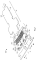
本発明は、自動車部門のための電気コンタクトデバイス1又はコンタクト装置(contact installation)1の2つの実施形態を参照して以下に詳細に説明される。例えば、真っ直ぐに構成、湾曲して構成、又は屈曲させて構成されたコンタクトデバイス1は、導体圧着領域20として構成された少なくとも1つの圧着領域を有する圧着コンタクトデバイス1として構成され、コンタクトデバイス1は、タブ(図1)、ソケット(図2)、ピン又はスタッドコンタクトデバイス、扁平コネクタ(図1)又は挿入スリーブ(図2)として構成することができる。当然のことながら、ここでは言及されていないその他のコンタクトデバイス1上に本発明を使用することは可能である。
The present invention is described in detail below with reference to two embodiments of an
コンタクトデバイス1は、本発明に係る導体圧着領域20を有するだけでよい。電気ケーブルの絶縁体の機械的固定は、圧着せずに、例えば接着剤による接着等によって行うこともできる。コンタクトデバイス1上に設けることができるケーブルは、例えば、電線、ケーブルハーネスのワイヤ又は部品、ケーブル束等である。ケーブルの導体は、撚り線、芯線又は単線でもよいが、容易に圧着することができる撚り線が好ましい。本発明に係るコンタクトデバイス1を備えるケーブルは、組立済み又はプレハブケーブルと呼ばれる。
The
図1及び図2は、夫々、本発明に係るコンタクトデバイス1の打抜きブランク又は整形/打抜きブランクを示し、即ち、コンタクトデバイス1は、開いた状態、即ち、実際の圧着可能なコンタクトデバイス1が実際の圧着可能なコンタクトデバイス1を形成するように垂直に曲げられる即ち整形される前の状態で示されている。打抜きブランク又は整形/打抜きブランクの代わりに、コンタクトデバイス1の任意のその他のブランクを使用することもできる。コンタクトデバイス1は、電気的な相手コンタクトデバイスのための電気的且つ好ましくは機械的なコンタクト領域10を有する。このコンタクト領域10は、移行領域19を介して、ケーブルの圧着可能な導電体のための電気的且つ好ましくは機械的でもある導体圧着領域20に一体化している。
1 and 2 respectively show a punching blank or shaping / punching blank of a
導体圧着領域20は、同様に、移行領域29を介して、好ましくは、ケーブルの(絶縁体による)電気絶縁体及び任意で導電体用の機械的絶縁体圧着領域30に一体化している。この領域は、絶縁体圧着領域30と呼ばれてもよい。ブランク及び/又は整形されたコンタクトデバイス1は、特に打抜きによって行われたその作製の後に、好ましくはリール40又はバンドローラー40(図1)に懸架される。コンタクトデバイス1の圧着作業前、その作業中、又はその作業後、コンタクトデバイス1はリール40から分離することができる。圧着作業後、各圧着領域20,30は、圧着スリーブ20,30とも呼ばれる。
The
コンタクトデバイス1を整形して圧着可能なコンタクトデバイス1を形成する際に、コンタクト領域10の材料層100を曲げて、タブ130、コンタクト舌片130、コンタクトケージ又はコンタクトケーシング等を形成する。この場合、特にタブ130即ちコンタクト舌片130が使用される場合、コンタクトデバイス1上には、別部品として構成された(ロッキング/コンタクト)ケージ即ちケーシングが設けられてもよく、このケージ即ちケーシングよって、実際のコンタクトデバイス1は、例えばハウジング内に係合されることができ、及び/又は、このケージ即ちケーシングは、例えば、コンタクトデバイス1が取り扱われる際、又はコンタクトデバイス1が相手コンタクトデバイスに結合される際、コンタクト舌片130を過伸展から保護するために、コンタクト舌片130を案内、即ち、コンタクト舌片130をその移動の自由度に関して制限する。
When the
更に、打抜きブランクを整形してコンタクトデバイス1を形成する際に、導体圧着領域20の材料層200を真っ直ぐに曲げて、実質的にU字形又はV字形の接続基部210を形成し、且つ少なくとも1つ、好ましくは2つの圧着側面220、タブ220即ち翼220を形成する。電線が導体圧着領域20に圧着される際、圧着側面220は折り曲げられ、導体クリンプが構成される(摩擦/非ポジティブロック係合)。導体圧着領域20の内側は、導体用の固定デバイス230を有する。この固定デバイス230は、好ましくは、鋭利な縁の溝(セレーション)を備えることが好ましく、これらの溝は、圧着中に好ましくはアルミニウムを備える導体の酸化層をこじ開け、部分的な冷間圧接(物質的には係合接続)を確実なものとし、その結果、永久に良好な電気接続を確立する。
Further, when forming the
一体的なコンタクトデバイス1、即ち、容易には分離すことができない又は非ポジティブロック式及び/又はポジティブロック式に結び付けられたコンタクトデバイス1、好ましくは物質的に一体的なコンタクトデバイス1、即ち、物質的に係合する方法で結び付けられて、部品を損傷することなく分離することは不可能であるコンタクトデバイス1、又は特に一体的なコンタクトデバイス1、即ち、単一のピースから成るという意味で均一に製造されたコンタクトデバイス1は、後部に向かってその長手方向Lに、即ち、コンタクト領域10から離れる向きに、絶縁体圧着領域30を有し、絶縁体圧着領域30は、従って、導体圧着領域20に隣接している。絶縁体圧着領域30の単純な断面形状は、圧着作業前は、導体圧着領域20と同様に実質的にU字形又はV字形である。図1及び図2に見ることができる打抜きブランクの形状では、コンタクトデバイス1の実質的に全ての材料層100,200,300は、相互に整列しており、実質的に平面状である。
導体圧着領域20が整形される及び/又は圧着される際、圧着側面220の部分的な変位があり、その結果、コンタクトデバイス1の長手軸Lの方向に接続基部210に対する固定デバイス230の部分的な変位も存在する。これは、絶縁体圧着領域30の方向に固定デバイス230上の矢印(軸を有する)によって図2に示されている。この変位は、圧着側面220の左右の横断方向の端部上に/内に(on/in)おいて最も大きい。その結果、短い「クリンプ」によって、セレーションの機能溝の数即ちその一部が減少する。本発明によれば、従って、固定デバイス230は構成され、且つ、特に、固定デバイス230の長手方向のずれが、好ましくは接続基部210の反対側で補償されることができる又は補償されるように、導体圧着領域20上に/内に(on/in)斜めに配置された状態で設けられる即ち構成される。
When the
図1は、打抜きブランクを整形して実際の圧着可能なコンタクトデバイス1を形成する前の打抜きブランクにおける固定デバイス230の上記のような補償傾斜位置を示す。本発明に係る固定デバイス230は、この目的で、接続基部210上で互いに接触する、即ち、互いに直接隣接する2つの固定ゾーン232,234を有する。単一の固定ゾーン232,234は、好ましくは、少なくとも1つの溝及び/又はリブ、溝付き構造、波形構造、畝状構造又はセレーションを有する3D構造ゾーン、即ち、コンタクトデバイス1の実質的に横断方向Qに延在する幅広な歯を有する「歯状装置」として構成される。この場合、2つの固定ゾーン232,234は、好ましくは、同様に且つ特に長手軸Lに対してミラー反転して構成される。単一の固定ゾーン232,234を固定デバイス230として用いることもできる。
FIG. 1 shows such a compensated tilt position of the fixing
各固定ゾーン232,234は、長手軸Lに対して斜めに角α即ち内角αで設けられる。この場合、角αは、各固定ゾーン232,234の側面とコンタクトデバイス1の長手軸Lの間の角である。角αは、直角よりも小さく、好ましくは、約0.5〜20°小さい。2つの固定ゾーン232,234は、それらの間に鏃状の形状(即ち、軸の無い矢印)を形成し、この矢印の「頭」は、コンタクト領域10から離れてコンタクトデバイス1の打抜きブランクの絶縁体圧着領域30の方を指す。角α、即ち内角αは、この場合、矢印内の長手軸Lからその外境まで延在している(固定ゾーン232に関して図1及び図2を夫々参照)。本発明によれば、打抜きブランクのレイアウトにおいて整形作業(任意ではあるが、圧着)中の固定デバイス230の変位に関する規定が設けられる。
Each of the fixed
圧着可能なコンタクトデバイス1を形成するための打抜きブランクの整形作業中及び/又は圧着可能なコンタクトデバイス1の圧着(整形作業)中には、この角α、即ち内角αは、好ましくは約90°まで増加する。それにより、より小さく且つより薄いコンタクトデバイス1であっても、小さな圧着長さを得ることができ、これは、より短く且つ物質的にも減少したコンタクトデバイス1において見ることができる。かかるコンタクトデバイス1は、特にアルミニウムケーブルに適しているが、銅ケーブル又はその他の導電体を有するケーブルも当然のことながら使用可能である。より効果的な導体圧着又はより効果的な導体圧着スリーブにより、電気的によりロバストな接続が更に生じる。
During the stamping blank shaping operation to form the
コンタクトデバイス1上に/内に(on/in)おいて横断方向Qに連続的である固定デバイス230は、例えばセレーションの打ち抜き(整形打ち抜き方法)により、打抜きブランクの材料層200を弱め、幾つかの部分で固定デバイス230の領域において、比較的大きく減少する。その結果、コンタクトデバイス1は、当該領域において、その反対側よりも不安定になる。この問題は、特に接続基部210の領域における固定デバイス230即ちセレーションの切れ目により、本発明に従って克服され、即ち、コンタクトデバイス1の弱体化は低減する。即ち、本発明によれば、この領域には、固定デバイス230又は固定ゾーン232,234を設けず、好ましくは、コンタクトデバイス1の元の材料層(100),200,(300)が、長手方向Lに維持される。図2を参照のこと。
A fixing
本発明の実施形態では、コンタクトデバイス1の打抜きブランクでは、更に、又は固定デバイス230の斜めの配置に対する代替手段として、好ましくは接続基部210にウェブ213が設けられ、コンタクトデバイス1を補強する。この場合、ウェブ213は、好ましくは、固定ゾーン232,234間、且つ好ましくは移行領域19から移行領域29内の/上の(in/on)位置まで導体圧着領域20上に延在する。ウェブ213は、特にコンタクトデバイス1の未変形の材料層200を備える。それにより、比較的薄いコンタクトデバイス1が、全体的により安定する。
In an embodiment of the present invention, the punching blank of the
コンタクトデバイス1の安定性は、コンタクト領域10に対して接続基部210及び/又は移行領域19上の/内の(on/in)ビード236即ち補強打ち抜き部236によって更に改良されてもよい。ビード236は、この場合、ウェブ213上に、又は任意でその内部に部分的に設けられてもよい。この場合、ビード236は、好ましくは、導体圧着領域20と移行領域19との間に、又は両領域19,20の一方及び/又は両方へ延出するように設けられる。特に接続基部210の領域における本発明に係るウェブ213即ち固定デバイス230の本発明に係る切れ目は、先行技術に係るコンタクトデバイスの従来の固定デバイス上で使用することもできる。
The stability of the
更に、コンタクトデバイス1は、特別な方法によって構成された、ケーブルの絶縁体の機械的圧着のために機能する絶縁体圧着領域30を有してもよい。絶縁体圧着領域30、即ち、圧着基部310及び/又は一方又は両方の圧着側面320は、この場合、ケーブルの絶縁体が、機械的圧着に加えて、絶縁体圧着領域30によって機械的に固定されることができるように絶縁体を固定するための絶縁体固定デバイス330を有する。絶縁体固定デバイス330は、少なくとも1つのメゾスコピック又はマクロスコピックな凹み及び/又は少なくとも1つのメゾスコピック又はマクロスコピックな突起を備える。絶縁体圧着領域30とケーブルの絶縁体との間で絶縁体圧着が構成される際、突起は、好ましくは、絶縁体及び/又は凹み内の絶縁体内で係合する。
Furthermore, the
絶縁体圧着領域30の材料層300は、絶縁体固定デバイス330として、好ましくは異なる材料厚みを有する少なくとも1つの絶縁体固定ゾーン332,334を有する。絶縁体固定デバイス330の材料層300は、この場合、第1の点について、材料層300の単純な断面形状を有し、第2の点について、この断面形状からの逸脱を有する。絶縁体圧着領域30は、コンタクトデバイス1の横断方向Q及び/又は長手方向Lに,複数の相互に離間した絶縁体固定ゾーン332,332,332,334,334,334を有してもよい。
The
本発明の実施形態では、絶縁体圧着領域30は、好ましくは、複数の、特に2つ、3つ又は4つの同様な絶縁体固定ゾーン332,334が横断方向Qに互いに離間し、また、好ましくは、複数の、特に2つの異なる絶縁体固定ゾーン332,334が長手方向Lに互いに離間している。第1の絶縁体固定ゾーン332は、好ましくは、好ましくは少なくとも1つのリブ又は溝を備える第1の種類の3D構造ゾーン332である。第2の絶縁体固定ゾーン334は、好ましくは、好ましくは少なくとも1つのカム又は爪を備える第2の種類の3D構造ゾーン334である。
In an embodiment of the present invention, the
本発明の好適な実施形態では、コンタクトデバイス1の絶縁体圧着領域30は、横断方向Qに、複数の、特に4つの第1の種類の3D構造ゾーン332と、複数の、特に3つの第2の種類の3D構造ゾーン334を有する。この場合、第1の種類の3D構造ゾーン332は、好ましくは、横断方向Qに第2の種類の3D構造ゾーン334と交互になっていてよく、第1の種類の3D構造ゾーン332は、好ましくは、長手方向Lに第2の種類の3D構造ゾーン334に対して、特に重なり合わずに互いに隣接してよい。
In a preferred embodiment of the present invention, the
絶縁体固定デバイス300の2つの絶縁体固定ゾーン332,332,332,334,334,334は、本発明によれば、好ましくは、はっきりと互いに分離された状態、即ち、互いに区切られた又は互いから締め出された状態に設けられる。即ち、2つの絶縁体固定ゾーン332,332,332,334,334,334は、好ましくは、互いに一体化しない。しかし、これは、境界領域では可能である。特に、少なくとも2つの絶縁体固定ゾーン332,332,332,334,334,334は、互いに隣接して、特に互いに直接隣接して設けられる。好ましくは、絶縁体固定ゾーン332,332,332,334,334,334は、絶縁体圧着領域30の横断方向Qに設けられ、任意で圧着側面320の横断方向端又は横断方向端部分を除いて、絶縁体固定ゾーン332,332,332,334,334,334が絶縁体圧着領域30の横断方向Qの実質的に全体を架橋するように、任意で直線状に又はジグザグに交互になっている。
According to the invention, the two
原理上は、絶縁体圧着領域30上の/内の(on/in)絶縁体固定ゾーン332,332,332,334,334,334の可能な分布は、任意の種類のものでもよい。しかしながら、これらは、好ましくは、コンタクトデバイス1が曲げられる際及び/又はケーブルが絶縁体圧着領域30上で屈曲される際に、ケーブルの絶縁体が絶縁体クリンプから滑り落ちないように、即ち、コンタクトデバイス1の絶縁体圧着領域30から滑り落ちないように分布するように選択及び/又は配置をされる。この場合、2つの絶縁体固定ゾーン332,334の1つの組み合わせ又は複数の組み合わせが好ましく、第1の種類の絶縁体固定ゾーン332は、弾性的にのみケーブルの絶縁体を変形し、第2の種類の絶縁体固定ゾーン334は、弾性的に、且つ任意で塑性的に、例えば、食い込み又は突き刺しによってケーブルの絶縁体を変形させる。
In principle, the possible distributions of the
絶縁体固定ゾーン332,332,332,334,334,334は、好ましくは、絶縁体圧着領域30とケーブルの絶縁体との間に液密接続を生じさせることができるように構成される。これは、例えば、2つの異なる絶縁体固定ゾーン332,334(図1及び2を参照)が、互い違いに交互に配置されるように行われてもよい。この場合、第1の種類の絶縁体固定ゾーン332は、横断方向Qに長手方向位置に互いに離間して設けられてもよい。同様に、第2の種類の絶縁体固定ゾーン334の列も互い違いに配置され、即ち、これらも、別の長手方向位置に横断方向Qに互いに離間して設けられる。第1の種類の2つの直接隣接する絶縁体固定ゾーン332の間の横断方向Qの間隙は、この場合、第2の種類の絶縁体固定ゾーン334と実質的に同じくらい又はそれよりも僅かに大きい又は小さく、またその逆も然りである。
更に、導体圧着領域20と絶縁体圧着領域30との間の移行領域29に横断方向Qに切り込みを入れない、即ち、はっきりと互いに対してずれた又は互いから分離した圧着側面220,320を設けないことが好ましい。即ち、このような場合、コンタクトデバイス1上に/内に圧着翼220,320がない。これは、図1及び図2に明確に見ることができ、コンタクトデバイス1は、好ましくは、導体圧着領域20から絶縁体圧着領域30の方向に横断方向Qに広くなっていくか(図1及び図2を参照)、横断方向Qのその寸法を実質的に又は主に維持する。
Furthermore, there are provided crimping
コンタクトデバイス1の単一の組み立てられた圧着側面220,29,320、即ち、コンタクトデバイス1の長手方向側の組み立てられた圧着側面220,29,320は、この場合、導体圧着領域20の単一の圧着側面220(圧着翼220)と、絶縁体圧着領域30と移行領域29との間に位置する絶縁体圧着領域30と移行領域29の単一の圧着側面320(圧着翼320)を備える。組み立てられた圧着側面220,29,320の外縁は、この場合、コンタクトデバイス1の長手軸Lから離間して設けられる。即ち、移行領域29は、仮想の圧着翼220,320(圧着側面220,320)間の間隙を実質的に完全に埋める。
The single assembled crimping
Claims (12)
ケーブルの導体の電気接続用の導体圧着領域(20)を有し、前記導体圧着領域(20)は、前記導体を固定するための固定デバイス(230,232,234)を有し、
少なくとも前記コンタクトデバイス(1)のブランクにおいて、前記固定デバイス(230,232,234)は、前記コンタクトデバイス(1)の長手軸(L)に対して斜めに延在し、及び/又は、前記固定デバイス(230,232,234)は、前記コンタクトデバイス(1)の横断方向(Q)に前記導体圧着領域(20)のウェブ(233)によって遮断されることを特徴とする電気圧着コンタクトデバイス(1)。 An electro-crimp contact device (1), preferably for the automotive sector, preferably a tab contact device (1), a splice contact device or a socket contact device (1), in particular for aluminum cables,
A conductor crimping region (20) for electrical connection of a conductor of the cable, the conductor crimping region (20) having a fixing device (230, 232, 234) for fixing the conductor;
At least in the blank of the contact device (1), the fixing device (230, 232, 234) extends obliquely with respect to the longitudinal axis (L) of the contact device (1) and / or is fixed An electro-crimp contact device (1) characterized in that the device (230, 232, 234) is interrupted by a web (233) in the conductor crimp region (20) in the transverse direction (Q) of the contact device (1). ).
前記導体圧着領域(20)の接続基部(210)に対して曲げ又は圧着中に前記長手軸(L)の方向に前記導体圧着領域(20)の圧着側面(220)のずれが補償されることができることように、及び/又は、補償されるように構成されることを特徴とする、
請求項1に記載の電気コンタクトデバイス。 The oblique arrangement of the orbits of the fixing devices (230, 232, 234)
The displacement of the crimping side surface (220) of the conductor crimping region (20) in the direction of the longitudinal axis (L) during bending or crimping to the connection base (210) of the conductor crimping region (20) is compensated. And / or is configured to be compensated for,
The electrical contact device according to claim 1.
請求項1又は2に記載の電気コンタクトデバイス。 The conductor crimping region is such that the V-shaped structure of the fixing device (230, 232, 234) is such that the tip of the V-shaped structure points in the direction of the insulator crimping region (30) of the contact device (10). (20) manufactured,
The electrical contact device according to claim 1 or 2.
請求項1〜3のいずれか一項に記載の電気コンタクトデバイス。 The side face angle (α) of the V-shaped structure or the fixing device (230, 232, 234) with respect to the longitudinal axis (L) is greater than zero and less than a right angle, and the angle (α) is preferably Is 45 ° to 89 °, particularly 70 ° to 73 °, 75 ° to 78 °, 80 ° to 83 °, 85 ° to 87 ° ± 1 ° to 2 °,
The electrical contact device as described in any one of Claims 1-3.
請求項1〜4のいずれか一項に記載の電気コンタクトデバイス。 The fixation device (230, 232, 234) includes a first fixation zone (232) and a second fixation zone (234), and one or both of the fixation devices (230, 232, 234) ( 232, 234) extends obliquely with respect to the longitudinal axis (L),
The electrical contact device as described in any one of Claims 1-4.
請求項1〜5のいずれか一項に記載の電気コンタクトデバイス。 The first fixing zone (232) of the fixing device (230, 232, 234) is connected to the second fixing zone (234) of the fixing device (230, 232, 234) with respect to the conductor crimping region ( 20) Manufactured on / in mirror inversion, characterized in that the mirror axis (L) is preferably the longitudinal axis (L) of the contact device (1),
The electrical contact device as described in any one of Claims 1-5.
請求項1〜6のいずれか一項に記載の電気コンタクトデバイス。 The web (233) of the conductor crimping region (20) is provided in the transverse direction (Q) between the first fixing zone (232) and the second fixing zone (234), The web (233) is preferably constituted by the complete thickness of the material layer (200) of the conductor crimping region (20),
The electrical contact device as described in any one of Claims 1-6.
前記固定デバイス(230,232,234)又は前記固定ゾーン(232,234)は、好ましくは、少なくとも1つのリブ及び/又は溝、又は溝構造、波形構造、畝状構造又はセレーションを有することを特徴とする、
請求項1〜7のいずれか一項に記載の電気コンタクトデバイス。 The fixation device (230, 232, 234) or the fixation zone (232, 234) is a 3D structure zone (230, 232, 234),
Said fixation device (230, 232, 234) or said fixation zone (232, 234) preferably has at least one rib and / or groove, or groove structure, corrugated structure, saddle structure or serration. And
The electrical contact device as described in any one of Claims 1-7.
請求項1〜8のいずれか一項に記載の電気コンタクトデバイス。 The insulator crimping region (30) functions to mechanically clamp the insulator of the cable, and the insulator crimping region (30) is configured so that the insulator of the cable is connected to the insulator crimping region (30). In addition to the mechanical clamping according to claim 1), characterized in that it has an insulator fixing device (330, 332, 334) of the kind that can be mechanically fixed,
The electrical contact device as described in any one of Claims 1-8.
第1の絶縁体固定ゾーン(332)は、好ましくは、少なくとも1つのリブ又は溝、又は溝構造、波形構造、畝状構造又はセレーションを有し、及び/又は、第2の絶縁体固定ゾーン(334)は、好ましくは、少なくとも1つのカム、爪又はフック、又は瘤状構造、針構造又はフック構造を有することを特徴とする、
請求項1〜9のいずれか一項に記載の電気コンタクトデバイス。 The insulator fixing device (330, 332, 334) comprises at least two, preferably insulator fixing zones (332, 334) for mechanical fixation configured differently,
The first insulator fixing zone (332) preferably has at least one rib or groove, or groove structure, corrugated structure, saddle structure or serration and / or the second insulator fixing zone ( 334) is preferably characterized by having at least one cam, claw or hook, or knob-like structure, needle structure or hook structure,
The electrical contact device as described in any one of Claims 1-9.
請求項1〜10のいずれか一項に記載の電気コンタクトデバイス。 The at least two insulator fixing zones (332, 334) are clearly separated from each other as an insulator fixing device (330, 332, 334) on / in the insulator crimping region (30). The first insulator fixing zone (332) is preferably provided directly adjacent to the second insulator fixing zone (333),
The electrical contact device as described in any one of Claims 1-10.
前記組立済みケーブルは、請求項1〜11のいずれか一項に記載の電気圧着コンタクトデバイス(1)を有することを特徴とする組立済み電気ケーブル。 Assembled electrical cable, especially for the automotive sector, especially for aluminum cables,
12. An assembled electrical cable, characterized in that the assembled cable has an electro-crimp contact device (1) according to any one of claims 1-11.
Applications Claiming Priority (3)
| Application Number | Priority Date | Filing Date | Title |
|---|---|---|---|
| DE102013203796.1 | 2013-03-06 | ||
| DE102013203796.1A DE102013203796A1 (en) | 2013-03-06 | 2013-03-06 | Electric crimp contact device |
| PCT/EP2014/054299 WO2014135610A1 (en) | 2013-03-06 | 2014-03-06 | Electrical crimp contact device |
Publications (2)
| Publication Number | Publication Date |
|---|---|
| JP2016509357A true JP2016509357A (en) | 2016-03-24 |
| JP6543196B2 JP6543196B2 (en) | 2019-07-10 |
Family
ID=50236176
Family Applications (1)
| Application Number | Title | Priority Date | Filing Date |
|---|---|---|---|
| JP2015560681A Active JP6543196B2 (en) | 2013-03-06 | 2014-03-06 | Electro crimp contact device |
Country Status (6)
| Country | Link |
|---|---|
| US (1) | US9768524B2 (en) |
| EP (1) | EP2965383B1 (en) |
| JP (1) | JP6543196B2 (en) |
| CN (1) | CN105164857B (en) |
| DE (1) | DE102013203796A1 (en) |
| WO (1) | WO2014135610A1 (en) |
Cited By (4)
| Publication number | Priority date | Publication date | Assignee | Title |
|---|---|---|---|---|
| JP2017143028A (en) * | 2016-02-12 | 2017-08-17 | 古河電気工業株式会社 | Female terminal and wiring harness with the same |
| JP2020102305A (en) * | 2018-12-20 | 2020-07-02 | 矢崎総業株式会社 | connector |
| JP7364394B2 (en) | 2019-09-04 | 2023-10-18 | 矢崎総業株式会社 | Crimp terminals and wires with terminals |
| JP7404176B2 (en) | 2020-07-15 | 2023-12-25 | 矢崎総業株式会社 | wire with terminal |
Families Citing this family (15)
| Publication number | Priority date | Publication date | Assignee | Title |
|---|---|---|---|---|
| JP2016164836A (en) * | 2015-03-06 | 2016-09-08 | 株式会社オートネットワーク技術研究所 | Electric wire with terminal and terminal |
| DE102015224219A1 (en) * | 2015-12-03 | 2017-06-08 | Te Connectivity Germany Gmbh | Crimp contact with improved contact and crimp connection |
| DE202016102186U1 (en) | 2016-04-25 | 2016-05-09 | Erni Production Gmbh & Co. Kg | contact sleeve |
| DE102016107659A1 (en) | 2016-04-25 | 2017-10-26 | Erni Production Gmbh & Co. Kg | contact sleeve |
| JP2018037374A (en) * | 2016-09-02 | 2018-03-08 | 矢崎総業株式会社 | Electric wire with terminal |
| JP6858552B2 (en) * | 2016-12-27 | 2021-04-14 | 矢崎総業株式会社 | Crimping terminal |
| JP6904147B2 (en) * | 2017-08-01 | 2021-07-14 | 株式会社オートネットワーク技術研究所 | Wire with terminal |
| JP6709806B2 (en) * | 2018-01-18 | 2020-06-17 | 矢崎総業株式会社 | Crimper |
| JP7096966B2 (en) * | 2018-02-13 | 2022-07-07 | スミダコーポレーション株式会社 | Manufacturing method of the tip structure of the flat wire |
| DE102019109460A1 (en) * | 2019-04-10 | 2020-10-15 | Te Connectivity Germany Gmbh | Crimp contact |
| JP7264014B2 (en) * | 2019-11-11 | 2023-04-25 | 住友電装株式会社 | Wires with terminals and connectors |
| JP7116112B2 (en) * | 2020-03-18 | 2022-08-09 | 矢崎総業株式会社 | Wire with terminal |
| JP2021150235A (en) * | 2020-03-23 | 2021-09-27 | 矢崎総業株式会社 | Terminal-having electric wire and manufacturing method for terminal-having electric wire |
| US11264735B1 (en) * | 2020-08-28 | 2022-03-01 | TE Connectivity Services Gmbh | Electrical terminal for terminating a wide size range of magnet wires |
| EP3989363A1 (en) | 2020-10-26 | 2022-04-27 | Aptiv Technologies Limited | Electrical crimp terminal |
Citations (5)
| Publication number | Priority date | Publication date | Assignee | Title |
|---|---|---|---|---|
| JPS55120080U (en) * | 1979-02-16 | 1980-08-25 | ||
| JP2002367688A (en) * | 2001-06-08 | 2002-12-20 | Sumitomo Wiring Syst Ltd | Terminal fitting |
| JP2009245697A (en) * | 2008-03-31 | 2009-10-22 | Furukawa Electric Co Ltd:The | Crimp terminal |
| JP2010198776A (en) * | 2009-02-23 | 2010-09-09 | Furukawa Electric Co Ltd:The | Crimp terminal for aluminum wire, and crimping structure to aluminum wire using the same |
| JP2012155889A (en) * | 2011-01-24 | 2012-08-16 | Auto Network Gijutsu Kenkyusho:Kk | Wire with terminal and crimp terminal |
Family Cites Families (19)
| Publication number | Priority date | Publication date | Assignee | Title |
|---|---|---|---|---|
| US2854648A (en) * | 1957-03-11 | 1958-09-30 | Berg Quentin | Electrical connector |
| US4142771A (en) * | 1974-10-16 | 1979-03-06 | Amp Incorporated | Crimp-type terminal |
| US3989339A (en) * | 1975-10-02 | 1976-11-02 | Thomas & Betts Corporation | Electrical connector and method of making same |
| DE3634099C2 (en) * | 1986-10-07 | 1994-12-01 | Vossloh Schwabe Gmbh | Electrical connection or connection terminal |
| JPH0736364U (en) * | 1993-12-10 | 1995-07-04 | 住友電装株式会社 | Terminal for high voltage resistance wire |
| US5658163A (en) * | 1995-12-19 | 1997-08-19 | Molex Incorporated | Terminal for connecting electrical wires |
| JP2003243057A (en) * | 2002-02-18 | 2003-08-29 | Auto Network Gijutsu Kenkyusho:Kk | Terminal for connection of electric wire |
| JP5024948B2 (en) * | 2007-11-16 | 2012-09-12 | 矢崎総業株式会社 | Crimp structure of aluminum wire and terminal |
| JP5119532B2 (en) * | 2008-01-28 | 2013-01-16 | 矢崎総業株式会社 | Crimp terminal for aluminum wire |
| DE112009000314T5 (en) * | 2008-02-15 | 2010-12-16 | AUTONETWORKS Technologies, LTD., Yokkaichi | Connector and harness |
| JP5076072B2 (en) * | 2008-03-24 | 2012-11-21 | 矢崎総業株式会社 | Crimp terminal and crimp structure using this crimp terminal |
| JP2009272141A (en) * | 2008-05-07 | 2009-11-19 | Autonetworks Technologies Ltd | Crimping terminal, and method for manufacturing of electric cable with terminal |
| JP2010010000A (en) * | 2008-06-27 | 2010-01-14 | Autonetworks Technologies Ltd | Terminal metal fixture and wire with terminal |
| JP2010021016A (en) * | 2008-07-10 | 2010-01-28 | Sumitomo Wiring Syst Ltd | Terminal metal fitting and electric cable with terminal |
| CN101814662B (en) * | 2009-02-20 | 2012-12-19 | 华为技术有限公司 | Clamping connector and communications device |
| JP5297253B2 (en) * | 2009-04-07 | 2013-09-25 | 矢崎総業株式会社 | Crimp terminal |
| JP2011216253A (en) * | 2010-03-31 | 2011-10-27 | Yazaki Corp | Crimp terminal and wire connection structure of crimp terminal |
| JP5765975B2 (en) * | 2011-03-07 | 2015-08-19 | 矢崎総業株式会社 | Crimp terminal |
| DE202013001074U1 (en) * | 2013-02-01 | 2013-02-20 | Tyco Electronics Amp Gmbh | Electrical contact device, in particular crimp contact device |
-
2013
- 2013-03-06 DE DE102013203796.1A patent/DE102013203796A1/en not_active Ceased
-
2014
- 2014-03-06 CN CN201480024426.9A patent/CN105164857B/en active Active
- 2014-03-06 JP JP2015560681A patent/JP6543196B2/en active Active
- 2014-03-06 EP EP14708254.9A patent/EP2965383B1/en active Active
- 2014-03-06 WO PCT/EP2014/054299 patent/WO2014135610A1/en active Application Filing
-
2015
- 2015-09-04 US US14/846,026 patent/US9768524B2/en active Active
Patent Citations (5)
| Publication number | Priority date | Publication date | Assignee | Title |
|---|---|---|---|---|
| JPS55120080U (en) * | 1979-02-16 | 1980-08-25 | ||
| JP2002367688A (en) * | 2001-06-08 | 2002-12-20 | Sumitomo Wiring Syst Ltd | Terminal fitting |
| JP2009245697A (en) * | 2008-03-31 | 2009-10-22 | Furukawa Electric Co Ltd:The | Crimp terminal |
| JP2010198776A (en) * | 2009-02-23 | 2010-09-09 | Furukawa Electric Co Ltd:The | Crimp terminal for aluminum wire, and crimping structure to aluminum wire using the same |
| JP2012155889A (en) * | 2011-01-24 | 2012-08-16 | Auto Network Gijutsu Kenkyusho:Kk | Wire with terminal and crimp terminal |
Cited By (5)
| Publication number | Priority date | Publication date | Assignee | Title |
|---|---|---|---|---|
| JP2017143028A (en) * | 2016-02-12 | 2017-08-17 | 古河電気工業株式会社 | Female terminal and wiring harness with the same |
| JP2020102305A (en) * | 2018-12-20 | 2020-07-02 | 矢崎総業株式会社 | connector |
| JP7010810B2 (en) | 2018-12-20 | 2022-01-26 | 矢崎総業株式会社 | connector |
| JP7364394B2 (en) | 2019-09-04 | 2023-10-18 | 矢崎総業株式会社 | Crimp terminals and wires with terminals |
| JP7404176B2 (en) | 2020-07-15 | 2023-12-25 | 矢崎総業株式会社 | wire with terminal |
Also Published As
| Publication number | Publication date |
|---|---|
| CN105164857B (en) | 2018-09-21 |
| CN105164857A (en) | 2015-12-16 |
| DE102013203796A1 (en) | 2014-09-11 |
| US9768524B2 (en) | 2017-09-19 |
| WO2014135610A1 (en) | 2014-09-12 |
| EP2965383A1 (en) | 2016-01-13 |
| EP2965383B1 (en) | 2019-12-04 |
| US20150380834A1 (en) | 2015-12-31 |
| JP6543196B2 (en) | 2019-07-10 |
Similar Documents
| Publication | Publication Date | Title |
|---|---|---|
| JP6543196B2 (en) | Electro crimp contact device | |
| AU2013206689B2 (en) | Electrical crimp contact device | |
| US9054431B2 (en) | Press bond terminal | |
| US20080280510A1 (en) | Electrical contact | |
| WO2010024033A1 (en) | Terminal metal fitting and method of manufacturing terminal metal fitting | |
| US8992271B2 (en) | Electrical terminal | |
| JP2009231080A (en) | Crimp terminal for aluminum wire | |
| US9496636B2 (en) | Female terminal having opposed first and second pluralities of resilient pieces, with each resilient piece having a free end and a contact portion near the free end | |
| JP2007059304A (en) | Wire with terminal and its manufacturing method | |
| EP1168501B1 (en) | A terminal fitting | |
| CA2636019A1 (en) | Contact with improved retention member | |
| JP2010073442A (en) | Terminal fitting and electric wire with terminal fitting | |
| US20230055994A1 (en) | Crimp Terminal | |
| JP2003016850A (en) | Flat circuit body, and method of manufacturing the same | |
| JP4057301B2 (en) | Flat cable connection terminal and connection method between flat cable and connection terminal | |
| JP3875037B2 (en) | Pressure contact terminal | |
| JP3860728B2 (en) | Piercing terminal | |
| JP2015099639A (en) | Terminal metal fitting | |
| EP1168504B1 (en) | An insulation-displacement terminal fitting | |
| JP2020194718A (en) | Metal terminal and electric wire with terminal | |
| JP2004071180A (en) | Flat cable connection jig and connection method of flat cable connection metal fitting to flat cable | |
| JPH1092481A (en) | Pressure contacting terminal | |
| JPH10162878A (en) | Crimp terminal metal | |
| JP2002343474A (en) | Flat cable connector and flat cable connecting part | |
| JP2002313447A (en) | Insulation displacement contact terminal |
Legal Events
| Date | Code | Title | Description |
|---|---|---|---|
| A621 | Written request for application examination |
Free format text: JAPANESE INTERMEDIATE CODE: A621 Effective date: 20170220 |
|
| A977 | Report on retrieval |
Free format text: JAPANESE INTERMEDIATE CODE: A971007 Effective date: 20180125 |
|
| A131 | Notification of reasons for refusal |
Free format text: JAPANESE INTERMEDIATE CODE: A131 Effective date: 20180206 |
|
| A521 | Request for written amendment filed |
Free format text: JAPANESE INTERMEDIATE CODE: A523 Effective date: 20180502 |
|
| A131 | Notification of reasons for refusal |
Free format text: JAPANESE INTERMEDIATE CODE: A131 Effective date: 20181016 |
|
| A521 | Request for written amendment filed |
Free format text: JAPANESE INTERMEDIATE CODE: A523 Effective date: 20190111 |
|
| TRDD | Decision of grant or rejection written | ||
| A01 | Written decision to grant a patent or to grant a registration (utility model) |
Free format text: JAPANESE INTERMEDIATE CODE: A01 Effective date: 20190528 |
|
| A61 | First payment of annual fees (during grant procedure) |
Free format text: JAPANESE INTERMEDIATE CODE: A61 Effective date: 20190614 |
|
| R150 | Certificate of patent or registration of utility model |
Ref document number: 6543196 Country of ref document: JP Free format text: JAPANESE INTERMEDIATE CODE: R150 |
|
| R250 | Receipt of annual fees |
Free format text: JAPANESE INTERMEDIATE CODE: R250 |
|
| R250 | Receipt of annual fees |
Free format text: JAPANESE INTERMEDIATE CODE: R250 |