JP7010042B2 - Braking force control device - Google Patents
Braking force control device Download PDFInfo
- Publication number
- JP7010042B2 JP7010042B2 JP2018022383A JP2018022383A JP7010042B2 JP 7010042 B2 JP7010042 B2 JP 7010042B2 JP 2018022383 A JP2018022383 A JP 2018022383A JP 2018022383 A JP2018022383 A JP 2018022383A JP 7010042 B2 JP7010042 B2 JP 7010042B2
- Authority
- JP
- Japan
- Prior art keywords
- vehicle
- speed
- braking force
- braking
- slope
- Prior art date
- Legal status (The legal status is an assumption and is not a legal conclusion. Google has not performed a legal analysis and makes no representation as to the accuracy of the status listed.)
- Active
Links
Images


Description
本明細書では、車両の制動力制御装置を開示する。 This specification discloses a braking force control device for a vehicle.
特許文献1には、車両の制御方法が開示されている。車両は、ブレーキシステムとブレーキコントローラとを備える。ブレーキシステムは、ブレーキペダルと、アクチュエータと、ホイルシリンダと、を備える。運転者によってブレーキペダルが踏まれ、車両が坂道に停車していると判別されると、ブレーキコントローラは、アクチュエータを制御し、ホイルシリンダの油圧を維持する。ブレーキコントローラは、運転者によって、ブレーキペダルが踏まれている状態からブレーキペダルが開放されても、ホイルシリンダの油圧を低下させない。これにより、車両に制動力が加わって、車両が坂道を降下しない。 Patent Document 1 discloses a vehicle control method. The vehicle is equipped with a brake system and a brake controller. The brake system includes a brake pedal, an actuator, and a foil cylinder. When the driver depresses the brake pedal and determines that the vehicle is parked on a slope, the brake controller controls the actuator to maintain hydraulic pressure in the foil cylinder. The brake controller does not reduce the hydraulic pressure of the foil cylinder even when the brake pedal is released from the state where the brake pedal is depressed by the driver. As a result, braking force is applied to the vehicle so that the vehicle does not descend the slope.
上記の技術では、坂道に停車していた車両が発進するタイミングではブレーキコントローラによるアクチュエータの制御が解除され、ホイルシリンダの油圧が急激に低下する。この構成では、例えば、車両の発進後に、運転者がアクセルを離して車両が前進する推進力が無くなると、車両に制動力が加わらず、車両が坂道から降下する可能性がある。 In the above technology, the control of the actuator by the brake controller is released at the timing when the vehicle stopped on the slope starts, and the hydraulic pressure of the foil cylinder drops sharply. In this configuration, for example, if the driver releases the accelerator and the vehicle loses the propulsive force to move forward after the vehicle starts, the braking force is not applied to the vehicle and the vehicle may descend from the slope.
本明細書では、車両が坂道に停車されている状態から、発進される際に、車両が坂道から降下する事態を抑制することができる技術を提供する。 The present specification provides a technique capable of suppressing a situation in which a vehicle descends from a slope when the vehicle is started from a state where the vehicle is stopped on the slope.
本明細書によって開示される制動力制御装置は、運転者に操作されるブレーキ操作部を備えるブレーキ装置であって、車両を制動するための制動力を加える前記ブレーキ装置を制御する制動力制御装置であって、前記車両の速度を取得する取得部と、前記車両が坂道に位置することを特定する特定部と、前記車両が前記坂道に位置することが特定され、前記車両が停車されていることを示す前記速度が取得され、前記運転者によって前記ブレーキ操作部に前記車両を制動するための制動操作が実行されていない場合に、前記車両が前記坂道を降下することを抑制するための前記制動力を加える抑制動作を前記ブレーキ装置に実行させる制御部であって、前記抑制動作が実行されている間に、上昇する前記速度が取得される場合に、前記速度の上昇に従って、前記制動力を徐々に低下させる前記制御部と、を備えてもよい。 The braking force control device disclosed in the present specification is a braking device including a brake operating unit operated by a driver, and is a braking force control device that controls the braking device that applies a braking force for braking a vehicle. The acquisition unit for acquiring the speed of the vehicle, the specific unit for specifying that the vehicle is located on the slope, and the specific unit for specifying that the vehicle is located on the slope are specified, and the vehicle is stopped. The above-mentioned for suppressing the vehicle from descending the slope when the speed indicating that the speed is acquired and the braking operation for braking the vehicle is not executed by the driver on the brake operation unit. A control unit that causes the braking device to execute a restraining operation for applying a braking force. When the speed to be increased is acquired while the suppressing operation is being executed, the braking force is increased according to the increase in the speed. May be provided with the control unit, which gradually lowers the speed.
上記の構成では、上昇する速度が取得される場合、速度の上昇に従って、制動力が徐々に低下される。この構成によれば、車両が坂道に停車されている状態から発進される際に、例えば、発進後に運転者がアクセルを離す等、車両の推進力が無くなるような状況においても、車両が坂道から降下する事態を抑制することができる。 In the above configuration, when an ascending speed is acquired, the braking force is gradually decreased as the speed increases. According to this configuration, when the vehicle is started from a state where it is stopped on a slope, the vehicle is off the slope even in a situation where the propulsive force of the vehicle is lost, for example, when the driver releases the accelerator after the start. It is possible to suppress the situation of descent.
図1から図5を参照して、本実施例の制動力制御装置50について説明する。制動力制御装置50は、例えば自動車等の車両10に搭載される。制動力制御装置50は、後述するブレーキ装置30を制御する。これによって、車両10に制動力が加えられる。
The braking
図1、図2、及び図3に示されるように、車両10は、駆動装置12と、ブレーキ装置30と、制動力制御装置50と、速度センサ22と、加速度センサ24と、シフトポジションセンサ26と、車輪20と、を備える。
As shown in FIGS. 1, 2, and 3, the
駆動装置12と車輪20とは、車両10に搭載されている。図1に示されるように、駆動装置12は、エンジン14と、変速機16と、アクセル操作部18と、を備える。エンジン14は、燃料を燃焼させて、トルクを発生させる。エンジン14には、変速機16が連結されている。変速機16は、エンジン14で発生するトルクを車輪20に伝達する。アクセル操作部18は、運転者によって操作されるアクセルペダルを備える。運転者は、アクセル操作部18の操作量を変動させることによって、エンジン14の回転数を変動させる。これにより、エンジン14から発生するトルクが変動する。
The
ブレーキ装置30は、車両10に搭載されている。ブレーキ装置30は、車両10を制動するための制動力を発生する。図3に示されるように、ブレーキ装置30は、ブレーキ操作部32と、ブースタ34と、マスタシリンダ36と、連結管38,41と、アクチュエータ40と、ホイルシリンダ42,44,46,48と、を備える。ブレーキ操作部32は、運転者によって操作されるブレーキペダルを備える。運転者がブレーキ操作部32の操作を実行すると(例えばブレーキペダルを踏むと)、その操作力がブースタ34によって増幅され、マスタシリンダ36に出力される。これにより、マスタシリンダ36に油圧が発生する。マスタシリンダ36には、連結管38を介して、アクチュエータ40が連結されている。アクチュエータ40は、アクチュエータ40とマスタシリンダ36とを連通させたり、閉塞させたりする。アクチュエータ40には、連結管41を介して、ホイルシリンダ42,44,46,48が連結されている。ホイルシリンダ42,44,46,48は、アクチュエータ40と連通している。ホイルシリンダ42,44,46,48には、アクチュエータ40と連結管38,41とを介して、マスタシリンダ36から油圧が供給される。ホイルシリンダ42,44,46,48のそれぞれは、車輪20に連結されている。ホイルシリンダ42,44,46,48は、マスタシリンダ36から供給される油圧によって、車輪20、即ち車両10に制動力を加える。このときの運転者のブレーキ操作部32への操作(例えばブレーキペダルを踏む操作)を、制動操作と呼ぶ。
The
速度センサ22は、車両10に搭載されている。速度センサ22は、回転数検出部と変換回路とを備える。速度センサ22は、回転数検出部において、車輪20の回転数を検出する。速度センサ22は、変換回路において、車輪20の回転数から車両10の速度を算出する。
The
加速度センサ24は、車両10に搭載されている。加速度センサ24は、車両10に対する水平方向と垂直方向とにおける車両10の加速度のそれぞれを検出する。
The
シフトポジションセンサ26は、車両10に搭載されている。シフトポジションセンサ26は、図示省略したシフトレバーによって指定されているシフトポジションを検出する。シフトポジションは、例えば、ドライブ、リバース、ニュートラル、パーキング等を含む。シフトポジションは、エンジン14のトルクが車輪20に伝達される第1種のシフトポジション(例えばドライブ、リバース等)と、エンジン14のトルクが車輪20に伝達されない第2種のシフトポジション(例えばパーキング、ニュートラル等)と、に分類される。なお、電気自動車である場合、エンジン14に替えて、あるいはエンジン14と共に、モータのトルクが車輪20に伝達されるか否かでシフトポジションが分類されてもよい。
The
制動力制御装置50は、車両10に搭載されている。図2に示されるように、制動力制御装置50は、制御部52と、取得部54と、特定部56と、シフトポジション判別部58と、を備える。制御部52は、取得部54と、特定部56と、シフトポジション判別部58と、ブレーキ装置30と、に電気的に接続されている。制御部52は、ブレーキ装置30を制御する。取得部54は、速度センサ22に電気的に接続されている。取得部54は、速度センサ22から、車両10の速度を取得する。特定部56は、加速度センサ24に電気的に接続されている。特定部56は、加速度センサ24から、検出結果を取得する。特定部56は、取得済みの検出結果から、車両10が坂道に停車しているか否かを特定する。シフトポジション判別部58は、シフトポジションセンサ26に電気的に接続されている。シフトポジション判別部58は、シフトポジションセンサ26から、シフトポジションを取得する。シフトポジション判別部58は、取得済みのシフトポジションが、第2種のシフトポジションであるか否かを判別する。
The braking
次に、図4を参照して、制動力制御装置50の動作を説明する。エンジン14が駆動している間、取得部54は、速度センサ22から車両10の速度を取得する。また、特定部56は、加速度センサ24から検出結果を取得し、車両10が坂道に位置するか否かを特定する。さらに、シフトポジション判別部58は、シフトポジションセンサ26からシフトポジションを取得し、第2種のシフトポジションであるか否かを判断する。
Next, the operation of the braking
続いて、車両10が坂道に停車している状態から発進する状況における制動力制御装置50の処理を説明する。車両10が坂道に停車している状態から発進する状況では、運転者は、ブレーキ操作部32に制動操作を実行し、シフトポジションを第2種のシフトポジションから第1種のシフトポジションに切り替える。続いて、運転者は、ブレーキ操作部32の制動操作を停止して、アクセル操作部18の操作に移行する。
Subsequently, the processing of the braking
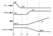
運転者による制動操作が停止されるまでは、取得部54は、速度センサ22から車両10の速度(即ちゼロ)を取得する。これにより、制御部52は、車両10が停止していることを特定することができる。また、特定部56は、加速度センサ24から検出結果を取得し、車両10が坂道に位置することを特定することができる。さらに、シフトポジション判別部58は、第2種のシフトポジションでないと判断することができる。この状態では、図4に示すように、時刻T0において、ブレーキ操作部32による制動操作を実行(図4中でブレーキ操作ON)し、車両10が停止している。このとき、マスタシリンダ36とアクチュエータ40とが連通しており、マスタシリンダ36で変換される油圧が、ホイルシリンダ42,44,46,48に供給され、車輪20の回転が停止される。これにより、制御部52はブレーキ装置30を制御することによって、車両10が坂道を降下することを抑制するための制動力を車両10に加える。
Until the braking operation by the driver is stopped, the
続いて、時刻T1において、運転者による制動操作が停止された後では、制動操作が実行されていない場合には、制御部52は、アクチュエータ40を制御することにより、マスタシリンダ36とアクチュエータ40との接続を、連通状態から閉塞状態に切り換える。この結果、ブレーキ操作部32による制動操作が実行されていない場合に、ホイルシリンダ42,44,46,48に供給される油圧が、ブレーキ操作部32による制動操作が実行されている際の油圧と同一に保持され、車両10に加わる制動力が保持される。これにより、制動操作が実行されていなくても、車両10の坂道からの降下を抑制する抑制動作を実行することができる。
Subsequently, at time T1, if the braking operation is not executed after the braking operation by the driver is stopped, the
続いて、時刻T2では、アクセル操作部18の操作が実行(図4中でアクセル操作ON)され、エンジン14で発生するトルクが車輪20に伝達され、車両10が発進する(即ち車両10の速度がゼロを超える)。なお、図4には、アクセル操作部18の操作を実行した後、車両10が発進するまでのタイムラグは、図示省略されている。続いて、車両10の発進後では、時刻T2から時刻T3までの間において、車両10の速度がゼロから上昇するのに従って、制御部52は、ホイルシリンダ42,44,46,48の油圧を徐々に低下させる。具体的には、車両10の速度が上昇するのに従い、制御部52は、アクチュエータ40を制御することによって、マスタシリンダ36とアクチュエータ40とを徐々に連通させる。この結果、ホイルシリンダ42,44,46,48の油圧が徐々に低下する。これにより、ブレーキ装置30の制動力が徐々に低下する。ここで、「制動力を徐々に低下させる」とは、ホイルシリンダ42,44,46,48の油圧を徐々に低下させることである。また、「制動力を徐々に低下させる」とは、例えば、車両10が坂道でない道路(例えば平坦な道路)に位置している状況において、制動操作が解除されてからの制動力の低下よりも遅いことを意味する。この結果、車両10の速度の上昇に従って、ブレーキ装置30による制動力が徐々に低下される。そして、車両10の速度が所定速度Vpに到達する時刻T3では、ホイルシリンダ42,44,46,48の油圧がゼロになり、抑制動作が解除される(即ちブレーキ装置30からの制動力がゼロになる)。時刻T3以降、車両10の速度が上昇しても、制動操作が実行されるまで、ホイルシリンダ42,44,46,48の油圧でゼロに維持される。
Subsequently, at time T2, the operation of the
上記の構成では、車両10の速度が上昇する場合、速度の上昇に従って、制動力が徐々に低下される。この構成によれば、車両10が坂道に停車されている状態から発進される際に、車両10が坂道から降下する事態を抑制することができる。
In the above configuration, when the speed of the
次に、図5を参照して、車両10が停止している後、直ちにゼロに戻る状況における制動力制御装置50の処理を説明する。この状況は、例えば、坂道で車両10を駐車させる状況である。この状況では、車両10が坂道に停車している状態から発進する状況と同様に、運転者は、ブレーキ操作部32に制動操作を実行し、シフトポジションを第2種のシフトポジションから第1種のシフトポジションに切り替える。続いて、運転者は、ブレーキ操作部32の制動操作を停止して、アクセル操作部18の操作に移行する。
Next, with reference to FIG. 5, the processing of the braking
この状況では、時刻T10~T12までは、車両10が坂道に停車している状態から発進する状況の時刻T0~T2と同様である。続いて、時刻T12において、アクセル操作部18の操作が実行(図5中でアクセル操作ON)されると、時刻T12から時刻T13の間において、車両10の速度がゼロから所定速度Vpよりも小さい速度V1まで上昇する。制御部52は、ホイルシリンダ42,44,46,48の油圧を徐々に低下させる。時刻12から時刻T13の間において、アクセル操作部18の操作量が低下され、時刻T13から時刻T14の間に、車両10の速度がゼロまで低下される。
In this situation, the time T10 to T12 is the same as the time T0 to T2 in the situation where the
この構成によれば、車両10の速度が所定速度Vpよりも小さい速度V1までしか上昇しておらず、ホイルシリンダ42,44,46,48の油圧は、ゼロまで低下されていない。このため、アクセル操作部18の操作量が低下されて車両10の推進力が低下しても、ブレーキ装置30の制動力が維持され、車両10が坂道を降下することが防止される。このとき、ホイルシリンダ42,44,46,48の油圧は、車両10の速度V1でのホイルシリンダ42,44,46,48の油圧と同一に保持される。時刻T14において、再度アクセル操作部18の操作が実行されると、車両10の速度がゼロから上昇する。ホイルシリンダ42,44,46,48の油圧は、車両10の速度V1でのホイルシリンダ42,44,46,48の油圧と同一に保持される。続いて、時刻T15において、車両10の速度が速度V1に到達すると、制御部52は、ホイルシリンダ42,44,46,48の油圧の低下を開始させる。車両10の速度が、速度V1よりも大きく、所定速度Vpよりも小さい速度V2に到達する時刻T16まで、ホイルシリンダ42,44,46,48の油圧は徐々に低下される。時刻T15から時刻T16の間において、アクセル操作部18の操作量が低下されると、時刻T16から時刻T17の間において、車両10の速度がゼロまで低下する。ホイルシリンダ42,44,46,48の油圧は、車両10の速度V2でのホイルシリンダ42,44,46,48の油圧と同一に保持される。時刻T17において、アクセル操作部18の操作が実行されると、時刻T17から時刻T18の間において、車両10の速度がゼロから速度V1まで上昇する。時刻T17から時刻T18の間において、アクセル操作部18の操作量が低下されると、時刻T18から時刻T19の間に、車両10の速度がゼロまで低下する。時刻T17から時刻T19の間において、車両10の速度が、速度V2を超えないため、ホイルシリンダ42,44,46,48の油圧は、車両10の速度V2でのホイルシリンダ42,44,46,48の油圧と同一に保持される。ブレーキ操作部32による制動操作が解除される時刻T11から所定時間経過した時刻T19で、制御部52によって、マスタシリンダ36とアクチュエータ40とが連通される。ホイルシリンダ42,44,46,48の油圧は、ゼロまで急激に低下する。
According to this configuration, the speed of the
この結果、車両10が停止している後、直ちにゼロに戻る状況においても、ブレーキ装置30における制動力が急激に低下することが回避され、車両10に制動力が加わる。これにより、車両10が坂道を降下することを抑制できる。
As a result, even in a situation where the
抑制動作が実行されている間、車両10の速度が上昇するのに従い、ホイルシリンダ42,44,46,48の油圧が徐々に低下する。このため、車両10の速度が上昇するのに従い、車両10に加わる制動力が徐々に低下する。この結果、車両10の速度が上昇してもホイルシリンダ42,44,46,48の油圧が一定に保持される場合と比較して、小さい制動力が車両10に加わる状態で車両10を発進させることができる。これにより、車両10の発進の際に車両10の引き摺り感を低減させることができる。また、例えば図4に示されるように、抑制動作が解除される時刻T13の前後で、車両10の速度の勾配が一定である。この結果、例えば、抑制動作が解除されるとホイルシリンダ42,44,46,48の油圧が低下する場合と比較して、抑制動作が解除されることによる車両10の速度の急激な上昇を抑制することができる。
While the restraining operation is being executed, the hydraulic pressure of the
以上、本発明の具体例を詳細に説明したが、これらは例示に過ぎず、特許請求の範囲を限定するものではない。特許請求の範囲に記載の技術には、以上に例示した具体例をさまざまに変形、変更したものが含まれる。本明細書又は図面に説明した技術要素は、単独であるいは各種の組合せによって技術的有用性を発揮するものであり、出願時請求項記載の組合せに限定されるものではない。また、本明細書又は図面に例示した技術は複数目的を同時に達成し得るものであり、そのうちの一つの目的を達成すること自体で技術的有用性を持つものである。 Although specific examples of the present invention have been described in detail above, these are merely examples and do not limit the scope of claims. The techniques described in the claims include various modifications and modifications of the specific examples exemplified above. The technical elements described herein or in the drawings exhibit their technical usefulness alone or in various combinations, and are not limited to the combinations described in the claims at the time of filing. In addition, the techniques exemplified in the present specification or the drawings can achieve a plurality of purposes at the same time, and achieving one of the purposes itself has technical usefulness.
10 :車両
12 :駆動装置
14 :エンジン
16 :変速機
18 :アクセル操作部
20 :車輪
22 :速度センサ
24 :加速度センサ
26 :シフトポジションセンサ
30 :ブレーキ装置
32 :ブレーキ操作部
34 :ブースタ
36 :マスタシリンダ
38,41:連結管
40 :アクチュエータ
42,44,46,48:ホイルシリンダ
50 :制動力制御装置
52 :制御部
54 :取得部
56 :特定部
58 :シフトポジション判別部
10: Vehicle 12: Drive device 14: Engine 16: Transmission 18: Accelerator operation unit 20: Wheel 22: Speed sensor 24: Acceleration sensor 26: Shift position sensor 30: Brake device 32: Brake operation unit 34: Booster 36:
Claims (1)
前記車両の速度を取得する取得部と、
前記車両が坂道に位置することを特定する特定部と、
前記車両が前記坂道に位置することが特定され、前記車両が停車されていることを示す前記速度が取得され、前記運転者によって前記ブレーキ操作部に前記車両を制動するための制動操作が実行されていない場合に、前記車両が前記坂道を降下することを抑制するための前記制動力を加える抑制動作を前記ブレーキ装置に実行させる制御部であって、前記抑制動作が実行されている間に、上昇する前記速度が取得される場合に、前記速度の上昇に従って、前記制動力を徐々に低下させる前記制御部と、を備え、
前記抑制動作は、前記速度が所定速度に到達するまでの間、前記速度の上昇に伴って、前記速度の上昇率に合わせるような下降率で、前記制動力を低下させ、前記速度が低下した場合には、前記速度が、前記速度が低下する前の速度に再び到達するまでは、前記速度が低下する前の制動力に保持させる、制動力制御装置。
A brake device including a brake operation unit operated by a driver, and a braking force control device for controlling the brake device that applies a braking force for braking a vehicle.
The acquisition unit that acquires the speed of the vehicle and
A specific part that identifies the vehicle as being located on a slope,
It is specified that the vehicle is located on the slope, the speed indicating that the vehicle is stopped is acquired, and the driver executes a braking operation for braking the vehicle on the brake operation unit. A control unit that causes the brake device to execute a suppression operation for applying the braking force to prevent the vehicle from descending the slope when the vehicle is not, and while the suppression operation is being executed. A control unit that gradually reduces the braking force according to the increase in the speed when the increasing speed is acquired is provided .
In the suppression operation, the braking force is reduced at a lowering rate that matches the rate of increase of the speed as the speed increases until the speed reaches a predetermined speed, and the speed is reduced. In the case, a braking force control device that keeps the braking force before the speed decrease until the speed reaches the speed before the speed decrease again .
Priority Applications (1)
| Application Number | Priority Date | Filing Date | Title |
|---|---|---|---|
| JP2018022383A JP7010042B2 (en) | 2018-02-09 | 2018-02-09 | Braking force control device |
Applications Claiming Priority (1)
| Application Number | Priority Date | Filing Date | Title |
|---|---|---|---|
| JP2018022383A JP7010042B2 (en) | 2018-02-09 | 2018-02-09 | Braking force control device |
Publications (2)
| Publication Number | Publication Date |
|---|---|
| JP2019137227A JP2019137227A (en) | 2019-08-22 |
| JP7010042B2 true JP7010042B2 (en) | 2022-02-10 |
Family
ID=67694941
Family Applications (1)
| Application Number | Title | Priority Date | Filing Date |
|---|---|---|---|
| JP2018022383A Active JP7010042B2 (en) | 2018-02-09 | 2018-02-09 | Braking force control device |
Country Status (1)
| Country | Link |
|---|---|
| JP (1) | JP7010042B2 (en) |
Citations (5)
| Publication number | Priority date | Publication date | Assignee | Title |
|---|---|---|---|---|
| JP2003175748A (en) | 2001-12-13 | 2003-06-24 | Denso Corp | Automatic stopping/restarting device for engine |
| JP2004075055A (en) | 2002-07-30 | 2004-03-11 | Advics:Kk | Automatic braking device |
| JP2009113693A (en) | 2007-11-08 | 2009-05-28 | Hitachi Ltd | Braking force control device |
| JP2009190648A (en) | 2008-02-18 | 2009-08-27 | Hitachi Ltd | Brake control device |
| JP2011230551A (en) | 2010-04-23 | 2011-11-17 | Toyota Motor Corp | Vehicle start assist control system |
-
2018
- 2018-02-09 JP JP2018022383A patent/JP7010042B2/en active Active
Patent Citations (5)
| Publication number | Priority date | Publication date | Assignee | Title |
|---|---|---|---|---|
| JP2003175748A (en) | 2001-12-13 | 2003-06-24 | Denso Corp | Automatic stopping/restarting device for engine |
| JP2004075055A (en) | 2002-07-30 | 2004-03-11 | Advics:Kk | Automatic braking device |
| JP2009113693A (en) | 2007-11-08 | 2009-05-28 | Hitachi Ltd | Braking force control device |
| JP2009190648A (en) | 2008-02-18 | 2009-08-27 | Hitachi Ltd | Brake control device |
| JP2011230551A (en) | 2010-04-23 | 2011-11-17 | Toyota Motor Corp | Vehicle start assist control system |
Also Published As
| Publication number | Publication date |
|---|---|
| JP2019137227A (en) | 2019-08-22 |
Similar Documents
| Publication | Publication Date | Title |
|---|---|---|
| JP6408585B2 (en) | Driving assistance system with improved fail safety and usability | |
| JP6726272B2 (en) | Vehicle speed control method and vehicle speed control system | |
| CN100363213C (en) | Vehicle braking force control | |
| JP5999047B2 (en) | Vehicle control device | |
| JP6255775B2 (en) | Brake control device | |
| US9393938B2 (en) | Vehicular brake control apparatus | |
| JP6256456B2 (en) | Vehicle stop maintenance device | |
| JP2010526701A (en) | Automated parking brake for vehicles | |
| CN112041203B (en) | Brake control device | |
| JP2017095067A (en) | Stop retaining device for vehicle | |
| US11945424B2 (en) | Method for automatically decelerating a vehicle | |
| JP2017226267A (en) | Electric parking brake device | |
| JP2006520177A (en) | How to control a car brake system | |
| JP7010042B2 (en) | Braking force control device | |
| CN106536309B (en) | Method and control unit for operating a brake system | |
| JP6361621B2 (en) | Vehicle stop control device | |
| JP4499691B2 (en) | Braking control device | |
| CN110682908A (en) | Vehicle control device | |
| JP6366007B2 (en) | Vehicle control device | |
| JP6508534B2 (en) | Engine control device | |
| JP5073139B2 (en) | Device and method for the operation of an automobile brake device depending on the driving situation | |
| CN112060918B (en) | Method for transitioning braking states in a vehicle having an electric drive | |
| JP6447961B2 (en) | Vehicle control device | |
| JP7375924B2 (en) | Vehicle control method and vehicle control device | |
| JP6395119B2 (en) | Vehicle control device |
Legal Events
| Date | Code | Title | Description |
|---|---|---|---|
| A621 | Written request for application examination |
Free format text: JAPANESE INTERMEDIATE CODE: A621 Effective date: 20200924 |
|
| A977 | Report on retrieval |
Free format text: JAPANESE INTERMEDIATE CODE: A971007 Effective date: 20210629 |
|
| A131 | Notification of reasons for refusal |
Free format text: JAPANESE INTERMEDIATE CODE: A131 Effective date: 20210713 |
|
| A521 | Request for written amendment filed |
Free format text: JAPANESE INTERMEDIATE CODE: A523 Effective date: 20210824 |
|
| TRDD | Decision of grant or rejection written | ||
| A01 | Written decision to grant a patent or to grant a registration (utility model) |
Free format text: JAPANESE INTERMEDIATE CODE: A01 Effective date: 20211214 |
|
| A61 | First payment of annual fees (during grant procedure) |
Free format text: JAPANESE INTERMEDIATE CODE: A61 Effective date: 20211227 |
|
| R151 | Written notification of patent or utility model registration |
Ref document number: 7010042 Country of ref document: JP Free format text: JAPANESE INTERMEDIATE CODE: R151 |