JP7009397B2 - Anti-corrosion coating - Google Patents
Anti-corrosion coating Download PDFInfo
- Publication number
- JP7009397B2 JP7009397B2 JP2018564842A JP2018564842A JP7009397B2 JP 7009397 B2 JP7009397 B2 JP 7009397B2 JP 2018564842 A JP2018564842 A JP 2018564842A JP 2018564842 A JP2018564842 A JP 2018564842A JP 7009397 B2 JP7009397 B2 JP 7009397B2
- Authority
- JP
- Japan
- Prior art keywords
- tin
- layer
- binary
- ternary
- coating material
- Prior art date
- Legal status (The legal status is an assumption and is not a legal conclusion. Google has not performed a legal analysis and makes no representation as to the accuracy of the status listed.)
- Active
Links
- 238000000576 coating method Methods 0.000 title claims description 174
- 239000011248 coating agent Substances 0.000 title claims description 161
- 238000005260 corrosion Methods 0.000 title claims description 79
- ATJFFYVFTNAWJD-UHFFFAOYSA-N Tin Chemical compound [Sn] ATJFFYVFTNAWJD-UHFFFAOYSA-N 0.000 claims description 90
- 239000000463 material Substances 0.000 claims description 89
- 229910052718 tin Inorganic materials 0.000 claims description 89
- 239000000758 substrate Substances 0.000 claims description 82
- 230000007797 corrosion Effects 0.000 claims description 78
- KAESVJOAVNADME-UHFFFAOYSA-N Pyrrole Chemical compound C=1C=CNC=1 KAESVJOAVNADME-UHFFFAOYSA-N 0.000 claims description 67
- OKTJSMMVPCPJKN-UHFFFAOYSA-N Carbon Chemical compound [C] OKTJSMMVPCPJKN-UHFFFAOYSA-N 0.000 claims description 51
- 239000002131 composite material Substances 0.000 claims description 42
- 229910052799 carbon Inorganic materials 0.000 claims description 38
- 229910001128 Sn alloy Inorganic materials 0.000 claims description 35
- 239000003112 inhibitor Substances 0.000 claims description 33
- 239000000446 fuel Substances 0.000 claims description 32
- PXHVJJICTQNCMI-UHFFFAOYSA-N Nickel Chemical compound [Ni] PXHVJJICTQNCMI-UHFFFAOYSA-N 0.000 claims description 23
- 239000011230 binding agent Substances 0.000 claims description 19
- 238000000151 deposition Methods 0.000 claims description 18
- 239000002184 metal Substances 0.000 claims description 15
- 238000000034 method Methods 0.000 claims description 15
- 229910052751 metal Inorganic materials 0.000 claims description 13
- 239000000203 mixture Substances 0.000 claims description 12
- 229910052759 nickel Inorganic materials 0.000 claims description 12
- RYGMFSIKBFXOCR-UHFFFAOYSA-N Copper Chemical compound [Cu] RYGMFSIKBFXOCR-UHFFFAOYSA-N 0.000 claims description 9
- 229910052787 antimony Inorganic materials 0.000 claims description 9
- 229910052802 copper Inorganic materials 0.000 claims description 9
- 239000010949 copper Substances 0.000 claims description 9
- XEEYBQQBJWHFJM-UHFFFAOYSA-N Iron Chemical compound [Fe] XEEYBQQBJWHFJM-UHFFFAOYSA-N 0.000 claims description 8
- 239000012964 benzotriazole Substances 0.000 claims description 8
- 229910052733 gallium Inorganic materials 0.000 claims description 8
- 229910052738 indium Inorganic materials 0.000 claims description 8
- VNWKTOKETHGBQD-UHFFFAOYSA-N methane Chemical compound C VNWKTOKETHGBQD-UHFFFAOYSA-N 0.000 claims description 8
- GYHNNYVSQQEPJS-UHFFFAOYSA-N Gallium Chemical compound [Ga] GYHNNYVSQQEPJS-UHFFFAOYSA-N 0.000 claims description 7
- WATWJIUSRGPENY-UHFFFAOYSA-N antimony atom Chemical compound [Sb] WATWJIUSRGPENY-UHFFFAOYSA-N 0.000 claims description 7
- APFVFJFRJDLVQX-UHFFFAOYSA-N indium atom Chemical compound [In] APFVFJFRJDLVQX-UHFFFAOYSA-N 0.000 claims description 7
- 239000010935 stainless steel Substances 0.000 claims description 6
- 229910001220 stainless steel Inorganic materials 0.000 claims description 6
- YHMYGUUIMTVXNW-UHFFFAOYSA-N 1,3-dihydrobenzimidazole-2-thione Chemical compound C1=CC=C2NC(S)=NC2=C1 YHMYGUUIMTVXNW-UHFFFAOYSA-N 0.000 claims description 4
- RTAQQCXQSZGOHL-UHFFFAOYSA-N Titanium Chemical compound [Ti] RTAQQCXQSZGOHL-UHFFFAOYSA-N 0.000 claims description 4
- 229910052782 aluminium Inorganic materials 0.000 claims description 4
- XAGFODPZIPBFFR-UHFFFAOYSA-N aluminium Chemical compound [Al] XAGFODPZIPBFFR-UHFFFAOYSA-N 0.000 claims description 4
- 239000006229 carbon black Substances 0.000 claims description 4
- 239000002041 carbon nanotube Substances 0.000 claims description 4
- 229910021393 carbon nanotube Inorganic materials 0.000 claims description 4
- 239000003610 charcoal Substances 0.000 claims description 4
- 239000003245 coal Substances 0.000 claims description 4
- 229910021389 graphene Inorganic materials 0.000 claims description 4
- 229910002804 graphite Inorganic materials 0.000 claims description 4
- 239000010439 graphite Substances 0.000 claims description 4
- 229910052742 iron Inorganic materials 0.000 claims description 4
- 239000010936 titanium Substances 0.000 claims description 4
- 229910052719 titanium Inorganic materials 0.000 claims description 4
- MARUHZGHZWCEQU-UHFFFAOYSA-N 5-phenyl-2h-tetrazole Chemical compound C1=CC=CC=C1C1=NNN=N1 MARUHZGHZWCEQU-UHFFFAOYSA-N 0.000 claims description 3
- 125000003354 benzotriazolyl group Chemical group N1N=NC2=C1C=CC=C2* 0.000 claims description 3
- JNMJQSIXSBWDRK-UHFFFAOYSA-N 4-amino-3-[(4-amino-5-oxo-1H-1,2,4-triazol-3-yl)methyl]-1H-1,2,4-triazol-5-one Chemical compound NN1C(=NN=C1O)CC1=NN=C(N1N)O JNMJQSIXSBWDRK-UHFFFAOYSA-N 0.000 claims description 2
- 229920000049 Carbon (fiber) Polymers 0.000 claims description 2
- 239000001273 butane Substances 0.000 claims description 2
- 239000004917 carbon fiber Substances 0.000 claims description 2
- IJDNQMDRQITEOD-UHFFFAOYSA-N n-butane Chemical compound CCCC IJDNQMDRQITEOD-UHFFFAOYSA-N 0.000 claims description 2
- OFBQJSOFQDEBGM-UHFFFAOYSA-N n-pentane Natural products CCCCC OFBQJSOFQDEBGM-UHFFFAOYSA-N 0.000 claims description 2
- 239000010410 layer Substances 0.000 description 92
- 210000004027 cell Anatomy 0.000 description 36
- 239000003575 carbonaceous material Substances 0.000 description 28
- 239000000976 ink Substances 0.000 description 21
- 238000012360 testing method Methods 0.000 description 15
- 239000000243 solution Substances 0.000 description 11
- 229910045601 alloy Inorganic materials 0.000 description 10
- 239000000956 alloy Substances 0.000 description 10
- XLYOFNOQVPJJNP-UHFFFAOYSA-N water Chemical compound O XLYOFNOQVPJJNP-UHFFFAOYSA-N 0.000 description 9
- 230000001133 acceleration Effects 0.000 description 8
- 150000001875 compounds Chemical class 0.000 description 6
- -1 formaldehyde, phenols Chemical class 0.000 description 6
- 238000007747 plating Methods 0.000 description 6
- QRUDEWIWKLJBPS-UHFFFAOYSA-N benzotriazole Chemical compound C1=CC=C2N[N][N]C2=C1 QRUDEWIWKLJBPS-UHFFFAOYSA-N 0.000 description 5
- 238000004140 cleaning Methods 0.000 description 5
- 238000004070 electrodeposition Methods 0.000 description 5
- 238000010438 heat treatment Methods 0.000 description 5
- CSCPPACGZOOCGX-UHFFFAOYSA-N Acetone Chemical group CC(C)=O CSCPPACGZOOCGX-UHFFFAOYSA-N 0.000 description 4
- 239000008367 deionised water Substances 0.000 description 4
- 229910021641 deionized water Inorganic materials 0.000 description 4
- 238000004090 dissolution Methods 0.000 description 4
- 230000007774 longterm Effects 0.000 description 4
- 239000012528 membrane Substances 0.000 description 4
- 239000003960 organic solvent Substances 0.000 description 4
- 229920000642 polymer Polymers 0.000 description 4
- 239000002243 precursor Substances 0.000 description 4
- 229920005989 resin Polymers 0.000 description 4
- 239000011347 resin Substances 0.000 description 4
- 238000007650 screen-printing Methods 0.000 description 4
- 229910000807 Ga alloy Inorganic materials 0.000 description 3
- 229910000846 In alloy Inorganic materials 0.000 description 3
- 229910000990 Ni alloy Inorganic materials 0.000 description 3
- DYHPIVADFQHIQZ-UHFFFAOYSA-N [Ni].[Sb].[Sn] Chemical compound [Ni].[Sb].[Sn] DYHPIVADFQHIQZ-UHFFFAOYSA-N 0.000 description 3
- BRMNETVQNQAIKC-UHFFFAOYSA-N [Sn].[In].[Sb] Chemical compound [Sn].[In].[Sb] BRMNETVQNQAIKC-UHFFFAOYSA-N 0.000 description 3
- GVFOJDIFWSDNOY-UHFFFAOYSA-N antimony tin Chemical compound [Sn].[Sb] GVFOJDIFWSDNOY-UHFFFAOYSA-N 0.000 description 3
- 239000007864 aqueous solution Substances 0.000 description 3
- 210000003850 cellular structure Anatomy 0.000 description 3
- 230000008021 deposition Effects 0.000 description 3
- RAXXELZNTBOGNW-UHFFFAOYSA-N imidazole Chemical group C1=CNC=N1 RAXXELZNTBOGNW-UHFFFAOYSA-N 0.000 description 3
- RHZWSUVWRRXEJF-UHFFFAOYSA-N indium tin Chemical compound [In].[Sn] RHZWSUVWRRXEJF-UHFFFAOYSA-N 0.000 description 3
- 238000004519 manufacturing process Methods 0.000 description 3
- 229910021645 metal ion Inorganic materials 0.000 description 3
- 239000000178 monomer Substances 0.000 description 3
- CLDVQCMGOSGNIW-UHFFFAOYSA-N nickel tin Chemical compound [Ni].[Sn] CLDVQCMGOSGNIW-UHFFFAOYSA-N 0.000 description 3
- 210000004872 soft tissue Anatomy 0.000 description 3
- HJGWFBQIRUSCQQ-UHFFFAOYSA-N 4-amino-3-[3-(4-amino-5-oxo-1H-1,2,4-triazol-3-yl)butan-2-yl]-1H-1,2,4-triazol-5-one Chemical compound NN1C(=NN=C1O)C(C(C)C1=NN=C(N1N)O)C HJGWFBQIRUSCQQ-UHFFFAOYSA-N 0.000 description 2
- KLSJWNVTNUYHDU-UHFFFAOYSA-N Amitrole Chemical group NC1=NC=NN1 KLSJWNVTNUYHDU-UHFFFAOYSA-N 0.000 description 2
- IJGRMHOSHXDMSA-UHFFFAOYSA-N Atomic nitrogen Chemical compound N#N IJGRMHOSHXDMSA-UHFFFAOYSA-N 0.000 description 2
- QAOWNCQODCNURD-UHFFFAOYSA-N Sulfuric acid Chemical compound OS(O)(=O)=O QAOWNCQODCNURD-UHFFFAOYSA-N 0.000 description 2
- 125000003118 aryl group Chemical group 0.000 description 2
- 239000012298 atmosphere Substances 0.000 description 2
- 230000004888 barrier function Effects 0.000 description 2
- 239000002134 carbon nanofiber Substances 0.000 description 2
- 230000008859 change Effects 0.000 description 2
- ZYGHJZDHTFUPRJ-UHFFFAOYSA-N coumarin Chemical compound C1=CC=C2OC(=O)C=CC2=C1 ZYGHJZDHTFUPRJ-UHFFFAOYSA-N 0.000 description 2
- 230000007547 defect Effects 0.000 description 2
- 238000005516 engineering process Methods 0.000 description 2
- 239000008240 homogeneous mixture Substances 0.000 description 2
- 229910001092 metal group alloy Inorganic materials 0.000 description 2
- 150000002739 metals Chemical class 0.000 description 2
- 239000002245 particle Substances 0.000 description 2
- 239000011253 protective coating Substances 0.000 description 2
- 239000000376 reactant Substances 0.000 description 2
- 230000002829 reductive effect Effects 0.000 description 2
- 239000002904 solvent Substances 0.000 description 2
- 150000003536 tetrazoles Chemical group 0.000 description 2
- AGCPZMJBXSCWQY-UHFFFAOYSA-N 1,1,2,3,4-pentachlorobutane Chemical compound ClCC(Cl)C(Cl)C(Cl)Cl AGCPZMJBXSCWQY-UHFFFAOYSA-N 0.000 description 1
- NLXLAEXVIDQMFP-UHFFFAOYSA-N Ammonium chloride Substances [NH4+].[Cl-] NLXLAEXVIDQMFP-UHFFFAOYSA-N 0.000 description 1
- VHUUQVKOLVNVRT-UHFFFAOYSA-N Ammonium hydroxide Chemical compound [NH4+].[OH-] VHUUQVKOLVNVRT-UHFFFAOYSA-N 0.000 description 1
- VEXZGXHMUGYJMC-UHFFFAOYSA-M Chloride anion Chemical compound [Cl-] VEXZGXHMUGYJMC-UHFFFAOYSA-M 0.000 description 1
- 239000004593 Epoxy Substances 0.000 description 1
- 101100084627 Neurospora crassa (strain ATCC 24698 / 74-OR23-1A / CBS 708.71 / DSM 1257 / FGSC 987) pcb-4 gene Proteins 0.000 description 1
- JCXJVPUVTGWSNB-UHFFFAOYSA-N Nitrogen dioxide Chemical class O=[N]=O JCXJVPUVTGWSNB-UHFFFAOYSA-N 0.000 description 1
- ZCQWOFVYLHDMMC-UHFFFAOYSA-N Oxazole Chemical group C1=COC=N1 ZCQWOFVYLHDMMC-UHFFFAOYSA-N 0.000 description 1
- 239000004952 Polyamide Substances 0.000 description 1
- 229920002560 Polyethylene Glycol 3000 Polymers 0.000 description 1
- WTKZEGDFNFYCGP-UHFFFAOYSA-N Pyrazole Chemical group C=1C=NNC=1 WTKZEGDFNFYCGP-UHFFFAOYSA-N 0.000 description 1
- 229910001245 Sb alloy Inorganic materials 0.000 description 1
- 229910020935 Sn-Sb Inorganic materials 0.000 description 1
- 229910008757 Sn—Sb Inorganic materials 0.000 description 1
- QAOWNCQODCNURD-UHFFFAOYSA-L Sulfate Chemical compound [O-]S([O-])(=O)=O QAOWNCQODCNURD-UHFFFAOYSA-L 0.000 description 1
- NINIDFKCEFEMDL-UHFFFAOYSA-N Sulfur Chemical compound [S] NINIDFKCEFEMDL-UHFFFAOYSA-N 0.000 description 1
- FZWLAAWBMGSTSO-UHFFFAOYSA-N Thiazole Chemical group C1=CSC=N1 FZWLAAWBMGSTSO-UHFFFAOYSA-N 0.000 description 1
- 125000000218 acetic acid group Chemical group C(C)(=O)* 0.000 description 1
- 150000001253 acrylic acids Chemical class 0.000 description 1
- 230000009471 action Effects 0.000 description 1
- 239000000654 additive Substances 0.000 description 1
- 125000002723 alicyclic group Chemical group 0.000 description 1
- 125000001931 aliphatic group Chemical group 0.000 description 1
- 125000003342 alkenyl group Chemical group 0.000 description 1
- 125000003545 alkoxy group Chemical group 0.000 description 1
- 229920000180 alkyd Chemical class 0.000 description 1
- 125000000217 alkyl group Chemical group 0.000 description 1
- 125000000304 alkynyl group Chemical group 0.000 description 1
- QGZKDVFQNNGYKY-UHFFFAOYSA-N ammonia Natural products N QGZKDVFQNNGYKY-UHFFFAOYSA-N 0.000 description 1
- 235000011114 ammonium hydroxide Nutrition 0.000 description 1
- 238000013459 approach Methods 0.000 description 1
- QVGXLLKOCUKJST-UHFFFAOYSA-N atomic oxygen Chemical compound [O] QVGXLLKOCUKJST-UHFFFAOYSA-N 0.000 description 1
- 150000003851 azoles Chemical class 0.000 description 1
- 230000009286 beneficial effect Effects 0.000 description 1
- 230000015572 biosynthetic process Effects 0.000 description 1
- 230000015556 catabolic process Effects 0.000 description 1
- 239000003054 catalyst Substances 0.000 description 1
- 229920002678 cellulose Chemical class 0.000 description 1
- 239000001913 cellulose Chemical class 0.000 description 1
- 150000001805 chlorine compounds Chemical class 0.000 description 1
- 239000008139 complexing agent Substances 0.000 description 1
- 230000001010 compromised effect Effects 0.000 description 1
- 239000004020 conductor Substances 0.000 description 1
- 238000007596 consolidation process Methods 0.000 description 1
- 229920001577 copolymer Polymers 0.000 description 1
- 229960000956 coumarin Drugs 0.000 description 1
- 235000001671 coumarin Nutrition 0.000 description 1
- AFYCEAFSNDLKSX-UHFFFAOYSA-N coumarin 460 Chemical compound CC1=CC(=O)OC2=CC(N(CC)CC)=CC=C21 AFYCEAFSNDLKSX-UHFFFAOYSA-N 0.000 description 1
- 125000004122 cyclic group Chemical group 0.000 description 1
- 230000009089 cytolysis Effects 0.000 description 1
- 230000003247 decreasing effect Effects 0.000 description 1
- 238000006731 degradation reaction Methods 0.000 description 1
- 230000001627 detrimental effect Effects 0.000 description 1
- 239000012153 distilled water Substances 0.000 description 1
- 229920001971 elastomer Polymers 0.000 description 1
- 239000003792 electrolyte Substances 0.000 description 1
- 125000003700 epoxy group Chemical group 0.000 description 1
- 235000011087 fumaric acid Nutrition 0.000 description 1
- 150000002238 fumaric acids Chemical class 0.000 description 1
- 125000001475 halogen functional group Chemical group 0.000 description 1
- 125000001072 heteroaryl group Chemical group 0.000 description 1
- 229920001519 homopolymer Polymers 0.000 description 1
- 229930195733 hydrocarbon Natural products 0.000 description 1
- 150000002430 hydrocarbons Chemical class 0.000 description 1
- 238000011835 investigation Methods 0.000 description 1
- 150000002500 ions Chemical class 0.000 description 1
- ZLTPDFXIESTBQG-UHFFFAOYSA-N isothiazole Chemical group C=1C=NSC=1 ZLTPDFXIESTBQG-UHFFFAOYSA-N 0.000 description 1
- CTAPFRYPJLPFDF-UHFFFAOYSA-N isoxazole Chemical group C=1C=NOC=1 CTAPFRYPJLPFDF-UHFFFAOYSA-N 0.000 description 1
- 150000002576 ketones Chemical class 0.000 description 1
- 150000002689 maleic acids Chemical class 0.000 description 1
- 238000005259 measurement Methods 0.000 description 1
- 230000003278 mimic effect Effects 0.000 description 1
- 229910052757 nitrogen Inorganic materials 0.000 description 1
- 150000002894 organic compounds Chemical class 0.000 description 1
- 229910052760 oxygen Inorganic materials 0.000 description 1
- 239000001301 oxygen Substances 0.000 description 1
- 230000036961 partial effect Effects 0.000 description 1
- WUHLVXDDBHWHLQ-UHFFFAOYSA-N pentazole Chemical group N=1N=NNN=1 WUHLVXDDBHWHLQ-UHFFFAOYSA-N 0.000 description 1
- 239000000546 pharmaceutical excipient Substances 0.000 description 1
- 125000001997 phenyl group Chemical group [H]C1=C([H])C([H])=C(*)C([H])=C1[H] 0.000 description 1
- 239000000049 pigment Substances 0.000 description 1
- 239000004033 plastic Substances 0.000 description 1
- 229920003023 plastic Polymers 0.000 description 1
- 229920002037 poly(vinyl butyral) polymer Polymers 0.000 description 1
- 229920002647 polyamide Polymers 0.000 description 1
- 239000004417 polycarbonate Substances 0.000 description 1
- 229920000515 polycarbonate Polymers 0.000 description 1
- 150000003071 polychlorinated biphenyls Chemical class 0.000 description 1
- 229920000647 polyepoxide Polymers 0.000 description 1
- 229920002635 polyurethane Polymers 0.000 description 1
- 239000004814 polyurethane Substances 0.000 description 1
- 230000008569 process Effects 0.000 description 1
- 125000000168 pyrrolyl group Chemical group 0.000 description 1
- 150000003839 salts Chemical class 0.000 description 1
- 239000002356 single layer Substances 0.000 description 1
- 239000007787 solid Substances 0.000 description 1
- 239000000126 substance Substances 0.000 description 1
- 229910052717 sulfur Inorganic materials 0.000 description 1
- 239000011593 sulfur Substances 0.000 description 1
- 150000003467 sulfuric acid derivatives Chemical class 0.000 description 1
- 230000002195 synergetic effect Effects 0.000 description 1
- 239000012085 test solution Substances 0.000 description 1
- 150000003573 thiols Chemical class 0.000 description 1
- FAKFSJNVVCGEEI-UHFFFAOYSA-J tin(4+);disulfate Chemical compound [Sn+4].[O-]S([O-])(=O)=O.[O-]S([O-])(=O)=O FAKFSJNVVCGEEI-UHFFFAOYSA-J 0.000 description 1
- HPGGPRDJHPYFRM-UHFFFAOYSA-J tin(iv) chloride Chemical compound Cl[Sn](Cl)(Cl)Cl HPGGPRDJHPYFRM-UHFFFAOYSA-J 0.000 description 1
- 238000012546 transfer Methods 0.000 description 1
- 150000003852 triazoles Chemical group 0.000 description 1
Images


Classifications
-
- C—CHEMISTRY; METALLURGY
- C09—DYES; PAINTS; POLISHES; NATURAL RESINS; ADHESIVES; COMPOSITIONS NOT OTHERWISE PROVIDED FOR; APPLICATIONS OF MATERIALS NOT OTHERWISE PROVIDED FOR
- C09D—COATING COMPOSITIONS, e.g. PAINTS, VARNISHES OR LACQUERS; FILLING PASTES; CHEMICAL PAINT OR INK REMOVERS; INKS; CORRECTING FLUIDS; WOODSTAINS; PASTES OR SOLIDS FOR COLOURING OR PRINTING; USE OF MATERIALS THEREFOR
- C09D11/00—Inks
- C09D11/52—Electrically conductive inks
-
- H—ELECTRICITY
- H01—ELECTRIC ELEMENTS
- H01M—PROCESSES OR MEANS, e.g. BATTERIES, FOR THE DIRECT CONVERSION OF CHEMICAL ENERGY INTO ELECTRICAL ENERGY
- H01M8/00—Fuel cells; Manufacture thereof
- H01M8/02—Details
- H01M8/0202—Collectors; Separators, e.g. bipolar separators; Interconnectors
- H01M8/0204—Non-porous and characterised by the material
- H01M8/0223—Composites
- H01M8/0228—Composites in the form of layered or coated products
-
- C—CHEMISTRY; METALLURGY
- C09—DYES; PAINTS; POLISHES; NATURAL RESINS; ADHESIVES; COMPOSITIONS NOT OTHERWISE PROVIDED FOR; APPLICATIONS OF MATERIALS NOT OTHERWISE PROVIDED FOR
- C09D—COATING COMPOSITIONS, e.g. PAINTS, VARNISHES OR LACQUERS; FILLING PASTES; CHEMICAL PAINT OR INK REMOVERS; INKS; CORRECTING FLUIDS; WOODSTAINS; PASTES OR SOLIDS FOR COLOURING OR PRINTING; USE OF MATERIALS THEREFOR
- C09D5/00—Coating compositions, e.g. paints, varnishes or lacquers, characterised by their physical nature or the effects produced; Filling pastes
- C09D5/08—Anti-corrosive paints
- C09D5/082—Anti-corrosive paints characterised by the anti-corrosive pigment
- C09D5/086—Organic or non-macromolecular compounds
-
- C—CHEMISTRY; METALLURGY
- C09—DYES; PAINTS; POLISHES; NATURAL RESINS; ADHESIVES; COMPOSITIONS NOT OTHERWISE PROVIDED FOR; APPLICATIONS OF MATERIALS NOT OTHERWISE PROVIDED FOR
- C09D—COATING COMPOSITIONS, e.g. PAINTS, VARNISHES OR LACQUERS; FILLING PASTES; CHEMICAL PAINT OR INK REMOVERS; INKS; CORRECTING FLUIDS; WOODSTAINS; PASTES OR SOLIDS FOR COLOURING OR PRINTING; USE OF MATERIALS THEREFOR
- C09D5/00—Coating compositions, e.g. paints, varnishes or lacquers, characterised by their physical nature or the effects produced; Filling pastes
- C09D5/24—Electrically-conducting paints
-
- C—CHEMISTRY; METALLURGY
- C09—DYES; PAINTS; POLISHES; NATURAL RESINS; ADHESIVES; COMPOSITIONS NOT OTHERWISE PROVIDED FOR; APPLICATIONS OF MATERIALS NOT OTHERWISE PROVIDED FOR
- C09D—COATING COMPOSITIONS, e.g. PAINTS, VARNISHES OR LACQUERS; FILLING PASTES; CHEMICAL PAINT OR INK REMOVERS; INKS; CORRECTING FLUIDS; WOODSTAINS; PASTES OR SOLIDS FOR COLOURING OR PRINTING; USE OF MATERIALS THEREFOR
- C09D7/00—Features of coating compositions, not provided for in group C09D5/00; Processes for incorporating ingredients in coating compositions
- C09D7/40—Additives
- C09D7/60—Additives non-macromolecular
-
- C—CHEMISTRY; METALLURGY
- C23—COATING METALLIC MATERIAL; COATING MATERIAL WITH METALLIC MATERIAL; CHEMICAL SURFACE TREATMENT; DIFFUSION TREATMENT OF METALLIC MATERIAL; COATING BY VACUUM EVAPORATION, BY SPUTTERING, BY ION IMPLANTATION OR BY CHEMICAL VAPOUR DEPOSITION, IN GENERAL; INHIBITING CORROSION OF METALLIC MATERIAL OR INCRUSTATION IN GENERAL
- C23F—NON-MECHANICAL REMOVAL OF METALLIC MATERIAL FROM SURFACE; INHIBITING CORROSION OF METALLIC MATERIAL OR INCRUSTATION IN GENERAL; MULTI-STEP PROCESSES FOR SURFACE TREATMENT OF METALLIC MATERIAL INVOLVING AT LEAST ONE PROCESS PROVIDED FOR IN CLASS C23 AND AT LEAST ONE PROCESS COVERED BY SUBCLASS C21D OR C22F OR CLASS C25
- C23F11/00—Inhibiting corrosion of metallic material by applying inhibitors to the surface in danger of corrosion or adding them to the corrosive agent
- C23F11/08—Inhibiting corrosion of metallic material by applying inhibitors to the surface in danger of corrosion or adding them to the corrosive agent in other liquids
- C23F11/10—Inhibiting corrosion of metallic material by applying inhibitors to the surface in danger of corrosion or adding them to the corrosive agent in other liquids using organic inhibitors
- C23F11/14—Nitrogen-containing compounds
- C23F11/149—Heterocyclic compounds containing nitrogen as hetero atom
-
- H—ELECTRICITY
- H01—ELECTRIC ELEMENTS
- H01M—PROCESSES OR MEANS, e.g. BATTERIES, FOR THE DIRECT CONVERSION OF CHEMICAL ENERGY INTO ELECTRICAL ENERGY
- H01M4/00—Electrodes
- H01M4/02—Electrodes composed of, or comprising, active material
- H01M4/64—Carriers or collectors
- H01M4/66—Selection of materials
- H01M4/665—Composites
- H01M4/667—Composites in the form of layers, e.g. coatings
-
- H—ELECTRICITY
- H01—ELECTRIC ELEMENTS
- H01M—PROCESSES OR MEANS, e.g. BATTERIES, FOR THE DIRECT CONVERSION OF CHEMICAL ENERGY INTO ELECTRICAL ENERGY
- H01M8/00—Fuel cells; Manufacture thereof
- H01M8/02—Details
- H01M8/0202—Collectors; Separators, e.g. bipolar separators; Interconnectors
- H01M8/0204—Non-porous and characterised by the material
- H01M8/0206—Metals or alloys
-
- H—ELECTRICITY
- H01—ELECTRIC ELEMENTS
- H01M—PROCESSES OR MEANS, e.g. BATTERIES, FOR THE DIRECT CONVERSION OF CHEMICAL ENERGY INTO ELECTRICAL ENERGY
- H01M8/00—Fuel cells; Manufacture thereof
- H01M8/02—Details
- H01M8/0202—Collectors; Separators, e.g. bipolar separators; Interconnectors
- H01M8/0204—Non-porous and characterised by the material
- H01M8/0213—Gas-impermeable carbon-containing materials
-
- C—CHEMISTRY; METALLURGY
- C07—ORGANIC CHEMISTRY
- C07D—HETEROCYCLIC COMPOUNDS
- C07D235/00—Heterocyclic compounds containing 1,3-diazole or hydrogenated 1,3-diazole rings, condensed with other rings
- C07D235/02—Heterocyclic compounds containing 1,3-diazole or hydrogenated 1,3-diazole rings, condensed with other rings condensed with carbocyclic rings or ring systems
- C07D235/04—Benzimidazoles; Hydrogenated benzimidazoles
-
- C—CHEMISTRY; METALLURGY
- C07—ORGANIC CHEMISTRY
- C07D—HETEROCYCLIC COMPOUNDS
- C07D249/00—Heterocyclic compounds containing five-membered rings having three nitrogen atoms as the only ring hetero atoms
- C07D249/16—Heterocyclic compounds containing five-membered rings having three nitrogen atoms as the only ring hetero atoms condensed with carbocyclic rings or ring systems
- C07D249/18—Benzotriazoles
-
- H—ELECTRICITY
- H01—ELECTRIC ELEMENTS
- H01M—PROCESSES OR MEANS, e.g. BATTERIES, FOR THE DIRECT CONVERSION OF CHEMICAL ENERGY INTO ELECTRICAL ENERGY
- H01M8/00—Fuel cells; Manufacture thereof
- H01M8/10—Fuel cells with solid electrolytes
- H01M2008/1095—Fuel cells with polymeric electrolytes
-
- H—ELECTRICITY
- H01—ELECTRIC ELEMENTS
- H01M—PROCESSES OR MEANS, e.g. BATTERIES, FOR THE DIRECT CONVERSION OF CHEMICAL ENERGY INTO ELECTRICAL ENERGY
- H01M4/00—Electrodes
- H01M4/02—Electrodes composed of, or comprising, active material
- H01M4/62—Selection of inactive substances as ingredients for active masses, e.g. binders, fillers
- H01M4/628—Inhibitors, e.g. gassing inhibitors, corrosion inhibitors
-
- H—ELECTRICITY
- H01—ELECTRIC ELEMENTS
- H01M—PROCESSES OR MEANS, e.g. BATTERIES, FOR THE DIRECT CONVERSION OF CHEMICAL ENERGY INTO ELECTRICAL ENERGY
- H01M4/00—Electrodes
- H01M4/02—Electrodes composed of, or comprising, active material
- H01M4/64—Carriers or collectors
- H01M4/66—Selection of materials
- H01M4/663—Selection of materials containing carbon or carbonaceous materials as conductive part, e.g. graphite, carbon fibres
-
- H—ELECTRICITY
- H01—ELECTRIC ELEMENTS
- H01M—PROCESSES OR MEANS, e.g. BATTERIES, FOR THE DIRECT CONVERSION OF CHEMICAL ENERGY INTO ELECTRICAL ENERGY
- H01M4/00—Electrodes
- H01M4/02—Electrodes composed of, or comprising, active material
- H01M4/64—Carriers or collectors
- H01M4/66—Selection of materials
- H01M4/668—Composites of electroconductive material and synthetic resins
-
- H—ELECTRICITY
- H01—ELECTRIC ELEMENTS
- H01M—PROCESSES OR MEANS, e.g. BATTERIES, FOR THE DIRECT CONVERSION OF CHEMICAL ENERGY INTO ELECTRICAL ENERGY
- H01M8/00—Fuel cells; Manufacture thereof
- H01M8/18—Regenerative fuel cells, e.g. redox flow batteries or secondary fuel cells
- H01M8/184—Regeneration by electrochemical means
- H01M8/188—Regeneration by electrochemical means by recharging of redox couples containing fluids; Redox flow type batteries
-
- Y—GENERAL TAGGING OF NEW TECHNOLOGICAL DEVELOPMENTS; GENERAL TAGGING OF CROSS-SECTIONAL TECHNOLOGIES SPANNING OVER SEVERAL SECTIONS OF THE IPC; TECHNICAL SUBJECTS COVERED BY FORMER USPC CROSS-REFERENCE ART COLLECTIONS [XRACs] AND DIGESTS
- Y02—TECHNOLOGIES OR APPLICATIONS FOR MITIGATION OR ADAPTATION AGAINST CLIMATE CHANGE
- Y02E—REDUCTION OF GREENHOUSE GAS [GHG] EMISSIONS, RELATED TO ENERGY GENERATION, TRANSMISSION OR DISTRIBUTION
- Y02E60/00—Enabling technologies; Technologies with a potential or indirect contribution to GHG emissions mitigation
- Y02E60/30—Hydrogen technology
- Y02E60/50—Fuel cells
Landscapes
- Chemical & Material Sciences (AREA)
- Engineering & Computer Science (AREA)
- Life Sciences & Earth Sciences (AREA)
- General Chemical & Material Sciences (AREA)
- Electrochemistry (AREA)
- Chemical Kinetics & Catalysis (AREA)
- Materials Engineering (AREA)
- Sustainable Energy (AREA)
- Manufacturing & Machinery (AREA)
- Sustainable Development (AREA)
- Organic Chemistry (AREA)
- Wood Science & Technology (AREA)
- Composite Materials (AREA)
- Metallurgy (AREA)
- Mechanical Engineering (AREA)
- Fuel Cell (AREA)
- Laminated Bodies (AREA)
- Non-Insulated Conductors (AREA)
- Cell Electrode Carriers And Collectors (AREA)
- Conductive Materials (AREA)
- Other Surface Treatments For Metallic Materials (AREA)
- Electric Double-Layer Capacitors Or The Like (AREA)
- Inert Electrodes (AREA)
Description
本発明は、電気化学的装置の部品のための耐食コーティングの提供に使用する導電性複合コーティング、およびそれによる部品の被覆方法に関する。 The present invention relates to a conductive composite coating used to provide a corrosion resistant coating for a component of an electrochemical device, and a method of coating the component thereby.
燃料電池、特に可塑平面(flexi-planar)プロトン交換膜(PEM)燃料電池の環境において、銅またはステンレス鋼板などの金属は、比較的短期間で急速に腐食するように見え、結果として、燃料電池の全体の稼働寿命が短い。しかしながら、これらの金属は、いくつかの利点があり、例えば、導電性および熱伝導性が高く、プリント回路基板(PCB)産業にて実施されているように、導体として銅を使用する複雑な構造を製造するのが容易である。腐食は、多くの理由から燃料電池の動作にとって有害であり、例えば、触媒を失活させ、電解質の動作を損なう可溶な金属イオンを放出するか、または腐食生成物が適切な電流フローを妨げる絶縁バリアをもたらす。 In the environment of fuel cells, especially flexi-planar proton exchange membrane (PEM) fuel cells, metals such as copper or stainless steel plates appear to corrode rapidly in a relatively short period of time, resulting in fuel cells. The overall operating life of the is short. However, these metals have several advantages, such as high conductivity and thermal conductivity, and complex structures that use copper as the conductor, as practiced in the printed circuit board (PCB) industry. Is easy to manufacture. Corrosion is detrimental to the operation of the fuel cell for many reasons, for example, it deactivates the catalyst and releases soluble metal ions that impair the operation of the electrolyte, or corrosion products impede proper current flow. Provides an insulating barrier.
可塑平面PEM燃料電池技術は、燃料電池の製造にPCBを採用する。構成要素の1つは、電流収集器として一般に知られている平板である。概して、電流収集器は、金属構造、例えば、具体的には成形したステンレス鋼板または複合板上の単一金属層(例えば銅)を有し得る。 Plastic plane PEM fuel cell technology employs PCBs in the manufacture of fuel cells. One of the components is a flat plate commonly known as a current collector. In general, the current collector may have a metal structure, eg, a single metal layer (eg, copper) on a specifically molded stainless steel plate or composite plate.
燃料電池の条件も、時間とともに変化し得、例えば、pHは1~6で変化し(より極端にはイオン伝導性膜と接触した際に)、膜の溶解によりイオンの濃度(例えばF-または有機種)も変化し得る。また、温度の変化は、特に燃料電池の起動、動作および停止の際に不可避なプロセスである。結果として、燃料電池の構成要素のいずれもむしろ不安定な条件に曝されている。 Fuel cell conditions can also change over time, for example pH varies from 1 to 6 (more extreme when in contact with an ionic conductive membrane), and lysis of the membrane results in an ion concentration (eg F - or). Organic species) can also change. Also, temperature changes are an unavoidable process, especially during fuel cell startup, operation and shutdown. As a result, all of the fuel cell components are exposed to rather unstable conditions.
したがって、これらの不安定な条件に耐え、構成要素を腐食から保護する保護コーティングを提供する必要がある。また、コーティングの緊密さは最重要である。 Therefore, it is necessary to provide a protective coating that can withstand these unstable conditions and protect the components from corrosion. Also, the tightness of the coating is of utmost importance.
それに加えて、コーティングは、燃料電池の動作中のIR降下を最小限にするために非常に良好な電気伝導性を有さなければならない。米国エネルギー省(DoE)は、燃料電池の被覆したバイポーラ板の最適な性能を、カソードおよびアノード側での腐食電流が1μAcm-2未満である耐食性および100Scm-1超の伝導率を有するものと特定する。さらに、PEM燃料電池用途の接触抵抗の目標を、2015年では、140N/cm2の圧密圧力にて10mΩcm2未満と設定する(Wind J,Spah R,Kaiser W,Bohm G.,Metallic bipolar plates for PEM fuel cells.J Power Sources 2002;105:256-260,その内容全体を参照により本明細書に援用する)。これらの要件は、コーティングの性能に対するかなり大きな需要をもたらす。 In addition, the coating must have very good electrical conductivity to minimize the IR drop during operation of the fuel cell. The U.S. Department of Energy (DoE) has identified the optimum performance of fuel cell coated bipolar plates as having corrosion resistance with corrosion currents of less than 1 μA cm- 2 on the cathode and anode sides and conductivity of more than 100 Scm- 1 . do. Furthermore, in 2015, the target of contact resistance for PEM fuel cell applications is set to less than 10 mΩcm 2 at a consolidation pressure of 140 N / cm 2 (Wind J, Spah R, Kaiser W, Bohm G., Metallic bioporar plates for). PEM fuel cells. J Power Sources 2002; 105: 256-260, the entire contents of which are incorporated herein by reference). These requirements create a significant demand for coating performance.
したがって、燃料電池に使用される基板および部品のためのコーティングの改善が必要とされている。同様に、例えば、バッテリー、レドックスフロー電池、電解槽およびスーパーキャパシタの腐食保護コーティングの改善が必要とされている。 Therefore, there is a need for improved coatings for substrates and components used in fuel cells. Similarly, there is a need for improved corrosion protection coatings on batteries, redox flow batteries, electrolytic cells and supercapacitors, for example.
使用される反応物質から生じる燃料電池の腐食電位は、適切なコーティングを燃料電池の部品に適用することによって顕著に減少し得る。本発明は、基板に塗布して腐食速度を最小限に減少させ、高い電気伝導および低い接触抵抗を維持することができるコーティングを提供する。 The corrosion potential of the fuel cell resulting from the reactants used can be significantly reduced by applying the appropriate coating to the fuel cell components. The present invention provides a coating that can be applied to a substrate to minimize corrosion rates and maintain high electrical conductivity and low contact resistance.
したがって、第1の態様では、本発明は、導電性複合コーティングを提供する。該導電性複合コーティングは、
炭素ベースの材料とアゾール含有腐食防止剤とを含む導電性コーティング材料を含む層と、
スズを含む層と、を含む。
Therefore, in the first aspect, the present invention provides a conductive composite coating. The conductive composite coating is
A layer containing a conductive coating material containing a carbon-based material and an azole-containing corrosion inhibitor,
With a layer containing tin, and including.
本発明の第1の態様に関しての導電性コーティング材料を含む層、炭素ベースの材料、アゾール含有腐食防止剤、およびスズを含む層についての以下の説明は、後述する本発明の第2~第8の態様に準用する。 The following description of the layer containing the conductive coating material, the carbon-based material, the azole-containing corrosion inhibitor, and the tin-containing layer according to the first aspect of the present invention will be described in the second to eighth aspects of the present invention described later. Applies mutatis mutandis to the above aspect.
炭素ベースの材料としては、カーボンブラック、石炭、木炭、グラファイト、炭素繊維、カーボンナノチューブまたはグラフェンまたはそれらの混合物が挙げられ得る。 Carbon-based materials may include carbon black, coal, charcoal, graphite, carbon fiber, carbon nanotubes or graphene or mixtures thereof.
導電性コーティング材料は、有機バインダーをさらに含み得る。好ましくは、有機バインダーは有機モノマーおよび/またはオリゴマーポリマー前駆体化合物を含む。導電性コーティング材料は、炭素ベースの材料と有機バインダーとを含むカーボンインクを含み得、それ故に炭素ベースの材料および有機バインダーがカーボンインクの成分である。導電性コーティング材料は炭素ベースの材料を、約50wt%~約90wt%、好ましくは約70~約90wt%または約80wt%含み得る。 The conductive coating material may further comprise an organic binder. Preferably, the organic binder comprises an organic monomer and / or an oligomer polymer precursor compound. The conductive coating material may include a carbon ink containing a carbon-based material and an organic binder, and therefore the carbon-based material and the organic binder are components of the carbon ink. The conductive coating material may contain from about 50 wt% to about 90 wt%, preferably about 70 to about 90 wt% or about 80 wt% carbon-based material.
アゾール含有腐食防止剤は、ベンゾトリアゾール、2-メルカプトベンズイミダゾール、5-フェニルテトラゾール、ビス[4-アミノ-5-ヒドロキシ-1,2,4-トリアゾール-3-イル]メタンまたはビス[4-アミノ-5-ヒドロキシ-1,2,4-トリアゾール-3-イル]ブタン、またはそれらの混合物であり得、好ましくはアゾール含有腐食防止剤はベンゾトリアゾールである。導電性コーティング材料中のアゾール含有腐食防止剤の存在量は、炭素ベースの材料および有機バインダーの量の約10wt%以下、好ましくは約5wt%以下、好ましくは約1wt%であり得る。炭素ベースの材料および有機バインダーがカーボンインクの成分として提供される場合、導電性コーティング材料中のアゾール含有腐食防止剤の存在量は、カーボンインクの量の約10wt%以下、好ましくは約5wt%以下、好ましくは約1wt%であり得る。 Azole-containing corrosion inhibitors include benzotriazole, 2-mercaptobenzimidazole, 5-phenyltetrazole, bis [4-amino-5-hydroxy-1,2,4-triazole-3-yl] methane or bis [4-amino. It can be -5-hydroxy-1,2,4-triazole-3-yl] butane, or a mixture thereof, preferably the azole-containing corrosion inhibitor is benzotriazole. The abundance of the azole-containing corrosion inhibitor in the conductive coating material can be about 10 wt% or less, preferably about 5 wt% or less, preferably about 1 wt% of the amount of the carbon-based material and the organic binder. When the carbon-based material and the organic binder are provided as components of the carbon ink, the abundance of the azole-containing corrosion inhibitor in the conductive coating material is about 10 wt% or less, preferably about 5 wt% or less of the amount of the carbon ink. , Preferably about 1 wt%.
スズを含む層は、スズ金属および/またはスズ合金、例えば、スズ-ニッケル合金、スズ-アンチモン合金、スズ-インジウム合金、スズ-ガリウム合金、スズ-インジウム-アンチモン合金またはスズ-ニッケル-アンチモン合金またはそれらの混合物を含み得る。 Layers containing tin can be tin metal and / or tin alloys such as tin-nickel alloys, tin-antimon alloys, tin-indium alloys, tin-gallium alloys, tin-indium-antimon alloys or tin-nickel-antimon alloys or It may contain a mixture thereof.
導電性コーティング材料を含む層は、約1~約100μm厚さ、好ましくは約1~約50μm厚さ、好ましくは約1~約40μm厚さ、約5~約30μm厚さ、約5~約25μm厚さ、約10~約20μm厚さ、または約15~約20μm厚さであり得る。スズを含む層は、約1~約20μm厚さ、好ましくは約2~約15μm厚さ、または約5~約10μm厚さであり得る。 The layer containing the conductive coating material is about 1 to about 100 μm thick, preferably about 1 to about 50 μm thick, preferably about 1 to about 40 μm thick, about 5 to about 30 μm thick, about 5 to about 25 μm. It can be about 10 to about 20 μm thick, or about 15 to about 20 μm thick. The tin-containing layer can be about 1 to about 20 μm thick, preferably about 2 to about 15 μm thick, or about 5 to about 10 μm thick.
導電性複合コーティングの面積固有電気抵抗(area specific electrical resistance)が約10mΩcm2未満であり得る。 The area-specific electrical resistance of the conductive composite coating can be less than about 10 mΩcm 2 .
本明細書に記載の導電性複合コーティング材料は、コーティング基板、例えば、金属基板、好ましくは銅、鉄、チタン、アルミニウム、ニッケルまたはステンレス鋼板基板のコーティングに使用され得る。基板は、燃料電池アセンブリ、バッテリー、レドックスフロー電池、電解槽またはスーパーキャパシタなどの電気化学的装置の部品であり得る。 The conductive composite coating materials described herein can be used to coat coated substrates such as metal substrates, preferably copper, iron, titanium, aluminum, nickel or stainless steel plate substrates. The substrate can be a component of an electrochemical device such as a fuel cell assembly, a battery, a redox flow battery, an electrolytic cell or a supercapacitor.
第2の態様では、本発明は、被覆した物品を提供する。該物品は、
本明細書に記載の基板と、
炭素ベースの材料とアゾール含有腐食防止剤とを含む導電性コーティング材料を含む層と、スズを含む層とを含む導電性複合コーティングと、を含む。
In a second aspect, the invention provides a coated article. The article is
The substrate described herein and
Includes a layer comprising a conductive coating material comprising a carbon-based material and an azole-containing corrosion inhibitor, and a conductive composite coating comprising a tin-containing layer.
被覆した物品は、
炭素ベースの材料とアゾール含有腐食防止剤とを含む導電性コーティング材料を含む2層以上の層と、
スズを含む2層以上の層と、を含む導電性複合コーティングを含み得る。
The covered article is
Two or more layers, including a conductive coating material containing a carbon-based material and an azole-containing corrosion inhibitor, and
It may include two or more layers containing tin and a conductive composite coating containing.
導電性複合コーティングは、本発明の第1の態様に関して説明した特徴のいずれかを含み得る。 The conductive composite coating may include any of the features described with respect to the first aspect of the invention.
基板は、金属基板、好ましくは銅、鉄、チタン、アルミニウム、ニッケルまたはステンレス鋼板基板であり得る。基板は、特に、燃料電池アセンブリ、バッテリー、レドックスフロー電池、電解槽またはスーパーキャパシタなどの電気化学的装置のための部品であり得る。 The substrate can be a metal substrate, preferably a copper, iron, titanium, aluminum, nickel or stainless steel plate substrate. The substrate can be, in particular, a component for an electrochemical device such as a fuel cell assembly, a battery, a redox flow battery, an electrolytic cell or a supercapacitor.
第3の態様では、本発明は、導電性コーティング材料を提供する。該導電性コーティング材料は、
本明細書に記載のカーボンインクと、
アゾール含有腐食防止剤と、を含む。
In a third aspect, the invention provides a conductive coating material. The conductive coating material is
With the carbon inks described herein,
Includes azole-containing corrosion inhibitors.
第4の態様では、本発明は、導電性コーティング材料を提供する。該導電性コーティング材料は、
本明細書に記載の炭素ベースの材料と、
本明細書に記載のアゾール含有腐食防止剤と、を含み、アゾール含有腐食防止剤は、ベンゾトリアゾール、2-メルカプトベンズイミダゾール、5-フェニルテトラゾール、ビス[4-アミノ-5-ヒドロキシ-1,2,4-トリアゾール-3-イル]メタンまたはビス[4-アミノ-5-ヒドロキシ-1,2,4-トリアゾール-3-イル]ブタン、またはそれらの混合物であり、好ましくは、アゾール含有腐食防止剤はベンゾトリアゾールである。
In a fourth aspect, the invention provides a conductive coating material. The conductive coating material is
With the carbon-based materials described herein,
The azole-containing corrosion inhibitors described herein include, and the azole-containing corrosion inhibitors include benzotriazole, 2-mercaptobenzimidazole, 5-phenyltetrazole, bis [4-amino-5-hydroxy-1,2. , 4-Triazole-3-yl] methane or bis [4-amino-5-hydroxy-1,2,4-triazole-3-yl] butane, or a mixture thereof, preferably an azole-containing corrosion inhibitor. Is benzotriazole.
第5の態様では、本発明は、導電性複合コーティングでの基板の被覆方法を提供する。該方法は、
基板を用意するステップと、
基板の表面上にスズを含む層を堆積させるステップと、
炭素ベースの材料とアゾール含有腐食防止剤とを含む導電性コーティング材料を含む層を前記基板の表面上の層として堆積させるステップと、を含む。
In a fifth aspect, the invention provides a method of coating a substrate with a conductive composite coating. The method is
Steps to prepare the board and
The step of depositing a layer containing tin on the surface of the substrate,
Includes the step of depositing a layer containing a conductive coating material containing a carbon-based material and an azole-containing corrosion inhibitor as a layer on the surface of the substrate.
該方法は、
被覆した基板の表面上にスズを含むさらなる層を堆積させるステップと、
炭素ベースの材料とアゾール含有腐食防止剤とを含む導電性コーティング材料を含むさらなる層を前記基板の表面上に堆積させるステップと、
をさらに含み得る。
The method is
The step of depositing an additional layer of tin on the surface of the coated substrate,
A step of depositing an additional layer on the surface of the substrate, including a conductive coating material containing a carbon-based material and an azole-containing corrosion inhibitor.
Can be further included.
該方法は、導電性コーティング材料を含む層の堆積後に被覆した基板を熱処理するステップをさらに含み得、好ましくは、熱処理は、少なくとも約100℃、少なくとも約125℃または少なくとも約150℃に、少なくとも約30分間、少なくとも約45分間または少なくとも約1時間加熱することを含む。 The method may further comprise the step of heat treating the coated substrate after deposition of the layer containing the conductive coating material, preferably the heat treatment is at least about 100 ° C., at least about 125 ° C. or at least about 150 ° C. Includes heating for 30 minutes, at least about 45 minutes or at least about 1 hour.
スズを含む層を堆積させるステップは、基板上へのスズおよび/またはスズ合金の電着を含み得る。導電性コーティング材料を含む層を堆積させるステップは、導電性コーティング材料を、スズを含む層の上の層としてスクリーン印刷するステップを含み得る。 The step of depositing a layer containing tin may include electrodeposition of tin and / or a tin alloy onto the substrate. The step of depositing the layer containing the conductive coating material may include screen printing the conductive coating material as a layer on top of the layer containing tin.
第6の態様では、本発明は、本明細書に記載の導電性コーティングによる基板の被覆方法によって得ることができるか、または得られる被覆した物品を提供することにある。 In a sixth aspect, the invention is to provide a coated article that can be obtained or is obtained by the method of coating a substrate with the conductive coating described herein.
第7の態様では、本発明は、本明細書に記載の被覆した物品を含む、燃料電池アセンブリ、バッテリー、レドックスフロー電池、電解槽またはスーパーキャパシタなどの電気化学的装置を提供する。 In a seventh aspect, the invention provides an electrochemical device such as a fuel cell assembly, a battery, a redox flow battery, an electrolytic cell or a supercoupler, including the coated articles described herein.
第8の態様では、本発明は、
電気化学的装置の部品の耐食コーティングとしての、
炭素ベースの材料とアゾール含有腐食防止剤とを含む導電性コーティング材料を含む層と、スズを含む層とを含む導電性複合コーティングの使用を提供する。
In the eighth aspect, the present invention is described.
As a corrosion resistant coating for electrochemical equipment components,
Provided is the use of a conductive composite coating comprising a layer comprising a conductive coating material comprising a carbon-based material and an azole-containing corrosion inhibitor and a layer containing tin.
本発明の第1および第2の態様に関連して説明した実施形態は本発明の第3~第8の態様に準用する。 The embodiments described in relation to the first and second aspects of the present invention apply mutatis mutandis to the third to eighth aspects of the present invention.
使用される反応物質から生じる燃料電池、バッテリー、レドックスフロー電池、電解槽およびスーパーキャパシタの腐食電位は、適切なコーティングを燃料電池、バッテリー、レドックスフロー電+池、電解槽またはスーパーキャパシタの部品に適用することによって、顕著に低減できる。したがって、第1の態様では、本発明は、炭素ベースの材料とアゾール含有腐食防止剤とを含む導電性コーティング材料を含む層と、スズを含む層と、を含む導電性複合コーティングを提供する。この導電性コーティング複合材を基板の表面に塗布して耐食層を提供し得る一方で、基板の伝導性を維持する。この複合コーティングは、燃料電池の部品に適用し得る。このアプローチを用いて、部品の安定性が顕著に増加するのと同時に、低い接触抵抗が維持されることが見出された。 Corrosion potential of fuel cells, batteries, redox flow batteries, electrolytic cells and supercapsules resulting from the reactants used applies the appropriate coating to fuel cell, batteries, redoxflow electric + ponds, electrolytic cells or supercapacitor components. By doing so, it can be significantly reduced. Accordingly, in a first aspect, the invention provides a conductive composite coating comprising a layer comprising a conductive coating material comprising a carbon-based material and an azole-containing corrosion inhibitor, and a layer comprising tin. This conductive coating composite may be applied to the surface of the substrate to provide a corrosion resistant layer while maintaining the conductivity of the substrate. This composite coating may be applied to fuel cell components. Using this approach, it was found that the stability of the component was significantly increased while maintaining low contact resistance.
本発明のコーティング複合材および材料を基板に塗布して、耐食保護コーティングを提供し得る。基板は、腐食保護が必要な金属基板、好ましくは銅、鉄、チタン、アルミニウム、ニッケルまたはステンレス鋼板基板であり得る。基板は、例えば寿命が5,000時間以上であるデバイスの動作中に条件が厳しく、可変であり得る燃料電池、バッテリー、レドックスフロー電池、電解槽またはスーパーキャパシタの部品であり得る。例えば、基板は、国際公開第2013/164639号(その内容全体を参照により本明細書に援用する)にて説明されている、可塑平面(flexi-planar)プロトン交換膜(PEM)燃料電池の平板であり得る。可塑平面(flexi-planar)技術は、燃料電池の製造のためにプリント回路基板(PCB)を採用する。本発明の複合コーティングまたはコーティング材料を適用し得る典型的な部品は、電流収集器として一般に知られている平板である。 The coating composites and materials of the invention may be applied to the substrate to provide a corrosion resistant protective coating. The substrate can be a metal substrate that requires corrosion protection, preferably a copper, iron, titanium, aluminum, nickel or stainless steel plate substrate. The substrate can be a component of a fuel cell, battery, redox flow battery, electrolytic cell or supercapacitor, which can be variable and subject to severe conditions during operation of the device having a life of 5,000 hours or more, for example. For example, the substrate is a flat plate of a flexi-planar proton exchange membrane (PEM) fuel cell as described in WO 2013/164639, the entire contents of which are incorporated herein by reference. Can be. The flexi-planar technology employs a printed circuit board (PCB) for the manufacture of fuel cells. A typical component to which the composite coating or coating material of the present invention may be applied is a flat plate commonly known as a current collector.
本発明のコーティング複合体および材料は、基板全体または基板の一部に塗布し得る。基板は、多数の面を有し得る。コーティングを単一の面を完全に、または2以上の面を完全に被覆するのに適用し得る。別の方法として、基板のすべての面を、基板全体が被覆されるように完全に被覆し得る。 The coating complexes and materials of the present invention may be applied to the entire substrate or a part of the substrate. The substrate can have many faces. The coating may be applied to completely cover a single surface or to completely cover more than one surface. Alternatively, all sides of the substrate may be completely covered so that the entire substrate is covered.
本発明は、導電性複合コーティングおよびコーティング材料に関する。これらのコーティング複合体および材料を使用して、燃料電池、バッテリー、レドックスフロー電池、電解槽またはスーパーキャパシタの部品を被覆し得る。良好な電気伝導性は、燃料電池の動作中の電圧降下(IR-降下)を最小限にするのに有益である。電気伝導性は、電流を伝導する材料の能力の尺度である。抵抗率は、伝導率の逆数であり、所与の材料が電流をどれほど強く妨害するかを定量化する。低い抵抗率は、電荷の移動を容易に可能にする材料を示す。導電性複合コーティングの面積固有電気抵抗(接触抵抗を含む)は約10mΩcm2未満であり得、面積固有電気抵抗は、コーティングの抵抗率と厚さの積である。例えば、導電性複合材は、約100μmの厚さを有し得、その場合、コーティングは、約1Ωcm未満の抵抗率を有し得る。導電性複合コーティングは、約100μm未満、好ましくは約5~約50μm、約5~約40μm、約10~約30μm、約10~約20μmの厚さであり得る。導電性コーティング材料を含む層は、約1~約50μm厚さ、好ましくは約5~約25μm厚さ、好ましくは、約10~約20μm厚さであり得る。スズを含む層は、約1~約20μm厚さ、好ましくは約5~約10μm厚さであり得る。 The present invention relates to conductive composite coatings and coating materials. These coating complexes and materials can be used to coat parts of fuel cells, batteries, redox flow batteries, electrolytic cells or supercapacitors. Good electrical conductivity is beneficial in minimizing the voltage drop (IR-drop) during operation of the fuel cell. Electrical conductivity is a measure of the ability of a material to conduct an electric current. Resistivity is the reciprocal of conductivity and quantifies how strongly a given material interferes with current. The low resistivity indicates a material that facilitates the transfer of charge. The area-specific electrical resistance (including contact resistance) of the conductive composite coating can be less than about 10 mΩcm 2 , and the area-specific electrical resistance is the product of the resistivity and thickness of the coating. For example, the conductive composite may have a thickness of about 100 μm, in which case the coating may have a resistivity of less than about 1 Ωcm. The conductive composite coating can be less than about 100 μm, preferably about 5 to about 50 μm, about 5 to about 40 μm, about 10 to about 30 μm, and about 10 to about 20 μm thick. The layer containing the conductive coating material can be about 1 to about 50 μm thick, preferably about 5 to about 25 μm thick, preferably about 10 to about 20 μm thick. The tin-containing layer can be about 1 to about 20 μm thick, preferably about 5 to about 10 μm thick.
本発明のコーティング複合体および材料の抵抗率(Ωcm)は、下記等式にしたがって、試料の接触面積(cm2)、試料厚さ(cm)、および抵抗(Ω)から計算できる:
![]()
![]()
抵抗は、電流源を試料に印加し、生じた電圧を測定し、抵抗をオームの法則(V=IR)で計算することによって決定される。試料の抵抗は、約140N/cm2(約1.4MPa)の圧力で測定し得、該圧力は、燃料電池で発揮される圧力でのDoE目標に従う。その後、抵抗を使用して、試料の接触面積および厚さを用いて上記等式に従って抵抗率を計算し、次いで面積固有電気抵抗を、抵抗率と試料厚さの積を決定することによって計算する。被覆した基板の抵抗および抵抗率の測定は、L. Landis et al.,Making Better Fuel Cells: Through-Plane Resistivity Measurement of Graphite-Filled Bipolar Plates,2002,Keithly Instruments,Inc. White Paper (https://www.keithley.co.uk/data?asset=10382)にて説明されており、その内容全体を参照により本明細書に援用する。 The resistance is determined by applying a current source to the sample, measuring the voltage generated and calculating the resistance by Ohm's law (V = IR). The resistance of the sample can be measured at a pressure of about 140 N / cm 2 (about 1.4 MPa), which is in accordance with the DoE target at the pressure exerted by the fuel cell. Then, using resistance, the resistivity is calculated according to the above equation using the contact area and thickness of the sample, and then the area-specific electrical resistance is calculated by determining the product of resistivity and sample thickness. .. The resistance and resistivity of the coated substrate are measured by L. Landis et al. , Making Better Fuel Cells: Through-Plane resistivity Measurement of Graphite-Filled Bipolar Plates, 2002, Keithly Instruments, Inc. It is described in White Paper (https://www.keythley.co.uk/data?asset=10382), the entire contents of which are incorporated herein by reference.
本発明の炭素ベースの材料は、炭素の元素形態を含む材料である。炭素の元素形態は、質量%として計算される少なくとも90%純粋な炭素、好ましくは少なくとも92%、少なくとも94%、少なくとも96%、または少なくとも98%純粋な炭素である炭素である。炭素の元素形態の例としては、グラファイト、グラフェン、カーボンナノチューブ、炭素ナノ繊維、木炭、石炭およびカーボンブラック、またはそれらの混合物が挙げられる。本発明の炭素ベースの材料は、炭素の元素形態から本質的になり得る。したがって、炭素ベースの材料は、グラファイト、グラフェン、カーボンナノチューブ、炭素ナノ繊維、木炭、石炭およびカーボンブラックまたはそれらの混合物から本質的になり得、材料は、それ故に、少なくとも90wt%炭素、好ましくは少なくとも92wt%、少なくとも94wt%、少なくとも96wt%、または少なくとも98wt%炭素であり得る。本発明の炭素ベースの材料は、元素炭素材料の粒子を含み得る。 The carbon-based material of the present invention is a material containing an elemental form of carbon. The elemental form of carbon is carbon, which is at least 90% pure carbon, preferably at least 92%, at least 94%, at least 96%, or at least 98% pure carbon, calculated as% by weight. Examples of elemental forms of carbon include graphite, graphene, carbon nanotubes, carbon nanofibers, charcoal, coal and carbon black, or mixtures thereof. The carbon-based material of the present invention can be essentially from the elemental form of carbon. Thus, the carbon-based material can be essentially from graphite, graphene, carbon nanotubes, carbon nanofibers, charcoal, coal and carbon black or a mixture thereof, and the material is therefore at least 90 wt% carbon, preferably at least at least. It can be 92 wt%, at least 94 wt%, at least 96 wt%, or at least 98 wt% carbon. The carbon-based material of the present invention may contain particles of elemental carbon material.
本発明の導電性コーティング材料は、有機バインダーをさらに含み得る。有機バインダーは、元素炭素の粒子を保持する賦形剤として機能し、樹脂または有機モノマーおよび/またはオリゴマーポリマー前駆体化合物から形成され得る。そのような樹脂および前駆体化合物の例としては、アクリル酸類、アルキド、セルロース誘導体、ゴム樹脂、ケトン、マレイン酸類、ホルムアルデヒド、フェノール類、エポキシ類、フマル酸類、炭化水素、イソシアネートフリーポリウレタン、ポリビニルブチラール、ポリアミド、セラック、およびポリカーボネートが挙げられる。 The conductive coating material of the present invention may further contain an organic binder. The organic binder acts as an excipient for retaining particles of elemental carbon and can be formed from a resin or an organic monomer and / or an oligomer polymer precursor compound. Examples of such resins and precursor compounds include acrylic acids, alkyds, cellulose derivatives, rubber resins, ketones, maleic acids, formaldehyde, phenols, epoxies, fumaric acids, hydrocarbons, isocyanate-free polyurethanes, polyvinyl butyral, etc. Examples include polyamide, cellac, and polycarbonate.
オリゴマーポリマー前駆体化合物は、2個以上、好ましくは2~5個のモノマー繰り返し単位を含む有機化合物を指し得る。ポリマーは、多数の繰り返し単位、好ましくは少なくとも6個の繰り返し単位からなり得、ホモポリマー、コポリマー、またはそれらの混合物であり得る。 Oligomer polymer precursor compounds can refer to organic compounds containing two or more, preferably 2-5 monomer repeating units. The polymer can consist of a large number of repeating units, preferably at least 6 repeating units, and can be homopolymers, copolymers, or mixtures thereof.
炭素ベースの材料は、カーボンインクの成分として提供され得る。カーボンインクは、炭素ベースの材料と有機バインダーとを含む材料である。本明細書に記載のカーボンインクは、好ましくは導電性カーボンインクであり得る。本明細書に記載のカーボンインクは当分野の一般的な理解に従うものである。一般に、カーボンインクは、容易にスクリーン印刷し得、バインダーと共に顔料として炭素を含むインクである。カーボンインクは、20℃、1気圧で計算した際に約2.9P~約7Pの動的粘度を有し得る。したがって、カーボンインクは、粘着性物質であり得る。動的粘度は、20℃、1気圧の蒸留水の粘度(0.01P)に較正された粘度計によって測定され得る。 The carbon-based material can be provided as a component of the carbon ink. Carbon ink is a material containing a carbon-based material and an organic binder. The carbon ink described herein may preferably be a conductive carbon ink. The carbon inks described herein are in accordance with the general understanding of the art. In general, a carbon ink is an ink that can be easily screen-printed and contains carbon as a pigment together with a binder. The carbon ink can have a dynamic viscosity of about 2.9P to about 7P when calculated at 20 ° C. and 1 atmosphere. Therefore, the carbon ink can be a sticky substance. The dynamic viscosity can be measured by a viscometer calibrated to the viscosity of distilled water at 20 ° C. and 1 atmosphere (0.01P).
炭素ベースの材料がカーボンインクの成分として提供される場合、有機バインダーは、カーボンインク形成にも使用される樹脂を含む。典型的なカーボンインクとしては、PCB1 Sunchemicalインク2sp、PCB3 Sunchemicalインク2sp(revisited)およびPCB4 Sunchemicalインク(last)2spが挙げられる。 When the carbon-based material is provided as a component of the carbon ink, the organic binder comprises a resin that is also used to form the carbon ink. Typical carbon inks include PCB1 Sunchemical ink 2sp, PCB3 Sunchemical ink 2sp (revisited) and PCB4 Sunchemical ink (last) 2sp.
本発明のアゾール含有腐食防止剤は、1個以上置換または非置換の、縮合または非縮合のアゾール環を含有する化合物である。アゾールは、窒素、硫黄、または酸素のいずれかの少なくとも1個の他の非炭素環原子を含む5員窒素含有複素環化合物の一種である。典型的なアゾールとしては、1個以上のハロ、脂肪族基(例えばアルキル、アルケニルまたはアルキニル)、脂環式環、ヘテロ脂環式環、アリール、ヘテロアリール、アルコキシ、アミノ、ヒドロキシ、カルボキシル、アセチル、ニトロ、シアノ、スルホニルおよびチオールまたはそれらの組み合わせで任意選択的に置換されている、ピロール、ピラゾール、イミダゾール、トリアゾール、テトラゾール、ペンタゾール、オキサゾール、イソキサゾール、チアゾール、およびイソチアゾールが挙げられる。これらのアゾール環は、別の環と縮合して2個以上の環を含む環系を形成し得る。例えば、アゾールは、アリール環(例えば、フェニル環)と縮合し得る。本発明のアゾール含有腐食防止剤は材料の腐食速度を減少させる化合物である。典型的なアゾール含有腐食防止剤としては、ベンゾトリアゾール、2-メルカプトベンズイミダゾール、5-フィニル(phynyl)テトラゾール、ビス[4-アミノ-5-ヒドロキシ-1,2,4-トリアゾール-3-イル]メタンまたはビス[4-アミノ-5-ヒドロキシ-1,2,4-トリアゾール-3-イル]ブタン、またはそれらの混合物が挙げられ、好ましくは、アゾール含有腐食防止剤はベンゾトリアゾールである。 The azole-containing corrosion inhibitor of the present invention is a compound containing one or more substituted or unsubstituted condensed or non-condensed azole rings. Azole is a type of 5-membered nitrogen-containing heterocyclic compound containing at least one other non-carbon ring atom of either nitrogen, sulfur, or oxygen. Typical azoles include one or more halos, aliphatic groups (eg alkyl, alkenyl or alkynyl), alicyclic rings, heteroalibocyclic rings, aryls, heteroaryls, alkoxy, amino, hydroxy, carboxyl, acetyls. , Nitro, cyano, sulfonyl and thiol or combinations thereof, which are optionally substituted with pyrrole, pyrazole, imidazole, triazole, tetrazole, pentazole, oxazole, isoxazole, thiazole, and isothiazole. These azole rings can be fused with another ring to form a ring system containing two or more rings. For example, azole can be condensed with an aryl ring (eg, a phenyl ring). The azole-containing corrosion inhibitor of the present invention is a compound that reduces the corrosion rate of a material. Typical azole-containing corrosion inhibitors include benzotriazole, 2-mercaptobenzimidazole, 5-finyl tetrazole, and bis [4-amino-5-hydroxy-1,2,4-triazole-3-yl]. Examples thereof include methane or bis [4-amino-5-hydroxy-1,2,4-triazole-3-yl] butane, or a mixture thereof, and the azole-containing corrosion inhibitor is preferably benzotriazole.
アゾール含有腐食防止剤は、導電性コーティング材料中、炭素ベースの材料および有機バインダーの量の約10質量%(wt%)以下の量で、好ましくは約5wt%以下、好ましくは約1wt%の量で存在し得る。すなわち、腐食防止剤のwt%は、導電性コーティング材料中の炭素ベースの材料および有機バインダーの合計質量のパーセンテージとして計算される。 The azole-containing corrosion inhibitor is in an amount of about 10% by mass (wt%) or less, preferably about 5 wt% or less, preferably about 1 wt% of the amount of the carbon-based material and the organic binder in the conductive coating material. Can exist in. That is, wt% of the corrosion inhibitor is calculated as a percentage of the total mass of the carbon-based material and the organic binder in the conductive coating material.
本発明の導電性コーティング材料は、炭素ベースの材料、有機バインダーおよびアゾール含有腐食防止剤から本質的になり得る。 The conductive coating material of the present invention can be essentially from carbon-based materials, organic binders and azole-containing corrosion inhibitors.
本発明の導電性コーティング材料は、炭素ベースの材料を約50質量%(wt%)~約90wt%、好ましくは約60~約90wt%、好ましくは約70~約90wt%、約75~約85wt%または約80wt%含み得る。導電性コーティング材料の残りの部分は、有機バインダーおよびアゾール含有腐食防止剤を含み得る(または本質的になる)。 The conductive coating material of the present invention contains carbon-based material in an amount of about 50% by weight (wt%) to about 90 wt%, preferably about 60 to about 90 wt%, preferably about 70 to about 90 wt%, and about 75 to about 85 wt%. May contain% or about 80 wt%. The rest of the conductive coating material may (or will be) contain an organic binder and an azole-containing corrosion inhibitor.
本明細書でスズは、純金属および/またはスズ合金としてスズを含む材料を指す。例えば、スズ合金は、スズと、ニッケル、アンチモン、インジウムまたはガリウムの1つ以上とを含む二元スズ合金または三元スズ合金であり得る。スズ合金は、好ましくはスズ-ニッケル合金、スズ-アンチモン合金、スズ-インジウム合金、スズ-ガリウム合金、スズ-インジウム-アンチモン合金またはスズ-ニッケル-アンチモン合金またはそれらの混合物である。本明細書に記載のスズを含む層は、本明細書に記載のスズ金属および/またはスズ合金から本質的になり得る。 As used herein, tin refers to a material containing tin as a pure metal and / or tin alloy. For example, the tin alloy can be a binary tin alloy or a ternary tin alloy containing tin and one or more of nickel, antimony, indium or gallium. The tin alloy is preferably tin-nickel alloy, tin-antimon alloy, tin-indium alloy, tin-gallium alloy, tin-indium-antimon alloy or tin-nickel-antimon alloy or a mixture thereof. The tin-containing layers described herein can essentially be from the tin metals and / or tin alloys described herein.
別の態様では、本発明は、導電性複合コーティングでの基板の被覆方法を提供する。該方法は、
本明細書に記載の基板を用意するステップと、
基板の表面上にスズを含む層を堆積させるステップと、
本明細書に記載の導電性コーティング材料を含む層を前記基板の表面上に堆積させるステップと、を含む。
In another aspect, the invention provides a method of coating a substrate with a conductive composite coating. The method is
Steps to prepare the substrate described in this specification, and
The step of depositing a layer containing tin on the surface of the substrate,
A step of depositing a layer containing the conductive coating material described herein on the surface of the substrate.
図1(a)は、本明細書に記載の基板の被覆方法に従って被覆した基板の断面を示す。この方法によって形成されたこの被覆した物品は、基板(100)と、スズを含む層(101)および導電性コーティング材料を含む層(102)とを含む導電性複合コーティングと、を含む。 FIG. 1A shows a cross section of a substrate coated according to the substrate coating method described herein. The coated article formed by this method comprises a substrate (100) and a conductive composite coating comprising a layer containing tin (101) and a layer containing a conductive coating material (102).
スズを含む層を堆積させるステップおよび導電性コーティング材料を含む層を堆積させるステップを1回以上繰り返して、スズを含む少なくとも2層および/または導電性コーティング材料を含む少なくとも2層を含む導電性複合コーティングを含む被覆した基板を形成し得る。図1(b)は、スズを含む層を堆積させるステップおよび導電性コーティング材料を含む層を堆積させるステップをさらに繰り返した本明細書に記載の基板の被覆方法によって形成された被覆した物品を示す。この被覆した物品は、基板(100)と、導電性コーティング材料を含む2層(102)、およびスズを含む2層(101)を含む導電性複合コーティングとを含む。 The step of depositing a layer containing tin and the step of depositing a layer containing a conductive coating material are repeated one or more times to include at least two layers containing tin and / or a conductive composite containing at least two layers containing a conductive coating material. A coated substrate containing a coating can be formed. FIG. 1 (b) shows a coated article formed by the substrate coating method described herein, in which the steps of depositing a layer containing tin and the step of depositing a layer containing a conductive coating material are further repeated. .. The coated article comprises a substrate (100) and a conductive composite coating comprising two layers (102) containing a conductive coating material and two layers (101) containing tin.
本明細書に記載の被覆した物品は、基板と、導電性コーティング材料を含む層およびスズを含む層を含む導電性コーティング材料と、を含む。スズを含む層は、基板の表面上に(好ましくは直接接触して)設けられ得る。その後、図1(a)に示すように、スズを含む層が基板と導電性コーティング材料を含む層との間に入るように、導電性コーティング材料を含む層が、スズを含む層上に(好ましくは直接接触して)設けられ得る。基板と、導電性コーティング材料を含む2以上の層(例えば2層)、およびスズを含む2以上の層(例えば2層)を含む導電性コーティング材料とを含む被覆した物品が、例えば図1(b)に示すように交互の層として構造化され得る。 The coated articles described herein include a substrate and a conductive coating material comprising a layer comprising a conductive coating material and a layer containing tin. The tin-containing layer can be provided on the surface of the substrate (preferably in direct contact). Then, as shown in FIG. 1A, the layer containing the conductive coating material is placed on the layer containing the tin so that the layer containing the tin is inserted between the substrate and the layer containing the conductive coating material. It can be provided (preferably in direct contact). A coated article comprising a substrate and a conductive coating material comprising two or more layers (eg, two layers) containing a conductive coating material and two or more layers (eg, two layers) containing tin is, for example, FIG. 1 ( It can be structured as alternating layers as shown in b).
導電性コーティング材料を含む層の堆積後に、該方法は、被覆した基板を熱処理するステップを含み得、好ましくは、熱処理は、少なくとも約100℃、少なくとも約125℃または少なくとも約150℃に、少なくとも約30分、少なくとも約45分または少なくとも約1時間加熱することを含む。 After deposition of the layer containing the conductive coating material, the method may include the step of heat treating the coated substrate, preferably the heat treatment is at least about 100 ° C., at least about 125 ° C. or at least about 150 ° C. Includes heating for 30 minutes, at least about 45 minutes or at least about 1 hour.
該方法は、スズを含む層の堆積の前に基板を洗浄するステップを含み得る。基板を洗浄するステップは、水および/または有機溶媒に基板を浸漬するステップおよび/または基板を水および/または有機溶媒で濯ぐステップを含み得、好ましくは、基板を洗浄するステップは、有機溶媒に基板を浸漬し、その後、任意選択的に基板を水で濯ぐことを含む。いずれの市販の標準の実験用溶媒も基板の洗浄に使用し得る。好ましくは、有機溶媒はアセトンである。洗浄後、基板を乾燥し得る。 The method may include cleaning the substrate prior to depositing a layer containing tin. The step of cleaning the substrate may include immersing the substrate in water and / or an organic solvent and / or rinsing the substrate with water and / or an organic solvent, preferably the step of cleaning the substrate is an organic solvent. It involves immersing the substrate in a solvent and then optionally rinsing the substrate with water. Any commercially available standard laboratory solvent can be used to clean the substrate. Preferably, the organic solvent is acetone. After cleaning, the substrate can be dried.
その後、スズを含む層を基板の表面上に堆積する。スズを含む層は、金属として、および/またはスズ合金として、スズを含み得る。スズ合金は、好ましくはスズ-ニッケル合金、スズ-アンチモン合金、スズ-インジウム合金、スズ-ガリウム合金、スズ-インジウム-アンチモン合金またはスズ-ニッケル-アンチモン合金またはそれらの混合物である。スズを含む層は、基板上に電着で堆積し得る。スズを含む層の電着は、スズおよび/またはスズ合金の水溶液を調製し、スズ溶液を基板の表面と接触させ、電流をスズ溶液に通すことによって実施し得る。スズおよび/またはスズ合金の水溶液は、スズ塩(例えば、硫酸スズまたは塩化スズ)と、任意選択的にニッケル、アンチモン、インジウムまたはガリウムの1つ以上の塩(例えば、硫酸塩または塩化物)を水溶液に溶解させることによって調製し得る。スズを含む層の電着が完了した後、スズで被覆した基板を水(好ましくは脱イオン水)で洗浄し得(浸漬するか、または濯ぐ)、コーティング上に残存するスズを、軟らかいティッシュペーパーで、きれいかつ金属のコーティングが見られるまで拭き得る。 A layer containing tin is then deposited on the surface of the substrate. The tin-containing layer may contain tin as a metal and / or as a tin alloy. The tin alloy is preferably tin-nickel alloy, tin-antimon alloy, tin-indium alloy, tin-gallium alloy, tin-indium-antimon alloy or tin-nickel-antimon alloy or a mixture thereof. The tin-containing layer can be electrodeposited on the substrate. Electrodeposition of the tin-containing layer can be carried out by preparing an aqueous solution of tin and / or tin alloy, contacting the tin solution with the surface of the substrate and passing an electric current through the tin solution. Aqueous solutions of tin and / or tin alloys are tin salts (eg, tin sulfate or tin chloride) and optionally one or more salts of nickel, antimony, indium or gallium (eg, sulfate or chloride). It can be prepared by dissolving it in an aqueous solution. After the electrodeposition of the tin-containing layer is complete, the tin-coated substrate can be washed (soaked or rinsed) with water (preferably deionized water) to remove the tin remaining on the coating into a soft tissue. Can be wiped with paper until a clean and metallic coating is visible.
その後、本明細書に記載の導電性コーティング材料を含む層を前記基板の表面上に堆積させ得る。導電性コーティング材料の堆積は、スクリーン印刷によって実施し得る。導電性コーティング材料は、炭素ベースの材料と、有機バインダーと、腐食防止剤とを、均質な混合物が達成されるまで混合することによって調製し得る。次に、このコーティング材料を、スクリーンプリンターを用いて、スズで被覆した基板にスクリーン印刷し得る。これによって、スズを含む層の上へ導電性コーティング材料を含む層が堆積される。 A layer containing the conductive coating material described herein can then be deposited on the surface of the substrate. The deposition of the conductive coating material can be performed by screen printing. The conductive coating material can be prepared by mixing a carbon-based material, an organic binder and a corrosion inhibitor until a homogeneous mixture is achieved. This coating material can then be screen printed onto a tin-coated substrate using a screen printer. This deposits a layer containing the conductive coating material on top of the layer containing tin.
コーティングが調製されれば、後の処理は必要ではない。被覆した基板をすぐに使用できる。 No further treatment is required once the coating is prepared. The coated substrate can be used immediately.
以下の実施例を参照して説明するが、これらの実施例は本発明を例示するものであって、限定するものではない。 The following examples will be described with reference to the following examples, but these examples are merely examples of the present invention and are not limited thereto.
実施例1
導電性複合コーティングを塗布する基板は銅クラッド複合板であり、可能なコーティング配置の断面を図1に示す。
Example 1
The substrate to which the conductive composite coating is applied is a copper clad composite plate, and the cross section of the possible coating arrangement is shown in FIG.
基板のクリーニング:
基板をアセトンに5分間浸し、その後、脱イオン水(DI)で濯ぎ、軟らかいティッシュペーパーで乾燥した。
Board cleaning:
The substrate was immersed in acetone for 5 minutes, then rinsed with deionized water (DI) and dried on soft tissue paper.
基板上へのスズの電着:
市販のSn浴、pH0.5~1を含むか、0.45M SnCl2.2H2Oおよび0.45M K4P2O7を含む電着用のスズめっき溶液を調製した。pHを水性アンモニア溶液で6に調整した。めっき中の浴温度を35℃に維持した。スズ合金用のめっき浴は、錯化剤(塩化物または硫酸塩など)、添加剤および合金化される他の金属イオン、例えばSb、Ga、InまたはNiと共にSn金属イオンを含む。Sn-6wt%Sbのためのめっき浴の例は、
5g/L SnSO4
5g/L Sb(SO4)3
100g/L濃縮H2SO4
1g/L PEG5800または2g/L PEG3000
2g/Lクマリン(7-ジエチルアミノ-4-メチルクマリン)
33g/L K4P2O7
からなる。上記めっき浴のpHは約1であり、浴温度は28℃に維持した。
Electrodeposition of tin onto the substrate:
Commercially available Sn baths, containing pH 0.5-1 or 0.45M SnCl 2 . An electroclad tin plating solution containing 2H 2 O and 0.45 M K 4 P 2 O 7 was prepared. The pH was adjusted to 6 with an aqueous ammonia solution. The bath temperature during plating was maintained at 35 ° C. Plating baths for tin alloys contain Sn metal ions along with complexing agents (such as chlorides or sulfates), additives and other metal ions to be alloyed, such as Sb, Ga, In or Ni. An example of a plating bath for Sn-6 wt% Sb is
5g / L SnSO 4
5g / L Sb (SO 4 ) 3
100g / L concentrated H 2 SO 4
1g / L PEG5800 or 2g / L PEG3000
2g / L coumarin (7-diethylamino-4-methylcoumarin)
33g / L K 4 P 2 O 7
Consists of. The pH of the plating bath was about 1, and the bath temperature was maintained at 28 ° C.
基板は銅クラッド複合板であり、スズ浴に入れ、約5μm厚さのコーティングを堆積させるために、100%電流効率および濃厚Snが100%堆積したと仮定してファラデーの法則から計算した、-10mAcm-2の電流密度を600秒間印加した。 The substrate is a copper clad composite plate, placed in a tin bath and calculated from Faraday's law, assuming 100% current efficiency and 100% thick Sn deposits to deposit a coating about 5 μm thick. A current density of 10 mAcm- 2 was applied for 600 seconds.
めっきが完了した後、スズで被覆した基板を脱イオン水で濯ぎ、コーティング上の残りのスズを、きれいなスズコーティングが見られるまで軟らかいティッシュペーパーで拭き取った。 After plating was complete, the tin-coated substrate was rinsed with deionized water and the remaining tin on the coating was wiped with soft tissue paper until a clean tin coating was seen.
半自動スクリーンプリンターを用いる導電性コーティング材料の堆積:
Sunchemicalインクを、均質な混合物を達成するまで、1wt%ベンゾトリアゾールと混合した。導電性コーティング材料の層を堆積させるために、半自動スクリーンプリンターを使用し、被覆する表面上でブレードを4回通過させて約20~25μmの厚さを達成した。
Deposit of conductive coating material using a semi-automatic screen printer:
The Sunchemical ink was mixed with 1 wt% benzotriazole until a homogeneous mixture was achieved. A semi-automatic screen printer was used to deposit a layer of conductive coating material, and a blade was passed four times over the surface to be coated to achieve a thickness of about 20-25 μm.
加熱処理:
導電性コーティング材料をスクリーン印刷した後、被覆した物品全体を予熱したオーブン内に約150℃で1時間置いた。1時間後、被覆した基板をオーブン内に保持し、室温まで冷却させた。
Heat treatment:
After screen printing the conductive coating material, the entire coated article was placed in a preheated oven at about 150 ° C. for 1 hour. After 1 hour, the coated substrate was kept in an oven and cooled to room temperature.
実施例2
種々のコーティングについて検討を行い、腐食促進試験の一部として、コーティングを浸食環境で試験した。80℃で硫酸によってpH3に調整した1M Na2SO4溶液をこれらの試験のために選択した。溶液は脱気しなかった。電位をSHEに対して+0.6Vになるようにし、この電位に1時間維持した。コーティングを連続的に溶液に浸漬し、PEM燃料電池の動作を模倣する電気化学的試験を行った。そのような試験によって、最良のコーティングの選択が可能となる。
Example 2
Various coatings were investigated and the coatings were tested in an eroded environment as part of the corrosion acceleration test. A 1M Na 2 SO 4 solution adjusted to pH 3 with sulfuric acid at 80 ° C. was selected for these tests. The solution did not degas. The potential was set to +0.6 V with respect to SHE and maintained at this potential for 1 hour. The coating was continuously immersed in solution and electrochemically tested to mimic the behavior of a PEM fuel cell. Such tests allow the selection of the best coating.
コーティング選択:
コーティングの3つの主要なグループを試験した。該グループは、導電性コーティング材料のみ(最大35 μm厚さ)、スズ層コーティングのみ(最大約5μm厚さ)、並びに導電性コーティング材料を含む層(最大約35μm厚さ)と、スズを含む層(最大約5 μm厚さ)とを含む導電性複合コーティングである。これらのコーティングを、実施例1に記載の方法に従って調製した。
Coating selection:
Three major groups of coatings were tested. The group includes only conductive coating materials (up to 35 μm thickness), tin layer coatings only (up to about 5 μm thickness), layers containing conductive coating materials (up to about 35 μm thickness), and layers containing tin. It is a conductive composite coating containing (maximum thickness of about 5 μm). These coatings were prepared according to the method described in Example 1.
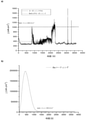
図2は、3種類のコーティングの試験結果を示す。明らかに、腐食電流が、コーティングの種類と関連していた。導電性コーティング材料(実線の曲線、図2(a))は、1時間以内に局所的な溶解を示し、大きい電流スパイクが見られた。これは、コーティングが時間と共に分解していたことを示唆する。 FIG. 2 shows the test results of three types of coatings. Obviously, the corrosion current was associated with the type of coating. The conductive coating material (solid curve, FIG. 2 (a)) showed local dissolution within 1 hour and large current spikes were seen. This suggests that the coating had decomposed over time.
他方で、スズコーティングは、完全に異なる挙動を示した。すなわち、大きい溶解ピークが最初に見られ(図2(b)の点線の曲線)、約2000秒後に電流が非常に低い値に急激に減少し、その後、「時間」軸を超え、まだより多くの正電流まで増加するが、カソードになった。これは、2000秒以内にほぼ半分のコーティング溶解し、一部酸化物層が形成された明らかな証拠であった。この時間の後、溶解速度は無視できるが、時間とともに依然として増加した。拡張腐食促進試験は、室温(R.T.)と80℃との間の温度サイクルの3.5日後に、腐食電流がnA/cm-2から、DoE目標をはるかに上回って大きい値まで増加したことを示した。 On the other hand, the tin coating behaved completely differently. That is, a large dissolution peak is first seen (dotted curve in FIG. 2 (b)), and after about 2000 seconds the current drops sharply to a very low value, then crosses the "time" axis and is still more. It increased to the positive current of, but became the cathode. This was clear evidence that almost half of the coating melted within 2000 seconds and a partial oxide layer was formed. After this time, the dissolution rate was negligible, but still increased over time. In the extended corrosion acceleration test, after 3.5 days of the temperature cycle between room temperature (RT) and 80 ° C., the corrosion current increased from nA / cm -2 to a large value well above the DoE target. I showed that I did.
導電性複合コーティング(図2(a)の破線曲線)は、最適な腐食電流を示し、電流スパイクがまったく存在せず(局所的劣化なし)、曲線の傾きが時間と共に減少した。 The conductive composite coating (dashed curve in FIG. 2A) showed optimum corrosion current, no current spikes (no local degradation), and the slope of the curve decreased over time.
コーティングの腐食の調査をさらに延長した。試験時間をはるかに長くし、コーティングの不具合が見られる(腐食電流密度がDoE目標約1μAcm-2未満を超える)まで、温度をR.T.と80℃との間で、それぞれの温度で一定時間(24または2時間)保持しながら循環させた。前述と同様に、使用した試験溶液は、1M Na2SO4,pH3であった。溶液は脱気しなかった。電位はSHEに対して+0.6Vになるようにし、この電位で24時間、各温度で保持した。 Further extension of the investigation of coating corrosion. The test time was much longer and the temperature was increased until coating defects were observed (corrosion current densities exceeded the DoE target of about 1 μA cm -2 ). T. And 80 ° C., each temperature was kept for a certain period of time (24 or 2 hours) and circulated. Similar to the above, the test solution used was 1M Na 2 SO 4 , pH 3. The solution did not degas. The potential was set to +0.6 V with respect to SHE, and the potential was maintained at each temperature for 24 hours.
上述したように、金属コーティングは、温度循環の腐食促進試験の下で3.5日のみ持続した。他方で、導電性コーティング材料層では、初期の溶解/酸化物形成を記録せず、腐食電流密度の増加が時間と共に見られた(図3参照)。120時間後に不具合が見られた。 As mentioned above, the metal coating lasted only 3.5 days under the temperature circulation corrosion acceleration test. On the other hand, in the conductive coating material layer, initial dissolution / oxide formation was not recorded and an increase in corrosion current density was observed over time (see FIG. 3). A defect was seen after 120 hours.
金属と有機コーティングとを一緒に組み合わせて導電性複合コーティングを形成することで、長期腐食促進試験(コーティングをさらにより厳しい条件に曝すために2時間ごとに温度を循環させる)を行った結果が良好であった(図4)参照。9日後、腐食増加の重大な兆候はなく、腐食電流の大きさがDoE目標よりはるかに下であった(DoE目標は図4に示される)。負の腐食電流密度は、コーティングのカソード作用、すなわちコーティングがこの電位で腐食していないことを示す。 Good results from long-term corrosion acceleration tests (circulating temperature every 2 hours to expose the coating to even more stringent conditions) by combining metal and organic coatings together to form a conductive composite coating. See (Fig. 4). After 9 days, there were no significant signs of increased corrosion and the magnitude of the corrosion current was well below the DoE target (DoE target is shown in Figure 4). Negative corrosion current densities indicate the cathodic action of the coating, i.e., the coating is not corroded at this potential.
金属と有機コーティングとの組み合わせは、相乗効果を示し、コーティングは腐食促進試験の9日以内に損なわれなかった。当該試験は、正常なPEM燃料電池の動作のほぼ1年に等しく、一方で、単層のコーティングはそのような条件下でむしろ速く劣化した。 The combination of metal and organic coating showed a synergistic effect and the coating was not compromised within 9 days of the corrosion acceleration test. The test was equivalent to almost a year of normal PEM fuel cell operation, while the monolayer coating deteriorated rather quickly under such conditions.
実施例3-多層コーティング
本実施例では、導電性コーティング材料を含む2層とスズを含む2層とを含む複合コーティングをはるかに良好な性能のために調製した。複合コーティングを図1(b)に示す。該複合コーティングは、電着したSn層に続いて、導電性コーティング材料層のスクリーン印刷の後、Sn-6wt%Sb合金の電着および最終導電性コーティング材料層を含む。全体の厚さは最大約40μmであった。
Example 3-Multilayer Coating In this example, a composite coating containing two layers containing a conductive coating material and two layers containing tin was prepared for much better performance. The composite coating is shown in FIG. 1 (b). The composite coating comprises an electrodeposited Sn layer followed by screen printing of the conductive coating material layer, followed by electrodeposition of the Sn-6 wt% Sb alloy and a final conductive coating material layer. The total thickness was up to about 40 μm.
腐食試験
コーティングの性能を、1M Na2SO4,pH3を含む溶液での促進腐食試験で再び試験し、腐食電流がDoE目標を超えるまで、温度をR.T.と80℃との間で2hごとに循環させた。溶液は脱気しなかった。電位をSHEに対して+0.6Vとなるようにし、この電位で1時間保持した。コーティングの挙動を図5に示す。腐食電流密度は、18日を超えて非常に良好な挙動を示した。電流密度が時間と共に増加したが、DoE目標を超えなかった。
Corrosion test The performance of the coating was retested in an accelerated corrosion test with a solution containing 1M Na 2 SO 4 , pH 3 and the temperature was increased until the corrosion current exceeded the DoE target. T. And 80 ° C. were circulated every 2 hours. The solution did not degas. The potential was set to +0.6 V with respect to SHE and held at this potential for 1 hour. The behavior of the coating is shown in FIG. The corrosion current density showed very good behavior over 18 days. The current density increased over time but did not exceed the DoE target.
明らかに、そのようなコーティングの構造が、低い接触抵抗の維持と同時に非常に良好な腐食バリアを示した。実際、コーティングのそのような群の接触抵抗は約1mΩcm2未満であった。 Obviously, the structure of such a coating showed a very good corrosion barrier as well as maintaining low contact resistance. In fact, the contact resistance of such groups of coatings was less than about 1 mΩcm 2 .
本発明の実施形態を説明したが、これらの実施形態は例示に過ぎない。当然ながら、説明した実施形態のバリエーションも本発明の範囲内でなし得る。 Although embodiments of the present invention have been described, these embodiments are merely examples. Of course, variations of the embodiments described may also be made within the scope of the present invention.
Claims (14)
元素炭素とアゾール含有腐食防止剤とを含む導電性コーティング材料を含む層と、スズの層、あるいはニッケル、アンチモン、インジウムまたはガリウムの1つ以上とスズとの二元もしくは三元スズ合金の層、あるいはスズおよび前記二元もしくは三元スズ合金の層とを含む導電性複合コーティングと、
を含む被覆した物品を含み、
前記スズの層、あるいは前記二元もしくは三元スズ合金の層、あるいは前記スズおよび前記二元もしくは三元スズ合金の層は、前記基板と直接接触しており、
前記導電性コーティング材料を含む層は、前記スズの層、あるいは前記二元もしくは三元スズ合金の層、あるいは前記スズおよび前記二元もしくは三元スズ合金の層の上にあり、
a)前記導電性コーティング材料を含む層が1~50μm厚さであり、かつ/または
b)前記スズの層、あるいは前記二元もしくは三元スズ合金の層、あるいは前記スズおよび前記二元もしくは三元スズ合金の層が1~20μm厚さであることを特徴とする電気化学的装置。 With the board
A layer containing a conductive coating material containing elemental carbon and an azole-containing corrosion inhibitor, a tin layer, or a binary or ternary tin alloy layer of one or more of nickel, antimony, indium or gallium and tin. Alternatively, a conductive composite coating comprising tin and a layer of said binary or ternary tin alloy.
Including covered articles, including
The tin layer, or the binary or ternary tin alloy layer, or the tin and the binary or ternary tin alloy layer is in direct contact with the substrate.
The layer containing the conductive coating material is on top of the tin layer, or the binary or ternary tin alloy layer, or the tin and the binary or ternary tin alloy layer .
a) The layer containing the conductive coating material is 1 to 50 μm thick and / or
b) An electrochemical apparatus characterized in that the tin layer, the binary or ternary tin alloy layer, or the tin and the binary or ternary tin alloy layer is 1 to 20 μm thick. ..
元素炭素とアゾール含有腐食防止剤とを含む導電性コーティング材料を含む2層以上の層と、
スズの層、あるいはニッケル、アンチモン、インジウムまたはガリウムの1つ以上とスズとの二元もしくは三元スズ合金の層、あるいはスズおよび前記二元もしくは三元スズ合金の層の2層以上の層と、
を含む請求項1に記載の電気化学的装置。 The conductive composite coating
Two or more layers containing a conductive coating material containing elemental carbon and an azole-containing corrosion inhibitor, and
A tin layer, or a binary or ternary tin alloy layer of one or more of nickel, antimony, indium or gallium and tin, or two or more layers of tin and the binary or ternary tin alloy layer. ,
The electrochemical device according to claim 1.
前記基板の表面上に、スズの層、あるいはニッケル、アンチモン、インジウムまたはガリウムの1つ以上とスズとの二元もしくは三元スズ合金の層、あるいはスズおよび前記二元もしくは三元スズ合金の層を堆積させるステップと、
前記スズの層、前記二元もしくは三元スズ合金の層、あるいは前記スズおよび前記二元もしくは三元スズ合金の層上に元素炭素とアゾール含有腐食防止剤とを含む導電性コーティング材料を含む層を堆積させるステップと、
を含むことを特徴とする電気化学的装置用の被覆した物品を提供する方法。 With the steps to prepare the board;
A layer of tin, or a layer of a binary or ternary tin alloy of one or more of nickel, antimony, indium or gallium and tin, or a layer of tin and the binary or ternary tin alloy on the surface of the substrate. And the steps to deposit
A layer containing a conductive coating material containing elemental carbon and an azole-containing corrosion inhibitor on the tin layer, the binary or ternary tin alloy layer, or the tin and the binary or ternary tin alloy layer. And the steps to deposit
A method of providing a coated article for an electrochemical device comprising.
前記スズのさらなる層、あるいは前記二元もしくは三元スズ合金のさらなる層、あるいは前記スズおよび前記二元もしくは三元スズ合金のさらなる層上に元素炭素とアゾール含有腐食防止剤とを含む導電性コーティング材料を含むさらなる層を前記基板の前記表面上に堆積させるステップと、
をさらに含む請求項12に記載の電気化学的装置用の被覆した物品を提供する方法。 A further layer of tin, or a binary or ternary tin alloy of tin with one or more of nickel, antimony, indium or gallium, on a layer containing a conductive coating material containing the elemental carbon and an azole-containing corrosion inhibitor. , Or a step of depositing a further layer of tin and the binary or ternary tin alloy.
A conductive coating containing elemental carbon and an azole-containing corrosion inhibitor on a further layer of the tin, or a further layer of the binary or ternary tin alloy, or a further layer of the tin and the binary or ternary tin alloy. A step of depositing an additional layer of material on the surface of the substrate,
12. The method of providing a coated article for an electrochemical device according to claim 12 .
Applications Claiming Priority (3)
| Application Number | Priority Date | Filing Date | Title |
|---|---|---|---|
| GB1610144.6A GB2551191B (en) | 2016-06-10 | 2016-06-10 | Electrically conductive composite coating with azole corrosion inhibitor |
| GB1610144.6 | 2016-06-10 | ||
| PCT/GB2017/051697 WO2017212295A1 (en) | 2016-06-10 | 2017-06-09 | Corrosion protection coating |
Publications (3)
| Publication Number | Publication Date |
|---|---|
| JP2019526147A JP2019526147A (en) | 2019-09-12 |
| JP2019526147A5 JP2019526147A5 (en) | 2020-02-06 |
| JP7009397B2 true JP7009397B2 (en) | 2022-02-10 |
Family
ID=56894792
Family Applications (1)
| Application Number | Title | Priority Date | Filing Date |
|---|---|---|---|
| JP2018564842A Active JP7009397B2 (en) | 2016-06-10 | 2017-06-09 | Anti-corrosion coating |
Country Status (10)
| Country | Link |
|---|---|
| US (1) | US20190148741A1 (en) |
| EP (1) | EP3469646B1 (en) |
| JP (1) | JP7009397B2 (en) |
| KR (1) | KR102379291B1 (en) |
| CN (1) | CN109478656B (en) |
| CA (1) | CA3026384C (en) |
| ES (1) | ES2863237T3 (en) |
| GB (1) | GB2551191B (en) |
| WO (1) | WO2017212295A1 (en) |
| ZA (1) | ZA201808560B (en) |
Families Citing this family (14)
| Publication number | Priority date | Publication date | Assignee | Title |
|---|---|---|---|---|
| DE102018204378A1 (en) * | 2018-03-22 | 2019-09-26 | Audi Ag | Determination of the insulation resistance of a fuel cell system |
| JP7006481B2 (en) * | 2018-04-23 | 2022-02-10 | トヨタ自動車株式会社 | Fuel cell separator |
| US11214693B2 (en) * | 2019-08-09 | 2022-01-04 | The Boeing Company | Electrically conductive coating compositions with corrosion resistance |
| CN112341848A (en) * | 2020-11-05 | 2021-02-09 | 上海理工大学 | Graphene coating and preparation method of graphene conductive corrosion-resistant coating |
| DE102020130695A1 (en) * | 2020-11-20 | 2022-05-25 | Schaeffler Technologies AG & Co. KG | Component of an electrochemical cell and electrochemical cells |
| DE102020130693A1 (en) * | 2020-11-20 | 2022-05-25 | Schaeffler Technologies AG & Co. KG | Component for an electrochemical cell, as well as a redox flow cell, fuel cell and electrolyser |
| DE102020130694A1 (en) | 2020-11-20 | 2022-05-25 | Schaeffler Technologies AG & Co. KG | Component for an electrochemical cell, as well as a redox flow cell, fuel cell and electrolyser |
| DE102022112319A1 (en) | 2021-06-30 | 2023-01-05 | Schaeffler Technologies AG & Co. KG | Component for an electrochemical cell, as well as a redox flow cell, fuel cell and electrolyser |
| US20240322192A1 (en) | 2021-06-30 | 2024-09-26 | Schaeffler Technologies AG & Co. KG | Component for an electrochemical cell, redox flow cell, and electrolyser |
| DE102021128468B3 (en) * | 2021-11-02 | 2022-10-06 | Schaeffler Technologies AG & Co. KG | Layer system, electrode plate with such a layer system, method for their production, and fuel cell, electrolyzer or redox flow cell |
| KR102537766B1 (en) * | 2022-09-21 | 2023-05-31 | 주식회사 아젠컴 | Integrated circuit chip for smart card, manufacturing method thereof, and smart card including integrated circuit chip |
| US12431260B2 (en) * | 2022-09-23 | 2025-09-30 | Caterpillar Inc. | High-velocity air-fuel coatings for conductor corrosion resistance |
| WO2024183856A1 (en) | 2023-03-03 | 2024-09-12 | Schaeffler Technologies AG & Co. KG | Component for an electrochemical cell, redox flow cell, fuel cell, and electrolyser |
| DE102024105383A1 (en) | 2023-03-03 | 2024-09-05 | Schaeffler Technologies AG & Co. KG | Component for an electrochemical cell, as well as redox flow cell, fuel cell and electrolyzer |
Citations (7)
| Publication number | Priority date | Publication date | Assignee | Title |
|---|---|---|---|---|
| JP2005166442A (en) | 2003-12-02 | 2005-06-23 | Matsushita Electric Ind Co Ltd | Energy device and manufacturing method thereof |
| JP2006044233A (en) | 2004-06-23 | 2006-02-16 | Ormecon Gmbh | Article with electrically conductive polymer coating and manufacturing method therefor |
| JP2006127939A (en) | 2004-10-29 | 2006-05-18 | Sumitomo Electric Ind Ltd | Electrical conductor parts and manufacturing method thereof |
| US20090061184A1 (en) | 2007-08-31 | 2009-03-05 | United Technologies Corporation | Processes for Applying a Conversion Coating with Conductive Additive(S) and the Resultant Coated Articles |
| JP2012082383A (en) | 2010-09-15 | 2012-04-26 | Nitto Denko Corp | Paste composition and wiring circuit board |
| JP2012153800A (en) | 2011-01-26 | 2012-08-16 | Nitto Denko Corp | Paste composition, and wiring circuit board |
| WO2015104999A1 (en) | 2014-01-07 | 2015-07-16 | 古河電気工業株式会社 | Electrolytic copper foil, negative electrode for lithium ion secondary battery, lithium ion secondary battery, printed wiring board, and electromagnetic shielding material |
Family Cites Families (16)
| Publication number | Priority date | Publication date | Assignee | Title |
|---|---|---|---|---|
| JPS59227448A (en) * | 1983-06-08 | 1984-12-20 | 株式会社村田製作所 | Corrosion protective structure of metal |
| JPH06333417A (en) * | 1993-05-21 | 1994-12-02 | Hitachi Chem Co Ltd | Conductive paste |
| JPH07262822A (en) * | 1994-03-23 | 1995-10-13 | Hitachi Chem Co Ltd | Conductive paste |
| WO1996024938A1 (en) * | 1995-02-08 | 1996-08-15 | Hitachi Chemical Co., Ltd. | Composite conductive powder, conductive paste, method of producing conductive paste, electric circuit and method of fabricating electric circuit |
| JP2000273317A (en) * | 1999-02-12 | 2000-10-03 | Natl Starch & Chem Investment Holding Corp | Electrically stable conductive and resistive materials for electronic devices |
| AU2003264403A1 (en) * | 2003-09-10 | 2005-04-06 | Mitsubishi Plastics, Inc. | Fuel cell separator |
| US7211204B2 (en) * | 2003-12-12 | 2007-05-01 | Electrochemicals, Inc. | Additives to stop copper attack by alkaline etching agents such as ammonia and monoethanol amine (MEA) |
| KR20050081252A (en) * | 2004-02-13 | 2005-08-18 | 고경현 | Porous metal coated member and manufacturing method thereof using cold spray |
| ATE455373T1 (en) * | 2006-06-08 | 2010-01-15 | Eveready Battery Inc | TIN-PLATED ANODE HOUSINGS FOR ALKALINE BATTERIES |
| CN102017254A (en) * | 2008-02-27 | 2011-04-13 | 因派科特涂料公司 | Electrode with a coating, method in production thereof and use of a material |
| US9340697B2 (en) * | 2009-08-14 | 2016-05-17 | Nano-C, Inc. | Solvent-based and water-based carbon nanotube inks with removable additives |
| CN102468490B (en) * | 2010-11-19 | 2014-04-16 | 中国科学院金属研究所 | Surface chromium carbide/graphite composite coating for vanadium redox flow battery stainless steel bipolar plate |
| CN102286271A (en) * | 2011-09-19 | 2011-12-21 | 鞍钢集团矿业公司 | Mining automobile engine coolant and preparation method thereof |
| CN103319954B (en) * | 2013-07-12 | 2014-10-01 | 珠海市乐通化工股份有限公司 | Conductive graphene printing ink and preparation method thereof |
| CN103756534A (en) * | 2013-12-27 | 2014-04-30 | 吴江市东泰电力特种开关有限公司 | Conductive anti-corrosion coating and preparation method thereof |
| US9381369B2 (en) * | 2014-02-06 | 2016-07-05 | Cardiac Pacemakers, Inc. | Battery for use with medical devices |
-
2016
- 2016-06-10 GB GB1610144.6A patent/GB2551191B/en not_active Expired - Fee Related
-
2017
- 2017-06-09 CN CN201780036113.9A patent/CN109478656B/en active Active
- 2017-06-09 KR KR1020197000641A patent/KR102379291B1/en active Active
- 2017-06-09 EP EP17730250.2A patent/EP3469646B1/en active Active
- 2017-06-09 JP JP2018564842A patent/JP7009397B2/en active Active
- 2017-06-09 CA CA3026384A patent/CA3026384C/en active Active
- 2017-06-09 WO PCT/GB2017/051697 patent/WO2017212295A1/en not_active Ceased
- 2017-06-09 ES ES17730250T patent/ES2863237T3/en active Active
- 2017-06-09 US US16/307,285 patent/US20190148741A1/en not_active Abandoned
-
2018
- 2018-12-19 ZA ZA2018/08560A patent/ZA201808560B/en unknown
Patent Citations (7)
| Publication number | Priority date | Publication date | Assignee | Title |
|---|---|---|---|---|
| JP2005166442A (en) | 2003-12-02 | 2005-06-23 | Matsushita Electric Ind Co Ltd | Energy device and manufacturing method thereof |
| JP2006044233A (en) | 2004-06-23 | 2006-02-16 | Ormecon Gmbh | Article with electrically conductive polymer coating and manufacturing method therefor |
| JP2006127939A (en) | 2004-10-29 | 2006-05-18 | Sumitomo Electric Ind Ltd | Electrical conductor parts and manufacturing method thereof |
| US20090061184A1 (en) | 2007-08-31 | 2009-03-05 | United Technologies Corporation | Processes for Applying a Conversion Coating with Conductive Additive(S) and the Resultant Coated Articles |
| JP2012082383A (en) | 2010-09-15 | 2012-04-26 | Nitto Denko Corp | Paste composition and wiring circuit board |
| JP2012153800A (en) | 2011-01-26 | 2012-08-16 | Nitto Denko Corp | Paste composition, and wiring circuit board |
| WO2015104999A1 (en) | 2014-01-07 | 2015-07-16 | 古河電気工業株式会社 | Electrolytic copper foil, negative electrode for lithium ion secondary battery, lithium ion secondary battery, printed wiring board, and electromagnetic shielding material |
Also Published As
| Publication number | Publication date |
|---|---|
| CA3026384A1 (en) | 2017-12-14 |
| KR20190017914A (en) | 2019-02-20 |
| ZA201808560B (en) | 2021-03-31 |
| EP3469646A1 (en) | 2019-04-17 |
| JP2019526147A (en) | 2019-09-12 |
| WO2017212295A1 (en) | 2017-12-14 |
| GB201610144D0 (en) | 2016-07-27 |
| US20190148741A1 (en) | 2019-05-16 |
| CA3026384C (en) | 2023-08-29 |
| CN109478656A (en) | 2019-03-15 |
| GB2551191B (en) | 2020-01-15 |
| ES2863237T3 (en) | 2021-10-11 |
| GB2551191A (en) | 2017-12-13 |
| KR102379291B1 (en) | 2022-03-28 |
| EP3469646B1 (en) | 2021-01-20 |
| CN109478656B (en) | 2023-08-29 |
Similar Documents
| Publication | Publication Date | Title |
|---|---|---|
| JP7009397B2 (en) | Anti-corrosion coating | |
| Yi et al. | Corrosion and interfacial contact resistance of 316L stainless steel coated with magnetron sputtered ZrN and TiN in the simulated cathodic environment of a proton-exchange membrane fuel cell | |
| Wei et al. | Design principle of insulating surface protective layers for metallic Zn anodes: a case study of ZrO2 | |
| Bi et al. | Multilayered Zr–C/aC film on stainless steel 316L as bipolar plates for proton exchange membrane fuel cells | |
| Fashu et al. | Influence of electrodeposition conditions on the microstructure and corrosion resistance of Zn–Ni alloy coatings from a deep eutectic solvent | |
| Zhang et al. | Corrosion behavior of TiN-coated stainless steel as bipolar plate for proton exchange membrane fuel cell | |
| Lu et al. | Characterization of Ti3SiC2-coating on stainless steel bipolar plates in simulated proton exchange membrane fuel cell environments | |
| Lin et al. | An investigation of coated aluminium bipolar plates for PEMFC | |
| JP5338607B2 (en) | Stainless steel plate for separator of polymer electrolyte fuel cell and polymer electrolyte fuel cell using the same | |
| Zhang et al. | Performance of Ti–Ag-deposited titanium bipolar plates in simulated unitized regenerative fuel cell (URFC) environment | |
| Tian et al. | Corrosion resistance and interfacial contact resistance of TiN coated 316L bipolar plates for proton exchange membrane fuel cell | |
| Gao et al. | Electrochemical characteristics and interfacial contact resistance of Ni-P/TiN/PTFE coatings on Ti bipolar plates | |
| Chien et al. | Microstructure and properties of carbon–sulfur-containing chromium deposits electroplated in trivalent chromium baths with thiosalicylic acid | |
| Nikam et al. | Corrosion resistant low temperature carburized SS 316 as bipolar plate material for PEMFC application | |
| Li et al. | Performance of tantalum modified 316L stainless steel bipolar plate for proton exchange membrane fuel cell | |
| JP2008045205A (en) | Stainless steel anode for alkaline water electrolysis and method for producing the same | |
| Gonzalez-Rodriguez et al. | Improvement on the corrosion protection of conductive polymers in pemfc environmets by adhesives | |
| Sievers et al. | Corrosion-protection of moulded graphite conductive plastic bipolar plates in PEM electrolysis by plasma processing | |
| JP3961434B2 (en) | Manufacturing method of fuel cell separator | |
| Huang et al. | Improved electrochemical performance of Zn–air secondary batteries via novel organic additives | |
| Wu et al. | Unveiling the reaction mechanism of aluminum and its alloy anode in aqueous aluminum cells | |
| Rosalbino et al. | Electrochemical corrosion behaviour of Sn–Ag–Cu (SAC) eutectic alloy in a chloride containing environment | |
| Cui et al. | Electrochemical properties of niobium modified AISI316L stainless steel bipolar plates for direct formic acid fuel cell | |
| Wang et al. | Influence of sodium alginate and chromate on aluminum corrosion in simulated HVDC cooling water | |
| JP2018022598A (en) | Conductive paste |
Legal Events
| Date | Code | Title | Description |
|---|---|---|---|
| A521 | Request for written amendment filed |
Free format text: JAPANESE INTERMEDIATE CODE: A523 Effective date: 20191220 |
|
| A621 | Written request for application examination |
Free format text: JAPANESE INTERMEDIATE CODE: A621 Effective date: 20191220 |
|
| A977 | Report on retrieval |
Free format text: JAPANESE INTERMEDIATE CODE: A971007 Effective date: 20201117 |
|
| A131 | Notification of reasons for refusal |
Free format text: JAPANESE INTERMEDIATE CODE: A131 Effective date: 20201208 |
|
| A521 | Request for written amendment filed |
Free format text: JAPANESE INTERMEDIATE CODE: A523 Effective date: 20210304 |
|
| A131 | Notification of reasons for refusal |
Free format text: JAPANESE INTERMEDIATE CODE: A131 Effective date: 20210706 |
|
| A521 | Request for written amendment filed |
Free format text: JAPANESE INTERMEDIATE CODE: A523 Effective date: 20211005 |
|
| TRDD | Decision of grant or rejection written | ||
| A01 | Written decision to grant a patent or to grant a registration (utility model) |
Free format text: JAPANESE INTERMEDIATE CODE: A01 Effective date: 20220104 |
|
| A61 | First payment of annual fees (during grant procedure) |
Free format text: JAPANESE INTERMEDIATE CODE: A61 Effective date: 20220112 |
|
| R150 | Certificate of patent or registration of utility model |
Ref document number: 7009397 Country of ref document: JP Free format text: JAPANESE INTERMEDIATE CODE: R150 |
|
| S531 | Written request for registration of change of domicile |
Free format text: JAPANESE INTERMEDIATE CODE: R313531 |
|
| R350 | Written notification of registration of transfer |
Free format text: JAPANESE INTERMEDIATE CODE: R350 |
|
| R250 | Receipt of annual fees |
Free format text: JAPANESE INTERMEDIATE CODE: R250 |