JP7008949B2 - Oil-water separation tank, oil-water separation device and separation tank connecting pipe - Google Patents
Oil-water separation tank, oil-water separation device and separation tank connecting pipe Download PDFInfo
- Publication number
- JP7008949B2 JP7008949B2 JP2017157197A JP2017157197A JP7008949B2 JP 7008949 B2 JP7008949 B2 JP 7008949B2 JP 2017157197 A JP2017157197 A JP 2017157197A JP 2017157197 A JP2017157197 A JP 2017157197A JP 7008949 B2 JP7008949 B2 JP 7008949B2
- Authority
- JP
- Japan
- Prior art keywords
- oil
- separation tank
- water separation
- side wall
- contact portion
- Prior art date
- Legal status (The legal status is an assumption and is not a legal conclusion. Google has not performed a legal analysis and makes no representation as to the accuracy of the status listed.)
- Active
Links
Images


Description
本発明は、油の混入した水から、油を回収するための油水分離槽、具体的には、ガソリンスタンド、洗車場、油を利用する工場などで用いられるのに適した油水分離槽およびそれを用いた油水分離装置に関するものである。 The present invention is an oil-water separation tank for recovering oil from water mixed with oil, specifically, an oil-water separation tank suitable for use in gas stations, car wash stations, factories that use oil, and the like. It relates to an oil-water separation device using.
油水分離施設の形成には、油水分離槽が用いられる。油水分離槽は、油が混入した排水を滞留させて、油と水との比重の差により、油水を分離し、上層に溜まった油分を除去するために用いられる。
油水分離施設としては、施工現場にて作成するタイプのもの、あらかじめ作成した油水分離槽を設置場所に運搬し、油水分離施設を構築するものがある。あらかじめ作成した油水分離槽を用いることにより、施工期間を短縮できるという利点がある。
このような施工に用いられる油水分離槽としては、実用新案登録2597949公報(特許文献1)のようなプレキャスト式油水分離槽がある。このプレキャスト式油水分離槽は、上端および下端双方の少なくとも一部が開放された略筒型のコンクリート製の外枠と、この外枠の内部に設けられた少なくとも1枚のコンクリート製の仕切壁によって仕切られた複数の区画と、隣接するこれら複数の区画を連通するように前記仕切壁に埋設された該仕切壁の壁厚と略長さの等しい樹脂製の連通管とを有している。
An oil-water separation tank is used to form the oil-water separation facility. The oil-water separation tank is used to retain the wastewater mixed with oil, separate the oil-water by the difference in the specific gravity of the oil and the water, and remove the oil content accumulated in the upper layer.
As the oil-water separation facility, there are a type created at the construction site and a type in which the oil-water separation tank prepared in advance is transported to the installation site to construct the oil-water separation facility. By using the oil-water separation tank created in advance, there is an advantage that the construction period can be shortened.
As an oil-water separation tank used for such construction, there is a precast type oil-water separation tank as in Utility Model Registration No. 25979949 (Patent Document 1). This precast oil-water separation tank has a substantially tubular concrete outer frame in which at least a part of both the upper end and the lower end is open, and at least one concrete partition wall provided inside the outer frame. It has a plurality of partitioned compartments and a resin communication pipe having a wall thickness and substantially the same length as the partition wall embedded in the partition wall so as to communicate the plurality of adjacent compartments.
特許文献1の油水分離槽では、工場でプレキャストされた略直方体のコンクリート製の外枠1から形成されており、その内部は同時にプレキャストされた3枚のコンクリート製の仕切壁7a~7cによって仕切られている。この仕切り壁7a~7cは、外枠1の長手方向の側壁2aと2bとを接続するように、外枠1の上端4から下端5にわたって形成されている。この仕切壁7a~7cによって、4つの均等な大きさの区画15a~15dが構成されている。外枠1の上端4および下端5には底面および上面が形成されていないので、それぞれの区画15a~15dの上端および下端は開口された儘である。この外枠1の上部に、鉄製の蓋掛り枠20がレベル調整機構30を介して接続され、この蓋掛り枠20に各ピットに対応した4枚の鉄製の蓋29が設置されるものとなっている。
The oil-water separation tank of
特許文献1の油水分離槽では、4つの区画(分離室)を備えており、全体として大きく、運搬、運搬後の設置場所への配置作業は容易なものではない。
本願発明者は、運搬、施工場所への設置作業を容易なものとするために、油水分離槽を小型化することを検討し、具体的には、内部に形成される分離槽を3以下とすることにより、小型化可能であると考えた。しかし、このような小型化油水分離槽では、1つの分離槽にて行える油水分離機能には限界があり、確実な油水分離を行うためには、複数の油水分離槽を連接することが必要であると考えた。そして、複数の油水分離槽を連接する場合には、分離槽間における漏水を確実に防止できること、漏水のない分離槽連結を容易に行うことができることが必要であることを知見した。
The oil-water separation tank of
The inventor of the present application has considered downsizing the oil-water separation tank in order to facilitate transportation and installation work at the construction site. Specifically, the number of separation tanks formed inside is 3 or less. By doing so, we thought that it would be possible to reduce the size. However, in such a miniaturized oil-water separation tank, there is a limit to the oil-water separation function that can be performed in one separation tank, and it is necessary to connect a plurality of oil-water separation tanks in order to perform reliable oil-water separation. I thought there was. Then, it was found that when connecting a plurality of oil-water separation tanks, it is necessary to be able to reliably prevent water leakage between the separation tanks and to easily connect the separation tanks without water leakage.
本発明の目的は、複数の油水分離槽を連接して構成する油水分離施設に使用する油水分離槽であって、連接する油水分離槽間における漏水を確実に防止でき、かつ、分離槽連接を容易に行うことができる油水分離槽、それを用いた油水分離装置および分離槽連結管を提供するものである。 An object of the present invention is an oil-water separation tank used in an oil-water separation facility configured by connecting a plurality of oil-water separation tanks, which can surely prevent water leakage between the connected oil-water separation tanks and can connect the separation tanks. It provides an oil-water separation tank that can be easily performed, an oil-water separation device using the oil-water separation tank, and a separation tank connecting pipe.
上記目的を達成するものは、以下のものである。
(1) 油水分離槽と接続用油水分離槽とを連結して構成される油水分離装置に使用される油水分離槽であって、前記油水分離槽は、少なくとも1つの分離室と、前記分離室の流入側の側壁に設けられた第1の側壁開口部と、前記分離室の流出側の側壁に設けられた第2の側壁開口部と、前記第2の側壁開口部に装着された分離槽連結管とを備え、前記分離槽連結管は、前記第2の側壁開口部より前記分離室の底部側に延び、下部に第1の開口を有する管状本体と、前記管状本体と連通し、前記第2の側壁開口部より突出し、接続される前記接続用油水分離槽が備える側壁開口部より、前記接続用油水分離槽の分離室に進入可能な管状突出部と、前記油水分離槽の分離室の内壁に液密状態にて当接可能な第1の当接部と、前記管状突出部上を移動可能に設けられ、接続される前記接続用油水分離槽の前記側壁開口部の周縁部の内壁および前記管状突出部の外面に液密状態にて接触可能な第2の当接部と、前記第2の当接部の一方の面側に当接し、前記第2の当接部の他方の面側を前記接続用油水分離槽の前記側壁開口部の周縁部の内壁に押圧し、押圧状態にて固定するための固定部材を備え、さらに、前記固定部材および前記第2の当接部は、前記管状突出部に装脱可能となっている油水分離装置に使用される油水分離槽。
Those that achieve the above objectives are as follows.
(1) An oil-water separation tank used in an oil-water separation device configured by connecting an oil-water separation tank and a connection oil-water separation tank, wherein the oil-water separation tank has at least one separation chamber and the separation chamber . A first side wall opening provided on the side wall on the inflow side, a second side wall opening provided on the side wall on the outflow side of the separation chamber, and a separation tank mounted on the second side wall opening. The separation tank connecting pipe is provided with a connecting pipe, and the separation tank connecting pipe extends from the second side wall opening toward the bottom of the separation chamber, communicates with a tubular body having a first opening at the bottom, and communicates with the tubular body. A tubular protrusion that protrudes from the second side wall opening and can enter the separation chamber of the connection oil-water separation tank from the side wall opening of the connection oil-water separation tank to be connected, and a separation chamber of the oil-water separation tank. A first contact portion that can be contacted with the inner wall of the inner wall in a liquidtight state, and a peripheral edge portion of the side wall opening of the connecting oil-water separation tank that is movably provided and connected on the tubular protrusion. A second contact portion that can contact the inner wall and the outer surface of the tubular protrusion in a liquidtight state, and one surface side of the second contact portion, and the other of the second contact portion. A fixing member for pressing the surface side of the connecting oil-water separation tank against the inner wall of the peripheral edge of the side wall opening of the connecting oil-water separation tank and fixing the fixing member in the pressed state is provided, and the fixing member and the second contact portion are further provided. Is an oil-water separation tank used for an oil-water separation device that can be attached to and detached from the tubular protrusion.
(2) 前記油水分離槽は、上流側分離室と、下流側分離室と、前記上流側分離室の側壁に設けられた前記第1の側壁開口部と、前記油水分離槽内を複数の室に区分する仕切壁に設けられた仕切壁開口部と、前記下流側分離室の側壁に設けられた前記第2の側壁開口部と、前記仕切壁開口部に、液密に装着され、前記上流側分離室と前記下流側分離室とを連通する分離室間連通管とを備え、前記分離室間連通管は、前記仕切壁開口部より前記上流側分離室の底部方向に延び、下部に第1の開口を有する管状本体と、前記管状本体と連通し、前記下流側分離室の上部側にて開口する第2の開口を有する管状突出部とを備えている上記(1)に記載の油水分離装置に使用される油水分離槽。
(3) 前記油水分離槽は、上部開口部を有するプレキャストコンクリート製の槽本体と、前記上部開口部に載置された蓋とを備え、前記槽本体は、底板部と、前記底板部の環状周縁部より上方に延びる環状の側壁部と、前記上部開口部の内側に形成された蓋載置部とを備えるものである上記(1)または(2)に記載の油水分離装置に使用される油水分離槽。
(4) 前記分離槽連結管の前記管状本体と前記管状突出部は、連通し、かつ、両者の中心軸は、ほぼ直交するものとなっている上記(1)ないし(3)のいずれかに記載の油水分離装置に使用される油水分離槽。
(5) 前記第2の当接部は、前記固定部材と当接する一方の面側を有する当接板と、前記当接板の他方の面側に配置された環状シール部材を備え、前記環状シール部材は、押圧により内径が縮径するものとなっている上記(1)ないし(4)のいずれかに記載の油水分離装置に使用される油水分離槽。
(6) 前記分離槽連結管は、前記管状突出部に設けられた前記固定部材を装着するための装着用貫通孔を備え、前記固定部材は、固定部材本体と、前記固定部材本体の側面より外方に延び、かつ、前記装着用貫通孔に挿入可能かつ係合可能な装着部と、前記固定部材本体と螺合し、螺合の進行により、前記第2の当接部方向に移動可能な押圧部とを備えている上記(1)ないし(5)のいずれかに記載の油水分離装置に使用される油水分離槽。
(7) 前記分離槽連結管の前記装着用貫通孔は、前記分離槽連結管の中心軸に対して、ほぼ等角度に2つ以上設けられており、かつ、前記各装着用貫通孔に前記固定部材が装着されるものとなっている上記(6)に記載の油水分離槽。
(8) 前記分離槽連結管は、前記管状突出部の外面に設けられた雄側螺合部を備え、前記固定部材は、前記雄側螺合部と螺合可能な雌側螺合部を有し、前記固定部材は、螺合の進行により、前記第2の当接部方向に移動可能であり、かつ先端面が、前記第2の当接部に当接可能かつ押圧可能となっている上記(1)ないし(5)のいずれかに記載の油水分離装置に使用される油水分離槽。
(2) The oil-water separation tank has an upstream side separation chamber, a downstream side separation chamber, the first side wall opening provided on the side wall of the upstream side separation chamber, and a plurality of chambers in the oil-water separation tank. The partition wall opening provided in the partition wall divided into the above, the second side wall opening provided in the side wall of the downstream side separation chamber, and the partition wall opening are liquid-tightly attached to the upstream. A communication pipe between the separation chambers for communicating the side separation chamber and the downstream side separation chamber is provided, and the separation chamber communication pipe extends from the partition wall opening toward the bottom of the upstream side separation chamber and has a lower portion. The oily water according to (1) above, comprising a tubular body having an opening of 1 and a tubular protrusion having a second opening that communicates with the tubular body and opens on the upper side of the downstream separation chamber. An oil-water separation tank used for the separation device .
(3) The oil-water separation tank includes a precast concrete tank body having an upper opening and a lid placed on the upper opening, and the tank body has a bottom plate portion and an annular shape of the bottom plate portion. Used in the oil-water separation device according to (1) or (2) above, which includes an annular side wall portion extending above the peripheral edge portion and a lid mounting portion formed inside the upper opening portion. Oil-water separation tank.
(4) In any of the above (1) to (3), the tubular body of the separation tank connecting pipe and the tubular protrusion are communicated with each other, and the central axes of the two are substantially orthogonal to each other. The oil-water separation tank used in the described oil-water separation device .
(5) The second contact portion includes a contact plate having one surface side that comes into contact with the fixing member, and an annular seal member arranged on the other surface side of the contact plate, and the annular seal member. The oil-water separation tank used in the oil-water separation device according to any one of (1) to (4) above, wherein the seal member has an inner diameter that is reduced by pressing.
(6) The separation tank connecting pipe is provided with a mounting through hole for mounting the fixing member provided in the tubular protrusion, and the fixing member is from the fixing member main body and the side surface of the fixing member main body. The mounting portion that extends outward and can be inserted into and engaged with the mounting through hole is screwed with the fixing member main body, and can be moved toward the second contact portion by the progress of the screwing. An oil-water separation tank used in the oil-water separation device according to any one of (1) to (5) above, which is provided with a pressing portion.
(7) Two or more mounting through holes of the separation tank connecting pipe are provided at substantially the same angle with respect to the central axis of the separation tank connecting pipe, and the mounting through holes are provided with the above. The oil-water separation tank according to (6) above, to which a fixing member is mounted.
(8) The separation tank connecting pipe includes a male-side screw portion provided on the outer surface of the tubular protrusion, and the fixing member has a female-side screw portion that can be screwed with the male-side screw portion. The fixing member has and can move in the direction of the second contact portion by the progress of screwing, and the tip surface can contact and press the second contact portion. The oil-water separation tank used in the oil-water separation device according to any one of (1) to (5) above.
また、上記目的を達成するものは、以下のものである。
(9)上記(1)ないし(8)のいずれかに記載の前記油水分離槽を第1油水分離槽として備え、さらに、前記第1油水分離槽と連結される前記接続用油水分離槽として第2油水分離槽を備える油水分離装置であって、前記第2油水分離槽は、少なくとも1つの分離室と、前記側壁開口部として、前記分離室の流入側の側壁に設けられた第1の側壁開口部と、前記分離室の流出側の側壁に設けられた第2の側壁開口部とを備え、前記第1油水分離槽の前記分離槽連結管の前記管状突出部は、連結される前記第2油水分離槽の前記第1の側壁開口部より、前記分離室に進入可能であり、前記固定部材は、前記第2の当接部の一方の面側に当接し、前記第2の当接部の他方の面側を前記第2油水分離槽の前記第1の側壁開口部の周縁部の内壁に押圧可能であり、前記固定部材の押圧により、前記第2の当接部は、前記第2油水分離槽の前記第1の側壁開口部の周縁部の内壁および前記管状突出部の外面に液密状態にて接触可能であり、かつ、前記固定部材により、当該液密状態が維持可能である油水分離装置。
In addition, those that achieve the above objectives are as follows.
(9) The oil-water separation tank according to any one of (1) to (8) above is provided as a first oil-water separation tank, and further, as the connection oil- water separation tank connected to the first oil-water separation tank. An oil-water separation device including two oil-water separation tanks, wherein the second oil-water separation tank has at least one separation chamber and a first side wall provided as a side wall opening on the side wall on the inflow side of the separation chamber. The tubular protrusion of the separation tank connecting pipe of the first oil-water separation tank is connected to the first, which comprises an opening and a second side wall opening provided on the side wall on the outflow side of the separation chamber. 2 The separation chamber can be entered through the first side wall opening of the oil-water separation tank, and the fixing member abuts on one surface side of the second abutment portion, and the second abutment portion abuts. The other surface side of the portion can be pressed against the inner wall of the peripheral edge portion of the first side wall opening of the second oil-water separation tank, and by pressing the fixing member, the second contact portion is brought into the second contact portion. 2 The inner wall of the peripheral edge of the first side wall opening of the oil-water separation tank and the outer surface of the tubular protrusion can be contacted in a liquid-tight state, and the liquid-tight state can be maintained by the fixing member. An oil-water separator.
また、上記目的を達成するものは、以下のものである。
(10)第1油水分離槽と第2油水分離槽を連結するための分離槽連結管であって、前記分離槽連結管は、下方に延び、かつ下端部に第1の開口を有する管状本体と、前記管状本体の上部と連通し、かつ側部方向に延び、前記第1油水分離槽の側壁開口部を貫通可能かつ、接続される前記第2油水分離槽が備える側壁開口部より、前記第2油水分離槽内に進入可能な管状突出部と、前記管状突出部に被装され、前記第1油水分離槽の側壁開口部の周縁部の内壁に当接可能な第1の当接部と、前記管状突出部上を移動可能に設けられ、接続される前記第2油水分離槽の側壁開口部の周縁部の内壁および前記管状突出部の外面に液密状態にて接触可能な第2の当接部と、前記第2の当接部の一方の面側に当接し、前記第2の当接部の他方の面側を前記第2油水分離槽の側壁開口部の周縁部の内壁に押圧し、押圧状態にて固定するための固定部材とを備え、さらに、前記固定部材および前記第2の当接部は、前記管状突出部に装脱可能となっている分離槽連結管。
In addition, those that achieve the above objectives are as follows.
(10) A separation tank connecting pipe for connecting the first oil-water separation tank and the second oil-water separation tank, and the separation tank connecting pipe extends downward and has a first opening at the lower end. From the side wall opening provided in the second oil / water separation tank which communicates with the upper part of the tubular body and extends in the lateral direction, can penetrate the side wall opening of the first oil / water separation tank, and is connected. A tubular protrusion that can enter the second oil-water separation tank and a first contact portion that is covered with the tubular protrusion and can contact the inner wall of the peripheral edge of the side wall opening of the first oil-water separation tank. A second oil-water separation tank that is movably provided on the tubular protrusion and can be contacted in a liquidtight state with the inner wall of the peripheral edge of the side wall opening of the second oil-water separation tank and the outer surface of the tubular protrusion. The contact portion and the one surface side of the second contact portion are abutted, and the other surface side of the second contact portion is the inner wall of the peripheral edge portion of the side wall opening of the second oil-water separation tank. A separation tank connecting pipe that is provided with a fixing member for pressing and fixing in a pressed state, and further, the fixing member and the second contact portion can be attached to and detached from the tubular protrusion.
本発明の油水分離槽は、少なくとも2つの油水分離槽を連結して構成される油水分離装置に使用される油水分離槽である。油水分離槽は、少なくとも1つの分離室と、流入側の側壁に設けられた第1の側壁開口部と、流出側の側壁に設けられた第2の側壁開口部と、第2の側壁開口部に装着された分離槽連結管とを備える。分離槽連結管は、第2の側壁開口部より分離室の底部側に延び、下部に第1の開口を有する管状本体と、管状本体と連通し、第2の側壁開口部より突出し、接続される第2油水分離槽が備える第1の側壁開口部より、第2油水分離槽の分離室に進入可能な管状突出部と、油水分離槽の分離室の内壁に液密状態にて当接可能な第1の当接部と、管状突出部上を移動可能に設けられ、接続される第2油水分離槽の第1の側壁開口部の周縁部の内壁および前記管状突出部の外面に液密状態にて接触可能な第2の当接部と、第2の当接部の一方の面側に当接し、第2の当接部の他方の面側を第2油水分離槽の第1の側壁開口部の周縁部の内壁に押圧し、押圧状態にて固定するための固定部材を備え、さらに、固定部材および第2の当接部は、管状突出部に装脱可能となっている。 The oil-water separation tank of the present invention is an oil-water separation tank used in an oil-water separation device configured by connecting at least two oil-water separation tanks. The oil-water separation tank has at least one separation chamber, a first side wall opening provided on the side wall on the inflow side, a second side wall opening provided on the side wall on the outflow side, and a second side wall opening. It is equipped with a separation tank connecting pipe attached to. The separation tank connecting pipe extends from the second side wall opening to the bottom side of the separation chamber, communicates with the tubular body having the first opening at the bottom, and protrudes from the second side wall opening to be connected. From the opening of the first side wall of the second oil-water separation tank, the tubular protrusion that can enter the separation chamber of the second oil-water separation tank and the inner wall of the separation chamber of the oil-water separation tank can be in contact with each other in a liquidtight state. Liquid-tight on the inner wall of the peripheral edge of the first side wall opening of the second oil-water separation tank and the outer surface of the tubular protrusion, which are movably provided on the tubular protrusion and are connected to the first contact portion. The second contact portion that can be contacted in the state and the one surface side of the second contact portion are abutted, and the other surface side of the second contact portion is the first surface side of the second oil / water separation tank. A fixing member for pressing against the inner wall of the peripheral edge of the side wall opening and fixing in the pressed state is provided, and the fixing member and the second contact portion can be attached to and detached from the tubular protrusion.
このため、油水分離槽の分離槽連結管の管状突出部を第2油水分離槽の第1の側壁開口部に挿入させ、第2の当接部を管状突出部に装着し、続いて、固定部材を装着し、固定部材を操作し、固定部材により、第2の当接部を第2油水分離槽の第1の側壁開口部の周縁部の内壁に押圧し、押圧状態にて固定することにより、第2の当接部は、第2油水分離槽の第1の側壁開口部の周縁部の内壁および管状突出部の外面に液密状態にて接触した状態となり、また、第1の当接部は、油水分離槽の下流側分離室の内壁に液密状態にて当接した状態となるため、油水分離槽の下流側分離槽と第2油水分離槽の上流側分離槽を容易に液密状態にて連接させることができる。 Therefore, the tubular protrusion of the separation tank connecting pipe of the oil-water separation tank is inserted into the first side wall opening of the second oil-water separation tank, the second contact portion is attached to the tubular protrusion, and then fixed. The member is attached, the fixing member is operated, and the second contact portion is pressed against the inner wall of the peripheral portion of the first side wall opening of the second oil-water separation tank by the fixing member, and is fixed in the pressed state. As a result, the second contact portion comes into contact with the inner wall of the peripheral edge of the first side wall opening of the second oil-water separation tank and the outer surface of the tubular protrusion in a liquidtight state, and the first hit Since the contact part is in a state of being in contact with the inner wall of the downstream side separation chamber of the oil / water separation tank in a liquidtight state, the downstream side separation tank of the oil / water separation tank and the upstream side separation tank of the second oil / water separation tank can be easily separated. It can be connected in a liquidtight state.
また、本発明の油水分離装置は、上記の油水分離槽を第1油水分離槽とし、第1油水分離槽と連結される第2油水分離槽とを備え、第2油水分離槽は、少なくとも1つの分離室と、流入側の側壁に設けられた第1の側壁開口部と、流出側の側壁に設けられた第2の側壁開口部とを備え、第1油水分離槽の分離槽連結管の管状突出部は、連結される第2油水分離槽の第1の側壁開口部より、分離室に進入可能であり、固定部材は、第2の当接部の一方の面側に当接し、第2の当接部の他方の面側を側壁開口部の周縁部の内壁に押圧可能であり、固定部材の押圧により、第2の当接部は、第2油水分離槽の側壁開口部の周縁部の内壁および管状突出部の外面に液密状態にて接触可能であり、かつ、固定部材により、当該液密状態が維持可能となっている。 Further, the oil-water separation device of the present invention includes the above-mentioned oil-water separation tank as a first oil-water separation tank and a second oil-water separation tank connected to the first oil-water separation tank, and the second oil-water separation tank has at least one. The separation tank connecting pipe of the first oil-water separation tank is provided with two separation chambers, a first side wall opening provided on the side wall on the inflow side, and a second side wall opening provided on the side wall on the outflow side. The tubular protrusion can enter the separation chamber through the opening of the first side wall of the second oil-water separation tank to be connected, and the fixing member abuts on one surface side of the second contact portion, and the second The other surface side of the contact portion of 2 can be pressed against the inner wall of the peripheral edge portion of the side wall opening, and by pressing the fixing member, the second contact portion is formed on the peripheral edge of the side wall opening of the second oil / water separation tank. The inner wall of the portion and the outer surface of the tubular protrusion can be contacted in a liquid-tight state, and the liquid-tight state can be maintained by the fixing member.
このため、第1油水分離槽と第2油水分離槽は、分離槽連結管により、液密に連通し、かつその状態が維持可能である。また、第1油水分離槽と第2油水分離槽は、油水分離装置の設置場所において、分離槽連結管を操作することにより、容易に連結することができ、施工を短期間にて行うことができる。 Therefore, the first oil-water separation tank and the second oil-water separation tank can communicate with each other in a liquid-tight manner by the separation tank connecting pipe, and the state can be maintained. In addition, the first oil-water separation tank and the second oil-water separation tank can be easily connected by operating the separation tank connecting pipe at the installation location of the oil-water separation device, and the construction can be performed in a short period of time. can.
また、本発明の分離槽連結管は、2つの油水分離槽を連結するための分離槽連結管であって、分離槽連結管は、下方に延び、かつ下端部に第1の開口部を有する管状本体と、管状本体の上部と連通し、かつ側部方向に延び、油水分離槽の側壁開口部を貫通可能かつ、接続される第2油水分離槽が備える側壁開口部より、第2油水分離槽内に進入可能な管状突出部と、管状突出部に被装され、油水分離槽の側壁開口部の内壁に当接可能な第1の当接部と、管状突出部上を移動可能に設けられ、接続される第2油水分離槽の側壁開口部の内壁および管状突出部の外面に液密状態にて接触可能な第2の当接部と、第2の当接部の一方の面側に当接し、第2の当接部の他方の面側を第2油水分離槽の側壁開口部の周縁部の内壁に押圧し、押圧状態にて固定するための固定部材とを備え、さらに、固定部材および第2の当接部は、管状突出部に装脱可能となっている。
このため、この分離槽連結管を用いることにより、第1油水分離槽と第2油水分離槽を設置場所において、容易に連結することができ、短期間の油水分離装置の施工を可能とする。
Further, the separation tank connecting pipe of the present invention is a separation tank connecting pipe for connecting two oil-water separation tanks, and the separation tank connecting pipe extends downward and has a first opening at the lower end. Second oil-water separation from the side wall opening of the second oil-water separation tank that communicates with the tubular body and the upper part of the tubular body, extends in the lateral direction, can penetrate the side wall opening of the oil-water separation tank, and is connected. A tubular protrusion that can enter the tank, a first contact portion that is covered with the tubular protrusion and can contact the inner wall of the side wall opening of the oil-water separation tank, and a movable portion on the tubular protrusion are provided. A second contact portion that can be contacted in a liquidtight state with the inner wall of the side wall opening of the second oil-water separation tank and the outer surface of the tubular protrusion, and one surface side of the second contact portion. A fixing member for pressing the other surface side of the second contact portion against the inner wall of the peripheral edge portion of the side wall opening of the second oil / water separation tank and fixing the second contact portion in the pressed state is provided. The fixing member and the second contact portion can be attached to and detached from the tubular protruding portion.
Therefore, by using this separation tank connecting pipe, the first oil-water separation tank and the second oil-water separation tank can be easily connected at the installation location, and the oil-water separation device can be installed in a short period of time.
本発明の油水分離槽および油水分離装置を図面に示した実施例を用いて説明する。
この実施例の油水分離槽1は、少なくとも2つの油水分離槽(油水分離槽と接続用油水分離槽)を連結して構成される油水分離装置に使用される油水分離槽である。
最初に、図1ないし図4に示す、複数の分離室を有する実施例の油水分離槽1について説明する。
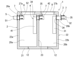
この実施例の油水分離槽1は、複数(具体的には、2つまたは3つ、言い換えれば、複数かつ3以下)の分離室を備える油水分離槽1を2つ連接して構成される油水分離施設を形成するための油水分離槽である。油水分離槽1は、上流側分離室20aと、下流側分離室20bと、上流側分離室20aの側壁22aに設けられた第1の側壁開口部26aと、油水分離槽1内を複数の室に区分する仕切壁23に設けられた仕切壁開口部26cと、下流側分離室20bの側壁22bに設けられた第2の側壁開口部26bと、仕切壁開口部26cに、液密に装着され、上流側分離室20aと下流側分離室20bとを連通する分離室間連通管4とを備え、分離室間連通管4は、仕切壁開口部26cより上流側分離室20aの底部側にて開口する第1の開口と、下流側分離室20bの上部側にて開口する第2の開口とを備える。
The oil-water separation tank and the oil-water separation device of the present invention will be described with reference to the examples shown in the drawings.
The oil-
First, the oil-
The oil-
油水分離槽1は、第2の側壁開口部26bに装着された分離槽連結管3を備える。分離槽連結管3は、第2の側壁開口部26bより下流側分離室20bの底部側にて開口する第1の開口と、第2の側壁開口部26bより突出し、接続される第2油水分離槽(接続用油水分離槽)1bが備える第1の側壁開口部26aより、第2油水分離槽1bの上流側分離室20aに進入可能な管状突出部32と、管状突出部32に設けられた第2の開口と、油水分離槽1の下流側分離室20bの内壁(第2の側壁開口部26bの周縁部の内壁)に液密状態にて接触可能な第1の当接部34と、管状突出部32上を移動可能に設けられ、接続される第2油水分離槽(接続用分離槽)1bの第1の側壁開口部26aの内壁および管状突出部32の外面に液密状態にて接触可能な第2の当接部35と、第2の当接部35の一方の面側に当接し、第2の当接部35の他方の面側を第2油水分離槽1bの第1の側壁開口部26aの周縁部の内壁に押圧し、押圧状態にて固定するための固定部材7を備える。そして、固定部材7および第2の当接部35は、管状突出部32に装脱可能(言い換えれば、着脱可能)となっている。
The oil-
この実施例の油水分離槽1は、図1ないし図4に示すように、2つの上部開口部28a、28bと、内部に、上部開口部28aと連通する上流側分離室20aと、上部開口部28bと連通する下流側分離室20bを有する槽本体2と、上部開口部28a,28bに載置された蓋8とを備える。この実施例では、槽本体2は、プレキャストコンクリート製の槽本体となっている。
槽本体2は、図2および図4に示すように、底板部21と、底板部21の環状周縁部より上方に延びる環状の側壁部22と、底板部21の上面より上方に延び、かつ両側部が、環状の側壁部22と連結した仕切壁23とを備える。この仕切壁23により、槽本体2内は、上流側分離室20aと、下流側分離室20bに区分され、複数の分離室を備えるものとなっている。また、環状の側壁部22は、矩形状に配置された4枚の側壁部により構成されており、上流側分離室20a側の側壁22aと、下流側分離室20bの側壁22bを備える。
As shown in FIGS. 1 to 4, the oil-
As shown in FIGS. 2 and 4, the
さらに、上流側分離室20aの側壁22aは、第1の側壁開口部26aを備え、仕切壁23は、仕切壁開口部26cを備え、下流側分離室20bの側壁22bは、第2の側壁開口部26bを備えている。また、この実施例では、槽本体2は、各分離室の底板部21に貫通孔12を備えている。貫通孔12は、槽本体の設置場所への固定時におけるボルト挿通部として使用できる。
Further, the
また、槽本体2の上部かつ上部開口部28a、28bの内側には、蓋載置部27a,27bが形成されている。蓋載置部27a,27bは、環状の側壁部22および仕切部23の上端部に形成されており、かつ、環状の側壁部22および仕切部23の上端部より、上部開口部28a、28bの内側に環状に突出するものとなっている。また、蓋載置部27a,27bの内面は、下方に向かって狭くなるもの、言い換えれば、上方に向かって広がるものとなっている。また、プレキャストコンクリート製の槽本体を構成する底板部、側壁部、仕切部には、補強用の鋼材が埋設されていることが好ましい。
蓋8は、槽本体2に装脱可能なものとなっている。蓋8としては、鋼製、特に、ダクタイル鋼製のものが好適である。また、蓋は、槽内視認用の開閉可能な窓部を備えるものであってもよい。
っている。
Further,
The
ing.
そして、この実施例の油水分離槽1は、図1ないし図4に示すように、第2の側壁開口部26bに装着された分離槽連結管3を備える。
本発明の分離槽連結管3は、隣り合う2つの油水分離槽を連結するためのものである。そして、この実施例の分離槽連結管3は、下方に延び、かつ下端部に第1の開口を有する管状本体31と、管状本体31の上部と連通し、かつ側部方向に延び、油水分離槽1の側壁開口部26bを貫通可能かつ、接続される第2油水分離槽が備える側壁開口部26aより、第2油水分離槽内に進入可能な管状突出部32と、管状突出部32に被装され、油水分離槽1の側壁開口部26bの内壁に液密状態にて接触可能な第1の当接部34と、管状突出部32上を移動可能に設けられ、接続される第2油水分離槽の側壁開口部26aの内壁および管状突出部32の外面に液密状態にて接触可能な第2の当接部35と、第2の当接部35の一方の面側に当接し、第2の当接部35の他方の面側を第2油水分離槽の側壁開口部26aの周縁部の内壁に押圧し、押圧状態にて固定するための固定部材7とを備える。そして、固定部材7および第2の当接部35は、管状突出部32に装脱可能(具体的には、着脱可能)となっている。
Then, as shown in FIGS. 1 to 4, the oil-
The separation
この実施例の油水分離槽1では、分離槽連結管3は、図11ないし図13に示すように、第2の側壁開口部26bより下流側分離室20bの底部側にて開口する第1の開口36と、第2の側壁開口部26bより突出し、接続される第2油水分離槽1b(もしくは第2油水分離槽1c)が備える第1の側壁開口部26aより、第2油水分離槽1bの上流側分離室20aに進入可能な管状突出部32と、管状突出部32に設けられた第2の開口37とを備える。
In the oil-
具体的には、分離槽連結管3は、第2の側壁開口部26bより下流側分離室20bの底部方向に延びる管状本体31を備え、第1の開口36は、管状本体31の下端部に設けられている。また、分離槽連結管3は、管状本体31の上端部に接続され、側部方向(直交方向)に延びる管状突出部32を備える。管状突出部32は、第2の側壁開口部26bを貫通し、さらに、図17に示すように、連接される第2油水分離槽1bの第1の側壁開口部26aを貫通し、上流側分離室20aに進入可能なものとなっている。そして、管状突出部32の先端部に第2の開口37が設けられている。この実施例では、分離槽連結管3の管状本体31と管状突出部32は、連通し、かつ、両者の中心軸は、ほぼ直交するものとなっている。
Specifically, the separation
また、分離槽連結管3は、図3、図11ないし図13、図17に示すように、油水分離槽1の下流側分離室20bの内壁に液密状態にて接触可能(当接可能)な第1の当接部34と、管状突出部32上を移動可能に設けられ、接続される第2油水分離槽1bの第1の側壁開口部26aの内壁および管状突出部32の外面に液密状態にて接触可能(当接可能)な第2の当接部35と、第2の当接部35を第2油水分離槽1bの第1の側壁開口部26aの周縁部の内壁に押圧状態にて固定するための固定部材7を備えている。そして、固定部材7は、第2の当接部35の一方の面側に当接し、第2の当接部35の他方の面側を第2油水分離槽1bの第1の側壁開口部26aの周縁部の内壁に押圧し、押圧状態にて固定するための機能を備えている。また、固定部材7および第2の当接部35は、管状突出部32に装脱可能(言い換えれば、着脱可能)となっている。
Further, as shown in FIGS. 3, 11, 13 and 17, the separation
この実施例では、第2の当接部35は、固定部材7と当接する一方の面側を有する当接板35aと、当接板35aの他方の面側に配置された環状シール部材35bを備えている。当接板としては、金属板(具体的には、鋼製)により形成されたドーナツ板状のものが好適である。この実施例では、管状突出部32は、金属製の円筒体により形成されており、当接板35aは、管状突出部32の外径より若干大きい内径の開口を有している。また、環状シール部材35bも管状突出部32の外径より若干大きい内径の開口を有している。環状シール部材35bとしては、押圧されることにより、開口部の内径が縮径し、管状突出部32の外面との間に液密状態を形成可能な弾性シール部材が好適である。弾性シール部材の形成材料としては、各種ゴム材、熱可塑性エラストマーなどの弾性材料が使用できる。環状シール部材35bは、当接板35aと第2油水分離槽1bの第1の側壁開口部26aの内壁間により挟圧され、管状突出部32の外面と第2の当接部35(具体的には、当接板35a)と上記の第2油水分離槽1bの側壁開口部26aの内壁間に液密状態を形成する。
In this embodiment, the
また、この実施例では、第1の当接部34も上述の第2の当接部35と同様に、当接板34aと、当接板34aの他方の面側に配置された環状シール部材34bを備えている。当接板34aは、分離槽連結管3の管状突出部32の基部もしくは基部付近に固定されている。当接板としては、金属板(具体的には、鋼製)により形成されたドーナツ板状のものが好適である。当接板34aは、管状突出部32の外径より若干大きい内径の開口を有し、装着された後、固定されている。特に、この実施例では、当接板34aは、分離槽連結管3の管状突出部32の基部に液密状態にて溶接固定されている。
また、環状シール部材34bは、当接板34aと第2の側壁開口部26bの内壁間により挟圧され、液密状態を形成する。なお、環状シール部材34bは、押圧されることにより、管状突出部32の外面に液密状態にて接触するものであってもよい。この実施例では、環状シール部材34bも管状突出部32の外径より若干大きい内径の開口を有している。環状シール部材34bとしては、押圧されることにより、開口部の内径が縮径し、管状突出部32の外面との間に液密状態を形成可能な弾性シール部材が好適である。弾性シール部材の形成材料としては、各種ゴム材、熱可塑性エラストマーなどの弾性材料が使用できる。
Further, in this embodiment, the
Further, the
そして、この実施例では、図11ないし図16に示すように、分離槽連結管3は、管状突出部32に設けられた固定部材7を装着するための装着用貫通孔39を備えている。この実施例では、装着用貫通孔39は、分離槽連結管3の中心軸に対して、ほぼ等角度に2つ以上、具体的には、3つ設けられており、かつ、各装着用貫通孔39に固定部材7が取り外し可能に装着されている。
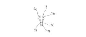
固定部材7は、図14ないし図16に示すように、固定部材本体71と、固定部材本体71の側面より外方に延び、かつ、装着用貫通孔39に挿入可能かつ係合可能な挿入係合部74を備える装着部73と、固定部材本体71と螺合し、螺合の進行により、第2の当接部方向に移動可能な押圧部72とを備えている。
Then, in this embodiment, as shown in FIGS. 11 to 16, the separation
As shown in FIGS. 14 to 16, the fixing
固定部材本体71は、所定長延びる筒状部材であり、内部に貫通路を備え、貫通路の内面には、雌ねじ部を備えている。押圧部72は、外面に、固定部材本体71の雌ねじ部と螺合可能な雄ねじ部を有するシャフト部72aと、回転操作用ヘッド部72bを備えている。回転操作用ヘッド部72bを回転させ、螺合の進行および後退により、シャフト部72aは、固定部材本体71に対して、前後方向に移動する。シャフト部72aの先端は、第2の当接部35(具体的には、当接板35a)に当接可能であり、かつ押圧可能なものとなっている。
The fixing member
固定部材7の装着部73は、装着用貫通孔39への挿入係合部74と挿入係合部74の上部に形成された切欠部75を備えている。挿入係合部74は、装着用貫通孔39の軸方向長より短いものとなっており、装着用貫通孔39に挿入可能となっている。切欠部75は、管状突出部32の肉厚とほぼ同じもしくは若干大きい幅を持っており、切欠部75内に、装着用貫通孔39の第2の開口37側の端部が、進入可能なものとなっている。切欠部75が、装着用貫通孔39の第2の開口37側の端部を収納した状態とすることにより、固定部材7を管状突出部32の装着用貫通孔39に装着でき、装着された固定部材7は、管状突出部32からの離脱と第2の開口37方向への移動が規制される。
The mounting
そして、この実施例の油水分離槽1は、図1ないし図4に示すように、仕切壁開口部26cに液密に装着された分離室間連通管4を備えている。分離室間連通管4は、仕切壁開口部26cより上流側分離室20aの底部側にて開口する第1の開口と、下流側分離室20bの上部側にて開口する第2の開口とを備える。具体的には、分離室間連通管4は、仕切壁開口部26cより上流側分離室20aの底部方向に延びる管状本体41を備え、第1の開口は、管状本体41の下端部に設けられている。
Then, as shown in FIGS. 1 to 4, the oil-
また、分離室間連通管4は、管状本体41の上端部に接続された管状突出部42を備え、管状突出部42は、仕切壁開口部26cを貫通し、下流側分離室20bに進入している。そして、管状突出部42の先端部に第2の開口が設けられている。この実施例では、分離室間連通管4の管状本体41と管状突出部42は、連通し、かつ、両者の中心軸は、ほぼ直交するものとなっている。また、分離室間連通管4は、仕切壁開口部26cが形成された仕切壁23の両面において、液密状態にて仕切壁23に固定されている。特に、この実施例では、上述した分離槽連結管3が備えるものと同様の第1の当接部34,第2の当接部35および固定手段7を備えている。
Further, the
図3に示すように、第1の当接部34は、油水分離槽1の上流側分離室20aの仕切壁開口部26cの内壁および管状突出部42の外面に液密状態にて固定されており、第2の当接部35は、油水分離槽1の下流側分離室20bの仕切壁開口部26cの内壁および管状突出部42の外面に液密状態にて固定されている。このため、上流側分離室20aと下流側分離室20bは、分離室間連通管4の内部管路を通じてのみ、連通している。
As shown in FIG. 3, the
さらに、この実施例の油水分離槽1は、図1ないし図4に示すように、上流側分離室20aの側壁22aに設けられた第1の側壁開口部26aに液密に装着された流入管5を備えている。流入管5は、第1の側壁開口部26aの外側にて開口する流入口と、上流側分離室20aの上部側にて開口する流出口とを備え、円筒状のものとなっている。
Further, as shown in FIGS. 1 to 4, the oil-
具体的には、流入管5は、第1の側壁開口部26aの外方に延びる排水路接続部51と、上流側分離室20a内に突出する管状突出部52を備え、管状突出部52は、第1の側壁開口部26aを貫通し、先端部に流出口が設けられている。また、流入管5は、第1の側壁開口部26aが形成された側壁22aの両面において、液密状態にて側壁22aに固定されている。特に、この実施例では、上述した分離槽連結管3が備えるものと同様の第1の当接部34,第2の当接部35および固定手段7を備えている。
Specifically, the
また、本発明の油水分離槽としては、図5に示す油水分離槽1aのように、3つの分離室を備えるものであってもよい。この実施例の油水分離槽1aでは、上流側分離室20aと下流側分離室20b間に、中間分離室20cを備えている。
上述した油水分離槽1とこの油水分離槽1aとの相違は、中間分離室20cの有無のみである。この実施例の油水分離槽1aに用いられている槽本体2aは、図5に示すように、2つの仕切壁23a、23bを備えており、それぞれの仕切壁に仕切壁開口部が形成されている。さらに、各仕切壁開口部に、分離室間連通管4が液密状態にて装着されている。分離室間連通管4としては、上述したものが好適に使用される。
Further, the oil-water separation tank of the present invention may be provided with three separation chambers as in the oil-
The only difference between the oil-
また、本発明の油水分離装置10に使用される第2油水分離槽(接続用油水分離槽)としては、図6に示す油水分離槽1bが使用される。
この油水分離槽1bの基本構成は、上述した油水分離槽1と同じであり、相違点は、流入管5を備えない点と、分離槽連結管3の代わりに、排出管6が装着されている点のみである。この油水分離槽1bでは、油水分離槽1の分離槽連結管3の管状突出部32を挿入可能とするため、上流側分離室20aの側壁22aに設けられた第1の側壁開口部26aは、開放状態となっている。
Further, as the second oil-water separation tank (connecting oil-water separation tank) used in the oil-
The basic configuration of the oil-
そして、図6に示すように、下流側分離室20bの側壁23bに形成された第2の側壁開口部26bに液密に装着された排出管6を備えている。排出管6は、第2の側壁開口部26bより下流側分離室20bの底部側にて開口する第1の開口と、第2の側壁開口部26bの外側にて開口する第2の開口とを備える。具体的には、排出管6は、第2の側壁開口部26bより下流側分離室20bの底部方向に延びる管状本体61を備え、第1の開口は、管状本体61の下端部に設けられている。
Then, as shown in FIG. 6, the
また、排出管6は、管状本体61の上端部に接続された管状突出部62を備え、管状突出部62は、第2の側壁開口部26bを貫通し、外部に突出し、排水路接続部を形成している。この実施例では、排出管6の管状本体61と管状突出部62は、連通し、かつ、両者の中心軸は、ほぼ直交するものとなっている。また、排出管6は、第2の側壁開口部26bが形成された側壁22bの両面において、液密状態にて側壁22bに固定されている。特に、この実施例では、排出管6は、上述した分離槽連結管3が備えるものと同様の第1の当接部34,第2の当接部35および固定手段7を備えている。
Further, the
また、本発明の油水分離装置10に使用される第2油水分離槽としては、図7に示すような油水分離槽1cを使用してもよい。
この油水分離槽1cの基本構成は、上述した油水分離槽1bと同じであり、相違点は、この実施例の油水分離槽1cでは、上流側分離室20aと下流側分離室20b間に、中間分離室20cを備える点のみである。この実施例の油水分離槽1cに用いられている槽本体2aは、図7に示すように、2つの仕切壁23a、23bを備えており、それぞれの仕切壁に仕切壁開口部が形成されている。さらに、各仕切壁開口部に、分離室間連通管4が液密状態にて装着されている。分離室間連通管4としては、上述したものが好適に使用される。
Further, as the second oil-water separation tank used in the oil-
The basic configuration of the oil-water separation tank 1c is the same as that of the oil-
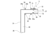
また、本発明の油水分離槽としては、図8に示す油水分離槽1dのように、1つのみの分離槽を備えるものであってもよい。
この実施例の油水分離槽1dは、図8に示すように、1つの分離室20と、流入側の側壁24に設けられた第1の側壁開口部26aと、流出側の側壁25に設けられた第2の側壁開口部26bと、第2の側壁開口部26bに装着された分離槽連結管3とを備える。分離槽連結管3は、第2の側壁開口部26b(具体的には、第2の側壁開口部の内側)より分離室20の底部側に延びかつ下部に第1の開口を有する管状本体31と、第2の側壁開口部26bより突出し、接続される第2油水分離槽1eが備える第1の側壁開口部26aより、第2油水分離槽1eの分離室20に進入可能な管状突出部32と、管状突出部32に設けられた第2の開口と、油水分離槽1dの分離室20の内壁に液密状態にて接触可能な第1の当接部34と、管状突出部32上を移動可能に設けられ、接続される第2油水分離槽1eの第1の側壁開口部26aの内壁および管状突出部32の外面に液密状態にて接触可能な第2の当接部35と、第2の当接部35の一方の面側に当接し、第2の当接部35の他方の面側を第2油水分離槽1eの第1の側壁開口部26aの周縁部の内壁に押圧し、押圧状態にて固定するための固定部材7を備える。固定部材7および第2の当接部34は、管状突出部32に装脱可能(言い換えれば、着脱可能)となっている。
Further, the oil-water separation tank of the present invention may be provided with only one separation tank, such as the oil-
As shown in FIG. 8, the oil-
この実施例の油水分離槽1dは、槽本体2bと、分離槽連結管3と、流入管5と、蓋8とを備える。
槽本体2bは、底板部21と、底板部21の環状周縁部より上方に延びる環状の側壁部22とを備える。また、環状の側壁部22は、矩形状に配置された4枚の側壁部により構成されており、流入側の側壁24に第1の側壁開口部26aを備え、流出側の側壁25に第2の側壁開口部26bを備えている。この実施例では、槽本体2bは、プレキャストコンクリート製の槽本体となっている。また、この実施例では、槽本体2bは、分離室20の底板部21に貫通孔12を備えている。貫通孔12は、槽本体を施設へ固定時におけるボルト挿通部として使用できる。
The oil-
The
また、槽本体2bの上部かつ上部開口部28の内側には、蓋載置部27が形成されている。蓋載置部27は、環状の側壁部22の上端部に形成されており、かつ、環状の側壁部22の上端部より、上部開口部28の内側に環状に突出するものとなっている。また、蓋載置部27の内面は、下方に向かって狭くなるもの、言い換えれば、上方に向かって広がるものとなっている。また、プレキャストコンクリート製の槽本体を構成する底板部、側壁部、仕切部には、補強用の鋼材が埋設されていることが好ましい。上部開口部28には、蓋8が載置されている。蓋8は、槽本体2bに装脱可能なものとなっている。蓋8としては、鋼製、特に、ダクタイル鋼製のものが好適である。また、蓋8は、槽内視認用の開閉可能な窓部を備えるものであってもよい。
Further, a
分離槽連結管3は、流出側の側壁25の第2の側壁開口部26bに装着されている。分離槽連結管3としては、上述したものが使用される。分離槽連結管3の管状本体31は、第2の側壁開口部26b、具体的には、第2の側壁開口部の内側、より分離室20の底部側に延びかつ下部(具体的には、下端)に第1の開口を有する。管状突出部32は、管状本体31の上端部より側部外方に延び、第2の側壁開口部26bより突出し、接続される第2油水分離槽1eが備える第1の側壁開口部26aより、第2油水分離槽1eの分離室20に進入可能なものとなっている。流入管5は、槽本体2bの流入側の側壁24の第1の側壁開口部26aに装着されている。流入管5としては、上述したものが使用される。
The separation
次に、図17に示す本発明の油水分離装置10について説明する。
本発明の油水分離装置10は、上述したいずれかの油水分離槽を第1油水分離槽とし、第1油水分離槽と連結される第2油水分離槽とを備える油水分離装置である。第2油水分離槽は、少なくとも1つの分離室と、流入側の側壁に設けられた第1の側壁開口部26aと、流出側の側壁に設けられた第2の側壁開口部26bとを備える。第1油水分離槽の分離槽連結管3の管状突出部32は、連結される第2油水分離槽の第1の側壁開口部26aより、分離室内に進入可能であり、固定部材7は、第2の当接部35の一方の面側に当接し、第2の当接部35の他方の面側を第1の側壁開口部26aの内壁を押圧し、固定部材7の押圧により、第2の当接部35は、第2油水分離槽の第1の側壁開口部26aの内壁および管状突出部32の外面に液密状態にて接触可能(当接可能)であり、かつ、固定部材7により、当該液密状態が維持可能なものとなっている。
Next, the oil-
The oil-
この実施例では、油水分離槽として、上述した第1油水分離槽1が使用され、第2油水分離槽として、上述した油水分離槽1bが使用されている。第2油水分離槽1bは、上流側分離室20aの側壁22aが、第1油水分離槽1の下流側分離室の側壁22bと向かい合うように配置され、さらに、第1油水分離槽1と第2油水分離槽1bは、第1油水分離槽1が備える分離槽連結管3により連通しかつ連結されている。この実施例の油水分離装置10は、直列的に配置された4つの分離室を備えている。
In this embodiment, the above-mentioned first oil-
第1油水分離槽1と第2油水分離槽1bの連結(連接)は、下記のようにして行うことができる。
分離槽連結管3の固定部材7および第2の当接部35は、管状突出部32に装脱可能(言い換えれば、着脱可能)となっている。固定部材7および第2の当接部35を取り外した状態にて、管状突出部32を第2油水分離槽1bの第1の側壁開口部26aより、第2油水分離槽1bの上流側分離室20aに進入させた後、分離槽連結管3の管状突出部32に第2の当接部35を被装し、装着用貫通孔39を通過させ、続いて、各装着用貫通孔39に固定部材7を装着する。
The connection (connection) between the first oil-
The fixing
そして、各固定部材7の押圧部72を回転させることにより、押圧部72の先端部を第2の当接部35に当接させる。さらに、各固定部材7の押圧部72を回転させることにより、押圧部72に押されて、第2の当接部35は、第1の当接部34方向に移動し、第2油水分離槽1bの第1の側壁開口部26aの内壁に、環状シール部材が当接し、図14に示すように、第2の当接部35は、第2油水分離槽1bの第1の側壁開口部26aの内壁および管状突出部32の外面に液密状態にて固定される。このとき、同時に、第1の当接部34の環状シール部材も油水分離槽1の第2の側壁開口部26bの内壁に当接し、第1の当接部34は、油水分離槽1の第2の側壁開口部26bの内壁および管状突出部32の外面に液密状態にて固定される。
Then, by rotating the
また、この状態において、各固定部材は、第2の当接部35方向への移動が規制され、分離槽連結管3より離脱不能となる。これにより、第1油水分離槽1と第2油水分離槽1bは、分離槽連結管3により連結されかつ液密状態にて連通する。具体的には、第1油水分離槽1の下流側分離室20bと第2油水分離槽1bの上流側分離室20aは、分離槽連結管3の内部管路30を介してのみ連通し、それぞれの分離室は、外部と連通しないものとなっている。
Further, in this state, the movement of each fixing member in the direction of the
また、図18に示す本発明の油水分離装置10aのように、第1油水分離槽として、上述した第1油水分離槽1aを使用し、第2油水分離槽として、上述した油水分離槽1bを使用したものであってもよい。第2油水分離槽1bは、上流側分離室20aの側壁22aが、第1油水分離槽1aの下流側分離室の側壁22bと向かい合うように配置され、さらに、第1油水分離槽1aと第2油水分離槽1bは、第1油水分離槽1aが備える分離槽連結管3により連通しかつ連結されている。この実施例の油水分離装置10aは、直列的に配置された5つの分離室を備えている。
Further, as in the oil-
さらに、本発明の油水分離装置としては、第1油水分離槽として、上述した第1油水分離槽1aを使用し、第2油水分離槽として、上述した油水分離槽1cを使用したものであってもよい。第2油水分離槽1cは、上流側分離室20aの側壁22aが、第1油水分離槽1aの下流側分離室の側壁22bと向かい合うように配置され、さらに、第1油水分離槽1aと第2油水分離槽1cは、第1油水分離槽1aが備える分離槽連結管3により連通しかつ連結される。この実施例の油水分離装置は、直列的に配置された6つの分離室を備えるものとなる。
Further, as the oil-water separation device of the present invention, the above-mentioned first oil-
次に、図19に示す本発明の油水分離装置10bについて説明する。
この実施例では、第1油水分離槽として、上述した油水分離槽1dが使用され、第2油水分離槽および第3油水分離槽として、後述する油水分離槽1e(中間接続用の油水分離槽)が使用され、そして、第4油水分離槽として、後述する油水分離槽1f(末端接続用の油水分離槽)が使用され、隣り合う油水分離槽が、分離槽連結管3により連結されている。この実施例の油水分離装置10bは、直列的に配置された4つの分離室を備えるものとなっている。
Next, the oil-water separation device 10b of the present invention shown in FIG. 19 will be described.
In this embodiment, the above-mentioned oil-
中間接続用の油水分離槽1eは、図9に示すように、流入管5を備えない以外は、上述した油水分離槽1dと同じ構成を備えるものとなっている。流入管5は、上述したものと同じである。また、末端接続用の油水分離槽1fは、図10に示すように、流入管5を備えず、さらに、分離槽連結管3の代わりに排出管6を備えていること以外は、上述した油水分離槽1dと同じ構成を備えるものとなっている。また、排出管6は、上述したものと同じである。
As shown in FIG. 9, the oil-
そして、図19に示すように、第1油水分離槽である油水分離槽1dの分離槽連結管3の管状突出部は、隣り合う第2の油水分離槽1eの流入側の側壁24に設けられた第1の側壁開口部26aを貫通し、油水分離槽1eの分離室20内に位置している。さらに、図19に示すように、第2の当接部35は、第2油水分離槽1eの第1の側壁開口部26aの内壁および管状突出部外面に液密状態にて固定され、第1の当接部34の環状シール部材も第1油水分離槽1dの第2の側壁開口部26bの内壁に当接し、第1の当接部34は、第1油水分離槽1dの第2の側壁開口部26bの内壁および管状突出部の外面に液密状態にて固定され、かつ、固定部材7により、その状態が保持されている。これにより、隣り合う油水分離槽1e,1fは、分離槽連結管3により、液密状態にて連通しかつ連結される。隣り合う油水分離槽間の連結(連接)は、上述した方法にて行うことができる。
Then, as shown in FIG. 19, the tubular protrusion of the separation
同様に、図19に示すように、第2油水分離槽である油水分離槽1eの分離槽連結管3の管状突出部は、隣り合う第3の油水分離槽1eの流入側の側壁24に設けられた第1の側壁開口部26aを貫通し、油水分離槽1eの分離室20内に位置している。そして、隣り合う油水分離槽1e,1eは、分離槽連結管3により、液密状態にて連通しかつ連結されている。
Similarly, as shown in FIG. 19, the tubular protrusion of the separation
さらに、第1の当接部34,第2の当接部35および固定部材7により、隣り合う油水分離槽1e,1eは、液密状態にて連通しかつ連結されている。同様に、図19に示すように、第3油水分離槽である油水分離槽1eの分離槽連結管3の管状突出部は、隣り合う第4の油水分離槽1f(この実施例では、末端接続用の油水分離槽)の流入側の側壁24に設けられた第1の側壁開口部26aを貫通し、油水分離槽1fの分離室20内に位置している。そして、隣り合う油水分離槽1e,1fは、分離槽連結管3により、液密状態にて連通しかつ連結されている。
Further, the adjacent oil-
また、上述したすべての実施例の油水分離槽および油水分離装置に使用される分離槽連結管としては、図20および図21に示すようなタイプの固定部材(固定機構)を備える分離槽連結管3aであってもよい。また、分離室間連通管、流入管、排出管としても、同様に、図20および図21に示すようなタイプの固定部材(固定機構)を備えるものであってもよい。 Further, as the separation tank connecting pipe used for the oil-water separation tank and the oil-water separation device of all the above-mentioned examples, the separation tank connecting pipe provided with the type of fixing member (fixing mechanism) as shown in FIGS. 20 and 21. It may be 3a. Further, the communication pipe between the separation chambers, the inflow pipe, and the discharge pipe may also be provided with a fixing member (fixing mechanism) of the type shown in FIGS. 20 and 21.
図20は、本発明の油水分離槽および油水分離装置に使用される分離槽連結管および固定部材の他の例の正面図である。この分離槽連結管3aと上述した分離槽連結管3との相違点は、第2の当接部35の固定機構のみであり、管状本体31、第1の当接部34、第2の当接部35は、上述したものと同じである。
この分離槽連結管3aでは、管状突出部32aを備え、その先端部に第2の開口が設けられている。分離槽連結管3aの管状本体31と管状突出部32aは、連通し、かつ、両者の中心軸は、ほぼ直交するものとなっている。この分離槽連結管3aは、管状突出部32aの外面に設けられた雄側螺合部と、前記雄側螺合部と螺合可能な雌側螺合部を有する固定部材9を備える。固定部材9の螺合の進行により、固定部材9は、第2の当接部35方向に移動可能であり、かつ先端面が、第2の当接部35に当接可能かつ押圧可能となっている。固定部材9は、管状突出部32aより、離脱可能である。
FIG. 20 is a front view of another example of the separation tank connecting pipe and fixing member used in the oil-water separation tank and the oil-water separation device of the present invention. The difference between the separation
The separation
管状突出部32aは、図20および図21に示すように、先端部82が小径部となっており、基端部81(管状本体31側部分)が、大径部となっている。そして、管状突出部32aの外面、具体的には、大径となっている基端部82の先端部に雄側螺合部83(具体的には、雄ねじ)を備えている。そして、管状突出部32aには、固定部材9が被装されている。
固定部材9は、図20および図21に示すように、円筒状の固定部材本体91と、固定部材本体91の側面より外方に突出する操作用把持部94を備えている。固定部材本体91の内面には、管状突出部32aに設けられた雄側螺合部83(具体的には、雄ねじ)と螺合可能な、雌側螺合部93(具体的には、雌ねじ)が形成されている。
As shown in FIGS. 20 and 21, the
As shown in FIGS. 20 and 21, the fixing
また、円筒状の固定部材本体91の先端部内面には、螺合部を備えない内径拡径部95が設けられている。内径拡径部95は、大径の基端部82の螺合部のない部分を移動可能となっている。内径拡径部95の先端面は、第2の当接部35に当接可能であり、かつ押圧可能となっている。固定部材9を回転させて、螺合を進行させると、固定部材9は、第2の当接部35に近接し、その先端が当接する。さらに、螺合を進行させると、第2の当接部35は、固定部材9により押圧され、装着対象の壁部に液密状態にて当接し、その状態が保持される。
Further, an inner diameter enlarged
1,1a 油水分離槽
10,10a 油水分離装置
2 槽本体
3 分離槽連結管
4 分離室間連通管
5 流入管
6 排出管
7 固定部材
20a 上流側分離室
20b 下流側分離室
34 第1の当接部
35 第2の当接部
1,1a Oil-
Claims (10)
前記油水分離槽は、少なくとも1つの分離室と、前記分離室の流入側の側壁に設けられた第1の側壁開口部と、前記分離室の流出側の側壁に設けられた第2の側壁開口部と、前記第2の側壁開口部に装着された分離槽連結管とを備え、
前記分離槽連結管は、前記第2の側壁開口部より前記分離室の底部側に延び、下部に第1の開口を有する管状本体と、前記管状本体と連通し、前記第2の側壁開口部より突出し、接続される前記接続用油水分離槽が備える側壁開口部より、前記接続用油水分離槽の分離室に進入可能な管状突出部と、前記油水分離槽の分離室の内壁に液密状態にて当接可能な第1の当接部と、前記管状突出部上を移動可能に設けられ、接続される前記接続用油水分離槽の前記側壁開口部の周縁部の内壁および前記管状突出部の外面に液密状態にて接触可能な第2の当接部と、前記第2の当接部の一方の面側に当接し、前記第2の当接部の他方の面側を前記接続用油水分離槽の前記側壁開口部の周縁部の内壁に押圧し、押圧状態にて固定するための固定部材を備え、さらに、前記固定部材および前記第2の当接部は、前記管状突出部に装脱可能となっていることを特徴とする油水分離装置に使用される油水分離槽。 An oil-water separation tank used in an oil-water separation device that is configured by connecting an oil-water separation tank and a connection oil-water separation tank.
The oil-water separation tank has at least one separation chamber, a first side wall opening provided on the side wall on the inflow side of the separation chamber, and a second side wall opening provided on the side wall on the outflow side of the separation chamber. A section and a separation tank connecting pipe mounted on the second side wall opening are provided.
The separation tank connecting pipe extends from the second side wall opening toward the bottom of the separation chamber, communicates with a tubular body having a first opening at the bottom, and communicates with the tubular body, and the second side wall opening. A tubular protrusion that can enter the separation chamber of the connection oil-water separation tank from the side wall opening of the connection oil-water separation tank that is more protruding and connected, and a liquid-tight state on the inner wall of the separation chamber of the oil-water separation tank. The inner wall and the tubular protrusion of the peripheral edge of the side wall opening of the connecting oil-water separation tank that is movably provided and connected on the tubular protrusion and the first contact portion that can be contacted with the first contact portion. A second contact portion that can be contacted with the outer surface of the second contact portion in a liquidtight state and one surface side of the second contact portion are contacted, and the other surface side of the second contact portion is connected . A fixing member for pressing against the inner wall of the peripheral edge of the side wall opening of the oil-water separation tank and fixing the oil-water separation tank in the pressed state is provided, and the fixing member and the second contact portion are further formed by the tubular projecting portion. An oil-water separation tank used in an oil-water separation device, which is characterized by being removable.
前記第2油水分離槽は、少なくとも1つの分離室と、前記側壁開口部として、前記分離室の流入側の側壁に設けられた第1の側壁開口部と、前記分離室の流出側の側壁に設けられた第2の側壁開口部とを備え、
前記第1油水分離槽の前記分離槽連結管の前記管状突出部は、連結される前記第2油水分離槽の前記第1の側壁開口部より、前記分離室に進入可能であり、前記固定部材は、前記第2の当接部の一方の面側に当接し、前記第2の当接部の他方の面側を前記第2油水分離槽の前記第1の側壁開口部の周縁部の内壁に押圧可能であり、前記固定部材の押圧により、前記第2の当接部は、前記第2油水分離槽の前記第1の側壁開口部の周縁部の内壁および前記管状突出部の外面に液密状態にて接触可能であり、かつ、前記固定部材により、当該液密状態が維持可能であることを特徴とする油水分離装置。 The oil-water separation tank according to any one of claims 1 to 8 is provided as a first oil-water separation tank, and further, a second oil-water separation tank is provided as the connection oil-water separation tank connected to the first oil-water separation tank. It is an oil-water separator,
The second oil-water separation tank has at least one separation chamber, a first side wall opening provided on the side wall on the inflow side of the separation chamber, and a side wall on the outflow side of the separation chamber as the side wall opening. With a second side wall opening provided
The tubular protrusion of the separation tank connecting pipe of the first oil / water separation tank can enter the separation chamber from the first side wall opening of the second oil / water separation tank to be connected, and the fixing member. Abuts on one surface side of the second contact portion, and the other surface side of the second contact portion is the inner wall of the peripheral edge portion of the first side wall opening of the second oil / water separation tank. By pressing the fixing member, the second contact portion is brought into the inner wall of the peripheral edge of the first side wall opening of the second oil-water separation tank and the outer surface of the tubular protrusion. An oil-water separation device that can be contacted in a tight state and that the liquid-tight state can be maintained by the fixing member.
前記分離槽連結管は、下方に延び、かつ下端部に第1の開口を有する管状本体と、前記管状本体の上部と連通し、かつ側部方向に延び、前記第1油水分離槽の側壁開口部を貫通可能かつ、接続される前記第2油水分離槽が備える側壁開口部より、前記第2油水分離槽内に進入可能な管状突出部と、前記管状突出部に被装され、前記第1油水分離槽の側壁開口部の周縁部の内壁に当接可能な第1の当接部と、前記管状突出部上を移動可能に設けられ、接続される前記第2油水分離槽の側壁開口部の周縁部の内壁および前記管状突出部の外面に液密状態にて接触可能な第2の当接部と、前記第2の当接部の一方の面側に当接し、前記第2の当接部の他方の面側を前記第2油水分離槽の側壁開口部の周縁部の内壁に押圧し、押圧状態にて固定するための固定部材とを備え、さらに、前記固定部材および前記第2の当接部は、前記管状突出部に装脱可能となっていることを特徴とする分離槽連結管。 A separation tank connecting pipe for connecting the first oil-water separation tank and the second oil-water separation tank.
The separation tank connecting pipe communicates with a tubular main body having a first opening at the lower end and extending downward, and extends toward the side of the tubular main body, and has a side wall opening of the first oil-water separation tank. The first oil-water separation tank is covered with a tubular protrusion and a tubular protrusion that can enter the second oil-water separation tank through a side wall opening provided in the second oil-water separation tank that can penetrate and be connected to the portion. A first contact portion that can abut on the inner wall of the peripheral edge of the side wall opening of the oil-water separation tank, and a side wall opening of the second oil-water separation tank that is movably provided and connected on the tubular protrusion. A second contact portion that can be in contact with the inner wall of the peripheral portion of the peripheral portion and the outer surface of the tubular protrusion in a liquid-tight state, and one surface side of the second contact portion are contacted with the second contact portion. A fixing member for pressing the other surface side of the contact portion against the inner wall of the peripheral edge portion of the side wall opening of the second oil-water separation tank and fixing the contact portion in the pressed state is provided, and further, the fixing member and the second. The contact portion of the separation tank connecting pipe is characterized in that it can be attached to and detached from the tubular protruding portion.
Priority Applications (1)
| Application Number | Priority Date | Filing Date | Title |
|---|---|---|---|
| JP2017157197A JP7008949B2 (en) | 2017-08-16 | 2017-08-16 | Oil-water separation tank, oil-water separation device and separation tank connecting pipe |
Applications Claiming Priority (1)
| Application Number | Priority Date | Filing Date | Title |
|---|---|---|---|
| JP2017157197A JP7008949B2 (en) | 2017-08-16 | 2017-08-16 | Oil-water separation tank, oil-water separation device and separation tank connecting pipe |
Publications (3)
| Publication Number | Publication Date |
|---|---|
| JP2019034278A JP2019034278A (en) | 2019-03-07 |
| JP2019034278A5 JP2019034278A5 (en) | 2020-07-30 |
| JP7008949B2 true JP7008949B2 (en) | 2022-01-25 |
Family
ID=65636509
Family Applications (1)
| Application Number | Title | Priority Date | Filing Date |
|---|---|---|---|
| JP2017157197A Active JP7008949B2 (en) | 2017-08-16 | 2017-08-16 | Oil-water separation tank, oil-water separation device and separation tank connecting pipe |
Country Status (1)
| Country | Link |
|---|---|
| JP (1) | JP7008949B2 (en) |
Families Citing this family (3)
| Publication number | Priority date | Publication date | Assignee | Title |
|---|---|---|---|---|
| JP7389462B2 (en) | 2019-11-05 | 2023-11-30 | 株式会社赤羽コンクリート | oil water separation tank |
| CN111393320B (en) * | 2020-03-24 | 2023-05-16 | 浙江汇翔新材料科技股份有限公司 | N-cyanoethyl-N-benzyl aniline synthesis processing device |
| CN114307255A (en) * | 2021-12-08 | 2022-04-12 | 中核内蒙古矿业有限公司 | Continuous working oil-water separation device |
Citations (3)
| Publication number | Priority date | Publication date | Assignee | Title |
|---|---|---|---|---|
| JP2004314000A (en) | 2003-04-18 | 2004-11-11 | Ooike Co Ltd | Oil-water separator |
| CN104399285A (en) | 2014-11-03 | 2015-03-11 | 河南晋开化工投资控股集团有限责任公司 | Oil-water separation device |
| JP3208560U (en) | 2016-11-08 | 2017-01-26 | 株式会社北関東工業 | Dust trap |
Family Cites Families (2)
| Publication number | Priority date | Publication date | Assignee | Title |
|---|---|---|---|---|
| JPS61121904U (en) * | 1985-01-14 | 1986-08-01 | ||
| JPH0632161Y2 (en) * | 1987-03-09 | 1994-08-24 | 日建工業株式会社 | Precast oil / water separation tank for gas stations |
-
2017
- 2017-08-16 JP JP2017157197A patent/JP7008949B2/en active Active
Patent Citations (3)
| Publication number | Priority date | Publication date | Assignee | Title |
|---|---|---|---|---|
| JP2004314000A (en) | 2003-04-18 | 2004-11-11 | Ooike Co Ltd | Oil-water separator |
| CN104399285A (en) | 2014-11-03 | 2015-03-11 | 河南晋开化工投资控股集团有限责任公司 | Oil-water separation device |
| JP3208560U (en) | 2016-11-08 | 2017-01-26 | 株式会社北関東工業 | Dust trap |
Also Published As
| Publication number | Publication date |
|---|---|
| JP2019034278A (en) | 2019-03-07 |
Similar Documents
| Publication | Publication Date | Title |
|---|---|---|
| JP7008949B2 (en) | Oil-water separation tank, oil-water separation device and separation tank connecting pipe | |
| US4253282A (en) | Preformed manhole base section construction | |
| JP2009058055A (en) | Check valve setting method and check valve unit | |
| KR101129379B1 (en) | A storage tank | |
| US1686310A (en) | Slush-pump manifold | |
| KR20050047028A (en) | Fabricated precast concrete sewerage manhole | |
| JP7058527B2 (en) | Fittings and sewage drainage system | |
| JP2011106572A (en) | Branch pipe connector | |
| KR101826619B1 (en) | Non-buoyant sump haning function of preventing leak | |
| US10981815B1 (en) | One piece watertight concrete structure | |
| KR101428586B1 (en) | Sludge hopper preventing leakage of remaining liquid | |
| KR200342335Y1 (en) | Fabricated Precast Concrete Sewerage Manhole | |
| KR101726275B1 (en) | manhole | |
| JP2020204346A (en) | Piping member | |
| CN203868366U (en) | Electric zero-clearance gate valve | |
| WO2006073612A1 (en) | Apparatus and method for placement of a water closet fitting | |
| KR101325966B1 (en) | The piping fix sleeve of buliding with multi storey type structure | |
| KR101877886B1 (en) | Booster pump unit connecting method and booster pump apparatus | |
| KR101059542B1 (en) | manhole | |
| JPH0734873Y2 (en) | Connection structure of tanks | |
| KR100540220B1 (en) | A guide device that insert grand packing of watercontrol valve for pipe water works | |
| US20160084032A1 (en) | Well Casing Heads, Systems, and Methods for Removing Fluid from Earth about an Underground Platform | |
| KR101212712B1 (en) | a valve room | |
| KR100746715B1 (en) | Manhole System Using Parts of Pipe | |
| KR100756307B1 (en) | The connecting structure of sewage and wast water pipe |
Legal Events
| Date | Code | Title | Description |
|---|---|---|---|
| A521 | Written amendment |
Free format text: JAPANESE INTERMEDIATE CODE: A523 Effective date: 20200525 |
|
| A621 | Written request for application examination |
Free format text: JAPANESE INTERMEDIATE CODE: A621 Effective date: 20200525 |
|
| RD02 | Notification of acceptance of power of attorney |
Free format text: JAPANESE INTERMEDIATE CODE: A7422 Effective date: 20200525 |
|
| A977 | Report on retrieval |
Free format text: JAPANESE INTERMEDIATE CODE: A971007 Effective date: 20210527 |
|
| A131 | Notification of reasons for refusal |
Free format text: JAPANESE INTERMEDIATE CODE: A131 Effective date: 20210608 |
|
| A521 | Written amendment |
Free format text: JAPANESE INTERMEDIATE CODE: A523 Effective date: 20210730 |
|
| TRDD | Decision of grant or rejection written | ||
| A01 | Written decision to grant a patent or to grant a registration (utility model) |
Free format text: JAPANESE INTERMEDIATE CODE: A01 Effective date: 20211228 |
|
| A61 | First payment of annual fees (during grant procedure) |
Free format text: JAPANESE INTERMEDIATE CODE: A61 Effective date: 20211228 |
|
| R150 | Certificate of patent or registration of utility model |
Ref document number: 7008949 Country of ref document: JP Free format text: JAPANESE INTERMEDIATE CODE: R150 |