JP7007190B2 - Bone material remover and how to use it - Google Patents
Bone material remover and how to use it Download PDFInfo
- Publication number
- JP7007190B2 JP7007190B2 JP2017552067A JP2017552067A JP7007190B2 JP 7007190 B2 JP7007190 B2 JP 7007190B2 JP 2017552067 A JP2017552067 A JP 2017552067A JP 2017552067 A JP2017552067 A JP 2017552067A JP 7007190 B2 JP7007190 B2 JP 7007190B2
- Authority
- JP
- Japan
- Prior art keywords
- cannula
- bone
- cutting blade
- hole widening
- hole
- Prior art date
- Legal status (The legal status is an assumption and is not a legal conclusion. Google has not performed a legal analysis and makes no representation as to the accuracy of the status listed.)
- Active
Links
Images


Classifications
-
- A—HUMAN NECESSITIES
- A61—MEDICAL OR VETERINARY SCIENCE; HYGIENE
- A61B—DIAGNOSIS; SURGERY; IDENTIFICATION
- A61B17/00—Surgical instruments, devices or methods, e.g. tourniquets
- A61B17/16—Bone cutting, breaking or removal means other than saws, e.g. Osteoclasts; Drills or chisels for bones; Trepans
- A61B17/1662—Bone cutting, breaking or removal means other than saws, e.g. Osteoclasts; Drills or chisels for bones; Trepans for particular parts of the body
- A61B17/1675—Bone cutting, breaking or removal means other than saws, e.g. Osteoclasts; Drills or chisels for bones; Trepans for particular parts of the body for the knee
-
- A—HUMAN NECESSITIES
- A61—MEDICAL OR VETERINARY SCIENCE; HYGIENE
- A61B—DIAGNOSIS; SURGERY; IDENTIFICATION
- A61B17/00—Surgical instruments, devices or methods, e.g. tourniquets
- A61B17/16—Bone cutting, breaking or removal means other than saws, e.g. Osteoclasts; Drills or chisels for bones; Trepans
- A61B17/1613—Component parts
- A61B17/1615—Drill bits, i.e. rotating tools extending from a handpiece to contact the worked material
- A61B17/1617—Drill bits, i.e. rotating tools extending from a handpiece to contact the worked material with mobile or detachable parts
-
- A—HUMAN NECESSITIES
- A61—MEDICAL OR VETERINARY SCIENCE; HYGIENE
- A61B—DIAGNOSIS; SURGERY; IDENTIFICATION
- A61B17/00—Surgical instruments, devices or methods, e.g. tourniquets
- A61B17/16—Bone cutting, breaking or removal means other than saws, e.g. Osteoclasts; Drills or chisels for bones; Trepans
- A61B17/1613—Component parts
- A61B17/1631—Special drive shafts, e.g. flexible shafts
-
- A—HUMAN NECESSITIES
- A61—MEDICAL OR VETERINARY SCIENCE; HYGIENE
- A61B—DIAGNOSIS; SURGERY; IDENTIFICATION
- A61B17/00—Surgical instruments, devices or methods, e.g. tourniquets
- A61B17/16—Bone cutting, breaking or removal means other than saws, e.g. Osteoclasts; Drills or chisels for bones; Trepans
- A61B17/1635—Bone cutting, breaking or removal means other than saws, e.g. Osteoclasts; Drills or chisels for bones; Trepans for grafts, harvesting or transplants
-
- A—HUMAN NECESSITIES
- A61—MEDICAL OR VETERINARY SCIENCE; HYGIENE
- A61B—DIAGNOSIS; SURGERY; IDENTIFICATION
- A61B17/00—Surgical instruments, devices or methods, e.g. tourniquets
- A61B17/16—Bone cutting, breaking or removal means other than saws, e.g. Osteoclasts; Drills or chisels for bones; Trepans
- A61B17/1642—Bone cutting, breaking or removal means other than saws, e.g. Osteoclasts; Drills or chisels for bones; Trepans for producing a curved bore
-
- A—HUMAN NECESSITIES
- A61—MEDICAL OR VETERINARY SCIENCE; HYGIENE
- A61B—DIAGNOSIS; SURGERY; IDENTIFICATION
- A61B17/00—Surgical instruments, devices or methods, e.g. tourniquets
- A61B17/16—Bone cutting, breaking or removal means other than saws, e.g. Osteoclasts; Drills or chisels for bones; Trepans
- A61B17/1613—Component parts
- A61B17/1633—Sleeves, i.e. non-rotating parts surrounding the bit shaft, e.g. the sleeve forming a single unit with the bit shaft
Description
本発明は、そのいくつかの実施形態において、骨除去装置に関し、より詳細には、穴の有効径を変化させる装置に関するが、これに限らない。 The present invention relates to, but is not limited to, a bone removing device, more particularly a device that changes the effective diameter of a hole, in some embodiments thereof.
さまざまな整形外科再建手術、特に、たとえば前十字靭帯(ACL)再建等の靭帯または腱再建手術では、傷害組織を置き換えるために骨に挿入される手術用組織移植片(たとえば、靭帯移植片)の移植が必要である。傷害組織は、穿孔により形成された穴に移植片が挿通される前に骨から除去される。 In various orthopedic reconstructive surgeries, especially ligament or tendon reconstructive surgeries such as anterior cruciate ligament (ACL) reconstruction, of surgical tissue grafts (eg ligament grafts) that are inserted into the bone to replace the injured tissue. Needs transplantation. The injured tissue is removed from the bone before the graft is inserted into the hole formed by the perforation.
いくつかの靭帯または腱再建手術では、骨の表面深くにアンダーカットを穿孔して移植組織のアンカーを収容するのが有効である。 In some ligament or tendon reconstruction surgery, it is useful to perforate an undercut deep in the surface of the bone to accommodate the anchor of the transplanted tissue.
骨にアンダーカットを形成するいくつかの一般的な装置では、穿孔穴の壁の一部を周方向に擦って広げる単一の彫削刃を有する刃物を採用している。 Some common devices that form undercuts in bone employ blades with a single cutting blade that rubs and widens a portion of the wall of the perforated hole in the circumferential direction.
このような技術では、刃物と骨との間の高摩擦を利用するため、操作に労力を要するのみならず、主としてアンカーの配置と干渉し得る微小粒子からなる破片が生成され、その除去が課題となる可能性がある。 Such a technique utilizes the high friction between the blade and the bone, which not only requires labor, but also produces debris consisting of fine particles that can interfere with the placement of the anchor, which is a challenge. There is a possibility that
骨に穿孔された穴に沿ってアンダーカットを形成するのに用いられるさまざまな穿孔ツールは、ヒンジ、ばね等の可動構成要素に依拠して動作するため、製造が高価になることがあり、時間とともに摩耗し故障する傾向があり得る。また、このようなツールの操作は、取り扱いがやや煩雑であり、機能させるために複数の操作ステップが必要となる場合がある。 Various drilling tools used to form undercuts along holes drilled in bone rely on movable components such as hinges, springs, etc., which can be expensive to manufacture and time consuming. It may wear out and break down. In addition, the operation of such a tool is rather complicated to handle, and may require a plurality of operation steps for its function.
本発明のいくつかの実施形態の一態様によれば、骨材料除去装置であって、前方先端と、カニューレと、骨彫削部を具備する穴拡幅要素であり、カニューレに対して軸方向に摺動するとともに、少なくとも一部が周方向に延びるように動作する、穴拡幅要素と、を備え、前記カニューレに対する穴拡幅要素の全体としての軸方向移動によって、半径方向に進行して延びる前記彫削部が半径方向に延び、穴拡幅要素は、骨彫削部がカニューレまたはその仮想軸方向延伸部の直径内に後退する閉じた後退位置から、骨彫削部がカニューレまたはその仮想延伸部の表面の直径を越えて周方向に延び、穴の壁から骨を削る開いた延伸位置になる、装置が提供される。 According to one aspect of some embodiments of the present invention, it is a bone material removing device, a hole widening element comprising an anterior tip, a cannula, and a bone carving portion, axially with respect to the cannula. The carving is provided with a hole widening element that slides and at least partially extends in the circumferential direction, and is radially extended by axial movement of the hole widening element as a whole with respect to the cannula. The cut is radially extended and the hole widening element is from a closed retracted position where the bone carving retracts within the diameter of the cannula or its virtual axial extension, from which the bone carving is cannula or its virtual extension. A device is provided that extends circumferentially beyond the diameter of the surface to an open extension position that scrapes bone from the wall of the hole.
本発明のいくつかの実施形態の一態様によれば、端部に少なくとも1つの彫削部を具備する少なくとも1つの弾性アームが提供されており、軸方向移動によって、軸方向移動と幾何学的に干渉する固定面と少なくとも1つのアームが係合するとともに、アームが屈曲して、カニューレの表面を越えて半径方向かつ周方向に進行して延びるとともに穴の壁から骨を削る彫削部が偏向する。 According to one embodiment of some embodiments of the invention, at least one elastic arm with at least one carved portion at the end is provided, and by axial movement, axial movement and geometry. At least one arm engages with a fixed surface that interferes with, and the arm bends to extend radially and circumferentially beyond the surface of the cannula and to shave bone from the wall of the hole. Be biased.
本発明のいくつかの実施形態の一態様によれば、単一の弾性部材である穴拡幅要素を有する骨材料除去装置が提供されており、穴拡幅要素が、遠位端に少なくとも1つの彫削部を有し、近位閉端および遠位開端を有する長手方向凹部によって分離された少なくとも2つの遠位延伸アームを具備する。 According to one embodiment of some embodiments of the present invention, there is provided an bone material removing device having a hole widening element which is a single elastic member, the hole widening element having at least one engraving at the distal end. It has a cut and comprises at least two distal extension arms separated by a longitudinal recess with a proximal closed end and a distal open end.
本発明のいくつかの実施形態の一態様によれば、彫削部を具備するとともに彫削部の遠位面に遠位対向内方近位テーパ面を画定する拡幅部を穴拡幅要素の遠位端に画定する1つまたは複数のアームを有する単一の弾性部材である穴拡幅要素を有する骨材料除去装置が提供される。 According to one aspect of some embodiments of the present invention, a widening portion that comprises a carved portion and defines a distally opposed inwardly proximal tapered surface on the distal surface of the carved portion is distant from the hole widening element. A bone material removing device with a hole widening element, which is a single elastic member with one or more arms defined at the distal end, is provided.
本発明のいくつかの実施形態の一態様によれば、少なくとも1つの彫削刃を具備する彫削部を有する骨材料除去装置が提供される。 According to one aspect of some embodiments of the present invention, there is provided a bone material removing device having a carved portion with at least one carving blade.
本発明のいくつかの実施形態の一態様によれば、互いに角度があり、少なくとも一端で接合された少なくとも2つの第1および第2の彫削刃を備えた彫削部を有する骨材料除去装置が提供される。 According to one aspect of some embodiments of the present invention, a bone material removing device having an engraving portion at an angle to each other and having at least two first and second engraving blades joined at at least one end. Is provided.
本発明のいくつかの実施形態の一態様によれば、骨の断片の主要部分を切断して断片の第1の表面を形成する第1の彫削刃および断片の第2の隣接面を切断して骨の断片を取り外す第2の彫削刃を有する骨材料除去装置が提供される。 According to one aspect of some embodiments of the invention, a first cutting blade and a second adjacent surface of the fragment are cut to form a first surface of the fragment by cutting a major portion of the bone fragment. A bone material removing device with a second cutting blade for removing bone fragments is provided.
本発明のいくつかの実施形態の一態様によれば、遠位端に少なくとも1つの彫削部を有し、長手方向凹部によって分離された少なくとも2つの遠位延伸アームを具備する穴拡幅要素を有する骨材料除去装置であって、第1の彫削刃、第2の彫削刃、および両者間の角度が、除去残留物が上昇して凹部に収集される上に向いた表面を与えるすくい角を画定する、骨材料除去装置が提供される。 According to one aspect of some embodiments of the invention, a hole widening element having at least one carved portion at the distal end and at least two distal extending arms separated by longitudinal recesses. A rake that has a bone material remover, the first shaving blade, the second shaving blade, and the angle between the two giving an upward facing surface where the removal residue rises and is collected in the recess. A bone material removing device is provided that defines the corners.
本発明のいくつかの実施形態の一態様によれば、片側に第1の彫削刃が接し、骨に対する彫削部の摩擦を防止する端部レリーフまたはクリアランス曲線を形成する半径方向に位置決めされた湾曲面をさらに備えた彫削部を有する骨材料除去装置が提供される。 According to one aspect of some embodiments of the invention, the first cutting blade is in contact with one side and is positioned radially to form an end relief or clearance curve that prevents friction of the cutting with bone. A bone material removing device having a carved portion further provided with a curved surface is provided.
本発明のいくつかの実施形態の一態様によれば、大略近位内方テーパ面によって、アームの外側面と接合された彫削部を有する骨材料除去装置が提供される。 According to one aspect of some embodiments of the present invention, there is provided a bone material removing device having a sculpture portion joined to the outer surface of the arm by a roughly proximal inwardly tapered surface.
本発明のいくつかの実施形態の一態様によれば、突起を有する骨材料除去装置が提供される。 According to one aspect of some embodiments of the present invention, a bone material removing device having protrusions is provided.
本発明のいくつかの実施形態の一態様によれば、穴拡幅要素の軸方向移動によって、穴拡幅要素の軸方向移動と幾何学的に干渉する突起と少なくとも1つの弾性アームが係合するとともに、アームが屈曲して、カニューレの表面を越えて半径方向かつ周方向に進行して延びるとともに穴の壁から骨を削る彫削部が偏向する、骨材料除去装置が提供される。 According to one aspect of some embodiments of the invention, the axial movement of the hole widening element engages at least one elastic arm with a protrusion that geometrically interferes with the axial movement of the hole widening element. Provided is a bone material removing device in which the arm bends and extends radially and circumferentially beyond the surface of the cannula and deflects the carved portion of the bone from the wall of the hole.
本発明のいくつかの実施形態の一態様によれば、前方先端と穴拡幅要素との間で近位対向面から近位方向に延びた突起を有し、少なくとも1つの弾性アームが、その彫削部の遠位面に遠位対向傾斜面をさらに具備しており、穴拡幅要素の軸方向移動によって、軸方向移動と幾何学的に干渉する突起と彫削部の傾斜面が係合するとともに、アームが屈曲して、彫削部が半径方向に偏向する、骨材料除去装置が提供される。 According to one aspect of some embodiments of the invention, there is a protrusion extending proximally from the proximal facing surface between the anterior tip and the hole widening element, the at least one elastic arm being carved thereof. The distal surface of the machined portion is further provided with a distal facing inclined surface, and the axial movement of the hole widening element engages the protrusion that geometrically interferes with the axial movement with the inclined surface of the machined portion. At the same time, an bone material removing device is provided in which the arm is bent and the carved portion is deflected in the radial direction.
当然のことながら、本実施形態および他の実施形態においては、2つの合わせ面の一方または両方が傾斜していてもよい。 As a matter of course, in this embodiment and other embodiments, one or both of the two mating surfaces may be inclined.
本発明のいくつかの実施形態の一態様によれば、少なくとも1つの弾性アームが、中心対向面を具備しており、突起が、カニューレに対する穴拡幅要素の軸方向移動によって、アームの軸方向移動と幾何学的に干渉する突起に対して中心対向面が付勢されるとともに、アームが屈曲および偏向して、彫削部がカニューレの表面を越えて半径方向に進行して延びるとともに穴の壁から骨を削るように、中心対向面に隣接する、骨材料除去装置が提供される。 According to one aspect of some embodiments of the invention, at least one elastic arm comprises a centrally opposed surface and the protrusions are axially moved by the axial movement of the hole widening element with respect to the cannula. The center facing surface is urged against the protrusions that geometrically interfere with the cannula, and the arm bends and deflects, causing the engraving to extend radially beyond the surface of the cannula and the wall of the hole. A bone material removing device is provided adjacent to the center facing surface so as to scrape bone from the bone.
本発明のいくつかの実施形態の一態様によれば、弾性アームが、少なくとも1つの彫削部を越えて遠位が延びるとともに近位が接することによって傾斜面で終端する非彫削部をさらに備えており、穴拡幅要素の軸方向移動によって、軸方向移動と幾何学的に干渉する突起と非彫削部の傾斜面が係合するとともに、アームが屈曲して、彫削部がカニューレの表面を越えて半径方向に進行して延びるとともに穴の壁から骨を削る、骨材料除去装置が提供される。 According to one aspect of some embodiments of the invention, the elastic arm further extends a non-engraved portion extending distally beyond at least one engraved portion and terminating at an inclined surface with proximal contact. By the axial movement of the hole widening element, the protrusion that geometrically interferes with the axial movement engages with the inclined surface of the non-engraved part, the arm bends, and the engraved part becomes a cannula. A bone material removing device is provided that extends radially beyond the surface and scrapes bone from the wall of the hole.
本発明のいくつかの実施形態の一態様によれば、拡幅要素の少なくとも1つのアームの単一面に印加された屈曲力によって半径方向に延びる彫削部を具備する骨材料除去装置が提供される。 According to one aspect of some embodiments of the present invention, there is provided a bone material removing device comprising a sculpture portion that extends radially by a bending force applied to a single surface of at least one arm of the widening element. ..
本発明のいくつかの実施形態の一態様によれば、中空部およびその壁の少なくとも1つの貫通開口を備えたカニューレを有し、骨彫削部が、少なくとも1つの開口を通って周方向に延びた、骨材料除去装置が提供される。 According to one aspect of some embodiments of the invention, it has a cannula with a hollow portion and at least one through opening in the wall thereof, with the bone carving portion circumferentially through the at least one opening. An extended, bone material removing device is provided.
本発明のいくつかの実施形態の一態様によれば、彫削部が、少なくとも1つの近位内方テーパ面を備え、穴拡幅要素が、応力を受けた状態でカニューレに収容されており、軸方向移動によって、傾斜面が少なくとも1つの開口の遠位対向肩部に対してその上方に付勢され、傾斜面の係合が解除されるとともに、少なくとも1つの彫削部の半径方向延伸がもたらされる、骨材料除去装置が提供される。 According to one aspect of some embodiments of the invention, the engraving section comprises at least one proximal inwardly tapered surface and the hole widening element is stressed and housed in the cannula. Axial movement urges the ramp above the distally opposed shoulders of at least one opening, disengages the ramp, and causes radial extension of at least one carving. The resulting bone material removal device is provided.
本発明のいくつかの実施形態の一態様によれば、少なくとも1つの彫削部の半径方向延伸が、応力を受けた穴拡幅要素がその元の静止状態に戻ろうとする性質によって生じる、骨材料除去装置が提供される。 According to one aspect of some embodiments of the invention, the radial stretching of at least one sculpture is caused by the property of the stressed hole widening element to return to its original resting state. A removal device is provided.
本発明のいくつかの実施形態の一態様によれば、彫削部を延伸位置に支持するカウンタ支持部をさらに具備した骨材料除去装置が提供される。 According to one aspect of some embodiments of the present invention, there is provided a bone material removing device further comprising a counter support portion that supports the engraved portion in a stretched position.
本発明のいくつかの実施形態の一態様によれば、中心を向く半径方向力に対抗するとともに彫削部がカニューレ中に後退することを防止するカウンタ支持部をさらに具備した骨材料除去装置が提供される。 According to one aspect of some embodiments of the present invention, there is an aggregate removal device further comprising a counter support that counteracts a radial force towards the center and prevents the engraved portion from retracting into the cannula. Provided.
本発明のいくつかの実施形態の一態様によれば、カウンタ支持部として作用する突起をさらに備えた骨材料除去装置が提供される。 According to one aspect of some embodiments of the present invention, there is provided an aggregate removing device further comprising a protrusion that acts as a counter support.
本発明のいくつかの実施形態の一態様によれば、骨材料除去装置であって、少なくとも1つのアームが、完全に偏向した場合に、当該骨材料除去装置の長手方向軸およびカウンタ支持部により支持された刃物と大略平行である、骨材料除去装置が提供される。 According to one embodiment of some embodiments of the present invention, the bone material removing device is provided with a longitudinal axis and a counter support of the bone material removing device when at least one arm is completely deflected. A bone material removing device is provided that is approximately parallel to the supported blade.
本発明のいくつかの実施形態の一態様によれば、先端が骨穿孔先端である、骨材料除去装置が提供される。 According to one aspect of some embodiments of the present invention, there is provided a bone material removing device in which the tip is a bone perforation tip.
本発明のいくつかの実施形態の一態様によれば、骨から骨材料を除去する方法であって、
少なくとも1つの弾性アームおよびその端部に少なくとも1つの彫削部を有する穴拡幅要素を軸方向に移動させることと、
穴拡幅要素の軸方向移動と幾何学的に干渉する表面に対して弾性アームを付勢し、半径方向の力をアームに印加することと、
アームを屈曲させるとともに、彫削部を延伸円周位置へと半径方向に偏向させることと、
穴の壁から骨を削って骨にアンダーカットを形成することと、
を含む、方法が提供される。
According to one aspect of some embodiments of the present invention, there is a method of removing bone material from bone.
Axial movement of a hole widening element having at least one elastic arm and at least one engraving on its end.
To urge the elastic arm against a surface that geometrically interferes with the axial movement of the hole widening element and apply a radial force to the arm.
While bending the arm, bending the carved part in the radial direction to the extension circumference position,
Shaving the bone from the wall of the hole to form an undercut in the bone,
Methods are provided, including.
本発明のいくつかの実施形態の一態様によれば、穴拡幅要素の軸方向移動により表面に対して印加された軸方向力を半径方向の力に変換して、彫削部を延伸円周位置へと半径方向に偏向させる方法が提供される。 According to one aspect of some embodiments of the present invention, the axial force applied to the surface by the axial movement of the hole widening element is converted into a radial force to extend the engraved portion to the circumferential circumference. A method of radially deflecting to a position is provided.
本発明のいくつかの実施形態の一態様によれば、骨から骨材料を除去する方法であって、
応力を受けた状態で、少なくとも1つの傾斜面を含む少なくとも1つの彫削部を有する穴拡幅要素をカニューレに収容することと、
穴拡幅要素を軸方向に移動させることと、
穴拡幅要素の軸方向移動と幾何学的に干渉するカニューレの壁の少なくとも1つの開口の肩部に対してその上方に傾斜面を付勢することと、
肩部から表面の係合を解除することと、
開口を通るとともにカニューレの表面を越えて彫削部が半径方向に進行して延びることにより、穴拡幅要素が静止状態に戻り得るようにすることと、
穴の壁から骨を削ることと、
を含む、方法が提供される。
According to one aspect of some embodiments of the present invention, there is a method of removing bone material from bone.
Capturing the cannula with a hole widening element having at least one carved portion containing at least one inclined surface under stress.
Moving the hole widening element in the axial direction and
To urge the slope above the shoulder of at least one opening in the wall of the cannula that geometrically interferes with the axial movement of the hole widening element.
Disengaging the surface from the shoulder and
Allowing the hole widening element to return to a resting state by extending radially through the opening and beyond the surface of the cannula.
Shaving the bone from the wall of the hole and
Methods are provided, including.
本発明のいくつかの実施形態の一態様によれば、骨から骨材料を除去する方法であって、
少なくとも1つの弾性アームおよびその端部に少なくとも1つの彫削部を有する穴拡幅要素を軸方向に移動させることと、
幾何学的干渉面を少なくとも1つの弾性アームの進行経路に配置することと、
アームを干渉面と係合させて屈曲および偏向させることと、
彫削部が半径方向に進行して延びるようにさせることと、
穴の壁から骨を削ることと、
を含む、方法が提供される。
According to one aspect of some embodiments of the present invention, there is a method of removing bone material from bone.
Axial movement of a hole widening element having at least one elastic arm and at least one engraving on its end.
Placing the geometric interference plane in the path of travel of at least one elastic arm,
Engaging the arm with the interference surface to bend and deflect it,
To make the carved part advance and extend in the radial direction,
Shaving the bone from the wall of the hole and
Methods are provided, including.
本発明のいくつかの実施形態の一態様によれば、骨材料除去装置であって、カニューレと、彫削部を有する穴拡幅要素および前方先端を具備し、カニューレに対して軸方向に摺動するとともに、周方向に延びるように動作する、単一の弾性部材と、を備え、カニューレに対する拡幅要素の軸方向移動によって、彫削部が延伸彫削位置まで半径方向に弾性延伸する、装置が提供される。 According to one aspect of some embodiments of the present invention, the bone material removing device comprises a cannula, a hole widening element having a carved portion and an anterior tip, and slides axially with respect to the cannula. The device comprises a single elastic member, which operates to extend circumferentially, and the engraved portion is elastically stretched radially to the stretched engraving position by the axial movement of the widening element with respect to the cannula. Provided.
本発明のいくつかの実施形態の一態様によれば、単一の弾性部材がカニューレに可動収容された、骨材料除去装置が提供される。 According to one embodiment of some embodiments of the present invention, there is provided a bone material removing device in which a single elastic member is movably housed in a cannula.
本発明のいくつかの実施形態の一態様によれば、前方先端が穴穿孔先端である、骨材料除去装置が提供される。 According to one aspect of some embodiments of the present invention, there is provided an aggregate removing device in which the anterior tip is a perforated tip.
本発明のいくつかの実施形態の一態様によれば、彫削部が少なくとも1つの円筒部に取り付けられた、骨材料除去装置が提供される。 According to one aspect of some embodiments of the present invention, there is provided an bone material removing device in which the carved portion is attached to at least one cylindrical portion.
本発明のいくつかの実施形態の一態様によれば、単一の弾性部材がカニューレに移動収容された、骨材料除去装置が提供される。 According to one embodiment of some embodiments of the present invention, there is provided a bone material removing device in which a single elastic member is mobileally accommodated in a cannula.
本発明のいくつかの実施形態の一態様によれば、カニューレが単一の部材の最厚部の外径よりも実質的に大きな内周を有する近位部を有する、骨材料除去装置が提供される。 According to one aspect of some embodiments of the present invention, there is provided an bone material removing device in which the cannula has a proximal portion having an inner circumference substantially larger than the outer diameter of the thickest portion of a single member. Will be done.
本発明のいくつかの実施形態の一態様によれば、カニューレがその遠位端に隣接して位置する内方テーパ部および円筒部をさらに具備した、骨材料除去装置が提供される。 According to one aspect of some embodiments of the invention, there is provided an aggregate removing device further comprising an inwardly tapered portion and a cylindrical portion in which the cannula is located adjacent to its distal end.
本発明のいくつかの実施形態の一態様によれば、カニューレの遠位端に位置する円筒部の内周の直径が、単一の部材の最厚部の外径と実質的に等しく、主として軸方向および回転方向移動、少なくとも単一の弾性部材の非半径方向移動を支持する、骨材料除去装置が提供される。 According to one aspect of some embodiments of the invention, the diameter of the inner circumference of the cylindrical portion located at the distal end of the cannula is substantially equal to and predominantly the outer diameter of the thickest portion of a single member. A bone material removing device is provided that supports axial and rotational movements, non-radial movements of at least a single elastic member.
本発明のいくつかの実施形態の一態様によれば、動作時、穿孔先端が第1のシャフト捕捉点および穴拡幅要素との接触点として作用し、カニューレの内周が第2のシャフト捕捉点として作用する、骨材料除去装置が提供される。 According to one aspect of some embodiments of the invention, during operation, the perforation tip acts as a contact point with the first shaft capture point and the hole widening element, and the inner circumference of the cannula is the second shaft capture point. A bone material removing device is provided that acts as a bone material remover.
本発明のいくつかの実施形態の一態様によれば、カニューレに対する弾性部材の軸方向移動によって、第1のシャフト捕捉点と第2のシャフト捕捉点との間の距離が短くなり、穴拡幅要素の剛性が高まるとともに、彫削部が半径方向に並進する、骨材料除去装置が提供される。 According to one aspect of some embodiments of the invention, the axial movement of the elastic member with respect to the cannula reduces the distance between the first shaft capture point and the second shaft capture point, resulting in a hole widening element. A bone material removing device is provided in which the carved portion is translated in the radial direction as the rigidity of the bone is increased.
本発明のいくつかの実施形態の一態様によれば、カニューレの先端との弾性部材の接触によって、第1のシャフト捕捉から、穴拡幅要素の遠位端がその弾性を失って剛性となり、彫削部が半径方向に並進する閾値長さ以下の第3のシャフト捕捉が生成される、骨材料除去装置が提供される。 According to one aspect of some embodiments of the invention, the contact of the elastic member with the tip of the cannula causes the distal end of the hole widening element to lose its elasticity and become rigid from the first shaft capture, engraving. An aggregate removal device is provided that produces a third shaft capture of less than or equal to the threshold length at which the cut is radially translated.
本発明のいくつかの実施形態の一態様によれば、骨材料除去装置であって、カニューレにおいて、弾性部材が、第1および第2の円筒部が当該骨材料除去装置の長手方向軸と一致しない応力を受けた状態である、骨材料除去装置が提供される。 According to one aspect of some embodiments of the present invention, in a cannula, the elastic member, the first and second cylindrical portions coincide with the longitudinal axis of the bone material removing device. A bone material removing device is provided that is in a non-stressed state.
本発明のいくつかの実施形態の一態様によれば、弾性部材の弾性によって、穴直径に適合する穴穿孔先端により穿孔された穴への拡幅要素の収容が支持される、骨材料除去装置が提供される。 According to one aspect of some embodiments of the present invention, there is an aggregate removing device in which the elasticity of the elastic member supports the accommodation of the widening element in the hole drilled by the hole drilling tip that matches the hole diameter. Provided.
本発明のいくつかの実施形態の一態様によれば、骨材料除去装置であって、彫削部の少なくとも頂点が半径方向に突出せず、当該骨材料除去装置の長手方向軸と大略一致したままとなる、骨材料除去装置が提供される。 According to one aspect of some embodiments of the present invention, in the bone material removing device, at least the apex of the carved portion does not protrude in the radial direction and substantially coincides with the longitudinal axis of the bone material removing device. A bone material removing device that remains is provided.
本発明のいくつかの実施形態の一態様によれば、彫削部が少なくとも1つの彫削刃を備えた、骨材料除去装置が提供される。 According to one aspect of some embodiments of the present invention, there is provided a bone material removing device in which the engraving section comprises at least one engraving blade.
本発明のいくつかの実施形態の一態様によれば、彫削部が、互いに角度があり、少なくとも一端で接合された少なくとも2つの第1および第2の彫削刃を備えた、骨材料除去装置が提供される。 According to one aspect of some embodiments of the invention, bone material removal, wherein the engravings are angled with each other and include at least two first and second engraving blades joined at at least one end. Equipment is provided.
本発明のいくつかの実施形態の一態様によれば、第1の彫削刃が、骨の断片の主要部分を切断して断片の第1の表面を形成し、第2の彫削刃が、断片の第2の隣接面を切断して骨の断片を取り外す、骨材料除去装置が提供される。 According to one aspect of some embodiments of the invention, the first cutting blade cuts a major portion of the bone fragment to form the first surface of the fragment, and the second cutting blade , A bone material removing device is provided that cuts a second adjacent surface of a fragment to remove a bone fragment.
本発明のいくつかの実施形態の一態様によれば、穴拡幅要素が、遠位端に少なくとも1つの彫削部を有し、長手方向凹部によって分離された少なくとも2つの遠位延伸アームを具備しており、第1の彫削刃、第2の彫削刃、および両者間の角度が、除去残留物が上昇して凹部に収集される上に向いた表面を与えるすくい角を画定する、骨材料除去装置が提供される。 According to one aspect of some embodiments of the invention, the hole widening element has at least one carving at the distal end and at least two distal extension arms separated by longitudinal recesses. The first shaving blade, the second shaving blade, and the angle between the two define a rake angle that gives an upward facing surface where the removal residue rises and is collected in the recess. A bone material removing device is provided.
本発明のいくつかの実施形態の一態様によれば、彫削部が、片側に第1の彫削刃が接し、骨に対する彫削部の摩擦を防止する端部レリーフまたはクリアランス曲線を形成する半径方向に位置決めされた湾曲面を備えた、骨材料除去装置が提供される。 According to one aspect of some embodiments of the invention, the engraved portion is in contact with a first engraving blade on one side to form an end relief or clearance curve that prevents friction of the engraved portion against bone. A bone material removing device is provided with a curved surface positioned in the radial direction.
本発明のいくつかの実施形態の一態様によれば、骨から骨材料を除去する方法であって、骨に穴を穿孔することと、彫削部および先端を有する穴拡幅要素を具備する単一の弾性部材をカニューレから穴に導入し、部材に応力を加えて穴の直径に適合させることと、部材上のシャフト捕捉点と先端との間の距離を縮めて彫削部に作用する曲げモーメントの低減をもたらすとともに部材の剛性を増大させることと、彫削部に半径方向の力をもたらして延伸位置まで半径方向に延びるように付勢し、穴の壁から骨を削って、骨にアンダーカットを形成することと、を含む、方法が提供される。 According to one aspect of some embodiments of the present invention, a method of removing bone material from bone, comprising perforating a hole in the bone and a hole widening element having a carved portion and a tip. A single elastic member is introduced from the cannula into the hole and stressed to match the diameter of the hole, and the bending that acts on the engraved part by reducing the distance between the shaft capture point and the tip on the member. It reduces the moment and increases the rigidity of the member, and also exerts a radial force on the carved part to urge it to extend radially to the extension position, scraping the bone from the wall of the hole to the bone. Methods are provided, including forming an undercut.
本発明のいくつかの実施形態の一態様によれば、骨から骨材料を除去する方法であって、骨に穴を穿孔することと、彫削部および先端を有する穴拡幅要素を具備する単一の弾性部材をカニューレから穴に導入し、部材に応力を加えて穴の直径に適合させることと、部材上のシャフト捕捉点と先端との間の距離を縮めて部材の応力を緩和することと、部材が静止位置に戻り得るようにすることと、彫削部に半径方向の力をもたらして延伸位置まで半径方向に延びるように付勢し、穴の壁から骨を削って、骨にアンダーカットを形成することと、を含む、方法が提供される。 According to one aspect of some embodiments of the present invention, a method of removing bone material from bone, comprising perforating a hole in the bone and a hole widening element having a carved portion and a tip. Introducing one elastic member from the cannula into the hole and stressing the member to fit the diameter of the hole and reducing the distance between the shaft capture point and the tip on the member to relieve the stress of the member. To allow the member to return to a stationary position, and to exert a radial force on the carved part to urge it to extend radially to the stretched position, scraping the bone from the wall of the hole into the bone. Methods are provided, including forming an undercut.
本発明のいくつかの実施形態の一態様によれば、骨材料除去装置であって、前方先端と、カニューレと、カニューレに対して軸方向に摺動して静止状態と応力を受けた状態との間を移動するとともに、周方向に延びるように動作する骨彫削部を具備する拡幅要素と、を備え、
カニューレに対する拡幅要素の軸方向移動によって、刃物が延伸彫削位置まで半径方向に弾性延伸する、装置が提供される。
According to one aspect of some embodiments of the present invention, the bone material removing device is a state in which the anterior tip, the cannula, and the state of being stationary and stressed by sliding axially with respect to the cannula. A widening element with a bone carving that moves between and acts to extend in the circumferential direction.
A device is provided in which the axial movement of the widening element with respect to the cannula elastically stretches the blade to the stretched cutting position.
本発明のいくつかの実施形態の一態様によれば、骨材料除去装置であって、カニューレと、少なくとも1つの骨彫削部および傾斜面を具備する穴拡幅要素と、押し込みロッドと、を備え、穴拡幅要素が、半径方向の移動のみに制限されており、押し込みロッドが軸方向に移動し、傾斜面と係合して、純粋な半径方向に進行する穴拡幅要素を作動さることにより、彫削部が当該骨材料除去装置の表面を越えて半径方向に進行して延びる、装置が提供される。 According to one aspect of some embodiments of the present invention, the bone material removing device comprises a cannula, a hole widening element with at least one bone carving and an inclined surface, and a push rod. The hole widening element is restricted to radial movement only, and the indentation rod moves axially and engages with the inclined surface to actuate a purely radial hole widening element. A device is provided in which the carved portion extends radially beyond the surface of the bone material removing device.
本発明のいくつかの実施形態の一態様によれば、穴拡幅要素の移動が、半径方向ガイド機構によって制限された、骨材料除去装置が提供される。 According to one aspect of some embodiments of the present invention, there is provided an bone material removing device in which the movement of the hole widening element is restricted by a radial guide mechanism.
本発明のいくつかの実施形態の一態様によれば、骨材料除去装置であって、半径方向ガイド機構が、穴拡幅要素の幅にわたって切り取られた細長スロット状の切り欠きを備え、切り欠きの長さが当該骨材料除去装置の長手方向軸から半径方向に配向し、少なくとも1つのピンが当該装置の壁に固定されるとともに切り欠きを通って半径方向内方に突出した、骨材料除去装置が提供される。 According to one aspect of some embodiments of the present invention, the bone material removing device, the radial guide mechanism, comprises an elongated slot-shaped notch cut across the width of the hole widening element, the notch. Bone material removing device whose length is radially oriented from the longitudinal axis of the bone material removing device and at least one pin is fixed to the wall of the device and projects radially inward through a notch. Is provided.
本発明のいくつかの実施形態の一態様によれば、骨材料除去装置であって、穴拡幅要素が、半径方向内方に任意選択で一定の張力を印加する弾性取り付け具によって当該装置の壁に弾性的に取り付けられた、骨材料除去装置が提供される。 According to one aspect of some embodiments of the present invention, the wall of the bone material removing device, wherein the hole widening element is provided with an elastic attachment that optionally applies a constant tension inward in the radial direction. An elastically attached bone material removing device is provided.
本発明のいくつかの実施形態の一態様によれば、弾性取り付け具が穴拡幅要素の半径方向外方延伸に耐える、骨材料除去装置が提供される。 According to one aspect of some embodiments of the present invention, there is provided a bone material removing device in which the elastic attachment withstands radial outward stretching of the hole widening element.
本発明のいくつかの実施形態の一態様によれば、前方先端と、前方先端から近位の所定距離に位置する少なくとも1つの開口とを備えた骨材料除去装置が提供される。 According to one aspect of some embodiments of the present invention, there is provided an aggregate removing device comprising an anterior tip and at least one opening located at a predetermined distance proximal to the anterior tip.
本発明のいくつかの実施形態の一態様によれば、前方先端が骨穿孔先端である、骨材料除去装置が提供される。 According to one aspect of some embodiments of the present invention, there is provided a bone material removing device in which the anterior tip is a bone perforation tip.
本発明のいくつかの実施形態の一態様によれば、開口を介して大気と連通したルーメンをさらに具備しており、静止時に、骨彫削部が、少なくとも部分的にルーメン中に後退し、開口の縁内に配設されて突出しない、骨材料除去装置が提供される。 According to one aspect of some embodiments of the invention, it further comprises a lumen that communicates with the atmosphere through an opening, and when stationary, the bone carving is at least partially retracted into the lumen. A bone material removing device is provided that is disposed within the edge of the opening and does not protrude.
本発明のいくつかの実施形態の一態様によれば、押し込みロッドの先端が傾斜した、骨材料除去装置が提供される。 According to one aspect of some embodiments of the present invention, there is provided an aggregate removing device in which the tip of a push rod is inclined.
本発明のいくつかの実施形態の一態様によれば、彫削部が少なくとも1つの彫削刃を備えた、骨材料除去装置が提供される。 According to one aspect of some embodiments of the present invention, there is provided a bone material removing device in which the engraving section comprises at least one engraving blade.
本発明のいくつかの実施形態の一態様によれば、彫削部が、片側に第1の彫削刃が接し、骨に対する彫削部の摩擦を防止する端部レリーフまたはクリアランス曲線を形成する半径方向に位置決めされた湾曲面をさらに備えた、骨材料除去装置が提供される。 According to one aspect of some embodiments of the invention, the engraved portion is in contact with a first engraving blade on one side to form an end relief or clearance curve that prevents friction of the engraved portion against bone. A bone material removing device is provided that further comprises a curved surface positioned in the radial direction.
本発明のいくつかの実施形態の一態様によれば、彫削部が、互いに角度があり、少なくとも一端で接合された少なくとも2つの第1および第2の彫削刃を備えた、骨材料除去装置が提供される。 According to one aspect of some embodiments of the invention, bone material removal, wherein the engravings are angled with each other and include at least two first and second engraving blades joined at at least one end. Equipment is provided.
本発明のいくつかの実施形態の一態様によれば、第1の彫削刃が、骨の断片の主要部分を切断して断片の第1の表面を形成し、第2の彫削刃が、断片の第2の隣接面を切断して骨の断片を取り外す、骨材料除去装置が提供される。 According to one aspect of some embodiments of the invention, the first cutting blade cuts a major portion of the bone fragment to form the first surface of the fragment, and the second cutting blade , A bone material removing device is provided that cuts a second adjacent surface of a fragment to remove a bone fragment.
本発明のいくつかの実施形態の一態様によれば、骨材料除去装置であって、穴拡幅要素が、遠位端に少なくとも1つの彫削部を有し、長手方向凹部によって分離された少なくとも2つの遠位延伸アームを具備しており、第1の彫削刃、第2の彫削刃、および両者間の角度が、除去残留物が上昇して当該装置に収集されるクリアランス曲線に沿って上に向いた表面を与えるすくい角を画定する、骨材料除去装置が提供される。 According to one aspect of some embodiments of the invention, in the bone material removing device, the hole widening element has at least one carved portion at the distal end and is separated by a longitudinal recess at least. Equipped with two distal extension arms, the first cutting blade, the second cutting blade, and the angle between them follow the clearance curve where the removal residue rises and is collected by the device. A bone material removing device is provided that defines a rake angle that gives an upward facing surface.
本発明のいくつかの実施形態の一態様によれば、骨から骨材料を除去する方法であって、
彫削部および傾斜面を有する穴拡幅要素の移動を半径方向の移動のみに制限して、押し込みロッドを軸方向に移動させることと、
押し込みロッドを傾斜面と係合させ、純粋な半径方向に進行する穴拡幅要素を作動させることと、
彫削部が骨材料除去装置の表面を越えて半径方向に進行して延びるようにさせることと、
骨の一部を削ることと、
を含む、方法が提供される。
According to one aspect of some embodiments of the present invention, there is a method of removing bone material from bone.
To move the push rod in the axial direction by limiting the movement of the hole widening element having the carved part and the inclined surface to the radial movement only.
Engaging the push rod with the slope to actuate a purely radial hole widening element.
To allow the carved part to extend radially beyond the surface of the bone material remover,
Shaving a part of the bone and
Methods are provided, including.
本発明のいくつかの実施形態の一態様によれば、カニューレのルーメンを通して押し込みロッドを軸方向に移動させる方法が提供される。 According to one aspect of some embodiments of the invention, there is provided a method of axially moving a push rod through the lumen of a cannula.
本発明のいくつかの実施形態の一態様によれば、カニューレの壁の開口を通して彫削部を半径方向に延伸させる方法が提供される。 According to one aspect of some embodiments of the present invention, there is provided a method of radially extending the engraved portion through an opening in the wall of the cannula.
本発明のいくつかの実施形態の一態様によれば、カニューレの壁に対する穴拡幅要素の弾性取り付けによって生じる半径方向内方張力に抗して彫削部を半径方向に延伸させる方法が提供される。 According to one aspect of some embodiments of the present invention, there is provided a method of radially stretching the engraved portion against the radial inward tension caused by the elastic attachment of the hole widening element to the wall of the cannula. ..
本発明は、そのいくつかの実施形態において、改良された骨材料除去装置を提供しようとする。 The present invention seeks to provide an improved bone material removing device in some embodiments thereof.
したがって、本発明の一実施形態によれば、長手方向軸に沿って配置され、近位端および遠位端を有する円筒要素を具備した骨材料除去装置が提供されるが、遠位端は、第1の円筒部、第2の円筒部、および第1の円筒部と第2の円筒部とを接合するとともに長手方向軸から半径方向外方に延びた半径方向延伸突起を有する。 Accordingly, according to one embodiment of the invention, there is provided an aggregate removing device that is located along the longitudinal axis and comprises a cylindrical element having a proximal end and a distal end, wherein the distal end is: It has a first cylindrical portion, a second cylindrical portion, and a radial extending protrusion that joins the first cylindrical portion and the second cylindrical portion and extends radially outward from the longitudinal axis.
突起は、長手方向軸から0.1mm~0.2mmだけ外方に延びているのが好ましい。 The protrusions preferably extend outward by 0.1 mm to 0.2 mm from the longitudinal axis.
本発明の一実施形態によれば、穿孔装置が、第1の直径の近位円筒部および第2の直径の遠位円筒部を有するカニューレを具備しており、第1の直径が第2の直径よりも実質的に大きく、骨材料除去装置がカニューレに対して挿入されるとともに長手方向に変位するように構成され、円筒要素を有しており、この円筒要素の直径が第2の直径と実質的に等しい。 According to one embodiment of the invention, the drilling device comprises a cannula having a proximal cylindrical portion of a first diameter and a distal cylindrical portion of a second diameter, the first diameter being the second. Substantially larger than the diameter, the bone material remover is configured to be inserted into the cannula and displaced longitudinally, and has a cylindrical element, the diameter of which is the second diameter. Substantially equal.
本発明の一実施形態によれば、各種直径の穴を穿孔する方法は、
カニューレを用意するステップと、長手方向軸に沿って配置されるとともに近位端および遠位端を有し、カニューレに対して挿入されるとともに長手方向に変位するように構成された円筒要素を用意するステップであって、遠位端が長手方向軸から外方に延びた半径方向延伸突起を有する、ステップと、カニューレに対して円筒要素を遠位方向に前進させることにより、患者の骨に長手方向穴を形成するステップと、カニューレに対して円筒要素を遠位方向にさらに前進させることにより、半径方向延伸突起を用いてアンダーカットを形成するステップと、を含む。
According to one embodiment of the present invention, the method of drilling holes of various diameters is
Prepare a step to prepare the cannula and a cylindrical element that is located along the longitudinal axis and has proximal and distal ends and is configured to be inserted into the cannula and displaced longitudinally. A step that extends distally to the patient's bone by advancing the cylindrical element distally with respect to the step and the cannula, with the distal end having a radially extending protrusion extending outward from the longitudinal axis. Includes a step of forming a directional hole and a step of forming an undercut using a radially extending protrusion by further advancing the cylindrical element distally to the cannula.
本発明の一実施形態によれば、2つの段階に前進するように構成された骨材料除去装置は、長手方向軸に沿って配置され、近位端および遠位端を有する円筒要素を具備しており、遠位端は、第1の円筒部、第2の円筒部、および第1の円筒部と第2の円筒部とを接合するとともに長手方向軸から外方に延びた半径方向延伸突起を有する。第1の段階では、半径方向延伸突起が偏向し、第1の円筒部、第2の円筒部、および半径方向延伸突起が長手方向軸に沿って一致することにより、骨に真っ直ぐな穴を形成する。 According to one embodiment of the invention, the bone material removing device configured to advance in two stages comprises a cylindrical element arranged along a longitudinal axis and having a proximal end and a distal end. The distal end is a radial extension projection that joins the first cylinder, the second cylinder, and the first and second cylinders and extends outward from the longitudinal axis. Has. In the first stage, the radial extension process is deflected and the first cylinder, the second cylinder, and the radial extension process align along the longitudinal axis to form a straight hole in the bone. do.
第2の段階では、半径方向延伸突起が長手方向軸から半径方向に突出することにより、骨にアンダーカットを形成する。 In the second step, the radial extension process projects radially from the longitudinal axis to form an undercut in the bone.
本発明の別の実施形態によれば、骨材料除去装置は、相互長手方向軸に沿って配置された外側面および拡幅要素を有する穿孔要素を具備しており、穿孔要素および拡幅要素が互いに長手方向に変位可能であり、拡幅要素が、第1の直径の第1の穴の穿孔を可能にする閉位置および第2の直径の第2の穴の穿孔を可能にする開位置を選択的に仮定し、第2の直径は第1の直径より大きいのが好ましい。 According to another embodiment of the invention, the bone material removing device comprises a perforation element having an outer surface and a widening element arranged along mutual longitudinal axes, the perforating element and the widening element being longitudinal to each other. Displaceable in the direction, the widening element selectively has a closed position that allows the drilling of the first hole of the first diameter and an open position that allows the drilling of the second hole of the second diameter. Assuming, the second diameter is preferably larger than the first diameter.
拡幅要素は、切断刃を具備するのが好ましく、閉位置において、切断刃が半径方向に延びることにより、穿孔要素の外側面と一致するのが好ましい。 The widening element is preferably provided with a cutting blade, and preferably coincides with the outer surface of the drilling element by extending the cutting blade in the radial direction in the closed position.
開位置においては、切断刃が穿孔要素の外側面から半径方向外方に延びることにより、患者の骨にアンダーカットを形成するのがさらに好ましい。 In the open position, it is more preferred to form an undercut in the patient's bone by extending the cutting blade radially outward from the lateral surface of the perforation element.
アンダーカットの長さは、切断刃の長さの関数であるのがなお好ましい。 It is still preferable that the length of the undercut is a function of the length of the cutting edge.
本発明の一実施形態によれば、穿孔要素は、内部突起をさらに有しており、拡幅要素は、互いに離隔され、切断刃を画定する少なくとも1つの拡幅部を有する偏向可能アームをさらに有する。骨材料除去装置は、偏向可能アームが内部突起上を摺動することにより互いにさらに離隔した場合に、開位置を仮定する。 According to one embodiment of the invention, the perforation element further has an internal protrusion, the widening element further having a deflectable arm that is separated from each other and has at least one widening portion that defines the cutting blade. The bone material removing device assumes an open position when the deflectable arms are further separated from each other by sliding on internal projections.
別段の規定のない限り、本明細書で使用するすべての技術的および/または科学的用語は、本発明が関連する技術の当業者の通常の理解と同じ意味を有する。本明細書に記載の方法および材料と同様または同等の方法および材料を本発明の実施形態の実現または試験に使用可能であるが、以下では、例示的な方法および/または材料を説明する。矛盾がある場合は、定義を含む特許明細書が優先するものとする。また、材料、方法、および例は一例に過ぎず、必ずしもこれらに限定されるものではない。 Unless otherwise specified, all technical and / or scientific terms used herein have the same meaning as those skilled in the art to which this invention relates. Methods and materials similar to or equivalent to those described herein can be used for the realization or testing of embodiments of the invention, but exemplary methods and / or materials are described below. In the event of inconsistency, the patent specification containing the definition shall prevail. Also, the materials, methods, and examples are merely examples and are not necessarily limited thereto.
本明細書においては、添付の図面を参照することにより、本発明のいくつかの実施形態を一例として説明する。以下、図面を具体的に詳しく参照するが、図示の詳細は、一例であって、本発明の実施形態の説明を目的としていることを強調する。この点において、図面と併せた説明により、本発明の実施形態の実現方法が当業者には明らかとなる。 In the present specification, some embodiments of the present invention will be described as an example by referring to the accompanying drawings. Hereinafter, the drawings will be referred to in detail, but it is emphasized that the details shown are merely examples and are intended to explain embodiments of the present invention. In this respect, a method of realizing the embodiment of the present invention will be clarified to those skilled in the art by the description together with the drawings.
本開示で使用する用語「骨材料除去装置」は、分離材料が骨から取り除かれるか否かに関わらず、骨から任意の形態で一部の骨材料を分離する装置を意味するものと捉えるべきである。 As used in this disclosure, the term "bone material removing device" should be taken to mean a device that separates some bone material from bone in any form, regardless of whether the separating material is removed from the bone. Is.
本開示で使用する用語「彫削刃」は、骨から任意の形態で一部の骨材料を分離するように動作する骨材料除去装置の一部の縁部を意味するものと捉えるべきである。 The term "cutting blade" as used in this disclosure should be taken to mean the partial edge of a bone material removing device that operates to separate some bone material from the bone in any form. ..
本開示で使用する用語「彫削部」は、彫削刃を含む骨材料除去装置の一部を意味するものと捉えるべきである。 The term "engraving" as used in this disclosure should be taken to mean a portion of the bone material removing device, including the engraving blade.
本開示において、用語「シャフト捕捉」および「シャフト捕捉点」は、区別なく使用しており、シャフトと周囲面との間の接触点であり、当該位置においてシャフトの半径方向移動を一時的に制限する接触点を意味する。 In the present disclosure, the terms "shaft capture" and "shaft capture point" are used interchangeably and are points of contact between the shaft and the peripheral surface, temporarily limiting the radial movement of the shaft at that position. Means the point of contact.
本明細書においては、直径が異なる1つまたは複数の部分を有する小径穴を穿孔するのに特に有用な骨材料除去装置を開示している。 The present specification discloses a bone material removing device particularly useful for drilling small diameter holes having one or more portions of different diameters.
本発明のいくつかの実施形態の一態様は、装置の少なくとも一部の軸方向移動が1つまたは複数の彫削部の半径方向延伸に変換される骨材料除去装置に関する。本発明のいくつかの例示的な実施形態において、この変換は、除去装置の一部の軸方向移動を制約しない。任意選択または代替として、この変換は、軸方向移動との幾何学的な干渉によるものであり、干渉が軸方向移動を半径方向延伸に変換する一方、任意選択で、干渉を過ぎた軸方向移動が可能なため制約はない。本発明のいくつかの例示的な実施形態において、骨除去装置は、その全体が1つの材料(たとえば、金属)で構成された単一の一体型要素である。本発明のいくつかの例示的な実施形態において、骨除去装置は、2つ以上の部分で構成され、一方が軸方向に移動し、一方が半径方向に移動する。 One aspect of some embodiments of the invention relates to a bone material removing device in which at least a portion of the axial movement of the device is converted into a radial extension of one or more sculptures. In some exemplary embodiments of the invention, this transformation does not constrain the axial movement of some of the removal devices. As an option or alternative, this transformation is due to geometrical interference with the axial movement, where the interference transforms the axial movement into a radial stretch, while at the option, the axial movement past the interference. There are no restrictions because it is possible. In some exemplary embodiments of the invention, the bone removal device is a single integrated element, the entire body of which is composed of one material (eg, metal). In some exemplary embodiments of the invention, the bone removal device is composed of two or more parts, one moving axially and one moving radially.
本発明のいくつかの例示的な実施形態においては、半径方向移動によって、骨の穴よりも小さな(または、わずか10%、20%、もしくはその中間の割合でしか大きくない)縮小直径ならびに/または周囲カニューレもしくは遠位方向のカニューレの仮想軸方向延伸部の直径から、カニューレの表面および/または前記仮想延伸部の表面を越えて半径方向に延びた(たとえば、カニューレもしくはその仮想軸方向延伸部ならびに/または穴の半径(たとえば、拡幅部のない通常の直径)の10%、20%、30%、40%、50%、その中間の割合、またはそれを上回る割合だけ延びた)拡大直径まで、前記彫削部が延びる。 In some exemplary embodiments of the invention, radial movement causes reduced diameters smaller than (or only 10%, 20%, or somewhere in between) smaller than bone holes and / or From the diameter of the virtual axial extension of the peripheral or distal cannula, it extends radially beyond the surface of the cannula and / or the surface of the virtual extension (eg, the cannula or its virtual axial extension and). / Or to an enlarged diameter of 10%, 20%, 30%, 40%, 50% of the radius of the hole (eg, normal diameter without widening), intermediate or greater). The carved portion extends.
本発明のいくつかの例示的な実施形態において、骨除去装置は、新たな半径方向位置まで並進する彫削部を備える。本発明のいくつかの例示的な実施形態において、この部分は、軸方向ヒンジ周りの枢動および/または回転を行わない。本発明のいくつかの実施形態の特定の特徴として、彫削部は堅牢である。任意選択で、彫削部は、たとえば当該部が位置するカニューレのルーメンの断面の少なくとも20%、40%、60%、70%、その中間の割合、またはそれを上回る割合の断面を有する。任意選択または代替として、この部分は、堅牢であって展開時に屈曲せず、如何なる屈曲も、装置の彫削部以外の部分で起こる。本発明のいくつかの例示的な実施形態においては、任意選択でカニューレが支持するカニューレの内側からカニューレの外側まで純粋な半径方向に延びる前記部分の材料によって、堅牢性が与えられる。任意選択で、このような延伸は、彫削部の彫削刃の軸方向長さの少なくとも50%、60%、80%以上、またはその中間の割合にわたって与えられる。 In some exemplary embodiments of the invention, the bone removal device comprises a sculpture that translates to a new radial position. In some exemplary embodiments of the invention, this portion does not pivot and / or rotate around the axial hinge. A particular feature of some embodiments of the invention is that the carved portions are robust. Optionally, the engraved portion has, for example, at least 20%, 40%, 60%, 70%, an intermediate proportion, or greater proportion of the cross section of the lumen of the cannula in which the portion is located. As an option or alternative, this part is robust and does not bend during deployment, and any bending occurs outside the carved portion of the device. In some exemplary embodiments of the invention, robustness is imparted by the material of said portion extending purely radially from the inside of the cannula supported by the cannula to the outside of the cannula, optionally. Optionally, such stretching is given over at least 50%, 60%, 80% or more, or somewhere in between, the axial length of the cutting blade of the cutting section.
本発明のいくつかの例示的な実施形態において、並進は、相対的または実質的に純粋な半径方向の並進であり、たとえば、半径方向の並進の距離の割合として、軸方向の並進の75%未満、60%、30%、20%、10%以下、またはその中間の割合を含む。 In some exemplary embodiments of the invention, the translation is a relative or substantially pure radial translation, eg, 75% of the axial translation as a percentage of the radial translation distance. Includes less than, 60%, 30%, 20%, 10% or less, or somewhere in between.
本発明のいくつかの例示的な実施形態において、半径方向移動には、骨除去装置の屈曲を含むが、彫削刃での屈曲ならびに/または10°、20°、30°、40°、50°より大きい、またはその中間の角度の屈曲は除く。任意選択または代替としては、如何なる屈曲も、1mmより大きい、3mm、5mm、10mm、その中間、またはそれを上回る屈曲半径である。 In some exemplary embodiments of the invention, radial movement involves bending of the bone remover, but bending with a cutting blade and / or 10 °, 20 °, 30 °, 40 °, 50. Excludes bending at angles greater than or in the middle of °. As an option or alternative, any bend has a bending radius greater than 1 mm, 3 mm, 5 mm, 10 mm, intermediate or greater.
本発明のいくつかの例示的な実施形態においては、如何なる屈曲も、軸方向に印加された力ではなく、彫削部に対して半径方向に印加された力による。 In some exemplary embodiments of the invention, any bending is due to a radial force applied to the carved portion rather than an axial force applied.
本発明のいくつかの実施形態の一態様は、穴拡幅要素の軸方向移動により表面に対して印加された軸方向力を半径方向の力に変換して、彫削部を延伸円周位置へと半径方向に偏向させる方法に関する。 One aspect of some embodiments of the present invention is to convert the axial force applied to the surface by the axial movement of the hole widening element into a radial force to move the engraved portion to the stretched circumferential position. And how to deflect in the radial direction.
本発明のいくつかの実施形態の一態様は、カニューレに可動収容される単一の部材である弾性の骨材料除去装置に関する。骨材料除去装置は、穴穿孔先端と、彫削部を具備し、2つの円筒部間に配設された突起である穴拡幅要素とを具備していてもよい。動作時、穿孔先端は、第1のシャフト捕捉および穴拡幅要素との接触点として作用するようになっていてもよく、カニューレの内周は、第2のシャフト捕捉点として作用するようになっていてもよい。カニューレに対する装置の軸方向移動によって、第2のシャフト捕捉の位置が変化するとともに、第1および第2のシャフト捕捉間の距離が短くなって、穴拡幅要素の剛性が高まる。さらなる軸方向移動によって、穴拡幅要素がカニューレの先端と接触するとともに、穿孔先端からの第2のシャフト捕捉の距離に対して第1のシャフト捕捉(穴穿孔先端)からの距離が最短である第3のシャフト捕捉が生成される。穴拡幅要素の遠位端がその弾性を失う最大穴拡幅要素遠位端閾値長さを第3および第1のシャフト捕捉間の距離が下回ると、剛性が高まって、彫削部が半径方向に並進することにより、たとえばアンダーカットが実現される。 One aspect of some embodiments of the invention relates to an elastic bone material removing device, which is a single member movably contained in a cannula. The bone material removing device may include a hole drilling tip and a hole widening element which is a protrusion disposed between the two cylindrical portions, including a carved portion. During operation, the perforation tip may act as a contact point with the first shaft capture and hole widening element, and the inner circumference of the cannula may act as a second shaft capture point. May be. Axial movement of the device with respect to the cannula changes the position of the second shaft capture and shortens the distance between the first and second shaft captures, increasing the stiffness of the hole widening element. Further axial movement causes the hole widening element to come into contact with the tip of the cannula and the shortest distance from the first shaft capture (hole drilling tip) relative to the second shaft capture distance from the drilling tip. 3 shaft captures are generated. When the distance between the third and first shaft captures falls below the maximum hole widening element distal end threshold length at which the distal end of the hole widening element loses its elasticity, stiffness increases and the carved portion is radial. By translating, for example, an undercut is realized.
本発明の実施形態の一態様は、端部に彫削部を具備するとともに、付勢により軸方向に移動して、屈曲により彫削部を半径方向に偏向させる固定面と係合する1つまたは複数の弾性アームを備えた拡幅要素を具備する弾性の骨材料除去装置に関する。この代替および任意選択で、穴拡幅要素は、適所に固定可能な彫削部を有する1つまたは複数のアームを具備しており、可動面の付勢によって軸方向に移動し、穴拡幅要素と係合して、アームを屈曲させるとともに彫削面を半径方向に偏向させる。 One aspect of the embodiment of the present invention is one that is provided with a carved portion at an end and engages with a fixed surface that moves in the axial direction by urging and deflects the carved portion in the radial direction by bending. Alternatively, the present invention relates to an elastic bone material removing device including a widening element having a plurality of elastic arms. In this alternative and optionally, the hole widening element comprises one or more arms with a sculpture that can be fixed in place and is axially moved by the urging of the movable surface with the hole widening element. Engage to bend the arm and deflect the carved surface in the radial direction.
本発明の実施形態の一態様は、穴拡幅要素であって、半径方向の移動のみに制限可能な1つまたは複数の彫削部と、軸方向の移動によって当該穴拡幅要素と係合し、純粋な半径方向に進行する当該穴拡幅要素を作動させることにより、その彫削部が骨材料除去装置の表面を越えて半径方向に進行して延びる押し込みロッドとを具備した、穴拡幅要素に関する。 One embodiment of the present invention is a hole widening element that engages with one or more carved portions that are limited to radial movement only and the hole widening element by axial movement. It relates to a hole widening element comprising a push rod whose carved portion extends radially beyond the surface of the bone material removing device by activating the hole widening element traveling in a pure radial direction.
本発明の実施形態の一態様は、近位内方テーパ面または傾斜面を有する1つまたは複数の彫削部を具備するとともに、応力を受けた状態でカニューレに収容可能な穴拡幅要素を備えた弾性の骨材料除去装置に関する。カニューレに沿った穴拡幅要素の軸方向変位によって、近位内方テーパまたは傾斜面がカニューレ壁の開口の肩部に付勢されてその上を摺動し、最終的に、肩部から係合が解除され、穴拡幅要素がその元の静止状態に戻ろうとする性質によって生じる開口を通した1つまたは複数の彫削刃の段階的な半径方向延伸が可能となる。 One embodiment of the invention comprises one or more engravings having a proximal inwardly tapered or inclined surface and a hole widening element that can be accommodated in the cannula under stress. It relates to an elastic bone material removing device. Axial displacement of the hole widening element along the cannula urges the proximal inward taper or slope to the shoulder of the opening in the cannula wall and slides over it, eventually engaging from the shoulder. Is released, allowing gradual radial stretching of one or more cutting blades through an opening caused by the nature of the hole widening element to return to its original resting state.
本発明の実施形態の一態様は、彫削部を有する単一の弾性部材である可動穴拡幅要素を具備しており、固定偏向面に対する穴拡幅要素の軸方向移動によって、穴拡幅要素の非彫削端部が固定面と接触して偏向することにより、彫削部がカニューレの表面を越えて半径方向に進行して延びるとともに、穴の壁から骨を削る、骨材料除去装置に関する。この代替および任意選択で、穴拡幅要素が固定され、偏向面が可動で軸方向に移動して、固定された穴拡幅要素と係合し、アームが屈曲して彫削部が半径方向に偏向するようになっていてもよい。 One embodiment of the present invention comprises a movable hole widening element which is a single elastic member having a carved portion, and the axial movement of the hole widening element with respect to the fixed deflection surface causes the hole widening element to be non-existent. It relates to a bone material removing device in which a carved end portion is brought into contact with a fixed surface and deflected so that the carved portion extends radially beyond the surface of the cannula and scrapes bone from the wall of a hole. With this alternative and optional, the hole widening element is fixed, the deflection surface is movable and axially moves, engages with the fixed hole widening element, the arm bends and the engraving is radially deflected. It may be designed to do.
上記の追加および任意選択で、本発明のいくつかの実施形態は、骨材料除去装置であって、静止状態から応力を受けた状態への当該装置の遷移およびその逆の遷移を有効にするとともに、1つまたは複数の彫削刃を有する穴拡幅要素のカニューレに対する軸方向移動を彫削刃の半径方向移動および延伸に変換するように動作するヒンジなし機構を具備する、骨材料除去装置に関する。 With the above additions and options, some embodiments of the invention enable the transition of the bone material removing device from a stationary state to a stressed state and vice versa. The present invention relates to an aggregate removing device comprising a hingeless mechanism that operates to convert axial movement with respect to a cannula of a hole widening element having one or more cutting blades into radial movement and stretching of the cutting blade.
上記の追加および代替として、本発明のいくつかの実施形態は、形成されたアンダーカットから骨断片等の残留物および破片を収集して除去し、破片をカニューレに格納するように動作する機構を具備するカニューレに収容された骨材料除去装置に関する。 As an addition and alternative to the above, some embodiments of the invention are mechanisms that act to collect and remove residues such as bone fragments and debris from the formed undercuts and store the debris in a cannula. The present invention relates to a bone material removing device housed in a cannula equipped with.
本発明の少なくとも1つの実施形態を詳しく説明する前に、本発明は、その用途が以下の説明、および/または図面、および/または実施例に記載の構成要素および/または方法の構成および配置の詳細に必ずしも限定さないことが了解されるものとする。本発明は、他の実施形態も可能であるし、さまざまな方法での実現または実施も可能である。 Prior to elaborating on at least one embodiment of the invention, the invention relates to the configurations and arrangements of the components and / or methods described in the following description and / or drawings and / or examples. It is understood that the details are not necessarily limited. The present invention can be implemented in other embodiments, and can be realized or implemented in various ways.
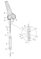
ここで図1を参照して、この図は、本発明の一実施形態に従って構成されるとともに動作可能であり、応力を受けていない状態すなわち静止状態で患者の骨の外側にある骨材料除去装置の簡略側面図および拡大図である。 Now with reference to FIG. 1, this figure is configured and operational according to an embodiment of the invention and is a bone material removing device outside the patient's bone in an unstressed or stationary state. It is a simplified side view and an enlarged view of.
図1は、穴穿孔先端116および彫削部を有する半径方向に突出した周方向穴拡幅要素110の両者を具備する単一の弾性部材が可能な骨材料除去装置100を示している。骨材料除去装置100は、近位端102および遠位端104を有していてもよい。装置100は主に、長手方向軸105に沿って配置されていてもよく、ニチノール等の生体適合性の形状記憶合金で構成されていてもよい。
FIG. 1 shows an
図1の例に示すように、骨材料除去装置100は、任意選択で、その長手方向範囲の大部分が円筒として構成されていてもよい。この円筒は任意選択で、直径が0.5mm~3mmの範囲、この代替および任意選択で0.5mm~2.5mmの範囲、この代替および任意選択で1mm~2mmの範囲であってもよい。
As shown in the example of FIG. 1, the bone
本発明の一実施形態の特定の特徴として、骨材料除去装置100の遠位端104は、任意選択で、遠位対向肩部107で終端する第1の大略円筒部106と、第2の大略円筒部108と、穴穿孔先端116により穿孔された穴の直径から穴拡幅要素が逸脱しないように半径方向にわずかに延びた穴拡幅要素とを有していてもよい。いくつかの実施形態において、穴拡幅要素は、たとえば円錐形状、円弧形状、三角形状、またはその他任意の形状で長手方向軸105に対して半径方向に延びていてもよい。
As a particular feature of one embodiment of the invention, the
図1の実施形態において、穴拡幅要素は、長さ全体に彫削部を具備する大略凸状の外側面112と大略凹状の内側面114とを有する半径方向にわずかに延びた偏心突起110である。他の実施形態において、内側面114は、他の幾何学的形状であってもよい。たとえば、内側面114は、三角形突起110を構成する平坦状であってもよい。突起110は、任意選択で、第1の円筒部106と第2の円筒部108とを接合する。図1に示す実施形態の応力を受けていない位置において、突起110は、任意選択で、0.05~0.4mm、この代替および任意選択で0.075~0.3mm、この代替および任意選択で0.1~0.2mmだけ長手方向軸105から外方に延びていてもよい。
In the embodiment of FIG. 1, the hole widening element is a slightly extending radial
なお、図1の実施形態において、骨材料除去装置100の遠位端104の外径は、骨材料除去装置100のその他の部分の外径よりも小さい。
In the embodiment of FIG. 1, the outer diameter of the
図1に示す実施形態の応力を受けていない位置において、骨材料除去装置100の長手方向範囲の大部分は、半径方向外方に延び得る突起110を除いて、長手方向軸105に沿って配置されている。
In the unstressed position of the embodiment shown in FIG. 1, most of the longitudinal range of the bone
骨材料除去装置100の遠位端104の穴穿孔先端116は、第2の円筒部108から遠位に位置してもよい。
The
なお、任意選択で、遠位端104の長さは、剛性とならないように、たとえば10mmの閾値長さよりも長い。以下により詳しく説明する通り、この特性によれば、穴穿孔先端116と装置100に沿って位置するシャフト捕捉点との間の距離を長くしたり短くしたりすることによって、遠位端104の剛性を必要に応じて変更可能である。言い換えれば、穴穿孔先端116と装置100に沿って位置するシャフト捕捉点との間の距離が短くなると、遠位端104が完全に剛性となる閾値長さ(たとえば、8mm)へと遠位端104の剛性が高まる。
It should be noted that, optionally, the length of the
任意選択で、遠位端104の長さは、10mm~25mm、この代替および任意選択で13mm~23mm、この代替および任意選択で15mm~20mmの範囲であってもよい。
Optionally, the length of the
当然のことながら、図1に見られる骨材料除去装置100の応力を受けていない状態すなわち静止状態において、第1の円筒部106および第2の円筒部108は、長手方向軸105に沿って相互に一致している。
As a matter of course, in the unstressed state, that is, the stationary state of the bone
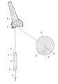
ここで図2を参照して、この図は、応力を受けた状態の図1の骨材料除去装置100の実施形態の側面図および拡大図である。図2に示す例は、たとえば形状記憶合金の材料特性に由来する骨材料除去装置100の弾性の性質を明らかにしたものである。図2に示すように、患者の骨の外側にある骨材料除去装置100は、応力を受けると、弾性的に変形して偏向配向となり得る。ただし、その弾性および形状記憶の性質により、骨材料除去装置100は、応力が解除されると、図1に示す元の応力を受けていない形状すなわち静止状態の形状に戻る可能性がある。
Here, with reference to FIG. 2, this figure is a side view and an enlarged view of an embodiment of the bone
図2に見られる例において、骨材料除去装置100の遠位端104は、当該骨材料除去装置100の弾性特性によって、半径方向に偏向している。第1の円筒部106および第2の円筒部108は、長手方向軸105と一致していない。この段階において骨材料除去装置100である弾性部材の遠位端104の弾性は、穴直径に適合する穴穿孔先端116によって穿孔された穴への遠位端104の収容に対応しており、凸状の外側面112の彫削部のすべてではないが少なくとも頂点が半径方向に突出せず、長手方向軸105と大略一致したままである。
In the example seen in FIG. 2, the
ここで図3を参照して、この図は、カニューレに挿入された図1の骨材料除去装置100について、カニューレが患者の骨上に位置決めされた状態を示した部分切り出し側面図および拡大図である。
Now with reference to FIG. 3, this figure is a partial cut-out side view and an enlarged view showing a state in which the cannula is positioned on the patient's bone for the bone
図3の骨材料除去装置の実施形態は、近位端124にハンドル122を有するとともに遠位端128に長手方向カニューレ126を有し、長手方向軸105に沿って配置された穿孔ガイドツール120に挿入された骨材料除去装置100の一例を示している。カニューレ126は、患者の骨200上の位置に当該カニューレを固定的に位置決めする歯付き先端130を遠位端に有する。穿孔ガイドツール120は、カニューレ126の歯付き先端130が骨200およびカニューレ126に挿入された骨材料除去装置100と係合するように患者の骨200上に位置決めされ、近位円筒部134に沿って延び、内方テーパ部136の近位で終端していてもよい。図3の例において、骨材料除去装置100は、図1と同様の応力を受けていない状態すなわち静止状態で位置決めされたものとして示している。
The embodiment of the bone material removing device of FIG. 3 has a
ここで図4Aを参照して、この図は、カニューレ126に挿入された図1の骨材料除去装置100について、患者の骨200内の第1の動作可能穿孔配向を示した部分切り出し側面図および拡大図である。
Now with reference to FIG. 4A, this figure is a partial cut-out side view showing the first operable perforation orientation in the patient's
カニューレ126は、第1の直径(d1)の内周132を有する近位円筒部134、当該カニューレ126の遠位端128に隣接して位置する内方テーパ部136、およびカニューレ126の遠位端128に位置する第2の直径(d2)の内周を有する円筒部138を有していてもよい。当然のことながら、部分134の内周132の第1の直径は、遠位端128における最遠位円筒部138の第2の直径(d2)より実質的に大きくてもよい。遠位端104を除く骨材料除去装置100の外径(d3)は、カニューレ126の遠位端128の円筒138の内周の第2の直径(d2)と実質的に等しくてもよいため、円筒部138の遠位部128の内周(d2)において、主に半径方向の装置100の軸方向および回転移動、少なくとも固定に対応している。
ここで図4A、図4B、図5A、図5B、および図5Cを参照して、これらの図は、患者の骨200中に遠位前進しているさまざまな時点の骨材料除去装置100の動作段階の例の簡略断面図である。たとえば、静止状態から応力を受けた状態への骨材料除去装置100の遷移またはその逆の遷移による装置100の軸方向移動の半径方向並進への変換および突起100の1つまたは複数の彫削刃の延伸によって、以下に開示の図4A~図5Bの動作段階が穴穿孔装置からアンダーカット生成装置への骨材料除去装置100の変換を示していることが当業者には明らかとなるであろう。これらのステップは一般的に、連続して実行されるようになっていてもよい。
Now with reference to FIGS. 4A, 4B, 5A, 5B, and 5C, these figures show the operation of the bone
図4Aに示すとともに上述の通り、骨材料除去装置100とカニューレ126との間には自由度があり、骨材料除去装置100の弾性特性によって、骨材料除去装置100は、長手方向軸105に沿って長手方向に遠位前進可能である。この自由度は、遠位端104を除く骨材料除去装置100のその他の部分すなわち装置100の最厚部の外径(d3)がカニューレ126の近位円筒部134の第1の直径(d1)よりも実質的に小さいという事実によってもたらされる。
As shown in FIG. 4A and as described above, there is a degree of freedom between the bone
図4Bに示すように、図4Aに示す骨材料除去装置100の挿入段階の時点において、装置100は、カニューレ126の内周132において半径方向に自由に移動可能であるため、部分134の内周132の骨材料除去装置100との接触点(図示せず)が第1のシャフト捕捉を構成可能であり、穿孔先端116の周囲の骨(すなわち、図5の穴202)が第2のシャフト捕捉を構成していてもよい。第1の接触点(捕捉)の特定位置は、穿孔プロセス全体で変動するものであってもよい。また、第1および第2のシャフト捕捉間の距離によって、骨材料除去装置100に第1の曲げモーメントが生じ、図2に示すような応力を受けた状態へと装置100が弾性変形するようになっていてもよい。この状態では、装置100の弾性特性によって、突起110が屈曲力に負けて屈曲し、長手方向軸105ならびに第1の円筒部106および第2の円筒部108と一致して、穴穿孔先端116により穿孔された穴の直径に適合するため、装置100が患者の骨200内で長手方向に前進可能となり、内部に小径穴が形成される。
As shown in FIG. 4B, at the time of the insertion stage of the bone
本発明の一実施形態の特定の特徴として、そのいくつかの実施形態においては、この段階で第1の円筒部106、第2の円筒部108、および突起110が長手方向軸105に沿って相互に一致し、図4Aおよび図4Bに示す動作配向において穴穿孔先端116により穿孔された穴の半径以下の直径を有する一方、遠位対向肩部107は、依然としてカニューレ126の最遠位円筒部138と係合していない。
A particular feature of one embodiment of the invention is that, in some embodiments thereof, the first
図4Aおよび図4Bにおいては、骨材料除去装置100の遠位前進によって、患者の骨200に真っ直ぐな長手方向穴202が形成されている。
In FIGS. 4A and 4B, the distal advancement of the bone
この動作配向において形成された長手方向穴202は、任意選択で、直径が2mm~4mmの範囲、この代替および任意選択で1.5mm~3mmの範囲、この代替および任意選択で1mm~2mmの範囲であり、第1の円筒部106および第2の円筒部108の外径に対応する。
The
ここで図5A、図5B、および図5Cを参照して、これらの図は、カニューレ126に挿入された図1の骨材料除去装置100の実施形態について、患者の骨200内の第2の動作可能穿孔配向を示した部分切り出し側面図、拡大図、および簡略断面図である。
Now with reference to FIGS. 5A, 5B, and 5C, these figures are the second movement within the patient's
図5Aにおいては、骨材料除去装置100が患者の骨200内へとさらに遠位前進している。骨材料除去装置100のさらなる遠位前進としては、約1mm~8mm、この代替および任意選択で1.5mm~7mm、この代替および任意選択で2mm~6mmの範囲が可能である。
In FIG. 5A, the bone
本発明の一実施形態の特定の特徴として、図5Aに示すとともに図5Bにより詳しく示すこの段階では、肩部107およびその装置100の近接部が軸方向にさらに移動して、カニューレ126の最遠位円筒部138に進入しており、骨材料除去装置100とカニューレ126との間には、半径方向の自由度がもはや存在していない。
As a particular feature of one embodiment of the invention, at this stage, shown in FIG. 5A and more detailed in FIG. 5B, the
この自由度は、遠位端104を除く骨材料除去装置100のその他の部分の外径がカニューレ126の最遠位円筒部138の実質的に等しい外径と係合するという事実によって失われる。
This degree of freedom is lost due to the fact that the outer diameter of the rest of the bone
この時点において、穿孔先端116の周囲の骨(すなわち、穴202)は、第2のシャフト捕捉のままであってもよいが、最遠位円筒部138が第3のシャフト捕捉となり、部分134の内周132に沿って接触点に位置する第2のシャフト捕捉に置き換わる。また、第2および第1のシャフト捕捉間の距離よりも短い第1および第3のシャフト捕捉間の距離によって、骨材料除去装置100に第2の小さな曲げモーメントが生じ、遠位端104が完全に剛性となる図5Bに文字(L)で指定の閾値長さ(たとえば、カニューレの先端)となる。
At this point, the bone around the perforation tip 116 (ie, the hole 202) may remain in the second shaft capture, but the most distal
剛性の増大(曲げモーメントの低下)および骨材料除去装置100を構成する材料の形状記憶特性によって、装置100は、図1に示すような元の静止状態へと戻る性質にあるため、図5Bにおいて参照番号550を付した矢印で示す半径方向の力が突起110に加わり、突起110が付勢されて半径方向に延びる。したがって、本発明の一実施形態の特定の特徴として、カニューレ126に対する突起110の形態の穴拡幅要素の軸方向移動により遠位端104の剛性が高まって、突起110の彫削部が半径方向延伸位置へと半径方向に延びる。
In FIG. 5B, the
図5Cに示すように、遠位端104の剛性が高くなると、突起110が半径方向に延びて、長手方向軸105周りの回転により患者の骨200にアンダーカットを実現するため、直径が大きくなり、穴202の直径よりも実質的に大きな直径の穴(アンダーカット)204が形成される。この段階における骨材料除去装置100の剛性により、突起110が長手方向軸105の半径方向外部に突出するため、患者の骨200内で骨材料除去装置100が長手方向に前進可能となって、突起110により形成された外径に対応する大径穴が形成される。
As shown in FIG. 5C, as the
本発明の一実施形態の特定の特徴として、この時点では、図5A~図5Cに示す動作配向において第1の円筒部106および第2の円筒部108が長手方向軸105に沿って相互に一致しており、また、遠位対向肩部107がカニューレ126の最遠位円筒部138と係合して突起110が剛性を失わないようにしているため、長手方向軸105に対して突起110が半径方向外方に延びている。
As a particular feature of one embodiment of the invention, at this point, the first
図5A~図5Cに示す動作配向において形成されたアンダーカット204は、任意選択で、直径が0.6mm~3.2mm、この代替および任意選択で1mm~2.8mm、この代替および任意選択で1.2mm~2.4mmの範囲であり、半径方向に最も延びた構成の突起110の外径に対応する。
The undercut 204 formed in the motion orientation shown in FIGS. 5A-5C has an optional diameter of 0.6 mm to 3.2 mm, an alternative and optional 1 mm to 2.8 mm, and this alternative and optional. It ranges from 1.2 mm to 2.4 mm and corresponds to the outer diameter of the
図5A~図5Cにおいては、骨材料除去装置100のさらなる遠位前進によって、患者の骨200に形成された真っ直ぐな長手方向穴202の大略真ん中にアンダーカット204が形成されている。
In FIGS. 5A-5C, further distal advancement of the bone
ここで図6を参照して、この図は、カニューレ126に挿入された図1の骨材料除去装置の実施形態について、患者の骨200からの骨材料除去装置100の除去を示した部分切り出し側面図および拡大図である。
Now with reference to FIG. 6, this figure shows the removal of the bone
図6においては、骨材料除去装置100が患者の骨200から引き出されているが、骨には、小径の長手方向穴202および大径のアンダーカット204という直径の異なる穴が形成されている。
In FIG. 6, the bone
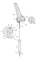
ここで図7を参照して、この図は、本発明の別の実施形態に従って構成されるとともに動作可能な骨材料除去装置300の簡略図である。
Here, with reference to FIG. 7, this figure is a simplified view of the bone
図7においては、任意選択でカニューレの形態で近位端310および遠位端312を有するとともに生体適合性金属で構成された穿孔要素302を骨材料除去装置300が任意選択で具備している。遠位端312は、テーパ穿孔先端314により封止されていてもよい。穿孔要素302は任意選択で、直径が2mm~4mmの範囲、この代替および任意選択で1.5mm~3mmの範囲、この代替および任意選択で1mm~2mmの範囲であってもよい。また、装置300は、穿孔要素302の遠位端312と近位端310との間に配設されるとともに少なくとも一部が挿入された穴拡幅要素304を具備していてもよい。
In FIG. 7, the bone
穿孔要素302は、穴拡幅要素304と接触した押し込み要素308が挿入されたハンドル306と近位端301でつながっている。この代替および任意選択で、穿孔要素302および穴拡幅要素304は、パワーツール(たとえば、パワードリル)に接続可能である。穿孔要素302および穴拡幅要素304は、相互長手方向軸309に沿って配置されている。
The
本発明の一実施形態の特定の特徴として、穴拡幅要素304は、少なくとも一部が穿孔要素302に挿入され、患者の骨に第1の直径の穴を穿孔可能な閉位置と患者の骨に第2の直径の穴を穿孔可能な半径方向に延びた開位置との間で選択的に位置決めされるようになっていてもよく、第1の直径が任意選択で穿孔要素302の管状部またはカニューレ部の外径に等しく、第2の直径が第1の直径よりも大きくて、患者の骨にアンダーカットが形成されるようになっていてもよい。
As a particular feature of one embodiment of the invention, the
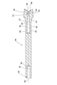
ここで図8Aを参照して、この図は、図7の骨材料除去装置300の穿孔要素302の簡略図である。また、図8Bを参照して、この図は、図8Aの線B-Bに沿った図8Aの穿孔要素302の簡略断面図および拡大図である。
Here, with reference to FIG. 8A, this figure is a simplified view of the
穿孔要素302は任意選択で、生体適合性材料(たとえば、金属)で一体的に構成されるとともに、長手方向軸309に沿って配置されていてもよい。
The
図8Aおよび図8Bにおいては、穿孔要素302の壁335の1つまたは複数の貫通開口320が穿孔要素302を通って半径方向に、長手方向軸309を横切って延びている。穿孔要素302の壁335の内側面336は、開口320の近位に穿孔要素302の中空部を画定するとともに、任意選択で、開口320の遠位に中実部を画定する。
In FIGS. 8A and 8B, one or more through
開口320はそれぞれ、遠位対向肩部322から近位対向肩部324まで長手方向に延びている。
Each of the
当然のことながら、穿孔先端314は、穿孔要素302に対する固定的な結合あるいは一体構成が可能である。
As a matter of course, the
図8Bに見られる例において、穿孔要素302の中実部は、穿孔先端314から近位方向に近位対向肩部324の略隣まで延びて、この場所に近位対向面326を画定する。この面326からは、任意選択で突起328が近位方向に延びている。図8Bに示す突起328は任意選択で、円筒部330と、そこから近位方向に延びた1つまたは複数の傾斜面(たとえば、円錐またはテーパ)を有する近位部332とを有する。当然のことながら、突起328は代替として、その長手方向範囲全体に沿った円錐またはその他任意の拡幅形状(たとえば、ピラミッド状またはその他任意の適当な形状)として構成可能である。図8Aに示す本発明の例示的な実施形態によれば、円錐部332は、1つまたは複数の半径方向に延びる1つまたは複数の遠位延伸テーパ面または傾斜面334を画定する。たとえば、円錐部332は、相互に反対の半径方向に延びる2つの遠位延伸テーパ面または傾斜面334を画定していていもよい。
In the example seen in FIG. 8B, the solid portion of the
穿孔要素302の中空部は、外側面337および内側面336を有する壁335を画定する。
The hollow portion of the
ここで図9Aを参照して、この図は、図7の骨材料除去装置300の穴拡幅要素304の一例の簡略図および簡略断面図である。また、図9Bを参照して、この図は、図9Aの線B-Bに沿った図9Aの穴拡幅要素304の簡略断面図である。
Here, with reference to FIG. 9A, this figure is a simplified view and a simplified cross-sectional view of an example of the
穴拡幅要素304は任意選択で、近位端350および遠位端352を有し、形状記憶の性質を有する弾性の生体適合性材料(たとえば、金属)で一体的に構成可能であるとともに、長手方向軸309に沿って配置可能である。
The
特に、図9Bにおいては、押し込み要素308(図7)が係合する大略円筒状の凹部354が近位端350に形成される。凹部354は、近位端350から遠位方向に延びて、近位対向面356で終端している。
In particular, in FIG. 9B, a substantially
任意選択で、穴拡幅要素304の長手方向範囲の略真ん中から遠位端352まで1つまたは複数の遠位延伸アーム358が延び、近位閉端および遠位開端を有する長手方向凹部360が遠位延伸アーム358の中心対向面に接して遠位延伸アーム358を分離していてもよい。アーム358はそれぞれ、外側面362を画定する。
Optionally, one or more
図9Aおよび図9Bに示すように、穴拡幅要素304のアーム358は、互いに平行ではなく徐々に近づいて、いくつかの例では、長手方向凹部360の近位閉端から遠位で互いに接触していてもよい。以下により詳しく説明する通り、一実施形態において、図9Aおよび図9Bに示す穴拡幅要素304は、半径方向内方の力が外側面362に印加された場合にアーム358が互いに内方へと偏向し得るように、応力を受けない静止状態であってもよい。半径方向外方の力がアーム358の内側面に印加された場合は、アーム358が外方に偏向して、互いにさらに分離可能である。別の実施形態において、図9Aおよび図9Bに示す穴拡幅要素304は、応力を受けた状態すなわち負荷状態であってもよい。
As shown in FIGS. 9A and 9B, the
アーム358はそれぞれ、拡幅要素304の遠位端352に拡幅部364を画定する。拡幅部364はそれぞれ、遠位対向(好適には、内方近位)テーパ面または傾斜面366を画定するのが好ましい。内方近位テーパ面または傾斜面366は、当該面366から近位方向に延びる彫削部368の遠位面を画定する。彫削部368は、大略長手方向に拡幅されて、以下により詳しく説明する外側彫削刃370または複数の彫削刃370と、片側に彫削刃370が接し、骨に対する当該彫削部368の摩擦を防止する端部レリーフまたはクリアランス曲線を形成する半径方向に位置決めされた湾曲面921とを画定しており、装置300の動作に要する力(たとえば、トルク)が抑えられる。長手方向彫削部368は、大略近位内方テーパ面または傾斜面372によって、アーム358の外側面362と接合されている。当然のことながら、長手方向彫削部368としては、円筒あるいは円錐またはその他任意の適当な形状が可能である。
Each
当然のことながら、拡幅部364は、互いにある角度で大略位置決めされていてもよい。
As a matter of course, the widening
いくつかの実施形態において、穴拡幅要素304は、1つまたは複数の彫削部368を備えた単一のアーム358を有していてもよい。他の実施形態において、穴拡幅要素304は、2つ以上のアームを有し、そのうちの1つだけが1つまたは複数の彫削部368を備えていてもよい。
In some embodiments, the
ここで図10と総称する図10A~図10D、図11、および図12と総称する図12A~図12Dを参照して、これらの図は、患者の骨200中に遠位前進しているさまざまな時点の骨材料除去装置300の動作段階の例の簡略図である。たとえば、静止状態から応力を受けた状態への骨材料除去装置300の遷移またはその逆の遷移による装置300の軸方向移動の半径方向並進への変換および1つまたは複数の開口320を通した穴拡幅要素304のアーム358の1つまたは複数の彫削部の延伸によって、以下に開示の動作段階が穴穿孔装置からアンダーカット生成装置への骨材料除去装置300の変換を示していることが当業者には明らかとなるであろう。これらのステップは一般的に、連続して実行されるようになっていてもよい。
With reference to FIGS. 10A-10D, 11 and 12D, collectively referred to herein, FIGS. 12A-12D, these figures are variously advancing distally into the patient's
ここで図10Aを参照して、この図は、閉じた動作配向の図7の組み立てられた骨材料除去装置300の一例を示した2つの異なる簡略平面図(それぞれ、正面図および側面図)である。また、図10Bを参照して、この図は、図10Aの線B-Bに沿った閉じた動作配向の図7の組み立てられた骨材料除去装置300の簡略部分断面図である。さらに図10Cを参照して、この図は、患者の骨内で閉じた動作配向の組み立てられた骨材料除去装置300の簡略側面図である。また、図10Dを参照して、この図は、患者の骨内で閉じた動作配向の組み立てられた骨材料除去装置300を示した図10Cの拡大図である。
Now with reference to FIG. 10A, this figure is a two different simplified plan view (front view and side view, respectively) showing an example of the assembled bone
図10A~図10Dの例においては、長手方向軸309に沿って相互に配置されるように、穴拡幅要素304が穿孔要素302に挿入されている。
In the examples of FIGS. 10A to 10D, the
また、押し込み要素308が依然として完全にはハンドル306に挿入されていないため、穴拡幅要素304は、近位で静止して位置決めされており(図10B)、骨材料除去装置300が閉じた動作配向となる。この近位において、押し込み要素308は、穴拡幅要素304の凹部354の近位対向面356と係合しない。
Also, since the
穴拡幅要素304のアーム358の拡幅部364はそれぞれ、穿孔要素302の各開口320内に位置し、穿孔要素302の開口320により画定された遠位対向肩部322に隣接して、近位内方テーパ面または傾斜面372が位置する。
The widening
穴拡幅要素304の遠位対向(好適には、内方近位)テーパ面または傾斜面366は、穿孔要素302の突起328の遠位延伸テーパ面または傾斜面334と係合しないため、穴拡幅要素304のアーム358は、閉じた静止状態動作配向に位置決めされる。この時点では、アーム358が任意選択で、穿孔要素302の内側面336により穴拡幅要素304のアーム358の拡幅部364の近位内方テーパ面または傾斜面372に印加された半径方向内方の力によって、半径方向内方に、互いに大略わずかに偏向していてもよい。
The distally opposed (preferably inwardly proximal) tapered or
本発明の一実施形態の特定の特徴として、骨材料除去装置300の閉じた動作配向では、穴拡幅要素304の彫削刃370が半径方向にわずかに延びて、穿孔要素302の外側面337とのみ一致するようになっていてもよい。したがって、穿孔要素302の外側面の穿孔半径は、穴拡幅要素304の彫削刃370によって形成される穿孔半径と実質的に等しいため、特に図10Cおよび図10Dに見られるように、患者の骨402に第1の直径の最初の穴400が形成される。
As a particular feature of one embodiment of the invention, in the closed motion orientation of the bone
最初に穿孔される穴の半径としては、たとえば0.2mm~1.4mm、この代替および任意選択で0.4mm~1.2mm、この代替および任意選択で0.5mm~1mmの範囲、またはその他任意の半径が可能であり、好ましくは穿孔要素302の外径に等しい。
The radius of the first hole to be drilled is, for example, 0.2 mm to 1.4 mm, 0.4 mm to 1.2 mm in this alternative and optional, 0.5 mm to 1 mm in this alternative and optional, or otherwise. Any radius is possible, preferably equal to the outer diameter of the
図11は、図10A~図10Dの閉じた配向位置と図12A~図12Dの開いた配向との間の過渡的な動作配向の図7の組み立てられた骨材料除去装置300の実施形態の一例の簡略正面図および部分断面図である。
FIG. 11 is an example of an embodiment of the assembled bone
図11に示す時点においては、押し込み要素308の一部が軸方向に遠位前進しており、一部がハンドル306に挿入されているため、その遠位端が穴拡幅要素304と係合して、穴拡幅要素304を軸方向かつ遠位方向に変位させており、この一部に対して、突起328のテーパ面または傾斜面334が係合する。
At the time point shown in FIG. 11, a part of the pushing
押し込み要素308は、簡易脱着システム、代替あるいは任意選択でのネジ機構により凹部354に取り付けて係止するようにしてもよく、押し込み要素308を回転させることにより必要に応じて、拡幅要素304を軸方向に徐々に移動可能である。
The push-in
軸方向かつ遠位方向に変位した穴拡幅要素304は、軸方向に移動して、穴拡幅要素304の軸方向移動と幾何学的に干渉する突起328の遠位延伸テーパ面または傾斜面334と係合するとともに、半径方向の屈曲力を穴拡幅要素304のアーム358に印加して、彫削部が1つまたは複数の開口320を通って半径方向外方に進行して延びるようにしてもよい。
The axially and distally displaced
ここで図12Aを参照して、この図は、完全に開いた動作配向の図7の組み立てられた骨材料除去装置300を示した2つの異なる簡略平面図(それぞれ、正面図および側面図)である。また、図12Bを参照して、この図は、図12Aの線B-Bに沿った完全に開いた動作配向の図7の組み立てられた骨材料除去装置300の簡略部分断面図である。さらに図12Cを参照して、この図は、患者の骨内で完全に開いた動作配向の組み立てられた骨材料除去装置300の簡略側面図である。また、図12Dを参照して、この図は、患者の骨内で完全に開いた動作配向の組み立てられた骨材料除去装置300を示した図12Cの拡大図である。
Now with reference to FIG. 12A, this figure is in two different simplified plan views (front and side views, respectively) showing the assembled
図12A~図12Dにおいては、長手方向軸309に沿って相互に配置されるように、穴拡幅要素304が穿孔要素302に挿入されたままである。
In FIGS. 12A-12D, the
本発明の一実施形態の特定の特徴として、穴拡幅要素304は、穿孔要素302に対して軸方向に完全に変位している。
As a particular feature of one embodiment of the invention, the
特に、この段階においては、押し込み要素308が完全にハンドル306に挿入されており、遠位端(図示せず)が穴拡幅要素304の凹部354の近位対向面356と係合するため、穴拡幅要素304が軸方向かつ遠位方向に変位して遠位に位置決めされることにより、骨材料除去装置300が開いた動作配向となる。当然のことながら、この代替および任意選択で、ハンドル306および押し込み要素308を利用する代わりに、たとえば押し込み要素308等の機械的手段の操作を要さずにパワーツールの回転方向を変えることで骨材料除去装置300の閉じた動作配向と開いた動作配向とを選択的に変更するパワーツールを使用可能である。
In particular, at this stage, the
穴拡幅要素304の遠位方向の変位によって、穿孔要素302の開口320に対して、穴拡幅要素304のアーム358の拡幅部364が長手軸方向に摺動し、穴拡幅要素304の遠位対向(好適には、内方近位)テーパ面または傾斜面366が穿孔要素302の突起328の遠位延伸テーパ面または傾斜面334と係合するとともに、これに沿って摺動する。これにより、穴拡幅要素304のアーム358間に形成された長手方向凹部360にテーパ面または傾斜面334が進入し、穴拡幅要素304のアーム358の軸方向移動と幾何学的に干渉するため、穴拡幅要素304のアーム358が半径方向外方に偏向する。アーム358は、印加された屈曲力に負けるため、遠位延伸テーパ面または傾斜面334により印加された半径方向外方の力によって互いに離隔し、穴拡幅要素304のアーム358間に形成された長手方向凹部360に進入して、1つまたは複数の開口320を通る彫削部368の半径方向変位および延伸をもたらすため、彫削部368が完全に延びた位置に位置決めされるとともに、骨材料除去装置300が完全に開いた動作配向となる。
Due to the distal displacement of the
図12A~図12Dに示すこの開いた動作配向において、遠位対向(好適には、内方近位)テーパ面または傾斜面366は、穿孔要素302の開口320ならびに突起328の円筒部330によって半径方向延伸位置に係止された彫削部368および彫削刃370により画定された近位対向肩部324に隣接して位置してもよい。これにより、突起328の円筒部330は、彫削部368を延伸位置に支持し、中心を向く半径方向力に対抗するとともに彫削部368が穿孔要素302中に後退することを防止するカウンタ支持部として作用する。
In this open motion orientation shown in FIGS. 12A-12D, the distally opposed (preferably inwardly proximal) tapered or
したがって、本発明の一実施形態の特定の特徴として、突起328に対する穴拡幅要素304の軸方向移動により、穴拡幅要素304のアーム358の1つまたは複数の彫削部368が半径方向延伸位置へと弾性的に半径方向に延伸する。
Therefore, as a specific feature of one embodiment of the present invention, the axial movement of the
本発明の一実施形態の特定の特徴として、骨材料除去装置300の開いた動作配向においては、1つまたは複数の開口320を通って、穴拡幅要素304の彫削刃370が穿孔要素302の外側面337から半径方向外方に延びることにより、彫削刃370が穴の壁から骨を削るとともに骨にアンダーカットを形成するように動作する。このため、穴拡幅要素304の彫削刃370により形成された穿孔直径は、穿孔要素302の穿孔先端314により最初に形成された穿孔直径よりも実質的に大きい。
As a particular feature of one embodiment of the invention, in the open motion orientation of the bone
特に、図12Cおよび図12Dにおいては、患者の骨402における第1の直径の最初の穴400上に第2の直径のアンダーカット404が形成されるが、第2の直径は第1の直径よりも実質的に大きい。アンダーカットの半径としては、たとえば1.5mm~2.5mm、この代替および任意選択で1mm~2mm、この代替および任意選択で0.75mm~1.25mmの範囲が可能である。
In particular, in FIGS. 12C and 12D, a second diameter undercut 404 is formed on the
彫削刃370は一点に向かってテーパ状であってもよいし傾斜していてもよいが、本発明の一実施形態のさらに特定の特徴として、彫削刃370には長さがあり、患者の骨402に形成されたアンダーカット404の長さは、穴拡幅要素304の彫削刃370の長さの関数である。
The
当然のことながら、2つのテーパ面または傾斜面すなわち穴拡幅要素304の遠位対向(任意選択で、内方近位)テーパ面366と穿孔要素302の遠位延伸テーパ面334との係合により、穿孔残留物を凹部360へと除去可能であり、潤滑剤として作用するため、穿孔要素302に対して穴拡幅要素304を滑らかに変位させることができる。
Not surprisingly, by engagement of the two tapered or inclined surfaces or distally opposed (optionally, inwardly proximal) tapered
図12A~図12Dに示されるように、彫削部は任意選択で、穴拡幅要素304のアーム358の単一面に印加された屈曲力により半径方向に延びる。
As shown in FIGS. 12A-12D , the engraved portion is optionally extended radially by the bending force applied to a single surface of the
図9Aおよび図9Bを再び参照して、別の実施形態においては、図9Aおよび図9Bに示す穴拡幅要素304が穿孔要素302の内側で応力を受けた状態すなわち負荷状態であってもよく、穴拡幅要素304のアーム358が応力を受けて互いにある角度となる。
With reference to FIGS. 9A and 9B again, in another embodiment, the
図10Bに示す例の閉位置では、彫削部368の大略近位内方テーパ面372が開口320に付勢され、遠位対向肩部322から長手方向に延び、彫削部368が半径方向に延びないようにする。この時点においては、患者の骨402内に第1の直径の最初の穴400を形成可能である(図10Cおよび図10D)。
In the closed position of the example shown in FIG. 10B, the approximately proximal inwardly tapered
図11に示す時点においては、押し込み要素308の一部が軸方向に遠位前進しており、一部がハンドル306に挿入されているため、その遠位端が穴拡幅要素304と係合して、穴拡幅要素304を軸方向かつ遠位方向に変位させる。また、穿孔要素302に対する穴拡幅要素304の軸方向変位によって、近位内方テーパ面372が遠位対向肩部322と徐々に係合して、その上を摺動する。その弾性および形状記憶の性質により、骨材料除去装置300は、応力が解除されると、図9Aおよび図9Bに示す元の応力を受けていない形状すなわち静止状態の形状に戻る性質があり、穴拡幅要素304のアーム358は、1つまたは複数の開口320を通って半径方向外方に延伸可能である。
At the time point shown in FIG. 11, a part of the pushing
図12A~図12Dにおいては、穿孔要素302に対して穴拡幅要素304が軸方向に完全に変位しており、近位内方テーパ面372がもはや遠位対向肩部322と接触しておらず、これによって制限されることはない。この段階では、図9Aおよび図9Bに示す元の応力を受けていない形状すなわち静止状態の形状へと穴拡幅要素304が完全に戻ることができ、また、穴拡幅要素304のアーム358が1つまたは複数の開口320を通って半径方向外方に完全に延伸可能である。
In FIGS. 12A-12D, the
任意選択で、突起328は、彫削部368を延伸位置に支持し、中心を向く半径方向力に対抗するとともに彫削部368が穿孔要素302中に後退することを防止するカウンタ支持部として作用するようになっていてもよい。
Optionally, the
したがって、本発明の一実施形態の特定の特徴として、突起328に対する穴拡幅要素304の軸方向移動により、元の応力を受けていない形状すなわち静止状態の形状へと穴拡幅要素304が完全に戻ることができ、穴拡幅要素304のアーム358の1つまたは複数の彫削刃が半径方向延伸位置に変位する。
Therefore, as a specific feature of one embodiment of the present invention, the axial movement of the
図9Aを再び参照して、彫削部368は、互いに角度があり、少なくとも一端で接合された1つの彫削刃または2つ以上の彫削刃902および904をそれぞれ具備していてもよい。
With reference to FIG. 9A again , the
第1すなわち主としての彫削刃902は、骨の断片の主要部分を切断して断片の第1の表面を形成するように動作してもよく、第2すなわち補助としての彫削刃904は、断片の第2の隣接面に沿って切断することにより骨の断片を削って取り外すように動作してもよい。
The first or predominantly engraving
図9Aにおいて参照番号950を付した矢印で示す方向に回転した場合、回転方向および主彫削刃902によって画定される先端壁、補助彫削刃904、ならびに両者間の角度は、除去残留物(すなわち、骨の断片)が端部レリーフまたはクリアランス湾曲面921を超えて上昇する(破線矢印952)か、または、遠位対向内方近位テーパ面366に沿って凹部360に収集される(破線矢印954)上に向いた表面を与えるすくい角906を画定していてもよい。また、2つのテーパ面または傾斜面すなわち穴拡幅要素304の遠位対向内方近位テーパ面366と穿孔要素の遠位延伸テーパ面334との係合によって、穿孔残留物が凹部360に進入可能であり、潤滑剤として作用するため、穿孔要素302に対して穴拡幅要素304を滑らかに変位させることができる。
When rotated in the direction indicated by the arrow with
ここで図13Aおよび図13Bを参照して、これらの図は、骨材料除去装置の別の実施形態の簡略断面図である。図13Aは、図7の実施形態と類似する骨材料除去装置1300の一実施形態を示すが、穴拡幅要素1304の1つまたは複数のアーム1302の非彫削端部1310が1つまたは複数の彫削部1306を越えて遠位方向に延び、近位で接することによって、アーム1302の内方近位テーパ面または傾斜面1308で終端する点が図7の実施形態と異なる。
Now with reference to FIGS. 13A and 13B, these figures are simplified cross-sectional views of another embodiment of the bone material removing device. FIG. 13A shows an embodiment of the bone
穿孔要素302に対する穴拡幅要素1304の軸方向移動によって、穴拡幅要素1304の軸方向移動と幾何学的に干渉する突起328とアーム1302の非彫削端部1310の内方近位テーパ面または傾斜面1308が係合するとともに、アーム1302が屈曲して偏向することにより、彫削部1306がカニューレの表面を越えて半径方向に進行して延びるとともに穴の壁から骨を削る。
The inward proximal tapered surface or tilt of the
上記の代替および任意選択で、図13Bに示すように、図7の実施形態と類似する骨材料除去装置1350の一実施形態は、凹部360が近位で狭くて遠位で広く、アーム1302の中心対向面1314がこれに接して画定しており、固定突起1352が中心対向面1314に隣接した配設および/またはアーム1312の2つ以上の中心対向面1314間の凹部360の遠位部内の配設である点が図7の実施形態と異なる。アーム1302の1つまたは複数の非彫削近位部1312は、凹部360の近位境界を起点として、アーム1302から彫削部1306へと延び、遠位でこれが接している。穴拡幅要素1304の軸方向移動によって、穴拡幅要素304の軸方向移動と幾何学的に干渉する突起1352に対して、凹部360を画定するアーム1302の非彫削近位部1312の1つまたは複数の表面が付勢されるとともに、アーム1302が屈曲して偏向することにより、彫削部1306がカニューレの表面を越えて半径方向に進行して延びるとともに穴の壁から骨を削る。
In the alternative and optional alternatives described above, as shown in FIG. 13B, one embodiment of the bone
図10B、図11、図12B、図13A、および図13Bに示すように、彫削部364/1306はそれぞれ、拡幅要素304/1304の1つまたは複数のアーム358/1302の単一面に印加された屈曲力により半径方向に延びる。また、いくつかの実施形態において、1つまたは複数のアーム358/1302が完全に偏向するとともに1つまたは複数の彫削部364/1306が半径方向に完全に延びた場合は、1つまたは複数のアーム358/1302が装置の長手方向軸に対して大略平行であり、彫削部364/1306が突起328等のカウンタ支持部によって支持される。
As shown in FIGS. 10B, 11, 12B, 13A, and 13B, the
骨材料除去装置1400の一実施形態の簡略断面図である図14Aおよび図14Bに示すように、1つまたは複数の彫削部1404を具備する穴拡幅要素1402は、半径方向の移動のみに制限されていてもよく、押し込みロッド1426が付勢されて軸方向に移動することにより穴拡幅要素と係合し、純粋な半径方向に進行する当該穴拡幅要素1402を作動さることにより、彫削部1404が骨材料除去装置1400の表面1406を越えて半径方向に進行して延びるようになっていてもよい。
As shown in FIGS. 14A and 14B, which are simplified cross-sectional views of an embodiment of the bone
図14Aに示すように、骨材料除去装置1400は、その壁1410の開口1408を介して大気と連通したルーメン1428を具備していてもよい。開口1408の遠位縁1412は、骨穿孔先端1414から近位方向に所定の距離で位置してもよく、そこから長手近位方向に開口1408が延びている。長手方向の穴拡幅要素1402は、大略長手方向に拡幅されて1つの外側彫削1416または複数の彫削1416を画定可能な骨彫削部1404を具備していてもよい。また、骨彫削部1404は、片側に彫削刃1416が接し、骨に対する当該彫削部1404の摩擦を防止する端部レリーフまたはクリアランス曲線を形成する半径方向に位置決めされた湾曲面1418を画定していてもよく、穴拡幅装置1400の動作に要する力(たとえば、トルク)が抑えられる。
As shown in FIG. 14A, the bone
長手方向の穴拡幅要素1402は、半径方向内方に一定の張力を印加して、静止時に、骨彫削部1414が少なくとも部分的に骨材料除去装置1400のルーメン1420中に後退し、開口1408の縁内に配設されて突出しないように、穴拡幅要素1402の半径方向外方延伸に耐える弾性取り付け具によって穴拡幅装置1400の壁1410に弾性的に取り付けられていてもよい。
The longitudinal
要素1402の幅にわたって1つまたは複数の細長スロット状の切り欠き1422が切り取られ、切り欠きの長さが骨材料除去装置1400の長手方向軸から半径方向に配向していてもよい。長手方向の穴拡幅要素1402の移動は、壁1410に固定され、半径方向内方、任意選択で切り欠き1422と垂直にこれを通って突出した1つまたは複数のピン1424を含む半径方向ガイド機構によって、半径方向にのみ制限されていてもよい。また、穴拡幅要素1402は、その境界に沿った傾斜面1424または当該要素1402の表面から突出した傾斜面1424を具備していてもよい。
One or more elongated slot-shaped
また、骨材料除去装置1400は、当該骨材料除去装置1400のルーメン1428内で軸方向に移動する押し込みロッド1426を具備していてもよい。任意選択で、押し込みロッド1426の先端1430は、傾斜していてもよい。
Further, the bone
動作時は、押し込みロッド1426が軸方向に移動し、先端1430が傾斜面1424と係合してこれに沿って摺動することにより、穴拡幅要素1402の壁1410への弾性取り付け具によって生じる半径方向内方張力に抗してこれに打ち勝つように作用する半径方向外方の力が印加され、純粋な半径方向に進行して半径方向ガイド機構により制限される穴拡幅要素1402が作動することにより、骨彫削部1404が開口1408を通って周方向に突出し、図14Bに示す完全に延びた骨彫削位置となるようになっていてもよい。
During operation, the
押し込みロッド1426が後退すると、穴拡幅要素1402の壁1410への弾性取り付け具によって生じる張力に抗して傾斜面1424に印加された半径方向外方の力が小さくなり、半径方向外方の反力がその静止状態に戻らず、穴拡幅要素1402がルーメン1428内の後退位置へと半径方向かつ中心方向に付勢され、骨彫削部1414が開口1408の縁内に配設されて突出しなくなる。
When the
彫削部1404は、構造が拡幅彫削部368と類似していてもよく、同様に第1の彫削刃902と、第2の彫削刃904と、および、除去残留物(すなわち、骨の断片)が端部レリーフまたはクリアランス湾曲面921を超えて上昇して骨材料除去装置1400に収集され得る上に向いた表面を与えるすくい角906を画定し得る、両者間の角度とを具備する。
The engraving portion 1404 may be similar in structure to the widening
第1の彫削刃902は、骨の断片の主要部分を切断して断片の第1の表面を形成していてもよく、第2の彫削刃904は、断片の第2の隣接面に沿って切断することにより骨の断片を削って取り外すようにしてもよい。
The
本願に基づく特許の存続期間においては、多くの関連する骨除去機構が開発されることが予想されるため、用語「骨彫削」の範囲は、このようなすべての新技術を先験的に含むものとする。 The scope of the term "bone carving" is a priori to all such new technologies, as many related bone removal mechanisms are expected to be developed for the duration of the patent under this application. It shall include.
本明細書において量または値に言及する場合、用語「およそ(about)」は、「その±15%以内」を意味する。 When referring to a quantity or value herein, the term "about" means "within ± 15% of it."
用語「備える(comprises、comprising)」、「具備する(includes、including)」、「有する(has、having)」、およびそれぞれの活用形は、「非限定的に含む」を意味する。 The terms "comprises, comprising", "includes, including", "has, having", and their respective inflected forms mean "including, but are not limited to".
用語「~からなる(consisting of)」は、「限定的に含む」を意味する。 The term "consisting of" means "limited inclusion".
用語「本質的に~からなる(consisting essentially of)」は、その組成、方法、または構造が別の成分、ステップ、および/または部品を含み得ることを意味するものの、これらの別の成分、ステップ、および/または部品が特許請求の範囲に係る組成、方法、または構造の基本的かつ新規な特性を実質的に変更しない場合に限る。 Although the term "consisting essentially of" means that its composition, method, or structure may comprise another component, step, and / or component, these other components, steps. , And / or only if the component does not substantially alter the basic and novel properties of the claimed composition, method, or structure.
本明細書において、単数形「a」、「an」、および「the」は、別段文脈によって明確に示されない限り、複数表現を含む。たとえば、用語「化合物(a compound)」または「少なくとも1つの化合物(at least one compound)」は、その混合物を含めて、複数の化合物を含み得る。 As used herein, the singular forms "a", "an", and "the" include plural expressions unless expressly indicated by context. For example, the term "a compound" or "at least one compound" may include a plurality of compounds, including a mixture thereof.
本願の全体を通して、本発明の実施形態は、範囲形式を参照して表される場合がある。範囲形式での記述は、利便性および簡便性を目的としているに過ぎず、本発明の範囲に対する絶対的な制限と解釈されるべきではないことが了解されるものとする。したがって、範囲の記述は、当該範囲内の考え得るすべての部分的範囲および個別の数値を具体的に開示したものと考えられるべきである。たとえば、「1~6」等の範囲の記述は、「1~3」、「1~4」、「1~5」、「2~4」、「2~6」、「3~6」等の部分的範囲のほか、たとえば1、2、3、4、5、および6等、当該範囲内の個々の数値を具体的に開示したものと考えられるべきである。このことは、範囲の幅とは無関係に当てはまる。 Throughout the present application, embodiments of the present invention may be expressed with reference to a range form. It is to be understood that the description in range format is for convenience and convenience only and should not be construed as an absolute limitation on the scope of the invention. Therefore, the description of a range should be considered as a specific disclosure of all possible partial ranges and individual numbers within that range. For example, the description of the range such as "1 to 6" is "1 to 3", "1 to 4", "1 to 5", "2 to 4", "2 to 6", "3 to 6", etc. In addition to the partial range of, it should be considered that the individual numerical values within the range are specifically disclosed, for example, 1, 2, 3, 4, 5, and 6. This is true regardless of the width of the range.
本明細書において数値範囲(たとえば、「10-15」、「10から15まで(10 to 15)」、または別の範囲指示により連結された任意対の数字)が指定されている場合は常に、別段文脈によって明確に示されない限り、範囲境界も含めて、指定された範囲境界内の任意の数字(小数または整数)を含むものとする。本明細書において、第1の指示数と第2の指示数との間の「範囲(range/ranging/ranges)」および第1の指示数から第2の指示数まで(「to」、「up to」、「until」、「through」、または別の範囲指示語)の「範囲(range/ranging/ranges)」という表現は、区別なく使用しており、第1および第2の指示数ならびに両者間のすべての小数および整数を含むものである。 Whenever a numerical range is specified herein (eg, "10-15", "10 to 15 (10 to 15)", or any pair of numbers concatenated by another range indication). Unless explicitly stated in the context, it shall include any number (decimal or integer) within the specified range boundaries, including range boundaries. In the present specification, the "range / ranking / ranges" between the first instruction number and the second instruction number and the first instruction number to the second instruction number ("to", "up"). The expression "range / ranking / ranges" in "to", "intil", "throw", or another range demonstrative) is used interchangeably, with the first and second indications and both. Contains all decimals and integers between.
別段示されない限り、本明細書で使用する数値およびそれらに基づく任意の数値範囲は、当業者が理解する妥当な測定結果および丸め誤差の精度範囲での近似値である。 Unless otherwise indicated, the numbers used herein and any numerical range based on them are reasonable approximations to the accuracy range of reasonable measurement results and rounding errors understood by those of skill in the art.
本明細書において、用語「方法(method)」は、所与の課題を達成する様態、手段、技術、および手順を表しており、化学、薬理学、生物学、生物化学、および医学の熟練者に既知または既知の様態、手段、技術、および手順から容易に開発可能な様態、手段、技術、および手順を含むが、これらに限定されない。 As used herein, the term "method" refers to a mode, means, technique, and procedure for accomplishing a given task and is an expert in chemistry, pharmacology, biology, biochemistry, and medicine. Includes, but is not limited to, modes, means, techniques, and procedures that can be easily developed from known or known modes, means, techniques, and procedures.
本明細書において、用語「処置(treating)」は、状態の進行の無効化、実質的な阻止、低速化、もしくは反転、状態の臨床的もしくは美的症状の実質的な改善、または状態の臨床的もしくは美的症状の出現の実質的な防止を含む。 As used herein, the term "treating" is used to nullify, substantially prevent, slow down, or reverse the progression of a condition, substantially improve the clinical or aesthetic symptoms of the condition, or clinically. Or it includes substantial prevention of the appearance of aesthetic symptoms.
当然のことながら、本発明の特定の特徴は、明瞭化のため、個々の実施形態の背景において説明したが、1つの実施形態において組み合わせて提供可能である。逆に、本発明の種々特徴は、簡潔化のため、1つの実施形態の背景において説明したが、別個の提供、任意適当な部分的組み合わせでの提供、または本発明のその他任意の上記実施形態に適したものとしての提供も可能である。種々実施形態の背景において説明した特定の特徴は、当該要素なしで無効とならない限り、上記実施形態の本質的な特徴とは考えられないものとする。 Of course, certain features of the invention have been described in the context of the individual embodiments for clarity, but can be provided in combination in one embodiment. Conversely, various features of the invention have been described in the context of one embodiment for brevity, but may be provided separately, provided in any suitable partial combination, or any other embodiment of the invention. It is also possible to provide it as suitable for. The particular features described in the background of the various embodiments are not considered to be essential features of the embodiments unless invalidated without the element.
以上、具体的な実施形態と併せて本発明を説明したが、当業者には当然のことながら、多くの変更、改良、および変形が明らかである。したがって、添付の特許請求の範囲の主旨および広い範囲に含まれるこのようなすべての変更、改良、および変形が包含されるものとする。 Although the present invention has been described above with specific embodiments, many changes, improvements, and modifications are apparent to those skilled in the art, as a matter of course. Accordingly, all such changes, improvements, and modifications contained in the spirit and scope of the appended claims shall be included.
本明細書に記載のすべての刊行物、特許、および特許出願は、各個別の刊行物、特許、または特許出願の具体的かつ個別の援用指示と同じ程度まで、そのすべての内容を本明細書に援用する。また、本出願における如何なる参考文献の引用または特定も、このような参考文献が本発明の先行技術として利用可能であることを認めるものとして解釈されないものとする。項目見出しは、その使用の限りにおいて、必ずしも限定的に解釈されるべきではない。 All publications, patents, and patent applications described herein are to the same extent as the specific and individual reference instructions of each individual publication, patent, or patent application. Invite to. In addition, any citation or identification of any reference in this application shall not be construed as recognizing that such reference is available as prior art of the invention. Item headings should not necessarily be construed in a limited way, to the extent of their use.
[関連出願]
本願は、米国特許法第119条(e)の下、2015年4月9日に出願された米国仮特許出願第62/144,991号および2015年4月22日に出願された米国仮特許出願第62/151,375号の優先権の利益を主張するものであり、これらのすべての内容を参照により本明細書に援用する。
[Related application]
This application is a US provisional patent application No. 62 / 144,991 filed on April 9, 2015 and a US provisional patent filed on April 22, 2015 under Article 119 (e) of the US Patent Act. It claims the benefit of the priority of Application No. 62 / 151,375, all of which is incorporated herein by reference.
Claims (31)
中空部および長軸を有するカニューレと、
前記カニューレの前記中空部内に位置し、軸方向に細長く延伸した干渉要素と、
前記カニューレの前記中空部内を前記長軸に沿って前記干渉要素に対して軸方向移動するように構成された穴拡幅要素と、
前記穴拡幅要素に結合された骨彫削部であって、
前記長軸から半径方向外向きに向く主としての切断刃と、
補助としての切断刃であって、前記主としての切断刃と前記補助としての切断刃とは、互いに対して角度をなし、少なくとも一端において接合された、補助としての切断刃と、
前記補助としての切断刃が接し、遠位対向面である、クリアランス面と、
を有する、骨彫削部と、
を備え、
前記軸方向移動によって、前記干渉要素が前記穴拡幅要素と係合し前記長軸に関して半径方向外向きの力が前記穴拡幅要素に印加し、前記半径方向外向きの力によって、前記主としての切断刃および前記補助としての切断刃の少なくとも1つは、後退位置から、前記主としての切断刃および前記補助としての切断刃の少なくとも1つが前記カニューレの外側面を超えて前記長軸から半径方向外向きに延伸する延伸位置に、前記長軸から半径方向外向きに延びる、
装置。 A device for removing bone from the wall of a hole
With a cannula with a hollow and a long axis,
Interfering elements located in the hollow portion of the cannula and elongated in the axial direction,
A hole widening element configured to move axially with respect to the interfering element along the long axis in the hollow portion of the cannula.
A bone carving portion coupled to the hole widening element.
The main cutting blade that faces outward in the radial direction from the long axis,
An auxiliary cutting blade, wherein the main cutting blade and the auxiliary cutting blade are angled with respect to each other and are joined at at least one end to form an auxiliary cutting blade.
The clearance surface, which is the distal facing surface to which the auxiliary cutting blade is in contact,
With a bone carving part,
Equipped with
Due to the axial movement, the interfering element engages with the hole widening element, a radial outward force is applied to the hole widening element with respect to the long axis, and the radial outward force causes the main cutting. At least one of the blade and the auxiliary cutting blade is radially outward from the major axis beyond the outer surface of the cannula with at least one of the predominantly cutting blade and the auxiliary cutting blade from the retracted position. Radially outwardly extending from the long axis at the stretching position.
Device.
前記骨彫削部は、前記自由端に結合される、
請求項1から3のいずれか一項に記載の装置。 The hole widening element is an arm oriented in the major axis direction and includes an arm having a free end facing the interfering element.
The bone carving is coupled to the free end.
The device according to any one of claims 1 to 3.
請求項4に記載の装置。 When the arm is completely deflected outward, the arm is parallel to the major axis of the device and the blade of the bone carving is supported by the counter support of the interfering element.
The device according to claim 4.
前記クリアランス面は、傾斜面であり、
前記干渉要素は、前記前方先端および前記穴拡幅要素の間を近位方向に延び、
前記アームの自由端は、遠位に延び、前記傾斜面は、前記自由端の遠位面において前記長軸に対向し、
前記軸方向移動によって、前記穴拡幅要素の前記軸方向移動と幾何学的に干渉する前記干渉要素は、前記傾斜面と係合するとともに、前記アームが屈曲して、前記骨彫削部が前記長軸から半径方向外向きに偏向する、
請求項4から6のいずれか一項に記載の装置。 Further including the anterior tip of the distal end of the cannula,
The clearance surface is an inclined surface and is an inclined surface.
The interfering element extends proximally between the anterior tip and the hole widening element.
The free end of the arm extends distally and the tilted surface faces the major axis in the distal surface of the free end.
The interfering element, which geometrically interferes with the axial movement of the hole widening element due to the axial movement, engages with the inclined surface, the arm is bent, and the bone carving portion is described. Deflection outward from the long axis in the radial direction,
The apparatus according to any one of claims 4 to 6.
前記軸方向移動によって、前記干渉要素は、前記細長いアームと係合し、前記長軸に関して半径方向外向きの屈曲力を、前記細長いアームに印加し、
前記半径方向外向きの屈曲力によって、前記細長いアームが屈曲し、前記主としての切断刃および前記補助としての切断刃の少なくとも1つは、前記後退位置から前記延伸位置に前記長軸から半径方向外向きに延びる、請求項4から7のいずれか一項に記載の装置。 The arm is elongated
Due to the axial movement, the interfering element engages with the elongated arm and applies a radial outward bending force with respect to the long axis to the elongated arm.
Due to the radial outward bending force, the elongated arm is bent, and at least one of the main cutting blade and the auxiliary cutting blade is radially out of the long axis from the retracted position to the extended position. The device according to any one of claims 4 to 7, which extends in a direction.
前記軸方向移動によって、前記干渉要素は、前記細長いアームと係合し、前記干渉要素は、前記長軸に関して半径方向外向きの偏向力を、前記細長いアームに印加し、
前記半径方向外向きの屈曲力によって、前記細長いアームが偏向し、前記主としての切断刃および前記補助としての切断刃の少なくとも1つは、前記後退位置から、前記主としての切断刃が前記長軸に平行である前記延伸位置に前記長軸から半径方向外向きに延びる、請求項4から7のいずれか一項に記載の装置。 The arm is elongated
Due to the axial movement, the interfering element engages with the elongated arm, which applies a radial outward deflection force with respect to the long axis to the elongated arm.
The radial outward bending force deflects the elongated arm so that at least one of the main cutting blade and the auxiliary cutting blade is from the retracted position with the main cutting blade on the long axis. The device according to any one of claims 4 to 7, which extends outward in the radial direction from the long axis to the extending position which is parallel.
前記骨彫削部の少なくとも一部は、前記延伸位置において、前記少なくとも1つの開口を通って周方向に延びる、
請求項1から12のいずれか一項に記載の装置。 The cannula further comprises at least one through opening in the wall of the hollow portion of the cannula.
At least a portion of the bone carving portion extends circumferentially through the at least one opening at the stretching position.
The apparatus according to any one of claims 1 to 12.
前記穴拡幅要素は、応力を受けた状態で前記カニューレ内部に収容され、
前記干渉要素の前記穴拡幅要素との係合によって、前記干渉要素は、前記主としての切断刃および前記補助としての切断刃の少なくとも1つの前記後退位置から前記延伸位置への前記延伸を引き起こすように、前記傾斜する少なくとも1つの面を前記カニューレの少なくとも1つの開口の遠位対向肩部に対してその上方に付勢する、請求項13に記載の装置。 The bone carving section comprises at least one surface that is inclined inwardly proximal to the major axis.
The hole widening element is housed inside the cannula under stress.
By engaging the interfering element with the hole widening element, the interfering element causes the stretching from at least one retracting position of the predominantly cutting blade and the auxiliary cutting blade to the stretching position. 13. The device of claim 13, wherein the tilted at least one surface is urged above the distally opposed shoulder of at least one opening of the cannula.
前記円筒部の内周の直径は、前記単一の弾性部材の軸方向および回転方向移動を支持し半径方向移動を制限する、前記単一の弾性部材の半径方向最厚部の外径と等しい、請求項16および18のいずれか一項に記載の装置。 It has a cylindrical portion located at the distal end of the cannula.
The diameter of the inner circumference of the cylindrical portion is equal to the outer diameter of the thickest radial portion of the single elastic member that supports axial and rotational movement of the single elastic member and limits radial movement. , The apparatus according to any one of claims 16 and 18.
前記半径方向外向きの力によって、前記主としての切断刃は、前記後退位置から前記延伸位置に前記長軸から半径方向外向きに延び、
前記アームは、ヒンジなし機構を使用して半径方向外向きに屈曲する、請求項4に記載の装置。 Due to the axial movement, the interfering element engages with the hole widening element, and the interfering element applies a radial outward force with respect to the axial direction to the hole widening element.
Due to the radial outward force, the main cutting blade extends radially outward from the long axis from the retracted position to the extended position.
The device of claim 4, wherein the arm bends outward in the radial direction using a hingeless mechanism.
前記長手方向凹部は、閉端および前記干渉要素に対向する開端を備え、前記骨彫削部は、前記長手方向凹部の前記開端に向かう前記第1のアームに結合される、
請求項1から3および10から26のいずれか一項に記載の装置。 The hole widening element comprises a first arm and a second arm separated by a longitudinal recess extending parallel to the major axis.
The longitudinal recess comprises a closed end and an open end facing the interfering element, and the bone carving is coupled to the first arm towards the open end of the longitudinal recess.
The apparatus according to any one of claims 1 to 3 and 10 to 26 .
前記軸方向移動によって、前記干渉要素が前記複数のアームと係合し、前記複数のアームの間に形成された長手方向凹部に進入し、前記長軸に関して半径方向外向きの屈曲力を前記複数のアームに印加し、
前記半径方向外向きの屈曲力によって、前記複数のアームが屈曲し、前記主としての切断刃および前記補助としての切断刃の少なくとも1つは、前記後退位置から前記延伸位置に前記長軸から半径方向外向きに延びる、請求項1から3および10から26のいずれか一項に記載の装置。 The hole widening element comprises a plurality of arms and
Due to the axial movement, the interfering element engages with the plurality of arms, enters a longitudinal recess formed between the plurality of arms, and exerts a radial outward bending force with respect to the long axis. Apply to the arm of
The radial outward bending force causes the plurality of arms to bend, and at least one of the main cutting blade and the auxiliary cutting blade is radially from the long axis to the extending position from the retracted position. The device according to any one of claims 1 to 3 and 10 to 26 , which extends outward.
中空部および長軸を有するカニューレと、
前記カニューレの前記中空部内に位置し、軸方向に細長く延伸した干渉要素と、
前記カニューレの前記中空部内を前記長軸に沿って前記干渉要素に対して軸方向移動するように構成された穴拡幅要素と、
前記穴拡幅要素に結合された骨彫削部であって、前記長軸から半径方向外向きに向く切断刃と前記切断刃に接するクリアランス面とを有し、前記クリアランス面は、前記長軸から半径方向外向きに向き、前記長軸の周りに周方向に湾曲する、骨彫削部と、
を備え、
前記軸方向移動によって、前記干渉要素が前記穴拡幅要素と係合し前記長軸に関して半径方向外向きの力が前記穴拡幅要素に印加し、前記半径方向外向きの力によって、前記切断刃は、後退位置から、前記切断刃が前記カニューレの外側面を超えて前記長軸から半径方向外向きに延伸する延伸位置に、前記長軸から半径方向外向きに延び、
前記延伸位置における前記長軸に対する前記切断刃の角度は、前記後退位置における前記長軸に対する前記切断刃の角度と同じである、
装置。 A device for removing bone from the wall of a hole
With a cannula with a hollow and a long axis,
Interfering elements located in the hollow portion of the cannula and elongated in the axial direction,
A hole widening element configured to move axially with respect to the interfering element along the long axis in the hollow portion of the cannula.
A bone carving portion coupled to the hole widening element, which has a cutting blade that faces outward in the radial direction from the long axis and a clearance surface that is in contact with the cutting blade, and the clearance surface is from the long axis. A bone carving part that faces outward in the radial direction and curves in the circumferential direction around the long axis.
Equipped with
Due to the axial movement, the interfering element engages with the hole widening element, a radial outward force is applied to the hole widening element with respect to the long axis, and the radial outward force causes the cutting blade to move. From the retracted position, the cutting blade extends radially outward from the major axis to an extension position where the cutting blade extends radially outward from the major axis beyond the outer surface of the cannula.
The angle of the cutting blade with respect to the long axis at the stretching position is the same as the angle of the cutting blade with respect to the long axis at the retracting position.
Device.
Priority Applications (2)
| Application Number | Priority Date | Filing Date | Title |
|---|---|---|---|
| JP2022001060A JP2022043309A (en) | 2015-04-09 | 2022-01-06 | Bone material removal device |
| JP2024003421A JP2024029236A (en) | 2015-04-09 | 2024-01-12 | Bone material removal device |
Applications Claiming Priority (5)
| Application Number | Priority Date | Filing Date | Title |
|---|---|---|---|
| US201562144991P | 2015-04-09 | 2015-04-09 | |
| US62/144,991 | 2015-04-09 | ||
| US201562151375P | 2015-04-22 | 2015-04-22 | |
| US62/151,375 | 2015-04-22 | ||
| PCT/IL2016/050370 WO2016162869A2 (en) | 2015-04-09 | 2016-04-07 | Bone material removal device and a method for use thereof |
Related Child Applications (1)
| Application Number | Title | Priority Date | Filing Date |
|---|---|---|---|
| JP2022001060A Division JP2022043309A (en) | 2015-04-09 | 2022-01-06 | Bone material removal device |
Publications (3)
| Publication Number | Publication Date |
|---|---|
| JP2018513735A JP2018513735A (en) | 2018-05-31 |
| JP2018513735A5 JP2018513735A5 (en) | 2019-05-16 |
| JP7007190B2 true JP7007190B2 (en) | 2022-01-24 |
Family
ID=57073130
Family Applications (3)
| Application Number | Title | Priority Date | Filing Date |
|---|---|---|---|
| JP2017552067A Active JP7007190B2 (en) | 2015-04-09 | 2016-04-07 | Bone material remover and how to use it |
| JP2022001060A Pending JP2022043309A (en) | 2015-04-09 | 2022-01-06 | Bone material removal device |
| JP2024003421A Pending JP2024029236A (en) | 2015-04-09 | 2024-01-12 | Bone material removal device |
Family Applications After (2)
| Application Number | Title | Priority Date | Filing Date |
|---|---|---|---|
| JP2022001060A Pending JP2022043309A (en) | 2015-04-09 | 2022-01-06 | Bone material removal device |
| JP2024003421A Pending JP2024029236A (en) | 2015-04-09 | 2024-01-12 | Bone material removal device |
Country Status (5)
| Country | Link |
|---|---|
| US (3) | US10448959B2 (en) |
| EP (1) | EP3282956A4 (en) |
| JP (3) | JP7007190B2 (en) |
| CN (1) | CN107530091B (en) |
| WO (1) | WO2016162869A2 (en) |
Families Citing this family (11)
| Publication number | Priority date | Publication date | Assignee | Title |
|---|---|---|---|---|
| EP3326552B1 (en) | 2013-04-24 | 2023-02-22 | T.A.G. Medical Devices - Agriculture Cooperative Ltd. | Bone material removal devices |
| US11219466B2 (en) * | 2018-06-06 | 2022-01-11 | Acumed Llc | Orthopedic reamer with expandable cutting head |
| ES2950085T3 (en) | 2014-10-19 | 2023-10-05 | T A G Medical Products Corp Ltd | A kit that includes a guidance system and a bone material extraction device |
| EP3282956A4 (en) | 2015-04-09 | 2019-01-16 | T.A.G. Medical Devices - Agriculture Cooperative Ltd. | Bone material removal device and a method for use thereof |
| CN108289688B (en) * | 2015-11-17 | 2021-07-20 | 伦克巴尔有限责任公司 | Surgical access instrument with expandable section |
| EP3799806A1 (en) | 2016-02-11 | 2021-04-07 | T.A.G. Medical Devices - Agriculture Cooperative Ltd. | Bone material removal device |
| US11020132B2 (en) | 2016-04-24 | 2021-06-01 | T.A.G. Medical Devices—Agriculture Cooperative Ltd. | Guiding device and method of using thereof |
| CN110709019B (en) * | 2017-06-22 | 2023-12-26 | 史密夫和内修有限公司 | Surgical drill guide and system |
| US11026669B2 (en) * | 2017-07-13 | 2021-06-08 | Medtronic Vascular, Inc. | Collapsible dilator |
| WO2020026252A2 (en) | 2018-08-01 | 2020-02-06 | T.A.G. Medical Devices - Agriculture Cooperative Ltd. | Adjustable drilling device and a method for use thereof |
| CN111202598B (en) * | 2020-02-26 | 2021-05-04 | 四川大学 | A car needle for hindering life wisdom tooth pulls out |
Citations (3)
| Publication number | Priority date | Publication date | Assignee | Title |
|---|---|---|---|---|
| JP2006523542A (en) | 2003-04-17 | 2006-10-19 | セカント メディカル エルエルシー | Tool with expandable cutting edge |
| US20080114364A1 (en) | 2006-11-15 | 2008-05-15 | Aoi Medical, Inc. | Tissue cavitation device and method |
| WO2014089198A1 (en) | 2012-12-05 | 2014-06-12 | Smith & Nephew, Inc. | Surgical instrument |
Family Cites Families (140)
| Publication number | Priority date | Publication date | Assignee | Title |
|---|---|---|---|---|
| US854956A (en) | 1906-11-16 | 1907-05-28 | Charles F Martin | Veterinary surgical instrument. |
| US1006468A (en) * | 1911-01-09 | 1911-10-24 | Leonard H Des Isles | Fastener for railway-rails. |
| US1106767A (en) * | 1913-07-10 | 1914-08-11 | Edwin C Miller | Rail-holding device. |
| US1204330A (en) * | 1915-03-04 | 1916-11-07 | Adolphus G Adair | Rail-spike. |
| US1173882A (en) * | 1915-07-16 | 1916-02-29 | Clarence O Smith | Railroad-spike. |
| US1237142A (en) * | 1916-11-18 | 1917-08-14 | Karl L Aase | Spike. |
| US1958399A (en) | 1932-06-03 | 1934-05-08 | Natural Food Products Company | Reamer for citrus fruits |
| US3195378A (en) * | 1957-08-07 | 1965-07-20 | Cogsdill Tool Prod | Cutting tool |
| GB1090350A (en) | 1965-03-12 | 1967-11-08 | Eriksbergs Mek Verstads Aktieb | Rotary cutting tool |
| US3690357A (en) | 1970-07-07 | 1972-09-12 | Roberto Lugo | Adjustable depth groove cutter and support therefor |
| US3702611A (en) | 1971-06-23 | 1972-11-14 | Meyer Fishbein | Surgical expansive reamer for hip socket |
| JPS4862067A (en) | 1971-12-01 | 1973-08-30 | ||
| US3945076A (en) | 1974-12-10 | 1976-03-23 | Thomas Sung | Circular toothbrush |
| DE3024656C2 (en) * | 1980-06-30 | 1982-08-12 | Heinrich 6102 Pfungstadt Liebig | Undercut drilling tool |
| US4475852A (en) * | 1981-12-24 | 1984-10-09 | Santrade Ltd. | Retractable rotary cutting tool |
| US4541423A (en) | 1983-01-17 | 1985-09-17 | Barber Forest C | Drilling a curved hole |
| US4635737A (en) * | 1984-03-08 | 1987-01-13 | Kabushiki Kaishi Miyanaga | Undercutting drill |
| SE455843B (en) | 1985-02-15 | 1988-08-15 | Erix Tool Ab | BACKGROUND TOOLS WITH A PENDING STORAGE WING |
| US4738255A (en) * | 1986-04-07 | 1988-04-19 | Biotron Labs, Inc. | Suture anchor system |
| US4883048A (en) | 1986-10-03 | 1989-11-28 | Purnell Mark L | Apparatus and method for use in performing a surgical operation |
| US4920958A (en) | 1986-11-05 | 1990-05-01 | Minnesota Mining And Manufacturing Company | Drill guide assembly |
| DE3839617A1 (en) | 1988-11-24 | 1990-05-31 | Fischer Artur Werke Gmbh | DEVICE FOR PRODUCING AN UNDERCUT IN A DRILL HOLE |
| JP2598515B2 (en) * | 1989-04-24 | 1997-04-09 | 株式会社ミヤナガ | Hole punching device with enlarged diameter |
| CA2007210C (en) * | 1989-05-10 | 1996-07-09 | Stephen D. Kuslich | Intervertebral reamer |
| US5112337A (en) | 1991-02-05 | 1992-05-12 | Depuy Du Pont Orthopaedics | Variable angle, selective length tibial drill guide |
| US5681320A (en) | 1991-12-13 | 1997-10-28 | Mcguire; David A. | Bone-cutting guide |
| US5330468A (en) | 1993-10-12 | 1994-07-19 | Burkhart Stephen S | Drill guide device for arthroscopic surgery |
| US6716216B1 (en) | 1998-08-14 | 2004-04-06 | Kyphon Inc. | Systems and methods for treating vertebral bodies |
| US5645589A (en) * | 1994-08-22 | 1997-07-08 | Li Medical Technologies, Inc. | Anchor and method for securement into a bore |
| US5514136A (en) | 1994-09-06 | 1996-05-07 | Wright Medical Technology, Inc. | Surgical instrument for driving and rotating a long bone prosthesis |
| US5591170A (en) * | 1994-10-14 | 1997-01-07 | Genesis Orthopedics | Intramedullary bone cutting saw |
| GB2297052B (en) * | 1995-01-23 | 1998-02-18 | David Patrick Payne | Improvements in drills |
| US5643273A (en) | 1995-02-17 | 1997-07-01 | Clark; Ron | ACL bone tunnel projection drill guide and method for its use |
| US5507606A (en) | 1995-05-04 | 1996-04-16 | R. Steiner Technologies, Inc. | Back spotfacing tool |
| EP0859570A4 (en) | 1995-10-30 | 2000-03-15 | Biomedical Enterprises Inc | Materials collection system and uses thereof |
| US5817095A (en) * | 1996-02-22 | 1998-10-06 | Smith & Nephew, Inc. | Undercutting surgical instrument |
| US5885258A (en) * | 1996-02-23 | 1999-03-23 | Memory Medical Systems, Inc. | Medical instrument with slotted memory metal tube |
| DE19634484C1 (en) | 1996-08-26 | 1998-04-02 | Plus Endoprothetik Ag | Bone cutter |
| JP3611934B2 (en) | 1996-10-23 | 2005-01-19 | メイラ株式会社 | Bone drilling device for ligament reconstruction |
| US5839860A (en) | 1996-12-31 | 1998-11-24 | R. Steiner Technolgoies, Inc. | Intertially activated spotfacing and counterboring tool |
| IL128261A0 (en) | 1999-01-27 | 1999-11-30 | Disc O Tech Medical Tech Ltd | Expandable element |
| US6120511A (en) | 1997-11-18 | 2000-09-19 | Chan; Kwan-Ho | Drill guide assembly and method for producing a bone tunnel |
| WO2001028469A2 (en) | 1999-10-21 | 2001-04-26 | Sdgi Holdings, Inc. | Devices and techniques for a posterior lateral disc space approach |
| JP2001219312A (en) | 2000-02-09 | 2001-08-14 | Matsuda Ika Kk | Drill for drilling lateral hole |
| US6383188B2 (en) | 2000-02-15 | 2002-05-07 | The Spineology Group Llc | Expandable reamer |
| US20030191474A1 (en) | 2000-02-16 | 2003-10-09 | Cragg Andrew H. | Apparatus for performing a discectomy through a trans-sacral axial bore within the vertebrae of the spine |
| US6210415B1 (en) | 2000-02-18 | 2001-04-03 | Lab Engineering & Manufacturing, Inc. | Surgical drill guide |
| US7485119B2 (en) | 2000-03-07 | 2009-02-03 | Zimmer Technology, Inc. | Method and apparatus for reducing femoral fractures |
| US6358251B1 (en) | 2000-03-21 | 2002-03-19 | University Of Washington | Method and apparatus for forming a cavity in soft tissue or bone |
| US6375658B1 (en) | 2000-04-28 | 2002-04-23 | Smith & Nephew, Inc. | Cartilage grafting |
| US6679886B2 (en) | 2000-09-01 | 2004-01-20 | Synthes (Usa) | Tools and methods for creating cavities in bone |
| US7594917B2 (en) | 2001-03-13 | 2009-09-29 | Ethicon, Inc. | Method and apparatus for fixing a graft in a bone tunnel |
| CN2469895Y (en) | 2001-03-21 | 2002-01-09 | 王玉山 | Sneak-dilating decompressor for head of femur |
| US7927332B2 (en) | 2004-11-12 | 2011-04-19 | Acumed Llc | Bone reamer |
| US6746451B2 (en) | 2001-06-01 | 2004-06-08 | Lance M. Middleton | Tissue cavitation device and method |
| US6814734B2 (en) | 2001-06-18 | 2004-11-09 | Sdgi Holdings, Inc, | Surgical instrumentation and method for forming a passage in bone having an enlarged cross-sectional portion |
| US8142365B2 (en) | 2002-05-31 | 2012-03-27 | Vidacare Corporation | Apparatus and method for accessing the bone marrow of the sternum |
| US7828804B2 (en) | 2002-11-08 | 2010-11-09 | Warsaw Orthopedic, Inc. | Transpedicular intervertebral disk access methods and devices |
| US7172374B2 (en) | 2002-12-30 | 2007-02-06 | Cogsdill Tool Products, Inc. | Backspot facing tool |
| JP4555293B2 (en) | 2003-09-03 | 2010-09-29 | カイフォン・ソシエテ・ア・レスポンサビリテ・リミテ | Device and associated method for creating a cavity in an internal body region |
| EP1845890A4 (en) | 2003-11-20 | 2010-06-09 | Arthrosurface Inc | System and method for retrograde procedure |
| US20050113836A1 (en) * | 2003-11-25 | 2005-05-26 | Lozier Antony J. | Expandable reamer |
| EP1712194B1 (en) * | 2004-02-05 | 2009-12-09 | Bti, I+D, S.L. | Tools for low-speed milling without irrigation and with extraction and recovery of tissue particles |
| US8784421B2 (en) * | 2004-03-03 | 2014-07-22 | Boston Scientific Scimed, Inc. | Apparatus and methods for removing vertebral bone and disc tissue |
| US7632276B2 (en) * | 2004-07-29 | 2009-12-15 | Greatbatch Medical Sa | Minimally invasive collapsible surgical reamer |
| US7682378B2 (en) | 2004-11-10 | 2010-03-23 | Dfine, Inc. | Bone treatment systems and methods for introducing an abrading structure to abrade bone |
| US8562607B2 (en) | 2004-11-19 | 2013-10-22 | Dfine, Inc. | Bone treatment systems and methods |
| US20060241629A1 (en) | 2005-04-07 | 2006-10-26 | Zimmer Technology, Inc. | Expandable reamer |
| US20070123889A1 (en) * | 2005-10-14 | 2007-05-31 | Malandain Hugues F | Mechanical cavity-creation surgical device and methods and kits for using such devices |
| ATE481039T1 (en) | 2005-11-10 | 2010-10-15 | Arthrex Inc | DEVICE FOR RESTORING THE ANTERIOR CRUCIAL LIGAMENT USING A DRILL FOR RETROGRADE SHAPING OF CANALS |
| US8926613B2 (en) * | 2011-03-25 | 2015-01-06 | Biomet Sports Medicine, Llc | Method and apparatus for forming a bone hole |
| US7637910B2 (en) | 2006-03-21 | 2009-12-29 | Arthrex, Inc. | Method of ACL reconstruction using dual-sided rotary drill cutter |
| WO2007120903A2 (en) | 2006-04-14 | 2007-10-25 | Blackstone Medical, Inc. | Percutaneous facet fusion system and method |
| US8038678B2 (en) | 2006-04-25 | 2011-10-18 | Arthrex, Inc. | Arthroscopic unicompartmental knee and method of formation |
| US8480673B2 (en) | 2006-06-01 | 2013-07-09 | Osteo Innovations Llc | Cavity creation device and methods of use |
| US8491595B2 (en) | 2006-10-30 | 2013-07-23 | Depuy Mitek, Llc | Methods and devices for ligament repair |
| CA2704695A1 (en) | 2006-11-15 | 2008-05-22 | Mark Goldin | Tissue cavitation device and method |
| AU2007323570A1 (en) | 2006-11-22 | 2008-05-29 | Sonoma Orthopedic Products Inc. | Surgical tools for use in deploying bone repair devices |
| US9358029B2 (en) | 2006-12-11 | 2016-06-07 | Arthrosurface Incorporated | Retrograde resection apparatus and method |
| US9480485B2 (en) | 2006-12-15 | 2016-11-01 | Globus Medical, Inc. | Devices and methods for vertebrostenting |
| DE102006062382B4 (en) | 2006-12-22 | 2014-08-07 | Karl Storz Gmbh & Co. Kg | Device for guiding a drilling tool for introducing a second bore in a bone |
| US20070276392A1 (en) | 2007-01-09 | 2007-11-29 | Disc-O-Tech Medical Technologies Ltd | Soft Tissue to Bone Fixation |
| US8480675B2 (en) | 2007-03-07 | 2013-07-09 | Vertech, Inc. | Betts osteotome |
| US8469908B2 (en) | 2007-04-06 | 2013-06-25 | Wilson T. Asfora | Analgesic implant device and system |
| ATE472294T1 (en) | 2007-05-09 | 2010-07-15 | Jaak Ph Janssens | ARRANGEMENT OF MEDICAL TOOLS |
| JP2010527705A (en) * | 2007-05-21 | 2010-08-19 | エーオーアイ メディカル インコーポレイテッド | Bending type cavity forming device |
| US8038679B2 (en) | 2007-05-23 | 2011-10-18 | Stryker Trauma Gmbh | Reaming device |
| US8048079B2 (en) | 2007-06-07 | 2011-11-01 | Arthrex, Inc. | Retrograde cutting instrument |
| EP2098177B1 (en) | 2008-03-03 | 2013-10-16 | Arthrex, Inc. | Combined flip cutter and drill |
| AU2009221716B2 (en) | 2008-03-06 | 2015-02-19 | Smith & Nephew, Inc. | Retrodrill system |
| ES2351563B1 (en) | 2008-11-04 | 2011-12-30 | Agusti ALBIOL LLORACH | IMPROVEMENTS IN PATENT P200800991 PER SYSTEM FOR THE PRACTICE OF OSTEOTOMY. |
| US20090254092A1 (en) | 2008-04-03 | 2009-10-08 | Albiol Llorach Agusti | Cutting apparatus for performing osteotomy |
| US20120059382A1 (en) | 2008-04-30 | 2012-03-08 | Paulos Lonnie E | Guide systems and methods for ligament reconstruction |
| WO2009146877A1 (en) | 2008-06-06 | 2009-12-10 | University College Dublin | A cutting tool |
| GB0813818D0 (en) | 2008-07-29 | 2008-09-03 | Depuy Int Ltd | An instrument for forming a cavity within a bone |
| WO2010029409A1 (en) | 2008-09-10 | 2010-03-18 | University Of Cape Town | A surgical drill aimer |
| US8303594B2 (en) | 2008-12-30 | 2012-11-06 | Howmedica Osteonics Corp. | Method and apparatus for removal of tissue |
| US9060748B2 (en) | 2009-03-18 | 2015-06-23 | Smith & Nephew, Inc. | Soft tissue manipulator assembly |
| JP5683568B2 (en) | 2009-04-02 | 2015-03-11 | スパイン ビュー, インコーポレイテッド | Minimally invasive discectomy |
| US9168047B2 (en) | 2009-04-02 | 2015-10-27 | John T. To | Minimally invasive discectomy |
| CN201394046Y (en) | 2009-04-29 | 2010-02-03 | 李庆波 | Eccentric amplifier |
| US20100298832A1 (en) | 2009-05-20 | 2010-11-25 | Osseon Therapeutics, Inc. | Steerable curvable vertebroplasty drill |
| US20230225746A9 (en) | 2009-07-10 | 2023-07-20 | Peter Mats Forsell | Hip Joint Device |
| US10383629B2 (en) | 2009-08-10 | 2019-08-20 | Covidien Lp | System and method for preventing reprocessing of a powered surgical instrument |
| US8348950B2 (en) | 2010-01-04 | 2013-01-08 | Zyga Technology, Inc. | Sacroiliac fusion system |
| AU2011207550B2 (en) | 2010-01-20 | 2016-03-10 | Conventus Orthopaedics, Inc. | Apparatus and methods for bone access and cavity preparation |
| US20120022568A1 (en) * | 2010-03-03 | 2012-01-26 | Orthovita, Inc. | Instrument for Use in Bone and Method of Use |
| CN201617897U (en) * | 2010-03-12 | 2010-11-03 | 北京市富乐科技开发有限公司 | Dual-purpose femoral head single-knife sneaking drilling and expanding device |
| US20110251616A1 (en) | 2010-04-12 | 2011-10-13 | K2M, Inc. | Expandable reamer and method of use |
| US9445825B2 (en) | 2011-02-10 | 2016-09-20 | Wright Medical Technology, Inc. | Expandable surgical device |
| JP5819669B2 (en) | 2011-08-04 | 2015-11-24 | スミス アンド ネフュー インコーポレーテッド | Cutting tools |
| US9308001B2 (en) | 2011-03-18 | 2016-04-12 | Carlos Andres Rodriguez | Vertebral cavitation surgical tool |
| US9848890B2 (en) * | 2011-07-15 | 2017-12-26 | Globus Medical, Inc. | Devices and methods for the preparation of intervertebral discs |
| US9198676B2 (en) | 2011-07-26 | 2015-12-01 | Howmedica Osteonics Corp. | PCL guides for drilling tibial and femoral tunnels |
| US9381021B2 (en) * | 2011-09-23 | 2016-07-05 | Biomet Sports Medicine, Llc | Method and apparatus for forming a hole in bone during a surgical procedure |
| US9408613B2 (en) * | 2011-12-13 | 2016-08-09 | Biomet Manufacturing, Llc | Glenoid reamer |
| US20130165935A1 (en) | 2011-12-27 | 2013-06-27 | Jerry R. Griffiths | Expandable retrograde drill |
| US20150190147A1 (en) | 2012-06-18 | 2015-07-09 | Smith & Nephew, Inc. | Modular reamer retrograde attachment |
| US8821494B2 (en) | 2012-08-03 | 2014-09-02 | Howmedica Osteonics Corp. | Surgical instruments and methods of use |
| US10499932B2 (en) * | 2013-03-08 | 2019-12-10 | Arthrex, Inc. | Expandable reamer |
| WO2014143597A1 (en) | 2013-03-12 | 2014-09-18 | Smith & Nephew, Inc. | Retro guidewire reamer |
| US9295479B2 (en) * | 2013-03-14 | 2016-03-29 | Spinal Stabilization Technologies, Llc | Surgical device |
| EP3326552B1 (en) | 2013-04-24 | 2023-02-22 | T.A.G. Medical Devices - Agriculture Cooperative Ltd. | Bone material removal devices |
| PL230292B1 (en) | 2013-07-05 | 2018-10-31 | Int Tobacco Machinery Poland Spolka Z Ograniczona Odpowiedzialnoscia | The cutting guide mechanism of the billet making machine |
| CN105163917B (en) * | 2013-08-23 | 2016-11-09 | 株式会社宫永 | Drilling equipment with the hole in expanding hole portion |
| US9592061B2 (en) * | 2013-09-06 | 2017-03-14 | Biomet Manufacturing, Llc | Modular reamer drill tip connector assembly |
| JP5802729B2 (en) | 2013-11-22 | 2015-11-04 | タキロン株式会社 | Guide pin piercing jig |
| JP5621079B1 (en) | 2014-01-24 | 2014-11-05 | アリオメディカル株式会社 | Reverse drill |
| DE102014003721A1 (en) * | 2014-03-18 | 2015-09-24 | Karl Storz Gmbh & Co. Kg | Tool and method for creating an undercut in a bone |
| US9795395B2 (en) | 2014-06-10 | 2017-10-24 | Medos International Sarl | Retro-cutting instrument with adjustable limit setting |
| US9662123B2 (en) * | 2014-07-31 | 2017-05-30 | Amendia, Inc. | Vertical cutter and method of use |
| ES2950085T3 (en) | 2014-10-19 | 2023-10-05 | T A G Medical Products Corp Ltd | A kit that includes a guidance system and a bone material extraction device |
| US20160199145A1 (en) | 2015-01-09 | 2016-07-14 | Biomet Manufacturing, Llc | Method and apparatus for measurement of intramedullary length with radiopaque markings |
| EP3282956A4 (en) | 2015-04-09 | 2019-01-16 | T.A.G. Medical Devices - Agriculture Cooperative Ltd. | Bone material removal device and a method for use thereof |
| EP3799806A1 (en) | 2016-02-11 | 2021-04-07 | T.A.G. Medical Devices - Agriculture Cooperative Ltd. | Bone material removal device |
| US11020132B2 (en) | 2016-04-24 | 2021-06-01 | T.A.G. Medical Devices—Agriculture Cooperative Ltd. | Guiding device and method of using thereof |
| WO2018035034A1 (en) | 2016-08-14 | 2018-02-22 | Greatbatch Ltd. | Cutting head for an intramedullary reamer |
| EP3512440A1 (en) | 2016-09-18 | 2019-07-24 | T.A.G. Medical Devices - Agriculture Cooperative Ltd. | Multiple head drill |
| US10695073B2 (en) | 2017-08-22 | 2020-06-30 | Arthrex, Inc. | Control system for retrograde drill medical device |
| WO2020026252A2 (en) | 2018-08-01 | 2020-02-06 | T.A.G. Medical Devices - Agriculture Cooperative Ltd. | Adjustable drilling device and a method for use thereof |
-
2016
- 2016-04-07 EP EP16776225.1A patent/EP3282956A4/en active Pending
- 2016-04-07 US US15/318,677 patent/US10448959B2/en active Active
- 2016-04-07 CN CN201680027825.XA patent/CN107530091B/en active Active
- 2016-04-07 WO PCT/IL2016/050370 patent/WO2016162869A2/en active Application Filing
- 2016-04-07 JP JP2017552067A patent/JP7007190B2/en active Active
-
2019
- 2019-09-05 US US16/561,089 patent/US11779353B2/en active Active
-
2022
- 2022-01-06 JP JP2022001060A patent/JP2022043309A/en active Pending
-
2023
- 2023-09-20 US US18/370,446 patent/US20240000463A1/en active Pending
-
2024
- 2024-01-12 JP JP2024003421A patent/JP2024029236A/en active Pending
Patent Citations (3)
| Publication number | Priority date | Publication date | Assignee | Title |
|---|---|---|---|---|
| JP2006523542A (en) | 2003-04-17 | 2006-10-19 | セカント メディカル エルエルシー | Tool with expandable cutting edge |
| US20080114364A1 (en) | 2006-11-15 | 2008-05-15 | Aoi Medical, Inc. | Tissue cavitation device and method |
| WO2014089198A1 (en) | 2012-12-05 | 2014-06-12 | Smith & Nephew, Inc. | Surgical instrument |
Also Published As
| Publication number | Publication date |
|---|---|
| CN107530091B (en) | 2021-08-03 |
| WO2016162869A3 (en) | 2016-12-08 |
| EP3282956A4 (en) | 2019-01-16 |
| CN107530091A (en) | 2018-01-02 |
| US11779353B2 (en) | 2023-10-10 |
| JP2018513735A (en) | 2018-05-31 |
| US10448959B2 (en) | 2019-10-22 |
| US20170128086A1 (en) | 2017-05-11 |
| WO2016162869A2 (en) | 2016-10-13 |
| US20240000463A1 (en) | 2024-01-04 |
| US20190388102A1 (en) | 2019-12-26 |
| JP2022043309A (en) | 2022-03-15 |
| JP2024029236A (en) | 2024-03-05 |
| EP3282956A2 (en) | 2018-02-21 |
| WO2016162869A9 (en) | 2017-01-19 |
Similar Documents
| Publication | Publication Date | Title |
|---|---|---|
| JP7007190B2 (en) | Bone material remover and how to use it | |
| US5728117A (en) | Retractable capsulorrehexis instument | |
| EP2685938B1 (en) | System for bone anchor removal | |
| US20060241629A1 (en) | Expandable reamer | |
| US6905502B2 (en) | Apparatus for and method of providing a hip replacement | |
| US8992534B2 (en) | Method and system for cutting knee joint using robot | |
| US20090054898A1 (en) | Articulating Shaper | |
| JP2005152650A (en) | Expandable reamer | |
| KR20040015085A (en) | Circumferential resecting reamer tool | |
| WO2004052216A1 (en) | Bone resection device | |
| JP2008528161A (en) | Assemblies including insertion / extraction devices and components used in orthopedics | |
| JP2013523289A (en) | Medical implant extraction device | |
| US11076864B2 (en) | Tissue removal instrument | |
| US20160199200A1 (en) | Methods and devices for removing a spinal disc | |
| JP6389687B2 (en) | Surgical instrument for total knee arthroplasty | |
| JP2010110597A (en) | Crooked osteotome | |
| CN107049412B (en) | Medical handle, circular saw system and operation method thereof | |
| JP6235331B2 (en) | Hip surgery instrument | |
| JP2011130796A (en) | Surgical instrument | |
| JP3129929U (en) | Lamina plate opener | |
| US20090312778A1 (en) | Apparatus for removing plaque from an arterial wall and method of use therefor | |
| JP4597260B1 (en) | Jig for forming implant cavity and surgical tool |
Legal Events
| Date | Code | Title | Description |
|---|---|---|---|
| RD01 | Notification of change of attorney |
Free format text: JAPANESE INTERMEDIATE CODE: A7426 Effective date: 20180209 |
|
| A521 | Request for written amendment filed |
Free format text: JAPANESE INTERMEDIATE CODE: A821 Effective date: 20180213 |
|
| A521 | Request for written amendment filed |
Free format text: JAPANESE INTERMEDIATE CODE: A523 Effective date: 20190405 |
|
| A621 | Written request for application examination |
Free format text: JAPANESE INTERMEDIATE CODE: A621 Effective date: 20190405 |
|
| A977 | Report on retrieval |
Free format text: JAPANESE INTERMEDIATE CODE: A971007 Effective date: 20200207 |
|
| A131 | Notification of reasons for refusal |
Free format text: JAPANESE INTERMEDIATE CODE: A131 Effective date: 20200218 |
|
| A601 | Written request for extension of time |
Free format text: JAPANESE INTERMEDIATE CODE: A601 Effective date: 20200513 |
|
| A521 | Request for written amendment filed |
Free format text: JAPANESE INTERMEDIATE CODE: A523 Effective date: 20200715 |
|
| A131 | Notification of reasons for refusal |
Free format text: JAPANESE INTERMEDIATE CODE: A131 Effective date: 20201201 |
|
| A521 | Request for written amendment filed |
Free format text: JAPANESE INTERMEDIATE CODE: A523 Effective date: 20210226 |
|
| A131 | Notification of reasons for refusal |
Free format text: JAPANESE INTERMEDIATE CODE: A131 Effective date: 20210803 |
|
| A521 | Request for written amendment filed |
Free format text: JAPANESE INTERMEDIATE CODE: A523 Effective date: 20211101 |
|
| RD02 | Notification of acceptance of power of attorney |
Free format text: JAPANESE INTERMEDIATE CODE: A7422 Effective date: 20211101 |
|
| RD04 | Notification of resignation of power of attorney |
Free format text: JAPANESE INTERMEDIATE CODE: A7424 Effective date: 20211105 |
|
| TRDD | Decision of grant or rejection written | ||
| A01 | Written decision to grant a patent or to grant a registration (utility model) |
Free format text: JAPANESE INTERMEDIATE CODE: A01 Effective date: 20211207 |
|
| A61 | First payment of annual fees (during grant procedure) |
Free format text: JAPANESE INTERMEDIATE CODE: A61 Effective date: 20220106 |
|
| R150 | Certificate of patent or registration of utility model |
Ref document number: 7007190 Country of ref document: JP Free format text: JAPANESE INTERMEDIATE CODE: R150 |