JP7005342B2 - Cartridge production method and cartridge - Google Patents
Cartridge production method and cartridge Download PDFInfo
- Publication number
- JP7005342B2 JP7005342B2 JP2017252541A JP2017252541A JP7005342B2 JP 7005342 B2 JP7005342 B2 JP 7005342B2 JP 2017252541 A JP2017252541 A JP 2017252541A JP 2017252541 A JP2017252541 A JP 2017252541A JP 7005342 B2 JP7005342 B2 JP 7005342B2
- Authority
- JP
- Japan
- Prior art keywords
- cartridge
- hole
- production method
- recess
- contact surface
- Prior art date
- Legal status (The legal status is an assumption and is not a legal conclusion. Google has not performed a legal analysis and makes no representation as to the accuracy of the status listed.)
- Active
Links
Images


Classifications
-
- G—PHYSICS
- G03—PHOTOGRAPHY; CINEMATOGRAPHY; ANALOGOUS TECHNIQUES USING WAVES OTHER THAN OPTICAL WAVES; ELECTROGRAPHY; HOLOGRAPHY
- G03G—ELECTROGRAPHY; ELECTROPHOTOGRAPHY; MAGNETOGRAPHY
- G03G15/00—Apparatus for electrographic processes using a charge pattern
- G03G15/06—Apparatus for electrographic processes using a charge pattern for developing
- G03G15/08—Apparatus for electrographic processes using a charge pattern for developing using a solid developer, e.g. powder developer
- G03G15/0822—Arrangements for preparing, mixing, supplying or dispensing developer
- G03G15/0865—Arrangements for supplying new developer
- G03G15/0867—Arrangements for supplying new developer cylindrical developer cartridges, e.g. toner bottles for the developer replenishing opening
- G03G15/087—Developer cartridges having a longitudinal rotational axis, around which at least one part is rotated when mounting or using the cartridge
-
- B—PERFORMING OPERATIONS; TRANSPORTING
- B29—WORKING OF PLASTICS; WORKING OF SUBSTANCES IN A PLASTIC STATE IN GENERAL
- B29C—SHAPING OR JOINING OF PLASTICS; SHAPING OF MATERIAL IN A PLASTIC STATE, NOT OTHERWISE PROVIDED FOR; AFTER-TREATMENT OF THE SHAPED PRODUCTS, e.g. REPAIRING
- B29C65/00—Joining or sealing of preformed parts, e.g. welding of plastics materials; Apparatus therefor
- B29C65/02—Joining or sealing of preformed parts, e.g. welding of plastics materials; Apparatus therefor by heating, with or without pressure
- B29C65/08—Joining or sealing of preformed parts, e.g. welding of plastics materials; Apparatus therefor by heating, with or without pressure using ultrasonic vibrations
-
- B—PERFORMING OPERATIONS; TRANSPORTING
- B29—WORKING OF PLASTICS; WORKING OF SUBSTANCES IN A PLASTIC STATE IN GENERAL
- B29C—SHAPING OR JOINING OF PLASTICS; SHAPING OF MATERIAL IN A PLASTIC STATE, NOT OTHERWISE PROVIDED FOR; AFTER-TREATMENT OF THE SHAPED PRODUCTS, e.g. REPAIRING
- B29C65/00—Joining or sealing of preformed parts, e.g. welding of plastics materials; Apparatus therefor
- B29C65/02—Joining or sealing of preformed parts, e.g. welding of plastics materials; Apparatus therefor by heating, with or without pressure
- B29C65/18—Joining or sealing of preformed parts, e.g. welding of plastics materials; Apparatus therefor by heating, with or without pressure using heated tools
-
- G—PHYSICS
- G03—PHOTOGRAPHY; CINEMATOGRAPHY; ANALOGOUS TECHNIQUES USING WAVES OTHER THAN OPTICAL WAVES; ELECTROGRAPHY; HOLOGRAPHY
- G03G—ELECTROGRAPHY; ELECTROPHOTOGRAPHY; MAGNETOGRAPHY
- G03G15/00—Apparatus for electrographic processes using a charge pattern
- G03G15/06—Apparatus for electrographic processes using a charge pattern for developing
- G03G15/08—Apparatus for electrographic processes using a charge pattern for developing using a solid developer, e.g. powder developer
- G03G15/0822—Arrangements for preparing, mixing, supplying or dispensing developer
- G03G15/0865—Arrangements for supplying new developer
-
- G—PHYSICS
- G03—PHOTOGRAPHY; CINEMATOGRAPHY; ANALOGOUS TECHNIQUES USING WAVES OTHER THAN OPTICAL WAVES; ELECTROGRAPHY; HOLOGRAPHY
- G03G—ELECTROGRAPHY; ELECTROPHOTOGRAPHY; MAGNETOGRAPHY
- G03G15/00—Apparatus for electrographic processes using a charge pattern
- G03G15/06—Apparatus for electrographic processes using a charge pattern for developing
- G03G15/08—Apparatus for electrographic processes using a charge pattern for developing using a solid developer, e.g. powder developer
- G03G15/0894—Reconditioning of the developer unit, i.e. reusing or recycling parts of the unit, e.g. resealing of the unit before refilling with toner
-
- G—PHYSICS
- G03—PHOTOGRAPHY; CINEMATOGRAPHY; ANALOGOUS TECHNIQUES USING WAVES OTHER THAN OPTICAL WAVES; ELECTROGRAPHY; HOLOGRAPHY
- G03G—ELECTROGRAPHY; ELECTROPHOTOGRAPHY; MAGNETOGRAPHY
- G03G21/00—Arrangements not provided for by groups G03G13/00 - G03G19/00, e.g. cleaning, elimination of residual charge
- G03G21/16—Mechanical means for facilitating the maintenance of the apparatus, e.g. modular arrangements
- G03G21/18—Mechanical means for facilitating the maintenance of the apparatus, e.g. modular arrangements using a processing cartridge, whereby the process cartridge comprises at least two image processing means in a single unit
- G03G21/1803—Arrangements or disposition of the complete process cartridge or parts thereof
- G03G21/181—Manufacturing or assembling, recycling, reuse, transportation, packaging or storage
-
- G—PHYSICS
- G03—PHOTOGRAPHY; CINEMATOGRAPHY; ANALOGOUS TECHNIQUES USING WAVES OTHER THAN OPTICAL WAVES; ELECTROGRAPHY; HOLOGRAPHY
- G03G—ELECTROGRAPHY; ELECTROPHOTOGRAPHY; MAGNETOGRAPHY
- G03G2215/00—Apparatus for electrophotographic processes
- G03G2215/00987—Remanufacturing, i.e. reusing or recycling parts of the image forming apparatus
Landscapes
- Engineering & Computer Science (AREA)
- Physics & Mathematics (AREA)
- General Physics & Mathematics (AREA)
- Life Sciences & Earth Sciences (AREA)
- Sustainable Development (AREA)
- Computer Vision & Pattern Recognition (AREA)
- Manufacturing & Machinery (AREA)
- Mechanical Engineering (AREA)
- Electrophotography Configuration And Component (AREA)
Description
本発明は、電子写真方式を用いた画像形成装置の装置本体に取り付けられるカートリッジおよびその生産方法に関するものである。 The present invention relates to a cartridge attached to the main body of an image forming apparatus using an electrophotographic method and a method for producing the same.
カートリッジとは、現像剤、電子写真感光体、電子写真感光体に作用するプロセス手段等の部品を備え、画像形成装置の装置本体に対して取り付けられるものである。 The cartridge includes parts such as a developer, an electrophotographic photosensitive member, and process means acting on the electrophotographic photosensitive member, and is attached to the main body of the image forming apparatus.
画像形成装置の例としては、電子写真複写機、電子写真プリンタ(LEDプリンタ、レーザビームプリンタ等)、ファクシミリ装置及びワードプロセッサ等が挙げられる。 Examples of the image forming apparatus include an electrophotographic copying machine, an electrophotographic printer (LED printer, laser beam printer, etc.), a facsimile machine, a word processor, and the like.
画像形成装置に取り付けられるカートリッジが複数の部材を備える場合、複数の部材同士を接合する手段として、ネジ等の締結部材が用いられることがある。 When the cartridge attached to the image forming apparatus includes a plurality of members, a fastening member such as a screw may be used as a means for joining the plurality of members to each other.
一方、カートリッジに備えられる複数の部材同士を接合する方法の一つとして、超音波振動によって部材同士を接合する、いわゆる超音波溶着が知られている。超音波溶着には、部材に当接して超音波振動を伝える共鳴体を備える超音波振動機が用いられる。この超音波溶着の方法の一つとして、先端が尖った形状を有した共鳴体を用いる、超音波スポット溶着が知られている。 On the other hand, as one of the methods for joining a plurality of members provided in a cartridge, so-called ultrasonic welding, in which the members are joined by ultrasonic vibration, is known. For ultrasonic welding, an ultrasonic vibrator having a resonator that abuts on a member and transmits ultrasonic vibration is used. As one of the methods of ultrasonic welding, ultrasonic spot welding using a resonator having a shape with a sharp tip is known.
超音波スポット溶着では、一方の部材に共鳴体の先端を当接させ、他方の部材に向けて移動させる。このとき、一方の部材と他方の部材が溶融した溶融部が形成される。さらに、共鳴体が当接した一方の部材には、共鳴体に溶かされることにより、他方の部材に向けてくぼむ凹部が形成される。 In ultrasonic spot welding, the tip of the resonator is brought into contact with one member and moved toward the other member. At this time, a molten portion is formed in which one member and the other member are melted. Further, one member with which the resonator is in contact is formed with a recess that is recessed toward the other member by being melted by the resonator.
特許文献1では、超音波スポット溶着によって接合された部材を備え、画像形成装置に着脱可能なカートリッジが開示されている。 Patent Document 1 discloses a cartridge provided with a member joined by ultrasonic spot welding and which can be attached to and detached from an image forming apparatus.
複数の部材同士を超音波スポット溶着で接合する時、一方の部材と他方の部材の間に、部材同士の溶融部が多く入り込むと、部材同士が離れてしまうことがある。 When joining a plurality of members by ultrasonic spot welding, if a large amount of melted portions of the members enter between one member and the other member, the members may be separated from each other.
本発明の目的は、超音波スポット溶着で複数の部材同士が接合される時、部材同士の溶融部が一方の部材と他方の部材の間に入り込む量を減らすことができるカートリッジを提供することである。 An object of the present invention is to provide a cartridge capable of reducing the amount of molten portions of members entering between one member and the other when a plurality of members are joined by ultrasonic spot welding. be.
本出願に係る発明の一つは、以下のようなものである。 One of the inventions according to this application is as follows.
画像形成装置の装置本体に取り付けられるカートリッジの生産方法であって、前記カートリッジは、第一の面と前記第一の面に備えられた穴を有する第一の部材と、前記第一の面に接触する第二の面、および前記第二の面の反対側の第三の面を有する第二の部材と、を備え、
前記生産方法は、
前記第二の面が前記穴を覆い、前記第二の面と前記第一の面が接触するように、前記第一の部材と前記第二の部材を保持する保持工程と、
前記第一の部材と前記第二の部材を接合する接合工程であって、前記第三の面が溶かされ前記第二の部材に前記穴に向かってくぼむ凹部が前記第三の面に形成され、かつ前記第一の部材と前記第二の部材の溶融部の少なくとも一部が前記穴に入り込むように、前記第一の部材と前記第二の部材を超音波スポット溶着で接合する接合工程と、
を含むことを特徴とする生産方法。
A method of producing a cartridge to be attached to the main body of an image forming apparatus, wherein the cartridge is formed on a first surface, a first member having holes provided on the first surface, and the first surface . It comprises a second surface that comes into contact with, and a second member having a third surface opposite the second surface .
The production method is
A holding step of holding the first member and the second member so that the second surface covers the hole and the second surface and the first surface come into contact with each other.
In the joining step of joining the first member and the second member, the third surface is melted and a recess recessed toward the hole is formed in the second member on the third surface. A joining step of joining the first member and the second member by ultrasonic spot welding so that at least a part of the molten portion of the first member and the second member enters the hole . When,
A production method characterized by including.
本出願に係る発明の一つは、以下のようなものである。
画像形成装置の装置本体に取り付けられるカートリッジであって、
第一の面と穴を有する第一の部材と、
前記第一の面に接触する第二の面、および前記第二の面の反対側の第三の面を有する第二の部材であって、前記第二の面が前記穴を覆い、前記第二の面と前記第一の面が接触するように配置された第二の部材と、
を備え、
前記第一の部材と前記第二の部材は、前記第三の面に前記穴に向かってくぼむ凹部が形成され、かつ前記第一の部材と前記第二の部材の溶融部の少なくとも一部が、前記穴に入り込むように接合されていることを特徴とするカートリッジ。
One of the inventions according to this application is as follows.
A cartridge that can be attached to the main body of an image forming device.
A first member with a first surface and a hole ,
A second member having a second surface in contact with the first surface and a third surface opposite the second surface , wherein the second surface covers the hole and the first surface . A second member arranged so that the second surface and the first surface are in contact with each other,
Equipped with
The first member and the second member have a recess formed in the third surface toward the hole , and at least a part of a molten portion of the first member and the second member. Is a cartridge characterized in that it is joined so as to enter the hole .
本発明によれば、超音波スポット溶着で複数の部材同士が接合される時、部材同士の溶融部が一方の部材と他方の部材の間に入り込む量を減らすことができる。 According to the present invention, when a plurality of members are joined to each other by ultrasonic spot welding, the amount of the molten portion of the members entering between one member and the other member can be reduced.
以下に図面を参照して本発明の実施形態を例示する。ただし、原則として、実施形態に記載されている構成部品の寸法、材質、形状やそれらの相対配置などは、発明が適用される装置の構成や各種条件などにより適宜変更されるべきものであり、この発明の範囲を以下の実施形態に限定する趣旨ではない。 Hereinafter, embodiments of the present invention will be illustrated with reference to the drawings. However, as a general rule, the dimensions, materials, shapes, and relative arrangements of the components described in the embodiments should be appropriately changed depending on the configuration of the apparatus to which the invention is applied, various conditions, and the like. It is not intended to limit the scope of the present invention to the following embodiments.
また、本実施例において、後述する像担持体の回転軸線、現像剤担持体の回転軸線は実質的に平行である。さらに、長手方向とは、像担持体の回転軸線、現像剤担持体の回転軸線の方向と実質的に同一方向である。 Further, in this embodiment, the rotation axis of the image carrier and the rotation axis of the developer carrier, which will be described later, are substantially parallel. Further, the longitudinal direction is substantially the same as the direction of the rotation axis of the image carrier and the rotation axis of the developer carrier.
以下、本発明の実施の形態を図面に基づいて詳細に説明する。長手方向において、画像形成装置本体(装置本体)から感光ドラムが駆動力を受ける側を駆動側とし、その反対側を非駆動側とする。 Hereinafter, embodiments of the present invention will be described in detail with reference to the drawings. In the longitudinal direction, the side on which the photosensitive drum receives the driving force from the image forming apparatus main body (device main body) is the driving side, and the opposite side is the non-driving side.
<電子写真画像形成装置全体構成>
図2を用いて画像形成装置の全体的な構成について説明する。
<Overall configuration of electrophotographic image forming device>
The overall configuration of the image forming apparatus will be described with reference to FIG.
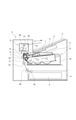
図2は、本実施例における画像形成装置の装置本体A及びカートリッジBの断面図である。ここで、装置本体Aとは、電子写真画像形成装置からカートリッジBを除いた部分である。 FIG. 2 is a cross-sectional view of the apparatus main body A and the cartridge B of the image forming apparatus in this embodiment. Here, the apparatus main body A is a portion of the electrophotographic image forming apparatus excluding the cartridge B.
図2に示す画像形成装置は、カートリッジBを装置本体Aに着脱自在とした電子写真方式を用いるレーザビームプリンタである。装置本体Aは、像担持体としての感光ドラム62に潜像を形成するための露光装置3(レーザスキャナユニット)を備える。また、カートリッジBの下側に、記録材としての紙(以下、シート材Pと記載する)を収納したシートトレイ4が配置されている。
The image forming apparatus shown in FIG. 2 is a laser beam printer using an electrophotographic method in which the cartridge B is detachably attached to and attached to the apparatus main body A. The apparatus main body A includes an exposure apparatus 3 (laser scanner unit) for forming a latent image on the
更に、装置本体Aには、シート材Pの搬送方向Dに沿って、ピックアップローラ5a、給送ローラ対5b、搬送ローラ対5c、転写ガイド6、転写ローラ7、搬送ガイド8、定着装置9、排出ローラ対10、排出トレイ11等が配置されている。定着装置9は、加熱ローラ9a及び加圧ローラ9bを備える。
Further, the apparatus main body A includes a
<カートリッジ全体の構成>
次にカートリッジBの全体構成について図2、図3、図4、図10、図11、図12、図13を用いて説明する。
<Structure of the entire cartridge>
Next, the overall configuration of the cartridge B will be described with reference to FIGS. 2, 3, 4, 10, 10, 11, 12, and 13.
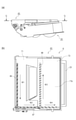
図3はカートリッジBの断面図である。図4は、第1の実施例に係るカートリッジの側面図と感光体ユニットの断面図である。図4(a)は、カートリッジBを感光ドラム62の軸線方向で見た側面図である。図4(b)は、図4(a)のQ-Qにおける感光体ユニット60の断面図である。図10、図12は、カートリッジBの構成を説明する斜視図である。図11及び図13は、図10及び図12の点線部内の箇所を、角度を変えて拡大した部分拡大図である。
FIG. 3 is a cross-sectional view of the cartridge B. FIG. 4 is a side view of the cartridge and a sectional view of the photoconductor unit according to the first embodiment. FIG. 4A is a side view of the cartridge B as viewed in the axial direction of the
本実施例において、カートリッジBは、感光体ユニット60と、現像ユニット20を有する。
In this embodiment, the cartridge B has a
図3に示すように、感光体ユニット60は、表面に静電潜像を担持する像担持体としての感光ドラム62を備える。図11、13に示すように、感光ドラム62は、駆動側に駆動側ドラムフランジ63、非駆動側に非駆動側ドラムフランジ64を含んでいる。図3に示すように、感光体ユニット60は、帯電部材としての帯電ローラ66と、感光ドラム62の表面を清掃する清掃部材としてのクリーニング部材77を備える。感光体ユニット60は、感光ドラム62、帯電ローラ66、クリーニング部材77を支持するドラム枠体71を有する。帯電ローラ66、クリーニング部材77は、それぞれ感光ドラム62の外周面に接触して配置される。
As shown in FIG. 3, the
図3、図4に示すように、クリーニング部材77によって感光ドラム62の表面から除去された除去トナーは、除去トナー搬送部材としての第1スクリュー86によってW1方向に搬送され、第2スクリュー87に受け渡される。第2スクリュー87に受け渡されたトナーは、W2方向に搬送される。W2方向に搬送されたトナーの一部は、第3スクリュー88に受け渡され、W3方向に搬送される。残りのトナーは、第2スクリュー87によって、W4方向に搬送される。そして、除去トナーはドラム枠体71に形成された除去トナー室71bに溜められる。
As shown in FIGS. 3 and 4, the removed toner removed from the surface of the
図3に示すように、現像ユニット20は、静電潜像を現像する現像剤担持体としての現像ローラ32と、現像ローラ32上のトナー層の厚みを規制するための層厚規制部材としての現像ブレード42を備える。さらに、現像ユニット20は、現像ローラ32と現像ブレード42を支持し、内部にトナーを収納する現像容器23を有する。現像ローラ32内にはマグネットローラ34が設けられている。現像ローラ32の両端には、不図示の間隔保持部材が取り付けられており、間隔保持部材と感光ドラム62が当接することで、現像ローラ32は感光ドラム62と隙間をもって保持される。
As shown in FIG. 3, the developing
現像容器23と現像底部材22によって形成されたトナー室29には、第1搬送部材43、第2搬送部材44、第3搬送部材50が設けられている。第1搬送部材43、第2搬送部材44、第3搬送部材50は、トナー室29に収容されたトナーを撹拌すると共に、現像ローラ32が備えられたトナー供給室28へトナーを搬送する。
The
図3、11に示すように、感光体ユニット60には、ドラム枠体71、蓋部材72、感光ドラム62、感光ドラム62を回転支持するためのドラム軸受73及びドラム軸78が設けられている。図13に示すように、ドラム軸受73のドラム摺動部73aにより、駆動側ドラムフランジ63が回転可能に支持される。一方、図11に示すように、ドラム枠体71に設けられたドラム軸支持穴71cに圧入されたドラム軸78が非駆動側ドラムフランジ64に挿入されることで、非駆動側ドラムフランジ64が回転可能に支持される。
As shown in FIGS. 3 and 11, the
図3、図10、図12、図13に示すように、現像ローラ32は、両端に設けられた軸受部材27、37を介して回転可能に現像容器23に取り付けられている。図13に示すように、現像ローラ32の軸32aは、軸受部材27に設けられた現像ローラ摺動部27cと摺動する。軸受部材37も、軸32aを支持する摺動面を有している(不図示)。さらに、長手方向において、軸受部材27の外側には駆動側現像サイド部材(以降、サイドカバー)26が設けられている。サイドカバー26は超音波スポット溶着で現像容器23に接合されており、詳細な説明は後述する。
As shown in FIGS. 3, 10, 12, and 13, the developing
図11、図13に示すように、感光体ユニット60と現像ユニット20を接合ピン69で互いに回動可能に接合することによってカートリッジBが構成される。
As shown in FIGS. 11 and 13, the cartridge B is configured by rotatably joining the
具体的には、現像ユニット20の長手方向両端部には、現像容器23に現像第1支持穴23a、現像第2支持穴23bが設けられている。また、感光体ユニット60の長手方向両端部には、クリーニング枠体71に第1吊り穴71i、第2吊り穴71jが設けられている。第1吊り穴71i、第2吊り穴71jに圧入固定された接合ピン69と現像第1支持穴23a、現像第2支持穴23bが嵌合することにより、感光体ユニット60と現像ユニット20は互いに回動可能に連結される。
Specifically, the developing
また、駆動側付勢部材46Rの第1穴部46Raはドラム軸受73のボス73cに掛けられ、第2穴部46Rbがサイドカバー26のボス26aに掛けられている。
Further, the first hole portion 46Ra of the drive
また非駆動側付勢部材46Fの第1穴部46Faはクリーニング枠体71のボス71kに掛けられ、第2穴部46Fbが軸受部材37のボス37aに掛けられている。
Further, the first hole portion 46Fa of the non-drive
本実施例においては駆動側付勢部材46R、非駆動側付勢部材46Fは引っ張りバネである。このバネの付勢力により現像ユニット20を感光体ユニット60に付勢させることで現像ローラ32を感光ドラム62の方向へ付勢する。そして、現像ローラ32の両端部に取り付けられた間隔保持部材38によって、現像ローラ32は感光ドラム62から所定の間隔をもって保持される。
In this embodiment, the drive
<画像形成プロセス>
次に、図2、図3を用いて、画像形成プロセスの概略を説明する。
<Image formation process>
Next, the outline of the image formation process will be described with reference to FIGS. 2 and 3.
プリントスタート信号に基づいて、感光ドラム62が矢印R方向に所定の速度で回転駆動される(図2)。
Based on the print start signal, the
電圧が印加された帯電部材(帯電ローラ)66は、感光ドラム62の外周面に接触し、感光ドラム62の外周面を帯電する。
The charging member (charging roller) 66 to which the voltage is applied comes into contact with the outer peripheral surface of the
露光装置3は、画像情報に応じたレーザ光Lを出力する。レーザ光LはカートリッジBのドラム枠体71に設けられたレーザ開口71Hを通り、感光ドラム62の外周面を露光する。これにより、感光ドラム62の外周面(表面)には画像情報に対応した静電潜像が形成される。
The
一方、図3に示すように、現像装置としての現像ユニット20において、トナー室29内のトナーTは、第1搬送部材43、第2搬送部材44、第3搬送部材50の回転によって搬送され、トナー供給室28に送り出される。トナーTは、マグネットローラ34(固定磁石)の磁力により、現像ローラ32の表面に担持される。トナーTは、現像ブレード42によって、摩擦帯電されつつ現像ローラ32の周面上での層厚が規制される。現像ローラ32の表面に担持されたトナーは、現像ローラ32の回転によって搬送される。
On the other hand, as shown in FIG. 3, in the developing
現像ローラ32には、所定の現像電圧が印可されている。トナーTは、感光ドラム62と現像ローラ32の電位差により、静電潜像に応じて感光ドラム62へ現像される。静電潜像は、トナー像として可視像化される。感光ドラム62に担持されたトナーは、感光ドラム62に回転によって搬送される。
A predetermined developing voltage is applied to the developing
ここで、装置本体Aには、カートリッジBに設けられた第1カップリング70および第2カップリング21に駆動を伝達するための第1駆動軸14および第2駆動軸19が設けられている(図8)。第1駆動軸14および第2駆動軸19は装置本体Aのモータ(不図示)により駆動される。これにより、第1カップリング70と連結している感光ドラム62が装置本体Aから駆動力を受けて回転する。また、第2カップリング21から駆動を伝達されて現像ローラ32が回転する。さらに、帯電ローラ66、現像ローラ32は、装置本体Aの給電部(不図示)より給電される。
Here, the apparatus main body A is provided with a
一方、図2に示すように、ピックアップローラ5a、給送ローラ対5b、搬送ローラ対5cによって、装置本体Aの下部に収納されたシート材Pがシートトレイ4から送り出される。そして、そのシート材Pが転写ガイド6を経由して、感光ドラム62と転写ローラ7との間の転写位置へ搬送される。この転写位置において、トナー像は感光ドラム62からシート材Pに転写される。
On the other hand, as shown in FIG. 2, the sheet material P stored in the lower part of the apparatus main body A is sent out from the seat tray 4 by the
トナー像が転写されたシート材Pは、感光ドラム62から分離されて搬送ガイド8に沿って定着装置9に搬送される。そしてシート材Pは、定着装置9を構成する加熱ローラ9aと加圧ローラ9bとのニップ部を通過し、トナー像はシート材Pに定着される。シート材Pは、排出ローラ対10まで搬送され、排出トレイ11に排出される。
The sheet material P to which the toner image is transferred is separated from the
一方、図3に示すように、転写後の感光ドラム62は、クリーニングブレード77により外周面上の残留トナーが除去されて、再び、画像形成プロセスに使用される。感光ドラム62から除去されたトナーは感光体ユニット60の除去トナー室71bに貯蔵される。
On the other hand, as shown in FIG. 3, the
上記において、帯電ローラ66、現像ローラ32、転写ローラ7、クリーニングブレード77が感光ドラム62に作用するプロセス手段である。
In the above, the charging
<カートリッジ着脱>
次に、装置本体Aに対するカートリッジBの着脱について、図5、図6、図7を用いて説明する。
<Cartridge attachment / detachment>
Next, attachment / detachment of the cartridge B to / from the apparatus main body A will be described with reference to FIGS. 5, 6, and 7.
図5は、カートリッジBを着脱するために開閉扉13を開いた装置本体Aの斜視図である。図6は、カートリッジBを着脱するために開閉扉13を開きトレイ18を引き出した状態の装置本体AとカートリッジBの斜視図である。図7は、開閉扉13を開きトレイ18を引き出した状態で、カートリッジBを着脱している際の装置本体A及びカートリッジBの斜視図である。カートリッジBは、トレイ18に対して、着脱方向Eに沿って着脱可能である。
FIG. 5 is a perspective view of the apparatus main body A in which the opening / closing
装置本体Aには開閉扉13が回動可能に取り付けられている。開閉扉13を開くとカートリッジ挿入口17が露出する。カートリッジ挿入口17内にはカートリッジBを装置本体Aに装着するためのトレイ18が備えられている。トレイ18は、所定の位置まで引き出すと、カートリッジBの着脱が可能である。カートリッジBはトレイ18に載せられた状態で図中矢印C方向にガイドレール(不図示)に沿って装置本体A内に装着される。
An opening / closing
<カートリッジ支持>
図5、図8、図9を用いて、カートリッジBの支持について説明する。
<Cartridge support>
The support of the cartridge B will be described with reference to FIGS. 5, 8 and 9.
図8は、駆動側におけるカートリッジの支持を説明する図である。図9は、非駆動側におけるカートリッジの支持を説明する図である。 FIG. 8 is a diagram illustrating support of the cartridge on the drive side. FIG. 9 is a diagram illustrating support of the cartridge on the non-driving side.
図5に示すように、装置本体AにはカートリッジBを支持するための駆動側板15と非駆動側板16が設けられている。図8、図9に示すように、駆動側板15には第1支持部15a、第2支持部15b、及びカートリッジBの回転を規制する回転規制部15cが設けられている。非駆動側板16には第1支持部16a、第2支持部16b、及びカートリッジBの回転を規制する回転規制部16cが設けられている。
As shown in FIG. 5, the apparatus main body A is provided with a
一方、カートリッジBのドラム軸受73には被支持部73b、被支持部73dが備えられる。ドラム枠体71には、駆動側に被規制部71a、非駆動側に被支持部71fと被規制部71gが設けられている。
On the other hand, the drum bearing 73 of the cartridge B is provided with a supported
被支持部73bは、第1支持部15aと当接する。被支持部73dは第2支持部15bと当接する。被規制部71aは、回転規制部15cと当接する。被支持部71fは第1支持部16aと第2支持部16bとに当接する。被規制部71gは回転規制部16cと当接する。これにより、カートリッジBは装置本体Aの内部において、装置本体Aに対するカートリッジBの位置が決められる。
The supported
<超音波スポット溶着>
本発明で用いる超音波スポット溶着での接合方法を説明する。超音波スポット溶着とは、2つの部材を、超音波を用いて接合する方法の一つである。
<Ultrasonic spot welding>
The joining method by ultrasonic spot welding used in the present invention will be described. Ultrasonic spot welding is one of the methods of joining two members by using ultrasonic waves.
超音波溶着では、超音波振動を発生する発振装置と、発振装置に取り付けられ、超音波振動を部材に伝える共鳴体が用いられる。共鳴体は、ホーンあるいは溶着ホーンと呼ばれる。溶着ホーンが部材に一定の加圧力を与え、超音波振動を与える。これにより2つ部材の樹脂の間に摩擦熱が発生する。この摩擦熱により樹脂を溶融させて接合する。 In ultrasonic welding, an oscillating device that generates ultrasonic vibration and a resonator attached to the oscillating device and transmitting the ultrasonic vibration to a member are used. The resonator is called a horn or a welded horn. The welding horn applies a constant pressure to the member and gives ultrasonic vibration. As a result, frictional heat is generated between the resins of the two members. The frictional heat melts the resin and joins it.
超音波溶着によって接合される部材の材料は、熱可塑性樹脂を含むことが望ましい。また、二つの部材の接合強度を高めるために、少なくとも溶融する部分において、二つの部材の材料は、互いに相溶性を有することが好ましい。二つの部材の材料が同じであることがより望ましい。本実施例においては、後述する第一の部材としての現像容器23と第二の部材としてのサイドカバー26の材料として、同材質のスチレン系の熱可塑性樹脂を用いた。
It is desirable that the material of the member to be joined by ultrasonic welding contains a thermoplastic resin. Further, in order to increase the bonding strength of the two members, it is preferable that the materials of the two members have compatibility with each other, at least in the melted portion. It is more desirable that the materials of the two members are the same. In this embodiment, a styrene-based thermoplastic resin of the same material was used as the material of the developing
超音波スポット溶着で用いられる溶着ホーンについて説明する。図18に示すように、溶着ホーンHは直径D1を有する円筒部Hc、円筒部Hcからホーン先端部Haに向かうに従って径が小さくなるテーパ部Hbを有する。言い換えると、溶着ホーンは、ホーン先端部Haが尖った形状を有している。このような先端形状を有する溶着ホーンを用いることにより、接合する部材に超音波を伝える突起形状(いわゆる超音波ジョイント)を形成することなく、部材同士を接合することができる。 A welding horn used in ultrasonic spot welding will be described. As shown in FIG. 18, the welded horn H has a cylindrical portion Hc having a diameter D1 and a tapered portion Hb whose diameter decreases from the cylindrical portion Hc toward the horn tip portion Ha. In other words, the welded horn has a shape in which the tip Ha of the horn is sharp. By using a welding horn having such a tip shape, the members can be joined to each other without forming a protrusion shape (so-called ultrasonic joint) that transmits ultrasonic waves to the members to be joined.
<超音波スポット溶着によるサイドカバーと現像容器の接合>
本実施例では、第一の部材としての現像容器23に対して、第二の部材としてのサイドカバー26を、超音波スポット溶着で接合する。
<Joining the side cover and developing container by ultrasonic spot welding>
In this embodiment, the
サイドカバー26の現像容器23への超音波スポット溶着による接合に関して図1、図14~図22を用いて説明する。
The bonding of the
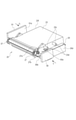
図14から図16は、サイドカバー26と現像容器23の位置決めを説明する斜視図である。図17は、超音波スポット溶着による、サイドカバー26と現像容器23の接合を説明する斜視図である。図1、図18から図22は、超音波スポット溶着による、サイドカバー26と現像容器23の接合を説明する断面図である。
14 to 16 are perspective views illustrating the positioning of the
図1、図18から図22は、後述する第1当接面23cに直交し、貯留穴部23dの中心を通る法線に沿って切断した断面を、その断面に直交する方向から見た図である。
1 and 18 to 22 are views of a cross section cut along a normal line orthogonal to the
(保持工程)
カートリッジBの生産方法は、サイドカバー26と現像容器23を、超音波スポット溶着を行う位置に保持する、保持工程を含む。以下、保持工程について説明する。
(Holding process)
The method for producing the cartridge B includes a holding step of holding the
図14、図18に示すように、現像容器23は、受け面としての第1当接面23cを有している。また、第1当接面23cには、貯留部としての貯留穴部23dが設けられている。つまり、貯留部は、第1当接面23cと交差する方向(本実施例では直交する方向)にくぼんだ凹部であり、本実施例では直径D2を有した穴である。
As shown in FIGS. 14 and 18, the developing
本実施例においては、第1当接面23cは、長手方向を向いている。言い換えると、第1当接面23cは、長手方向に交差する(本実施例では直交する)面である。
In this embodiment, the
貯留穴部23dが備えられた第1当接面23cは、現像容器23の複数の位置に設けられている。本実施例においては、貯留穴部23dが備えられた第1当接面23cの数は2つである。ただし、貯留穴部23dが備えられた第1当接面23cの数は1つでもよい。一方、現像容器23に固定された軸受部材27には、後述する基準穴27a、長穴27bが設けられている。
The
サイドカバー26には、第1当接面23cに接触する接触面としての第2当接面26cを有している。サイドカバー26と現像容器23が超音波スポット溶着される状態において、第2当接面26cは、第1当接面23cに沿って接触するように構成されている。さらに、サイドカバー26には後述する基準穴26b、長穴26eが設けられている。
The side cover 26 has a
図14に示すように、長手方向において、サイドカバー26と、サイドカバー26の組立に用いられる保持部材90とが、現像容器23の一端側に配置されている。また、長手方向において、バックアップ部材91が現像容器23の他端側に配置されている。保持部材90は、サイドカバー26の基準穴26b、長穴26eに嵌合する軸90a、90bを備える。
As shown in FIG. 14, in the longitudinal direction, the
保持部材90を図14の矢印F方向に移動させると、基準穴26b、長穴26eに軸90a、90bが嵌合する。これにより、図15に示すように、サイドカバー26は保持部材90に保持された状態となる。
When the holding
保持部材90は、サイドカバー26を保持した状態で図15の矢印F方向に移動する。これと同時に、バックアップ部材91も図15の矢印G方向に移動する。この時、図15に示すように、軸受部材27の基準穴27a、長穴27bと保持部材90の軸90a、90bが嵌合する。つまり、現像容器23が、軸受部材27を介して、保持部材90に保持された状態となる。これにより、長手方向と交差する方向において、現像容器23とサイドカバー26が位置決めされる。一方、バックアップ部材91は面91aが現像容器23の被当接面23fと当接する。
The holding
さらに、現像容器23とサイドカバー26は、第1当接面23cとサイドカバー26の第2当接面26cが当接する位置まで移動させられる。これにより、図16に示すように、現像容器23とサイドカバー26は、超音波スポット溶着が実行される位置(保持位置)に保持される。図18に示すように、現像容器23とサイドカバー26が保持位置に保持された状態において、第1当接面23cと第2当接面26cが接触している。そして、貯留穴部23dは第2当接面26cによって覆われている。本実施例では、第1当接面23cと第2当接面26cは、保持位置において平行になるように形成された平面である。第1当接面23cと第2当接面26cは、少なくとも貯留穴部23dの周囲(縁部)で当接できる平面で構成されることが好ましい。しかし、第1当接面23cと第2当接面26cが完全な平面もしくは完全に平行でなくてもよい。例えば、保持部材90によって第1当接面23cと第2当接面26cの少なくとも一方が変形して、第1当接面23cと第二当接面26が当接するように構成してもよい。
Further, the developing
このように、サイドカバー26は軸受部材27及び現像容器23に対して位置決めされ、超音波スポット溶着が行われる位置に保持される。
In this way, the
<接合工程>
カートリッジBの生産方法は、上述した保持工程によって保持位置に保持されたサイドカバー26と現像容器23を、超音波スポット溶着で接合する接合工程を含む。以下、接合工程について説明する。
<Joining process>
The method for producing the cartridge B includes a joining step of joining the
図17に示すように、長手方向において、サイドカバー26の外側には溶着ホーンHが配置されている。この溶着ホーンHは、図17の矢印H1方向(ホーン侵入方向H1)に移動する。本実施例では、溶着ホーンHは、第1当接面23cに交差する方向(好ましくは第1当接面23cの法線の方向)に沿って移動するように構成されている。溶着ホーンHのホーン先端部Haは、サイドカバー26の対向面26dと当接する。対向面26dは、第2当接面26cの反対側(裏面側)の面であり、第2当接面26cと平行な面である。つまり、溶着ホーンHは、サイドカバー26が、第1当接面23cの貯留穴部23dに向けて溶かされるように、サイドカバー26側から現像容器23側に向けて移動する。
As shown in FIG. 17, a welding horn H is arranged on the outside of the
サイドカバー26と現像容器23は、溶着箇所X、Yの2か所で接合される。溶着箇所X、Yは同じ構成であるため、以降の説明では溶着箇所Xについて説明する。また、図1、図18~図22は溶着箇所XのA-A断面図(図17参照)であり、超音波スポット溶着での接合に関わる部分のみ示した断面図である。
The
サイドカバー26の現像容器23への超音波スポット溶着での接合方法を図1、図18から図22を用いて順に説明する。
The joining method of the
図18に示したように、溶着ホーンHは直径D1を有する円筒部Hc、円筒部Hcからホーン先端部Haに向かうに従って径が小さくなるテーパ部Hbを有している。また、第2当接面26cは第1当接面23cと当接している。ここで、円筒部Hcの中心軸線Zは、ホーン先端部Haを通るように構成されている。さらに、中心軸線Zの方向は、ホーン侵入方向H1と同一である。
As shown in FIG. 18, the welded horn H has a cylindrical portion Hc having a diameter D1 and a tapered portion Hb whose diameter decreases from the cylindrical portion Hc toward the horn tip portion Ha. Further, the
ここで、中心軸線Zの方向は、第1当接面23cの法線の方向と平行である。また、中心軸線Zの方向は、第2当接面26cの法線の方向と平行である。また、中心軸線Zは、貯留穴部23dの中心を通る。言い換えると、中心軸線Zは、第1当接面23cまたは第2当接面23dに直交し、貯留穴部23dの中心を通る法線と一致する。
Here, the direction of the central axis Z is parallel to the direction of the normal line of the
ホーン先端部Haがサイドカバー26の対向面26dに当接したときの、溶着ホーンHと貯留穴部23dの位置関係について説明する。第1当接面23cの法線の方向で見たとき、ホーン先端部Haが貯留穴部23dと重なるように配置される。つまり、第1当接面23cの法線の方向(第2当接面26cの法線の方向と同じ)に直交する方向において、貯留穴部23dの位置と、ホーン先端部Haの位置は、重なっている。つまり、ホーン先端部Haは、第1当接面23cの法線方向に、貯留穴部23dを対向面26dに投影した領域内で対向面26dと当接する。言い換えると、ホーン先端部Haは、第1当接面23cに直交しホーン先端部Haを通る線が、貯留穴部23dを通るように配置される。
The positional relationship between the welded horn H and the
ここで、溶着ホーンHの円筒部Hcの直径D1と貯留穴部23dの直径D2のとの関係はD1>D2が満たされるようになっている。
Here, the relationship between the diameter D1 of the cylindrical portion Hc of the welding horn H and the diameter D2 of the
溶着ホーンHがホーン侵入方向H1に移動することで、図19に示すようにホーン先端部Haは、直径D2の貯留穴部23dを対向面26dに投影した領域内で、対向面26dと当接する。この時、溶着ホーンHは、対向面26dに対して、ホーン侵入方向H1に所定の荷重を加えている。溶着ホーンHが所定の荷重を対向面6dに加えた状態で振動することで、ホーン先端部Haと対向面26dの間に摩擦熱が発生する。この摩擦熱によって対向面26dの一部が溶融し、図20に示すように溶着ホーンHはサイドカバー26の内部に侵入する。
As the welding horn H moves in the horn intrusion direction H1, the horn tip portion Ha abuts on the facing
溶着ホーンHがサイドカバー26の内部に侵入し、超音波振動を付与することで、図21に示すように、溶着ホーンHはサイドカバー26の内部にさらに侵入する。このとき、侵入した溶着ホーンHに押し出されるように第2当接面26cに突起部26eが形成される。突起部26eは、貯留穴部23dに入り込んでいる。また、溶着ホーンHにより付与された超音波振動が、サイドカバー26を介して第2当接面26cに伝わる。これにより、第2当接面26cと第1当接面23cとの間に摩擦熱が発生し、第2当接面26cと第1当接面23cそれぞれが溶融し、溶融部が形成される。第2当接面26cと第1当接面23cの溶融部のうち、貯留穴部23dの周囲に形成されたものを、第1溶融部24と呼ぶ。
The welding horn H invades the inside of the
さらに、溶融部の一部は、貯留穴部23dの側面部23eを伝って図22の矢印J方向に流れ、貯留穴部23dに入り込む。この部分を第2溶融部25と呼ぶ。第2溶融部25は、貯留穴部23dの側面部23eと接触した状態になる。第1溶融部24と第2溶融部25はつながって一体化しているが、図22等では分けて描かれている。
Further, a part of the molten portion flows along the
その後、図1に示すように、溶着ホーンHが矢印H2方向に退避し、第1溶融部24及び第2溶融部25が冷却されて固化する。これにより、サイドカバー26と現像容器23は固化した第1溶融部24及び第2溶融部25と共に一体化して接合された状態となる。
After that, as shown in FIG. 1, the welding horn H retracts in the direction of the arrow H2, and the
以上で、サイドカバー26の現像容器23への超音波スポット溶着による接合が完了する。
This completes the bonding of the
なお、上記の説明では保持部材90とバックアップ部材91の移動と、溶着ホーンHの移動を別のタイミングで行った例を示したが、これらが同時になされるものでもよい。その場合、溶着ホーンHがサイドカバー26に当接する前に、第1当接面23cと第2当接面26cが当接していればよい。
In the above description, an example in which the holding
サイドカバー26と現像容器23が接合された状態では、第1当接面23cの貯留穴部23dを、第2当接面26cが覆っている。そして、第1当接面23cと第2当接面26cが接触している。サイドカバー26には、貯留穴部23dに向かってくぼむ凹部26fが形成されている。そして、溶融部の少なくとも一部(第2溶融部25)が、貯留穴部23dに入り込んだ状態となっている。つまり、サイドカバー26と現像容器23の長手位置を決めている第2当接面26cと第1当接面23cとの間に溶融部が入り込む量を減らし、第1当接面23cと第2当接面26cが離れることを低減できる。また、サイドカバー26と現像容器23が第1溶融部24だけでなく第2溶融部25でも接合されているため、接合面積が増え、接合強度を上げることもできる。つまり、図1に示したように、サイドカバー26と現像容器23の剥離方向であるH3方向と、H3方向に対して交差する方向に、第1溶融部24と第2溶融部25が形成されている。このため、サイドカバー26の現像容器23に対する剥離強度を上げることもできる。
In the state where the
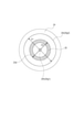
ここで、図1、図23を用いて、凹部26fについて説明する。図23は、凹部26fを、第1当接面23cの法線方向から見た図である。図23は、第1当接面23cの法線方向に沿って、サイドカバー26の側から見た図を示している。
Here, the
図1に示すように、凹部26fは、溶着ホーンHの形状が転写された形状をしている。つまり、凹部26fにはテーパ部Hbによって形成された傾斜部26gを有している。凹部26fには、ホーン先端部Haによって形成された凹部先端部26hが形成されている。凹部26fには、円筒部Hcによって形成された円筒形状部26iが形成されている。
As shown in FIG. 1, the
傾斜部26gは、第1当接面23cの法線に対して交差する方向に延びる。ここで、凹部の中央側に位置する傾斜部26gの端部を第一の端部26g1とし、反対側の端部を第二の端部26g2と呼ぶ。第一の端部26g1は、凹部先端部26hと接続されている。第二の端部26g2は、円筒形状部26iと接続されている。このとき、図23に示すように、第1当接面23cの法線方向で見たときに、第一の端部26g1は、貯留穴部23dの内側に位置している。そして、第二の端部26g2は貯留穴部23dの外側に位置している。さらに、第二の端部26g2の外側に、第1溶融部24の端部が位置している。一方、図1に示すように、凹部26fは第1当接面23cに達しない深さで設けられる。つまり、凹部26fは第1当接面23cに対して、貯留穴部23dの反対側に位置する。
The
凹部26fがこのような形状を有するように、溶着ホーンHによってサイドカバー26と現像容器23を超音波スポット溶着で接合することで、溶融部の一部(第2溶融部25)が、貯留穴部23dに入り込みやすくなる。また、貯留穴部23dの周囲全体に第1溶融部24が形成されやすくなり、サイドカバー26と現像容器23の接合強度を向上できる。
By joining the
尚、ここまでの説明ではサイドカバー26と軸受部材27を別体の構成として説明してきたが、一体の構成にも適用しうる。
Although the
また、本実施例では、現像ユニット20に設けられたサイドカバー26と現像容器23の接合方法を説明した。しかし、本発明はこれに限定されず、他の部品同士の接合にも使用できる。例えば、感光体ユニット60に設けられたドラム軸受73とドラム枠体71の接合にも適用できる。また、軸受部材27と現像容器23の接合にも適用できる。
Further, in this embodiment, a method of joining the
また、本発明のカートリッジは装置本体に着脱可能であったが、装置本体に固定されるものであってもよい。 Further, although the cartridge of the present invention was removable from the device main body, it may be fixed to the device main body.
また、カートリッジBは感光ドラム62や現像ローラ32などの回転部材を有している。そして、これらに当接して回転可能に支持する、ドラム摺動部73aや現像ローラ摺動部27c等の摺動部を有している。本実施例では、摺動部に対して溶融部が離れた位置に形成されるようにした。こうすることで、摺動部が溶かされることによって、これら回転部材の回転が不安定になることを防ぐことができる。感光ドラム62や現像ローラ32を除いた回転部材との摺動部においても、溶融部を離して形成することで、その回転部材の回転を安定させることができる。
Further, the cartridge B has a rotating member such as a
また、カートリッジBは、装置本体に対してカートリッジBの位置を決めるための位置決め部を備えている(被支持部73b、被支持部73d、被規制部71a、被支持部71f、被規制部71g)。本実施例では、これらに対して溶融部が離れた位置に形成されるようにした。こうすることで、位置決め部が溶かされることによって、これらカートリッジの位置決めが不安定になることを防ぐことができる。
Further, the cartridge B includes a positioning portion for determining the position of the cartridge B with respect to the main body of the apparatus (supported
超音波スポット溶着は装置の汎用性も高いうえに、ビスなどの部品を省略できる。したがって、部品コストや組み立て装置のコストも削減できる。また、接着剤を使用する場合と比較して、接合にかかる時間が短い。 Ultrasonic spot welding has high versatility of the device, and parts such as screws can be omitted. Therefore, the cost of parts and the cost of assembly equipment can be reduced. In addition, the time required for joining is shorter than when an adhesive is used.
さらに本構成を用いることで、2つの部品(サイドカバー26と現像容器23)の超音波スポット溶着で接合するときに、位置決め精度の維持と強固な固定を両立しながら、これらを省スペースで実現することができる。
Furthermore, by using this configuration, when joining two parts (
20 現像ユニット
22 現像底部材
23 現像容器
23c 第1当接面
23d 貯留穴部
24 第1溶融部
25 第2溶融部
26 サイドカバー
26c 第2当接面
26d 対向面
26f 凹部
26g 傾斜部
26g1 第一の端部
26g2 第二の端部
32 現像ローラ(現像剤担持体)
60 感光体ユニット
62 感光ドラム
71 ドラム枠体
71c ドラム軸支持穴
73 ドラム軸受
73a ドラム摺動部
A 画像形成装置本体(装置本体)
B プロセスカートリッジ(カートリッジ)
H 溶着ホーン
Ha ホーン先端部
Hb テーパ部
Hc 円筒部
D1 円筒部の直径
D2 貯留穴部の直径
20
60
B process cartridge (cartridge)
H Welding horn Ha Horn tip Hb Taper part Hc Cylindrical part D1 Cylindrical part diameter D2 Storage hole diameter
Claims (16)
前記生産方法は、
前記第二の面が前記穴を覆い、前記第二の面と前記第一の面が接触するように、前記第一の部材と前記第二の部材を保持する保持工程と、
前記第一の部材と前記第二の部材を接合する接合工程であって、前記第三の面が溶かされ前記第二の部材に前記穴に向かってくぼむ凹部が前記第三の面に形成され、かつ前記第一の部材と前記第二の部材の溶融部の少なくとも一部が前記穴に入り込むように、前記第一の部材と前記第二の部材を超音波スポット溶着で接合する接合工程と、
を含むことを特徴とする生産方法。 A method of producing a cartridge to be attached to the main body of an image forming apparatus, wherein the cartridge is formed on a first surface, a first member having holes provided on the first surface, and the first surface . It comprises a second surface that comes into contact with, and a second member having a third surface opposite the second surface .
The production method is
A holding step of holding the first member and the second member so that the second surface covers the hole and the second surface and the first surface come into contact with each other.
In the joining step of joining the first member and the second member, the third surface is melted and a recess recessed toward the hole is formed in the second member on the third surface. A joining step of joining the first member and the second member by ultrasonic spot welding so that at least a part of the molten portion of the first member and the second member enters the hole . When,
A production method characterized by including.
前記法線の方向から見たときに、前記第一の端部は前記穴の内側に位置することを特徴とする請求項1に記載の生産方法。 The recess has an inclined portion extending in a direction intersecting the normal of the first surface , and the inclined portion has a first end portion located on the center side of the recess and the first one. Has a second end located on the opposite side of the end,
The production method according to claim 1, wherein the first end portion is located inside the hole when viewed from the direction of the normal line.
前記溶融部は前記摺動部から離れた位置に形成されることを特徴とする請求項1から4のいずれか一項に記載の生産方法。 The cartridge has a rotating member and a sliding portion that abuts on the rotating member and rotatably supports the rotating member.
The production method according to any one of claims 1 to 4, wherein the molten portion is formed at a position away from the sliding portion.
前記溶融部は前記位置決め部から離れた位置に形成されることを特徴とする請求項1から7のいずれか一項に記載の生産方法。 The cartridge has a positioning unit for positioning the cartridge with respect to the apparatus main body.
The production method according to any one of claims 1 to 7, wherein the molten portion is formed at a position away from the positioning portion.
第一の面と穴を有する第一の部材と、
前記第一の面に接触する第二の面、および前記第二の面の反対側の第三の面を有する第二の部材であって、前記第二の面が前記穴を覆い、前記第二の面と前記第一の面が接触するように配置された第二の部材と、
を備え、
前記第一の部材と前記第二の部材は、前記第三の面に前記穴に向かってくぼむ凹部が形成され、かつ前記第一の部材と前記第二の部材の溶融部の少なくとも一部が、前記穴に入り込むように接合されていることを特徴とするカートリッジ。 A cartridge that can be attached to the main body of an image forming device.
A first member with a first surface and a hole ,
A second member having a second surface in contact with the first surface and a third surface opposite the second surface , wherein the second surface covers the hole and the first surface . A second member arranged so that the second surface and the first surface are in contact with each other,
Equipped with
The first member and the second member have a recess formed in the third surface toward the hole , and at least a part of a molten portion of the first member and the second member. Is a cartridge characterized in that it is joined so as to enter the hole .
前記法線の方向から見たときに、前記第一の端部は前記穴の内側に位置することを特徴とする請求項9に記載のカートリッジ。 The recess has an inclined portion extending in a direction intersecting the normal of the first surface , and the inclined portion has a first end portion located on the center side of the recess and the first one. Has a second end located on the opposite side of the end,
The cartridge according to claim 9, wherein the first end is located inside the hole when viewed from the direction of the normal.
前記溶融部は前記摺動部から離れた位置に形成されることを特徴とする請求項9から12のいずれか一項に記載のカートリッジ。 The cartridge has a rotating member and a sliding portion that abuts on the rotating member and rotatably supports the rotating member.
The cartridge according to any one of claims 9 to 12, wherein the molten portion is formed at a position away from the sliding portion.
前記溶融部は前記位置決め部から離れた位置に形成されることを特徴とする請求項9から15のいずれか一項に記載のカートリッジ。 The cartridge has a positioning unit for positioning the cartridge with respect to the apparatus main body.
The cartridge according to any one of claims 9 to 15, wherein the molten portion is formed at a position away from the positioning portion.
Priority Applications (5)
| Application Number | Priority Date | Filing Date | Title |
|---|---|---|---|
| JP2017252541A JP7005342B2 (en) | 2017-12-27 | 2017-12-27 | Cartridge production method and cartridge |
| EP18208135.6A EP3506024B1 (en) | 2017-12-27 | 2018-11-23 | Cartridge and manufacturing method of cartridge |
| KR1020180148870A KR102315043B1 (en) | 2017-12-27 | 2018-11-27 | Manufacturing method of cartridge and cartridge |
| CN201811420729.9A CN109976126B (en) | 2017-12-27 | 2018-11-27 | Method for manufacturing cartridge and cartridge |
| US16/209,747 US10545431B2 (en) | 2017-12-27 | 2018-12-04 | Manufacturing method of cartridge and cartridge |
Applications Claiming Priority (1)
| Application Number | Priority Date | Filing Date | Title |
|---|---|---|---|
| JP2017252541A JP7005342B2 (en) | 2017-12-27 | 2017-12-27 | Cartridge production method and cartridge |
Publications (3)
| Publication Number | Publication Date |
|---|---|
| JP2019117355A JP2019117355A (en) | 2019-07-18 |
| JP2019117355A5 JP2019117355A5 (en) | 2021-02-12 |
| JP7005342B2 true JP7005342B2 (en) | 2022-01-21 |
Family
ID=64456890
Family Applications (1)
| Application Number | Title | Priority Date | Filing Date |
|---|---|---|---|
| JP2017252541A Active JP7005342B2 (en) | 2017-12-27 | 2017-12-27 | Cartridge production method and cartridge |
Country Status (5)
| Country | Link |
|---|---|
| US (1) | US10545431B2 (en) |
| EP (1) | EP3506024B1 (en) |
| JP (1) | JP7005342B2 (en) |
| KR (1) | KR102315043B1 (en) |
| CN (1) | CN109976126B (en) |
Families Citing this family (3)
| Publication number | Priority date | Publication date | Assignee | Title |
|---|---|---|---|---|
| JP7179476B2 (en) * | 2018-04-05 | 2022-11-29 | キヤノン株式会社 | Method for manufacturing support unit, method for manufacturing developer container, method for manufacturing photoreceptor unit, and method for manufacturing process cartridge |
| KR20240136104A (en) | 2023-03-06 | 2024-09-13 | 주식회사 엠디케이 | Apparatus for fusing ink film of photo printer cartridge assembling equipment |
| KR20240136105A (en) | 2023-03-06 | 2024-09-13 | 주식회사 엠디케이 | Apparatus for installing photographic paper of photo printer cartridge assembling equipment |
Citations (7)
| Publication number | Priority date | Publication date | Assignee | Title |
|---|---|---|---|---|
| JP2000326413A (en) | 1999-05-20 | 2000-11-28 | Meiwa Ind Co Ltd | Method for ultrasonic fusion bonding |
| JP2002040781A (en) | 2000-07-28 | 2002-02-06 | Canon Inc | Electrophotographic image forming device, process cartridge, developing device and frame body welding method |
| JP2003241622A (en) | 2001-12-13 | 2003-08-29 | Canon Inc | Process cartridge and electrophotographic image forming device |
| JP2005246941A (en) | 2004-02-03 | 2005-09-15 | Nhk Spring Co Ltd | Ultrasonic welding structure and ultrasonic welding method |
| US20080181659A1 (en) | 2007-01-31 | 2008-07-31 | Samsung Electronics Co., Ltd. | Developing cartridge and image forming apparatus including the same |
| JP2013148875A (en) | 2011-12-21 | 2013-08-01 | Canon Inc | Developing container, method for manufacturing the same and developing device and image formation device using the same |
| JP2014215479A (en) | 2013-04-25 | 2014-11-17 | キヤノン株式会社 | Developer container, developing device, cleaning device, process cartridge, and image forming apparatus |
Family Cites Families (11)
| Publication number | Priority date | Publication date | Assignee | Title |
|---|---|---|---|---|
| JPH0224978Y2 (en) * | 1984-11-02 | 1990-07-10 | ||
| JP3214114B2 (en) * | 1992-10-29 | 2001-10-02 | 豊田合成株式会社 | Ultrasonic welding method |
| JPH09271862A (en) * | 1996-04-05 | 1997-10-21 | Showa Alum Corp | Dissimilar metal joining member and its production |
| JPH11268135A (en) | 1998-03-19 | 1999-10-05 | Sekisui Chem Co Ltd | Ultrasonic joining method |
| JP2001277363A (en) * | 2000-03-29 | 2001-10-09 | Fujitsu Ten Ltd | Method for welding resin member |
| JP3970161B2 (en) * | 2002-11-08 | 2007-09-05 | キヤノン株式会社 | Process cartridge remanufacturing method |
| JP2005049762A (en) | 2003-07-31 | 2005-02-24 | Canon Inc | Process cartridge and drum support member |
| JP6057651B2 (en) * | 2012-10-01 | 2017-01-11 | キヤノン株式会社 | Process cartridge and process cartridge manufacturing method |
| JP2014115472A (en) * | 2012-12-10 | 2014-06-26 | Canon Inc | Cartridge and manufacturing method for cartridge |
| CN104678735A (en) * | 2013-12-02 | 2015-06-03 | 珠海赛纳打印科技股份有限公司 | Repairing method of process cartridge and process cartridge obtained by repair |
| US9535398B2 (en) * | 2014-09-04 | 2017-01-03 | Canon Kabushiki Kaisha | Developer cartridge, developing apparatus, process cartridge and image forming apparatus |
-
2017
- 2017-12-27 JP JP2017252541A patent/JP7005342B2/en active Active
-
2018
- 2018-11-23 EP EP18208135.6A patent/EP3506024B1/en active Active
- 2018-11-27 KR KR1020180148870A patent/KR102315043B1/en active IP Right Grant
- 2018-11-27 CN CN201811420729.9A patent/CN109976126B/en active Active
- 2018-12-04 US US16/209,747 patent/US10545431B2/en active Active
Patent Citations (7)
| Publication number | Priority date | Publication date | Assignee | Title |
|---|---|---|---|---|
| JP2000326413A (en) | 1999-05-20 | 2000-11-28 | Meiwa Ind Co Ltd | Method for ultrasonic fusion bonding |
| JP2002040781A (en) | 2000-07-28 | 2002-02-06 | Canon Inc | Electrophotographic image forming device, process cartridge, developing device and frame body welding method |
| JP2003241622A (en) | 2001-12-13 | 2003-08-29 | Canon Inc | Process cartridge and electrophotographic image forming device |
| JP2005246941A (en) | 2004-02-03 | 2005-09-15 | Nhk Spring Co Ltd | Ultrasonic welding structure and ultrasonic welding method |
| US20080181659A1 (en) | 2007-01-31 | 2008-07-31 | Samsung Electronics Co., Ltd. | Developing cartridge and image forming apparatus including the same |
| JP2013148875A (en) | 2011-12-21 | 2013-08-01 | Canon Inc | Developing container, method for manufacturing the same and developing device and image formation device using the same |
| JP2014215479A (en) | 2013-04-25 | 2014-11-17 | キヤノン株式会社 | Developer container, developing device, cleaning device, process cartridge, and image forming apparatus |
Also Published As
| Publication number | Publication date |
|---|---|
| KR102315043B1 (en) | 2021-10-19 |
| EP3506024A1 (en) | 2019-07-03 |
| EP3506024B1 (en) | 2021-09-29 |
| CN109976126B (en) | 2022-03-29 |
| US20190196358A1 (en) | 2019-06-27 |
| CN109976126A (en) | 2019-07-05 |
| KR20190079504A (en) | 2019-07-05 |
| US10545431B2 (en) | 2020-01-28 |
| JP2019117355A (en) | 2019-07-18 |
Similar Documents
| Publication | Publication Date | Title |
|---|---|---|
| JP6140962B2 (en) | Cartridge, process cartridge, and image forming apparatus | |
| US7127192B2 (en) | Developing frame and process cartridge | |
| JP7005342B2 (en) | Cartridge production method and cartridge | |
| JP6120663B2 (en) | Developer container, developing device, cleaning device, process cartridge, and image forming apparatus | |
| JP5489883B2 (en) | cartridge | |
| JP2017076035A (en) | cartridge | |
| US9535398B2 (en) | Developer cartridge, developing apparatus, process cartridge and image forming apparatus | |
| KR102415339B1 (en) | Supporting unit, developer container, developing device, photosensitive member unit, process cartridge and manufacturing method of the supporting unit | |
| JP6808311B2 (en) | Electrophotographic photosensitive drum unit, cartridge, and flange member | |
| JP2003062911A (en) | Method for manufacturing hollow body made of synthetic resin, connecting structure, toner supply container, process cartridge and electrophotographic image forming apparatus | |
| JP7277164B2 (en) | Method for manufacturing frame unit, method for manufacturing image carrying unit, method for manufacturing cartridge, and cartridge | |
| JP7102187B2 (en) | Cartridge manufacturing method | |
| JP2017067882A (en) | Developer container, developing device, process cartridge, image forming apparatus, and manufacturing method of developer container | |
| JP2019191512A (en) | Image forming apparatus | |
| JP6033171B2 (en) | Developing device, cleaning device, process cartridge, and image forming apparatus | |
| JP2009226603A (en) | Welding rib and developer storage member | |
| JP2019128550A (en) | Method for reproducing cartridge | |
| JP6896376B2 (en) | Cartridge and image forming device | |
| JP2016057611A (en) | Developer container, developing device, process cartridge, and image forming apparatus | |
| JP2021196495A (en) | Developer storage container, developing device, and cartridge | |
| JP2014219431A (en) | Developer container, developing device using the same, cleaning device, process cartridge, image forming apparatus, and manufacturing method of developing container | |
| JP2007057960A (en) | Process cartridge, developing device, and electrophotographic image forming apparatus |
Legal Events
| Date | Code | Title | Description |
|---|---|---|---|
| A521 | Request for written amendment filed |
Free format text: JAPANESE INTERMEDIATE CODE: A523 Effective date: 20201223 |
|
| A621 | Written request for application examination |
Free format text: JAPANESE INTERMEDIATE CODE: A621 Effective date: 20201223 |
|
| A977 | Report on retrieval |
Free format text: JAPANESE INTERMEDIATE CODE: A971007 Effective date: 20211125 |
|
| TRDD | Decision of grant or rejection written | ||
| A01 | Written decision to grant a patent or to grant a registration (utility model) |
Free format text: JAPANESE INTERMEDIATE CODE: A01 Effective date: 20211207 |
|
| A61 | First payment of annual fees (during grant procedure) |
Free format text: JAPANESE INTERMEDIATE CODE: A61 Effective date: 20220105 |