JP6896376B2 - Cartridge and image forming device - Google Patents
Cartridge and image forming device Download PDFInfo
- Publication number
- JP6896376B2 JP6896376B2 JP2016091441A JP2016091441A JP6896376B2 JP 6896376 B2 JP6896376 B2 JP 6896376B2 JP 2016091441 A JP2016091441 A JP 2016091441A JP 2016091441 A JP2016091441 A JP 2016091441A JP 6896376 B2 JP6896376 B2 JP 6896376B2
- Authority
- JP
- Japan
- Prior art keywords
- cartridge
- rotation axis
- distance
- main body
- image forming
- Prior art date
- Legal status (The legal status is an assumption and is not a legal conclusion. Google has not performed a legal analysis and makes no representation as to the accuracy of the status listed.)
- Active
Links
Images


Classifications
-
- G—PHYSICS
- G03—PHOTOGRAPHY; CINEMATOGRAPHY; ANALOGOUS TECHNIQUES USING WAVES OTHER THAN OPTICAL WAVES; ELECTROGRAPHY; HOLOGRAPHY
- G03G—ELECTROGRAPHY; ELECTROPHOTOGRAPHY; MAGNETOGRAPHY
- G03G21/00—Arrangements not provided for by groups G03G13/00 - G03G19/00, e.g. cleaning, elimination of residual charge
- G03G21/16—Mechanical means for facilitating the maintenance of the apparatus, e.g. modular arrangements
- G03G21/18—Mechanical means for facilitating the maintenance of the apparatus, e.g. modular arrangements using a processing cartridge, whereby the process cartridge comprises at least two image processing means in a single unit
- G03G21/1803—Arrangements or disposition of the complete process cartridge or parts thereof
-
- G—PHYSICS
- G03—PHOTOGRAPHY; CINEMATOGRAPHY; ANALOGOUS TECHNIQUES USING WAVES OTHER THAN OPTICAL WAVES; ELECTROGRAPHY; HOLOGRAPHY
- G03G—ELECTROGRAPHY; ELECTROPHOTOGRAPHY; MAGNETOGRAPHY
- G03G21/00—Arrangements not provided for by groups G03G13/00 - G03G19/00, e.g. cleaning, elimination of residual charge
- G03G21/16—Mechanical means for facilitating the maintenance of the apparatus, e.g. modular arrangements
- G03G21/18—Mechanical means for facilitating the maintenance of the apparatus, e.g. modular arrangements using a processing cartridge, whereby the process cartridge comprises at least two image processing means in a single unit
- G03G21/1839—Means for handling the process cartridge in the apparatus body
- G03G21/1857—Means for handling the process cartridge in the apparatus body for transmitting mechanical drive power to the process cartridge, drive mechanisms, gears, couplings, braking mechanisms
- G03G21/1864—Means for handling the process cartridge in the apparatus body for transmitting mechanical drive power to the process cartridge, drive mechanisms, gears, couplings, braking mechanisms associated with a positioning function
-
- G—PHYSICS
- G03—PHOTOGRAPHY; CINEMATOGRAPHY; ANALOGOUS TECHNIQUES USING WAVES OTHER THAN OPTICAL WAVES; ELECTROGRAPHY; HOLOGRAPHY
- G03G—ELECTROGRAPHY; ELECTROPHOTOGRAPHY; MAGNETOGRAPHY
- G03G21/00—Arrangements not provided for by groups G03G13/00 - G03G19/00, e.g. cleaning, elimination of residual charge
- G03G21/16—Mechanical means for facilitating the maintenance of the apparatus, e.g. modular arrangements
- G03G21/18—Mechanical means for facilitating the maintenance of the apparatus, e.g. modular arrangements using a processing cartridge, whereby the process cartridge comprises at least two image processing means in a single unit
- G03G21/1803—Arrangements or disposition of the complete process cartridge or parts thereof
- G03G21/1814—Details of parts of process cartridge, e.g. for charging, transfer, cleaning, developing
-
- G—PHYSICS
- G03—PHOTOGRAPHY; CINEMATOGRAPHY; ANALOGOUS TECHNIQUES USING WAVES OTHER THAN OPTICAL WAVES; ELECTROGRAPHY; HOLOGRAPHY
- G03G—ELECTROGRAPHY; ELECTROPHOTOGRAPHY; MAGNETOGRAPHY
- G03G21/00—Arrangements not provided for by groups G03G13/00 - G03G19/00, e.g. cleaning, elimination of residual charge
- G03G21/16—Mechanical means for facilitating the maintenance of the apparatus, e.g. modular arrangements
- G03G21/18—Mechanical means for facilitating the maintenance of the apparatus, e.g. modular arrangements using a processing cartridge, whereby the process cartridge comprises at least two image processing means in a single unit
- G03G21/1839—Means for handling the process cartridge in the apparatus body
- G03G21/1842—Means for handling the process cartridge in the apparatus body for guiding and mounting the process cartridge, positioning, alignment, locks
- G03G21/185—Means for handling the process cartridge in the apparatus body for guiding and mounting the process cartridge, positioning, alignment, locks the process cartridge being mounted parallel to the axis of the photosensitive member
-
- G—PHYSICS
- G03—PHOTOGRAPHY; CINEMATOGRAPHY; ANALOGOUS TECHNIQUES USING WAVES OTHER THAN OPTICAL WAVES; ELECTROGRAPHY; HOLOGRAPHY
- G03G—ELECTROGRAPHY; ELECTROPHOTOGRAPHY; MAGNETOGRAPHY
- G03G2221/00—Processes not provided for by group G03G2215/00, e.g. cleaning or residual charge elimination
- G03G2221/16—Mechanical means for facilitating the maintenance of the apparatus, e.g. modular arrangements and complete machine concepts
- G03G2221/1651—Mechanical means for facilitating the maintenance of the apparatus, e.g. modular arrangements and complete machine concepts for connecting the different parts
- G03G2221/1654—Locks and means for positioning or alignment
Landscapes
- Engineering & Computer Science (AREA)
- Computer Vision & Pattern Recognition (AREA)
- Physics & Mathematics (AREA)
- General Physics & Mathematics (AREA)
- Electrophotography Configuration And Component (AREA)
Description
本発明は、プロセスカートリッジ及びこれを用いた画像形成装置に関するものである。ここでプロセスカートリッジとは、電子写真感光体と、この電子写真感光体に作用するプロセス手段とを一体的にカートリッジ化して、電子写真画像形成装置の装置本体に対して取り外し可能に装着されるものである。例えば、電子写真感光体と、プロセス手段としての、現像手段、帯電手段、クリーニング手段の少なくとも一つを一体的にカートリッジ化したプロセスカートリッジが挙げられる。 The present invention relates to a process cartridge and an image forming apparatus using the process cartridge. Here, the process cartridge is a cartridge in which the electrophotographic photosensitive member and the process means acting on the electrophotographic photosensitive member are integrally formed into a cartridge and detachably attached to the main body of the electrophotographic image forming apparatus. Is. For example, a process cartridge in which at least one of a developing means, a charging means, and a cleaning means as a process means is integrally formed into a cartridge may be mentioned.
また、電子写真画像形成装置とは電子写真画像形成方式を用いて記録媒体に画像を形成するものである。電子写真画像形成装置の例としては、例えば、電子写真複写機、電子写真プリンタ(LEDプリンタ、レーザビームプリンタ等)、ファクシミリ装置及びワードプロセッサ等が含まれる。 Further, the electrophotographic image forming apparatus is an device that forms an image on a recording medium by using an electrophotographic image forming method. Examples of the electrophotographic image forming apparatus include, for example, an electrophotographic copying machine, an electrophotographic printer (LED printer, laser beam printer, etc.), a facsimile machine, a word processor, and the like.
電子写真画像形成装置(以下、画像形成装置)では、像担持体としての一般にドラム型とされる電子写真感光体(以下、感光体ドラム)を一様に帯電させる。次いで、帯電した感光体ドラムを選択的な露光することによって、感光体ドラム上に静電潜像(静電像)を形成する。次いで、感光体ドラム上に形成された静電潜像を、現像剤としてのトナーでトナー像として現像する。そして、感光体ドラム上に形成されたトナー像を、記録用紙、プラスチックシートなどの記録材に転写し、更に記録材上に転写されたトナー像に熱や圧力を加えることでトナー像を記録材に定着させることで画像記録を行う。 In the electrophotographic image forming apparatus (hereinafter, image forming apparatus), an electrophotographic photosensitive member (hereinafter, a photoconductor drum), which is generally a drum type as an image carrier, is uniformly charged. Next, an electrostatic latent image (electrostatic image) is formed on the photoconductor drum by selectively exposing the charged photoconductor drum. Next, the electrostatic latent image formed on the photoconductor drum is developed as a toner image with toner as a developer. Then, the toner image formed on the photoconductor drum is transferred to a recording material such as recording paper or a plastic sheet, and heat or pressure is applied to the toner image transferred on the recording material to record the toner image. Image recording is performed by fixing to.
このような画像形成装置は、一般に、トナー補給や各種のプロセス手段のメンテナンスを必要とする。このトナー補給やメンテナンスを容易にするため、感光体ドラム、帯電手段、現像手段、クリーニング手段などをまとめてカートリッジ化し、画像形成装置の装置本体に着脱可能なプロセスカートリッジ(以下、カートリッジ)としたものが実用化されている。 Such an image forming apparatus generally requires toner replenishment and maintenance of various process means. In order to facilitate this toner replenishment and maintenance, the photoconductor drum, charging means, developing means, cleaning means, etc. are collectively made into a cartridge, which is a process cartridge (hereinafter referred to as a cartridge) that can be attached to and detached from the main body of the image forming apparatus. Has been put into practical use.
このプロセスカートリッジ方式によれば、装置のメンテナンスをユーザ自身で行うことができるので、格段に操作性を向上させることができ、ユーザビリティーに優れた画像形成装置を提供することができる。そのため、このプロセスカートリッジ方式は画像形成装置において広く用いられている。 According to this process cartridge method, since the maintenance of the device can be performed by the user himself / herself, the operability can be remarkably improved, and the image forming device having excellent usability can be provided. Therefore, this process cartridge method is widely used in an image forming apparatus.
上述のように、カートリッジはユーザ自身が画像形成装置に着脱するため、カートリッジの着脱の際にはカートリッジを傷つけることなく、簡単に交換できる構成とすることが望まれる。 As described above, since the cartridge is attached to and detached from the image forming apparatus by the user, it is desired that the cartridge can be easily replaced without damaging the cartridge.
特許文献1では、カートリッジを画像形成装置に装着したのち、画像形成装置内の部品を移動させることでカートリッジを画像形成装置に位置決めする構成が提案されている。
しかしながら、画像形成装置の内部に部品を配置し、カートリッジを移動させ、位置決めする構成では、部品点数が増えて、その分のコストが掛かる上、構成が複雑となり、組み立てが煩雑、また画像形成装置が大型化する、といった課題があった。 However, in the configuration in which the parts are arranged inside the image forming apparatus, the cartridge is moved, and the cartridge is positioned, the number of parts is increased, the cost is increased accordingly, the configuration is complicated, the assembly is complicated, and the image forming apparatus is complicated. There was a problem that the size of the image increased.
そこで、簡易な構成でカートリッジを支持可能とし、製造コストの低減や簡易な組立、または画像形成装置の本体の小型化を可能とするカートリッジ及び画像形成装置を提供することを目的とする。 Therefore, it is an object of the present invention to provide a cartridge and an image forming apparatus capable of supporting a cartridge with a simple configuration, reducing a manufacturing cost, simple assembling, or downsizing the main body of the image forming apparatus.
上記目的を達成するため、本発明に係るカートリッジは、感光ドラムと、前記感光ドラムに作用するように構成されたプロセス手段と、回転軸線を中心に回転可能になるように前記感光ドラムを支持し、前記プロセス手段を支持する枠体と、を有し、画像形成装置の装置本体に対して前記回転軸線の方向に沿う方向である装着方向に着脱できるように構成されたカートリッジにおいて、前記枠体は、前記装着方向の下流側の前記枠体の端部に設けられた第1被位置決め部であって、前記装置本体に当接して前記装着方向に直交する方向の前記装置本体に対する前記カートリッジの位置を決めるための第1被位置決め部と、
前記装着方向の上流側の前記枠体の端部に設けられた第2被位置決め部であって、前記装置本体に当接して前記直交する方向の前記カートリッジの位置を決めるための第2被位置決め部と、を有し、前記装着方向に見たときに、前記回転軸線から離れる方向である所定方向における前記回転軸線から第1被位置決め部までの距離よりも、前記所定方向における前記回転軸線から前記第2被位置決め部までの距離の方が長く、前記第2被位置決め部は、前記装着方向に見たときに、前記所定方向へ突出した第1突出部と、前記所定方向と交差する方向であって前記回転軸線から離れる方向へ突出した第2突出部と、を含み、前記感光ドラムの回転方向において前記第1突出部と前記第2突出部との間には隙間が設けられていることを特徴とする。
In order to achieve the above object, the cartridge according to the present invention supports a photosensitive drum, a process means configured to act on the photosensitive drum, and the photosensitive drum so as to be rotatable about a rotation axis. In a cartridge having a frame body that supports the process means and is configured to be detachable in a mounting direction that is a direction along the direction of the rotation axis with respect to the device main body of the image forming apparatus, the frame body. Is a first positioned portion provided at the end of the frame body on the downstream side in the mounting direction, and the cartridge of the cartridge with respect to the device main body in a direction orthogonal to the mounting direction in contact with the device main body. The first positioned part for determining the position and
A second positioned portion provided at the end of the frame on the upstream side in the mounting direction, which is a second positioned portion for abutting the main body of the device and determining the position of the cartridge in the orthogonal direction. From the rotation axis in the predetermined direction, rather than the distance from the rotation axis to the first positioned portion in a predetermined direction, which is a direction away from the rotation axis when viewed in the mounting direction. the second rather long direction of the distance to the positioning portion, the second portion to be positioned, when viewed in the mounting direction, a first protrusion protruding to the predetermined direction, intersecting with the predetermined direction A gap is provided between the first protrusion and the second protrusion in the direction of rotation of the photosensitive drum, including a second protrusion that protrudes in the direction away from the rotation axis. and said that you are.
また、本発明に係る画像形成装置は、感光ドラムと、前記感光ドラムに作用するプロセス手段と、回転軸線を中心に回転可能になるように前記感光ドラムを支持し、前記プロセス手段を支持する枠体と、を有するカートリッジと、前記カートリッジが前記回転軸線に沿った装着方向に着脱可能な装置本体であって、第1側板と第2側板を有する装置本体と、を備えた画像形成装置において、前記カートリッジの前記枠体は、前記装着方向の下流側の前記枠体の端部に設けられた第1被位置決め部と、前記装着方向の上流側の前記枠体の端部に設けられた第2被位置決め部と、を有し、前記第1側板は、前記装置本体の前記装着方向の下流側に配置され、前記カートリッジの前記第1被位置決め部に当接することで前記装着方向に直交する方向における前記装置本体に対する前記カートリッジの位置を決めるための第1位置決め部を有し、前記第2側板は、前記装置本体の前記装着方向の上流側に配置され、前記カートリッジの前記第2被位置決め部に当接することで前記直交する方向における前記装置本体に対する前記カートリッジの位置を決めるための第2位置決め部を有し、前記装着方向に見たときに、前記回転軸線から離れる方向である所定方向における前記回転軸線から第1被位置決め部までの距離よりも、前記所定方向における前記回転軸線から前記第2被位置決め部までの距離の方が長く、前記第2被位置決め部は、前記装着方向に見たときに、前記所定方向へ突出した第1突出部と、前記所定方向と交差する方向であって前記回転軸線から離れる方向へ突出した第2突出部と、を含み、前記感光ドラムの回転方向において前記第1突出部と前記第2突出部との間には隙間が設けられていることを特徴とする。 Further, the image forming apparatus according to the present invention supports the photosensitive drum, the process means acting on the photosensitive drum, and the photosensitive drum so as to be rotatable about the rotation axis, and supports the process means. In an image forming apparatus including a cartridge having a body, and a device main body in which the cartridge is detachable in a mounting direction along the rotation axis and has a first side plate and a second side plate. The frame body of the cartridge is provided at a first positioned portion provided at an end portion of the frame body on the downstream side in the mounting direction and at an end portion of the frame body on the upstream side in the mounting direction. The first side plate is arranged on the downstream side of the apparatus main body in the mounting direction, and is orthogonal to the mounting direction by abutting on the first positioned portion of the cartridge. It has a first positioning portion for determining the position of the cartridge with respect to the apparatus main body in the direction, and the second side plate is arranged on the upstream side of the apparatus main body in the mounting direction, and the second positioned portion of the cartridge is positioned. It has a second positioning portion for determining the position of the cartridge with respect to the apparatus main body in the orthogonal direction by abutting on the portion, and when viewed in the mounting direction, a predetermined direction which is a direction away from the rotation axis. than said distance from the axis of rotation to the first portion to be positioned, the better from the axis of rotation in a predetermined direction of the distance to the second portion to be positioned is rather long, the second portion to be positioned, the mounting direction in The photosensitive drum includes a first protruding portion protruding in the predetermined direction and a second protruding portion protruding in a direction intersecting the predetermined direction and away from the rotation axis. A gap is provided between the first protruding portion and the second protruding portion in the rotation direction .
以上説明したように本発明によれば、製造コストの低減や簡易な組立に加え、画像形成装置の装置本体の小型化を可能とするカートリッジ及び画像形成装置を提供することができる。 As described above, according to the present invention, it is possible to provide a cartridge and an image forming apparatus capable of reducing the size of the apparatus main body of the image forming apparatus in addition to reducing the manufacturing cost and simple assembling.
[実施例1]
本発明の実施例1に係る形態について、図面に基づいて詳細に説明する。なお、以下の説明では、感光体ドラムの回転軸線方向を長手方向とする。また、長手方向において、画像形成装置の装置本体から感光体ドラムが駆動力を受ける側を駆動側とし、その反対側を非駆動側とする。
[Example 1]
The embodiment according to the first embodiment of the present invention will be described in detail with reference to the drawings. In the following description, the direction of the rotation axis of the photoconductor drum is the longitudinal direction. Further, in the longitudinal direction, the side on which the photoconductor drum receives the driving force from the device main body of the image forming apparatus is the driving side, and the opposite side is the non-driving side.
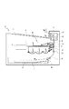
図2及び図3を用いて全体構成及び画像形成プロセスについて説明する。図2は、本実施の形態に係る画像形成装置の画像形成装置の装置本体A及びカートリッジBの断面図である。図3は、カートリッジBの断面図である。ここで、画像形成装置の装置本体Aとは、カートリッジBを除いた画像形成装置の部分である。 The overall configuration and the image formation process will be described with reference to FIGS. 2 and 3. FIG. 2 is a cross-sectional view of the apparatus main body A and the cartridge B of the image forming apparatus of the image forming apparatus according to the present embodiment. FIG. 3 is a cross-sectional view of the cartridge B. Here, the apparatus main body A of the image forming apparatus is a part of the image forming apparatus excluding the cartridge B.
<画像形成装置の全体構成>
図2に示す画像形成装置は、カートリッジBを装置本体Aに着脱自在とした電子写真技術を利用したレーザビームプリンタである。カートリッジBが装置本体Aに装着されたとき、カートリッジBの感光体ドラム62と対向する位置に露光装置3(レーザスキャナユニット)が配置されている。また、カートリッジBの下側に画像形成対象となる記録媒体(以下、シート材P)を収納したシートトレイ4が配置されている。
<Overall configuration of image forming device>
The image forming apparatus shown in FIG. 2 is a laser beam printer using electrophotographic technology in which the cartridge B is detachably attached to and attached to the apparatus main body A. When the cartridge B is mounted on the apparatus main body A, the exposure apparatus 3 (laser scanner unit) is arranged at a position facing the
更に、装置本体Aには、シート材Pの搬送方向Dに沿って、ピックアップローラ5a、給送ローラ対5b、搬送ローラ対5c、転写ガイド6、転写ローラ7、搬送ガイド8、定着装置9、排出ローラ対10、排出トレイ11等が順次配置されている。なお、定着装置9は、加熱ローラ9a及び加圧ローラ9bにより構成されている。
Further, the apparatus main body A includes a
<画像形成プロセス>
次に、画像形成プロセスの概略を説明する。プリントスタート信号に基づいて、感光体ドラム62は矢印R方向に所定の周速度(プロセススピード)をもって回転駆動される。バイアス電圧が印加された帯電手段としての帯電ローラ66は、図3に示すように感光体ドラム62の外周面に接触し、感光体ドラム62の外周面を一様均一に帯電する。
<Image formation process>
Next, the outline of the image formation process will be described. Based on the print start signal, the
露光装置3は、画像情報に応じたレーザ光Lを出力する。そのレーザ光LはカートリッジBの現像容器23とクリーニング枠体71の間を通り、感光体ドラム62の外周面を走査露光する。これにより、感光体ドラム62の外周面には画像情報に対応した静電潜像が形成される。
The exposure apparatus 3 outputs the laser beam L according to the image information. The laser beam L passes between the developing
一方、現像装置としての現像ユニット20において、トナー室29内のトナーTは、第1搬送部材43、第2搬送部材44、第3搬送部材50の回転によって撹拌、搬送され、トナー供給室28に送り出される。トナーTは、マグネットローラ34(固定磁石)の磁力により、現像手段としての現像ローラ32の表面に担持される。現像ローラ32の表面に担持されたトナーTは、現像ブレード42によって、摩擦帯電されつつ現像ローラ32周面の層厚が規制される。そして、現像ローラ32上に形成されたトナー層によって感光体ドラム62の静電潜像はトナー像として可視像化される。
On the other hand, in the developing
また、図2に示すように、レーザ光Lの出力タイミングとあわせて、ピックアップローラ5a、給送ローラ対5b、搬送ローラ対5cによって、装置本体Aの下部に収納されたシート材Pがシートトレイ4から給送される。そして、そのシート材Pが転写ガイド6を経由して、感光体ドラム62と転写ローラ7との間の転写位置へ供給される。この転写位置において、トナー像は感光体ドラム62からシート材Pに順次転写されていく。
Further, as shown in FIG. 2, the sheet material P housed in the lower part of the apparatus main body A by the
トナー像が転写されたシート材Pは、感光体ドラム62から分離されて搬送ガイド8に沿って定着装置9に搬送される。そしてシート材Pは、定着装置9を構成する加熱ローラ9aと加圧ローラ9bとのニップ部を通過する。このニップ部で加圧・加熱定着処理が行われてトナー像はシート材Pに定着される。トナー像の定着処理を受けたシート材Pは、排出ローラ対10まで搬送され、排出トレイ11に排出される。
The sheet material P to which the toner image is transferred is separated from the
一方、図3に示すように、転写後の感光体ドラム62は、クリーニング手段としてのクリーニング部材77により外周面上の残留トナーが除去されて、再び、画像形成プロセスに使用される。感光体ドラム62から除去されたトナーはクリーニングユニット60の廃トナー室71bに貯蔵される。なお、上記において、帯電ローラ66、現像ローラ32、クリーニング部材77が感光体ドラム62に作用するプロセス手段である。
On the other hand, as shown in FIG. 3, the
<カートリッジ全体の構成>
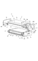
次にカートリッジBの全体構成について図3、図6、図7を用いて説明する。図3はカートリッジBの断面図、図6及び図7は、カートリッジBの構成を説明する斜視図である。なお本実施例においては各部品を結合する際のビスに関しては省略して説明する。
<Structure of the entire cartridge>
Next, the overall configuration of the cartridge B will be described with reference to FIGS. 3, 6, and 7. FIG. 3 is a cross-sectional view of the cartridge B, and FIGS. 6 and 7 are perspective views illustrating the configuration of the cartridge B. In this embodiment, the screws for connecting the parts will be omitted.
図3を用いて、本実施例におけるカートリッジBについて更に詳しく説明する。カートリッジBは、クリーニングユニット60と、現像ユニット20と、を有する。クリーニングユニット60と現像ユニット20は、回動可能に一体化され、クリーニングユニット60の現像ローラ32と現像ユニット20の感光体ドラム62が当接離間可能とされている。なお一般にプロセスカートリッジ(カートリッジ)とは、感光体ドラムと、これに作用するプロセス手段としての帯電手段、現像手段及びクリーニング手段の少なくとも一つを一体的にカートリッジ化して、画像形成装置の本体に対して着脱可能としたものである。本発明においては、カートリッジは、本発明に従うクリーニングユニットを少なくとも有する。
The cartridge B in this embodiment will be described in more detail with reference to FIG. The cartridge B includes a
クリーニングユニット60は、感光体ドラム62と、帯電ローラ66と、クリーニング部材77と、これらを支持するクリーニング枠体71と、クリーニング枠体71に溶着等で固定された蓋部材72を有する。クリーニングユニット60において、帯電ローラ66、クリーニング部材77は、それぞれ感光体ドラム62の外周面上に接触して配置されている。
The
クリーニング部材77は、ゴム(弾性部材)で形成されたブレード状のゴムブレード部材77aと、ゴムブレードを支持する支持部材77bと、を有する。ゴムブレード部材77aは、感光体ドラム62の回転方向に対してカウンター方向に感光体ドラム62に当接されている。即ち、ゴムブレード部材77aは、その先端部が感光体ドラム62の回転方向の上流側を向くように、感光体ドラム62に当接されている。クリーニング部材77によって感光体ドラム62の表面から除去された廃トナーは、廃トナー搬送部材54によりクリーニング枠体71と蓋部材72によって形成された廃トナー室71bに搬送される。廃トナー搬送部材54はクランク部材86と係合し、クランク部材86から駆動伝達されることで図中矢印Q方向に回転し、廃トナーを搬送する。また廃トナー室71bの廃トナーが漏れることを防止するため、感光体ドラム62に当接するようにして、感光体ドラム62に対向するクリーニング枠体71の縁部にスクイシート65が設けられている。
The cleaning
感光体ドラム62は、クリーニングユニット60に駆動源である本体駆動モータ(不図示)の駆動力を伝達することにより、画像形成動作に応じて、図中矢印R方向に回転駆動される。帯電ローラ66は、クリーニング枠体71の長手方向(感光体ドラム62の回転軸線方向と略平行)の両端部側において、帯電ローラ軸受67を介し、クリーニングユニット60に回転可能に取り付けられている。帯電ローラ66は、帯電ローラ軸受67が付勢部材68により感光体ドラム62に向けて加圧されることで感光体ドラム62に圧接され、感光体ドラム62の回転に従動回転するように構成されている。
The
一方、現像ユニット20は、現像ローラ32と、現像ローラ32を支持する現像容器23と、現像ブレード42等を有する。現像ローラ32内にはマグネットローラ34が設けられている。現像容器23と底部材22によって形成されたトナー室29には、第1搬送部材43、第2搬送部材44、第3搬送部材50が設けられている。第1搬送部材43、第2搬送部材44、第3搬送部材50は、トナー室29に収容されたトナーを撹拌すると共に、トナー供給室28へトナーを搬送する。また現像ユニット20において、トナー供給室28の開口部に配置された現像ローラ32上のトナー層を規制するための現像ブレード42が配置されている。現像ローラ32には間隔保持部材38が現像ローラ32の両端部に取り付けられており、間隔保持部材38と感光体ドラム62が当接することで、現像ローラ32は感光体ドラム62と微少隙間をもって保持されている(図6)。また更に、現像ユニット20からトナーが漏れることを防止するため、現像ローラ32に当接するようにして、現像ローラ32に対向する底部材22の縁部に吹き出し防止シート33が設けられている。
On the other hand, the developing
このようなカートリッジBは、図6及び図7に示すようにクリーニングユニット60と現像ユニット20を形成し、一体化することにより構成される。
Such a cartridge B is configured by forming and integrating the
クリーニングユニット60は、駆動側ドラムフランジ63及び非駆動側ドラムフランジ64が取り付けられた感光体ドラム62がクリーニング枠体71と蓋部材72に対し、ドラム軸78と、第1支持部としてのドラム軸受73と、で回転可能とされる。より具体的には駆動側は、ドラム軸受73の穴部73aにドラムフランジ63が挿入されることで回転可能に支持される。一方、非駆動側は、ドラム軸78がクリーニング枠体71に設けられた穴部71cに圧入され、非駆動側ドラムフランジ64の穴部(不図示)と係合し、回転可能に支持される。なお、駆動側ドラムフランジ63は、装置本体Aから駆動を受ける駆動力受け部63aと、現像ローラ32の駆動側に設けられた現像ローラギア39に駆動を伝達するためのフランジギア部63bと、を有している。
In the
クリーニング枠体71の両端側には、現像ユニット20を支持するための駆動側ドラムサイド部材69と、非駆動側ドラムサイド部材70が取り付けられる。駆動側ドラムサイド部材69は、長穴部69dと位置決め穴69cを有する。長穴部69dにクリーニング枠体71の駆動側のボス71aが、また位置決め穴69cにクリーニング枠体71に取り付けられたドラム軸受73の支持部73bが、それぞれ挿入されることで、クリーニング枠体71に固定される。一方、非駆動側ドラムサイド部材70は、長穴部70dと位置決め穴70cを有する。穴部70dにクリーニング枠体71の非駆動側のボス71dが、また位置決め穴70cにドラム軸78を挿入する円筒ボスの外径部71eが、それぞれ挿入されることで、クリーニング枠体71に固定される。
A drive-side
そして、現像ユニット20は、現像ローラ32が両端に設けられた軸受部材37で現像容器23に対して回転可能に取り付けられ、形成される。現像ユニット20の両側には、駆動側ドラムサイド部材69と非駆動側ドラムサイド部材70が移動可能に取付られることによってカートリッジBが形成される。具体的には現像ユニット20は、駆動側においては、駆動側現像サイド部材26に現像第1支持部26aと現像第2支持部26bを、また駆動側ドラムサイド部材69の第1長穴69aと第2長穴69bを、有するものとされている。駆動側ドラムサイド部材69の第1長穴69aに駆動側現像サイド部材26の現像第1支持部26aが、また駆動側ドラムサイド部材69の第2長穴69bに駆動側現像サイド部材26の現像第2支持部26bが、それぞれ係合するように形成される。同様に、現像ユニット20は、非駆動側において、非駆動側現像サイド部材27に現像第3支持部27aと現像第4支持部27bを、また非駆動側ドラムサイド部材70に第3長穴70aと第4長穴70bを、有するものとされている。非駆動側ドラムサイド部材70の第3長穴70aに非駆動側現像サイド部材27の現像第3支持部27aが、また非駆動側ドラムサイド部材70の第4長穴70bに非駆動側現像サイド部材27の現像第4支持部27bが、それぞれ係合するように形成される。このようにして、現像ユニット20は、駆動側ドラムサイド部材69と非駆動側ドラムサイド部材70を介してクリーニングユニット60に支持され、クリーニングユニット60と現像ユニット20は一体化される。
Then, the developing
このとき、現像第2支持部26bに対して第2長穴69bは、また現像第4支持部27bに対して第4長穴70bは、大きく形成されている。これにより、第1長穴69aに係合した現像第1支持部26aを、また第3長穴70aに係合した現像第3支持部27aを、回動中心として回動可能に形成される。そして、駆動側においては、駆動側ドラムサイド部材69のボス69eに駆動側付勢部材46Rの第1穴部46Raが、また駆動側現像サイド部材26のボス26cに駆動側付勢部材46Rの第2穴部46Rbが、それぞれ掛けられている。同様に、非駆動側ドラムサイド部材70のボス70eに非駆動側付勢部材46Fの第1穴部46Faが、また非駆動側現像サイド部材27のボス27cに非駆動側付勢部材46Fの第2穴部46Fbが、それぞれ掛けられている。本実施例においては、駆動側付勢部材46R、非駆動側付勢部材46Fとして引っ張りバネを用い、バネの付勢力により現像ユニット20をクリーニングユニット60に付勢させ、現像ローラ32を感光体ドラム62の方向へ確実に押し付けるよう構成している。このようにして、現像ローラ32の両端部に取り付けられた間隔保持部材38によって、現像ローラ32は感光体ドラム62から所定の間隔をもって保持されるように形成される。
At this time, the second elongated hole 69b is formed larger than the developed second support portion 26b, and the fourth
<カートリッジ着脱>
次に、装置本体Aに対するカートリッジBの着脱について、図4及び図5を用いて説明する。図4は、カートリッジBを着脱するために開閉扉13を開いた装置本体Aの斜視図である。図5は、カートリッジBを着脱するために開閉扉13を開いた装置本体AとカートリッジBの斜視図である。
<Cartridge attachment / detachment>
Next, attachment / detachment of the cartridge B to / from the apparatus main body A will be described with reference to FIGS. 4 and 5. FIG. 4 is a perspective view of the apparatus main body A in which the opening / closing
装置本体Aには開閉扉13が回動可能に取り付けられている。この開閉扉13を開くと装置本体Aの非駆動側に設けられた非駆動側板16内にカートリッジ装着口17が設けられている。そしてカートリッジ装着口17内にはカートリッジBを装置本体Aに装着するためのカートリッジガイド12が備えてあり、カートリッジBは図中矢印C方向にカートリッジガイド12に沿って装置本体A内に装着される。
An opening / closing
ここで矢印方向CはカートリッジBを装置本体Aに対して感光体ドラム62の軸線方向に沿って非駆動側から駆動側に装着する方向を示すものである。すなわちカートリッジBにおいて非駆動側が装着方向上流側、駆動側が装着方向下流側となる。
Here, the arrow direction C indicates a direction in which the cartridge B is mounted on the apparatus main body A from the non-driving side to the driving side along the axial direction of the
装置本体A内にはカートリッジBの駆動力受け部63a(図6)に駆動を伝達するための駆動軸14が設けられている。駆動軸14は装置本体Aのモータ(不図示)により駆動され、これにより、駆動力受け部63aと結合している感光体ドラム62が装置本体Aから駆動力を受けて回転する。さらに、帯電ローラ66、現像ローラ32は、装置本体Aの給電部(不図示)より給電される。
A
<カートリッジ支持構成>
次に図1、図8、図9を用いてカートリッジBを装置本体Aに支持する構成について説明する。図1は、装置本体AとカートリッジBを非駆動側から駆動側を見たときの側面図である。図8は、装置本体Aを非駆動側から駆動側を見たときの側面図である。図9は、装置本体AとカートリッジBを駆動側から非駆動側に見た側面図である。
<Cartridge support configuration>
Next, a configuration in which the cartridge B is supported by the apparatus main body A will be described with reference to FIGS. 1, 8 and 9. FIG. 1 is a side view of the apparatus main body A and the cartridge B when the driving side is viewed from the non-driving side. FIG. 8 is a side view of the apparatus main body A when the driving side is viewed from the non-driving side. FIG. 9 is a side view of the apparatus main body A and the cartridge B as viewed from the drive side to the non-drive side.
図8に示すように装置本体AにはカートリッジBを支持するための支持部としての駆動側板15と非駆動側板16が設けられている。駆動側板15には、第1規制部としての第1支持部15a及び第2支持部15b、さらにカートリッジBの回転支持部としての長穴15cが設けられている。そして非駆動側板16には、第2規制部としての第3支持部16a及び第2支持部16bが設けられている。
As shown in FIG. 8, the apparatus main body A is provided with a
具体的には、駆動側においては、図9に示すようにカートリッジBの荷重を支持するため、鉛直下方へ突出した第1当接部73yがドラム軸受73に設けられており、第1支持部15aと当接する構成となっている。また第1支持部とは交差する方向へ突出し、第1支持部と直交する方向(水平方向)の位置を決めるための第2当接部73xがドラム軸受73に設けられており、駆動側板15の第2支持部15bに当接する構成となっている。つまりドラム軸受73(第1位置決め部)は、所定方向に突出した第1当接部73yが第1支持部15aで支持され、第1当接部73yと交差する方向に突出した第2当接部73xが第2支持部15bで位置規制される構成とされている。さらに駆動側においては、駆動側ドラムサイド部材69に設けられたボス69f(図6)が駆動側板15に設けられた長穴15cに進入して、カートリッジBが駆動側板15で支持された構成とされている。
Specifically, on the drive side, in order to support the load of the cartridge B as shown in FIG. 9, a
一方、非駆動側においては、図1に示すように第3支持部16aと当接する第2位置決め部としてのクリーニング枠体71には、カートリッジBの荷重を支持するための鉛直下方へ突出した第3当接部71fが設けられている。また第3支持部とは交差する方向へ突出し、第3支持部と直交する方向(水平方向)の位置を決めるためのクリーニング枠体71には、第4当接部71gが設けられており、非駆動側板16の第4支持部16bに当接する構成となっている。つまり、クリーニング枠体71(第2位置決め部)は、第3支持部16aでカートリッジBの荷重が支持され、第4支持部16bにより位置規制される構成とされている。
On the other hand, on the non-driving side, as shown in FIG. 1, the
ここで駆動側において、カートリッジBが装置本体Aに装着された状態における感光体ドラム62の中心(回転軸)から第1支持部15aの距離をRx、第2支持部15bまでの距離をRyと定義する。また非駆動側において、カートリッジBが装置本体Aに装着された状態における感光体ドラム62の中心(回転軸)から第3支持部16aの距離をFx、第4支持部16bまでの距離をFyと定義する。
Here, on the drive side, the distance from the center (rotation axis) of the
このとき本実施例においては、Fx>RxかつFy>Ryの関係が成り立つ構成とする。言い換えると、装置本体Aに装着された状態における感光体ドラム62の中心(回転軸)からの距離は、第1当接部73yに比べ第3当接部71fの方が大きく、また第2当接部73xに比べ第4当接部71gの方が大きくなるように構成している。すなわちカートリッジの着脱方向(感光体ドラム62の軸線方向)に対して直交する断面において、ドラム軸受73(第1位置決め部)に対して、クリーニング枠体71(第2位置決め部)が感光体ドラム62の中心(回転軸)から離れた構成としている。
At this time, in this embodiment, the relationship of Fx> Rx and Fy> Ry is established. In other words, the distance from the center (rotation axis) of the
これにより、カートリッジBをドラム軸線方向に装着する装置本体に対し構成において、カートリッジBが傷つくことを防止するため、非駆動側位置決めに対してカートリッジBを遠ざけた軌跡で装着する必要がなくなる。この結果、カートリッジBを退避させるスペースを無駄に大きくする必要がなく、装置本体の小型化を図りつつ、カートリッジB、例えば感光体ドラム62が傷つくことをより良く防止することができる。
As a result, in order to prevent the cartridge B from being damaged in the configuration of the apparatus main body in which the cartridge B is mounted in the drum axis direction, it is not necessary to mount the cartridge B in a trajectory away from the non-driving side positioning. As a result, it is not necessary to wastefully increase the space for retracting the cartridge B, and it is possible to better prevent the cartridge B, for example, the
なお、本実施例では、感光体ドラム62の中心(回転軸)から第3支持部16aの距離Fxと、感光体ドラム62の中心(回転軸)から第4支持部16bまでの距離Fyが異なる構成とした。より具体的には、鉛直方向に延びる距離Fyが水平方向に延びるFxに比べ、長い構成とした。カートリッジBは、装着時においては、カートリッジガイド12に沿って装置本体A内に装着される構成とされており、画像形成時に比べ、位置精度は劣るものの、水平方向において、所定の範囲に位置規制されている。このため、カートリッジB、例えば感光体ドラム62が傷つくことをより良く防止しつつ、非駆動側板16ひいては装置本体Bの小型化を図ることができ、装置本体Aの設計の自由度を向上させることができる。
In this embodiment, the distance Fx from the center (rotation axis) of the
さらには本実施例では、クリーニング枠体71(第2位置決め部)は感光体ドラム62の半径より感光体ドラム62の中心(回転軸)から離れた構成としている。これにより、カートリッジBを装置本体Aに装着する際、非駆動側板16の第3支持部16a、第2支持部16bがカートリッジBに当たり、傷などがつくことを防止することができる。
Further, in this embodiment, the cleaning frame 71 (second positioning portion) is configured to be separated from the center (rotation axis) of the
以上のように本実施例によれば、カートリッジBを装置本体Aに対しドラム軸線方向に装着する構成において、装置本体Aの小型化を図りつつ、カートリッジBが傷つくのを抑制することができる。 As described above, according to the present embodiment, in the configuration in which the cartridge B is mounted with respect to the apparatus main body A in the drum axis direction, it is possible to suppress the cartridge B from being damaged while reducing the size of the apparatus main body A.
なお、本実施例に記載されている構成部品の機能、材質、形状その相対配置などは、特に特定的な記載がない限りは、この発明の範囲をそれらのみに限定する趣旨のものではない。また本実施例においては、装置本体Aに対するカートリッジBの着脱について記載したが、本構成は装置本体Aに対するクリーニングユニットの着脱においても適用できる。 The functions, materials, shapes, and relative arrangements of the components described in the present embodiment are not intended to limit the scope of the present invention to those, unless otherwise specified. Further, in this embodiment, the attachment / detachment of the cartridge B to / from the apparatus main body A has been described, but this configuration can also be applied to the attachment / detachment of the cleaning unit to / from the apparatus main body A.
[実施例2]
次に、本発明の実施例2の形態を図9、図10に基づいて説明する。実施例1では、非駆動側において、クリーニング枠体71(第2位置決め部)に、第3支持部としての第3当接部71fと、第3支持部とは直交する方向を支持するための、第3支持部とは異なる第4支持部として第4当接部71gが設けられた構成とした。このようにして、クリーニング枠体71(第2位置決め部)の第3当接部71fは第3支持部16aに、また第2当接部71gは第4支持部16bに支持される構成とした。しかし、これに限らず、第3支持部と第4支持部を一つの部分に設けた構成としてもよい。以下に例を挙げ説明を行う。なお、本実施例においては、実施例1と異なる部分について詳細に説明する。実施例1と同様の構成については、同一の番号を付与し、詳細な説明は省略する。
[Example 2]
Next, the embodiment of Example 2 of the present invention will be described with reference to FIGS. 9 and 10. In the first embodiment, on the non-driving side, the cleaning frame body 71 (second positioning portion) is used to support the
実施例1同様、図9に示すように第1支持部15aと当接する第1位置決め部としてのドラム軸受73には、カートリッジBの荷重を支持するための第1支持部としての第1当接部73yが設けられている。また第1支持部とは直交する方向を支持するための第2支持部として、ドラム軸受73には、第2当接部73xが設けられており、駆動側板15の第2支持部15bに当接する構成となっている。つまり、第1位置決め部としてのドラム軸受73は、第1支持部15aと第2支持部15bにより支持される。また、駆動側ドラムサイド部材69についても、実施例1同様、ボス69fが設けられ(図6)、長穴15cに挿入されることにより、カートリッジBが駆動側板15で支持される。
Similar to the first embodiment, as shown in FIG. 9, the drum bearing 73 as the first positioning portion that comes into contact with the
本実施例では、図10に示すように、第3支持部16aと当接する第2位置決め部としてのクリーニング枠体71には、カートリッジBの荷重を支持するための第3支持部としての第3当接部71fが設けられている。なお図10は、装置本体AとカートリッジBを非駆動側から駆動側を見たときの側面図である。第3当接部
加えて第3当接部71f(第3支持部)となる部分と同一の部分には、第3支持部とは直交する方向を支持するための第4支持部として第2当接部第4当接部71gが設けられており、非駆動側板16の第4支持部16bに当接する構成となっている。つまり、第2位置決め部としてのクリーニング枠体71は、第3支持部16aと第4支持部16bにより支持される。
In this embodiment, as shown in FIG. 10, the
ここでカートリッジBが装置本体Aに装着された状態において、駆動側の感光体ドラム62の中心(回転軸線)から第1支持部までの距離をRx、駆動側の感光体ドラム62の中心(回転軸線)から第2支持部までの距離をRyと定義する。また非駆動側の感光体ドラム62の中心(回転軸線)から第3支持部までの距離をFx、非駆動側の感光体ドラム62の中心(回転軸線)から第4支持部までの距離をFyと定義する。
Here, in a state where the cartridge B is mounted on the apparatus main body A, the distance from the center (rotation axis) of the
このとき本実施例においては、Fx>RxかつFx>感光体ドラム62の半径の関係が成り立つ構成とする。言い換えると、感光体ドラム62の中心(回転軸)から第4当接部71gまでの距離は、感光体ドラム62の中心(回転軸)から第2当接部73xまでの距離、また感光体ドラム62の半径に比べが大きくなるように構成されている。さらに、感光体ドラム62の中心(回転軸線)から第3当接部71fと接触する第3支持部16aまでの距離Flは、Fxが延びる方向に対して交差する方向に延び、感光体ドラム62の半径より大きくなる位置とされている。すなわち、カートリッジの着脱方向に対して直交する断面において、感光体ドラム62の中心(回転軸線)から感光体ドラム62の半径より大きい距離を有するように、第3支持部16aと第4支持部16bを設ける。さらに、第3支持部16aは第1支持部15aに比べて、かつ/または第4支持部16bは第2支持部15bに比べて、感光体ドラム62の中心(回転軸線)からの距離が大きい構成とする。つまり少なくとも一へ延びる所定方向においては、非駆動側支持部が駆動側支持部に比べ、感光体ドラム62の中心(回転軸線)からの距離が大きくなるように構成されている。
At this time, in this embodiment, the relationship of the radius of Fx> Rx and Fx>
これにより、カートリッジBをドラム軸線方向に装着する装置本体に対し構成において、カートリッジBが傷つくことを防止するため、非駆動側位置決めに対してカートリッジBを遠ざけた軌跡で装着する必要がなくなる。この結果、カートリッジBを退避させるスペースを無駄に大きくする必要がなく、装置本体の小型化を図りつつ、カートリッジB、例えば感光体ドラム62が傷つくことをより良く防止することができる。
As a result, in order to prevent the cartridge B from being damaged in the configuration of the apparatus main body in which the cartridge B is mounted in the drum axis direction, it is not necessary to mount the cartridge B in a trajectory away from the non-driving side positioning. As a result, it is not necessary to wastefully increase the space for retracting the cartridge B, and it is possible to better prevent the cartridge B, for example, the
また本実施例では、感光体ドラム62の中心からの距離が、第1支持部15aに比べて第3支持部16aの方が、もしくは第2支持部15bに比べて第4支持部16bの方が、大きい構成であればよい。すなわち、いずれかの条件を満たす構成であれば、Fy>Ryの関係が成り立つ構成としなくてもよい。したがって、カートリッジB、例えば感光体ドラム62が傷つくことをより良く防止しつつ、非駆動側板16ひいては装置本体Bの小型化を図ることができ、装置本体Aの設計の自由度を向上させることができる。
Further, in this embodiment, the distance from the center of the
さらには本実施例では、クリーニング枠体71(第2位置決め部)は感光体ドラム62の半径より感光体ドラム62の中心(回転軸線)から離れた構成としている。これにより、カートリッジBを装置本体Aに装着する際、非駆動側板16の第3支持部16a、第2支持部16bがカートリッジBに当たり、傷などがつくことを防止することができる。
Further, in this embodiment, the cleaning frame 71 (second positioning portion) is configured to be separated from the center (rotation axis) of the
14 駆動軸
15 駆動側板
16 非駆動側板
20 現像ユニット
23 現像容器
26 駆動側現像サイド部材
27 非駆動側現像サイド部材
32 現像ローラ(現像剤担持体)
37 軸受部材
38 間隔保持部材
42 現像ブレード(現像剤規制部材)
46R 駆動側付勢部材
46F 非駆動側付勢部材
60 クリーニングユニット
62 感光体ドラム
63 駆動側ドラムフランジ
64 非駆動側ドラムフランジ
69 駆動側ドラムサイド部材
70 非駆動側ドラムサイド部材
71 クリーニング枠体
71g 第1支持部(第3当接部)
71f 第2支持部(第4当接部)
73 ドラム軸受
73y 第3支持部(第1当接部)
73x 第4支持部(第2当接部)
77 クリーニング部材
78 ドラム軸
A 装置本体
B プロセスカートリッジ(カートリッジ)
14
37
46R Drive
71f 2nd support part (4th contact part)
73
73x 4th support (2nd contact)
77
Claims (8)
前記感光ドラムに作用するように構成されたプロセス手段と、
回転軸線を中心に回転可能になるように前記感光ドラムを支持し、前記プロセス手段を支持する枠体と、
を有し、
画像形成装置の装置本体に対して前記回転軸線の方向に沿う方向である装着方向に着脱できるように構成されたカートリッジにおいて、
前記枠体は、
前記装着方向の下流側の前記枠体の端部に設けられた第1被位置決め部であって、前記装置本体に当接して前記装着方向に直交する方向の前記装置本体に対する前記カートリッジの位置を決めるための第1被位置決め部と、
前記装着方向の上流側の前記枠体の端部に設けられた第2被位置決め部であって、前記装置本体に当接して前記直交する方向の前記カートリッジの位置を決めるための第2被位置決め部と、
を有し、
前記装着方向に見たときに、前記回転軸線から離れる方向である所定方向における前記回転軸線から第1被位置決め部までの距離よりも、前記所定方向における前記回転軸線から前記第2被位置決め部までの距離の方が長く、
前記第2被位置決め部は、前記装着方向に見たときに、前記所定方向へ突出した第1突出部と、前記所定方向と交差する方向であって前記回転軸線から離れる方向へ突出した第2突出部と、を含み、
前記感光ドラムの回転方向において前記第1突出部と前記第2突出部との間には隙間が設けられていることを特徴とするカートリッジ。 Photosensitive drum and
A process means configured to act on the photosensitive drum and
A frame body that supports the photosensitive drum so as to be rotatable about the rotation axis and supports the process means, and
Have,
In a cartridge configured so that it can be attached to and detached from the main body of the image forming apparatus in the mounting direction which is the direction along the direction of the rotation axis.
The frame is
A first positioned portion provided at the end of the frame on the downstream side in the mounting direction, and the position of the cartridge with respect to the device body in a direction orthogonal to the mounting direction in contact with the device body. The first positioned part for determining and
A second positioned portion provided at the end of the frame on the upstream side in the mounting direction, which is a second positioned portion for abutting the main body of the device and determining the position of the cartridge in the orthogonal direction. Department and
Have,
When viewed in the mounting direction, from the rotation axis in the predetermined direction to the second positioned portion rather than the distance from the rotation axis to the first positioned portion in a predetermined direction away from the rotation axis. If the distance is rather long,
The second positioned portion protrudes in a direction intersecting the predetermined direction and away from the rotation axis with the first protruding portion protruding in the predetermined direction when viewed in the mounting direction. Including protrusions,
A cartridge characterized in that a gap is provided between the first protruding portion and the second protruding portion in the rotation direction of the photosensitive drum.
前記カートリッジが前記回転軸線に沿った装着方向に着脱可能な装置本体であって、第1側板と第2側板を有する装置本体と、
を備えた画像形成装置において、
前記カートリッジの前記枠体は、前記装着方向の下流側の前記枠体の端部に設けられた第1被位置決め部と、前記装着方向の上流側の前記枠体の端部に設けられた第2被位置決め部と、
を有し、
前記第1側板は、前記装置本体の前記装着方向の下流側に配置され、前記カートリッジの前記第1被位置決め部に当接することで前記装着方向に直交する方向における前記装置本体に対する前記カートリッジの位置を決めるための第1位置決め部を有し、
前記第2側板は、前記装置本体の前記装着方向の上流側に配置され、前記カートリッジの前記第2被位置決め部に当接することで前記直交する方向における前記装置本体に対する前記カートリッジの位置を決めるための第2位置決め部を有し、
前記装着方向に見たときに、前記回転軸線から離れる方向である所定方向における前記回転軸線から第1被位置決め部までの距離よりも、前記所定方向における前記回転軸線から前記第2被位置決め部までの距離の方が長く、
前記第2被位置決め部は、前記装着方向に見たときに、前記所定方向へ突出した第1突出部と、前記所定方向と交差する方向であって前記回転軸線から離れる方向へ突出した第2突出部と、を含み、
前記感光ドラムの回転方向において前記第1突出部と前記第2突出部との間には隙間が設けられていることを特徴とする画像形成装置。 A cartridge having a photosensitive drum, a process means acting on the photosensitive drum, and a frame body that supports the photosensitive drum so as to be rotatable about a rotation axis and supports the process means.
A device body in which the cartridge is removable in the mounting direction along the rotation axis, and a device body having a first side plate and a second side plate.
In an image forming apparatus equipped with
The frame body of the cartridge is provided at a first positioned portion provided at an end portion of the frame body on the downstream side in the mounting direction and at an end portion of the frame body on the upstream side in the mounting direction. 2 Positioned part and
Have,
The first side plate is arranged on the downstream side of the apparatus main body in the mounting direction, and the position of the cartridge with respect to the apparatus main body in a direction orthogonal to the mounting direction by abutting on the first positioned portion of the cartridge. Has a first positioning unit for determining
The second side plate is arranged on the upstream side of the apparatus main body in the mounting direction, and abuts on the second positioned portion of the cartridge to determine the position of the cartridge with respect to the apparatus main body in the orthogonal direction. Has a second positioning part of
When viewed in the mounting direction, from the rotation axis in the predetermined direction to the second positioned portion rather than the distance from the rotation axis to the first positioned portion in a predetermined direction away from the rotation axis. If the distance is rather long,
The second positioned portion protrudes in a direction intersecting the predetermined direction and away from the rotation axis with the first protruding portion protruding in the predetermined direction when viewed in the mounting direction. Including protrusions,
An image forming apparatus characterized in that a gap is provided between the first protruding portion and the second protruding portion in the rotation direction of the photosensitive drum.
Priority Applications (4)
| Application Number | Priority Date | Filing Date | Title |
|---|---|---|---|
| JP2016091441A JP6896376B2 (en) | 2016-04-28 | 2016-04-28 | Cartridge and image forming device |
| US15/496,342 US10156827B2 (en) | 2016-04-28 | 2017-04-25 | Cartridge and image forming apparatus |
| EP17168376.6A EP3239784B1 (en) | 2016-04-28 | 2017-04-27 | Cartridge and image forming apparatus |
| CN201710290098.2A CN107340702B (en) | 2016-04-28 | 2017-04-28 | Cartridge and image forming apparatus |
Applications Claiming Priority (1)
| Application Number | Priority Date | Filing Date | Title |
|---|---|---|---|
| JP2016091441A JP6896376B2 (en) | 2016-04-28 | 2016-04-28 | Cartridge and image forming device |
Publications (3)
| Publication Number | Publication Date |
|---|---|
| JP2017198930A JP2017198930A (en) | 2017-11-02 |
| JP2017198930A5 JP2017198930A5 (en) | 2019-06-06 |
| JP6896376B2 true JP6896376B2 (en) | 2021-06-30 |
Family
ID=58638752
Family Applications (1)
| Application Number | Title | Priority Date | Filing Date |
|---|---|---|---|
| JP2016091441A Active JP6896376B2 (en) | 2016-04-28 | 2016-04-28 | Cartridge and image forming device |
Country Status (4)
| Country | Link |
|---|---|
| US (1) | US10156827B2 (en) |
| EP (1) | EP3239784B1 (en) |
| JP (1) | JP6896376B2 (en) |
| CN (1) | CN107340702B (en) |
Family Cites Families (15)
| Publication number | Priority date | Publication date | Assignee | Title |
|---|---|---|---|---|
| JPH02135381A (en) * | 1988-11-16 | 1990-05-24 | Konica Corp | Color image forming device |
| JPH10142884A (en) * | 1996-11-12 | 1998-05-29 | Konica Corp | Color image forming device |
| JP4378299B2 (en) * | 2004-02-20 | 2009-12-02 | キヤノン株式会社 | Process cartridge and electrophotographic image forming apparatus |
| CN100440072C (en) * | 2004-07-30 | 2008-12-03 | 佳能株式会社 | Process cartridge and electrophotographic image forming apparatus |
| JP4646214B2 (en) * | 2005-03-17 | 2011-03-09 | 株式会社リコー | Image forming apparatus |
| JP4577578B2 (en) * | 2005-12-20 | 2010-11-10 | 富士ゼロックス株式会社 | Image forming apparatus, image forming structure, mounting method of image forming structure, and drawing method of image forming structure |
| JP4280770B2 (en) * | 2006-01-11 | 2009-06-17 | キヤノン株式会社 | Process cartridge and electrophotographic image forming apparatus |
| JP5127565B2 (en) * | 2008-05-23 | 2013-01-23 | キヤノン株式会社 | Cartridge and image forming apparatus |
| JP5004870B2 (en) | 2008-05-23 | 2012-08-22 | キヤノン株式会社 | Process cartridge and electrophotographic image forming apparatus |
| JP4630932B2 (en) * | 2008-05-27 | 2011-02-09 | キヤノン株式会社 | Process cartridge and image forming apparatus |
| JP4701266B2 (en) * | 2008-05-27 | 2011-06-15 | キヤノン株式会社 | Process cartridge and electrophotographic image forming apparatus |
| JP4869289B2 (en) * | 2008-05-27 | 2012-02-08 | キヤノン株式会社 | Process cartridge and electrophotographic image forming apparatus |
| KR101579821B1 (en) * | 2009-01-14 | 2015-12-28 | 삼성전자 주식회사 | Image forming apparatus |
| JP5182313B2 (en) * | 2010-03-24 | 2013-04-17 | ブラザー工業株式会社 | Process cartridge |
| JP5959924B2 (en) * | 2012-04-26 | 2016-08-02 | キヤノン株式会社 | Cleaning device, process cartridge, and image forming apparatus |
-
2016
- 2016-04-28 JP JP2016091441A patent/JP6896376B2/en active Active
-
2017
- 2017-04-25 US US15/496,342 patent/US10156827B2/en active Active
- 2017-04-27 EP EP17168376.6A patent/EP3239784B1/en active Active
- 2017-04-28 CN CN201710290098.2A patent/CN107340702B/en active Active
Also Published As
| Publication number | Publication date |
|---|---|
| US10156827B2 (en) | 2018-12-18 |
| US20170315504A1 (en) | 2017-11-02 |
| CN107340702B (en) | 2021-07-06 |
| CN107340702A (en) | 2017-11-10 |
| JP2017198930A (en) | 2017-11-02 |
| EP3239784B1 (en) | 2021-06-09 |
| EP3239784A1 (en) | 2017-11-01 |
Similar Documents
| Publication | Publication Date | Title |
|---|---|---|
| JP6566627B2 (en) | Cartridge and image forming apparatus using the same | |
| US11449001B2 (en) | Cartridge and image forming apparatus | |
| JP2014071126A (en) | Cartridge, process cartridge, and image forming apparatus | |
| JP2003208074A (en) | Process cartridge and electrophotographic image forming device | |
| JP6465631B2 (en) | Cartridge and image forming apparatus | |
| CN111352327B (en) | Developing device, process cartridge, and image forming apparatus | |
| JP6667249B2 (en) | cartridge | |
| KR102064638B1 (en) | Cartridge and image forming apparatus | |
| US9857767B2 (en) | Process cartridge and image forming apparatus | |
| KR101985572B1 (en) | Feeding device, process cartridge and image forming apparatus | |
| JP6808311B2 (en) | Electrophotographic photosensitive drum unit, cartridge, and flange member | |
| JP6896376B2 (en) | Cartridge and image forming device | |
| KR102344241B1 (en) | Cartridge and image forming apparatus | |
| JP6887792B2 (en) | Development unit and process cartridge | |
| JP6381378B2 (en) | Developing device, process cartridge, and image forming apparatus | |
| JP6723800B2 (en) | Conveying device, process cartridge, and image forming apparatus | |
| JP2003131542A (en) | Process cartridge and electrophotographic image forming device | |
| JP2019204116A (en) | Cartridge and image forming apparatus using the same |
Legal Events
| Date | Code | Title | Description |
|---|---|---|---|
| A521 | Request for written amendment filed |
Free format text: JAPANESE INTERMEDIATE CODE: A523 Effective date: 20190424 |
|
| A621 | Written request for application examination |
Free format text: JAPANESE INTERMEDIATE CODE: A621 Effective date: 20190424 |
|
| A977 | Report on retrieval |
Free format text: JAPANESE INTERMEDIATE CODE: A971007 Effective date: 20200219 |
|
| A131 | Notification of reasons for refusal |
Free format text: JAPANESE INTERMEDIATE CODE: A131 Effective date: 20200303 |
|
| A601 | Written request for extension of time |
Free format text: JAPANESE INTERMEDIATE CODE: A601 Effective date: 20200501 |
|
| A521 | Request for written amendment filed |
Free format text: JAPANESE INTERMEDIATE CODE: A523 Effective date: 20200701 |
|
| A131 | Notification of reasons for refusal |
Free format text: JAPANESE INTERMEDIATE CODE: A131 Effective date: 20201222 |
|
| A521 | Request for written amendment filed |
Free format text: JAPANESE INTERMEDIATE CODE: A523 Effective date: 20210217 |
|
| TRDD | Decision of grant or rejection written | ||
| A01 | Written decision to grant a patent or to grant a registration (utility model) |
Free format text: JAPANESE INTERMEDIATE CODE: A01 Effective date: 20210511 |
|
| A61 | First payment of annual fees (during grant procedure) |
Free format text: JAPANESE INTERMEDIATE CODE: A61 Effective date: 20210609 |
|
| R151 | Written notification of patent or utility model registration |
Ref document number: 6896376 Country of ref document: JP Free format text: JAPANESE INTERMEDIATE CODE: R151 |