JP7003612B2 - Anomaly detection device and anomaly detection program - Google Patents
Anomaly detection device and anomaly detection program Download PDFInfo
- Publication number
- JP7003612B2 JP7003612B2 JP2017236224A JP2017236224A JP7003612B2 JP 7003612 B2 JP7003612 B2 JP 7003612B2 JP 2017236224 A JP2017236224 A JP 2017236224A JP 2017236224 A JP2017236224 A JP 2017236224A JP 7003612 B2 JP7003612 B2 JP 7003612B2
- Authority
- JP
- Japan
- Prior art keywords
- posture
- region
- head
- driver
- sign
- Prior art date
- Legal status (The legal status is an assumption and is not a legal conclusion. Google has not performed a legal analysis and makes no representation as to the accuracy of the status listed.)
- Active
Links
- 238000001514 detection method Methods 0.000 title claims description 51
- 230000036544 posture Effects 0.000 claims description 160
- 208000028752 abnormal posture Diseases 0.000 claims description 90
- 230000005856 abnormality Effects 0.000 claims description 59
- 239000000872 buffer Substances 0.000 claims description 54
- 238000000034 method Methods 0.000 claims description 51
- 230000008569 process Effects 0.000 claims description 49
- 230000007717 exclusion Effects 0.000 claims description 39
- 239000002243 precursor Substances 0.000 claims description 25
- 238000003384 imaging method Methods 0.000 claims description 16
- 238000012545 processing Methods 0.000 claims description 11
- 230000014759 maintenance of location Effects 0.000 claims description 10
- 230000033228 biological regulation Effects 0.000 claims description 4
- 210000003128 head Anatomy 0.000 description 75
- 230000007704 transition Effects 0.000 description 37
- 238000010191 image analysis Methods 0.000 description 11
- 238000012544 monitoring process Methods 0.000 description 9
- 230000004048 modification Effects 0.000 description 8
- 238000012986 modification Methods 0.000 description 8
- 230000006870 function Effects 0.000 description 7
- 238000010586 diagram Methods 0.000 description 4
- 230000002159 abnormal effect Effects 0.000 description 3
- 238000009434 installation Methods 0.000 description 3
- 230000004044 response Effects 0.000 description 3
- 230000000694 effects Effects 0.000 description 2
- 239000000284 extract Substances 0.000 description 2
- 230000003287 optical effect Effects 0.000 description 2
- 230000002265 prevention Effects 0.000 description 2
- 241000282414 Homo sapiens Species 0.000 description 1
- 230000009471 action Effects 0.000 description 1
- 230000003213 activating effect Effects 0.000 description 1
- 238000004458 analytical method Methods 0.000 description 1
- 238000013459 approach Methods 0.000 description 1
- 230000008859 change Effects 0.000 description 1
- 230000000052 comparative effect Effects 0.000 description 1
- 238000012790 confirmation Methods 0.000 description 1
- 230000001186 cumulative effect Effects 0.000 description 1
- 239000004744 fabric Substances 0.000 description 1
- 230000006872 improvement Effects 0.000 description 1
- 239000000203 mixture Substances 0.000 description 1
- 230000000717 retained effect Effects 0.000 description 1
- 230000035945 sensitivity Effects 0.000 description 1
- 238000000638 solvent extraction Methods 0.000 description 1
Images


Classifications
-
- B—PERFORMING OPERATIONS; TRANSPORTING
- B60—VEHICLES IN GENERAL
- B60W—CONJOINT CONTROL OF VEHICLE SUB-UNITS OF DIFFERENT TYPE OR DIFFERENT FUNCTION; CONTROL SYSTEMS SPECIALLY ADAPTED FOR HYBRID VEHICLES; ROAD VEHICLE DRIVE CONTROL SYSTEMS FOR PURPOSES NOT RELATED TO THE CONTROL OF A PARTICULAR SUB-UNIT
- B60W40/00—Estimation or calculation of non-directly measurable driving parameters for road vehicle drive control systems not related to the control of a particular sub unit, e.g. by using mathematical models
- B60W40/08—Estimation or calculation of non-directly measurable driving parameters for road vehicle drive control systems not related to the control of a particular sub unit, e.g. by using mathematical models related to drivers or passengers
-
- B—PERFORMING OPERATIONS; TRANSPORTING
- B60—VEHICLES IN GENERAL
- B60K—ARRANGEMENT OR MOUNTING OF PROPULSION UNITS OR OF TRANSMISSIONS IN VEHICLES; ARRANGEMENT OR MOUNTING OF PLURAL DIVERSE PRIME-MOVERS IN VEHICLES; AUXILIARY DRIVES FOR VEHICLES; INSTRUMENTATION OR DASHBOARDS FOR VEHICLES; ARRANGEMENTS IN CONNECTION WITH COOLING, AIR INTAKE, GAS EXHAUST OR FUEL SUPPLY OF PROPULSION UNITS IN VEHICLES
- B60K28/00—Safety devices for propulsion-unit control, specially adapted for, or arranged in, vehicles, e.g. preventing fuel supply or ignition in the event of potentially dangerous conditions
- B60K28/02—Safety devices for propulsion-unit control, specially adapted for, or arranged in, vehicles, e.g. preventing fuel supply or ignition in the event of potentially dangerous conditions responsive to conditions relating to the driver
- B60K28/06—Safety devices for propulsion-unit control, specially adapted for, or arranged in, vehicles, e.g. preventing fuel supply or ignition in the event of potentially dangerous conditions responsive to conditions relating to the driver responsive to incapacity of driver
-
- G—PHYSICS
- G06—COMPUTING; CALCULATING OR COUNTING
- G06T—IMAGE DATA PROCESSING OR GENERATION, IN GENERAL
- G06T7/00—Image analysis
-
- G—PHYSICS
- G06—COMPUTING; CALCULATING OR COUNTING
- G06V—IMAGE OR VIDEO RECOGNITION OR UNDERSTANDING
- G06V10/00—Arrangements for image or video recognition or understanding
- G06V10/20—Image preprocessing
- G06V10/25—Determination of region of interest [ROI] or a volume of interest [VOI]
-
- G—PHYSICS
- G06—COMPUTING; CALCULATING OR COUNTING
- G06V—IMAGE OR VIDEO RECOGNITION OR UNDERSTANDING
- G06V20/00—Scenes; Scene-specific elements
- G06V20/50—Context or environment of the image
- G06V20/59—Context or environment of the image inside of a vehicle, e.g. relating to seat occupancy, driver state or inner lighting conditions
- G06V20/597—Recognising the driver's state or behaviour, e.g. attention or drowsiness
-
- G—PHYSICS
- G06—COMPUTING; CALCULATING OR COUNTING
- G06V—IMAGE OR VIDEO RECOGNITION OR UNDERSTANDING
- G06V40/00—Recognition of biometric, human-related or animal-related patterns in image or video data
- G06V40/10—Human or animal bodies, e.g. vehicle occupants or pedestrians; Body parts, e.g. hands
- G06V40/16—Human faces, e.g. facial parts, sketches or expressions
- G06V40/161—Detection; Localisation; Normalisation
-
- B—PERFORMING OPERATIONS; TRANSPORTING
- B60—VEHICLES IN GENERAL
- B60W—CONJOINT CONTROL OF VEHICLE SUB-UNITS OF DIFFERENT TYPE OR DIFFERENT FUNCTION; CONTROL SYSTEMS SPECIALLY ADAPTED FOR HYBRID VEHICLES; ROAD VEHICLE DRIVE CONTROL SYSTEMS FOR PURPOSES NOT RELATED TO THE CONTROL OF A PARTICULAR SUB-UNIT
- B60W40/00—Estimation or calculation of non-directly measurable driving parameters for road vehicle drive control systems not related to the control of a particular sub unit, e.g. by using mathematical models
- B60W40/08—Estimation or calculation of non-directly measurable driving parameters for road vehicle drive control systems not related to the control of a particular sub unit, e.g. by using mathematical models related to drivers or passengers
- B60W2040/0818—Inactivity or incapacity of driver
-
- B—PERFORMING OPERATIONS; TRANSPORTING
- B60—VEHICLES IN GENERAL
- B60W—CONJOINT CONTROL OF VEHICLE SUB-UNITS OF DIFFERENT TYPE OR DIFFERENT FUNCTION; CONTROL SYSTEMS SPECIALLY ADAPTED FOR HYBRID VEHICLES; ROAD VEHICLE DRIVE CONTROL SYSTEMS FOR PURPOSES NOT RELATED TO THE CONTROL OF A PARTICULAR SUB-UNIT
- B60W2420/00—Indexing codes relating to the type of sensors based on the principle of their operation
- B60W2420/40—Photo or light sensitive means, e.g. infrared sensors
- B60W2420/403—Image sensing, e.g. optical camera
-
- B—PERFORMING OPERATIONS; TRANSPORTING
- B60—VEHICLES IN GENERAL
- B60W—CONJOINT CONTROL OF VEHICLE SUB-UNITS OF DIFFERENT TYPE OR DIFFERENT FUNCTION; CONTROL SYSTEMS SPECIALLY ADAPTED FOR HYBRID VEHICLES; ROAD VEHICLE DRIVE CONTROL SYSTEMS FOR PURPOSES NOT RELATED TO THE CONTROL OF A PARTICULAR SUB-UNIT
- B60W2520/00—Input parameters relating to overall vehicle dynamics
- B60W2520/10—Longitudinal speed
-
- B—PERFORMING OPERATIONS; TRANSPORTING
- B60—VEHICLES IN GENERAL
- B60W—CONJOINT CONTROL OF VEHICLE SUB-UNITS OF DIFFERENT TYPE OR DIFFERENT FUNCTION; CONTROL SYSTEMS SPECIALLY ADAPTED FOR HYBRID VEHICLES; ROAD VEHICLE DRIVE CONTROL SYSTEMS FOR PURPOSES NOT RELATED TO THE CONTROL OF A PARTICULAR SUB-UNIT
- B60W2540/00—Input parameters relating to occupants
- B60W2540/223—Posture, e.g. hand, foot, or seat position, turned or inclined
-
- G—PHYSICS
- G08—SIGNALLING
- G08G—TRAFFIC CONTROL SYSTEMS
- G08G1/00—Traffic control systems for road vehicles
- G08G1/16—Anti-collision systems
Description
この明細書による開示は、運転者の異常姿勢への遷移を検知する技術に関する。 The disclosure in this specification relates to a technique for detecting a transition of a driver to an abnormal posture.
従来、例えば特許文献1には、車両に搭載されたドライバカメラにて撮像された画像の情報に基づき、運転者の異常姿勢を判定する運転不能状態検出装置が開示されている。具体的に、特許文献1の運転不能状態検出装置は、異常を生じた運転者の姿勢崩れにより、ドライバカメラの撮影領域から運転者の頭部がフレームアウトした場合に、運転不能状態にあると判定する。
Conventionally, for example,
さて、特許文献1の運転不能状態検出装置では、撮影領域の境界付近或いは領域外の情報だけに基づき、運転者の運転不能状態が判定されている。こうした撮影領域の境界付近或いは領域外の情報の精度は、撮影領域内の情報の精度よりも当然に劣り易い。故に、特許文献1のような頭部のフレームアウトに基づく判定では、運転者の姿勢崩れについての判定精度の向上が困難であった。
By the way, in the inoperable state detection device of
本開示は、運転者の姿勢崩れについての判定精度を向上可能な異常検知装置及び異常検知プログラムの提供を目的とする。 An object of the present disclosure is to provide an abnormality detection device and an abnormality detection program capable of improving the determination accuracy of a driver's posture collapse.
上記目的を達成するため、開示された一つの態様は、運転者の頭部(Hd)を写すように撮影領域(40)が規定された撮像部(32)を有する車両(A)において、撮像部にて撮像された画像(Pi)の情報に基づき、運転者の異常姿勢を検知する異常検知装置であって、撮影領域のうちで、運転者の姿勢崩れにより、正常姿勢から異常姿勢に遷移する過程で頭部が位置すると想定される範囲に、少なくとも一つの予兆領域(42)を規定する領域規定部(73)と、予兆領域に頭部があるか否かを判断し、予兆領域に頭部が逗留した場合に、運転者が異常姿勢の状態にあると判定する姿勢判定部(74)と、を備える異常検知装置とされる。 In order to achieve the above object, one aspect disclosed is to take an image in a vehicle (A) having an image pickup unit (32) in which a photographing area (40) is defined so as to capture a driver's head (Hd). It is an abnormality detection device that detects the driver's abnormal posture based on the information of the image (Pi) captured by the unit, and shifts from the normal posture to the abnormal posture due to the driver's posture collapse in the shooting area. In the process of doing so, it is determined whether or not there is a head in the predictive area and the area defining part (73) that defines at least one sign area (42) in the range where the head is supposed to be located. It is an abnormality detection device including a posture determination unit (74) for determining that the driver is in an abnormal posture when the head stays.
また、開示された一つの態様は、運転者の頭部(Hd)を写すように撮影領域(40)が規定された撮像部(32)を有する車両(A)において、撮像部にて撮像された画像(Pi)の情報に基づき、運転者の異常姿勢を検知する異常検知プログラムであって、少なくとも一つの処理部(61)を、撮影領域のうちで、運転者の姿勢崩れにより、正常姿勢から異常姿勢に遷移する過程で頭部が位置すると想定される範囲に、少なくとも一つの予兆領域(42)を規定する領域規定部(73)と、予兆領域に頭部があるか否かを判断し、予兆領域に頭部が逗留した場合に、運転者が異常姿勢の状態にあると判定する姿勢判定部(74)として機能させる異常検知プログラムとされる。 Further, one disclosed aspect is imaged by the image pickup unit in the vehicle (A) having the image pickup unit (32) in which the image pickup region (40) is defined so as to capture the driver's head (Hd). It is an abnormality detection program that detects the driver's abnormal posture based on the information in the image (Pi), and at least one processing unit (61) is placed in the normal posture due to the driver's posture collapse in the photographing area. Judging whether or not there is a head in the predictive area and the area defining part (73) that defines at least one sign area (42) in the range where the head is supposed to be located in the process of transitioning from to abnormal posture. However, it is an abnormality detection program that functions as a posture determination unit (74) for determining that the driver is in an abnormal posture when the head stays in the sign area.
これらの態様では、正常姿勢から異常姿勢に遷移する過程で運転者の頭部が位置すると想定される範囲に、予兆領域が規定されている。そして、予兆領域に頭部が逗留した場合に、異常姿勢との判定が行われる。このように姿勢判定部は、異常姿勢の判定に、撮影領域の境界付近或いは領域外の情報だけではなく、撮影領域内に規定された予兆領域の情報を用いることができる。予兆領域の情報の精度は、撮影領域の境界付近或いは領域外の情報の精度よりも確保容易である。したがって、予兆領域の情報を用いた異常姿勢の判定では、運転者の姿勢崩れについての判定精度が向上可能となる。 In these aspects, the sign region is defined in the range where the driver's head is assumed to be located in the process of transitioning from the normal posture to the abnormal posture. Then, when the head stays in the sign region, it is determined that the posture is abnormal. As described above, the posture determination unit can use not only the information near the boundary of the photographing region or outside the region but also the information of the predictive region defined in the imaging region for the determination of the abnormal posture. The accuracy of the information in the predictive region is easier to secure than the accuracy of the information near the boundary of the photographing region or outside the region. Therefore, in the determination of the abnormal posture using the information in the sign region, it is possible to improve the determination accuracy of the driver's posture collapse.
尚、上記括弧内の参照番号は、後述する実施形態における具体的な構成との対応関係の一例を示すものにすぎず、技術的範囲を何ら制限するものではない。 The reference numbers in parentheses are merely examples of the correspondence with the specific configuration in the embodiment described later, and do not limit the technical scope at all.
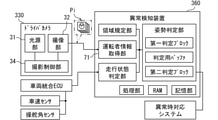
図1及び図2に示す本開示の一実施形態による状態監視システム10は、車両Aにおいて用いられ、車両Aの運転席に着座する運転者の状態を監視する。状態監視システム10は、車両Aに搭載された減速停止型の異常時対応システム90を作動させるための車載構成である。異常時対応システム90は、車両Aを停止させるまでの車線逸脱防止機能及び路外逸脱防止機能を有している。運転者が体調異常状態(所謂デッドマン)となり、運転の継続が困難となった場合、運転者の姿勢崩れが状態監視システム10によって検知される。こうした状態監視システム10のデッドマン判定に基づき、異常時対応システム90は、緊急措置として、運転者に代わって車両Aを停止させる。
The
状態監視システム10は、DSM(Driver Status Monitor)30及び異常検知装置60等によって構成されている。DSM30及び異常検知装置60は、直接的又は間接的に電気接続されており、相互に通信可能である。
The
DSM30は、撮像面を運転者の顔側へ向けた姿勢にて、ステアリングコラムの上面又はメータフード天井面等に設置されている。DSM30は、光源部31、撮像部32、撮影制御部34及び画像解析部35を備えている。
The DSM 30 is installed on the upper surface of the steering column, the ceiling surface of the meter hood, or the like with the image pickup surface facing the driver's face. The DSM 30 includes a
光源部31は、近赤外光を放射する複数の発光ダイオードを有している。光源部31は、運転席のヘッドレスト近傍へ向けて、近赤外光を照射する。撮像部32は、撮像素子及び光学系等によって構成されている。撮像部32の撮影領域40は、運転者の頭部Hdを写すように規定されている。撮影領域40は、車両Aの前後方向(z軸方向)、上下方向(y軸方向)及び幅方向(x軸方向)のそれぞれにおいて、運転に適切な姿勢(以下、「正常姿勢」)をとった運転者の頭部Hdを含むように規定された三次元の直方体状の空間である。撮像部32は、光源部31によって近赤外光を照射された運転者の頭部Hdを正面側から撮影し、運転者の顔を写した顔画像Piを生成する。撮像部32は、例えば毎秒30フレームの周期にて、撮影領域40に位置した運転者の顔画像Piを連続的に生成し、撮像した顔画像Piを画像解析部35へ向けて逐次出力する。
The
撮影制御部34は、光源部31及び撮像部32を制御する。撮影制御部34は、撮像部32の撮像タイミングに合わせて、光源部31から近赤外光を照射させる。撮影制御部34は、例えば頭部Hdの周囲に明るさに合わせて、光源部31の発光期間と撮像部32の絞り値、ISO感度及びシャッタースピード等とを調整し、画像解析に好適な顔画像Piが撮影されるよう制御する。
The
画像解析部35は、連続的に撮像された顔画像Piの画像解析により、顔の輪郭、目、及び鼻等の位置を個々の顔画像Piから抽出する。画像解析部35は、各顔画像Piから抽出した情報を用いて、頭部Hdの三次元位置と頭部Hdの姿勢角等を検出する。画像解析部35は、頭部Hdの三次元位置を示すx軸,y軸,z軸についての座標情報と、姿勢角を示すヨー角,ロール角,ピッチ角等の姿勢角情報とを、異常検知装置60へ向けて逐次出力する。加えて画像解析部35は、例えば頭部Hdが撮影領域40外に移動した場合、又は手及び布等で顔を覆った場合に、検出不可を示す出力(以下、「検出不能情報」)を、座標情報及び姿勢角情報に替えて異常検知装置60へ向けて出力する。
The
尚、座標情報において、x軸,y軸及びz軸の各座標の原点(0,0,0)は、一例として、正常姿勢をとった運転者の首の付け根部分と重なるように規定される。また姿勢角情報において、ヨー角はy軸周りの角度であり、ロール角はz軸周りの角度であり、ピッチ角はx軸周りの角度である。ヨー角,ロール角及びピッチ角は、胴体に対して頭部Hdが傾くことなく正面を向き、且つ、顔向きが水平面に沿っている場合に、それぞれ0°とされる。 In the coordinate information, the origin (0, 0, 0) of each of the x-axis, y-axis, and z-axis coordinates is defined to overlap the base of the neck of the driver in the normal posture as an example. .. Further, in the posture angle information, the yaw angle is an angle around the y-axis, the roll angle is an angle around the z-axis, and the pitch angle is an angle around the x-axis. The yaw angle, roll angle, and pitch angle are set to 0 ° when the head Hd faces the front without tilting with respect to the body and the face direction is along the horizontal plane.
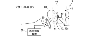
異常検知装置60は、DSM30にて撮像された顔画像Piの情報に基づき、姿勢崩れを起こしたデッドマン状態にある運転者の異常姿勢を検知する。異常検知装置60によって検知可能な異常姿勢には、例えば、突っ伏し状態(図3参照)、ずり落ち状態(図4参照)、仰け反り状態(図5参照)及び横倒れ状態(図6参照)等が含まれている。
The
具体的に、突っ伏し状態(図3参照)での頭部Hdは、正常姿勢(図1参照)よりも下向きの姿勢角(ピッチ角)で、前下方に移動している。ずり落ち状態(図4参照)での頭部Hdは、正常姿勢よりも下方に移動している。仰け反り状態(図5参照)での頭部Hdは、正常姿勢よりも上向きの姿勢角で、後下方に移動している。横倒れ状態(図6参照)での頭部Hdは、正常姿勢よりも横向きの姿勢角で、横下方に移動している。 Specifically, the head Hd in the prone state (see FIG. 3) moves forward and downward with a posture angle (pitch angle) downward from the normal posture (see FIG. 1). The head Hd in the slid-down state (see FIG. 4) moves below the normal posture. The head Hd in the leaning state (see FIG. 5) moves backward and downward with a posture angle upward from the normal posture. The head Hd in the sideways state (see FIG. 6) moves laterally downward with a posture angle sideways from the normal posture.
これらの異常姿勢を検知する異常検知装置60は、例えば車両Aに搭載された複数の電子制御ユニットのうちの一つであって、処理部61、RAM62、記憶部63及び入出力インターフェースを有するコンピュータを主体に構成されている。処理部61は、CPU(Central Processing Unit)、GPU(Graphics Processing Unit)及びFPGA(Field-Programmable Gate Array)等の少なくとも一つを含む構成である。記憶部63には、処理部61によって実行される種々のプログラムが格納されている。記憶部63に記憶された複数のプログラムには、異常検知プログラムが含まれている。異常検知プログラムは、運転者の異常姿勢を検知することにより、運転者の姿勢崩れを判定するプログラムである。異常検知装置60は、異常検知プログラムを処理部61によって実行することにより、運転者情報取得部71、走行状態判定部72、領域規定部73及び姿勢判定部74等の機能ブロックを有する。
The
運転者情報取得部71は、運転者の状態に関連する検出情報を取得する。具体的に、運転者情報取得部71は、座標情報、姿勢角情報及び検出不能情報等をDSM30から取得する。
The driver
走行状態判定部72は、一例として、車両Aに搭載された車両統合ECU(Electronic Control Unit)50から、車両Aの走行状態に関連する情報を取得する。車両統合ECU50は、例えば車速センサ51及び操舵角センサ52等と電気的に接続されている。走行状態判定部72は、走行状態を示す情報として、車速情報及びステアリング角情報等を車両統合ECU50から取得する。走行状態判定部72は、車両統合ECU50から取得した情報に基づき、車両Aの走行状態が予め規定された除外条件に該当しているか否かを判定する。
As an example, the traveling
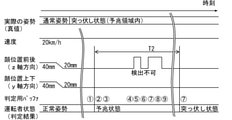
除外条件は、例えば低速で細街路を走行しているシーン等で、周囲の安全確認のために正常姿勢とは異なる姿勢をとった運転者の状態を、異常姿勢と判定されないように除外するための条件である。換言すれば、除外条件は、低速で右左折するような細街路での走行シーンを間接的に推定可能なように設定されている。走行状態判定部72は、一例として、車速が10km/h以下である場合に、除外条件に該当すると判定する。さらに、走行状態判定部72は、ステアリング角度が+60deg.を超えている場合、又は-60deg.未満である場合にも、除外条件に該当すると判定する。
The exclusion condition is to exclude the state of the driver who took a posture different from the normal posture for safety confirmation of the surroundings, for example, in a scene of driving on a narrow street at a low speed, so as not to be judged as an abnormal posture. It is a condition of. In other words, the exclusion condition is set so that the driving scene on a narrow street such as turning left or right at a low speed can be indirectly estimated. As an example, the traveling
領域規定部73は、撮影領域40の中に少なくとも一つの予兆領域42(図3~図6参照)を規定する。予兆領域42は、撮影領域40のうちで、正常姿勢から異常姿勢に遷移する過程で運転者の頭部Hdが位置すると想定される範囲に規定される。予兆領域42は、撮影領域40と同様に三次元の仮想空間であって、撮影領域40を区画する少なくとも一つの境界面44を含み、且つ、当該境界面44から前後方向、上下方向及び幅方向にそれぞれ所定の幅を有する範囲に規定されている。領域規定部73は、異常検知装置60の検知対象とされた複数種類の異常姿勢に対応する複数の予兆領域42を、個別に規定可能である。
The
詳記すると、異常姿勢毎の予兆領域42は、正常姿勢から個々の異常姿勢に移行する際に通過又は経由すると予測される空間に規定されている。具体的に、突っ伏し状態に対応する予兆領域42a(図3のドット範囲参照)は、撮影領域40の全体のうちの前下方の部分に、上下方向を長手とする直方体状に規定されている。ずり落ち状態に対応する予兆領域42b(図4のドット範囲参照)は、撮影領域40の全体のうちの後ろ下方の部分に、前後方向を長手とする直方体状に規定されている。仰け反り状態に対応する予兆領域42c(図5のドット範囲参照)は、撮影領域40の全体のうちの後方向の部分に、上下方向を長手とする直方体状に規定されている。以上の各予兆領域42a~42cは、x軸方向において、撮影領域40を区画する左右の境界面44間の全体にわたるように規定されている。
More specifically, the precursor region 42 for each abnormal posture is defined as a space that is expected to pass or pass through when transitioning from a normal posture to an individual abnormal posture. Specifically, the sign region 42a (see the dot range in FIG. 3) corresponding to the prone state is defined as a rectangular parallelepiped shape extending in the vertical direction in the front lower portion of the entire photographing
加えて、左への横倒れ状態に対応する予兆領域42d(図6のドット範囲参照)は、撮影領域40の全体のうちの左下の部分に、上下方向を長手とする直方体状に規定されている。同様に、右への横倒れ状態に対応する予兆領域42e(図6のドット範囲参照)は、撮影領域40の全体のうちの右下部分に、上下方向を長手とする直方体状に規定されている。尚、各予兆領域42d,42eは、z軸方向において、撮影領域40を区画する前後の境界面間の全体にわたるように規定されている。
In addition, the sign region 42d (see the dot range in FIG. 6) corresponding to the sideways tilted state is defined in the lower left portion of the
領域規定部73は、運転者の正常姿勢における頭部Hdの位置に基づき、予兆領域42の大きさ又は位置を調整可能であってもよい。加えて領域規定部73は、疲労軽減のため走行中にて不可避的に生じる運転者の姿勢変化に合わせて、予兆領域42の位置及びサイズを調整してもよい。
The
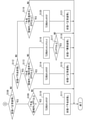
姿勢判定部74は、運転者の状態判定を、正常姿勢、予兆状態及び異常姿勢のうちで遷移させる(図7及び図8参照)。状態遷移のロジックは、正常姿勢から異常姿勢へ遷移する場合、必ず予兆状態を通過するように設定されている。換言すれば、正常姿勢から異常姿勢への直接的な状態遷移は、実施されない。姿勢判定部74は、異常検知装置60の起動により、運転者の状態を、初期値としての正常姿勢に設定する。走行状態判定部72は、運転者の頭部Hdが予兆領域42に逗留した、換言すれば、予兆領域42に頭部Hdが一定期間とどまった場合に、判定結果としての運転者の状態を、正常姿勢から予兆状態へと遷移させる。
The
さらに姿勢判定部74は、運転者の状態が予兆状態への遷移した後、正常姿勢に戻らないまま所定時間T2(例えば1.7秒)が経過した場合、判定結果としての運転者の状態を異常姿勢と判定する。一方で、予兆状態又は異常姿勢への遷移後であっても、運転者が正常姿勢に復帰した場合には、姿勢判定部74は、予兆状態又は異常姿勢から正常姿勢へと運転者の状態を遷移させる。こうした状態遷移を実施するため、姿勢判定部74には、第一判定ブロック75、判定用バッファ76及び第二判定ブロック77等のサブ機能ブロックが設けられている。
Further, the
第一判定ブロック75は、判定用バッファ76と協働で、正常姿勢から予兆状態への遷移、及び予兆状態又は異常姿勢から正常姿勢への遷移を制御する。第一判定ブロック75は、例えば一定の周期(例えば30回/秒)で、頭部Hdの位置及び姿勢角の両方に基づき、予兆領域42に頭部Hdがあるか否かの判断を繰り返す。
The
判定用バッファ76には、予兆領域42に頭部Hdがあるか否かの判断結果を格納する複数の記憶領域(キュー)が設けられている。判定用バッファ76には、所定時間T1(例えば0.66秒)分の判断結果を連続して格納可能な記憶領域が用意されている。判定用バッファ76は、第一判定ブロック75による判断結果を、時系列に沿って所定数記憶する。判定用バッファ76の各記憶領域には、具体的に、「予兆領域内」、「予兆領域外」、「除外条件中」及び「検出不可」をそれぞれ示すいずれか一つの値が格納される。判定用バッファ76は、判断結果を先入れ先出しする処理(First In, First Out,FIFO)により、一つの最新値を記憶するタイミングで、最も古い一つの値を破棄する。
The
第一判定ブロック75は、判定用バッファ76に格納された判断結果の総数のうちで、「予兆領域内」の数が占める割合に基づき、予兆領域42に頭部Hdが逗留したと判定する。具体的に、「予兆領域内」の数が、全判断結果の総数の所定割合P1(例えば90%)を超えた場合に、第一判定ブロック75は、予兆領域42に頭部Hdが逗留したと判定する。その結果、正常姿勢から予兆状態への状態遷移が行われる。
The
加えて第一判定ブロック75は、判定用バッファ76に格納された判断結果の総数のうちで、「予兆領域外」及び「除外条件中」の合計数が占める割合に基づき、正常姿勢に復帰したと判定する。具体的に、「予兆領域外」及び「除外条件中」の合計数が、第一判定ブロック75に格納された総数の所定割合P2(例えば20%)を超えた場合に、第一判定ブロック75は、正常姿勢に復帰したと判定する。その結果、予兆状態又は異常姿勢から正常姿勢への状態遷移が行われる。
In addition, the
第二判定ブロック77は、予兆状態から異常姿勢への遷移を制御する。第二判定ブロック77は、予兆状態への遷移後の経過時間を計測するカウンタ機能を有している。第二判定ブロック77は、予兆状態への状態遷移後、即ち、頭部Hdの予兆領域42への逗留後の経過時間を計測する。具体的に、第二判定ブロック77は、撮影領域40のうちで予兆領域42を除く領域(以下、「正常領域41」,図3参照)に復帰しないまま、カウンタの示す経過時間が所定時間T2を超えた場合に、予兆状態から異常姿勢への状態遷移を行う。以上により、運転者が異常姿勢の状態にあると判定される。
The
以上の状態遷移を実現する異常姿勢判定処理の詳細を、図9及び図10に基づき、図2,図3及び図7を参照しつつ説明する。図9及び図10に示す異常姿勢判定処理は、例えば車両Aのイグニッションがオン状態に切り替えられたことに基づき、異常検知装置60によって開始される。異常姿勢判定処理は、車両Aのイグニッションがオフ状態とされるまで、異常検知装置60によって繰り返される。尚、一つの異常姿勢判定処理は、一つの異常姿勢(例えば突っ伏し状態)を検知するための処理である。即ち、異常検知装置60は、検知対象とされる異常姿勢の数の分だけ、複数の異常姿勢判定処理を並行処理する。
The details of the abnormal posture determination process for realizing the above state transition will be described with reference to FIGS. 2, 3 and 7 based on FIGS. 9 and 10. The abnormal posture determination process shown in FIGS. 9 and 10 is started by the
S101では、車両Aの走行状態が除外条件に該当しているか否かを判定する。走行状態判定部72にて除外条件が成立している場合、S101からS102に進む。S102では、判定用バッファ76の最新値に「除外条件中」を示す値を格納し、S108に進む。一方、S101にて、除外条件が成立していない場合、S103に進む。
In S101, it is determined whether or not the traveling state of the vehicle A corresponds to the exclusion condition. If the exclusion condition is satisfied by the traveling
S103では、運転者情報取得部71による検出不能情報の取得の有無を判定する。S103にて、頭部Hdが検出不可状態であると判定した場合、S104に進む。S104では、判定用バッファ76の最新値に「検出不可」を示す値を格納し、S108に進む。一方、S103にて、検出不可情報の取得がと判定した場合、S105に進む。
In S103, it is determined whether or not the driver
S105では、運転者情報取得部71に提供された座標情報及び姿勢角情報に基づき、頭部Hdが予兆領域42内にあるか否かを判定する。一例として、座標情報が前後方向z>25mm且つ上下方向y>-25mmを満たし、さらに姿勢角情報がピッチ角≦0deg.を満たすとき、突っ伏し状態の予兆領域42内に頭部Hdがあると判定される。S105にて、頭部Hdが予兆領域42内にあると判定した場合、S106に進む。S106では、判定用バッファ76の最新値に「予兆領域内」を示す値を格納し、S108に進む。一方、S105にて、頭部Hdが正常領域41内にあると判定した場合、S107に進む。S107では、判定用バッファ76の最新値に「予兆領域外」を示す値を格納し、S108に進む。尚、S102,S104,S106及びS108の処理では、判定用バッファ76に格納された最も古い一つの値が破棄される。
In S105, it is determined whether or not the head Hd is in the sign region 42 based on the coordinate information and the posture angle information provided to the driver
S108では、姿勢判定部74にて判定された運転者の状態が「正常姿勢」か否かを判定する。運転者の状態が「正常姿勢」である場合、S108からS109に進む。S109では、所定時間T1内の判定用バッファ76にて「予兆領域内」を示す値の割合が、所定割合P1以上であるか否かを判定する。S109にて、「予兆領域内」を示す値の割合が所定割合P1未満である場合、異常姿勢判定処理を一旦終了する。一方で、S109にて、「予兆領域内」を示す値の割合が所定割合P1以上である場合、S110に進む。
In S108, it is determined whether or not the state of the driver determined by the
S110では、第二判定ブロック77に設けられたカウンタ(以下、「T2用カウンタ」)の値をクリアし、S111に進む。S111では、運転者の状態を、「正常姿勢」から「予兆状態」へと遷移させ、異常姿勢判定処理を一旦終了する。 In S110, the value of the counter provided in the second determination block 77 (hereinafter, “counter for T2”) is cleared, and the process proceeds to S111. In S111, the driver's state is changed from the "normal posture" to the "predictive state", and the abnormal posture determination process is temporarily terminated.
S108にて、運転者の状態が「正常姿勢」でないと判定した場合、S112に進む。S112では、運転者の遷移状態が「予兆状態」か否かを判定する。S112にて、運転者の状態が「予兆状態」である場合、S113に進む。S113では、所定時間T1内の判定用バッファ76にて「予兆領域外」及び「除外条件中」を示す各値の合計数が、所定割合P2以上であるか否かを判定する。S113にて、「予兆領域外」及び「除外条件中」の合計数が所定割合P2以上である場合、S114に進む。S114では、S110と同様にT2用カウンタの値をクリアし、S115に進む。S115では、運転者の状態を「予兆状態」から「正常姿勢」へと遷移させ、異常姿勢判定処理を一旦終了する。
If it is determined in S108 that the state of the driver is not the "normal posture", the process proceeds to S112. In S112, it is determined whether or not the transition state of the driver is a “predictive state”. If the driver's state is the "predictive state" in S112, the process proceeds to S113. In S113, it is determined whether or not the total number of the values indicating "outside the sign region" and "in the exclusion condition" in the
S113にて、「予兆領域外」及び「除外条件中」の合計数が所定割合P2未満である場合、S116に進む。S116では、T2用カウンタの値をインクリメントし、S117に進む。S117では、T2用カウンタの示す経過時間が所定時間T2以上か否かを判定する。S117にて、経過時間が所定時間T2未満であると判定した場合、異常姿勢判定処理を一旦終了する。一方で、S117にて、所定時間T2以上の時間経過があったと判定した場合、S118に進む。S118では、運転者の状態を「予兆状態」から「異常姿勢」へと遷移させ、異常姿勢判定処理を一旦終了する。 In S113, when the total number of “outside the sign area” and “under exclusion condition” is less than the predetermined ratio P2, the process proceeds to S116. In S116, the value of the T2 counter is incremented, and the process proceeds to S117. In S117, it is determined whether or not the elapsed time indicated by the T2 counter is T2 or more for a predetermined time. If it is determined in S117 that the elapsed time is less than the predetermined time T2, the abnormal posture determination process is temporarily terminated. On the other hand, if it is determined in S117 that the predetermined time T2 or more has elapsed, the process proceeds to S118. In S118, the driver's state is changed from the “predictive state” to the “abnormal posture”, and the abnormal posture determination process is temporarily terminated.
さらに、S112にて運転者の状態が「予兆状態」でないと判定した場合、S119に進む。S119では、S113と同様に、所定時間T1内の判定用バッファ76にて「予兆領域外」及び「除外条件中」を示す各値の合計数が、所定割合P2以上であるか否かを判定する。S119にて、「予兆領域外」及び「除外条件中」の合計数が所定割合P2以上である場合、S120に進む。S120では、T2用カウンタの値をクリアし、S121に進む。S121では、運転者の状態を「異常姿勢」から「正常姿勢」へと遷移させ、異常姿勢判定処理を一旦終了する。一方で、S119にて、「予兆領域外」及び「除外条件中」を示す各値の合計数が所定割合P2未満である場合、異常姿勢判定処理を一旦終了する。
Further, when it is determined in S112 that the state of the driver is not the "predictive state", the process proceeds to S119. In S119, as in S113, it is determined in the
ここまで説明した異常判定処理による運転者の状態遷移の具体例を、図11~図26に示すユースケース1~8に基づいて、図2及び図3を参照しつつ、順に説明する。尚、以下の説明では、異常姿勢としての突っ伏し状態が運転者に生じた場合を例に説明する。また、所定時間T1,T2及び所定割合P1,P2は、それぞれ上記に例示した値、即ち、0.66秒,1.7秒,90%,20%を使用する。
Specific examples of the driver's state transition by the abnormality determination process described so far will be described in order with reference to FIGS. 2 and 3 based on the
<ユースケース1>
図11及び図12に示すユースケース1は、運転者の姿勢が正常な状態に維持された場合である。この場合、例えば手で顔を覆う等の能動的な行為又はノイズ等の発生により、判定用バッファ76には、「予兆領域外」の判断結果だけでなく、「検出不可」の判断結果も格納される。しかし、ユースケース1では、運転者の正常姿勢が維持されているため、「予兆領域内」を示す判断結果の割合は、判定用バッファ76の総数の所定割合P1を超えない。故に、姿勢判定部74は、運転者の状態を「正常姿勢」であると判定し続ける。
<Use
The
<ユースケース2>
図13及び図14に示すユースケース2は、一時的に突っ伏し状態となり、その後、通常姿勢に復帰した場合である。通常姿勢は、運転に望ましい正常姿勢に加えて、僅かに大勢を変化させた状態も含んでいる。この場合、運転者が突っ伏し状態へ遷移したことにより、判定用バッファ76には、「予兆領域内」の判断結果が格納される。しかし、「予兆領域内」を示す判断結果の割合が所定割合P1を超える前に、運転者は、突っ伏し状態から復帰している。故に、判定用バッファ76には、「予兆領域外」の判断結果が再び格納される。その結果、姿勢判定部74は、運転者の状態を「予兆状態」に遷移させることなく、「正常姿勢」であると判定し続ける。
<Use
The
<ユースケース3>
図15及び図16に示すユースケース3は、ユースケース2よりも長い一定時間だけ突っ伏し状態(図3参照)となり、そのあと通常姿勢に復帰した場合である。具体例としては、運転者がくしゃみ等をした場合である。この場合、運転者が突っ伏し状態へ遷移したことにより、判定用バッファ76には、「予兆領域内」の判断結果が格納される。突っ伏し状態の継続により、判定用バッファ76に占める「予兆領域内」の判断結果の割合が所定割合P1を超えたタイミング(時刻2)で、姿勢判定部74は、運転者の状態を「正常姿勢」から「予兆状態」に遷移させる。
<Use
The
一方で、「予兆状態」への遷移後に、運転者は通常姿勢に復帰している。その結果、判定用バッファ76には、「予兆領域外」の判断結果が再び格納されるようになる。そして、「予兆領域外」を示す判断結果の割合が所定割合P2を超えたタイミング(時刻8)で、姿勢判定部74は、運転者の状態を「予兆状態」から「正常姿勢」に復帰させる。以上のように、所定時間T2の経過前に通常姿勢への復帰があれば、異常姿勢の確定判定は、実施されなくてよい。
On the other hand, after the transition to the "predictive state", the driver has returned to the normal posture. As a result, the determination result of "outside the sign region" is stored again in the
<ユースケース4>
図17及び図18に示すユースケース4は、右折等の実施に際して、突っ伏し状態に近い右折姿勢を運転者がとった場合である。この場合、例えば右折のための一時的な減速により、走行状態判定部72にて除外条件が成立する。仮に、右折姿勢をとった運転者の頭部Hdが予兆領域42aにあったとしても、姿勢判定部74は、「予兆領域内」とは判断せず、「除外条件中」と判断する。こうして判定用バッファ76には、「除外条件中」の判断結果が連続的に格納される。その結果、「予兆領域内」を示す判断結果の割合が所定割合P1を超えないため、姿勢判定部74は、右折姿勢を突っ伏し状態と誤認することなく、運転者の状態を「正常姿勢」であると判定し続ける。
<Use
The
<ユースケース5>
図19及び図20に示すユースケース5は、ユースケース4と同様に、右折のシーンを想定したユースケースであり、突っ伏し状態に近い右折姿勢を運転者がとった場合である。但し、ユースケース5の運転者は、除外条件の成立していない走行状態で右折姿勢をとっている。故に、判定用バッファ76には「予兆領域内」の判断結果が格納されるようになる。そのため、右折姿勢の継続により、判定用バッファ76に占める「予兆領域内」の判断結果の割合が所定割合P1を超えたタイミング(時刻2)で、姿勢判定部74は、運転者の状態を「正常姿勢」から「予兆状態」に遷移させる。
<Use
Similar to the
しかし、「予兆状態」への遷移後に除外条件が成立するため、判定用バッファ76には、「予兆領域内」に替えて、「除外条件中」の判断結果が連続的に格納されるようになる。その結果、「除外条件中」を示す判断結果の割合が所定割合P2を超えたタイミング(時刻8)で、姿勢判定部74は、運転者の状態を「予兆状態」から「正常姿勢」に復帰させる。
However, since the exclusion condition is satisfied after the transition to the "predictive state", the judgment result of "in the exclusion condition" is continuously stored in the
以上のように、姿勢判定部74は、右折姿勢等を突っ伏し状態と誤認知し、「予兆状態」への遷移を実施し得る。しかし、姿勢判定部74は、除外条件の成立後に、運転者の状態を「正常姿勢」と正しく再判定できる。即ち、右折姿勢等に起因して「異常姿勢(突っ伏し状態)」と誤判定する事態は、回避される。
As described above, the
<ユースケース6>
図21及び図22に示すユースケース6の運転者は、突っ伏し状態(図3参照)となった後、さらに撮影領域40外に倒れ込んでいる。この場合、運転者の突っ伏し状態への遷移により、判定用バッファ76には、「予兆領域内」の判断結果が格納される。そして、判定用バッファ76に占める「予兆領域内」の判断結果の割合が所定割合P1を超えたタイミング(時刻2)で、姿勢判定部74は、運転者の状態を「正常姿勢」から「予兆状態」に遷移させる。
<Use
The driver of the
さらに、運転者の頭部Hdが撮影領域40外に倒れ込むことにより、判定用バッファ76には、「検出不可」の判断結果が格納され始める(時刻5)。「検知不可」の判断結果が格納されたとしても、「予兆領域外」及び「除外条件中」の合計数が所定割合P2を超えないため、姿勢判定部74は、「正常姿勢」への状態遷移を行うことなく、「予兆状態」の判定を維持する。
Further, when the driver's head Hd falls out of the photographing
そして、運転者の通常姿勢への復帰により、頭部Hdが撮影領域40の外から正常領域41に戻されると、判定用バッファ76には、再び「予兆領域外」の判断結果が格納される(時刻13)。「予兆状態」への遷移後、所定時間T2の経過前に、「予兆領域外」及び「除外条件中」の合計数が所定割合P2を超えれば、姿勢判定部74は、運転者の状態を再び「正常姿勢」と判定するようになる(時刻16)。
Then, when the head Hd is returned from the outside of the photographing
<ユースケース7>
図23及び図24に示すユースケース7は、運転者の姿勢が突っ伏し状態のまま固着した場合である。この場合でも、判定用バッファ76に占める「予兆領域内」の判断結果の割合が所定割合P1を超えたタイミング(時刻2)で、姿勢判定部74は、運転者の状態を「正常姿勢」から「予兆状態」に遷移させる。
<Use
The
突っ伏した状態の運転者の頭部Hdは、例えば撮影領域40の境界面44近傍で車両Aの走行振動等によって揺れるような動きをする。故に、判定用バッファ76には、散発的に「検出不可」が格納される。しかし、こうしたノイズがあったとしても、「予兆領域外」及び「除外条件中」の合計数は、所定割合P2を超えないままとなる。その結果、「予兆状態」の状態判定は、維持される。そして、「予兆状態」への遷移後に所定時間T2が経過するタイミング(時刻10)で、姿勢判定部74は、運転者の状態を「突っ伏し状態」であると判定できる。
The driver's head Hd in the prone state moves, for example, in the vicinity of the
<ユースケース8>
図25及び図26に示すユースケース8の運転者は、ユースケース6と同様に、突っ伏し状態(図3参照)となった後に、さらに撮影領域40の領域外に倒れ込んでいる。ユースケース8の運転者は、撮影領域40からフレームアウトしたまま、復帰しない。この場合でも、ユースケース7と同様に、判定用バッファ76に占める「予兆領域内」の判断結果の割合が所定割合P1を超えたタイミング(時刻2参照)で、姿勢判定部74は、運転者の状態を「正常姿勢」から「予兆状態」に遷移させる。
<Use
Similar to use
そして、運転者の頭部Hdが撮影領域40からフレームアウトした後、運転者情報取得部71に検出不可情報が提供されるようになると、判定用バッファ76には、「検出不可」の判断結果が格納され続ける。この場合でも、「予兆領域外」及び「除外条件中」の合計数が所定割合P2を超えないため、運転者の状態は、「正常状態」に遷移せず、「予兆状態」のまま維持される。その後、「予兆領域外」及び「除外条件中」の合計数が所定割合P2を超えないまま所定時間T2が経過するタイミング(時刻8)で、姿勢判定部74は、運転者の状態を「突っ伏し状態」であると判定する。
Then, when the undetectable information is provided to the driver
ここまで説明した本実施形態では、正常姿勢から異常姿勢に遷移する過程で運転者の頭部Hdが位置すると想定される範囲に、予兆領域42が規定されている。そして、予兆領域42に頭部Hdが逗留した場合に、異常姿勢との判定が行われる。このように、姿勢判定部74は、異常姿勢の判定に、撮影領域40の境界面44付近或いは領域外の情報だけではなく、撮影領域40内に規定された予兆領域42の情報を用いることができる。
In the present embodiment described so far, the sign region 42 is defined in the range where the driver's head Hd is assumed to be located in the process of transitioning from the normal posture to the abnormal posture. Then, when the head Hd stays in the sign region 42, it is determined that the posture is abnormal. As described above, the
こうした予兆領域42の情報の精度は、撮影領域40からの頭部Hdのフレームアウトを根拠に姿勢崩れを判定する従来技術にて用いられる撮影領域40の境界上又は境界のごく近傍、或いは撮影領域外の各情報の精度よりも確保容易である。詳記すると、頭部Hdが撮影領域40からフレームアウトしかけている場合、顔画像における運転者の顔は、撮影領域40の境界付近に僅かに写るのみとなる。また、頭部Hdが撮影領域40からフレームアウトしている場合、顔画像には、運転者が写らない。これらのように、従来技術で用いられる顔画像は、正面から顔をとらえた画像とはなり難く、且つ、顔の撮影面積も確保困難となる。その結果、撮影領域40の境界付近或いは領域外の情報精度は、当然に確保困難となる。
The accuracy of the information in the precursor region 42 is on or near the boundary of the
一方で、撮影領域40の一部に規定した予兆領域42に頭部Hdが位置する段階では、顔画像Piは、正面から顔をとらえた画像にもなり得るうえ、顔の撮影面積も確保され易い。そのため、予兆領域42の情報精度は、フレームアウトのごく直前の境界面44付近の情報精度、及びフレームアウト以後である領域外の情報精度よりも、確保され易い。以上の理由により、予兆領域42の情報を用いた異常姿勢の判定では、運転者の姿勢崩れについての判定精度が向上可能となる。
On the other hand, at the stage where the head Hd is located in the sign area 42 defined as a part of the photographing
加えて、デッドマン状態となった運転者の頭部Hdが例えば境界面44を跨ぐようにして不規則に揺れた場合、頭部Hdの移動軌跡を追跡する比較形態では、正常姿勢に戻ろうとする頭部Hdの動きに基づき、異常姿勢と判定されない場合がある。対して本実施形態では、揺れた頭部Hdが予兆領域42への出入りを繰り返しても、姿勢判定部74は、予兆領域42に頭部Hdがあった累積時間を鑑みて、予兆領域42への逗留判定、ひいては異常姿勢の判定を行うことができる。故に、予兆領域42への逗留を用いた異常姿勢の判定は、頭部Hdの移動軌跡を用いた判定と比較しても、運転者の姿勢崩れを精度良く抽出できる。
In addition, when the head Hd of the driver in the deadman state sways irregularly, for example, straddling the
また本実施形態の姿勢判定部74は、予兆領域42への逗留後、頭部Hdが正常領域41に戻らない場合に、運転者が異常姿勢にあると判定する。このように、運転者の姿勢崩れを予兆領域42への頭部Hdの逗留によって予備判定したうえで、姿勢崩れの継続に基づいて異常姿勢の確定判定を行う手法であれば、異常姿勢の誤判定がいっそう低減可能となる。
Further, the
さらに本実施形態では、頭部Hdの位置及び姿勢角の両方に基づき、予兆領域42への頭部Hdの逗留が判定される。以上のように、頭部Hdの位置及び姿勢角の両方を用いれば、姿勢判定部74は、異常に起因した予兆領域42への頭部Hdの逗留を、正常状態にある運転者の単なる姿勢変化と精度良く区別し得る。したがって、予兆領域42への逗留を利用した異常姿勢の判定の精度は、いっそう向上可能になる。
Further, in the present embodiment, the retention of the head Hd in the sign region 42 is determined based on both the position of the head Hd and the posture angle. As described above, if both the position and the posture angle of the head Hd are used, the
加えて本実施形態の予兆領域42は、撮影領域40の境界面44から所定の幅を有するように規定されている。こうした予兆領域42の設定であれば、検出精度の確保が困難になり易い境界面44だけでなく、検出精度の確保が見込める範囲も、予兆領域42には含まれる。その結果、予兆領域42への頭部Hdの逗留を判定する精度が、さらに確保され易くなる。
In addition, the precursor region 42 of the present embodiment is defined to have a predetermined width from the
また本実施形態の撮影領域40は、頭部Hdを含むような三次元空間である。加えて、予兆領域42も、撮影領域40の中に規定された三次元の空間である。以上のように、撮影領域40及び予兆領域42を共に三次元で規定すれば、予兆領域42は、異常姿勢を生じた運転者の頭部Hdがあるはずの位置に、適確に規定され得る。その結果、姿勢判定部74は、異常に伴う運転者の姿勢崩れを精度良く検知可能となる。
Further, the photographing
さらに本実施形態では、複数種類の異常姿勢に対応する複数の予兆領域42a~42eが個別に規定されている。そして、運転者が正常姿勢に復帰しない場合、姿勢判定部74は、頭部Hdの逗留があった予兆領域42に対応する種類の異常姿勢を判定する。このように、各異常姿勢へ遷移する過程で通過するであろう予兆領域42が個別に設定されていれば、姿勢判定部74は、複数種類の異常姿勢を判定できる。その結果、異常に伴う運転者の姿勢崩れの検知漏れが低減可能となる。
Further, in the present embodiment, a plurality of predictive regions 42a to 42e corresponding to a plurality of types of abnormal postures are individually defined. Then, when the driver does not return to the normal posture, the
加えて本実施形態では、走行状態についての除外条件が成立している場合、姿勢判定部74は、予兆領域42に頭部Hdがあると判断しない。こうした除外条件の採用によれば、姿勢判定部74は、姿勢崩れに伴う頭部Hdの移動と、周辺確認等のための運転者の動作等とを区別できる。したがって、通常の運転動作に伴う右折姿勢等が異常姿勢と誤判定される事態は、防止され得る。
In addition, in the present embodiment, when the exclusion condition for the traveling state is satisfied, the
また本実施形態の姿勢判定部74は、判定用バッファ76に格納された判定結果の割合を用いて、予兆領域42への頭部Hdの逗留を判定する。こうした判定ロジックの採用によれば、ノイズ等の影響による逗留判定の誤りが低減可能になる。
Further, the
尚、第一実施形態では、正常領域41が「特定領域」に相当し、境界面44が「境界」に相当し、判定用バッファ76が「バッファ部」に相当し、顔画像Piが「画像」に相当する。
In the first embodiment, the
(他の実施形態)
以上、本開示による一実施形態について説明したが、本開示は、上記実施形態に限定して解釈されるものではなく、本開示の要旨を逸脱しない範囲内において種々の実施形態及び組み合わせに適用することができる。
(Other embodiments)
Although the embodiment according to the present disclosure has been described above, the present disclosure is not construed as being limited to the above embodiment, and is applied to various embodiments and combinations within the scope of the gist of the present disclosure. be able to.
上記実施形態による状態監視システム10は、DSM30及び異常検知装置60を含む構成であった(図2参照)。しかし、本開示による異常検知装置の機能は、種々の形態で提供されてよい。例えば、図27に示す上記実施形態の変形例1では、異常検知装置の機能がDSM230に内蔵されている。詳記すると、変形例1では、DSM230の処理部61が、記憶部63に記憶された異常検知プログラムを実行可能である。その結果、DSM230は、撮影制御部34、画像解析部35、運転者情報取得部71、走行状態判定部72、領域規定部73及び姿勢判定部74等の機能ブロックを有する。こうした変形例1でも、上記実施形態と同様の効果を奏する。尚、変形例1では、DSM230が「異常検知装置」に相当する。
The
さらに、図28に示す上記実施形態の変形例2では、異常検知装置360が、ドライバカメラ330と接続されている。ドライバカメラ330は、光源部31、撮像部32及び撮影制御部34を含む構成であり、連続的に撮影した顔画像Piを異常検知装置360に提供する。異常検知装置360の運転者情報取得部71は、上記実施形態の画像解析部35(図2参照)と実質同一の画像解析機能をさらに有しており、各顔画像Piから抽出した情報を用いて、頭部の三次元での座標位置と頭部の姿勢角等を検出可能である。こうした変形例2でも、上記実施形態と同様の効果を奏する。尚、顔画像Piの解析によれば、頭部Hdの位置や顔向きだけでなく、運転者の視線方向及び目の開き具合等の情報がさらに取得されてよい。
Further, in the second modification of the above embodiment shown in FIG. 28, the
上記実施形態によれば、DSMのコストアップを伴う広角側への画角拡大を伴うことなく、判定精度の向上が可能になる。しかし、DSMに採用される撮像部の画角は、広角側に拡大されてよい。予兆領域の逗留判定を用いた異常姿勢の判定は、同一画角の顔画像の情報を用いた場合において、予兆領域の逗留判定を用いない異常姿勢の判定よりも、高い判定精度を確保できる。 According to the above embodiment, it is possible to improve the determination accuracy without enlarging the angle of view to the wide-angle side, which is accompanied by an increase in the cost of the DSM. However, the angle of view of the imaging unit used in the DSM may be expanded to the wide-angle side. When the information of the face image having the same angle of view is used, the determination of the abnormal posture using the retention determination in the predictive region can secure higher determination accuracy than the determination of the abnormal posture using the retention determination in the precursor region.
さらに、DSMの設置位置は、適宜変更されてよい。ここで、DSMの設置位置が正面からずれている場合、撮影領域の境界面近傍の検出精度は、いっそう悪化し易い。故に、予兆領域への逗留判定を用いて異常姿勢を判定する処理は、DSMの設置位置が運転者の正面以外に制限される場合において、判定精度の向上にさらに寄与できる。 Further, the installation position of the DSM may be changed as appropriate. Here, when the installation position of the DSM is deviated from the front, the detection accuracy in the vicinity of the boundary surface of the photographing region is likely to be further deteriorated. Therefore, the process of determining the abnormal posture by using the determination of staying in the sign region can further contribute to the improvement of the determination accuracy when the installation position of the DSM is limited to other than the front of the driver.
上記実施形態の撮影領域及び予兆領域は、共に三次元の直方体状に規定されていた。しかし、撮影領域及び予兆領域の三次元形状は、適宜変更されてよい。撮影領域の各境界面は、僅かに湾曲していてもよく、xy平面,yz平面,zx平面のいずれかに対して傾斜していてもよい。さらに、予兆領域への進入を判断する境界面と、予兆領域から正常領域への復帰を判断する境界面とは、互いに異なっていてもよい。即ち、進入側の境界面は、復帰側の境界面よりも、撮影領域の境界面に近い位置に規定されていてもよい。さらに、撮影領域及び予兆領域は、例えば顔画像に沿う方向に二次元で規定されてもよい。この場合の境界は、一次元の線状に規定される。 Both the photographing area and the sign area of the above-described embodiment are defined in a three-dimensional rectangular parallelepiped shape. However, the three-dimensional shapes of the photographing area and the sign area may be changed as appropriate. Each boundary surface of the photographing region may be slightly curved, or may be inclined with respect to any one of the xy plane, the yz plane, and the zx plane. Further, the boundary surface for determining the entry into the precursory region and the boundary surface for determining the return from the precursory region to the normal region may be different from each other. That is, the boundary surface on the approach side may be defined at a position closer to the boundary surface of the photographing region than the boundary surface on the return side. Further, the photographing area and the sign area may be defined in two dimensions in a direction along the face image, for example. The boundary in this case is defined by a one-dimensional linear shape.
また上記実施形態では、一つの異常姿勢に対して一つの予兆領域が規定されていた。しかし、一つの異常姿勢に対して複数の予兆領域が規定されてもよい。さらに、座標情報における原点の位置は、適宜変更されてよい。例えば、撮影領域の特定の頂点が原点とされてもよい。加えて、正常領域は、撮影領域のうちで予兆領域を除いた領域の全部であってもよく、又は撮影領域のうちで予兆領域と重複しない領域の一部であってもよい。 Further, in the above embodiment, one sign area is defined for one abnormal posture. However, a plurality of predictive regions may be defined for one abnormal posture. Further, the position of the origin in the coordinate information may be changed as appropriate. For example, a specific vertex in the shooting area may be the origin. In addition, the normal region may be the entire region of the photographing region excluding the precursor region, or may be a part of the region of the imaging region that does not overlap with the precursor region.
上記実施形態における所定時間T1,T2及び所定割合P1,P2の各値は、適宜変更可能である。所定時間T1,T2及び所定割合P1,P2は、異常姿勢毎に異なる値とされていてもよい。但し、所定時間T2は、所定時間T1よりも長い時間であることが望ましい。また、所定割合P1は、所定割合P2よりも大きい値とされることが望ましい。 Each value of the predetermined time T1 and T2 and the predetermined ratio P1 and P2 in the above embodiment can be appropriately changed. The predetermined time T1 and T2 and the predetermined ratios P1 and P2 may have different values for each abnormal posture. However, it is desirable that the predetermined time T2 is longer than the predetermined time T1. Further, it is desirable that the predetermined ratio P1 is a value larger than the predetermined ratio P2.
上記実施形態では、「予兆領域外」の判断結果が所定割合P1を超えると、「正常姿勢」から「予兆状態」への状態遷移が実施された。しかし、姿勢判定部は、「予兆領域外」及び「除外条件」の合計数が所定割合P1を超えると、「正常姿勢」から「予兆状態」への状態遷移を実施してもよい。 In the above embodiment, when the judgment result of "outside the sign region" exceeds the predetermined ratio P1, the state transition from the "normal posture" to the "predict state" is carried out. However, when the total number of "outside the sign region" and "exclusion condition" exceeds the predetermined ratio P1, the posture determination unit may carry out a state transition from the "normal posture" to the "predictive state".
上記実施形態では、判定用バッファを用いた予備判定とT2用カウンタを用いた確定判定とが組み合わされていた。しかし、「予兆状態」の予備判定にカウンタが用いられてもよく、「異常姿勢」の確定判定に判定用バッファが用いられてもよい。さらに、予備判定及び確定判定の両方が、カウンタを用いて判定されてもよい。或いは、予備判定及び確定判定の両方が、判定用バッファを用いて判定されてもよい。 In the above embodiment, the preliminary determination using the determination buffer and the definite determination using the T2 counter are combined. However, a counter may be used for the preliminary determination of the "predictive state", or a determination buffer may be used for the determination determination of the "abnormal posture". Further, both the preliminary determination and the definite determination may be determined using a counter. Alternatively, both the preliminary determination and the definite determination may be determined using the determination buffer.
上記実施形態では、複数の予兆領域が規定され、複数の異常姿勢が検出可能とされていた。しかし、異常検知装置は、特定の一つの異常姿勢を検出する構成であってもよい。さらに、異常検知装置は、上記実施形態で例示した姿勢とは異なる異常姿勢を検知可能であってもよい。 In the above embodiment, a plurality of sign areas are defined, and a plurality of abnormal postures can be detected. However, the abnormality detection device may be configured to detect one specific abnormal posture. Further, the abnormality detecting device may be able to detect an abnormal posture different from the posture exemplified in the above embodiment.
上記実施形態では、右折姿勢等を誤検知しないように、除外条件が設定されていた。こうした除外条件の具体的な内容は、適宜変更されてよい。さらに、除外条件の設定は、省略されてもよい。 In the above embodiment, exclusion conditions are set so as not to erroneously detect a right turn posture or the like. The specific contents of these exclusion conditions may be changed as appropriate. Further, the setting of the exclusion condition may be omitted.
異常検知装置及びDSMの記憶部には、フラッシュメモリ及びハードディスク等の種々の非遷移的実体的記憶媒体(non-transitory tangible storage medium)が採用可能である。加えて、異常検知プログラムを記憶する記憶媒体は、車載される各構成の記憶媒体に限定されず、当該記憶媒体へのコピー元となる光学ディスク及び汎用コンピュータのハードディスクドライブ等であってもよい。 Various non-transitory tangible storage media such as flash memory and hard disk can be adopted for the storage unit of the abnormality detection device and the DSM. In addition, the storage medium for storing the abnormality detection program is not limited to the storage medium having each configuration mounted on the vehicle, and may be an optical disk as a copy source to the storage medium, a hard disk drive of a general-purpose computer, or the like.
A 車両、Hd 頭部、P1 所定割合、Pi 顔画像(画像)、230 DSM(異常検知装置)、32 撮像部、40 撮影領域、41 正常領域(特定領域)、42,42a~42e 予兆領域、44 境界面(境界)、60,360 異常検知装置、61 処理部、72 走行状態判定部、73 領域規定部、74 姿勢判定部、76 判定用バッファ(バッファ部) A vehicle, Hd head, P1 predetermined ratio, Pi face image (image), 230 DSM (anomaly detection device), 32 imaging unit, 40 shooting area, 41 normal area (specific area), 42, 42a to 42e predictive area, 44 Boundary surface (boundary), 60, 360 Anomaly detection device, 61 Processing unit, 72 Driving state determination unit, 73 Area regulation unit, 74 Attitude determination unit, 76 Judgment buffer (buffer unit)
Claims (9)
前記撮影領域のうちで、前記運転者の姿勢崩れにより、正常姿勢から前記異常姿勢に遷移する過程で前記頭部が位置すると想定される範囲に、少なくとも一つの予兆領域(42)を規定する領域規定部(73)と、
前記予兆領域に前記頭部があるか否かを判断し、前記予兆領域に前記頭部が逗留した場合に、前記運転者が前記異常姿勢の状態にあると判定する姿勢判定部(74)と、
を備える異常検知装置。 Based on the information of the image (Pi) captured by the image pickup unit in the vehicle (A) having the image pickup unit (32) in which the image pickup region (40) is defined so as to capture the driver's head (Hd). An abnormality detection device that detects the driver's abnormal posture.
In the imaging region, at least one predictive region (42) is defined in a range in which the head is assumed to be located in the process of transitioning from the normal posture to the abnormal posture due to the posture collapse of the driver. Regulation part (73) and
With the posture determination unit (74), which determines whether or not the head is in the sign region, and determines that the driver is in the abnormal posture when the head stays in the sign region. ,
Anomaly detection device equipped with.
前記領域規定部は、前記撮影領域の中に三次元の前記予兆領域を規定する請求項1~4のいずれか一項に記載の異常検知装置。 The photographing area is a three-dimensional space defined to include the head.
The abnormality detection device according to any one of claims 1 to 4, wherein the area defining unit defines a three-dimensional precursor region in the photographing region.
前記姿勢判定部は、複数の前記予兆領域のうちの一つに前記頭部が逗留した場合に、前記頭部の逗留があった前記予兆領域に対応する種類の前記異常姿勢であると判定する請求項1~5のいずれか一項に記載の異常検知装置。 The area defining unit individually defines a plurality of the sign areas corresponding to the plurality of types of the abnormal postures.
When the head stays in one of the plurality of predictive regions, the posture determination unit determines that the posture is an abnormal posture of the type corresponding to the predictive region in which the head stays. The abnormality detection device according to any one of claims 1 to 5.
前記姿勢判定部は、前記走行状態判定部にて前記除外条件が成立している場合に、前記予兆領域に前記頭部があると判断しない請求項1~6のいずれか一項に記載の異常検知装置。 Further, a traveling state determination unit (72) for determining whether or not the traveling state of the vehicle corresponds to a predetermined exclusion condition is provided.
The abnormality according to any one of claims 1 to 6, wherein the posture determination unit does not determine that the head is in the sign region when the exclusion condition is satisfied by the traveling state determination unit. Detection device.
前記姿勢判定部は、前記予兆領域に前記頭部があることを示す前記判断結果の数が前記バッファ部に記憶された前記判断結果の総数の所定割合(P1)を超えた場合に、前記予兆領域に前記頭部が逗留したと判定する請求項1~7のいずれか一項に記載の異常検知装置。 Further, a buffer unit (76) for storing a predetermined number of determination results of whether or not the head is in the sign region in chronological order is provided.
When the number of the judgment results indicating that the head is in the sign region exceeds a predetermined ratio (P1) of the total number of the judgment results stored in the buffer unit, the posture determination unit determines the sign. The abnormality detection device according to any one of claims 1 to 7, wherein it is determined that the head has stayed in the region.
少なくとも一つの処理部(61)を、
前記撮影領域のうちで、前記運転者の姿勢崩れにより、正常姿勢から前記異常姿勢に遷移する過程で前記頭部が位置すると想定される範囲に、少なくとも一つの予兆領域(42)を規定する領域規定部(73)と、
前記予兆領域に前記頭部があるか否かを判断し、前記予兆領域に前記頭部が逗留した場合に、前記運転者が前記異常姿勢の状態にあると判定する姿勢判定部(74)として機能させる異常検知プログラム。 Based on the information of the image (Pi) captured by the image pickup unit in the vehicle (A) having the image pickup unit (32) in which the image pickup region (40) is defined so as to capture the driver's head (Hd). , An abnormality detection program that detects the driver's abnormal posture.
At least one processing unit (61)
In the imaging region, at least one predictive region (42) is defined in a range in which the head is assumed to be located in the process of transitioning from the normal posture to the abnormal posture due to the posture collapse of the driver. Regulation part (73) and
As a posture determination unit (74) that determines whether or not the head is in the sign region and determines that the driver is in the abnormal posture when the head stays in the sign region. Anomaly detection program to function.
Priority Applications (3)
| Application Number | Priority Date | Filing Date | Title |
|---|---|---|---|
| JP2017236224A JP7003612B2 (en) | 2017-12-08 | 2017-12-08 | Anomaly detection device and anomaly detection program |
| PCT/JP2018/042780 WO2019111696A1 (en) | 2017-12-08 | 2018-11-20 | Abnormality detection device and abnormality detection program |
| US16/891,532 US11615632B2 (en) | 2017-12-08 | 2020-06-03 | Abnormality detection device and abnormality detection program |
Applications Claiming Priority (1)
| Application Number | Priority Date | Filing Date | Title |
|---|---|---|---|
| JP2017236224A JP7003612B2 (en) | 2017-12-08 | 2017-12-08 | Anomaly detection device and anomaly detection program |
Publications (3)
| Publication Number | Publication Date |
|---|---|
| JP2019105872A JP2019105872A (en) | 2019-06-27 |
| JP2019105872A5 JP2019105872A5 (en) | 2020-03-05 |
| JP7003612B2 true JP7003612B2 (en) | 2022-01-20 |
Family
ID=66750922
Family Applications (1)
| Application Number | Title | Priority Date | Filing Date |
|---|---|---|---|
| JP2017236224A Active JP7003612B2 (en) | 2017-12-08 | 2017-12-08 | Anomaly detection device and anomaly detection program |
Country Status (3)
| Country | Link |
|---|---|
| US (1) | US11615632B2 (en) |
| JP (1) | JP7003612B2 (en) |
| WO (1) | WO2019111696A1 (en) |
Families Citing this family (15)
| Publication number | Priority date | Publication date | Assignee | Title |
|---|---|---|---|---|
| JP6848912B2 (en) | 2018-03-23 | 2021-03-24 | 株式会社デンソー | Status determination device, status determination program and computer readable continuous tangible recording medium |
| US11417122B2 (en) * | 2018-11-21 | 2022-08-16 | Lg Electronics Inc. | Method for monitoring an occupant and a device therefor |
| US11823468B2 (en) * | 2019-11-19 | 2023-11-21 | Hyundai Mobis Co., Ltd. | Driver state warning system and method of monitoring driver state |
| JP7314085B2 (en) * | 2020-03-18 | 2023-07-25 | 株式会社東海理化電機製作所 | Image processing device, computer program, and anomaly estimation system |
| JP7314084B2 (en) * | 2020-03-18 | 2023-07-25 | 株式会社東海理化電機製作所 | Image processing device, computer program, and anomaly estimation system |
| JP7458216B2 (en) * | 2020-03-18 | 2024-03-29 | 株式会社東海理化電機製作所 | Image processing device, computer program, and abnormality estimation system |
| JP7351253B2 (en) * | 2020-03-31 | 2023-09-27 | いすゞ自動車株式会社 | Approval/refusal decision device |
| JP2021167163A (en) * | 2020-04-13 | 2021-10-21 | マツダ株式会社 | Driver abnormality determination device |
| JP7415307B2 (en) | 2020-07-01 | 2024-01-17 | マツダ株式会社 | Driver state estimation system |
| JP2022038604A (en) | 2020-08-27 | 2022-03-10 | 株式会社Subaru | Vehicle control device for vehicle |
| US11610336B2 (en) * | 2021-02-01 | 2023-03-21 | GM Global Technology Operations LLC | Methods and systems to detect vehicle events using vehicle cameras |
| CN113335296B (en) * | 2021-06-24 | 2022-11-29 | 东风汽车集团股份有限公司 | Self-adaptive detection system and method for decentralized driving |
| WO2023243066A1 (en) * | 2022-06-17 | 2023-12-21 | 三菱電機株式会社 | Abnormal posture determination device, abnormal posture determination method, and vehicle control system |
| WO2024069785A1 (en) * | 2022-09-28 | 2024-04-04 | 三菱電機株式会社 | Occupant state determination device, occupant state determination system, occupant state determination method, program, and vehicle control system |
| CN116597385B (en) * | 2023-06-02 | 2024-01-23 | 北京安录国际技术有限公司 | Abnormal behavior analysis method and system |
Citations (4)
| Publication number | Priority date | Publication date | Assignee | Title |
|---|---|---|---|---|
| JP2005108033A (en) | 2003-09-30 | 2005-04-21 | Toshiba Corp | Driver condition determination device and method |
| JP2010044493A (en) | 2008-08-11 | 2010-02-25 | Denso Corp | Action estimation device, and program |
| JP2016139192A (en) | 2015-01-26 | 2016-08-04 | 住友電気工業株式会社 | Driving support device, computer program, and driving support method |
| JP2017016568A (en) | 2015-07-06 | 2017-01-19 | 株式会社デンソー | Driver abnormality detection device |
Family Cites Families (5)
| Publication number | Priority date | Publication date | Assignee | Title |
|---|---|---|---|---|
| JPH10960A (en) * | 1996-06-12 | 1998-01-06 | Yazaki Corp | Driver monitoring device |
| JP3943367B2 (en) * | 2001-10-31 | 2007-07-11 | 株式会社デンソー | Vehicle occupant head detection device |
| JP6372388B2 (en) | 2014-06-23 | 2018-08-15 | 株式会社デンソー | Driver inoperability detection device |
| CN105590410A (en) * | 2014-10-22 | 2016-05-18 | 鸿富锦精密工业(武汉)有限公司 | Safety driving monitoring system and safety driving monitoring method |
| JP2018128974A (en) * | 2017-02-10 | 2018-08-16 | トヨタ自動車株式会社 | Driver state monitoring device |
-
2017
- 2017-12-08 JP JP2017236224A patent/JP7003612B2/en active Active
-
2018
- 2018-11-20 WO PCT/JP2018/042780 patent/WO2019111696A1/en active Application Filing
-
2020
- 2020-06-03 US US16/891,532 patent/US11615632B2/en active Active
Patent Citations (4)
| Publication number | Priority date | Publication date | Assignee | Title |
|---|---|---|---|---|
| JP2005108033A (en) | 2003-09-30 | 2005-04-21 | Toshiba Corp | Driver condition determination device and method |
| JP2010044493A (en) | 2008-08-11 | 2010-02-25 | Denso Corp | Action estimation device, and program |
| JP2016139192A (en) | 2015-01-26 | 2016-08-04 | 住友電気工業株式会社 | Driving support device, computer program, and driving support method |
| JP2017016568A (en) | 2015-07-06 | 2017-01-19 | 株式会社デンソー | Driver abnormality detection device |
Also Published As
| Publication number | Publication date |
|---|---|
| US11615632B2 (en) | 2023-03-28 |
| US20200293800A1 (en) | 2020-09-17 |
| JP2019105872A (en) | 2019-06-27 |
| WO2019111696A1 (en) | 2019-06-13 |
Similar Documents
| Publication | Publication Date | Title |
|---|---|---|
| JP7003612B2 (en) | Anomaly detection device and anomaly detection program | |
| US9202106B2 (en) | Eyelid detection device | |
| JP6350145B2 (en) | Face orientation detection device and vehicle warning system | |
| US20150098633A1 (en) | Face detection apparatus, face detection method, and program | |
| US11455810B2 (en) | Driver attention state estimation | |
| JP2010013090A (en) | Driver's condition monitoring system | |
| JP6739672B2 (en) | Physical constitution estimation device and physical constitution estimation method | |
| US20180055438A1 (en) | Driver's physical condition detection device and method | |
| JP2005247224A (en) | Vehicular display device | |
| JP6187155B2 (en) | Gaze target estimation device | |
| WO2019163124A1 (en) | Three-dimensional position estimation device and three-dimensional position estimation method | |
| EP3440592B1 (en) | Method and system of distinguishing between a glance event and an eye closure event | |
| JP2020160914A (en) | Object detection device | |
| JP2020060550A (en) | Abnormality detector, method for detecting abnormality, posture estimating device, and mobile control system | |
| JP2007164517A (en) | Graphic center detection method, ellipse detection method, image recognition device and controller | |
| WO2018167995A1 (en) | Driver state estimation device and driver state estimation method | |
| US11161470B2 (en) | Occupant observation device | |
| JP2007022428A (en) | Vehicle device control device and vehicle device control method | |
| JP6649063B2 (en) | Vehicle rear display device and display control device | |
| JP2009287936A (en) | Apparatus for detecting position of driver's eyeball | |
| JP2009176005A (en) | Characteristic point detection method for face image and its device | |
| JP4601376B2 (en) | Image abnormality determination device | |
| WO2020179656A1 (en) | Driver monitoring device | |
| JP4935387B2 (en) | Information display device | |
| JP6359866B2 (en) | Subject presence range estimation device and subject presence range estimation method |
Legal Events
| Date | Code | Title | Description |
|---|---|---|---|
| A521 | Request for written amendment filed |
Free format text: JAPANESE INTERMEDIATE CODE: A523 Effective date: 20200116 |
|
| A621 | Written request for application examination |
Free format text: JAPANESE INTERMEDIATE CODE: A621 Effective date: 20200924 |
|
| A131 | Notification of reasons for refusal |
Free format text: JAPANESE INTERMEDIATE CODE: A131 Effective date: 20210601 |
|
| TRDD | Decision of grant or rejection written | ||
| A01 | Written decision to grant a patent or to grant a registration (utility model) |
Free format text: JAPANESE INTERMEDIATE CODE: A01 Effective date: 20211130 |
|
| A61 | First payment of annual fees (during grant procedure) |
Free format text: JAPANESE INTERMEDIATE CODE: A61 Effective date: 20211213 |