JP7002480B2 - Lighting assemblies, light sources, lamps and plumbing fixtures that emit high-intensity light - Google Patents
Lighting assemblies, light sources, lamps and plumbing fixtures that emit high-intensity light Download PDFInfo
- Publication number
- JP7002480B2 JP7002480B2 JP2018567571A JP2018567571A JP7002480B2 JP 7002480 B2 JP7002480 B2 JP 7002480B2 JP 2018567571 A JP2018567571 A JP 2018567571A JP 2018567571 A JP2018567571 A JP 2018567571A JP 7002480 B2 JP7002480 B2 JP 7002480B2
- Authority
- JP
- Japan
- Prior art keywords
- light emitting
- lighting assembly
- light
- upright walls
- emitting element
- Prior art date
- Legal status (The legal status is an assumption and is not a legal conclusion. Google has not performed a legal analysis and makes no representation as to the accuracy of the status listed.)
- Active
Links
Images


Classifications
-
- F—MECHANICAL ENGINEERING; LIGHTING; HEATING; WEAPONS; BLASTING
- F21—LIGHTING
- F21V—FUNCTIONAL FEATURES OR DETAILS OF LIGHTING DEVICES OR SYSTEMS THEREOF; STRUCTURAL COMBINATIONS OF LIGHTING DEVICES WITH OTHER ARTICLES, NOT OTHERWISE PROVIDED FOR
- F21V29/00—Protecting lighting devices from thermal damage; Cooling or heating arrangements specially adapted for lighting devices or systems
- F21V29/50—Cooling arrangements
- F21V29/70—Cooling arrangements characterised by passive heat-dissipating elements, e.g. heat-sinks
- F21V29/74—Cooling arrangements characterised by passive heat-dissipating elements, e.g. heat-sinks with fins or blades
- F21V29/76—Cooling arrangements characterised by passive heat-dissipating elements, e.g. heat-sinks with fins or blades with essentially identical parallel planar fins or blades, e.g. with comb-like cross-section
-
- F—MECHANICAL ENGINEERING; LIGHTING; HEATING; WEAPONS; BLASTING
- F21—LIGHTING
- F21S—NON-PORTABLE LIGHTING DEVICES; SYSTEMS THEREOF; VEHICLE LIGHTING DEVICES SPECIALLY ADAPTED FOR VEHICLE EXTERIORS
- F21S4/00—Lighting devices or systems using a string or strip of light sources
- F21S4/20—Lighting devices or systems using a string or strip of light sources with light sources held by or within elongate supports
- F21S4/22—Lighting devices or systems using a string or strip of light sources with light sources held by or within elongate supports flexible or deformable, e.g. into a curved shape
- F21S4/24—Lighting devices or systems using a string or strip of light sources with light sources held by or within elongate supports flexible or deformable, e.g. into a curved shape of ribbon or tape form, e.g. LED tapes
-
- F—MECHANICAL ENGINEERING; LIGHTING; HEATING; WEAPONS; BLASTING
- F21—LIGHTING
- F21V—FUNCTIONAL FEATURES OR DETAILS OF LIGHTING DEVICES OR SYSTEMS THEREOF; STRUCTURAL COMBINATIONS OF LIGHTING DEVICES WITH OTHER ARTICLES, NOT OTHERWISE PROVIDED FOR
- F21V29/00—Protecting lighting devices from thermal damage; Cooling or heating arrangements specially adapted for lighting devices or systems
- F21V29/15—Thermal insulation
-
- F—MECHANICAL ENGINEERING; LIGHTING; HEATING; WEAPONS; BLASTING
- F21—LIGHTING
- F21V—FUNCTIONAL FEATURES OR DETAILS OF LIGHTING DEVICES OR SYSTEMS THEREOF; STRUCTURAL COMBINATIONS OF LIGHTING DEVICES WITH OTHER ARTICLES, NOT OTHERWISE PROVIDED FOR
- F21V7/00—Reflectors for light sources
-
- F—MECHANICAL ENGINEERING; LIGHTING; HEATING; WEAPONS; BLASTING
- F21—LIGHTING
- F21S—NON-PORTABLE LIGHTING DEVICES; SYSTEMS THEREOF; VEHICLE LIGHTING DEVICES SPECIALLY ADAPTED FOR VEHICLE EXTERIORS
- F21S4/00—Lighting devices or systems using a string or strip of light sources
- F21S4/10—Lighting devices or systems using a string or strip of light sources with light sources attached to loose electric cables, e.g. Christmas tree lights
-
- F—MECHANICAL ENGINEERING; LIGHTING; HEATING; WEAPONS; BLASTING
- F21—LIGHTING
- F21V—FUNCTIONAL FEATURES OR DETAILS OF LIGHTING DEVICES OR SYSTEMS THEREOF; STRUCTURAL COMBINATIONS OF LIGHTING DEVICES WITH OTHER ARTICLES, NOT OTHERWISE PROVIDED FOR
- F21V29/00—Protecting lighting devices from thermal damage; Cooling or heating arrangements specially adapted for lighting devices or systems
- F21V29/50—Cooling arrangements
- F21V29/56—Cooling arrangements using liquid coolants
-
- F—MECHANICAL ENGINEERING; LIGHTING; HEATING; WEAPONS; BLASTING
- F21—LIGHTING
- F21Y—INDEXING SCHEME ASSOCIATED WITH SUBCLASSES F21K, F21L, F21S and F21V, RELATING TO THE FORM OR THE KIND OF THE LIGHT SOURCES OR OF THE COLOUR OF THE LIGHT EMITTED
- F21Y2103/00—Elongate light sources, e.g. fluorescent tubes
- F21Y2103/10—Elongate light sources, e.g. fluorescent tubes comprising a linear array of point-like light-generating elements
-
- F—MECHANICAL ENGINEERING; LIGHTING; HEATING; WEAPONS; BLASTING
- F21—LIGHTING
- F21Y—INDEXING SCHEME ASSOCIATED WITH SUBCLASSES F21K, F21L, F21S and F21V, RELATING TO THE FORM OR THE KIND OF THE LIGHT SOURCES OR OF THE COLOUR OF THE LIGHT EMITTED
- F21Y2103/00—Elongate light sources, e.g. fluorescent tubes
- F21Y2103/30—Elongate light sources, e.g. fluorescent tubes curved
-
- F—MECHANICAL ENGINEERING; LIGHTING; HEATING; WEAPONS; BLASTING
- F21—LIGHTING
- F21Y—INDEXING SCHEME ASSOCIATED WITH SUBCLASSES F21K, F21L, F21S and F21V, RELATING TO THE FORM OR THE KIND OF THE LIGHT SOURCES OR OF THE COLOUR OF THE LIGHT EMITTED
- F21Y2105/00—Planar light sources
- F21Y2105/10—Planar light sources comprising a two-dimensional array of point-like light-generating elements
- F21Y2105/14—Planar light sources comprising a two-dimensional array of point-like light-generating elements characterised by the overall shape of the two-dimensional array
- F21Y2105/18—Planar light sources comprising a two-dimensional array of point-like light-generating elements characterised by the overall shape of the two-dimensional array annular; polygonal other than square or rectangular, e.g. for spotlights or for generating an axially symmetrical light beam
-
- F—MECHANICAL ENGINEERING; LIGHTING; HEATING; WEAPONS; BLASTING
- F21—LIGHTING
- F21Y—INDEXING SCHEME ASSOCIATED WITH SUBCLASSES F21K, F21L, F21S and F21V, RELATING TO THE FORM OR THE KIND OF THE LIGHT SOURCES OR OF THE COLOUR OF THE LIGHT EMITTED
- F21Y2107/00—Light sources with three-dimensionally disposed light-generating elements
- F21Y2107/50—Light sources with three-dimensionally disposed light-generating elements on planar substrates or supports, but arranged in different planes or with differing orientation, e.g. on plate-shaped supports with steps on which light-generating elements are mounted
-
- F—MECHANICAL ENGINEERING; LIGHTING; HEATING; WEAPONS; BLASTING
- F21—LIGHTING
- F21Y—INDEXING SCHEME ASSOCIATED WITH SUBCLASSES F21K, F21L, F21S and F21V, RELATING TO THE FORM OR THE KIND OF THE LIGHT SOURCES OR OF THE COLOUR OF THE LIGHT EMITTED
- F21Y2107/00—Light sources with three-dimensionally disposed light-generating elements
- F21Y2107/70—Light sources with three-dimensionally disposed light-generating elements on flexible or deformable supports or substrates, e.g. for changing the light source into a desired form
-
- F—MECHANICAL ENGINEERING; LIGHTING; HEATING; WEAPONS; BLASTING
- F21—LIGHTING
- F21Y—INDEXING SCHEME ASSOCIATED WITH SUBCLASSES F21K, F21L, F21S and F21V, RELATING TO THE FORM OR THE KIND OF THE LIGHT SOURCES OR OF THE COLOUR OF THE LIGHT EMITTED
- F21Y2115/00—Light-generating elements of semiconductor light sources
- F21Y2115/10—Light-emitting diodes [LED]
Description
本発明は、高輝度の光を発する照明アセンブリに関する。 The present invention relates to a lighting assembly that emits high intensity light.
本発明は更に、光源、ランプ、及び照明器具に関する。 The present invention further relates to light sources, lamps, and luminaires.
今日、発光ダイオードは、照明アセンブリ又はランプに使用されることが多い。1つの発光ダイオード(LED)は、たとえ高ルーメン発光ダイオードが使われたとしても、良く知られた白熱ランプ、ハロゲンランプ、又はガス放電ランプを置き換えるランプを形成するには、十分な光出力に欠けることが多い。従って、いくつかの照明アセンブリにおいては、アセンブリによって発せられ得るトータルの光強度を増加させるために、いくつかの発光ダイオードが1つのアセンブリの中に組み合わされている。いくつかの発光ダイオードを組み合わせるという既知の方法は、それらをプリント回路基板上にアレイ状の構成で組み立てることである。プリント回路基板は、発光ダイオードを設けることができる基板の一例である。プリント回路基板は、熱が発光ダイオードの外に伝導され得るように、複数層の金属及び電気的絶縁体を組み合わせることで積層され得る。発光ダイオードは比較的小さな容積内で比較的大量の熱を発生するので、各発光ダイオードは冷却されなければならない。発光ダイオードを基板上にアレイ状の構成で配置することの不利な点は、各発光ダイオードは、基板に沿った2つの直角方向で見て、4~8個の隣接する発光ダイオードを有することである。発光ダイオードの各々によって発生された熱は基板に沿った方向に広がり、よって発光ダイオードによって発生される熱は、その近傍の発光ダイオードに向かって分配される。よって、発光ダイオードは互いに加熱し合う。もし発光ダイオードが温かくなり過ぎると、その効率は低下し、その寿命は大幅に減少する。 Today, light emitting diodes are often used in lighting assemblies or lamps. One light emitting diode (LED) lacks sufficient light output to form a lamp that replaces a well-known incandescent lamp, halogen lamp, or gas discharge lamp, even if a high lumen light emitting diode is used. Often. Therefore, in some lighting assemblies, several light emitting diodes are combined in one assembly in order to increase the total light intensity that can be emitted by the assembly. A known method of combining several light emitting diodes is to assemble them in an array on a printed circuit board. The printed circuit board is an example of a board on which a light emitting diode can be provided. The printed circuit board may be laminated by combining multiple layers of metal and electrical insulators so that heat can be conducted out of the light emitting diode. Since the light emitting diodes generate a relatively large amount of heat in a relatively small volume, each light emitting diode must be cooled. The disadvantage of arranging the light emitting diodes in an array on the board is that each light emitting diode has 4 to 8 adjacent light emitting diodes when viewed in two perpendicular directions along the board. be. The heat generated by each of the light emitting diodes spreads along the substrate, so that the heat generated by the light emitting diodes is distributed towards the light emitting diodes in their vicinity. Therefore, the light emitting diodes heat each other. If the light emitting diode gets too warm, its efficiency will decrease and its life will be significantly reduced.
照明アセンブリの上述の例には別の不利な点もある。例えば、非常に多数の発光ダイオードを単一のアセンブリの中に統合する必要がある場合、基板の面積は相対的に大きくなるため、それによりアセンブリはもはや小型ではなくなる。 The above example of a lighting assembly has another disadvantage. For example, if a large number of light emitting diodes need to be integrated into a single assembly, the area of the board will be relatively large, which will make the assembly no longer small.
本発明の目的は、高輝度の光を発するための、より良い熱管理を有する小型の照明アセンブリを提供することである。 It is an object of the present invention to provide a small lighting assembly with better thermal control for emitting high intensity light.
この目的で、本発明の態様によれば、照明アセンブリが提供される。この目的で、本発明の更なる態様によれば、照明アセンブリを備え得る光源、ランプ及び照明器具が提供される。 To this end, according to aspects of the invention, a lighting assembly is provided. To this end, according to a further aspect of the invention, there are provided light sources, lamps and luminaires that may include a lighting assembly.
照明アセンブリは、細長い構造体と、熱伝達要素とを備える。細長い構造体は可撓性基板を含む。可撓性基板上には、発光要素と、発光要素に電力を供給するための電力接続部とが設けられている。発光要素は、細長い構造体の長手方向に配置されている。熱伝達要素は、第1の面と反対側の第2の面とを備える、ベースプレートを備える。熱伝達要素は、第1の面にヒートシンクインタフェース又はヒートシンク要素を備える。ヒートシンクインタフェースはヒートシンクにインタフェースを提供する。熱伝達要素の第2の面は、第1の面の反対側である。第2の面には、第2の面から離れるように延在する1つ以上の直立壁が設けられている。1つ以上の直立壁は、熱伝導性材料を含み、第1の面に熱的に結合されている。細長い構造体は、1つ以上の直立壁のうちの少なくとも1つの直立壁の、壁表面上に配置される。壁表面は、第2の面に隣接する、1つ以上の直立壁の表面のうちの一方である。細長い構造体の、光が発せられない表面は、壁表面に熱的に結合されている。細長い構造体によって形成されるパターンは、蛇行パターン又は螺旋状パターンである。パターンは第2の面に平行な横断面内に画定されている。蛇行パターンは少なくとも3回の方向転換を含み、螺旋状パターンは複数回の巻きを含む。 The lighting assembly comprises an elongated structure and a heat transfer element. The elongated structure includes a flexible substrate. A light emitting element and a power connection portion for supplying electric power to the light emitting element are provided on the flexible substrate. The light emitting elements are arranged in the longitudinal direction of the elongated structure. The heat transfer element comprises a base plate comprising a first surface and a second surface opposite. The heat transfer element comprises a heatsink interface or heatsink element on the first surface. The heatsink interface provides an interface to the heatsink. The second surface of the heat transfer element is the opposite side of the first surface. The second surface is provided with one or more upright walls extending away from the second surface. The one or more upright walls contain a thermally conductive material and are thermally coupled to the first surface. The elongated structure is placed on the wall surface of at least one upright wall of one or more upright walls. The wall surface is one of the surfaces of one or more upright walls adjacent to the second surface. The non-lighting surface of the elongated structure is thermally coupled to the wall surface. The pattern formed by the elongated structure is a meandering pattern or a spiral pattern. The pattern is defined in a cross section parallel to the second plane. The meandering pattern involves at least three turns and the spiral pattern involves multiple turns.
この照明アセンブリの特徴は、比較的小型の照明アセンブリにおいて、発光要素を有する比較的長い細長い構造体を配置することができ、一方で同時に、発光要素が良好に冷却されるという効果を有する。細長い構造体が追従する蛇行パターン又は螺旋状パターンは、比較的多数の発光要素を、比較的小さな容積内に配置することを可能にする。直立壁の使用は、発光要素から熱伝達要素の第1の面に向かう、効果的な熱伝達を可能にする。発光要素は細長い構造体の長手方向に配置されているので、各発光要素は、比較的少数の隣接要素、例えば2つの隣接要素(長手方向で見て)を有し、その結果、発光要素は他の発光要素が多すぎて加熱されることがない。同時に、直立側壁は熱を第1の面に向かって輸送し、そこで熱はヒートシンクを介して周囲に供給される。よって、発光要素は良好に冷却される。 A feature of this lighting assembly is that in a relatively small lighting assembly, a relatively long elongated structure with a light emitting element can be placed, while at the same time having the effect that the light emitting element is well cooled. The meandering or spiral pattern followed by the elongated structure allows a relatively large number of luminescent elements to be placed within a relatively small volume. The use of upright walls allows for effective heat transfer from the light emitting element to the first surface of the heat transfer element. Since the light emitting elements are arranged longitudinally in the elongated structure, each light emitting element has a relatively small number of adjacent elements, eg, two adjacent elements (as viewed longitudinally), so that the light emitting element is There are too many other light emitting elements to heat up. At the same time, the upright side wall transports heat towards the first surface, where the heat is supplied to the surroundings via the heat sink. Therefore, the light emitting element is cooled well.
オプションとして、1つ以上の直立壁の少なくとも一部の間のスペースが1つ以上のチャネルを形成する。オプションとして、発光要素の少なくとも75%が、その光の一部を、チャネルの対向壁の第2の表面に向かって発する。チャネルの対向壁は、1つ以上の直立壁の一部である。対向壁は第2の面に隣接する2つの表面を有し、一方は壁表面であり、他方は第2の表面である。オプションとして、発光要素によって照射される1つ以上のチャネルの位置の少なくとも一部において、チャネル内に、反射材料が設けられるか、又は光アウトカップリング要素が設けられる。換言すれば、1つ以上の直立壁の一部は、1つ以上のチャネルを部分的に取り囲んでいる。また、溝という用語がチャネルの代わりに使用されてもよいが、溝という用語は、機械工具によって別の材料に溝が形成されることを必ずしも意味しない。この任意選択の実施形態は、より良好な光出力を、よって照明アセンブリのより高い効率をもたらす。とりわけ、拡散反射性要素が使用される場合、又はチャネルの表面が反射性又は拡散反射性の場合には、照明アセンブリから、より均一な光出力を得ることができる。 Optionally, the space between at least some of the one or more upright walls forms one or more channels. Optionally, at least 75% of the light emitting elements emit a portion of that light towards the second surface of the opposite wall of the channel. The facing walls of the channel are part of one or more upright walls. The facing wall has two surfaces adjacent to the second surface, one is the wall surface and the other is the second surface. Optionally, at least a portion of the location of one or more channels illuminated by the light emitting element, a reflective material is provided within the channel or an optical outcoupling element is provided. In other words, a portion of one or more upright walls partially surrounds one or more channels. Also, the term groove may be used in place of the channel, but the term groove does not necessarily mean that the machine tool forms a groove in another material. This optional embodiment results in better light output and thus higher efficiency of the lighting assembly. In particular, if a diffuse element is used, or if the surface of the channel is reflective or diffuse, a more uniform light output can be obtained from the lighting assembly.
オプションとして、1つ以上の直立壁の少なくとも一部の間のスペースが1つ以上のチャネルを形成し、チャネルは第2の面の向かい側において光透過性材料で覆われて、1つ以上のチャネルの反対側が封止され、1つ以上のチャネルには冷却材入口及び冷却材出口が設けられており、細長い構造体の発光要素を冷却するために冷却材が1つ以上のチャネルを通って流れることを可能にしている。換言すれば、1つ以上の直立壁の一部は光透過性材料と共に、1つ以上のチャネルを取り囲んでいる。この任意選択の実施形態は、発光要素のより良い冷却を、よって、より良い熱管理を提供する。本実施形態において直立壁は、冷却材が照明アセンブリを通って循環することができるように、チャネルの表面を形成する付加的な機能を有する。 Optionally, the space between at least a portion of one or more upright walls forms one or more channels, which are covered with a light-transmitting material opposite the second surface and one or more channels. The opposite side of the is sealed and one or more channels are provided with a coolant inlet and a coolant outlet, and the coolant flows through the one or more channels to cool the light emitting elements of the elongated structure. It makes it possible. In other words, a portion of one or more upright walls surrounds one or more channels, along with a light-transmitting material. This optional embodiment provides better cooling of the luminescent element and thus better thermal management. In this embodiment, the upright wall has the additional function of forming the surface of the channel so that the coolant can circulate through the lighting assembly.
オプションとして、1つ以上の直立壁の一部によって形成された壁パターンは、蛇行パターン又は螺旋状パターンであり、壁パターンは第2の面に平行な横断面内に画定されている。細長い構造体のみが蛇行パターン又は螺旋状パターンに追従することができるだけでなく、壁もこのパターンを有することができ、それにより細長い構造体のパターンが画定される。これにより、比較的多数の直立壁表面が存在し、そのため細長い構造体は比較的良好に支持され得る。 Optionally, the wall pattern formed by a portion of one or more upright walls is a meandering or spiral pattern, the wall pattern being defined in a cross section parallel to the second plane. Not only can the elongated structure follow a meandering or spiral pattern, but the walls can also have this pattern, thereby defining the pattern of the elongated structure. This allows for a relatively large number of upright wall surfaces so that elongated structures can be relatively well supported.
オプションとして、1つ以上の直立壁の第1の部分は、1つ以上の直立壁の第2の部分から熱的に絶縁され、一方、第1の部分の1つ以上の直立壁と、第2の部分の1つ以上の直立壁は、第1の面に熱的に結合されている。この任意選択は、発光要素間の予想される熱経路が制限され、よって発光要素が互いに加熱し合う危険性が低減されるという利点を提供する。 Optionally, the first portion of the one or more upright walls is thermally insulated from the second portion of the one or more upright walls, while the one or more upright walls of the first portion and the first. One or more upright walls of the second portion are thermally coupled to the first surface. This option provides the advantage of limiting the expected heat path between the light emitting elements and thus reducing the risk of the light emitting elements heating each other.
オプションとして、細長い構造体は可撓性基板で作られたLEDストリップであり、可撓性基板上には固体発光体が設けられ、かつ電力接続部を形成する導電性トラックが設けられている。LEDストリップは、比較的安価で、照明アセンブリ内に螺旋状パターン又は蛇行パターンで配置されるのに十分な可撓性を有するので、好都合な細長い構造体である。別の代替形態では、細長い構造体は、電力接続部を形成するワイヤを用いて互いに結合された一連の固体発光体を備える。 As an option, the elongated structure is an LED strip made of a flexible substrate, on which a solid light emitter is provided and a conductive track forming a power connection is provided. LED strips are a convenient elongated structure because they are relatively inexpensive and have sufficient flexibility to be placed in a spiral or meandering pattern within the lighting assembly. In another alternative form, the elongated structure comprises a series of solid-state illuminants coupled to each other using wires forming a power connection.
本発明による照明アセンブリの更に好ましい実施形態は、添付の特許請求の範囲で与えられ、その開示が本明細書に参照として組み込まれている。 A more preferred embodiment of the lighting assembly according to the invention is given in the appended claims, the disclosure of which is incorporated herein by reference.
本発明のこれら及び他の態様は、以下の記載で例として記載された実施形態を参照して、かつ添付図面を参照して明らかであり、更に明瞭になるであろう。
これらの図は純粋に略図であり、縮尺通りに描かれていない。これらの図中、既に説明されている要素に対応する要素は、同じ参照番号を有し得る。 These figures are purely schematic and are not drawn to scale. In these figures, the elements corresponding to the elements already described may have the same reference number.
図1は照明アセンブリ100の一実施形態を概略的に示す。照明アセンブリは、例えば500ルーメン超の、又はオプションとして800ルーメン超の、又はオプションとして1200ルーメン超の、高輝度の光を発するためのものである。
FIG. 1 schematically shows an embodiment of a
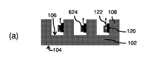
図1の左側には照明アセンブリ100の上面図が示される。図1の右側における、上面図の破線矢印によって画定される平面に沿った、照明アセンブリ100の一部の断面図。照明アセンブリ100は、直立壁108、108'を備える熱伝達要素102を備える。熱伝達要素102は第1の面104と、第1の面104とは反対側の第2の面106とを有する。図1の例では、第1の面104は、ヒートシンクが熱的に結合することができるヒートシンクインタフェースである。直立壁108、108'は、熱伝達要素102の第2の面106から離れるように延在している。直立側壁は第2の面106に隣接した壁表面107、107'を有し、これは壁表面107、107'が、その一辺において第2の面106と直接接触していることを意味し、また、壁表面107、107'と第2の面106との間には角度があることを意味し、この角度は、オプションとして85°~95°、オプションとして88°~92°、オプションとして実質的に90°に等しい。本明細書との関連で、「壁表面107、107'」という用語が使用される場合、第2の面106に隣接し、かつ細長い構造体が配置された壁表面のみを意味することに留意されたい(以下で説明されるように)。直立壁108、108'は熱伝導性材料で作製され、第1の面104に熱的に結合されている。図1の例では、熱伝達要素102の全体が熱伝導性材料で作製されており、従って、直立壁108、108'は第1の面104に熱的に結合されている。熱伝達要素102は均質な構造であってもよく、又は壁108、108'が作製され、熱伝達要素102のベースプレート(第1の面204と第2の面106を有するプレート)に熱的に別々に結合されてもよい。別の実施形態では、第1の面104にはまた、例えば、第1の面104がヒートシンクとなるような冷却フィンが設けられてもよいことに留意されたい。
A top view of the
照明アセンブリ100はまた、発光要素122、122'を備える細長い構造体120、120'を備える。細長い構造体120、120'は、例えば、5個以上の発光要素122、122'、又はオプションとして10個超の発光要素122、122'、又はオプションとして20個超の発光要素122、122を備える。細長い構造体120、120'はまた、発光要素122、122'に電力を供給するための電力接続部を含む。図1の例では、細長い構造体120、120'は、例えば、細長い可撓性基板(すなわち、図1に描かれるように、例えば要素120、120')を有する発光ダイオードストリップ(LEDストリップ)であり、細長い可撓性基板上にはLED(図1に描かれるように、これらは例えば発光要素122、122'である)に向かって電力を伝達する導電性トラックが設けられている。LEDは細長い構造体上に一種の列として提供され、このことは各LEDが最大で2つの直接隣接するLEDを有することを意味する。LEDが細長い構造体上に一種の列として提供されているという事実は、それらが電気的直列配置又は電気的並列配置で電気的に結合されていることを直接意味するわけではなく、両方の配置が可能であってもよく、また電気的直列配置又は電気的並列配置の組み合わせも可能である。
The
一般に、発光要素122、122'は固体発光体であってもよい。固体発光体の例は、発光ダイオード(LED)、有機発光ダイオードOLED、又は、例えばレーザダイオードである。発光要素122、122'はまた、固体発光体を備える固体発光体パッケージであってもよい。発光要素122、122'はまた、固体発光体を備えていてもよく、固体発光体は、固体発光体によって発せられた光を少なくとも部分的に別の色の光に変換するルミネッセント材料を含んでいてもよい。
In general, the
図1に示されるように、細長い構造体120、120'は、複数の直立壁108、108'の複数の壁表面107、107'上に配置される。発光要素122、122'が光を発しない、細長い構造体120、120'の表面は、壁表面107、107'と熱伝導的に接触するようにされている。細長構造体120、120'は、発光要素122、122'で発生した熱が直立壁108、108'に向かって伝導するように壁表面107、107'に配置されている。よって、発光要素122、122'によって発生された熱は、主として第1の面104に向かって伝達されるが、それは、その場所がヒートシンクとの結合又はヒートシンクの存在ゆえに温度がより低いからである。一般に、熱は比較的暖かい場所から比較的冷たい場所へ伝導するが、しかしながら、特定の発光要素122、122'で発生した熱は隣接する発光要素122、122'に伝導する場合がある。知られている解決策に比べて、これは隣接する発光要素122、122'に向かう熱伝達の顕著な低減である。よって、熱伝達要素は細長い構造体と組み合わされて、発光要素122、122'の過熱を防止する、良好な熱管理を提供する。平坦な基板上での発光要素のアレイ状の配置と比較して(背景技術の説明で議論したように)、直立壁108ゆえに及び発光要素の細長い配置ゆえに、発光要素間の全ての熱伝導経路の平均長さが増加された構成としても、図1の冷却構成を解釈することができることに留意されたい。よって、平均的に、各発光要素が隣接する発光要素から受ける熱は、より少なくなる。
As shown in FIG. 1, the
図1に示されるように、細長い構造体120、120'は螺旋状パターンに追従する。螺旋状パターンは、約3回の巻きを有する。図1は上面図であり、よって、螺旋状パターンは第2の面106と平行な平面内にあるように見える。螺旋状パターンは広く解釈されなければならないことに留意されたい。すなわち、螺旋の「ライン」は湾曲したラインを必ずしも意味せず、湾曲したラインは複数の直線で近似されてもよい。図1では、螺旋の中心周りの1回の「回転」は4本の直線で近似されている。螺旋の「回転」を、三角形状の螺旋になり得る、3本のラインで近似してもよいことに留意されたい。より多くの直線が使用されると、螺旋の湾曲した形状はより良く近似される。図1の例では、直立壁108、108'はまた、螺旋状パターンを形成することに留意されたい。直立壁は必ずしもこのパターンを形成しないことに留意されたい。それは後述されるように、細長い構造体120、120'に個別に結合された個々の直立壁を、細長い構造体120、120'が発光要素122、122'を有する位置にのみ設けてもよいからである。
As shown in FIG. 1, the
上述の実施例を踏まえ、細長い構造体120、120'が細長い可撓性基板に基づくLEDストリップの場合、隣接する壁表面107、107'の間の角で、可撓性基板を曲げることができるので、LEDストリップを壁表面107、107'に容易に設けることができる。
Based on the above embodiment, if the
細長い構造体120、120'の使用、及び直立壁108、108'の使用により、螺旋状パターンを得ることができる。図1で分かるように、比較的多数の発光要素122、122'が、細長い構造体120、120'が螺旋状パターンに曲げられた発光要素100内に集積化され得る。これにより、照明アセンブリ100のルーメン出力は比較的高く、一方で照明アセンブリ100は依然として小型である。発光要素が第2の表面上にアレイ状に設けられた照明アセンブリと比べて、ずっと多くの発光要素122、122'が図1の照明アセンブリ100内に設けられ得る。図1の実施形態を踏まえ、細長い構造体120、120'は、その上に発光要素122、122'が設けられた可撓性基板を有してもよい。
By using the
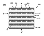
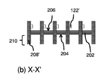
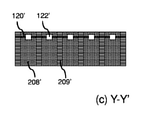
図2は照明アセンブリ200の別の実施形態を概略的に示す。照明アセンブリ200は照明アセンブリ100と類似し、類似した効果及び利点を有する。差異は以下で議論されることになる。図2の上部の(a)には上面図が示される。上面図には、2つの仮想線、すなわち、X及びX'で示される矢印の間の線と、Y及びY'で示される矢印の間の線とが示される。図2の左下の(b)では、線X-X'で規定される平面に沿った、照明アセンブリ200の断面図が示される。図2の右下の(c)では、線Y-Y'で規定される平面に沿った、照明アセンブリ200の断面図が示される。
FIG. 2 schematically shows another embodiment of the
図2の例では、この上面図で見た時に、細長い構造体120、120'は蛇行パターンで配置されている。図2(a)に示されるように、蛇行パターンは約4回の方向転換、すなわち照明アセンブリ200の左側で2回、照明アセンブリ200の右側で2回の方向転換を有する。これにより、図1の照明アセンブリを踏まえ、比較的多数の発光要素120を照明アセンブリ200に設けることができ、一方で照明アセンブリ200は比較的小型のままである。よって、照明アセンブリ200は相対的高いルーメン出力を有することができる。またこれに関連して、蛇行は幅広く解釈されなければならないことに留意すべきであり、すなわち細長い構造体120、120'は、川が蛇行するように、きれいな曲線で蛇行することは必須ではなく、直線で形成されるパターンで蛇行してもよい。換言すれば、蛇行した川のきれいな曲線を比較的少数の直線で近似してもよい。
In the example of FIG. 2, when viewed from this top view, the
図2の例では、熱伝達要素のベースは熱絶縁性プレート202である。この熱絶縁性プレート202は第1の面204を有し、第1の面において、ヒートシンク210を形成する冷却フィンが延在している。熱絶縁性プレート202の第2の面206(第1の面204の反対側の面である)には、複数の直立壁208、208'があり、直立壁は熱絶縁性プレート202を通って延在し、第1の面204において熱絶縁性プレート202から突出して冷却フィンを形成する。これにより、複数の直立壁208は、熱絶縁性プレート202の第1の面204に熱的に結合されている。複数の直立壁208の間には、直立した熱絶縁性構造209が設けられて、ある直立側壁208から隣接する直立側壁208に向かう熱伝達を防止する。これにより、発光要素122、122'が互いに加熱し合うことが防止される。各発光要素122、122'は、それ自身の冷却要素/冷却フィンを有する。これにより、各発光要素122、122'の効果的な冷却が得られ、一方で隣接する発光要素122、122'の熱を受けることによる過熱が大幅に防止される。
In the example of FIG. 2, the base of the heat transfer element is the
(c)にてY-Y'に沿った断面図に示されるように、直立した熱絶縁性構造209はまた、第1の面204に至るまで延在してもよく、個々の冷却フィンの間に存在してもよい。しかし、これは必須ではなく、熱絶縁性構造209はまた、第1の面104に存在しなくてもよい。各発光要素122、122'が、それ自身の冷却フィンを有することを実現するためには、熱絶縁性構造209が熱絶縁性プレート202の第2の面206に存在することも必須ではない。熱絶縁性構造209は、付加的な機械的安定性を提供するために、そこにあってもよい。
As shown in the cross-sectional view along YY'in (c), the upright
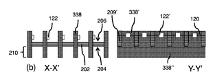
図3は図1又は図2の照明アセンブリのうちの1つの代替実施形態の、いくつかの断面図を概略的に示す。図2との関連で述べたように、各発光要素には個々の冷却フィンが設けられていてもよい。最上部の(a)に示され、(a)の右側のY-Y'断面図で分かるように、2つの発光要素122、122'は両方とも、第2の面206に、熱絶縁性構造209、209によって分離された個々の直立壁308、308'を有していてもよく、一方で第1の面204において、これら2つの直立壁308、308'は1つの冷却フィン308''に熱的に結合していてもよい。これにより、2つの発光要素122、122'のみが互いに熱を伝達することができる。
FIG. 3 schematically shows some cross-sectional views of one alternative embodiment of the lighting assembly of FIG. 1 or FIG. As mentioned in the context of FIG. 2, each light emitting element may be provided with individual cooling fins. As shown in the uppermost portion (a) and shown in the YY'cross section on the right side of (a), the two
(b)に示され、(b)のY-Y'断面図で分かるように、熱絶縁性プレート202の第1の面204において、直立壁338、338'が1つの冷却フィン338''に結合されてもよく、これにより、直立壁338、338'のグループが、熱伝導経路を介し冷却フィン338''を介して互いに熱を供給してもよい。とりわけ、(b)のこの例では、及び例えば図2の照明アセンブリとの関連では、発光要素122、122'の各列は互いに熱的に結合されているが、個々の列は互いに熱的に絶縁されており、それにより列が隣接列での発熱により熱くなり過ぎることが防止される。
As shown in (b) and as can be seen in the YY'cross section of (b), in the
(c)に示されるように、熱伝達要素のベースは熱伝導性プレート362であってもよく、そこから熱伝導性の直立壁368、368'が第2の面において延在し、発光要素122、122'の各々又はグループは、単一で延在する熱伝導性の直立壁368、368'と結合されている。熱絶縁性要素369'は、熱伝導性の直立壁368、368'の間に設けられてもよい。(c)の例では、熱伝導性プレート362は第1の面204に冷却フィン368''を有する。
As shown in (c), the base of the heat transfer element may be the heat
図4は照明アセンブリ400の更なる実施形態を概略的に示す。照明アセンブリ400は、前述の照明アセンブリの実施形態と類似し、類似した効果及び利点を有する。差異は以下で議論されている。図4は上面図を示す。照明アセンブリは、上面図で見た時、円形形状を有する。熱伝達要素の第2の面406に、熱伝導性材料の個々の直立壁408が設けられる。直立壁408は、熱伝達要素の第1の面(第2の面406の反対側にあり、図示されていない)に熱的に結合されている。前述した実施形態を踏まえ、直立壁408は第1の面から外に延在して冷却フィンを形成してもよく、あるいはヒートシンクインタフェースへの、又はヒートシンクへの良好な熱経路が得られるように、第1の面に達するまで延在してもよい。個々の直立壁408は、周囲空気によって互いに分離されている。熱伝達要素のベースプレート(その第2の面406が示されている)は、熱伝導性材料又は熱絶縁性材料で作製されていてもよい。個々の直立壁408は、ベースプレートの中央の周りに配置され、第2の面406に直角な平面内で見て、およそ螺旋形状を形成する。照明アセンブリ400はまた、一連の発光体要素122の間に配置された電力線420を備える細長い要素を備える。電力線420は僅かに可撓性であり、細長い要素を、少なくとも2回の巻きを有する螺旋の形状(第2の面406に平行な平面に沿った断面図で見た時に)に配置することを可能にする。細長い要素が発光要素122を有する位置では、発光要素122の裏面は直立壁408のうちの1つに熱的に結合されている。発光要素122の裏面は、光が発せられる最大表面とは反対側の面である。図2の議論を踏まえ、個々の発光要素122は、照明アセンブリ400によって良好に冷却され、異なる発光要素122間には相互加熱はほとんど生じない。
FIG. 4 schematically shows a further embodiment of the
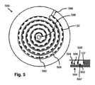
図5は照明アセンブリ500の更なる別の実施形態を概略的に示す。照明アセンブリ500は、前述の照明アセンブリの実施形態と類似し、類似した効果及び利点を有する。差異は以下で議論される。左端に上面図が示され、図5の右下には、照明アセンブリ500の一部の断面図が示されている。照明アセンブリ500は熱伝導性プレート502によって形成され、その中に、5回の巻きを有する螺旋状パターンに従ってチャネル592、592'が形成されている。チャネル592、592'の隣接する部分の間には、直立壁508、508'が残存する。照明アセンブリ500は、熱伝導性プレート502をベースとしているので、直立壁508、508'は、熱伝導性プレート502の第1の面504に向かって熱的に結合されている。本明細書との関係においては、チャネル592、592'の底部は直立壁508、508'が延在する第2の面である。図5では、細長い構造体の発光要素122、122'のみが描かれている。先の実施形態を踏まえ、LEDストリップ、又は電力線によって互いに接続された固体発光体を有する細長い構造体、又は任意の他の適切な細長い構造体が使用され得る。
FIG. 5 schematically illustrates yet another embodiment of the
オプションとして、チャネルの上部には、これを通して光を周囲に発することができる光透過性プレート594が設けられている。これにより、チャネル592、592'は一種のチャネルを形成し、これを通して発光要素122、122'を冷却するための空気又は任意の流体などの冷却材が搬送されてもよい。この目的で、照明アセンブリ500は冷却材入口596及び冷却材出口598を含んでいてもよい。入口596及び出口598が描かれている位置は、1つは螺旋の最後にあり、もう1つは螺旋の最初にあるので、比較的良い位置である。しかし、入口596及び出口598の位置の実施形態は提示された位置に限定されず、冷却材がチャネルの一部を又はチャネルを通って流れることができるのか、及び発光要素122、122'の少なくとも一部が冷却材で冷却されるのか、に関係している。
Optionally, the top of the channel is provided with a
図6は、照明アセンブリからの光出力を向上するために光学要素が導入された、前述した照明アセンブリの断面図を概略的に示す。全ての断面図において、熱伝達要素102のベースプレートの第2の面106から延在する直立壁108を見ることができる。先の実施形態を踏まえ、ベースプレートは熱伝導性材料又は熱絶縁性材料で作製されていてもよい。先の実施形態を踏まえ、直立壁108は、ベースプレートを貫通して第1の面104に向かって延在していてもよく、オプションとして冷却フィンを第1の面104に形成していてもよい。
FIG. 6 schematically shows a cross-sectional view of the aforementioned lighting assembly into which optical elements have been introduced to improve the light output from the lighting assembly. In all cross-sectional views, an
図6(b)で分かるように、及び先に提示された断面図でも明らかなように、発光要素122は、直立壁108の間に形成されたチャネルの中に光を発するであろう可能性が最も高い。付加的な光学要素、光アウトカップリング要素、又は反射材料が、光がチャネルの表面上に入射するチャネル内の位置に設けられてもよい。例えば、(b)では、(白色)反射材料612が発光要素122の対面に設けられていることが示されている。(白色)反射材料は拡散反射性であってもよい。比較的均質な光出力が得られるように、チャネルの表面の全体にも、この(白色)反射材料612が設けられてもよいことに留意されたい。
As can be seen in FIG. 6 (b) and as evidenced by the cross section presented above, the
(b)に提示された解決策とは対照的に、(a)に示されるように、照明アセンブリの光出力窓の方に面する、発光要素122の表面から光が直接伝達されるように、発光要素122上部に、特定の光反射層624が設けてもよい。その時、チャネルの中に発せられる光の量は制限される。別の実施形態では、光の大部分を、少なくとも側面のうちの1つを通して発する発光要素である、側面放射発光要素が用いられる。側面放射発光要素は、これらの側面が周囲に面するように、すなわち照明アセンブリの光出射窓の方に面するように、照明アセンブリ内で配置されなければならない。
In contrast to the solution presented in (b), as shown in (a), light is transmitted directly from the surface of the
(b)の解決策の代替として、(c)に示されるように、透明な楔形の要素などの、光学式の光ガイド要素614をチャネルの中に設け、それにより光が透明な楔形の要素により照明アセンブリの光出力窓(これは図6に関してはチャネルの入口である)に向かって導かれるようにしてもよい。
As an alternative to the solution of (b), an optical
(b)の解決策の代替として、(d)に示すように、チャネルの表面に光拡散要素が設けられてもよい。光拡散要素上に入射する光は、多数の方向に、従って一部は照明アセンブリの光出力窓にも向かって回折される。これは、チャネルの中に、更に回折された光が照明アセンブリの光出力窓に向かって依然として反射されるように、チャネルの表面が反射性でもある場合には、とりわけ有益である。 As an alternative to the solution of (b), a light diffusing element may be provided on the surface of the channel as shown in (d). The light incident on the light diffusing element is diffracted in many directions, and thus in part towards the light output window of the lighting assembly. This is especially useful if the surface of the channel is also reflective so that further diffracted light is still reflected into the channel towards the light output window of the lighting assembly.
(b)の解決策の代替として、又は更に(b)の解決策と組み合わせて、発光要素122の向かい側のチャネル表面はまた、発光要素122から受光した光を別の色の光に部分的に変換するルミネッセント材料を含むルミネッセント要素618が設けられてもよい。多くの場合、ルミネッセント材料は入射する光及び別の色の光を拡散させ、それにより、組み合わされた光の少なくとも有意な部分が、照明アセンブリの光出力窓に向かって伝達される。
As an alternative to the solution of (b), or in combination with the solution of (b), the channel surface opposite the
図7は前述した照明アセンブリの代替実施形態のいくつかの断面図を概略的に示す。(a)に示される実施形態は、チャネル内で、少なくとも発光要素122が発する光が入射する位置に、鋭角の角の代わりに面取りされた角を有し、それにより面取りされた角703が、光を照明アセンブリの光出力窓に向かって光を反射するミラー(又は拡散反射性のミラー)として機能してもよい。チャネルの表面が少なくとも一部の光を反射することが前提である。全ての議論された実施形態では、チャネルの表面は鏡面反射性又は拡散反射性であってもよい。全ての議論された実施形態では、チャネルの表面は、表面に入射する光の少なくとも50%、又はオプションとして表面に入射する光の少なくとも75%、又はオプションとして、表面に入射する光の少なくとも90%を反射してもよい。
FIG. 7 schematically shows some cross-sectional views of the alternative embodiments of the lighting assembly described above. The embodiment shown in (a) has a chamfered angle instead of a sharp angle at least at a position in the channel where the light emitted by the
(a)の解決策の代替として、(b)に示されるように、発光要素122の向かい側のチャネルの角はまた、付加的な光反射材料705又は付加的なルミネッセント材料によって、充填/面取りされ得る(図6(e)の議論を踏まえて)。
As an alternative to the solution of (a), as shown in (b), the corners of the channel opposite the
(c)では、第1の面104に、ヒートシンク210を形成する冷却フィンが設けられていてもよいことが示される。先の実施形態では、ヒートシンクは、熱伝達要素102を完全に貫通して、更に第1の面から延在する直立壁によって形成される。(c)の例では、直立壁は熱伝達要素102を完全に貫通して延在してはおらず、別個の壁/フィンが第1の面104に設けられている。
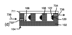
In (c), it is shown that the
(d)では、チャネルが光透過性パネル711を用いて閉じられてもよいことが示される。また、一例として、冷却材736をチャネルに供給し、チャネルから受け取るための、冷却材入口732及び冷却材出口734が設けられてもよい。
In (d), it is shown that the channel may be closed using the
図8は、細長い構造体及び/又は直立壁が追従することができる、蛇行パターン又は螺旋状パターンの実施形態を概略的に示す。 FIG. 8 schematically illustrates an embodiment of a meandering or spiral pattern that an elongated structure and / or an upright wall can follow.
図9は、細長い構造体の実施形態を概略的に示す。(a)では、LEDストリップ900が、そのような細長い構造体の一例として示されている。LEDストリップは可撓性基板をベースとしており、その上には、導電性トラックが設けられ、これに発光ダイオード(LED)が設けられている。(b)では、図4との関連で議論された細長い構造体910が示される。細長い構造体910は、発光要素122(例えば、固体発光体)を備え、発光要素122の間の電力線420を備える。電力線420は、細長い構造体を螺旋状形状又は蛇行形状に曲げるのに十分な可撓性を有していてもよい。(c)では、少なくとも螺旋状形状又は蛇行形状を形成するのに十分な可撓性を有する基板930をベースとする、ストリップ状の要素940が描かれている。基板930上には、発光要素に電力を供給する、電力線又は導電性トラック920が設けられている。(a)、(b)、及び(c)で分かるように、発光要素は順次並べて配置されている。順次並んでいるということは、しかしながら、発光要素が、厳密な直列配置又は並列配置に構成されていることを意味しない。(b)及び(c)の例では、発光要素122の間には2つだけの電気接続部が描かれているが、実施形態はこの数に限定されず、発光要素122はまた、電気的直列配置又は電気的並列配置の任意の組み合わせで構成され得るように、3つ以上の電気接続部が設けられてもよいことにもまた留意されたい。
FIG. 9 schematically shows an embodiment of an elongated structure. In (a), the
図10は、ランプ1000及び照明器具1050の実施形態を概略的に示す。ランプ1000及び照明器具1050によって高ルーメン出力が供給され得るように、ランプ1000及び照明器具1050の両方が、上述の照明アセンブリの実施形態のうちの1つを備えていてもよい。照明アセンブリは小型であり、よってランプ1000及び照明器具1050内で使用することができる。
FIG. 10 schematically shows an embodiment of a
要約すると、照明アセンブリ、光源、ランプ、及び照明器具が提供される。照明アセンブリは、熱伝達要素と、発光要素及び電力接続部を含む細長い構造体とを備える。熱伝達要素は、第1の面にヒートシンクインタフェース又はヒートシンク要素を備える。反対側の第2の面には、第2の面から離れるように延在する1つ以上の直立壁が設けられている。直立壁は熱伝導性であり、第1の面に熱的に結合されている。細長い構造体は、直立壁のうちの少なくとも1つの壁表面上に配置される。壁表面は第2の面に隣接している。細長い構造体の、光が発せられない表面は、壁表面に熱的に結合されている。細長い構造体によって形成されるパターンは、蛇行パターン又は螺旋状パターンである。 In summary, lighting assemblies, light sources, lamps, and luminaires are provided. The lighting assembly comprises a heat transfer element and an elongated structure including a light emitting element and a power connection. The heat transfer element comprises a heatsink interface or heatsink element on the first surface. The second surface on the opposite side is provided with one or more upright walls extending away from the second surface. The upright wall is thermally conductive and is thermally coupled to the first surface. The elongated structure is placed on the surface of at least one of the upright walls. The wall surface is adjacent to the second surface. The non-lighting surface of the elongated structure is thermally coupled to the wall surface. The pattern formed by the elongated structure is a meandering pattern or a spiral pattern.
更なる実施形態が以降の節に記載される。
1.光を発するための照明アセンブリ(100、200、400、500)であって、照明アセンブリ(100、200、400、500)は、
発光要素(122、122')と、発光要素(122、122')に電力を供給するための電力接続部(420、920)とを含む、細長い構造体(120、900、910、940)であって、発光要素(122、122')は細長い構造体(120、900、910、940)の長手方向に配置されている、細長い構造体と、
第1の面(104、204、504)にヒートシンクインタフェース又はヒートシンク要素(210)を備え、第2の面(106、206、406、506)に、第2の面(106、206、406、506)から離れるように延在する1つ以上の直立壁(108、208、338、368、408、508)を備える、熱伝達要素(102)であって、第2の面(106、206、406、506)は第1の面(104、204、504)の反対側であり、1つ以上の直立壁(108、208、338、368、408、508)は熱伝導性材料を含み第1の面(104、204、504)に熱的に結合されている、熱伝達要素と、を備え、
細長い構造体(120、900、910、940)は、1つ以上の直立壁のうちの少なくとも1つの壁表面(107、107')上に配置され、壁表面(107、107')は、第2の面(106、206、406、506)に隣接する、1つ以上の直立壁(108、208、338、368、408、508)の表面のうちの1つであり、発光要素(122、122')によって光が発せられない、細長い構造体(120、900、910、940)の表面は、壁表面(107、107')に熱的に結合しており、細長い構造体(120、900、910、940)によって形成されるパターンは、蛇行パターン又は螺旋状パターンであり、パターンは第2の面(106、206、406、506)に平行な横断面内に画定されている、照明アセンブリ。
2.1つ以上の直立壁(108、208、338、368、408、508)の少なくとも一部の間のスペースがチャネル(592、592')を形成し、発光要素(122、122')は発光要素の光の少なくとも一部をチャネル(592、592')の中に発するように配置されている、節1に記載の照明アセンブリ(100、200、400、500)。
3.発光要素(122、122')によって照射される1つ以上のチャネル(592、592')の位置の少なくとも一部において、チャネル内に、反射材料(612、705)が設けられるか、又は光アウトカップリング要素(614、616、118)が設けられる、節2に記載の照明アセンブリ。
4.発光要素(122、122')は、第2の面(106、206、406、506)に平行な方向に光を発するように配置された、節1乃至3の何れか一節に記載の照明アセンブリ(100、200、400、500)。
5.1つ以上の直立壁(108、208、338、368、408、508)の少なくとも一部の間のスペースが1つ以上のチャネル(592、592')を形成し、チャネルは第2の面の向かい側において光透過性材料(594、711)で覆われて、1つ以上のチャネル(592、592')の反対側が封止され、1つ以上のチャネル(592、592')には冷却材入口(596、732)及び冷却材出口(598、734)が設けられており、細長い構造体(120、900、910、940)の発光要素(122、122')を冷却するために冷却材(736)が1つ以上のチャネルを通って流れることを可能にしている、節1乃至4の何れか一節に記載の照明アセンブリ(100、200、400、500)。
6.1つ以上の直立壁(108、208、338、368、408、508)の一部によって形成される壁パターンは蛇行パターン又は螺旋状パターンであり、壁パターンは第2の面(106、206、406、506)に平行な横断面内に画定されている、節1乃至5の何れか一節に記載の照明アセンブリ(100、200、400、500)。
7.1つ以上の直立壁(108、208、338、368、408、508)の第1の部分は1つ以上の直立壁(108、208、338、368、408、508)の第2の部分から熱的に絶縁され、一方、第1の部分の1つ以上の直立壁(108、208、338、368、408、508)と、第2の部分の1つ以上の直立壁は、第1の面(104、204、504)に熱的に結合されている、節1乃至6の何れか一節に記載の照明アセンブリ(100、200、400、500)。
8.熱伝達要素(102)は、第1の面(104、204、504)に冷却フィン(210)を備える、節1乃至7の何れか一節に記載の照明アセンブリ(100、200、400、500)。
9.細長い構造体(120、900、910、940)は、可撓性基板で作られたLEDストリップ(900)であり、可撓性基板上には固体発光体が設けられ、かつ電力接続部を形成する導電性トラックが設けられている、節1乃至8の何れか一節に記載の照明アセンブリ(100、200、400、500)。
10.細長い構造体(120、900、910、940)は、電力接続部を形成するワイヤ(420、920)を用いて互いに結合された一連の固体発光体によって形成される、節1乃至8の何れか一節に記載の照明アセンブリ(100、200、400、500)。
11.発光要素(122、122')は固体発光体である、節1乃至10の何れか一節に記載の照明アセンブリ(100、200、400、500)。
12.壁表面(107、107')と第2の面(106、206、406、506)との間の角度は、85°~95°であり、オプションとして88°~92°であり、オプションとして実質的に90°に等しい、節1乃至11の何れか一節に記載の照明アセンブリ(100、200、400、500)。
13.節1乃至12の何れか一節に記載の、照明アセンブリ(100、200、400、500)を備える、光源。
14.節1乃至12の何れか一節に記載の照明アセンブリ(100、200、400、500)を備える、又は節13に記載の光源を備える、ランプ(1000)。
15.節1乃至12の何れか一節に記載の照明アセンブリ(100、200、400、500)を備える、又は節13に記載の光源を備える、又は節14に記載のランプ(1000)を備える、照明器具(1050)。
Further embodiments are described in the following sections.
1. 1. A lighting assembly (100, 200, 400, 500) for emitting light, wherein the lighting assembly (100, 200, 400, 500) is.
In an elongated structure (120, 900, 910, 940) comprising a light emitting element (122, 122') and a power connection (420, 920) for supplying power to the light emitting element (122, 122'). The light emitting element (122, 122') is an elongated structure arranged in the longitudinal direction of the elongated structure (120, 900, 910, 940).
The first surface (104, 204, 504) comprises a heat sink interface or heat sink element (210) and the second surface (106, 206, 406, 506) has a second surface (106, 206, 406, 506). A second surface (106, 206, 406) of a heat transfer element (102) comprising one or more upright walls (108, 208, 338, 368, 408, 508) extending away from). , 506) are opposite sides of the first surface (104, 204, 504) and one or more upright walls (108, 208, 338, 368, 408, 508) contain a heat transfer material and a first. With a heat transfer element, which is thermally coupled to the surface (104, 204, 504),
Elongated structures (120, 900, 910, 940) are placed on at least one wall surface (107, 107') of one or more upright walls, with the wall surface (107, 107') being the first. One of the surfaces of one or more upright walls (108, 208, 338, 368, 408, 508) adjacent to two faces (106, 206, 406, 506) and a light emitting element (122, The surface of the elongated structure (120, 900, 910, 940), which is not emitted by 122'), is thermally bonded to the wall surface (107, 107') and is elongated structure (120, 900'). , 910, 940) is a meandering pattern or a spiral pattern, the pattern is defined in a cross section parallel to the second plane (106, 206, 406, 506), a lighting assembly. ..
2. The space between at least some of the upright walls (108, 208, 338, 368, 408, 508) forms the channel (592, 592') and the light emitting element (122, 122'). The lighting assembly (100, 200, 400, 500) according to section 1, wherein at least a portion of the light of the light emitting element is arranged to emit into the channel (592, 592').
3. 3. Reflective material (612, 705) is provided within the channel or light out at least in part of the position of one or more channels (592, 592') illuminated by the light emitting element (122, 122'). The lighting assembly according to section 2, wherein the coupling elements (614, 616, 118) are provided.
4. The lighting assembly according to any one of sections 1 to 3, wherein the light emitting element (122, 122') is arranged to emit light in a direction parallel to the second surface (106, 206, 406, 506). (100, 200, 400, 500).
5. The space between at least some of the one or more upright walls (108, 208, 338, 368, 408, 508) forms one or more channels (592, 592'), and the channels are second. On the opposite side of the face, covered with a light transmissive material (594, 711), the opposite side of one or more channels (592, 592') is sealed and one or more channels (592, 592') are cooled. A material inlet (596, 732) and a coolant outlet (598, 734) are provided to cool the coolant element (122, 122') of the elongated structure (120, 900, 910, 940). The lighting assembly (100, 200, 400, 500) according to any one of sections 1 to 4, which allows (736) to flow through one or more channels.
6. The wall pattern formed by a portion of one or more upright walls (108, 208, 338, 368, 408, 508) is a meandering or spiral pattern and the wall pattern is a second surface (106, 106,). The lighting assembly (100, 200, 400, 500) according to any one of sections 1 to 5, defined in a cross section parallel to 206, 406, 506).
7. The first part of one or more upright walls (108, 208, 338, 368, 408, 508) is the second part of one or more upright walls (108, 208, 338, 368, 408, 508). One or more upright walls (108, 208, 338, 368, 408, 508) of the first part and one or more upright walls of the second part are thermally insulated from the part, while the first part has one or more upright walls. The lighting assembly (100, 200, 400, 500) according to any one of sections 1 to 6, which is thermally coupled to surface 1 (104, 204, 504).
8. The lighting assembly (100, 200, 400, 500) according to any one of sections 1 to 7, wherein the heat transfer element (102) comprises cooling fins (210) on the first surface (104, 204, 504). ..
9. The elongated structure (120, 900, 910, 940) is an LED strip (900) made of a flexible substrate, on which a solid light emitter is provided and a power connection is formed. The lighting assembly (100, 200, 400, 500) according to any one of sections 1 to 8, wherein the conductive track is provided.
10. The elongated structure (120, 900, 910, 940) is any of nodes 1-8 formed by a series of solid illuminants coupled to each other using wires (420, 920) forming a power connection. Lighting assembly (100, 200, 400, 500) according to a section.
11. The lighting assembly (100, 200, 400, 500) according to any one of sections 1 to 10, wherein the light emitting element (122, 122') is a solid light emitter.
12. The angle between the wall surface (107, 107') and the second surface (106, 206, 406, 506) is 85 ° to 95 °, optionally 88 ° to 92 °, and optionally substantial. The lighting assembly (100, 200, 400, 500) according to any one of sections 1 to 11, which is equal to 90 °.
13. A light source comprising the lighting assembly (100, 200, 400, 500) according to any one of sections 1-12.
14. A lamp (1000) comprising the lighting assembly (100, 200, 400, 500) according to any one of sections 1-12, or the light source according to section 13.
15. Lighting fixtures comprising the lighting assembly (100, 200, 400, 500) according to any one of sections 1-12, or the light source according to section 13, or the lamp (1000) according to section 14. (1050).
明確化のための上記記載は、様々な機能的ユニットを参照して、本発明の実施形態を記載してきたことが理解されよう。しかし、様々な機能的ユニット間での機能性の任意の好適な配分が、本発明から逸脱せずに、使用され得ることが明らかとなるであろう。例えば、別個のユニットによって実施されるように示された機能性は、1つのユニットによって実施されてもよく、又は複数のユニットによって提供されてもよい。それゆえ、特定の機能的ユニットへの参照は、厳密に論理的又は物理的な構造又は構成を示すというよりは、むしろ記載された機能性を提供するための好適な手段への参照としてのみ見なされるべきである。本発明は、ハードウェア、ソフトウェア、ファームウェア、又はこれらの任意の組み合わせを含む任意の好適な形態で実施することができる。 It will be appreciated that the above description for clarification has described embodiments of the invention with reference to various functional units. However, it will become clear that any suitable distribution of functionality among the various functional units can be used without departing from the present invention. For example, the functionality shown to be performed by separate units may be performed by one unit or may be provided by multiple units. Therefore, a reference to a particular functional unit is considered only as a reference to a suitable means for providing the described functionality, rather than exhibiting a strictly logical or physical structure or configuration. Should be. The present invention can be implemented in any suitable form, including hardware, software, firmware, or any combination thereof.
本明細書では、用語「備える(comprising)」は、列挙されたもの以外の他の要素又はステップの存在を除外せず、また、要素に先立つ用語「a」又は「an」は、複数のそのような要素の存在を除外せず、いかなる参照符号も特許請求の範囲を限定しないことに留意されたい。更に、本発明は、それらの実施形態には限定されず、本発明は、上述の、又は互いに異なる従属請求項に列挙された、あらゆる新規な特徴、又は特徴の組み合わせにある。 As used herein, the term "comprising" does not exclude the presence of other elements or steps other than those listed, and the term "a" or "an" preceding an element is a plurality of such elements. Note that it does not rule out the existence of such elements and that no reference code limits the scope of the claims. Furthermore, the invention is not limited to those embodiments, but the invention is in any novel feature, or combination of features listed above or in different dependent claims.
Claims (14)
可撓性基板を含み、発光要素と、前記可撓性基板上の前記発光要素に電力を供給するための電力接続部とを含む、細長い構造体であって、前記発光要素は前記細長い構造体の長手方向に配置されている、細長い構造体と、
第1の面と反対側の第2の面とを備えるベースプレートを備える熱伝達要素であって、前記熱伝達要素は、前記第1の面にヒートシンクインタフェース又はヒートシンク要素を備え、前記第2の面に、前記第2の面から離れるように延在する1つ以上の直立壁を備え、前記第2の面は前記第1の面の反対側であり、前記1つ以上の直立壁は熱伝導性材料を含み前記第1の面に熱的に結合されている、熱伝達要素と、を備え、
前記細長い構造体は、前記1つ以上の直立壁のうちの少なくとも1つの壁表面上に配置され、前記壁表面は、前記第2の面に隣接する、前記1つ以上の直立壁の表面のうちの1つであり、前記発光要素によって光が発せられない、前記細長い構造体の表面は、前記壁表面に熱的に結合しており、前記細長い構造体によって形成されるパターンは、蛇行パターン又は螺旋状パターンであり、前記パターンは前記第2の面に平行な横断面内に画定されており、前記蛇行パターンは少なくとも3回の方向転換を含み、前記螺旋状パターンは複数回の巻きを含み、
前記1つ以上の直立壁の少なくとも一部の間のスペースがチャネルを形成し、前記発光要素は前記発光要素の光の少なくとも一部を前記チャネルの中に発するように配置されている、照明アセンブリ。 A lighting assembly for emitting light, said lighting assembly
An elongated structure comprising a flexible substrate, comprising a light emitting element and a power connection for supplying power to the light emitting element on the flexible substrate, wherein the light emitting element is the elongated structure. With an elongated structure arranged in the longitudinal direction of
A heat transfer element comprising a base plate comprising a first surface and a second surface opposite the first surface, wherein the heat transfer element comprises a heat sink interface or heat sink element on the first surface and the second surface. The second surface is provided with one or more upright walls extending away from the second surface, the second surface is opposite to the first surface, and the one or more upright walls are heat transferable. It comprises a heat transfer element, which comprises a sex material and is thermally coupled to the first surface.
The elongated structure is placed on the surface of at least one of the one or more upright walls, the wall surface being the surface of the one or more upright walls adjacent to the second surface. The surface of the elongated structure, which is one of them and is not emitted by the light emitting element, is thermally bonded to the wall surface, and the pattern formed by the elongated structure is a meandering pattern. Alternatively, it is a spiral pattern, wherein the pattern is defined in a cross section parallel to the second plane, the meandering pattern contains at least three diversions, and the spiral pattern has multiple turns. Including,
A lighting assembly in which the space between at least a portion of the one or more upright walls forms a channel and the light emitting element is arranged to emit at least a portion of the light of the light emitting element into the channel. ..
Applications Claiming Priority (3)
| Application Number | Priority Date | Filing Date | Title |
|---|---|---|---|
| EP16176566 | 2016-06-28 | ||
| EP16176566.4 | 2016-06-28 | ||
| PCT/EP2017/064984 WO2018001781A1 (en) | 2016-06-28 | 2017-06-20 | Lighting assembly for emitting high intensity light, a light source, a lamp and a luminaire |
Publications (3)
| Publication Number | Publication Date |
|---|---|
| JP2019525391A JP2019525391A (en) | 2019-09-05 |
| JP2019525391A5 JP2019525391A5 (en) | 2020-08-06 |
| JP7002480B2 true JP7002480B2 (en) | 2022-02-04 |
Family
ID=56296549
Family Applications (1)
| Application Number | Title | Priority Date | Filing Date |
|---|---|---|---|
| JP2018567571A Active JP7002480B2 (en) | 2016-06-28 | 2017-06-20 | Lighting assemblies, light sources, lamps and plumbing fixtures that emit high-intensity light |
Country Status (5)
| Country | Link |
|---|---|
| US (1) | US10627099B2 (en) |
| EP (1) | EP3475608B1 (en) |
| JP (1) | JP7002480B2 (en) |
| CN (1) | CN109416170B (en) |
| WO (1) | WO2018001781A1 (en) |
Families Citing this family (6)
| Publication number | Priority date | Publication date | Assignee | Title |
|---|---|---|---|---|
| WO2020089146A1 (en) * | 2018-10-29 | 2020-05-07 | Signify Holding B.V. | Light-emitting device with solid-state light sources |
| CN113853499B (en) * | 2019-05-20 | 2024-03-29 | 昕诺飞控股有限公司 | Light source comprising a substrate and a heat sink structure |
| US20200386392A1 (en) * | 2019-06-10 | 2020-12-10 | Applied Materials, Inc. | Heat exchange arrangement for light emitting diode lamp modules |
| US20220403987A1 (en) * | 2019-11-21 | 2022-12-22 | Signify Holding B.V. | A lighting emitting device |
| KR20220026684A (en) * | 2020-08-26 | 2022-03-07 | 엘지이노텍 주식회사 | Lighting apparatus and lamp including the same |
| EP4229327A1 (en) | 2020-10-15 | 2023-08-23 | Signify Holding B.V. | A lighting device and a method of manufacturing a lighting device |
Citations (6)
| Publication number | Priority date | Publication date | Assignee | Title |
|---|---|---|---|---|
| JP2009176443A (en) | 2008-01-22 | 2009-08-06 | Ushio Inc | Light source device |
| JP2010097736A (en) | 2008-10-14 | 2010-04-30 | Citizen Electronics Co Ltd | Plane light source and liquid crystal display |
| JP2013033938A (en) | 2011-06-28 | 2013-02-14 | Koito Mfg Co Ltd | Light-emitting module |
| JP2014150072A (en) | 2011-02-01 | 2014-08-21 | Switch Bulb Co Inc | Led bulb |
| JP2014175265A (en) | 2013-03-12 | 2014-09-22 | Sharp Corp | Light-emitting device |
| JP2016507883A (en) | 2013-02-25 | 2016-03-10 | コーニンクレッカ フィリップス エヌ ヴェKoninklijke Philips N.V. | Lighting device including roll |
Family Cites Families (17)
| Publication number | Priority date | Publication date | Assignee | Title |
|---|---|---|---|---|
| US6578986B2 (en) | 2001-06-29 | 2003-06-17 | Permlight Products, Inc. | Modular mounting arrangement and method for light emitting diodes |
| AU2003228617A1 (en) * | 2002-04-18 | 2003-11-03 | Walker Digital, Llc | Method and apparatus for providing a bonus to a player based on a credit balance |
| US7205719B2 (en) * | 2004-12-27 | 2007-04-17 | Industrial Technology Research Institute | Light source with LED and optical protrusions |
| JP2006258888A (en) | 2005-03-15 | 2006-09-28 | Prosper:Kk | Circuit board body and display device using the same |
| CA2605209C (en) * | 2005-04-19 | 2013-10-22 | Denki Kagaku Kogyo Kabushiki Kaisha | Metal base circuit board, light-emitting diode and led light source unit |
| DE102006033894B4 (en) * | 2005-12-16 | 2019-05-09 | Osram Gmbh | Lighting device and display device with a lighting device |
| US20080253116A1 (en) | 2007-04-16 | 2008-10-16 | Yung-Chiang Liao | Lamp Structure |
| DE102007043904A1 (en) * | 2007-09-14 | 2009-03-19 | Osram Gesellschaft mit beschränkter Haftung | Luminous device |
| CN102782391B (en) * | 2010-02-12 | 2016-08-03 | 科锐公司 | Solid state illumination device and assembly method thereof |
| US9395057B2 (en) | 2011-02-07 | 2016-07-19 | Cree, Inc. | Lighting device with flexibly coupled heatsinks |
| JP6062148B2 (en) * | 2011-12-26 | 2017-01-18 | 株式会社小糸製作所 | Vehicle lighting |
| TW201341714A (en) * | 2012-04-12 | 2013-10-16 | Lextar Electronics Corp | Light emitting device |
| DE102012109131A1 (en) | 2012-09-27 | 2014-03-27 | Osram Opto Semiconductors Gmbh | An optoelectronic component device, method for producing an optoelectronic component device and method for operating an optoelectronic component device |
| US9528689B2 (en) * | 2013-03-13 | 2016-12-27 | Palo Alto Research Center Incorporated | LED lighting device with cured structural support |
| KR102040184B1 (en) * | 2013-05-31 | 2019-11-04 | 엘지이노텍 주식회사 | Circuit board, lighting device having the circuit board and board housing |
| KR20150084311A (en) * | 2014-01-13 | 2015-07-22 | 삼성전자주식회사 | Light emitting module |
| WO2015131139A1 (en) | 2014-02-27 | 2015-09-03 | The Sloan Company, Inc. Dba Sloanled | Flexible ribbon led module |
-
2017
- 2017-06-20 EP EP17730201.5A patent/EP3475608B1/en active Active
- 2017-06-20 US US16/305,998 patent/US10627099B2/en active Active
- 2017-06-20 WO PCT/EP2017/064984 patent/WO2018001781A1/en unknown
- 2017-06-20 CN CN201780040342.8A patent/CN109416170B/en active Active
- 2017-06-20 JP JP2018567571A patent/JP7002480B2/en active Active
Patent Citations (6)
| Publication number | Priority date | Publication date | Assignee | Title |
|---|---|---|---|---|
| JP2009176443A (en) | 2008-01-22 | 2009-08-06 | Ushio Inc | Light source device |
| JP2010097736A (en) | 2008-10-14 | 2010-04-30 | Citizen Electronics Co Ltd | Plane light source and liquid crystal display |
| JP2014150072A (en) | 2011-02-01 | 2014-08-21 | Switch Bulb Co Inc | Led bulb |
| JP2013033938A (en) | 2011-06-28 | 2013-02-14 | Koito Mfg Co Ltd | Light-emitting module |
| JP2016507883A (en) | 2013-02-25 | 2016-03-10 | コーニンクレッカ フィリップス エヌ ヴェKoninklijke Philips N.V. | Lighting device including roll |
| JP2014175265A (en) | 2013-03-12 | 2014-09-22 | Sharp Corp | Light-emitting device |
Also Published As
| Publication number | Publication date |
|---|---|
| EP3475608B1 (en) | 2020-11-04 |
| WO2018001781A1 (en) | 2018-01-04 |
| CN109416170B (en) | 2020-10-20 |
| EP3475608A1 (en) | 2019-05-01 |
| US10627099B2 (en) | 2020-04-21 |
| CN109416170A (en) | 2019-03-01 |
| US20190212004A1 (en) | 2019-07-11 |
| JP2019525391A (en) | 2019-09-05 |
Similar Documents
| Publication | Publication Date | Title |
|---|---|---|
| JP7002480B2 (en) | Lighting assemblies, light sources, lamps and plumbing fixtures that emit high-intensity light | |
| US9541274B2 (en) | Illumination module and illumination device comprising a flexible carrier | |
| US7887216B2 (en) | LED-based lighting system and method | |
| US10030819B2 (en) | LED lamp and heat sink | |
| JP5123862B2 (en) | Two-dimensional lighting device | |
| US9488330B2 (en) | Direct aisle lighter | |
| US20050207166A1 (en) | Directly viewable luminaire | |
| RU2523052C2 (en) | Led-based lamps and systems for controlling heat therefrom | |
| JP2007324137A (en) | Lighting system | |
| WO2014098931A1 (en) | Led lamp | |
| JP2019525391A5 (en) | ||
| TWI570357B (en) | The heat lamp using LED bulb | |
| US11466847B2 (en) | Led filament arrangement with heat sink structure | |
| US9182085B2 (en) | LED lighting device with upper heat dissipating structure | |
| KR101059519B1 (en) | LED lighting device | |
| US20200105727A1 (en) | Lighting device | |
| JP6736774B2 (en) | Lighting module and luminaire including the lighting module SPE | |
| CN107850272B (en) | Lighting device with light guide | |
| WO2018134906A1 (en) | Lamp | |
| JP6187527B2 (en) | lamp | |
| JP6137231B2 (en) | lamp | |
| JPWO2018061187A1 (en) | Semiconductor lamp | |
| TW201344093A (en) | Integrated multi-layered lighting fixture and integrated multi-layer lighting fixture that can be assembled in multiples | |
| TWM510422U (en) | LED lamp | |
| TWM445114U (en) | Integrated multi-layer lighting device and multiple combinated integrated multi-layer illumination device |
Legal Events
| Date | Code | Title | Description |
|---|---|---|---|
| A521 | Request for written amendment filed |
Free format text: JAPANESE INTERMEDIATE CODE: A523 Effective date: 20200617 |
|
| A621 | Written request for application examination |
Free format text: JAPANESE INTERMEDIATE CODE: A621 Effective date: 20200617 |
|
| A977 | Report on retrieval |
Free format text: JAPANESE INTERMEDIATE CODE: A971007 Effective date: 20210528 |
|
| A131 | Notification of reasons for refusal |
Free format text: JAPANESE INTERMEDIATE CODE: A131 Effective date: 20210616 |
|
| TRDD | Decision of grant or rejection written | ||
| A01 | Written decision to grant a patent or to grant a registration (utility model) |
Free format text: JAPANESE INTERMEDIATE CODE: A01 Effective date: 20211130 |
|
| A61 | First payment of annual fees (during grant procedure) |
Free format text: JAPANESE INTERMEDIATE CODE: A61 Effective date: 20211227 |
|
| R150 | Certificate of patent or registration of utility model |
Ref document number: 7002480 Country of ref document: JP Free format text: JAPANESE INTERMEDIATE CODE: R150 |