JP7002387B2 - Plate processing machine - Google Patents
Plate processing machine Download PDFInfo
- Publication number
- JP7002387B2 JP7002387B2 JP2018058144A JP2018058144A JP7002387B2 JP 7002387 B2 JP7002387 B2 JP 7002387B2 JP 2018058144 A JP2018058144 A JP 2018058144A JP 2018058144 A JP2018058144 A JP 2018058144A JP 7002387 B2 JP7002387 B2 JP 7002387B2
- Authority
- JP
- Japan
- Prior art keywords
- compressed air
- tip
- nozzle tube
- linear
- processing machine
- Prior art date
- Legal status (The legal status is an assumption and is not a legal conclusion. Google has not performed a legal analysis and makes no representation as to the accuracy of the status listed.)
- Active
Links
Images


Landscapes
- Laser Beam Processing (AREA)
- Punching Or Piercing (AREA)
Description
本発明は、板材(板金)に対して例えばレーザ加工等の加工を行う板材加工機(板金加工機)に関する。 The present invention relates to a plate material processing machine (sheet metal processing machine) that performs processing such as laser processing on a plate material (sheet metal).
板材加工機の1つであるレーザ加工機においては、加工速度の向上の要請から、移動体を支持体に対して所定方向へ移動させるモータとして、回転モータよりも応答性に優れたリニアモータが用いられることがある。リニアモータは、支持体に設けられかつ所定方向に延びたモータ固定子と、移動体にモータ固定子と隙間を隔てて対向して設けられたモータ可動子とを有している。また、移動体の位置決め精度を十分に確保するために、レーザ加工機は、リニアモータに併せて、移動体の所定方向の位置を検出するリニアエンコーダを具備している。リニアエンコーダは、支持体に設けられかつモータ固定子と平行に延びたリニアスケールと、移動体にリニアスケールと間隔を隔てて対向して設けられかつリニアスケールの目盛を読み取る読取ヘッドとを有している。 In the laser processing machine, which is one of the plate processing machines, a linear motor having better responsiveness than a rotary motor is used as a motor for moving a moving body in a predetermined direction with respect to a support due to a request for improvement in processing speed. May be used. The linear motor has a motor stator provided on the support and extended in a predetermined direction, and a motor mover provided on the moving body so as to face the motor stator with a gap. Further, in order to sufficiently secure the positioning accuracy of the moving body, the laser processing machine is provided with a linear encoder that detects the position of the moving body in a predetermined direction in addition to the linear motor. The linear encoder has a linear scale provided on the support and extending in parallel with the motor stator, and a reading head provided on the moving body so as to face the linear scale at a distance and read the scale of the linear scale. ing.
なお、本発明に関連する先行技術として特許文献1に示すものがある。 As prior art related to the present invention, there is one shown in Patent Document 1.
ところで、リニアエンコーダの設置容易性、及び支持体等の熱変形(伸び)に対するリニアエンコーダの動作信頼性を確保するために、リニアスケールを支持体に上向きに設けなければならない場合がある。この場合には、レーザ加工機の稼働中に、リニアスケールが長時間に亘って粉塵環境下に置かれると、粉塵がリニアスケール上に堆積して、リニアエンコーダによって移動体の所定方向の位置を検出できないことがある。そのため、移動体に設けられた清掃ノズルを用い、清掃ノズルの噴出口からリニアスケールの一部であって読取ヘッドの近傍に位置する部分に向かって圧縮空気を噴出させる清掃対策が採られていた。 By the way, in order to ensure the ease of installation of the linear encoder and the operational reliability of the linear encoder against thermal deformation (elongation) of the support or the like, it may be necessary to provide the linear scale upward on the support. In this case, if the linear scale is placed in a dust environment for a long time while the laser processing machine is in operation, the dust accumulates on the linear scale and the linear encoder positions the moving object in a predetermined direction. It may not be detected. Therefore, a cleaning measure has been taken using a cleaning nozzle provided on the moving body to eject compressed air from the ejection port of the cleaning nozzle toward a part of the linear scale located near the reading head. ..
しかしながら、前述の対策は、リニアスケール上に堆積した粉塵を吹き飛すことができるものの、清掃ノズルの噴出口からの圧縮空気がリニアスケールの周辺の粉塵を含む空気を巻き込んで、粉塵がリニアスケール上に叩きつけられ、却ってリニアスケールを汚してしまうことがある。つまり、リニアスケールを支持体に上向きに設けた場合には、リニアエンコーダによって移動体の所定方向の位置を確実かつ正確に検出することができず、移動体の安定した位置決めを継続して行うことが困難になるという問題がある。 However, although the above-mentioned measures can blow off the dust accumulated on the linear scale, the compressed air from the ejection port of the cleaning nozzle entrains the air including the dust around the linear scale, and the dust becomes the linear scale. It can be slammed up and pollute the linear scale. That is, when the linear scale is provided on the support upward, the position of the moving body in a predetermined direction cannot be reliably and accurately detected by the linear encoder, and stable positioning of the moving body is continuously performed. There is a problem that it becomes difficult.
なお、前述の問題は、レーザ加工機だけでなく、上向きのリニアスケールが長時間亘って粉塵環境下に置かれることがある他の板材加工機においても同様に生じる。 It should be noted that the above-mentioned problem also occurs not only in a laser processing machine but also in other plate material processing machines in which an upward linear scale may be left in a dust environment for a long time.
そこで、本発明は、前述の問題を解決することができる、新規な構成からなる板材加工機を提供することを目的とする。 Therefore, an object of the present invention is to provide a plate material processing machine having a novel configuration capable of solving the above-mentioned problems.
本発明の実施態様は、板材(板金)に対して加工を行う板材加工機(板金加工機)における支持体に所定方向へ移動可能に設けられた移動体(可動体)と、前記移動体の前記所定方向の位置を検出するリニアエンコーダを構成し、前記支持体に上向きに設けられ、前記所定方向に延びたリニアスケールと、前記移動体に設けられ、前記リニアスケールに向かって圧縮空気を噴出するインナー噴出口、及び前記リニアスケールの周辺に向かって圧縮空気を噴出するアウター噴出口がそれぞれ形成された清掃ノズルと、を具備し、前記清掃ノズルは、前記移動体に設けられたアウターノズル管と、前記アウターノズル管の先端部側の内部に設けられ、支持穴が貫通して形成された先端板と、前記アウターノズル管の内部に設けられ、先端部側が前記先端板の前記支持穴に支持されたインナーノズル管と、を有し、前記インナーノズル管の先端部に前記インナー噴出口が形成され、前記アウターノズル管の先端部側の内壁面と前記先端板の端面との間に前記アウター噴出口が形成されているものである。 An embodiment of the present invention comprises a moving body (movable body) provided on a support in a plate material processing machine (sheet metal processing machine) that processes a plate material (sheet metal) so as to be movable in a predetermined direction, and the moving body. A linear encoder that detects a position in a predetermined direction is configured, and a linear scale that is provided upward on the support and extends in the predetermined direction and a linear scale that is provided on the moving body and ejects compressed air toward the linear scale. The cleaning nozzle is provided with an inner nozzle to be provided and a cleaning nozzle having an outer nozzle for ejecting compressed air toward the periphery of the linear scale, and the cleaning nozzle is an outer nozzle tube provided on the moving body. And the tip plate provided inside the tip end side of the outer nozzle tube and formed through the support hole, and the tip plate provided inside the outer nozzle tube and the tip end side is in the support hole of the tip plate. The inner nozzle tube has a supported inner nozzle tube, the inner nozzle tube is formed at the tip end portion of the inner nozzle tube, and the inner wall surface on the tip end portion side of the outer nozzle tube is located between the end surface of the tip plate. The outer spout is formed .
本発明の実施態様では、前記清掃ノズルは、前記インナー噴出口からの圧縮空気の流速が前記アウター噴出口からの圧縮空気の流速よりも高くなるように構成されてもよい。また、前記アウター噴出口の一部は、鉛直下方に向かって圧縮空気を噴出してもよい。更に、前記清掃ノズルの先端部側の軸心は、鉛直方向に対して傾斜してもよい。 In the embodiment of the present invention, the cleaning nozzle may be configured so that the flow velocity of the compressed air from the inner ejection port is higher than the flow velocity of the compressed air from the outer ejection port. Further, a part of the outer ejection port may eject compressed air vertically downward. Further, the axial center on the tip end side of the cleaning nozzle may be inclined with respect to the vertical direction.
本発明の実施態様では、前記清掃ノズルは、前記移動体に設けられたアウターノズル管と、前記アウターノズル管の先端部側の内部(内側)に設けられ、支持穴が貫通して形成された先端板と、前記アウターノズル管の内部(内側)に設けられ、先端部側が前記先端板の前記支持穴に支持されたインナーノズル管と、を有し、前記インナーノズル管の先端部に前記インナー噴出口が形成され、前記アウターノズル管の先端部側の内壁面と前記先端板の端面との間に前記アウター噴出口が形成されてもよい。 In the embodiment of the present invention, the cleaning nozzle is provided inside (inside) the outer nozzle tube provided on the moving body and the tip end side of the outer nozzle tube, and is formed through a support hole. It has a tip plate and an inner nozzle tube provided inside (inside) of the outer nozzle tube and the tip end side is supported by the support hole of the tip plate, and the inner is at the tip of the inner nozzle tube. A spout may be formed, and the outer spout may be formed between the inner wall surface on the tip end side of the outer nozzle tube and the end surface of the tip plate.
本発明の実施態様によると、前記板材加工機の稼働中に、前記インナー噴出口から前記リニアスケールに向かって圧縮空気を噴出させる。同時に、前記アウター噴出口から前記リニアスケールの周辺に向かって圧縮空気を噴出させる。これにより、前記リニアスケールが長時間に亘って粉塵環境下に置かれても、前記インナー噴出口からの圧縮空気によって前記リニアスケール上に堆積した粉塵を吹き飛ばすことができる。また、前記アウター噴出口からの圧縮空気によって前記リニアスケールの周辺の粉塵を含む空気の巻き込みを抑えることができる。 According to the embodiment of the present invention, compressed air is ejected from the inner ejection port toward the linear scale while the plate processing machine is in operation. At the same time, compressed air is ejected from the outer ejection port toward the periphery of the linear scale. As a result, even if the linear scale is placed in a dust environment for a long period of time, the dust accumulated on the linear scale can be blown off by the compressed air from the inner ejection port. Further, the compressed air from the outer ejection port can suppress the entrainment of air containing dust around the linear scale.
本発明によれば、前記リニアスケールを前記支持体に上向きに設けた場合でも、前記リニアエンコーダによって前記移動体の所定方向の位置を確実かつ正確に検出することができ、前記移動体の位置決めを安定的に行うことができる。 According to the present invention, even when the linear scale is provided on the support upward, the linear encoder can reliably and accurately detect the position of the moving body in a predetermined direction, and the moving body can be positioned. It can be done stably.
本発明の実施形態について図1から図6を参照して説明する。 An embodiment of the present invention will be described with reference to FIGS. 1 to 6.
なお、本願の明細書及び特許請求の範囲において、「設けられる」とは、直接的に設けられることの他に、別部材を介して間接的に設けられることを含む意である。また、本願の明細書及び特許請求の範囲において、次のように定義する。「X軸方向」とは、図面に矢印で示す水平方向の1つであり、左右方向とも言う。「Y軸方向」とは、図面に矢印で示す水平方向の1つでかつX軸方向に直交する方向であり、前後方向とも言う。更に、図面中、「FF」は、前方向、「FR」は、後方向、「L」は、左方向、「R」は、右方向、「U」は、上方向、「D」は、下方向をそれぞれ指している。 In addition, in the specification of the present application and the scope of claims, "provided" means not only directly provided but also indirectly provided via another member. Further, in the specification of the present application and the scope of claims, it is defined as follows. The "X-axis direction" is one of the horizontal directions indicated by arrows in the drawing, and is also referred to as a left-right direction. The "Y-axis direction" is one of the horizontal directions indicated by arrows in the drawing and is orthogonal to the X-axis direction, and is also referred to as a front-back direction. Further, in the drawing, "FF" is the forward direction, "FR" is the backward direction, "L" is the left direction, "R" is the right direction, "U" is the upward direction, and "D" is the upward direction. It points downwards.
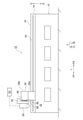
図1から図4に示すように、本発明の実施形態に係るレーザ加工機10は、板材(板金)Wに対してレーザ加工を行う板材加工機(板金加工機)である。以下、本発明の実施形態に係るレーザ加工機10の具体的な構成について説明する。
As shown in FIGS. 1 to 4, the
レーザ加工機10は、Y軸方向(前後方向)に延びた支持体としてのベッド12を具備している。ベッド12の上部には、Y軸方向に延びた一対の端壁14が形成されており、一対の端壁14は、X軸方向に離隔している。また、ベッド12の上部における各端壁14の近傍には、Y軸方向に延びた支持壁16が形成されており、一対の支持壁16は、X軸方向に離隔している。
The
ベッド12の上方(上側)には、レーザ加工を行うための加工領域PFが形成されている。加工領域PFには、スケルトン状のパレット(テーブル)22を介して板材Wが載置される。また、パレット22は、板材Wを点接触で支持する複数の支持プレート(図示省略)を有している。
A processing region PF for performing laser processing is formed above (upper side) the
各支持壁16には、Y軸方向に延びたY軸ガイド部材24が設けられており、一対のY軸ガイド部材24は、加工領域PFを挟んでX軸方向に離隔している。移動体としての門型フレーム(門型の可動フレーム)26は、加工領域PFのX軸方向の両側に位置する一対の支柱部26aと、加工領域PFの上方に位置しかつX軸方向に延びた梁部26bとを有している。そして、門型フレーム26は、一対のY軸ガイド部材24を介してベッド12の上部にY軸方向へ移動可能に設けられている。
Each
レーザ加工機10は、移動体としての門型フレーム26を所定方向であるY軸方向へ移動させる一対のY軸リニアモータ28を具備しており、一対のY軸リニアモータ28は、加工領域PFを挟んでX軸方向に離隔している。また、各Y軸リニアモータ28は、支持壁16に設けられかつY軸方向に延びたモータ固定子30を有しており、各モータ固定子30は、複数の永久磁石により構成されている。各Y軸リニアモータ28は、門型フレーム26の支柱部26aにモータ固定子30と隙間を隔てて対向して設けられたモータ可動子32を有しており、各モータ可動子32は、磁界を発生させるコイルにより構成されている。
The
レーザ加工機10は、門型フレーム26のY軸方向の位置を光学的に検出する一対の光学式のY軸リニアエンコーダ34を具備しており、各Y軸リニアエンコーダ34は、対応するY軸リニアモータ28の近傍に位置している。また、各Y軸リニアエンコーダ34は、端壁14に設けられかつモータ固定子30に平行に延びたリニアスケール36を有しており、リニアスケール36には、同一ピッチの多数の目盛(図示省略)が形成されている。一方(左側)のリニアスケール36は、上向きになっており、他方(右側)のリニアスケール36は、横向きになっている。各Y軸リニアエンコーダ34は、門型フレーム26の支柱部26aにリニアスケール36と間隔を隔てて対向して設けられかつリニアスケール36の目盛を光学的に読み取る読取ヘッド38を有している。
The
ここで、一方のリニアスケール36が端壁14に上向きに設けられているため、リニアスケール36と読取ヘッド38との間隔を所定の微小間隔(例えば0.2mm)に設定した状態で、各リニアエンコーダ34を容易に設置することができる。また、同じ理由により、ベッド12等が熱変形(熱膨張)によって伸びても、リニアスケール36と読取ヘッド38との間隔を所定の微小間隔に保つことができ、各リニアエンコーダ34の動作信頼性を維持することができる。
Here, since one of the
なお、レーザ加工機10は、光学式のY軸リニアエンコーダ34に代えて、門型フレーム26のY軸方向の位置を磁気的に検出する磁気式のY軸リニアエンコーダを用いてもよい。
The
門型フレーム26の梁部26bには、X軸方向に延びたX軸ガイド部材40が設けられており、X軸ガイド部材40には、スライダ42がX軸方向に移動可能に設けられている。また、レーザ加工機10は、スライダ42をX軸方向へ移動させるX軸リニアモータ44を具備している。X軸リニアモータ44は、門型フレーム26の梁部26bに設けられかつX軸方向に延びたモータ固定子46を有しており、複数の永久磁石により構成されている。X軸リニアモータ44は、スライダ42にモータ固定子46と隙間を隔てて対向して設けられたモータ可動子48を有しており、磁界を発生させるコイルにより構成されている。更に、レーザ加工機10は、スライダ42のX軸方向の位置を光学的に検出する光学式のX軸リニアエンコーダ(図示省略)を具備している。
The
スライダ42には、加工領域PFにパレット22を介して載置された板材Wに向かって上方向からレーザ光を照射するレーザ加工ヘッド50が設けられている。また、レーザ加工ヘッド50は、レーザ光を発振するレーザ発振器52に光学的に接続されている。
The
従って、X軸リニアエンコーダの検出値に基づいて、X軸リニアモータ44をフィードバック制御しながら、スライダ42のX軸方向の位置決めを行う。また、各Y軸リニアエンコーダ34の検出値に基づいて、各Y軸リニアモータ28をフィードバック制御しながら、門型フレーム26のY軸方向の位置決めを行う。そして、レーザ加工ヘッド50のX軸方向及びY軸方向の位置決めを行いながら、レーザ加工ヘッド50により板材Wに向かって上方向からレーザ光を照射してレーザ加工を行うことができる。
Therefore, the
前述のように、一方(左側)のリニアスケール36が端壁14に上向きに設けられており、一方のリニアスケール36が長時間に亘って粉塵環境下に置かれると、一方のリニアスケール36上に粉塵が堆積する傾向にある。そのため、門型フレーム26の一方の支柱部26aには、一方のリニアスケール36を清掃するための清掃ノズル54が設けられている。そして、清掃ノズル54及びそれに関連する具体的な構成は、次の通りである。
As described above, one (left side)
図5及び図6(a)(b)に示すように、門型フレーム26の一方の支柱部26aには、清掃ノズル54を構成するアウターノズル管56が設けられている。アウターノズル管56の断面形状は、矩形形状に形成されている。アウターノズル管56の先端部側の軸心56s(清掃ノズル54の先端部側の軸心54s)は、鉛直方向に対して傾斜している。また、アウターノズル管56の先端部側の下部には、先端部側の軸心56sに対して平行な方向から斜めに切欠かれた切欠部56nが形成されている。
As shown in FIGS. 5 and 6A and 6B, an
なお、アウターノズル管56の先端部側の軸心56sは、鉛直方向に対して傾斜しているが、その角度は傾斜しない鉛直方向から、鉛直方向と90°傾いたX軸方向と平行とする角度範囲で適宜選択可能である。また、アウターノズル管56の切欠部56nは、アウターノズル管56の傾き、端壁14(ベッド12)や一方のリニアスケール36との隙間を考慮して、適宜寸法に設定している。更に、アウターノズル管56の断面形状は円形状等の矩形形状以外の形状に形成してもよい。
The
アウターノズル管56の先端部側の内部(内側)には、先端部側の軸心56sに直交する方向に先端板58が設けられている。先端板58の前側端面及び後側端面がアウターノズル管56の内壁面にそれぞれ接合されている。また、先端板58の前側下部及び後側下部には、切欠部58nがそれぞれ形成されている。先端板58の上側端面は、アウターノズル管56の内壁面に非接触になっている。先端板58の下側端面は、アウターノズル管56の切欠部56n側に位置し、かつ清掃ノズル54の先端側から見たときにアウターノズル管56の下側の内壁面に一致している。更に、先端板58の中央部には、後述するインナーノズル62を貫通させるための支持穴60が形成されている。
Inside (inside) the
アウターノズル管56の先端部側の内部(内側)には、インナーノズル管62が設けられており、インナーノズル管62の先端部側は、先端板58の支持穴60に支持された状態で固定されている。インナーノズル管62の基端部側は、アウターノズル管56の外側へ突出している。また、インナーノズル管62の先端部には、読取ヘッド38の近傍であって一方のリニアスケール36の表面に向かって圧縮空気CAを噴出するインナー噴出口64が形成されている。
An
アウターノズル管56の先端部側の内壁面と先端板58の上側端面との間には、読取ヘッド38の近傍であって一方のリニアスケール36の表面の周辺に向かって圧縮空気CAを噴出する第1のアウター噴出口66A(66)が形成されている。また、アウターノズル管56の先端部側の内壁面と先端板58の前側端面及び後側端面との間には、読取ヘッド38の近傍であって一方のリニアスケール36の表面の周辺に向かって圧縮空気CAを噴出する第2のアウター噴出口66B(66)がそれぞれ形成されている。更に、アウターノズル管56の先端部側の内壁面と先端板58の下側端面との間には、鉛直下方(真下)の端壁14に向かって圧縮空気を噴出する第3のアウター噴出口66C(66)が形成されている。
Between the inner wall surface on the tip end side of the
なお、アウターノズル管56の切欠部56nの先端部側の軸心56sに平行な部分を省略して、アウターノズル管56の先端部側の下部にスリット加工を施すことによって第3のアウター噴出口66Cを形成してもよい。アウター噴出口66は、先端板58の全周に亘って形成してもよい。
It should be noted that the third outer ejection port is formed by omitting the portion parallel to the
これにより、インナー噴出口64からの圧縮空気CAによって一方のリニアスケール36上に堆積した粉塵を吹き飛ばす際に、複数のアウター噴出口66(66A,66B,66C)から一方のリニアスケール36の周囲に向かって圧縮空気CAを噴出する。よって、複数のアウター噴出口66(66A,66B,66C)から噴出された圧縮空気CAがインナー噴出口64からの圧縮空気CAの周囲を取り囲む層となり、インナー噴出口64からの圧縮空気CAによる一方のリニアスケール36の周辺の粉塵を含む空気SAの巻き込みを防止でき、一方のリニアスケール36の表面の汚れを防止できる。
As a result, when the dust accumulated on one
特に、第3のアウター噴出口66Cから鉛直下方に向かって噴出した圧縮空気CAは、図6(a)の実線矢印のように一方のリニアスケール36側(右側)のみならず、その反対側(左側)にも分かれように流れができる。よって、図6(a)の点線矢印で示す粉塵を含む空気SAが一方のリニアスケール36側に巻き込まれることを防止するのみならず、粉塵を一方のリニアスケール36から遠ざかる方向へ移動させる効果もあり、一方のリニアスケール36の表面の汚れを十分に防止できる。
In particular, the compressed air CA ejected vertically downward from the third
インナーノズル管62の基端部には、インナーノズル管62に圧縮空気CAを供給するための第1配管68の一端部が接続されている。第1配管68の他端部には、工場設備のエアコンプレッサ等の圧縮空気源(エア源)70に接続されている。また、第1配管68の途中には、インナーノズル管62に供給される圧縮空気CAの流速を調整する第1流速調整手段としての第1スピードコントローラ72が配設されている。第1スピードコントローラ72は、可変流量絞り弁74と、可変流量絞り弁74に並列に接続された逆止弁76とを有している。
One end of a
アウターノズル管56の基端部には、アウターノズル管56に圧縮空気CAを供給するための第2配管78の一端部が接続されている。第2配管78の他端部は、第1配管68の途中における圧縮空気原70と第1スピードコントローラ72との間に接続されている。また、第2配管78の途中には、アウターノズル管56に供給される圧縮空気CAの流速を調整する第2流速調整手段としての第2スピードコントローラ80が配設されている。第2スピードコントローラ80は、可変流量絞り弁82と、可変流量絞り弁82に並列に接続された逆止弁84とを有している。
One end of a
ここで、第1スピードコントローラ72及び第2スピードコントローラ80は、インナー噴出口64からの圧縮空気CAの流速がアウター噴出口66からの圧縮空気CAの流速よりも高くなるように適宜に調整されている。これにより、インナー噴出口64からの流速の速い圧縮空気CAで一方のリニアスケール36の表面上の粉塵を吹き飛ばし、アウターノズル噴出口66からの流速の遅い圧縮空気CAによりエアカーテン効果を生じさせ、一方のリニアスケール36の周辺の粉塵を含む空気SAの巻き込みが抑えられる。
Here, the
続いて、本発明の実施形態の作用及び効果について説明する。 Subsequently, the operation and effect of the embodiment of the present invention will be described.
図4、図5、及び図6(a)に示すように、レーザ加工機10の稼働中に、読取ヘッド38の近傍に設けたインナー噴出口64から一方のリニアスケール36の表面に向かって圧縮空気CAを噴出させる。同時に、読取ヘッド38の近傍に設けた複数のアウター噴出口66から一方のリニアスケール36の表面の周辺に向かって圧縮空気CAを噴出させる。これにより、一方のリニアスケール36が長時間に亘って粉塵環境下に置かれても、インナー噴出口64からの圧縮空気CAによって一方のリニアスケール36上に堆積した粉塵を吹き飛ばすことができる。また、複数のアウター噴出口66からの圧縮空気CAによって一方のリニアスケール36の周辺の粉塵を含む空気SAの巻き込みを抑えることができる。特に、第3のアウター噴出口66Cを含め複数のアウター噴出口66から圧縮空気CAがリニアスケール36の表面の周辺に向かって噴出されるため、エアカーテン効果を発揮させて、一方のリニアスケール36の周辺の粉塵を含む空気SAの巻き込みを十分に抑えることができる。
As shown in FIGS. 4, 5 and 6 (a), compression is performed from the
従って、本発明の実施形態によれば、一方のリニアスケール36を端壁14(ベッド12)に上向きに設けた場合でも、Y軸リニアエンコーダ34によって門型フレーム26のY軸方向の位置を確実かつ正確に検出することができ、門型フレーム26の位置決めを安定的に行うことができる。その結果、本発明の実施形態によれば、板材Wに対して高精度なレーザ加工を安定的に行うことができる。
Therefore, according to the embodiment of the present invention, even when one of the
なお、本発明は、前述の実施形態の説明に限るものでなく、適宜の変更を行うことにより、その他、種々の態様で実施可能である。また、本発明に包含される権利範囲は、前述の実施形態に限定されるものでなく、レーザ加工機10だけでなく、本発明の技術的思想を適用したパンチプレス等の他の板金加工機にも及ぶものである。
The present invention is not limited to the above description of the embodiment, and can be implemented in various other embodiments by making appropriate changes. Further, the scope of rights included in the present invention is not limited to the above-described embodiment, and is not limited to the
本発明の実施例について図7(a)(b)及び図8について説明する。 Examples of the present invention will be described with reference to FIGS. 7 (a) and 7 (b) and FIG.
(実施例1)
インナー噴出口及びアウター噴出口から圧縮空気を噴出させた場合(実施例の場合)において、清掃ノズルの周辺の空気の流線(流線分布)について流体解析を行い、その流体解析の結果をまとめると、図7(a)に示すようになる。また、インナーノズル管のみを清掃ノズルとして用い、インナー噴出口から圧縮空気を噴出させた場合(比較例の場合)において、清掃ノズル(インナーノズル管)の周辺の空気の流線について流体解析を行い、その流体解析の結果をまとめると、図7(b)に示すようになる。なお、圧縮空気の流線は、実線矢印で示し、粉塵を含む空気の流線は、破線矢印で示している。清掃ノズルの内部の空気の流線については省略してある。
(Example 1)
When compressed air is ejected from the inner and outer outlets (in the case of the example), fluid analysis is performed on the streamlines (streamline distribution) of the air around the cleaning nozzle, and the results of the fluid analysis are summarized. As shown in FIG. 7 (a). In addition, when compressed air is ejected from the inner nozzle (in the case of the comparative example) using only the inner nozzle tube as the cleaning nozzle, fluid analysis is performed on the streamline of the air around the cleaning nozzle (inner nozzle tube). The results of the fluid analysis are summarized in FIG. 7 (b). The streamline of compressed air is indicated by a solid arrow, and the streamline of air containing dust is indicated by a broken line arrow. The streamline of air inside the cleaning nozzle is omitted.
即ち、比較例の場合には、リニアスケールの周辺の粉塵を含む空気がインナー噴出口から圧縮空気に巻き込まれて、リニアスケール側に向かって流れることが確認できた。一方、実施例の場合には、リニアスケールの周辺の粉塵を含む空気のリニアスケール側への流れを抑えることが確認できた。これは、アウター噴出口からの圧縮空気によってリニアスケールの周辺の粉塵を含む空気の巻き込みを抑えたことによると考えられる。 That is, in the case of the comparative example, it was confirmed that the air containing dust around the linear scale was entrained in the compressed air from the inner ejection port and flowed toward the linear scale side. On the other hand, in the case of the example, it was confirmed that the flow of air containing dust around the linear scale to the linear scale side was suppressed. It is considered that this is because the compressed air from the outer ejection port suppresses the entrainment of air containing dust around the linear scale.
(実施例2)
実施例の場合及び比較例の場合において、レーザ加工中の粉塵環境を模擬した環境下で清掃試験を行った。そして、その清掃試験の結果をまとめると、図8に示すようになる。なお、清掃試験においては、リニアスケール上に粉塵が堆積し易いようにするため、リニアスケールには上向きの粘着面を有する粘着テープを貼り付けた。
(Example 2)
In the case of the example and the case of the comparative example, the cleaning test was performed in an environment simulating the dust environment during laser processing. The results of the cleaning test are summarized in FIG. In the cleaning test, an adhesive tape having an upward adhesive surface was attached to the linear scale in order to facilitate the accumulation of dust on the linear scale.
即ち、比較例の場合には、リニアスケール上に粉塵が堆積するのに対して、実施例の場合には、リニアスケール上に粉塵が堆積しないことが確認できた。 That is, in the case of the comparative example, it was confirmed that the dust was deposited on the linear scale, whereas in the case of the example, the dust was not deposited on the linear scale.
10 レーザ加工機
12 ベッド(支持体)
14 端壁
16 支持壁
22 パレット
24 Y軸ガイド部材
26 門型フレーム(移動体)
26a 支柱部
26b 梁部
28 Y軸リニアモータ(リニアモータ)
30 モータ固定子
32 モータ可動子
34 Y軸リニアエンコーダ
36 リニアスケール
38 読取ヘッド
40 X軸ガイド部材
42 スライダ
44 X軸リニアモータ
46 モータ固定子
48 モータ可動子
50 レーザ加工ヘッド
52 レーザ発振器
54 清掃ノズル
54s 清掃ノズルの先端部側の軸心
56 アウターノズル管
56s アウターノズル管の先端部側の軸心
56n 切欠部
58 先端板
58n 切欠部
60 支持穴
62 インナーノズル管
64 インナー噴出口
66 アウター噴出口
66A 第1のアウター噴出口
66B 第2のアウター噴出口
66C 第3のアウター噴出口
68 第1配管
70 圧縮空気源(エア源)
72 第1スピードコントローラ
74 可変流量絞り弁
76 逆止弁
78 第2配管
80 第2スピードコントローラ
82 可変流量絞り弁
84 逆止弁
CA 圧縮空気
SA 粉塵を含む空気
PF 加工領域
W 板材(板金)
10
14
30
72
Claims (4)
前記移動体の前記所定方向の位置を検出するリニアエンコーダを構成し、前記支持体に上向きに設けられ、前記所定方向に延びたリニアスケールと、
前記移動体に設けられ、前記リニアスケールに向かって圧縮空気を噴出するインナー噴出口、及び前記リニアスケールの周辺に向かって圧縮空気を噴出するアウター噴出口がそれぞれ形成された清掃ノズルと、を具備し、
前記清掃ノズルは、
前記移動体に設けられたアウターノズル管と、
前記アウターノズル管の先端部側の内部に設けられ、支持穴が貫通して形成された先端板と、
前記アウターノズル管の内部に設けられ、先端部側が前記先端板の前記支持穴に支持されたインナーノズル管と、を有し、
前記インナーノズル管の先端部に前記インナー噴出口が形成され、前記アウターノズル管の先端部側の内壁面と前記先端板の端面との間に前記アウター噴出口が形成されていることを特徴とする板材加工機。 A moving body provided on a support in a plate processing machine that processes a plate material so as to be movable in a predetermined direction, and a moving body.
A linear encoder that detects the position of the moving body in the predetermined direction is configured, and a linear scale that is provided upward on the support and extends in the predetermined direction is used.
It is provided with a cleaning nozzle provided on the moving body and formed with an inner ejection port that ejects compressed air toward the linear scale and an outer ejection outlet that ejects compressed air toward the periphery of the linear scale. And
The cleaning nozzle
The outer nozzle tube provided on the moving body and
A tip plate provided inside the tip side of the outer nozzle tube and formed through a support hole, and a tip plate.
It has an inner nozzle tube provided inside the outer nozzle tube and whose tip end side is supported by the support hole of the tip plate.
The inner spout is formed at the tip of the inner nozzle tube, and the outer spout is formed between the inner wall surface on the tip side of the outer nozzle tube and the end surface of the tip plate. Plate processing machine.
Priority Applications (1)
| Application Number | Priority Date | Filing Date | Title |
|---|---|---|---|
| JP2018058144A JP7002387B2 (en) | 2018-03-26 | 2018-03-26 | Plate processing machine |
Applications Claiming Priority (1)
| Application Number | Priority Date | Filing Date | Title |
|---|---|---|---|
| JP2018058144A JP7002387B2 (en) | 2018-03-26 | 2018-03-26 | Plate processing machine |
Publications (2)
| Publication Number | Publication Date |
|---|---|
| JP2019166556A JP2019166556A (en) | 2019-10-03 |
| JP7002387B2 true JP7002387B2 (en) | 2022-02-04 |
Family
ID=68107069
Family Applications (1)
| Application Number | Title | Priority Date | Filing Date |
|---|---|---|---|
| JP2018058144A Active JP7002387B2 (en) | 2018-03-26 | 2018-03-26 | Plate processing machine |
Country Status (1)
| Country | Link |
|---|---|
| JP (1) | JP7002387B2 (en) |
Citations (1)
| Publication number | Priority date | Publication date | Assignee | Title |
|---|---|---|---|---|
| JP2012232880A (en) | 2011-05-09 | 2012-11-29 | Mitsuboshi Diamond Industrial Co Ltd | Scribe device |
Family Cites Families (2)
| Publication number | Priority date | Publication date | Assignee | Title |
|---|---|---|---|---|
| JPS5068383U (en) * | 1973-10-24 | 1975-06-18 | ||
| JP3859863B2 (en) * | 1998-04-23 | 2006-12-20 | 株式会社アマダ | Plate material positioning device |
-
2018
- 2018-03-26 JP JP2018058144A patent/JP7002387B2/en active Active
Patent Citations (1)
| Publication number | Priority date | Publication date | Assignee | Title |
|---|---|---|---|---|
| JP2012232880A (en) | 2011-05-09 | 2012-11-29 | Mitsuboshi Diamond Industrial Co Ltd | Scribe device |
Also Published As
| Publication number | Publication date |
|---|---|
| JP2019166556A (en) | 2019-10-03 |
Similar Documents
| Publication | Publication Date | Title |
|---|---|---|
| JP6274349B2 (en) | 3D coordinate measuring device | |
| KR20100108200A (en) | Coating device | |
| CN102333615A (en) | Flexure guide bearing for short stroke stage | |
| JP6040382B2 (en) | Mounting device | |
| CN114025900A (en) | Recoater system for additive manufacturing | |
| JP7002387B2 (en) | Plate processing machine | |
| JP6463926B2 (en) | Displacement compensation system for machine tools | |
| JP5337547B2 (en) | Coating device | |
| JP2012169557A (en) | Dicing apparatus | |
| JP6993800B2 (en) | Gate type mobile device and coordinate measuring machine | |
| JP6451942B2 (en) | 3D coordinate measuring device | |
| KR20140071532A (en) | Method for measuring bar-like workpieces radius of curvature of laser machining apparatus for machining bar-like workpieces | |
| JP2007030016A (en) | Laser beam machine | |
| JP6590765B2 (en) | Wire electric discharge machine | |
| JP7351992B1 (en) | position detection device | |
| JP2024051217A (en) | Method of manufacturing rail with built-in scale | |
| KR20140071533A (en) | Method for measuring bar-like workpieces concentric matching of laser machining apparatus for machining bar-like workpieces | |
| KR101276912B1 (en) | Cutting chip scattering prevent apparatus of column moving type machine | |
| JP2008080204A (en) | Paste coating device | |
| JP6729256B2 (en) | Machine Tools | |
| JP5091998B2 (en) | Laser processing machine | |
| KR101828541B1 (en) | Apparatus for mounting a device | |
| JP5319427B2 (en) | Laser processing machine | |
| JPH10277769A (en) | Driving method for laser beam machine and its device | |
| JP3173976B2 (en) | XY table |
Legal Events
| Date | Code | Title | Description |
|---|---|---|---|
| A621 | Written request for application examination |
Free format text: JAPANESE INTERMEDIATE CODE: A621 Effective date: 20201215 |
|
| A131 | Notification of reasons for refusal |
Free format text: JAPANESE INTERMEDIATE CODE: A131 Effective date: 20210914 |
|
| A977 | Report on retrieval |
Free format text: JAPANESE INTERMEDIATE CODE: A971007 Effective date: 20210915 |
|
| A521 | Request for written amendment filed |
Free format text: JAPANESE INTERMEDIATE CODE: A523 Effective date: 20211101 |
|
| TRDD | Decision of grant or rejection written | ||
| A01 | Written decision to grant a patent or to grant a registration (utility model) |
Free format text: JAPANESE INTERMEDIATE CODE: A01 Effective date: 20211207 |
|
| A61 | First payment of annual fees (during grant procedure) |
Free format text: JAPANESE INTERMEDIATE CODE: A61 Effective date: 20211227 |
|
| R150 | Certificate of patent or registration of utility model |
Ref document number: 7002387 Country of ref document: JP Free format text: JAPANESE INTERMEDIATE CODE: R150 |