JP6997511B2 - Bicycle wheel parts with a braking area made of composite material and their manufacturing methods - Google Patents
Bicycle wheel parts with a braking area made of composite material and their manufacturing methods Download PDFInfo
- Publication number
- JP6997511B2 JP6997511B2 JP2016197611A JP2016197611A JP6997511B2 JP 6997511 B2 JP6997511 B2 JP 6997511B2 JP 2016197611 A JP2016197611 A JP 2016197611A JP 2016197611 A JP2016197611 A JP 2016197611A JP 6997511 B2 JP6997511 B2 JP 6997511B2
- Authority
- JP
- Japan
- Prior art keywords
- bicycle wheel
- braking
- braking area
- bicycle
- region
- Prior art date
- Legal status (The legal status is an assumption and is not a legal conclusion. Google has not performed a legal analysis and makes no representation as to the accuracy of the status listed.)
- Active
Links
Images


Classifications
-
- B—PERFORMING OPERATIONS; TRANSPORTING
- B60—VEHICLES IN GENERAL
- B60B—VEHICLE WHEELS; CASTORS; AXLES FOR WHEELS OR CASTORS; INCREASING WHEEL ADHESION
- B60B5/00—Wheels, spokes, disc bodies, rims, hubs, wholly or predominantly made of non-metallic material
- B60B5/02—Wheels, spokes, disc bodies, rims, hubs, wholly or predominantly made of non-metallic material made of synthetic material
-
- B—PERFORMING OPERATIONS; TRANSPORTING
- B23—MACHINE TOOLS; METAL-WORKING NOT OTHERWISE PROVIDED FOR
- B23K—SOLDERING OR UNSOLDERING; WELDING; CLADDING OR PLATING BY SOLDERING OR WELDING; CUTTING BY APPLYING HEAT LOCALLY, e.g. FLAME CUTTING; WORKING BY LASER BEAM
- B23K26/00—Working by laser beam, e.g. welding, cutting or boring
- B23K26/36—Removing material
- B23K26/40—Removing material taking account of the properties of the material involved
- B23K26/402—Removing material taking account of the properties of the material involved involving non-metallic material, e.g. isolators
-
- B—PERFORMING OPERATIONS; TRANSPORTING
- B29—WORKING OF PLASTICS; WORKING OF SUBSTANCES IN A PLASTIC STATE IN GENERAL
- B29C—SHAPING OR JOINING OF PLASTICS; SHAPING OF MATERIAL IN A PLASTIC STATE, NOT OTHERWISE PROVIDED FOR; AFTER-TREATMENT OF THE SHAPED PRODUCTS, e.g. REPAIRING
- B29C69/00—Combinations of shaping techniques not provided for in a single one of main groups B29C39/00 - B29C67/00, e.g. associations of moulding and joining techniques; Apparatus therefore
- B29C69/001—Combinations of shaping techniques not provided for in a single one of main groups B29C39/00 - B29C67/00, e.g. associations of moulding and joining techniques; Apparatus therefore a shaping technique combined with cutting, e.g. in parts or slices combined with rearranging and joining the cut parts
-
- B—PERFORMING OPERATIONS; TRANSPORTING
- B60—VEHICLES IN GENERAL
- B60B—VEHICLE WHEELS; CASTORS; AXLES FOR WHEELS OR CASTORS; INCREASING WHEEL ADHESION
- B60B1/00—Spoked wheels; Spokes thereof
-
- B—PERFORMING OPERATIONS; TRANSPORTING
- B60—VEHICLES IN GENERAL
- B60B—VEHICLE WHEELS; CASTORS; AXLES FOR WHEELS OR CASTORS; INCREASING WHEEL ADHESION
- B60B1/00—Spoked wheels; Spokes thereof
- B60B1/003—Spoked wheels; Spokes thereof specially adapted for bicycles
-
- B—PERFORMING OPERATIONS; TRANSPORTING
- B60—VEHICLES IN GENERAL
- B60B—VEHICLE WHEELS; CASTORS; AXLES FOR WHEELS OR CASTORS; INCREASING WHEEL ADHESION
- B60B21/00—Rims
-
- B—PERFORMING OPERATIONS; TRANSPORTING
- B60—VEHICLES IN GENERAL
- B60B—VEHICLE WHEELS; CASTORS; AXLES FOR WHEELS OR CASTORS; INCREASING WHEEL ADHESION
- B60B21/00—Rims
- B60B21/08—Rims characterised by having braking surfaces
-
- B—PERFORMING OPERATIONS; TRANSPORTING
- B23—MACHINE TOOLS; METAL-WORKING NOT OTHERWISE PROVIDED FOR
- B23K—SOLDERING OR UNSOLDERING; WELDING; CLADDING OR PLATING BY SOLDERING OR WELDING; CUTTING BY APPLYING HEAT LOCALLY, e.g. FLAME CUTTING; WORKING BY LASER BEAM
- B23K2103/00—Materials to be soldered, welded or cut
- B23K2103/16—Composite materials, e.g. fibre reinforced
- B23K2103/166—Multilayered materials
- B23K2103/172—Multilayered materials wherein at least one of the layers is non-metallic
-
- B—PERFORMING OPERATIONS; TRANSPORTING
- B23—MACHINE TOOLS; METAL-WORKING NOT OTHERWISE PROVIDED FOR
- B23K—SOLDERING OR UNSOLDERING; WELDING; CLADDING OR PLATING BY SOLDERING OR WELDING; CUTTING BY APPLYING HEAT LOCALLY, e.g. FLAME CUTTING; WORKING BY LASER BEAM
- B23K2103/00—Materials to be soldered, welded or cut
- B23K2103/50—Inorganic material, e.g. metals, not provided for in B23K2103/02 – B23K2103/26
-
- B—PERFORMING OPERATIONS; TRANSPORTING
- B29—WORKING OF PLASTICS; WORKING OF SUBSTANCES IN A PLASTIC STATE IN GENERAL
- B29K—INDEXING SCHEME ASSOCIATED WITH SUBCLASSES B29B, B29C OR B29D, RELATING TO MOULDING MATERIALS OR TO MATERIALS FOR MOULDS, REINFORCEMENTS, FILLERS OR PREFORMED PARTS, e.g. INSERTS
- B29K2105/00—Condition, form or state of moulded material or of the material to be shaped
- B29K2105/06—Condition, form or state of moulded material or of the material to be shaped containing reinforcements, fillers or inserts
- B29K2105/08—Condition, form or state of moulded material or of the material to be shaped containing reinforcements, fillers or inserts of continuous length, e.g. cords, rovings, mats, fabrics, strands or yarns
-
- B—PERFORMING OPERATIONS; TRANSPORTING
- B29—WORKING OF PLASTICS; WORKING OF SUBSTANCES IN A PLASTIC STATE IN GENERAL
- B29K—INDEXING SCHEME ASSOCIATED WITH SUBCLASSES B29B, B29C OR B29D, RELATING TO MOULDING MATERIALS OR TO MATERIALS FOR MOULDS, REINFORCEMENTS, FILLERS OR PREFORMED PARTS, e.g. INSERTS
- B29K2307/00—Use of elements other than metals as reinforcement
- B29K2307/04—Carbon
-
- B—PERFORMING OPERATIONS; TRANSPORTING
- B29—WORKING OF PLASTICS; WORKING OF SUBSTANCES IN A PLASTIC STATE IN GENERAL
- B29L—INDEXING SCHEME ASSOCIATED WITH SUBCLASS B29C, RELATING TO PARTICULAR ARTICLES
- B29L2031/00—Other particular articles
- B29L2031/30—Vehicles, e.g. ships or aircraft, or body parts thereof
- B29L2031/3091—Bicycles
-
- B—PERFORMING OPERATIONS; TRANSPORTING
- B29—WORKING OF PLASTICS; WORKING OF SUBSTANCES IN A PLASTIC STATE IN GENERAL
- B29L—INDEXING SCHEME ASSOCIATED WITH SUBCLASS B29C, RELATING TO PARTICULAR ARTICLES
- B29L2031/00—Other particular articles
- B29L2031/32—Wheels, pinions, pulleys, castors or rollers, Rims
-
- B—PERFORMING OPERATIONS; TRANSPORTING
- B60—VEHICLES IN GENERAL
- B60B—VEHICLE WHEELS; CASTORS; AXLES FOR WHEELS OR CASTORS; INCREASING WHEEL ADHESION
- B60B1/00—Spoked wheels; Spokes thereof
- B60B1/02—Wheels with wire or other tension spokes
-
- B—PERFORMING OPERATIONS; TRANSPORTING
- B60—VEHICLES IN GENERAL
- B60B—VEHICLE WHEELS; CASTORS; AXLES FOR WHEELS OR CASTORS; INCREASING WHEEL ADHESION
- B60B1/00—Spoked wheels; Spokes thereof
- B60B1/06—Wheels with compression spokes
-
- B—PERFORMING OPERATIONS; TRANSPORTING
- B60—VEHICLES IN GENERAL
- B60B—VEHICLE WHEELS; CASTORS; AXLES FOR WHEELS OR CASTORS; INCREASING WHEEL ADHESION
- B60B2310/00—Manufacturing methods
- B60B2310/20—Shaping
- B60B2310/204—Shaping by moulding, e.g. injection moulding, i.e. casting of plastics material
-
- B—PERFORMING OPERATIONS; TRANSPORTING
- B60—VEHICLES IN GENERAL
- B60B—VEHICLE WHEELS; CASTORS; AXLES FOR WHEELS OR CASTORS; INCREASING WHEEL ADHESION
- B60B2310/00—Manufacturing methods
- B60B2310/20—Shaping
- B60B2310/228—Shaping by machining
-
- B—PERFORMING OPERATIONS; TRANSPORTING
- B60—VEHICLES IN GENERAL
- B60B—VEHICLE WHEELS; CASTORS; AXLES FOR WHEELS OR CASTORS; INCREASING WHEEL ADHESION
- B60B2310/00—Manufacturing methods
- B60B2310/60—Surface treatment; After treatment
-
- B—PERFORMING OPERATIONS; TRANSPORTING
- B60—VEHICLES IN GENERAL
- B60B—VEHICLE WHEELS; CASTORS; AXLES FOR WHEELS OR CASTORS; INCREASING WHEEL ADHESION
- B60B2360/00—Materials; Physical forms thereof
- B60B2360/30—Synthetic materials
- B60B2360/34—Reinforced plastics
- B60B2360/341—Reinforced plastics with fibres
-
- B—PERFORMING OPERATIONS; TRANSPORTING
- B60—VEHICLES IN GENERAL
- B60B—VEHICLE WHEELS; CASTORS; AXLES FOR WHEELS OR CASTORS; INCREASING WHEEL ADHESION
- B60B2900/00—Purpose of invention
- B60B2900/10—Reduction of
- B60B2900/115—Complexity
-
- B—PERFORMING OPERATIONS; TRANSPORTING
- B60—VEHICLES IN GENERAL
- B60B—VEHICLE WHEELS; CASTORS; AXLES FOR WHEELS OR CASTORS; INCREASING WHEEL ADHESION
- B60B2900/00—Purpose of invention
- B60B2900/10—Reduction of
- B60B2900/131—Vibrations
-
- B—PERFORMING OPERATIONS; TRANSPORTING
- B60—VEHICLES IN GENERAL
- B60B—VEHICLE WHEELS; CASTORS; AXLES FOR WHEELS OR CASTORS; INCREASING WHEEL ADHESION
- B60B2900/00—Purpose of invention
- B60B2900/10—Reduction of
- B60B2900/133—Noise
-
- B—PERFORMING OPERATIONS; TRANSPORTING
- B60—VEHICLES IN GENERAL
- B60B—VEHICLE WHEELS; CASTORS; AXLES FOR WHEELS OR CASTORS; INCREASING WHEEL ADHESION
- B60B2900/00—Purpose of invention
- B60B2900/30—Increase in
- B60B2900/325—Reliability
-
- B—PERFORMING OPERATIONS; TRANSPORTING
- B60—VEHICLES IN GENERAL
- B60B—VEHICLE WHEELS; CASTORS; AXLES FOR WHEELS OR CASTORS; INCREASING WHEEL ADHESION
- B60B3/00—Disc wheels, i.e. wheels with load-supporting disc body
-
- B—PERFORMING OPERATIONS; TRANSPORTING
- B60—VEHICLES IN GENERAL
- B60Y—INDEXING SCHEME RELATING TO ASPECTS CROSS-CUTTING VEHICLE TECHNOLOGY
- B60Y2200/00—Type of vehicle
- B60Y2200/10—Road Vehicles
- B60Y2200/13—Bicycles; Tricycles
-
- B—PERFORMING OPERATIONS; TRANSPORTING
- B62—LAND VEHICLES FOR TRAVELLING OTHERWISE THAN ON RAILS
- B62L—BRAKES SPECIALLY ADAPTED FOR CYCLES
- B62L1/00—Brakes; Arrangements thereof
- B62L1/02—Brakes; Arrangements thereof in which cycle wheels are engaged by brake elements
- B62L1/06—Brakes; Arrangements thereof in which cycle wheels are engaged by brake elements the wheel rim being engaged
- B62L1/10—Brakes; Arrangements thereof in which cycle wheels are engaged by brake elements the wheel rim being engaged by the elements moving substantially parallel to the wheel axis
Description
本発明は、制動体と協働するように構成された少なくとも1つの制動エリアを有する自転車又は同様の乗り物の車輪用部品であって、前記制動エリアが実質的に複合材料からなる、車輪用部品に関する。本発明は、さらに、そのような車輪用部品を製造する方法に関する。 The present invention is a wheel component of a bicycle or similar vehicle having at least one braking area configured to cooperate with a braking body, wherein the braking area is substantially made of a composite material. Regarding. The present invention further relates to a method of manufacturing such a wheel component.
自転車では、車輪の減速又は制動が様々な方法で行われる。この様々な方法には、パッドを保持するジョーでリム付近を挟み込む(具体的に言うと、該ジョーでリムの両側の側壁を挟み込み、より一般的に言うと、該ジョーで車輪の周縁部付近を挟み込む)ことによる方法[リムブレーキ]や、パッドを車輪のハブに固定的に連結したディスクに押し付けることによる方法[ディスクブレーキ]が含まれる。 On a bicycle, deceleration or braking of the wheels is done in various ways. In these various methods, the jaws holding the pads pinch the vicinity of the rim (specifically, the jaws pinch the side walls on both sides of the rim, and more generally, the jaws pinch the periphery of the wheel. The method [rim brake] and the method [disc brake] by pressing the pad against the disc fixedly connected to the hub of the wheel are included.
本明細書および添付の特許請求の範囲において「制動体」とは、パッドを指すものとする。 As used herein and in the appended claims, "braking body" shall refer to the pad.
本明細書および添付の特許請求の範囲において「車輪用部品」とは、スポーク車輪のリム、ディスクホイールのリムもしくは周縁部、スパイダーホイールのリムもしくは周縁部、またはディスクブレーキのディスクを指すものとする。 As used herein and in the context of the accompanying patent claims, "wheel component" shall mean the rim of a spoke wheel, the rim or rim of a disc wheel, the rim or rim of a spider wheel, or the disc of a disc brake. ..
周知のとおり、具体的には、スポーク車輪のリムは、径方向外側で自転車車輪のタイヤと連結し、径方向内側で自転車車輪の複数のスポーク(これらのスポークは、さらに、車輪のハブと連結される)と連結するように設計された環状の本体を備える。典型的に、リムのこの環状の本体は、両側の側壁を有する。これらの側壁には、自転車のブレーキのパッドが働きかけるブレーキトラック又はブレーキエリアが設けられる。 As is well known, specifically, the spoke wheel rims connect to the bicycle wheel tires radially outward and multiple spokes of the bicycle wheel radially inside (these spokes also connect to the wheel hub). Includes an annular body designed to connect with). Typically, this annular body of the rim has side walls on both sides. These side walls are provided with brake tracks or brake areas on which the bicycle brake pads act.
本明細書および添付の特許請求の範囲において「複合材料」とは、高分子材料(「マトリクス」又は「樹脂」と称されることがある)内に包埋された構造繊維を含む材料を指すものとする。 As used herein and in the appended claims, "composite material" refers to materials containing structural fibers embedded within a polymeric material (sometimes referred to as "matrix" or "resin"). It shall be.
高分子材料は、熱可塑性材料であってもよいし熱硬化性材料であってもよい。 The polymer material may be a thermoplastic material or a thermosetting material.
典型的に、構造繊維は、カーボン繊維および/またはガラス繊維および/またはアラミド繊維および/またはセラミック繊維および/またはボロン繊維および/またはこれらの組合せを含む。このような強化繊維の幾何形状は、マトリクス内にランダムに配置された極めて短い繊維から、多かれ少なかれ規則的に(例えば、平行な束の形状および/または二方向に織られた形状および/また織られていない二方向の形状および/またはこれらの組合せで)配置された多かれ少なかれ長めの繊維まで、極めて多種多様である。典型的に、複合材料からなる部品は、熱硬化性高分子材料の場合には圧縮成形により製造され、熱可塑性高分子材料の場合には射出成形により製造される。出発材料も多種多様な形態を取ることができ、例えば乾燥した繊維を含むもの、高分子材料で予備含浸された繊維を含むもの等が挙げられる。後者の予備含浸された繊維は、ゆるい集合体からなる「マット」の形態、あるいは、集合体からなる「マット」の形態であり得る。「集合体」とは、繊維セグメントからなる実質上二次元の小片または三次元の小片であって、通常その内部において該繊維セグメントが互いに平行に、あるいは、織構造に従って配置されている、繊維セグメントからなる実質上二次元の小片または三次元の小片を指すものとする。「マット」とは、幅寸法および長さ寸法に対して厚さが無視可能な程度のものである出発材料のことを意味する。 Typically, structural fibers include carbon fibers and / or glass fibers and / or aramid fibers and / or ceramic fibers and / or boron fibers and / or combinations thereof. The geometry of such reinforcing fibers can be more or less regularly (eg, parallel bundle shapes and / or bidirectionally woven shapes and / or weaves) from very short fibers randomly arranged in the matrix. There is a great variety, from non-bidirectional shapes and / or arrangements of more or less long fibers (in combinations thereof). Typically, a component made of a composite material is manufactured by compression molding in the case of a thermosetting polymer material and by injection molding in the case of a thermoplastic polymer material. The starting material can also take a wide variety of forms, including those containing dried fibers, those containing pre-impregnated fibers with a polymeric material, and the like. The latter pre-impregnated fiber can be in the form of a "mat" consisting of loose aggregates or in the form of a "mat" consisting of aggregates. An "aggregate" is a substantially two-dimensional or three-dimensional piece of fiber segment in which the fiber segments are usually arranged parallel to each other or according to a woven structure. It shall refer to a substantially two-dimensional piece or a three-dimensional piece consisting of. By "mat" is meant a starting material whose thickness is negligible with respect to width and length dimensions.
複合材料からなる自転車車輪用部品には、高い剛性及び機械強度と軽量性とを兼ね備えるという利点がある。 Bicycle wheel parts made of composite materials have the advantages of high rigidity, mechanical strength and light weight.
特許文献1には、カーボンの表面(例えば、離型材及びエポキシ外層が摩耗した際に、短期間のブレーキ使用で露出するカーボン繊維リムのカーボン表面)は、耐摩耗性、摩擦性能向上機能に比較的乏しく、よってカーボン繊維の表面は繊維強化プラスチック(FRP)リムのブレーキトラックとして一般的に適切でないと記載されている。これに鑑みて特許文献1には、径方向外側のタイヤ係合部と、径方向内側のスポーク係合部と、離間して配置され、前記径方向外側のタイヤ係合部よりも内方に延在する第1の側壁及び第2の側壁と、前記第1及び第2の側壁に配置されたブレーキトラックとを備える自転車用リムであって、該ブレーキトラックが、例えば高硬度・高熱伝導率・高耐熱性の微小球粒(例えば、炭化ケイ素、窒化ケイ素、炭化ホウ素、セラミック、金属の微粒子)などの、非繊維状微粒子の層を含む、自転車用リムが開示されている。これらの粒子は、エポキシ樹脂中に包埋されており、好ましくは、部分的に包埋され、部分的に露出している。エポキシ樹脂に対する微粒子の割合としては、約5~60重量%が摩擦性微粒子であることが好ましい。製造方法は、高温高靭性エポキシ樹脂の層内に完全に又は部分的に懸濁された炭化ケイ素等の非繊維状微粒子のトラックをFRPリムに適用した後、該ブレーキトラックから一定量のエポキシを除去し、該ブレーキトラックの摩擦係数及び表面トポグラフィを微調整することを含む。このようにして、このFRPを雨天時制動に最適化することができる。具体的に述べると、特許文献1では、リムの硬化後に余剰の樹脂を除去することにより、リムは上記微粒子を露出するようにブレーキトラックのエポキシ最外部が取り除かれた状態となる。特許文献1によれば、この工程は必須ではないものの、新品のカーボン繊維リムの雨天時制動性能は通常乏しく、ブレーキパッドのエポキシがゆっくりと摩耗し、包埋された微粒子が露出することにより、表面がなじむまでには数週間かかり得るとのことである。そのため、微粒子を被覆するエポキシがブラスト摩耗処理により、軽く摩耗除去される。このブラスト処理は、エポキシ樹脂より硬質であるが、ブレーキの表面に埋め込まれた摩耗性粒子より硬度の低いガーネットなどの媒体を用いることにより微調整できる。 In Patent Document 1, the surface of carbon (for example, the carbon surface of a carbon fiber rim exposed by using a brake for a short period of time when the release material and the epoxy outer layer are worn) is compared with the function of improving wear resistance and friction performance. It is described as poor and therefore the carbon fiber surface is generally not suitable as a brake track for fiber reinforced plastic (FRP) rims. In view of this, in Patent Document 1, the tire engaging portion on the outer side in the radial direction and the spoke engaging portion on the inner side in the radial direction are arranged apart from each other, and are arranged inward from the tire engaging portion on the outer side in the radial direction. A bicycle rim including an extending first side wall and a second side wall, and a brake track arranged on the first and second side walls, wherein the brake track has, for example, high hardness and high thermal conductivity. Disclosed are bicycle rims that include a layer of non-fibrous microparticles such as highly heat resistant microspheres (eg, silicon carbide, silicon nitride, boron carbide, ceramic, metal microparticles). These particles are embedded in an epoxy resin, preferably partially embedded and partially exposed. The ratio of the fine particles to the epoxy resin is preferably about 5 to 60% by weight, which is preferably frictional fine particles. The manufacturing method is to apply a track of non-fibrous fine particles such as silicon carbide completely or partially suspended in a layer of high temperature and high toughness epoxy resin to the FRP rim, and then apply a certain amount of epoxy from the brake track. It involves removing and fine-tuning the coefficient of friction and surface topography of the brake track. In this way, this FRP can be optimized for braking in the rain. Specifically, in Patent Document 1, by removing the excess resin after the rim is cured, the rim is in a state where the outermost epoxy of the brake truck is removed so as to expose the fine particles. According to Patent Document 1, although this step is not essential, the braking performance of a new carbon fiber rim in rainy weather is usually poor, and the epoxy of the brake pad is slowly worn to expose the embedded fine particles. It can take several weeks for the surface to become familiar. Therefore, the epoxy covering the fine particles is lightly abraded and removed by the blast wear treatment. This blasting process is harder than epoxy resin, but can be fine-tuned by using a medium such as garnet, which is harder than the wearable particles embedded in the surface of the brake.
出願人の見たところでは、微粒子の添加は、加工の再現性を低下させるだけではなく、加工コストおよび加工時間の増加という点でも好ましくない。 From the applicant's point of view, the addition of fine particles is not preferable in terms of not only reducing the reproducibility of processing but also increasing the processing cost and processing time.
特許文献2は、少なくとも1つのフランク上に、制動部材を配するための少なくとも1つの制動エリアを備えた自転車等のリムを開示している。前記制動エリアは、実質的に半仕上げされた強化繊維シート製品の形をとる繊維強化プラスチックからなり、制動エリア表面の10%超、90%以下を、露出した強化繊維が占め、強化繊維は、該制動エリアの材料の除去により露出している。
この文献によれば、圧縮成形の結果、制動エリア表面に押し出された余剰の高分子材料は、鋼製又はアルミニウム製のリムとの摩耗の上で難点となる。アルミニウム層又はアルミニウム製部品を適用することなく、電解めっきに頼ることなく、また追加の硬質材料を適用することなくこれを回避するため、特許文献2は、ブレーキトラック全体にわたって、チップ除去加工、つまり切削工具を用いた加工、または腐食加工を行うことにより、表面の高分子材料を除去し、繊維部分を露出させることを記載している。特許文献2によれば、リムは、繊維の物理的特性によって主に決定される顕著な特性、例えば、良好な制動性、低摩耗性(表面の摩耗は極めて小さく、主としてゴム製のブレーキライニングに限定される)、良好な熱伝導性(ブレーキの作動による熱の良好な除去)等を得るとのことである。さらに、濡れた時の挙動を向上させるため、溝を設けてもよい。特許文献2は、層状材とは異なる複合材料の使用も想定している。
According to this document, the excess polymer material extruded to the braking area surface as a result of compression molding is a drawback in terms of wear with steel or aluminum rims. In order to avoid this without applying an aluminum layer or aluminum parts, without resorting to electroplating, and without applying additional hard materials,
特許文献3は、上記の解決手段のように、切削工具を用いた加工は、強化繊維に損傷を与え、結果としてリムの弱体化を招くことを認め、上記の解決手段では、表面により多くの繊維を有する材料を使用する必要があり、これをのちに除去するため、材料の無駄を生じリムの重量も増加することに着眼した。実質的に軽量の複合材料からなる少なくとも1つの制動エリアをリムに付与してこの欠点を克服するため、特許文献3は、(具体的には数値制御機械CNCを用い、より具体的には赤外線レーザを用いたレーザ切削加工により、より一般的にはフライス加工、旋削加工、充填加工または剥離加工を用いて)制動エリアの少なくとも一部を加工し、制動特性、特に濡れ時の制動特性を改善するために巨視的な表面構造を形成することを記載している。 Patent Document 3 recognizes that machining with a cutting tool, as in the above-mentioned solution, damages the reinforcing fibers, resulting in weakening of the rim, and in the above-mentioned solution, more on the surface. It was necessary to use a material with fibers, which was later removed, which resulted in wasted material and increased rim weight. In order to overcome this drawback by imparting at least one braking area made of a substantially lightweight composite material to the rim, Patent Document 3 (specifically, using a numerical control machine CNC, more specifically infrared). Laser cutting with a laser, more generally using milling, turning, filling or peeling) to machine at least part of the braking area and improve braking characteristics, especially when wet. It describes forming a macroscopic surface structure in order to do so.
特にこのマクロ構造は、制動エリアにおける水の膜を途切れさせるか又は吸い取るように意図されており、具体的には、少なくとも一部径方向に従って延在し、かつ/またはリム外部へ開口するように延在する幅狭な空洞を含んでいる。これらの空洞は、繊維の機械的特性を損なわないためには樹脂のみに形成されることが好ましいが、逆に繊維のみに形成されてもよいし、複合材料の両方の材料に形成されたものであってもよい。これらの空洞は、長方形、三角形、丸みを帯びた形状の断面またはその他の形状の断面を有するものであってもよい。あるいは、上記マクロ構造は、略長方形状の部分を構成するものであってもよいし、環状の制動エリアの一象限または全体を占めるものであってもよい。特許文献3には、さらに、不規則なマクロ構造の使用、例えば、非周期的なマクロ構造および/またはリムにおける2つのフランク上で互いに異なるマクロ構造を使用することにより、共鳴の現象を回避することが教示されている。リムには、一方又は両方のフランクにおいて1、または2以上の制動エリアが設けられてもよい。マクロ構造が、1つの制動エリアのみに又はその一部のみに形成されてもよい。さらに、制動エリアは、ディスクホイールのディスクに形成されてもよいし、ブレーキのディスクに形成されてもよい。 In particular, this macrostructure is intended to disrupt or absorb a film of water in the braking area, specifically extending at least partly along the radial direction and / or opening to the outside of the rim. It contains an extending narrow cavity. These cavities are preferably formed only in the resin so as not to impair the mechanical properties of the fibers, but conversely they may be formed only in the fibers or in both materials of the composite material. May be. These cavities may have a rectangular, triangular, rounded cross section or other shaped cross section. Alternatively, the macro structure may constitute a substantially rectangular portion, or may occupy one quadrant or the entire annular braking area. Patent Document 3 further avoids the phenomenon of resonance by using irregular macrostructures, eg, aperiodic macrostructures and / or macrostructures that differ from each other on two flanks in the rim. Is taught. The rim may be provided with one or more braking areas on one or both flanks. The macro structure may be formed in only one braking area or only a part thereof. Further, the braking area may be formed on the disc of the disc wheel or the disc of the brake.
この文献では、何よりも特に、複合材料から特定の材料(特には、樹脂)の選択的除去が可能となり、より良好な摩擦係数(特に、雨天時の制動)が得られるよう制御が可能となることからレーザ加工が好ましいとしている。しかも、レーザ加工は、車輪の構造を弱めることなく、空洞により大きな表面を付与することができる。レーザで表面の樹脂のみを除去することにより、カーボン繊維布帛の外観は依然視認できる。特許文献3によれば、表面は、加工前のように滑らかでもなければ、切削工具で加工したときのように粗くもなく、なだらかな起伏を持ち、樹脂の除去により、僅かに窪んだ部位と、僅かに盛り上がった部位が形成されるので、その構造は視覚や触覚によって認識できる。特許文献3は、樹脂を透過しないレーザ、好ましくは、遠赤外領域のCO2レーザ(例えば、発振波長が約10.6ミクロンのもの)を選択することを教示しており、さらに、樹脂の燃焼温度(400℃~600℃の間)とカーボン繊維の燃焼温度(1500℃超)の相違から、カーボン繊維がレーザにより影響されないようにレーザを調節することが可能であると記載している。また、特許文献3では、実際のところ、樹脂の表面厚さを正確に定めることは不可能であると認識され、そこで80%以上の樹脂が除去され、損傷又は切断されるカーボン繊維が20%以下になるようにレーザを調節することが示されている。 Above all, in this document, it is possible to selectively remove a specific material (particularly a resin) from a composite material and control it to obtain a better coefficient of friction (particularly braking in rainy weather). Therefore, laser processing is preferable. Moreover, laser machining can impart a larger surface to the cavity without weakening the structure of the wheel. By removing only the resin on the surface with a laser, the appearance of the carbon fiber fabric is still visible. According to Patent Document 3, the surface is not as smooth as before machining, is not rough as when machined with a cutting tool, has gentle undulations, and is slightly recessed due to the removal of resin. Since a slightly raised part is formed, its structure can be recognized visually or tactilely. Patent Document 3 teaches to select a laser that does not transmit the resin, preferably a CO 2 laser in the far infrared region (for example, one having an oscillation wavelength of about 10.6 microns), and further, the resin. Due to the difference between the combustion temperature (between 400 ° C and 600 ° C) and the combustion temperature of the carbon fiber (over 1500 ° C), it is stated that the laser can be adjusted so that the carbon fiber is not affected by the laser. Further, in Patent Document 3, it is recognized that it is actually impossible to accurately determine the surface thickness of the resin, in which 80% or more of the resin is removed, and 20% of the carbon fibers are damaged or cut. It has been shown to adjust the laser to:
しかし出願人の認めたところ、特許文献3の加工では、十分に広い領域が加工されると、形成される表面は制動時に騒音を生じかねないものとなり、他方、個別に分離した空洞が加工された場合には、乾燥気候時に良好な制動性能が得られるとは考えられない。 However, according to the applicant's approval, in the processing of Patent Document 3, if a sufficiently wide area is processed, the formed surface may generate noise during braking, while individually separated cavities are processed. In such cases, it is unlikely that good braking performance will be obtained in dry weather.
本発明の基本的な技術的課題は、出発材料となる複合材料の強度を維持しつつ、良好な晴天時制動性、良好な雨天時制動性などの良好な制動特性、特に制動時間の観点から、および騒音の抑制または無音化の観点からの良好な制動特性を付与する、自転車車輪用部品およびその製造方法を提供し、並びに製造プロセスにかかるコストおよび/または工程の複雑化をできるかぎり抑制することにある。 The basic technical problem of the present invention is to maintain the strength of the composite material as a starting material, and from the viewpoint of good braking characteristics such as good braking performance in fine weather and good braking performance in rainy weather, especially from the viewpoint of braking time. , And provide bicycle wheel parts and methods of manufacture thereof that provide good braking characteristics from the standpoint of noise suppression or noise reduction, and minimize the cost and / or process complexity of the manufacturing process. There is something in it.
本発明の一つの構成は、自転車車輪用部品の製造方法に関し、該方法は、
制動体と協働するように構成された少なくとも1つの制動エリアを有し、該制動エリアが、高分子材料内に包埋された構造繊維を含む複合材料を成形することによって形成された自転車車輪用部品
を供給する工程(a)と、
前記少なくとも1つの制動エリアの少なくとも1つの領域の、成形後加工を行う工程(b)とを備え、該工程(b)が、
前記領域全体から、前記構造繊維を除去せず高分子材料のみを、前記構造繊維が少なくとも一部前記高分子材料から露出するように除去するステップ(b1)と、
前記構造繊維又は、前記構造繊維及び前記高分子材料を、前記領域内の少なくとも1つの溝に従って除去するステップ(b2)と、
を含む、方法である。
One configuration of the present invention relates to a method for manufacturing a bicycle wheel component, which method is:
A bicycle wheel having at least one braking area configured to cooperate with the braking body, the braking area formed by molding a composite material containing structural fibers embedded within a polymer material. The process of supplying parts (a) and
A step (b) of performing post-molding processing in at least one region of the at least one braking area is provided, and the step (b) comprises a step (b).
The step (b1) of removing only the polymer material from the entire region without removing the structural fibers so that at least a part of the structural fibers is exposed from the polymer material.
The step (b2) of removing the structural fiber or the structural fiber and the polymer material according to at least one groove in the region.
Is a method, including.
前記供給工程(a)は、前記自転車用部品の全体を複合材料により成形するプロセスを含むことが好ましい。 The supply step (a) preferably includes a process of molding the entire bicycle component with a composite material.
前記ステップ(b2)において、前記構造繊維は、意図的に切断されることが好ましい。 In the step (b2), it is preferable that the structural fiber is intentionally cut.
前記ステップ(b2)は、溝のなすパターンまたはらせん状の溝に従って行われることが好ましい。 The step (b2) is preferably performed according to the pattern formed by the grooves or the spiral groove.
前記ステップ(b2)は、ステップ(b1)の後に行われることが好ましい。 The step (b2) is preferably performed after the step (b1).
前記ステップ(b1)および/またはステップ(b2)は、熱分解により行われることが好ましい。 The steps (b1) and / or steps (b2) are preferably performed by thermal decomposition.
前記ステップ(b1)および/またはステップ(b2)は、レーザビームを介した熱分解により行われることがより好ましく、これには近赤外領域のレーザを用いることがさらに好ましい。 It is more preferable that the step (b1) and / or the step (b2) is performed by thermal decomposition via a laser beam, and it is further preferable to use a laser in the near infrared region.
ステップ(b1)およびステップ(b2)は、同一のレーザ光源により発せられるレーザビームを介した熱分解により、照射出力、パルス光源の場合にはパルス照射周波数、前記領域の走査数、および走査線間の間隔の少なくとも1つを変化させることによって行われることがさらに好ましい。 Steps (b1) and (b2) are the irradiation output, the pulse irradiation frequency in the case of a pulsed light source, the number of scans in the region, and the interval between scanning lines due to thermal decomposition via a laser beam emitted by the same laser light source. It is more preferably done by varying at least one of the intervals between the two.
ステップ(b1)では、前記少なくとも1つの制動エリアにおける少なくとも1つの領域での高分子材料の残存量が、隣接する領域に存在する高分子材料の量の40%以下になるように、60%以上の高分子材料が除去されることが好ましい。 In step (b1), the residual amount of the polymer material in at least one region in the at least one braking area is 60% or more so as to be 40% or less of the amount of the polymer material present in the adjacent region. It is preferable that the polymer material of the above is removed.
ステップ(b2)は、切断された前記構造繊維が前記制動エリアの表面の9%以下、より好ましくは約5%を占めるように行われることが好ましい。 The step (b2) is preferably performed so that the cut structural fibers occupy 9% or less, more preferably about 5% of the surface of the braking area.
ステップ(b2)において、前記構造繊維又は、前記構造繊維及び前記高分子材料が、複数の幅狭な溝を含む溝のパターンに従って除去されることが好ましい。 In step (b2), it is preferred that the structural fibers or the structural fibers and the polymeric material are removed according to a groove pattern that includes a plurality of narrow grooves.
本発明の別の構成は、自転車車輪用部品に関し、該自転車車輪用部品は、
制動体と協働するように構成された少なくとも1つの制動エリアを有し、該制動エリアが、実質的に、高分子材料内に包埋された構造繊維を含む複合材料をからなる自転車車輪用部品であって、
前記少なくとも1つの制動エリアの少なくとも1つの領域において、前記構造繊維が、少なくとも一部前記高分子材料から露出しており、
前記少なくとも1つの制動エリアの前記少なくとも1つの領域が、前記複合材料の前記構造繊維又は、前記構造繊維及び前記高分子材料を通る少なくとも1つの溝を有することを特徴とする、自転車車輪用部品である。
Another configuration of the present invention relates to a bicycle wheel component, wherein the bicycle wheel component is:
For bicycle wheels having at least one braking area configured to cooperate with the braking body, wherein the braking area is substantially made of a composite material containing structural fibers embedded within a polymer material. It ’s a part,
In at least one region of the at least one braking area, the structural fibers are at least partially exposed from the polymeric material.
A component for a bicycle wheel, wherein the at least one region of the at least one braking area has at least one groove through the structural fiber of the composite material or the structural fiber and the polymeric material. be.
このようにして、前記少なくとも1つの制動エリアにおける前記少なくとも1つの領域は、その表面層が有する高分子材料の量は、隣接する領域よりも少なく、構造繊維の量は該隣接する領域と実質的に等しい。 In this way, in the at least one region in the at least one braking area, the amount of the polymer material contained in the surface layer thereof is smaller than that in the adjacent region, and the amount of structural fibers is substantially equal to the adjacent region. be equivalent to.
上記の「量」とは、単位面積当たりの量を意味する。 The above "quantity" means an amount per unit area.
好ましくは、前記少なくとも1つの制動エリアにおける前記少なくとも1つの領域は、表面層において、隣接する領域に存在する高分子材料の量の40%未満の量の高分子材料を有する。 Preferably, the at least one region in the at least one braking area has a polymer material in the surface layer in an amount less than 40% of the amount of the polymeric material present in the adjacent region.
前記車輪用部品は、新品のとき(つまり、工場を出たばかりで制動体によって摩耗されていないとき)に上記のような特性を有する。 The wheel component has the above characteristics when it is new (that is, when it has just left the factory and has not been worn by the braking body).
前記少なくとも1つの溝では、前記構造繊維が切断されている。 The structural fibers are cut in the at least one groove.
前記切断された構造繊維は、前記制動エリアの表面の9%以下、より好ましくは約5%を占めることが好ましい。 The cut structural fibers preferably occupy 9% or less, more preferably about 5% of the surface of the braking area.
前記少なくとも1つの溝は、溝のパターンまたはらせん状の溝をなすことが好ましい。 The at least one groove preferably forms a groove pattern or a spiral groove.
いくつかの実施形態では、前記車輪用部品は、スポーク車輪のリム、ディスクホイールまたはスパイダーホイールのリムもしくは周縁部であり、前記少なくとも1つの制動エリアは、リムブレーキのパッドと協働するように環状に延びる少なくとも1つのブレーキトラックである。 In some embodiments, the wheel component is a rim of a spoke wheel, a disc wheel or a rim or rim of a spider wheel, and the at least one braking area is annular to cooperate with a pad of the rim brake. At least one brake track extending to.
あるいは、前記車輪用部品は、ブレーキのディスクであり、前記少なくとも1つの制動エリアは、ディスクブレーキのパッドと協働するように環状に延びる少なくとも1つのブレーキトラックである。 Alternatively, the wheel component is a brake disc, the at least one braking area being at least one brake track extending annularly to cooperate with the disc brake pads.
前記複合材料は、少なくとも前記少なくとも1つの制動エリアにおいて、表面層における繊維含有量(繊維の目付(FAW))が非表面層における繊維含有量よりも少ないことが好ましい。 It is preferable that the composite material has a fiber content in the surface layer (fiber basis weight (FAW)) lower than the fiber content in the non-surface layer in at least one braking area.
前記複合材料は、少なくとも前記少なくとも1つの制動エリアにおいて、表面層における繊維含有量が100g/m2以下であることが好ましい。 The composite material preferably has a fiber content of 100 g / m 2 or less in the surface layer in at least one braking area.
前記車輪用部品は、前述の方法によって得られたものであることが好ましい。 It is preferable that the wheel parts are obtained by the above-mentioned method.
本発明の一つの構成は、上述の車輪用部品を備える自転車車輪に関する。 One configuration of the present invention relates to a bicycle wheel provided with the wheel parts described above.
本発明のさらなる特徴および利点は、以下、添付の図面を参照しながら行われる、幾つかの好適な実施形態についての詳細な説明から明らかとなるであろう。個々の構成について図示・説明する特徴は、所望に応じ、相互に組み合わせてもよい。以下の記載においては、図面の説明のため、同一の機能又は同様の機能を有する構造上または機能上の構成要素には、同一又は類似の符号が付される。 Further features and advantages of the present invention will become apparent from the detailed description of some preferred embodiments made below with reference to the accompanying drawings. The features illustrated and described for the individual configurations may be combined with each other, if desired. In the following description, for the sake of illustration, structural or functional components having the same function or similar functions are designated by the same or similar reference numerals.
一例として、図1に、スポーク付きタイプの自転車車輪10を示す。図2は、この車輪の幾つかの部品を示す拡大斜視図である。
As an example, FIG. 1 shows a
車輪10は、基本的に、タイヤ12、リム14、ハブ16、およびリム14とハブ16との間に延在し、各端部20、22において、これらと連結される複数のスポーク18を備える。
The
なお図示されるスポーキング、つまり、スポークの数、スポークが延びる方向、ならびにハブ及びリムへの取付のタイプは例示にすぎない。 The spokes shown, i.e., the number of spokes, the direction in which the spokes extend, and the type of attachment to the hub and rim are merely examples.
リム14は、径方向外側部24でタイヤ12と連結し、径方向内側部26で複数のスポーク18と連結するように構成された環状体を備える。そのため、該環状体の径方向内側部26には、スポーク18の張力を調節するニップル30を取り付ける複数の孔28が形成されている。
The
図示されるリム14は、前記孔28が形成される底壁又は下ブリッジ32、一対の側壁34、36、および前記径方向外側部24と前記径方向内側部26との間の隔壁38又は上ブリッジ38を有する。隔壁38又は上ブリッジ38は、側壁34、36に沿った所定の高さにおいて、底壁32と実質的に平行に延在している。図示されるリム14は、全体的に、略A字状の断面を有する。
The illustrated
図示されるリム14はクリンチャータイプのものであり、その側壁34、36はタイヤ12のビード12aを保持するウィング40を形成している。上ブリッジ38、ウィング40、および側壁34、36の径方向外側領域が、タイヤ12と連結する前記径方向外側部24を構成している。
The illustrated
図示されるリム14は単に例示であって、本発明にかかるリムは、いかなる構成を有するものであってもよい。図示されるリムは、チューブレスタイヤを使用可能に構成されたクリンチャータイプのものであるが、これは単なる例示であって、タイヤは空気室を有するタイプのものであっても、中実なタイヤであってもよく、リムは、チューブラータイヤを接着可能に構成されたものであってもよい。図示されるリムは、対称的なプロファイルを備えるが、リムは非対称的なプロファイルを備えるものであってもよい。図示されるリムは、ハイプロファイルであるが、リムは、ミディアムプロファイル、ロープロファイル、超ロープロファイル(側壁の径方向サイズが短いもの)を備えたものであってもよく、あるいは超ハイプロファイル(側壁の径方向サイズがより長い)を備えたものとしてもよい。図示されるリムは、A字状の断面を有するものであるが、リムはU字状の断面を有するものであってもよく、複数の中空チャンバを持つ断面を有するものであってもよく、中実な断面を有するもの等としてもよい。
The illustrated
各側壁34、36には、自転車のリムブレーキ100の制動体(制動パッド)102と協働するように構成された制動エリア又はブレーキトラック42、44が形成されている。各ブレーキトラック42、44は、側壁34、36上において環状に延びている。
Each
必須ではないが、ブレーキトラック42、44は、側壁34、36の、平坦で且つ互いに平行な領域に形成されることが好ましい。この場合、各ブレーキトラック42、44は、円環の形態の、車輪と同心状の平坦な環状の領域となる。
Although not essential, the brake tracks 42, 44 are preferably formed in flat and parallel regions of the
原則的には、1つのブレーキトラック42、44のみが、2つの側壁34、36の一方のみに形成され得る。
In principle, only one
図示されるブレーキ100はキャリパータイプのものであるが、本発明は、例えばカンチレバーブレーキ、Uブレーキ、Vブレーキ等のような、他のいかなるタイプのリムブレーキとも共に使用できる。周知のように、ブレーキ100のジョー104、106は、手動制御部により例えばシース付きケーブル等を介して作動されて、リム14をパッド102で挟み込む。車輪10が動くあいだ、各パッド102が各々のブレーキトラック42、44に沿って摺動し、車輪10を減速させ、最終的に制動する。
Although the illustrated
本発明にかかる少なくとも1つの制動エリアを有する車輪用部品は、スポーク車輪のリムに代えて、スポークを覆うか又はスポークと置き換わる一対のディスク状エレメントを備えるレンティキュラーホイール(「ディスクホイール」とも称される)であってもよいし、スポークに代わって、少数(例えば4~5個)の剛体エレメントがリムとハブを繋ぐスパイダーホイールであってもよい。 A wheel component having at least one braking area according to the present invention is a lenticular wheel (also referred to as a "disc wheel") comprising a pair of disc-shaped elements that cover or replace the spokes instead of the spoke wheel rims. Or, instead of the spokes, a small number (eg, 4-5) of rigid elements may be spider wheels connecting the rim and hub.
図3に、ディスクブレーキ110が設けられた車輪10Aを示す。ディスク50は、車輪10Aのハブ16Aと一体的に回転する。すなわち、ディスク50は、ハブ16Aと共に回転するように該ハブ16Aに取り付けられている。ブレーキのキャリパー112は、自転車のフォーク114に取り付けられて(後輪の場合には、フレームに取り付けられて)、制動体として機能するパッド116(直接は見えない)を収容する。制動時には、機構がパッド116をディスク50に押し付けて、車輪10Aを減速させ、最終的に制動する。
FIG. 3 shows a
ディスク50は、実質的に平坦な円形の本体を備え、その名称にもかかわらず、ディスク状というよりは円環に近い形状をしている。ディスク50は、制動時に生成された熱を発散させる複数の開口を備えていてもよい。
The
ディスク50の各面に、制動体又はパッド116と協働するように構成されたブレーキトラック又はブレーキエリアが形成されている(図面ではその1つを見ることができ、符号54が付されている)。各ブレーキトラック54は、ディスク50の面上において環状に延びている。各ブレーキトラック54は、円環状に形成された、車輪と同心の平坦な環状領域である。
Each surface of the
本発明では、リム14またはディスク50、あるいは、より一般的には、車輪用部品が、少なくとも前記又は各制動エリア42、44、54において、先に定義したように高分子材料内に包埋された構造繊維を含む複合材料から形成される。
In the present invention, the
単なる一例としてであるが、以下、熱硬化性樹脂内に包埋されたカーボン繊維を含む高分子材料について言及する。 As a mere example, the polymer material containing carbon fibers embedded in a thermosetting resin will be referred to below.
単なる一例としてであるが、以降では、上記の高分子材料として、該高分子材料内においてカーボン繊維が二つの方向を有し、平織に従って織られており、各横「糸」および各縦「糸」が、複数の平行な繊維からなる実質的に扁平な束を含む、高分子材料について言及する。このような素材は、平織布帛としても知られている。 As an example, thereafter, as the above-mentioned polymer material, carbon fibers have two directions in the polymer material and are woven according to a plain weave, and each horizontal "thread" and each warp "thread". Refers to a polymeric material containing a substantially flat bundle of multiple parallel fibers. Such a material is also known as a plain woven fabric.
前記車輪用部品における残りの部分は、例えば金属材料等の異なる材料からなるものであってもよい。例えばリム14の場合、ブレーキトラック42、44が設けられたリム14の径方向外側部24が複合材料からなり、リム14の径方向内側部26が金属からなるものであってもよい。
The rest of the wheel parts may be made of different materials, such as metal materials. For example, in the case of the
周知のように、高分子材料内に包埋された構造繊維を含む複合材料からなる車輪用部品14、50は、成形により得られ、その際複合材料は、熱硬化性高分子材料の架橋または熱可塑性高分子材料の固化を引き起こすのに適した温度プロファイル及び場合によっては圧力プロファイルに曝される。典型的には、熱硬化性高分子材料は圧縮成形されて、熱可塑性高分子材料は射出成形される。複合材料の成形に関するさらなる詳細については、当業者の能力の範疇にあり、記載不要な周知事項であるから、ここでは省略する。
As is well known,
背景技術で記載したように、成形の結果、より深部の組成と比べ、余剰の高分子材料が表面に形成される傾向がある。そのため、表面は極めて滑らかである。 As described in the background art, molding tends to result in the formation of excess polymeric material on the surface compared to the deeper composition. Therefore, the surface is extremely smooth.
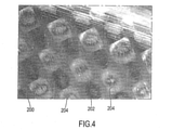
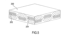
図4は、熱硬化性樹脂内に包埋されたカーボン繊維を含む複合材料の、圧縮成型後の表面を示す拡大画像である。図5は、図4の拡大画像の全体概略図である。 FIG. 4 is an enlarged image showing the surface of a composite material containing carbon fibers embedded in a thermosetting resin after compression molding. FIG. 5 is an overall schematic view of the enlarged image of FIG.
ほぼ表面にある、前記材料の最外層は、繊維202、204を完全に覆う樹脂200単体の膜からなる。その表面は、触覚でも実質的に滑らかである。樹脂200をとおして見た場合、縦繊維202の、それが横繊維の上を通る暗色の部位(繊維製品の分野では「浮部」とも称される部位)と、横繊維204の、縦繊維202がその下を通る明色の部位(繊維製品の分野では「沈部」とも称される部位)のみが、肉眼でも視認できる。
The outermost layer of the material, which is substantially on the surface, consists of a film of
当業者であれば、横繊維204の前記部位が縦繊維202の前記部位よりも明るく見える理由は、照明の反射作用(表面に対して垂直でない反射作用)に加え、横繊維が縦繊維と比べて僅かに張りが弱いために樹脂200の表面からの深さが平均的に僅かに浅くなっているためであることを理解するであろう。
For those skilled in the art, the reason why the part of the
この具体的な例では、それは、繊維含有量(繊維の目付:FAW)が200g/m2の、3kカーボン繊維からの平織布帛である。織りピッチはいずれの方向も約2mmであり、横繊維と縦繊維との段差(difference in level)は約40ミクロンである。 In this specific example, it is a plain weave fabric from 3k carbon fiber with a fiber content (fiber basis weight: FAW) of 200 g / m 2 . The weaving pitch is about 2 mm in each direction, and the difference in level between the weft fibers and the warp fibers is about 40 microns.
このように表面が実質的に滑らかなことから、成形プロセスのみで得られた複合材料からなる車輪用部品は、制動性能、特に、雨天時制動性能は、満足がいくものとはならない。 Since the surface is substantially smooth as described above, the wheel parts made of a composite material obtained only by the molding process are not satisfactory in braking performance, particularly braking performance in rainy weather.
本発明では、少なくとも1つの制動エリア42、44、54の少なくとも1つの領域に、後述する成形後表面加工を施し、これによってその制動性能、特に、雨天時制動性能を向上させる。力説すべき点は、2つのブレーキトラック又はブレーキエリア42、44、54がある場合に、それら2つの一方のみを、1または2以上の被加工領域を有するものとしてもよいことである。
In the present invention, at least one region of at least one
また、両方の制動エリア42、44、54が加工される場合には、それらの加工は必ずしも同一である必要はない。事実、後で明らかになるように、異なる加工とする方がある種の観点からは好適である。
Further, when both braking
前記成形後加工は、第1の加工と第2の加工とを含む。 The post-molding process includes a first process and a second process.
前記第1の成形後加工では、構造繊維202、204を除去せず高分子材料又は樹脂200のみが除去される。この第1の加工では、構造繊維202、204が意図的に除去されたりすり減らされたり切断されたりしない。ただ実際には、もはや高分子材料内に十分に埋め込まれなくなかった一部の繊維片が表面から離れる可能性はある。
In the first post-molding process, only the polymer material or the
前記第1の加工は、加工されることが意図される領域全体、つまり、少なくとも1つの制動エリア42、44、54における少なくとも1つの領域の表面全体に及ぶ。例えば、前記第1の加工は、リム14における環状のブレーキトラック42の全体または該ブレーキトラック42の少なくとも1つのセクタ(部位)に及ぶものとされ得る。
The first process covers the entire area intended to be machined, i.e., the entire surface of at least one area in at least one
除去度が樹脂200単体の表面膜を超えて増えるにつれて、樹脂のこのような除去は、氷河の削り取りの如く作用して、樹脂を「浸食」し、繊維の部位が徐々に露出して表面に近づく。
As the degree of removal increases beyond the surface film of the
前記第1の成形後加工により、前記構造繊維が少なくとも一部前記高分子材料から露出する。 By the first post-molding process, at least a part of the structural fiber is exposed from the polymer material.
よって、被加工領域は、表面層において、該被加工領域に隣接する領域等の未加工領域よりも少量の高分子材料および該未加工領域と実質的に等量の構造繊維を有する。これらの「量」とは、単位面積当たりの量のことを意味する。 Therefore, the processed region has a smaller amount of polymer material and substantially the same amount of structural fibers as the unprocessed region in the surface layer than the unprocessed region such as the region adjacent to the processed region. These "quantities" mean quantities per unit area.
前記第1の加工により、僅かに窪んだ部分と僅かに盛り上がった部分とが形成される。 By the first processing, a slightly recessed portion and a slightly raised portion are formed.
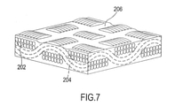
図6は、図4において中程度の樹脂除去を受けた材料の表面、つまり、平均的な量の残留樹脂が存在している表面を示す拡大画像である。図7は、図6の拡大画像の全体概略図である。 FIG. 6 is an enlarged image showing the surface of the material that has undergone moderate resin removal in FIG. 4, i.e., the surface in which an average amount of residual resin is present. FIG. 7 is an overall schematic view of the enlarged image of FIG.
明らかに、樹脂は、縦糸202(「浮部」)を構成する繊維の高さまで実質的に除去されており、該縦糸202は、図6では暗色に見える小さな盛り上がりを構成している。横糸を構成する繊維204は、横繊維の上になる中央部において露出しており、ここで表面に向かって突出して、図6では明色の、簡単に視認できるより顕著な盛り上がりを構成している。
Obviously, the resin has been substantially removed to the height of the fibers constituting the warp 202 (“floating portion”), which constitutes a small ridge that appears dark in FIG. The
繊維202、204が露出している箇所には、樹脂膜200は残っていない。
The
横繊維204が縦繊維202の下に入る箇所(横繊維204が曲率を変え、表面に対し凹形となる変曲点近傍の箇所)では、残存樹脂200は、横繊維204を覆い隠すのにいまだ十分な厚さを持っている。実際に図6では、樹脂200の帯状領域206が、左下から右上にかけて斜めに延びていることがわかる。
At the place where the
触覚に対しても、表面はもはや滑らかではなく、横繊維204及び縦繊維202の盛り上がりと、樹脂200の帯状部分206での「溝」を感じ取ることができる。
The surface is no longer smooth to the touch, and the swelling of the
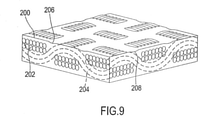
図8は、図4において樹脂を軽く除去した材料の表面、つまり、大量の残留樹脂が存在している表面を示す拡大画像である。図9は、図8の拡大画像の全体概略図である。樹脂200は、構造繊維が突出する部位、すなわち、縦繊維202が横繊維の上を通る部位(「浮部」)の中央領域、および横繊維204が縦繊維の上を通る部位(「沈部」)の中央領域のみで除去されている。
FIG. 8 is an enlarged image showing the surface of the material from which the resin has been lightly removed in FIG. 4, that is, the surface in which a large amount of residual resin is present. FIG. 9 is an overall schematic view of the enlarged image of FIG. The
横繊維204の盛り上がり(明色部)は、図6及び図7の状態ほど顕著ではなく、図面左下から右上にかけて斜めに延びる樹脂200の帯状部分206の幅がより広くなっている。
The swelling (bright color portion) of the
縦繊維202(暗い色)も、横繊維より上に位置する部位(「浮部」)の中央領域でのみ突出しており、小さな盛り上がりを形成している。 The warp fibers 202 (dark color) also project only in the central region of the portion (“floating portion”) located above the weft fibers, forming a small ridge.
縦繊維202が横繊維204の下に入る箇所(横繊維202が曲率を変え、表面に対し凹形となる変曲点近傍の箇所)では、樹脂200は、横繊維202を覆い隠すのにいまだ十分な厚さを持っている。そのため、同図左上から右下にかけて斜めに延びる樹脂200の第2の帯状部分208が一連に形成されている。
At the place where the
横繊維204及び縦繊維202の盛り上がりと樹脂200の帯状部分206、208での「溝」は、触覚でも感じ取ることができる。その表面は、成形直後の当初の状態のように滑らかではないものの、図6及び図7よりは滑らかである。
The swelling of the
図10は、図4において極めて高度の樹脂除去を受けた材料の表面、つまり、極めて少量の残留樹脂しか存在しない表面を示す拡大画像である。図11は、図10の拡大画像の全体概略図である。樹脂はほぼ完全に除去されており、繊維布帛を完全に視認できる。具体的には、最外側にあるのがどちらであるかにかかわらず、縦繊維202および横繊維204の全部位を視認できる。その表面は、手触りも粗い。
FIG. 10 is an enlarged image showing the surface of the material that has undergone extremely high degree of resin removal in FIG. 4, that is, the surface in which only a very small amount of residual resin is present. FIG. 11 is an overall schematic view of the enlarged image of FIG. The resin has been almost completely removed and the fiber fabric is completely visible. Specifically, all parts of the
当業者であれば、名義上同一の出発材料および名義上同一の成形プロセスを用いた場合でも、成形後の2つの車輪用部品は、構造繊維の外観および表面における樹脂量に実質的な差を生じ得ることを理解するであろう。前記第1の成形後加工にも、名義上同一のプロセスを用いたとしても、構造繊維の外観および残留樹脂の量に実質的な差を生じ得る。よって、上記で説明した各図は、単に例示に過ぎないと見るべきである。 For those skilled in the art, even when using the same starting material and the same molding process in the name, the two wheel parts after molding have a substantial difference in the appearance and the amount of resin on the surface of the structural fiber. You will understand that it can happen. Even if the same process is used in the first post-molding process, there may be a substantial difference in the appearance of the structural fibers and the amount of residual resin. Therefore, each figure described above should be viewed as merely an example.
力説すべきは、前記第1の成形後処理を受けた領域は、ブレーキのパッド等の制動体により摩耗された表面とは異なり、依然一定の表面均一性を有することである。後者は制動体の表面および/または、制動体が制動エリアへ運んだ土、石等により形成される、不均一な溝で特徴づけられる。 It should be emphasized that the region subjected to the first post-molding treatment still has a certain surface uniformity, unlike the surface worn by the braking body such as a brake pad. The latter is characterized by non-uniform grooves formed by the surface of the braking body and / or the soil, stones, etc. carried by the braking body to the braking area.
当業者であれば、異なる織り方の場合または不織布の場合には、外観および手触りが図4~図11を参照しながら明示したものと大幅に異なるものの、いずれにしろ樹脂の除去度が増えるにつれ、露出した繊維の割合が増え、表面粗さが増すことを理解するであろう。 Those skilled in the art will find that in the case of different weaves or non-woven fabrics, the appearance and texture will be significantly different from those specified with reference to FIGS. 4 to 11, but in any case, as the degree of resin removal increases. You will understand that the proportion of exposed fibers increases and the surface roughness increases.
また、ベースの複合材料を変更すること、特に繊維束当たりのフィラメント数を変更することにより、表面粗さを減少させる(増加させる)ことが可能である。 It is also possible to reduce (increase) the surface roughness by changing the composite material of the base, especially by changing the number of filaments per fiber bundle.
単に、さらに具体的な一例であるが、軽量の1k繊維を用いて製作されたカーボン布帛を含む(例えば、繊維含有量が100g/m2の)複合材料を使用してもよい。この場合、3k繊維を用いて製作された布帛に比べ、織りピッチおよび縦繊維と横繊維との段差が小さい(織りピッチがおよそ1.3mmで、段差がおよそ20ミクロンである)。さらに他の例として、ガラス繊維を含む複合材料(例えば、繊維含有量が50g/m2のもの)を使用してもよい。この場合の複合材料は、織りピッチおよび縦繊維と横繊維との段差はなお小さくなる(織りピッチがおよそ0.4mmで、段差がおよそ10ミクロンである)。 Simply, as a more specific example, composite materials containing carbon fabrics made with lightweight 1k fibers (eg, fiber content of 100 g / m 2 ) may be used. In this case, the weaving pitch and the step between the warp fibers and the weft fibers are smaller than those of the fabric manufactured using the 3k fibers (the weaving pitch is about 1.3 mm and the step is about 20 microns). As yet another example, a composite material containing glass fibers (for example, one having a fiber content of 50 g / m 2 ) may be used. In the composite material in this case, the weaving pitch and the step between the warp fibers and the weft fibers are still small (the weaving pitch is about 0.4 mm and the step is about 10 microns).
好適なことに、「マット」の形態の複合材料を出発材料とする自転車用部品を成形する場合、少なくとも制動エリア42、44、54および/またはその一部で、本発明にかかる成形後加工を受ける領域においては、車両用部品の表層部には比較的軽い複合材料を使用し、非表面層については比較的重い複合材料を使用してもよい。このようにして、車輪用部品の強度を減らすことなく所望の表面粗さを得ることができる。
Preferably, when molding a bicycle part starting from a composite material in the form of a "mat", at least in the
よって車輪用部品における複合材料の表面層における繊維含有量(繊維の目付:FAW)を、少なくとも前記制動エリアにおいて、非表面層における繊維含有量よりも少ないものとしてもよい。 Therefore, the fiber content (fiber basis weight: FAW) in the surface layer of the composite material in the wheel component may be lower than the fiber content in the non-surface layer at least in the braking area.
好ましくは、前記車輪用部品における前記複合材料は、少なくとも前記制動エリアにおいて、表面層の繊維含有量が100g/m2以下であってもよい。 Preferably, the composite material in the wheel component may have a fiber content of the surface layer of 100 g / m 2 or less, at least in the braking area.
出願人は、樹脂の除去度について様々な例的条件で前記第1の成形後加工に付された車輪リムについて、晴天時制動性能及び雨天時制動性能を試験し、以下のことを見出した。なお、数十回の制動動作の実行からなるサイクルを2回行い、平均制動時間を測定した。1つのサイクルと次のサイクルとの間で、約1000キロメートルの使用状態がシミュレートされた。 The applicant tested the braking performance in fine weather and the braking performance in rainy weather on the wheel rims subjected to the first post-molding process under various exemplary conditions for the degree of resin removal, and found the following. The average braking time was measured by performing two cycles consisting of several tens of executions of braking operation. Between one cycle and the next, about 1000 kilometers of usage was simulated.
樹脂の除去度が増えるにつれて、ブレーキパッドの摩耗は若干増加する。これは、表面粗さ(したがって、摩擦)が増すことから想定の範囲内である。ただし、強調すべきは、制動体のある程度の摩耗が、該制動体の表面状態を再生でき、摩擦又はグリップを安定化できるので好適という点である。 As the degree of resin removal increases, the wear of the brake pads increases slightly. This is within the expected range due to the increased surface roughness (and therefore friction). However, it should be emphasized that a certain amount of wear of the braking body is preferable because the surface condition of the braking body can be regenerated and friction or grip can be stabilized.
制動時間の観点からみた晴天時制動性能は、若干の悪化はあるにしても、樹脂の除去度が増えても実質的に不変のままである。これは、表面粗さが増すことにより、制動体との実際の接触面積および凝着による摩擦が減ることから予想されるとおりである。 The braking performance in fine weather from the viewpoint of braking time remains substantially unchanged even if the degree of resin removal increases, although there is some deterioration. This is as expected from the fact that the increased surface roughness reduces the actual contact area with the braking body and the friction due to adhesion.
一方、制動時間の観点からみた雨天時制動性能は、樹脂の除去度が増えるにつれて大幅に向上する。重度の樹脂除去を受けたリムの制動時間は、軽度の樹脂除去を受けたリムの制動時間の約1/3まで短縮する。何らかの理論に縛られることを意図するものではないが、出願人は、これは制動体と制動エリアとの間に形成されがちな水の膜が、表面の粗さにより壊されることによるものと考慮している。 On the other hand, the braking performance in rainy weather from the viewpoint of braking time is significantly improved as the degree of resin removal increases. The braking time of a rim that has undergone heavy resin removal is reduced to about one-third of the braking time of a rim that has undergone mild resin removal. Although not intended to be bound by any theory, the Applicant considers this to be due to the water film that tends to form between the braking body and the braking area being broken by the surface roughness. is doing.
出願人はまた、雨天時制動性能は、いかなる場合にも、高分子材料が完全に除去される前に、樹脂の表面を超えて突出する繊維に対してのみ、制動体が自身の剛性によって接触する一方、該制動体が樹脂ともはや接触しなくなる時点で(しかも、樹脂をさらに除去しても摩擦は増えないことから)最大限度まで向上すると考慮する。 The applicant also said that in any case, the braking performance in rainy weather is such that the braking body contacts by its own rigidity only to the fibers protruding beyond the surface of the resin before the polymer material is completely removed. On the other hand, when the braking body no longer comes into contact with the resin (and the friction does not increase even if the resin is further removed), it is considered to be improved to the maximum.
一方、樹脂の除去度が増えるにつれ、制動にはある程度の音量の騒音を伴うようになり、音量は次第に増加する。何らかの理論に縛られることを意図するものではないが、出願人は、これが表面粗さの増加に起因すると考えている。したがって、騒音を低く抑えるには、一束当たりのフィラメント数が少ない繊維を含む複合材料を使用するのが好ましい。 On the other hand, as the degree of resin removal increases, braking is accompanied by a certain amount of noise, and the volume gradually increases. Although not intended to be bound by any theory, Applicants attribute this to an increase in surface roughness. Therefore, in order to keep noise low, it is preferable to use a composite material containing fibers having a small number of filaments per bundle.
また、出願人の見たところ、高分子材料の樹脂は、構造繊維同士を集合として維持する重要な役割を果たしており、そのため複合材料に安定性を付与している。 Further, from the applicant's point of view, the resin of the polymer material plays an important role of maintaining the structural fibers as an aggregate, and thus imparts stability to the composite material.
また、高分子材料の樹脂は、水分および空気中物質からの絶縁を行うという重要な役割を果たすものと考慮される。 In addition, the resin of the polymer material is considered to play an important role of insulating from moisture and substances in the air.
また、出願人は、被加工領域の表面全体からの高分子材料を除去する加工は、特に、このような加工が後述する技術を用いて実行されるものである場合、看過し得ないほどの加工時間が必要となること、さらには、樹脂の除去度が増えるにつれてこの加工時間が長くなることを見出した。 In addition, the applicant cannot overlook the processing for removing the polymer material from the entire surface of the work area, especially when such processing is performed by using the technique described later. It has been found that processing time is required, and that the processing time increases as the degree of resin removal increases.
そのため、出願人は、総合的に見て、過度に大きな樹脂の除去度は好ましくないものと考えている。 Therefore, the applicant considers that the degree of removal of an excessively large resin is not preferable as a whole.
出願人は、第1の成形後加工に次いで、後述の本発明にかかる第2の成形後加工が行われた場合には、中程度の樹脂除去とする加工で十分であることを見出した。 The applicant has found that when the first post-molding process is followed by the second post-molding process according to the present invention described below, a process with moderate resin removal is sufficient.
前記第1の成形後加工は、60%以上の高分子材料を除去するように実施することが望ましい。 It is desirable that the first post-molding process be carried out so as to remove 60% or more of the polymer material.
これにより、被加工層における残留高分子材料の量は、表面層において、加工前のその部分に存在する高分子材料の量(よって、隣接領域に存在する高分子材料の量)の40%以下となる。 As a result, the amount of residual polymer material in the work layer is 40% or less of the amount of polymer material present in that portion of the surface layer before processing (hence, the amount of polymer material present in the adjacent region). It becomes.
両方の制動エリア42、44、54が加工対象である場合、例えば全体的な騒音を抑えるため、一方のエリアと他方のエリアで高分子材料の除去度が異なってもよい。
When both
前記第2の成形後加工では、前記第1の成形後加工で少なくとも一部露出させられた構造繊維202、204、および場合によっては高分子材料又は樹脂200の除去が実行される。この第2の加工では、構造繊維202、204が意図的に切断される。
In the second post-molding process, removal of at least partially exposed
この点に関して、出願人は、構造繊維の平均厚さが薄いので、表面加工により切り刻まれた単繊維は樹脂から完全に解き放たれるか切断されるかのいずれかのみであり、その一部のみが取り除かれて楕円状の部位(繊維をその曲面部で切り取ったときに理論的にみて形成可能である楕円状の部位)を形成するようなことは可能でないことを見出した。 In this regard, the applicant has stated that because the average thickness of the structural fibers is thin, the single fibers chopped by the surface treatment are either completely released from the resin or cut, and only a part of them. It has been found that it is not possible to remove and form an elliptical part (an elliptical part that can theoretically be formed when the fiber is cut off at its curved surface).
前記第1の加工とは異なり、前記第2の成形後加工は、被加工領域の表面全体に及ばない。むしろ、この第2の加工は、少なくとも1つの溝に従って複合材料の除去を行うものである。 Unlike the first processing, the second post-molding processing does not cover the entire surface of the work area. Rather, this second process is to remove the composite material according to at least one groove.
本明細書および添付の特許請求の範囲において「溝」とは、所定の長さで延び、有限の深さ及び幅を持つ凹部を指すものとする。 As used herein and in the appended claims, "groove" is meant to refer to a recess extending in a predetermined length and having a finite depth and width.
好ましくは、複合材料の除去は、溝のパターンに従って、つまり、被加工領域の表面内における複数の分離した溝に従って実行される。 Preferably, the removal of the composite material is carried out according to the groove pattern, i.e., according to a plurality of separated grooves within the surface of the work area.
「分離した溝」とは、2つの隣合う溝間の距離の最小値が、1つの溝の幅よりも一桁以上大きいものを指すものとする。 The "separated groove" means that the minimum value of the distance between two adjacent grooves is one digit or more larger than the width of one groove.
制動エリア42、44、54が環状であるか又は部分円環を構成するものである場合、前記複数の分離した溝は、制動エリア42、44、54に対し径方向に延びる直線状の溝を含むことが好ましい。
When the
径方向に延びる溝に代えて、異なる溝パターン、特に、減速・制動時に遠心力により制動エリア42、44、54から水の排除を促すものとして研究済みの溝パターンが設けられてもよい。
Instead of the radially extending groove, a different groove pattern, in particular a groove pattern studied to promote the removal of water from the
例えば、前記溝のパターンは、径方向以外の方向に延びる直線状の溝、および/または曲線状の溝、および/または同心状の溝、および/または波状の溝を含むものであってもよい。 For example, the groove pattern may include linear grooves and / or curved grooves and / or concentric grooves and / or wavy grooves that extend in directions other than the radial direction. ..
前記複数の分離した溝は、一定の回転対称性を有するものであってもよく、有さないものであってもよい。「回転対称性」とは、回転後も溝の全体的な配置構成が変わらない、軸回りの回転角が少なくとも1つ存在することを指すものとする。環状の制動エリア42、44、54の場合、これらの溝は、周方向に沿って一様に分布したものであっても周方向に沿って周期的に分布したものであっても周方向に沿って非周期的に分布したものであってもよい。
The plurality of separated grooves may or may not have a certain rotational symmetry. "Rotational symmetry" means that there is at least one rotation angle around the axis in which the overall arrangement of the grooves does not change even after rotation. In the case of the
あるいは、好適には、前記第2の加工において、本願の最先出願日の時点で非公開の欧州特許出願第15164190.9号(対応米国特許出願第14/692,268号)において金属製リムとの関連で記載されているものと同様の、らせん状の溝を形成してもよい。 Alternatively, preferably, in the second process, the metal rim in European Patent Application No. 15164190.9 (corresponding US Patent Application No. 14 / 692,268), which was not published as of the earliest filing date of the present application. Spiral grooves may be formed similar to those described in the context of.
本明細書の以降の説明および添付の特許請求の範囲において「らせん状の溝」とは、らせん状の経路に沿って途切れなく延びる切れ込み(この場合は、「単一の連続溝」という表現を用いる)と、溝のない表面部位によって途切れる、らせん状の経路に沿って交互に続く複数の溝(又は複数の部分溝)との両方を包括的に示すものとする。 As used herein and in the appended claims, the term "spiral groove" refers to a notch that extends seamlessly along a spiral path (in this case, the expression "single continuous groove". Used) and multiple grooves (or multiple partial grooves) that alternate along a spiral path, interrupted by a grooveless surface site, shall be comprehensively indicated.
図12は、前記第2の成形後加工により形成された溝のパターンの一例を示す概略図である。 FIG. 12 is a schematic view showing an example of a groove pattern formed by the second post-molding process.
この溝のパターンは、環状の形状を有するか又は部分円環を構成する制動エリア42、44、54において径方向に延びる、複数の溝210を含む(なお、いずれの場合としても、図示されているのは一部分であり、図示を分かり易くするために曲率は誇張されており、図面は実際のスケールを示すものではない)。
The groove pattern includes a plurality of
各溝210は、幅L1、長さL2および深さPを有する。
Each
隣合う溝210は、平均距離Dで互いに隔てられている。該溝の幅を無視した、隣合う溝間の、離間角度は、符号Aで表される。
制動エリア42、44、54の、径方向の高さは、符号Hで表される。
The radial heights of the
溝210の幅L1は、長さL2よりも少なくとも一桁以上小さい。
The width L1 of the
好ましくは、深さPは、幅L1よりも小さく、より好ましくは、幅L1よりも少なくとも一桁以上小さい。 Preferably, the depth P is smaller than the width L1 and more preferably at least an order of magnitude smaller than the width L1.
好ましくは、長さL2は、図示されるように制動エリア42、44、54の径方向高さHと同程度であり、より好ましくは同一である。
Preferably, the length L2 is about the same as, more preferably, the same as the radial height H of the
いうまでもなく、溝210間の距離Dおよび離間角度(角度ピッチ)Aは、溝210の数の逆関数となる。
Needless to say, the distance D and the separation angle (angle pitch) A between the
溝の総数は、符号Nで表される。 The total number of grooves is represented by the reference numeral N.
溝210の幅を無視すれば、A=360°/Nの関係が成り立つ。
If the width of the
これらの量についての数値は、切断された構造繊維が制動エリア42、44、54の表面の9%以下、より好ましくは約5%を占めるように選択されることが好ましい。強調すべきは、溝210が摩耗インジケータではない点である。実際、溝又は凹部を摩耗インジケータとして使用することは知られているが、通常、これは環状の制動エリアに沿った単一の角度方向位置に限定される。しかも、そのような場合には典型的に、溝又は摩耗インジケータ凹所の底と周囲の制動エリアの表面との間に色コントラストを作り出すように材料が使用されるのに対し、溝210の場合はそうではない。
Numerical values for these amounts are preferably selected such that the cut structural fibers occupy 9% or less, more preferably about 5% of the surface of the
溝210の直断面は、図示されるように長方形であってもよいし、丸みを帯びた形状であってもよいし、三角形であってもよいし、あるいは、他の形状であってもよい。
The straight cross section of the
両方の制動エリア42、44、54が加工対象である場合、溝パターンは、例えば騒音を抑えるために、制動エリアごとに異なってもよい。
When both
図13は、前記第2の成形後加工により形成された溝のパターンの他の例を示す概略図である。 FIG. 13 is a schematic view showing another example of the groove pattern formed by the second post-molding process.
この溝のパターンは、周方向成分と径方向成分とを有する、複数の曲線状の溝212を含む。周方向と径方向の二つの成分は同程度なので、溝は径方向に対して約45°をなして延在している。この図でも、図示を分かり易くするために制動エリア42、44、54の曲率を誇張されており、図面は実際のスケールを示すものではない。
This groove pattern includes a plurality of
図14は、熱硬化性樹脂のマトリクス内のカーボン繊維を含む複合材料からなる自転車用リム14の一部を示す拡大画像であり、制動エリア42、44および隣接領域56が示されている。制動エリア42、44は、中程度の量の残留樹脂が表面に存在しており(つまり、第1の成形後加工において中程度の樹脂除去を受けており)、図12に従って、距離D、離間角度(角度ピッチ)A、および幅L1が所定値を有する溝パターンを備えている。
FIG. 14 is an enlarged image showing a portion of a
図15は、図14と類似する画像であり、図12に従った溝のパターンを有しているが、図14よりも距離D及び離間角度Aが小さく且つ図14よりも幅L1が小さい。 FIG. 15 is an image similar to FIG. 14, and has a groove pattern according to FIG. 12, but the distance D and the separation angle A are smaller than those of FIG. 14, and the width L1 is smaller than that of FIG.
すなわち、図14では比較的、少ない数の幅広な溝210が存在するのに対し、図15では比較的、多数の幅狭な溝210が存在する。
That is, in FIG. 14, there are a relatively small number of
出願人が、上述した第2の加工も受けた各種車輪リムについて、晴天時制動性能及び雨天時制動性能を試験した結果、下記のことが判明した。ここにおいても、数十回の制動動作の実行からなるサイクルを2回行い、平均制動時間を測定した。1つのサイクルと次のサイクルとの間の時点で、約1000キロメートルの使用状態がシミュレートされた。 As a result of testing the braking performance in fine weather and the braking performance in rainy weather for various wheel rims that have undergone the second processing described above, the applicant has found the following. Here, too, a cycle consisting of several tens of executions of braking operation was performed twice, and the average braking time was measured. At the time between one cycle and the next, about 1000 kilometers of usage was simulated.
ブレーキパッドの摩耗は、前記第1の加工のみを受け、同程度の樹脂が除去されたリムと比べて、溝の存在によって実質的には変化はない。これは、溝が平均表面粗さを実質上変化させないことから、想定の範囲である。 Brake pad wear is substantially unchanged by the presence of grooves as compared to rims that have undergone only the first process and have the same degree of resin removed. This is within the expected range because the grooves do not substantially change the average surface roughness.
晴天時制動性能についても、無視しうる程度の平均的悪化はあるが、前記第1の加工のみを受け、同程度の樹脂が除去されたリムと比べても、実質的に変化はない。この挙動は、平均表面粗さが実質的に変化しないことを考慮すれば、想定の範囲内である。 Although there is a negligible average deterioration in braking performance in fine weather, there is virtually no change compared to a rim that has undergone only the first processing and has the same degree of resin removed. This behavior is within the expected range, considering that the average surface roughness does not change substantially.
好ましいことに、前記第1の成形後加工時の高分子材料除去の程度を中程度または極めて軽度に留めたとしても、前記第2の成形後加工により、十分に許容可能な雨天時制動時間が得られることが判明した。 Preferably, the second post-molding process provides a sufficiently acceptable rain braking time, even if the degree of polymer material removal during the first post-molding process is moderate or very mild. It turned out to be obtained.
また、切断される繊維の合計割合を一定に設定したうえで、溝210のパターンを多数の幅狭な溝(例えば、図15等のような溝)を含むものとした場合、溝210のパターンを少数の幅広な溝(例えば、図14等のような溝)を含むものとした場合よりも、全体的により良好な性能が得られることが判明した。
Further, when the total ratio of the fibers to be cut is set to be constant and the pattern of the
さらに、好適なことに、溝210は、制動時の騒音を実際に除去しないまでも実質的に減少させる。
Further, preferably, the
騒音の観点からみると、周方向成分が径方向成分よりも大きいか又は同程度の方向に延在する溝(例えば、図13の溝212等のような溝)が、径方向成分が周方向成分よりも大きい方向に延在する溝よりも好ましいことがわかるであろう。
From the viewpoint of noise, a groove having a circumferential component larger than or extending in the same direction as the radial component (for example, a groove such as the
まとめると、前記第2の加工工程および溝210を設けることにより、前記第1の加工工程における樹脂除去の程度を少なく抑えたとしても、かなりの性能を得ることが可能になる。結果として、表面における大量の残留樹脂の存在により、より安定的で絶縁性のよい、効果的な制動エリアを得ることができる。
In summary, by providing the second processing step and the
比較のために、同じ複合材料を用いて作製され、成形後「ダイヤモンド研削」加工(つまり、ダイヤモンドと同程度の硬度の工具を用いての表面層の除去)に付された車輪リムについて、晴天時制動性能及び雨天時制動性能を試験した。このような加工では、本発明にかかる加工とは異なり、被加工部分全体において構造繊維の除去と高分子材料の除去とが同時に行われ、被加工面が実質的に平坦に且つ滑らかなままとなる。構造繊維が露出する本発明の場合とは異なり、三次元の(立体的な)表面は形成されない。 For comparison, fine weather for wheel rims made using the same composite and subjected to post-molding "diamond grinding" processing (ie, removal of the surface layer using a tool as hard as diamond). The hourly braking performance and the rainy weather braking performance were tested. In such processing, unlike the processing according to the present invention, the removal of structural fibers and the removal of the polymer material are performed simultaneously in the entire processed portion, so that the surface to be processed remains substantially flat and smooth. Become. Unlike the case of the present invention where the structural fibers are exposed, a three-dimensional (three-dimensional) surface is not formed.
この比較から、好適なことに、本発明にかかる加工が雨天時制動性能を向上させることが判明した。 From this comparison, it was found that, preferably, the processing according to the present invention improves the braking performance in rainy weather.
その上、本発明に従って作製されたリムの雨天時制動性能は、ダイヤモンド研削を受けたリムと比べて劣化が大幅に少ない。この点に関して、出願人は、約1000キロメートルのシミュレートされた使用後には、ダイヤモンド研削を受けたリムの雨天時制動時間は2倍になり得ることを見出した。 Moreover, the rain braking performance of rims made according to the present invention is significantly less degraded than rims that have undergone diamond grinding. In this regard, Applicants have found that after about 1000 kilometers of simulated use, the rain braking time of a diamond-ground rim can be doubled.
晴天時には、本発明に従って作製されたリムとダイヤモンド研削を受けたリムの制動性能とは同程度である。 In fine weather, the braking performance of a rim made according to the present invention and a rim subjected to diamond grinding are comparable.
強調すべきは、2種類の前記加工が実行される順番を逆にすることも可能な点である。この場合、前記溝での経路が二重になるので、総加工時間が長くなると共に使用パワーの増加にも繋がるものの、前記第2の加工で形成された溝の整然性が低くなることで、結果的に前記制動体の摩耗が少なくなる。また、2種類の加工処理を同時に実行することも可能である。 It should be emphasized that it is possible to reverse the order in which the two types of processing are performed. In this case, since the path in the groove is doubled, the total processing time becomes long and the power used increases, but the ordering of the groove formed in the second processing becomes low. As a result, the wear of the braking body is reduced. It is also possible to execute two types of processing at the same time.
好ましくは、前記成形後加工の後に、前記制動エリアから、アブレーション時に生成された構造繊維及び高分子材料の残渣を除去する清浄化工程が設けられる。このような清浄化工程は、アセトンを染み込ませた布を単純に複数回動かすことによって行われるものであってもよい。 Preferably, after the post-molding process, a cleaning step is provided from the braking area to remove residues of structural fibers and polymeric materials produced during ablation. Such a cleaning step may be performed by simply moving the cloth impregnated with acetone a plurality of times.
好ましくは、前記第1の成形後加工での高分子材料の選択的除去および/または前記第2の成形後加工での溝の形成は、熱分解、つまり、熱的手段を用いた分解により行われる。 Preferably, the selective removal of the polymeric material in the first post-molding process and / or the formation of grooves in the second post-molding process is carried out by thermal decomposition, i.e., decomposition using thermal means. Will be.
原則として、前記第1の成形後加工における高分子材料の選択的除去に、化学的手段を使用することも可能である。 In principle, it is also possible to use chemical means for the selective removal of the polymeric material in the first post-molding process.
好ましくは、前記熱分解は、高エネルギービームを介して行われる。 Preferably, the thermal decomposition is carried out via a high energy beam.
好ましくは、前記熱分解は、パルス照射の高エネルギービームを用いて行われる。 Preferably, the thermal decomposition is carried out using a high energy beam of pulse irradiation.
好ましくは、前記熱分解は、レーザビームを用いて行われる。 Preferably, the thermal decomposition is carried out using a laser beam.
より好ましくは、前記熱分解は、近赤外(NIR)領域のレーザビーム、例えば、1064ナノメートルの波長を有するレーザビームを用いて行われる。しかしながら、緑色領域、紫外領域、非近赤外領域等のレーザビームを使用することも可能である。紫外領域のレーザを使用することには、高分子材料の黄変を全く引き起こさないという利点があるが、通常、NIRレーザと比べて装置コストおよび加工時間は増加する(加工時間が二倍にもなる可能性がある)。 More preferably, the thermal decomposition is carried out using a laser beam in the near infrared (NIR) region, for example, a laser beam having a wavelength of 1064 nanometers. However, it is also possible to use a laser beam in a green region, an ultraviolet region, a non-near infrared region, or the like. The use of lasers in the UV region has the advantage of not causing any yellowing of the polymer material, but usually increases equipment costs and processing time compared to NIR lasers (double the processing time). Can be).
高分子材料は構造繊維と比べて熱分解に対する耐性が低いので、高エネルギービームによる入熱は、前記第1の成形後加工では高分子材料のアブレーション又は分解のみが生じるように比較的小さく調整し、前記第2の成形後加工では構造繊維のアブレーション又は分解も生じるように比較的高く調節すればよい。 Since the polymer material has a lower resistance to thermal decomposition than the structural fiber, the heat input by the high energy beam is adjusted to be relatively small so that only ablation or decomposition of the polymer material occurs in the first post-molding process. In the second post-molding process, the structural fibers may be adjusted to be relatively high so as to cause ablation or decomposition of the structural fibers.
前記第1の加工時に高分子材料の除去度調整のための入熱の調節、および前記第1と前記第2の加工との間の移行時における入熱の調節するため、パルスの出力および/またはパルスの焦点長さおよび/またはパルス照射周波数および/または高エネルギービームの走査速度を調節してもよい。 To adjust the heat input to adjust the degree of removal of the polymer material during the first processing, and to adjust the heat input during the transition between the first and second processing, the pulse output and / Alternatively, the focal length of the pulse and / or the pulse irradiation frequency and / or the scanning speed of the high energy beam may be adjusted.
両方の加工に同じ光源を使用することは、装置のコスト面からみて、セットアップすべき場所が一つで済むことからみて、また必要な人員からみて利点が大きい。実際、車輪用部品を1つの加工ステーションから別の加工ステーションへと移動させる必要がなく、前記第1と前記第2の加工との間で光源の動作パラメータを変更すれば十分である。 Using the same light source for both processes is a great advantage in terms of equipment cost, because it requires only one place to set up, and in terms of the required personnel. In fact, it is not necessary to move the wheel parts from one machining station to another, it is sufficient to change the operating parameters of the light source between the first and second machining.
以下は、前記第1の成形後加工の実行に適したレーザビームの構成条件の一例である:
波長:1064nm
定格出力:20W
実出力:100%
焦点長さ:254mm
パルス照射周波数:25kHz
走査速度:1500~4000mm/秒
隣接する走査線間の間隔:0.05~0.075mm
The following is an example of a laser beam configuration condition suitable for performing the first post-molding process:
Wavelength: 1064 nm
Rated output: 20W
Actual output: 100%
Focus length: 254 mm
Pulse irradiation frequency: 25 kHz
Scanning speed: 1500-4000 mm / sec Spacing between adjacent scanning lines: 0.05-0.075 mm
この構成条件によれば、黄色/茶色への樹脂の変色を許容可能なレベルに抑えることができる。 According to this configuration condition, the discoloration of the resin to yellow / brown can be suppressed to an acceptable level.
上述のように、樹脂の除去度を増やすには、出力を上げるか、かつ/または走査数を増やすか、かつ/または走査線間の間隔を短くすればよい。 As described above, in order to increase the degree of removal of the resin, the output may be increased and / or the number of scans may be increased, and / or the interval between the scan lines may be shortened.
前記第2の成形後加工を実行する際には、例えば、単位面積当たりの供給出力が構造繊維も分解可能なレベルまで増えるように走査速度を少なくとも一桁以上遅く、例えば走査速度:400mm/秒とした上で、上記と同じ構成条件を用いてもよい。 When performing the second post-molding process, for example, the scanning speed is slowed by at least an order of magnitude so that the supply output per unit area increases to a level at which structural fibers can also be decomposed, for example, scanning speed: 400 mm / sec. Then, the same configuration conditions as above may be used.
両方の加工について、被加工領域上でのレーザビームの走査方向は、レーザビームのストロークを最小化し得る方向であることが好ましい。これにより、加工時間を最小化し得るとともに、制動エリアと光源の相対運動をより制御しやすくなる。よって、前記第2の加工(溝の形成)における好適な走査方向は、溝の幅L1方向である。 For both processes, the scanning direction of the laser beam on the area to be machined is preferably a direction that can minimize the stroke of the laser beam. As a result, the machining time can be minimized, and the relative motion between the braking area and the light source can be more easily controlled. Therefore, the preferred scanning direction in the second processing (groove formation) is the groove width L1 direction.
例えば、環状の制動エリアと径方向に延びる溝との好適な構成の場合、レーザビームの走査は、前記第1の加工(ブレーキトラック全体又はその少なくとも1つの領域(例えば、部分円環)の加工)では径方向に行い、前記第2の加工(溝の形成)では周方向に行なってもよい。 For example, in the case of a suitable configuration of an annular braking area and a radially extending groove, scanning the laser beam is the machining of the first machining (the entire brake track or at least one region thereof (eg, a partial annulus)). ) May be performed in the radial direction, and the second processing (groove formation) may be performed in the circumferential direction.
高エネルギービームを用いることにより、2種類の成形後加工を同時に、例えば、構造繊維を除去しなければならない箇所にビームがより長く留まるように走査時間を変化させることによって実行してもよい。 By using a high energy beam, two types of post-molding may be performed simultaneously, eg, by varying the scan time so that the beam stays longer where structural fibers must be removed.
前記第1の成形後加工には、レーザビームに代えて、大気プラズマのジェットを使用してもよい。この場合、加工は極めて均質的であり、レーザの場合には走査線が視認されるのに対し、走査線は視認されない。他方、コストは高くなり、プラズマ源は前記第2の加工への適合性は、あったとしても乏しい。 In the first post-molding process, a jet of atmospheric plasma may be used instead of the laser beam. In this case, the processing is extremely homogeneous, and in the case of a laser, the scanning lines are visible, whereas the scanning lines are not visible. On the other hand, the cost is high and the plasma source is poorly compatible with the second processing, if any.
好ましくは、高エネルギービーム源は、コンピュータ数値制御(CNC)機械である。 Preferably, the high energy beam source is a computer numerically controlled (CNC) machine.
一実施形態において、前記車輪用部品を回転駆動させるモータ付きチャックを有する機械が用いられる。 In one embodiment, a machine having a motorized chuck for rotationally driving the wheel component is used.
上述の記載は、本発明の態様に係る各種の実施形態を説明であって、本発明の範疇から逸脱しない範囲でさらなる変更が施されてもよい。各種構成要素の形状および/または寸法および/または位置および/または向きは変更してもよい。一つの構成要素の機能を、複数の構成要素によって実行するように変更してもよいし、その逆であってもよい。図面において互いに直接接続または直接接触している構成要素間には、中間に介在する構造が存在してもよい。また、ある図面に示された詳部および/またはある図面若しくはある実施形態を参照しながら詳述した内容は、別の図面または別の実施形態にも適用できる。また、同じ図面に示された詳細の全て、または同じ文脈で説明されている詳細の全てが、必ずしも同じ実施形態内に存在していなければならないわけではない。本明細書において革新的であるととりたてて記載していないものであっても、単独で若しくは他の構成との組合せにより、従来技術に照らして革新的であることが判明した構成又は態様は、革新的であると記載されているものと見なされるべきである。
なお、本発明は、実施の態様として以下の内容を含む。
〔態様1〕
制動体(102、116)と協働するように構成された少なくとも1つの制動エリア(42、44、54)を有し、該制動エリアが、高分子材料(200)内に包埋された構造繊維(202、204)を含む複合材料を成形することによって形成された自転車車輪用部品(10、10A、50)を供給する工程(a)と、
前記少なくとも1つの制動エリア(42、44、54)の少なくとも1つの領域の、成形後加工を行う工程(b)とを備え、該工程(b)が、
前記領域全体から、前記構造繊維(202、204)を除去せず高分子材料(200)のみを、前記構造繊維(202、204)が少なくとも一部前記高分子材料(200)から露出するように除去するステップ(b1)と、
前記構造繊維(202、204)又は、前記構造繊維(202、204)及び前記高分子材料(200)を、前記領域内の少なくとも1つの溝(210、212)に従って除去するステップ(b2)と、
を含む、自転車車輪用部品の製造方法。
〔態様2〕
態様1に記載の自転車車輪用部品の製造方法において、前記ステップ(b2)が、溝(210、212)のなすパターンに従って行われる、自転車車輪用部品の製造方法。
〔態様3〕
態様1または2に記載の自転車車輪用部品の製造方法において、前記ステップ(b2)が、ステップ(b1)の後に行われる、自転車車輪用部品の製造方法。
〔態様4〕
態様1から3のいずれか一態様に記載の自転車車輪用部品の製造方法において、ステップ(b1)および/またはステップ(b2)が、近赤外領域のレーザビームを用いた熱分解により行われる、自転車車輪用部品の製造方法。
〔態様5〕
態様4に記載の自転車車輪用部品の製造方法において、ステップ(b1)およびステップ(b2)が、同一のレーザ光源により発せられるレーザビームを介した熱分解により、照射出力、パルス光源の場合にはパルス照射周波数、前記領域の走査数、および走査線間の間隔の少なくとも1つを変化させることによって行われる、自転車車輪用部品の製造方法。
〔態様6〕
態様1から5のいずれか一態様に記載の自転車車輪用部品の製造方法において、前記ステップ(b1)で、60%以上の高分子材料(200)が除去される、自転車車輪用部品の製造方法。
〔態様7〕
態様1から6のいずれか一態様に記載の自転車車輪用部品の製造方法において、ステップ(b2)は、切断された前記構造繊維(202、204)が前記制動エリア(42、44、54)の表面の9%以下、好ましくは約5%を占めるように行われる、自転車車輪用部品の製造方法。
〔態様8〕
制動体(102、116)と協働するように構成された少なくとも1つの制動エリア(42、44、54)を有し、該制動エリア(42、44、54)が、実質的に、高分子材料(200)内に包埋された構造繊維(202、204)を含む複合材料をからなる自転車車輪用部品(10、10A、50)であって、
前記少なくとも1つの制動エリア(42、44、54)の少なくとも1つの領域において、前記構造繊維(202、204)が、少なくとも一部前記高分子材料(200)から露出しており、
前記少なくとも1つの制動エリア(42、44、54)の前記少なくとも1つの領域が、前記複合材料の前記構造繊維(202、204)、又は前記構造繊維(202、204)及び前記高分子材料(200)を通る少なくとも1つの溝(210、212)を有することを特徴とする、自転車車輪用部品(10、10A、50)。
〔態様9〕
態様8に記載の自転車車輪用部品(10、10A、50)において、前記少なくとも1つの制動エリア(42、44、54)における前記少なくとも1つの領域が、表面層において、前記少なくとも1つの制動エリア(42、44、54)における該少なくとも1つの領域に隣接する領域(56)よりも少ない量の高分子材料および該隣接する領域(56)と実質的に等しい量の構造繊維を有する、自転車車輪用部品(10、10A、50)。
〔態様10〕
態様8または9に記載の自転車車輪用部品(10、10A、50)において、前記少なくとも1つの制動エリア(42、44、54)における前記少なくとも1つの領域が、表面層において、隣接する領域(56)に存在する高分子材料の量の40%未満の量の高分子材料を有する、自転車車輪用部品(10、10A、50)。
〔態様11〕
態様8から10のいずれか一態様に記載の自転車車輪用部品(10、10A、50)において、前記少なくとも1つの溝(210、212)では、前記構造繊維(202、204)が切断されている、自転車車輪用部品(10、10A、50)。
〔態様12〕
態様11に記載の自転車車輪用部品(10、10A、50)において、切断された前記構造繊維が、前記制動エリア(42、44、54)の表面の9%以下、好ましくは約5%を占める、自転車車輪用部品(10、10A、50)。
〔態様13〕
態様1から12のいずれか一態様に記載の自転車車輪用部品(10、10A、50)において、前記少なくとも1つの溝(210、212)が、溝(210、212)のパターンを含む、自転車車輪用部品(10、10A、50)。
〔態様14〕
態様8から13のいずれか一態様に記載の自転車車輪用部品(10、10A、50)において、
前記少なくとも1つの制動エリアがリムブレーキ(100)のパッド(102)と協働するように環状に延びる少なくとも1つのブレーキトラック(42、44)である場合の、スポーク車輪(10、10A)のリム(14)、ディスクホイールのリム又は周縁部、およびスパイダーホイールのリム又は周縁部と;
前記少なくとも1つの制動エリアがディスクブレーキ(110)のパッド(116)と協働するように環状に延びる少なくとも1つのブレーキトラック(54)である場合の、ディスクブレーキ(110)のディスク(50)と
から選択される、自転車車輪用部品(10、10A、50)。
〔態様15〕
態様8から14のいずれか一態様に記載の自転車車輪用部品(10、10A、50)において、前記複合材料は、少なくとも前記少なくとも1つの制動エリア(42、44、54)において、表面層における繊維含有量(繊維の目付:FAW)(202、204)が非表面層における繊維含有量よりも少ない、自転車車輪用部品(10、10A、50)。
〔態様16〕
態様15に記載の自転車車輪用部品(10、10A、50)において、前記複合材料は、少なくとも前記少なくとも1つの制動エリア(42、44、54)において、表面層における繊維含有量(繊維の目付:FAW)(202、204)が100g/m
2
以下である、自転車車輪用部品(10、10A、50)。
The above description describes various embodiments of the present invention and may be further modified without departing from the scope of the present invention. The shape and / or dimensions and / or position and / or orientation of the various components may be changed. The function of one component may be modified to be performed by multiple components and vice versa. Intervening structures may be present between the components that are directly connected or in direct contact with each other in the drawings. Further, the details shown in one drawing and / or the contents detailed with reference to one drawing or one embodiment can be applied to another drawing or another embodiment. Also, not all of the details shown in the same drawing, or all of the details described in the same context, must be present in the same embodiment. A configuration or embodiment found to be innovative in the light of prior art, alone or in combination with other configurations, is not described herein as innovative. It should be considered as being described as innovative.
The present invention includes the following contents as an embodiment.
[Aspect 1]
A structure having at least one braking area (42, 44, 54) configured to cooperate with the braking body (102, 116), wherein the braking area is embedded in the polymer material (200). A step (a) of supplying a bicycle wheel component (10, 10A, 50) formed by molding a composite material containing fibers (202, 204).
A step (b) of performing post-molding processing in at least one region of the at least one braking area (42, 44, 54) is provided, and the step (b) comprises a step (b).
The structural fibers (202, 204) are not removed from the entire region, and only the polymer material (200) is exposed so that at least a part of the structural fibers (202, 204) is exposed from the polymer material (200). The removal step (b1) and
The step (b2) of removing the structural fiber (202, 204) or the structural fiber (202, 204) and the polymer material (200) according to at least one groove (210, 212) in the region.
How to make parts for bicycle wheels, including.
[Aspect 2]
The method for manufacturing a bicycle wheel part according to the first aspect, wherein the step (b2) is performed according to the pattern formed by the groove (210, 212).
[Aspect 3]
In the method for manufacturing a bicycle wheel part according to the first or second aspect, the method for manufacturing a bicycle wheel part, wherein the step (b2) is performed after the step (b1).
[Aspect 4]
In the method for manufacturing a bicycle wheel component according to any one of aspects 1 to 3, step (b1) and / or step (b2) is performed by thermal decomposition using a laser beam in the near infrared region. How to make parts for bicycle wheels.
[Aspect 5]
In the method for manufacturing a bicycle wheel component according to the fourth aspect, in the case where the step (b1) and the step (b2) are irradiation output and a pulse light source by thermal decomposition via a laser beam emitted by the same laser light source. A method of manufacturing a bicycle wheel component, which is performed by changing at least one of a pulse irradiation frequency, the number of scans in the region, and an interval between scan lines.
[Aspect 6]
In the method for manufacturing a bicycle wheel component according to any one of aspects 1 to 5, the method for manufacturing a bicycle wheel component in which 60% or more of the polymer material (200) is removed in the step (b1). ..
[Aspect 7]
In the method for manufacturing a bicycle wheel component according to any one of aspects 1 to 6, in step (b2), the cut structural fibers (202, 204) are formed in the braking area (42, 44, 54). A method for manufacturing bicycle wheel parts, which is performed so as to occupy 9% or less, preferably about 5% of the surface.
[Aspect 8]
It has at least one braking area (42, 44, 54) configured to cooperate with the braking body (102, 116), the braking area (42, 44, 54) being substantially polymer. A bicycle wheel component (10, 10A, 50) made of a composite material containing structural fibers (202, 204) embedded in the material (200).
In at least one region of the at least one braking area (42, 44, 54), the structural fibers (202, 204) are at least partially exposed from the polymer material (200).
The at least one region of the at least one braking area (42, 44, 54) is the structural fiber (202, 204) of the composite material, or the structural fiber (202, 204) and the polymer material (200). ), The bicycle wheel component (10, 10A, 50), characterized by having at least one groove (210, 212).
[Aspect 9]
In the bicycle wheel component (10, 10A, 50) according to aspect 8, the at least one region in the at least one braking area (42, 44, 54) is the at least one braking area (in the surface layer). 42, 44, 54) for bicycle wheels having less polymer material than the region (56) flanking the at least one region and substantially equal amounts of structural fibers to the flanking region (56). Parts (10, 10A, 50).
[Aspect 10]
In the bicycle wheel component (10, 10A, 50) according to aspect 8 or 9, the at least one region in the at least one braking area (42, 44, 54) is an adjacent region (56) in the surface layer. ), Which has a polymer material in an amount less than 40% of the amount of the polymer material present in the bicycle wheel (10, 10A, 50).
[Aspect 11]
In the bicycle wheel component (10, 10A, 50) according to any one of aspects 8 to 10, the structural fiber (202, 204) is cut in the at least one groove (210, 212). , Bicycle wheel parts (10, 10A, 50).
[Aspect 12]
In the bicycle wheel component (10, 10A, 50) according to aspect 11, the cut structural fibers occupy 9% or less, preferably about 5% of the surface of the braking area (42, 44, 54). , Bicycle wheel parts (10, 10A, 50).
[Aspect 13]
In the bicycle wheel component (10, 10A, 50) according to any one of aspects 1 to 12, the at least one groove (210, 212) comprises a pattern of grooves (210, 212). Parts (10, 10A, 50).
[Aspect 14]
In the bicycle wheel component (10, 10A, 50) according to any one of aspects 8 to 13.
The rim of the spoke wheels (10, 10A) where the at least one braking area is at least one brake track (42, 44) extending annularly to cooperate with the pad (102) of the rim brake (100). (14), with the rim or periphery of the disc wheel, and the rim or periphery of the spider wheel;
With the disc (50) of the disc brake (110) when the at least one braking area is at least one brake track (54) extending annularly to cooperate with the pad (116) of the disc brake (110).
Bicycle wheel parts (10, 10A, 50) selected from.
[Aspect 15]
In the bicycle wheel component (10, 10A, 50) according to any one of aspects 8-14, the composite material is a fiber in the surface layer at least in the at least one braking area (42, 44, 54). Bicycle wheel parts (10, 10A, 50) having a content (fiber grain: FAW) (202, 204) less than the fiber content in the non-surface layer.
[Aspect 16]
In the bicycle wheel component (10, 10A, 50) according to aspect 15, the composite material has a fiber content in the surface layer (fiber grain: at least in the at least one braking area (42, 44, 54). FAW) (202, 204) is a bicycle wheel component (10, 10A, 50) of 100 g / m 2 or less.
10、10A 車輪
14 リム
16、16A ハブ
12 タイヤ
18 スポーク
30 ニップル
32 底壁(下ブリッジ)
34、36 側壁
38 隔壁(上ブリッジ)
40 ウィング
42、44、54 ブレーキトラック(制動エリア)
50 ディスク
56 隣接領域
100 ブレーキ
104、106 ジョー
102、116 パッド(制動体)
110 ディスクブレーキ
112 キャリパー
114 フォーク
200 高分子材料
202、204 構造繊維
210、212 溝
10,
34, 36
40
50
110
Claims (18)
42、44、54)を有し、該制動エリアが、高分子材料(200)内に包埋された構造
繊維(202、204)を含む複合材料を成形することによって形成された自転車車輪用
部品(10、10A、50)を供給する工程(a)と、
前記少なくとも1つの制動エリア(42、44、54)の少なくとも1つの領域の、成
形後加工を行う工程(b)とを備え、該工程(b)が、
前記構造繊維(202,204)が、前記高分子材料(200)によって画成される表面を超えて突出する突出部位を含むように、前記領域全体から、前記構造繊維(202、204)を除去せず高分子材料(200)のみを除去するステップ(b1)と、
前記構造繊維(202、204)又は、前記構造繊維(202、204)及び前記高分
子材料(200)を、前記領域内の少なくとも1つの溝(210、212)に従って除去
するステップ(b2)と、
を含む、自転車車輪用部品の製造方法。 At least one braking area configured to work with the braking body (102, 116) (
42, 44, 54) parts for bicycle wheels having the braking area formed by molding a composite material containing structural fibers (202, 204) embedded within the polymer material (200). The step (a) of supplying (10, 10A, 50) and
A step (b) of performing post-molding processing in at least one region of the at least one braking area (42, 44, 54) is provided, and the step (b) comprises a step (b).
The structural fibers (202, 204) are removed from the entire region so that the structural fibers (202, 204) include protrusions that project beyond the surface defined by the polymer material (200). In the step (b1) of removing only the polymer material (200) without doing so,
The step (b2) of removing the structural fiber (202, 204) or the structural fiber (202, 204) and the polymer material (200) according to at least one groove (210, 212) in the region.
How to make parts for bicycle wheels, including.
(210、212)のなすパターンに従って行われる、自転車車輪用部品の製造方法。 The method for manufacturing a bicycle wheel part according to claim 1, wherein the step (b2) is performed according to the pattern formed by the groove (210, 212).
)が、ステップ(b1)の後に行われる、自転車車輪用部品の製造方法。 The step (b2) in the method for manufacturing a bicycle wheel component according to claim 1 or 2.
) Is a method for manufacturing a bicycle wheel part, which is performed after the step (b1).
プ(b1)および/またはステップ(b2)が、近赤外領域のレーザビームを用いた熱分
解により行われる、自転車車輪用部品の製造方法。 In the method for manufacturing a bicycle wheel component according to any one of claims 1 to 3, step (b1) and / or step (b2) is performed by thermal decomposition using a laser beam in the near infrared region. , How to manufacture parts for bicycle wheels.
ップ(b2)が、同一のレーザ光源により発せられるレーザビームを介した熱分解により
、照射出力、パルス光源の場合にはパルス照射周波数、前記領域の走査数、および走査線
間の間隔の少なくとも1つを変化させることによって行われる、自転車車輪用部品の製造
方法。 In the method for manufacturing a bicycle wheel component according to claim 4, when step (b1) and step (b2) are irradiation output and pulse light source by thermal decomposition via a laser beam emitted by the same laser light source. Is a method for manufacturing a bicycle wheel component, which is performed by changing at least one of a pulse irradiation frequency, the number of scans in the region, and an interval between scan lines.
テップ(b1)で、60%以上の高分子材料(200)が除去される、自転車車輪用部品
の製造方法。 In the method for manufacturing a bicycle wheel component according to any one of claims 1 to 5, the manufacturing of a bicycle wheel component from which 60% or more of the polymer material (200) is removed in the step (b1). Method.
プ(b2)は、切断された前記構造繊維(202、204)が前記制動エリア(42、4
4、54)の表面の9%以下を占めるように行われる、自転車車輪用部品の製造方法。 In the method for manufacturing a bicycle wheel component according to any one of claims 1 to 6, in step (b2), the cut structural fibers (202, 204) are formed in the braking area (42, 4).
4, 54) A method for manufacturing a bicycle wheel part, which is performed so as to occupy 9% or less of the surface.
れた前記構造繊維(202,204)が前記制動エリア(42、44、54)の表面の約
5%を占めるように行われる、自転車車輪用部品の製造方法。 In the method for manufacturing a bicycle wheel component according to claim 7, in the step (b2), the cut structural fibers (202, 204) cover about 5% of the surface of the braking area (42, 44, 54). A method of manufacturing parts for bicycle wheels that is carried out to occupy.
42、44、54)を有し、該制動エリア(42、44、54)が、実質的に、高分子材
料(200)内に包埋された構造繊維(202、204)を含む複合材料からなる自転車車輪用部品(10、10A、50)であって、
前記少なくとも1つの制動エリア(42、44、54)の少なくとも1つの領域におい
て、前記構造繊維(202、204)が、少なくとも一部前記高分子材料(200)によって画成される表面を超えて突出する突出部を含んでおり、
前記少なくとも1つの制動エリア(42,44,54)の前記少なくとも1つの領域が、前記複合材料の前記構造繊維(202,204)の突出部、又は前記構造繊維(202,204)及び前記高分子材料(200)の突出部を通る少なくとも一つの溝(210,212)を有することを特徴とする、自転車車両用部品(10,10A、50)。 At least one braking area configured to work with the braking body (102, 116) (
42, 44, 54), the braking area (42, 44, 54) is a composite material comprising structural fibers (202, 204) substantially embedded within the polymer material (200). Parts for bicycle wheels (10, 10A, 50) consisting of
In at least one region of the at least one braking area (42, 44, 54), the structural fibers (202, 204) project at least in part beyond the surface defined by the polymeric material (200). Includes protrusions to
The at least one region of the at least one braking area (42, 44, 54) is a protrusion of the structural fiber (202, 204) of the composite material, or the structural fiber (202, 204) and the polymer. Bicycle vehicle components (10, 10A, 50), characterized by having at least one groove (210, 212) through a protrusion of material (200).
1つの制動エリア(42、44、54)における前記少なくとも1つの領域が、表面層に
おいて、前記少なくとも1つの制動エリア(42、44、54)における該少なくとも1
つの領域に隣接する領域(56)よりも少ない量の高分子材料および該隣接する領域(5
6)と実質的に等しい量の構造繊維を有する、自転車車輪用部品(10、10A、50)
。 In the bicycle wheel component (10, 10A, 50) according to claim 9, the at least one region in the at least one braking area (42, 44, 54) is the at least one braking area in the surface layer. The at least 1 in (42, 44, 54)
A smaller amount of polymer material than the region (56) adjacent to one region and the adjacent region (5).
Bicycle wheel parts (10, 10A, 50) having substantially the same amount of structural fibers as 6)
..
少なくとも1つの制動エリア(42、44、54)における前記少なくとも1つの領域が
、表面層において、隣接する領域(56)に存在する高分子材料の量の40%未満の量の
高分子材料を有する、自転車車輪用部品(10、10A、50)。 In the bicycle wheel component (10, 10A, 50) according to claim 9 or 10, the at least one region in the at least one braking area (42, 44, 54) is an adjacent region (in the surface layer). Parts for bicycle wheels (10, 10A, 50) having an amount of polymer material less than 40% of the amount of polymer material present in 56).
おいて、前記少なくとも1つの溝(210、212)では、前記構造繊維(202、20
4)が切断されている、自転車車輪用部品(10、10A、50)。 In the bicycle wheel component (10, 10A, 50) according to any one of claims 9 to 11, the structural fiber (202, 20) is formed in the at least one groove (210, 212).
Bicycle wheel parts (10, 10A, 50) from which 4) has been cut.
記構造繊維が、前記制動エリア(42、44、54)の表面の9%以下を占める、自転車
車輪用部品(10、10A、50)。 In the bicycle wheel component (10, 10A, 50) according to claim 12, the cut structural fiber occupies 9% or less of the surface of the braking area (42, 44, 54). (10, 10A, 50).
記構造繊維が、前記制動エリア(42、44、54)の表面の約5%を占める、自転車車
輪用部品(10、10A、50)。 In the bicycle wheel component (10, 10A, 50) according to claim 13, the cut structural fiber occupies about 5% of the surface of the braking area (42, 44, 54). (10, 10A, 50).
おいて、前記少なくとも1つの溝(210、212)が、溝(210、212)のパター
ンを含む、自転車車輪用部品(10、10A、50)。 In the bicycle wheel component (10, 10A, 50) according to any one of claims 9 to 14, the at least one groove (210, 212) includes a pattern of the groove (210, 212). Wheel parts (10, 10A, 50).
おいて、
前記少なくとも1つの制動エリアがリムブレーキ(100)のパッド(102)と協働
するように環状に延びる少なくとも1つのブレーキトラック(42、44)である場合の
、スポーク車輪(10、10A)のリム(14)、ディスクホイールのリム又は周縁部、
およびスパイダーホイールのリム又は周縁部と;
前記少なくとも1つの制動エリアがディスクブレーキ(110)のパッド(116)と
協働するように環状に延びる少なくとも1つのブレーキトラック(54)である場合の、
ディスクブレーキ(110)のディスク(50)と;
から選択される、自転車車輪用部品(10、10A、50)。 The bicycle wheel component (10, 10A, 50) according to any one of claims 9 to 15.
The rim of the spoke wheels (10, 10A) where the at least one braking area is at least one brake track (42, 44) extending annularly to cooperate with the pad (102) of the rim brake (100). (14), disc wheel rim or peripheral part,
And with the rim or rim of the spider wheel;
When the at least one braking area is at least one brake track (54) extending annularly to cooperate with the pad (116) of the disc brake (110).
With the disc (50) of the disc brake (110);
Bicycle wheel parts (10, 10A, 50) selected from.
おいて、前記複合材料は、少なくとも前記少なくとも1つの制動エリア(42、44、5
4)において、表面層における繊維含有量(繊維の目付:FAW)(202、204)が
非表面層における繊維含有量よりも少ない、自転車車輪用部品(10、10A、50)。 In the bicycle wheel component (10, 10A, 50) according to any one of claims 9 to 16, the composite material comprises at least one braking area (42, 44, 5).
4), Bicycle wheel parts (10, 10A, 50), wherein the fiber content in the surface layer (fiber basis weight: FAW) (202, 204) is lower than the fiber content in the non-surface layer.
は、少なくとも前記少なくとも1つの制動エリア(42、44、54)において、表面層
における繊維含有量(繊維の目付:FAW)(202、204)が100g/m2以下で
ある、自転車車輪用部品(10、10A、50)。 In the bicycle wheel component (10, 10A, 50) according to claim 17, the composite material has a fiber content (fiber markings) in the surface layer at least in the at least one braking area (42, 44, 54). : FAW) (202, 204) is 100 g / m 2 or less, parts for bicycle wheels (10, 10 A, 50).
Applications Claiming Priority (2)
| Application Number | Priority Date | Filing Date | Title |
|---|---|---|---|
| ITUB2015A004195 | 2015-10-07 | ||
| ITUB2015A004195A ITUB20154195A1 (en) | 2015-10-07 | 2015-10-07 | Bicycle wheel component with a composite braking zone and a manufacturing process |
Publications (3)
| Publication Number | Publication Date |
|---|---|
| JP2017095084A JP2017095084A (en) | 2017-06-01 |
| JP2017095084A5 JP2017095084A5 (en) | 2019-10-24 |
| JP6997511B2 true JP6997511B2 (en) | 2022-01-17 |
Family
ID=55070086
Family Applications (1)
| Application Number | Title | Priority Date | Filing Date |
|---|---|---|---|
| JP2016197611A Active JP6997511B2 (en) | 2015-10-07 | 2016-10-05 | Bicycle wheel parts with a braking area made of composite material and their manufacturing methods |
Country Status (6)
| Country | Link |
|---|---|
| US (2) | US10369838B2 (en) |
| EP (1) | EP3168059B1 (en) |
| JP (1) | JP6997511B2 (en) |
| CN (1) | CN107009813B (en) |
| IT (1) | ITUB20154195A1 (en) |
| TW (1) | TWI709497B (en) |
Families Citing this family (7)
| Publication number | Priority date | Publication date | Assignee | Title |
|---|---|---|---|---|
| JP1608343S (en) * | 2017-05-24 | 2018-07-09 | ||
| TWI642562B (en) * | 2017-09-04 | 2018-12-01 | 瑩信工業股份有限公司 | Method for manufacturing composite wheel frame and composite wheel frame |
| CN109483904A (en) * | 2017-09-11 | 2019-03-19 | 莹信工业股份有限公司 | The preparation method and composite material rim of composite material rim |
| IT201700113948A1 (en) * | 2017-10-10 | 2019-04-10 | Campagnolo Srl | Bicycle wheel circle |
| BR112020007896A2 (en) * | 2017-10-28 | 2020-10-20 | ThyssenKrupp Carbon Components GmbH | vehicle wheel |
| DE102019130341A1 (en) * | 2019-11-11 | 2021-05-12 | Dt Swiss Ag | Method for manufacturing a bicycle component and bicycle component |
| US11660909B2 (en) | 2019-12-11 | 2023-05-30 | Sram, Llc | Tire retaining feature for a bicycle rim |
Citations (1)
| Publication number | Priority date | Publication date | Assignee | Title |
|---|---|---|---|---|
| JP2004210242A (en) | 2003-01-09 | 2004-07-29 | Shimano Inc | Hub for bicycle |
Family Cites Families (18)
| Publication number | Priority date | Publication date | Assignee | Title |
|---|---|---|---|---|
| FR91843E (en) * | 1966-06-29 | 1968-08-16 | Thionville Laminoirs A Froid | Advanced cycle rim |
| DE1919333A1 (en) * | 1968-10-18 | 1970-05-21 | Matsushita Electric Ind Co Ltd | Bicycle brake |
| GB2101541B (en) * | 1981-05-07 | 1984-12-05 | Schothorst Bv Estel Van | Wheel rims |
| US6065812A (en) * | 1997-09-22 | 2000-05-23 | Lee; Min-Hsiang | Bicycle wheel rim capable of cooperating with brake shoes to bring about smooth and stable braking action |
| DE29906156U1 (en) * | 1999-04-12 | 1999-08-26 | Alex Machine Ind Co | Bicycle rim with elastic wear-resistant rings to minimize tire wear |
| DE20010350U1 (en) * | 2000-04-19 | 2000-08-31 | Alex Machine Ind Co | Wheel rim, especially bicycle rim |
| AT412546B (en) * | 2003-05-21 | 2005-04-25 | Xentis Composite Produktions & | BIKES FOR BICYCLES AND THE SAME |
| DE202007007997U1 (en) * | 2007-06-05 | 2007-08-23 | Vuelta Deutschland Gmbh | Rim, in particular bicycle rim and device for its manufacture |
| JP5202876B2 (en) * | 2007-06-06 | 2013-06-05 | 日東電工株式会社 | Laser processing method and laser processed product |
| CN201109342Y (en) * | 2007-11-27 | 2008-09-03 | 台湾穗高工业股份有限公司 | Composite material and aluminium combined bicycle hybrid wheel rim structure |
| EP2374632B1 (en) * | 2010-03-30 | 2013-01-16 | Carbotec Industrial Co., Ltd | Bicycle wheel |
| US20120056468A1 (en) * | 2010-09-08 | 2012-03-08 | Carlos Tsai | Carbon Bodied Bicycle Rim with Ceramic Brake Portion |
| US9216613B2 (en) * | 2012-07-12 | 2015-12-22 | Sram, Llc | Bicycle rim with brake track |
| US20140042798A1 (en) * | 2012-08-09 | 2014-02-13 | Shimano Inc. | Composite bicycle rim |
| FR3001658B1 (en) * | 2013-02-06 | 2016-04-01 | Mavic Sas | RIM IN COMPOSITE MATERIAL |
| US9242421B2 (en) * | 2013-10-08 | 2016-01-26 | Tien Hsin Industries Co., Ltd. | Method for manufacturing carbon fiber rim |
| JP6546772B2 (en) | 2014-04-23 | 2019-07-17 | カンパニョーロ・ソシエタ・ア・レスポンサビリタ・リミタータCampagnolo Societa A Responsabilita Limitata | Rim of bicycle wheel, bicycle wheel having the same, and method of manufacturing the same |
| US10532610B2 (en) * | 2014-06-13 | 2020-01-14 | Sram, Llc | Bicycle rim with brake track |
-
2015
- 2015-10-07 IT ITUB2015A004195A patent/ITUB20154195A1/en unknown
-
2016
- 2016-09-27 EP EP16190764.7A patent/EP3168059B1/en active Active
- 2016-10-05 TW TW105132140A patent/TWI709497B/en active
- 2016-10-05 JP JP2016197611A patent/JP6997511B2/en active Active
- 2016-10-06 US US15/287,340 patent/US10369838B2/en active Active
- 2016-10-08 CN CN201610879361.7A patent/CN107009813B/en active Active
-
2019
- 2019-06-20 US US16/447,307 patent/US11590794B2/en active Active
Patent Citations (1)
| Publication number | Priority date | Publication date | Assignee | Title |
|---|---|---|---|---|
| JP2004210242A (en) | 2003-01-09 | 2004-07-29 | Shimano Inc | Hub for bicycle |
Also Published As
| Publication number | Publication date |
|---|---|
| JP2017095084A (en) | 2017-06-01 |
| EP3168059A1 (en) | 2017-05-17 |
| US20190299704A1 (en) | 2019-10-03 |
| TWI709497B (en) | 2020-11-11 |
| US11590794B2 (en) | 2023-02-28 |
| US10369838B2 (en) | 2019-08-06 |
| US20170100960A1 (en) | 2017-04-13 |
| CN107009813A (en) | 2017-08-04 |
| TW201716257A (en) | 2017-05-16 |
| EP3168059B1 (en) | 2021-05-12 |
| CN107009813B (en) | 2021-08-17 |
| ITUB20154195A1 (en) | 2017-04-07 |
Similar Documents
| Publication | Publication Date | Title |
|---|---|---|
| JP6997511B2 (en) | Bicycle wheel parts with a braking area made of composite material and their manufacturing methods | |
| US9216613B2 (en) | Bicycle rim with brake track | |
| EP2955031B1 (en) | Bicycle rim with brake track | |
| ES2381913T3 (en) | Tire and tire vulcanization mold manufactured with this vulcanization mold | |
| CA2874529C (en) | An airless tyre for vehicles | |
| ES2318290T3 (en) | RIM FOR BICYCLES AND SIMILAR. | |
| KR20150054810A (en) | Tyre comprising a high contrast pattern comprising a plurality of cavities | |
| EP2765009B1 (en) | Rim made of a composite material | |
| JP2017095084A5 (en) | ||
| US20110285064A1 (en) | Tire mold and manufacturing method of pneumatic tire | |
| TW201922527A (en) | Bicycle wheel rim | |
| KR101365544B1 (en) | A locking tire changed vehicle tire | |
| US20160221288A1 (en) | Method of making pre-cured tread with textured bottom | |
| JP2007320248A (en) | Manufacturing method of pneumatic tire, vulcanizing mold, and pneumatic tire | |
| TW202003279A (en) | Bicycle rim and wheel | |
| WO2017093673A1 (en) | Tyre having a tread comprising a peripheral reinforcement | |
| JP2005329834A (en) | Pneumatic radial tire |
Legal Events
| Date | Code | Title | Description |
|---|---|---|---|
| A521 | Request for written amendment filed |
Free format text: JAPANESE INTERMEDIATE CODE: A523 Effective date: 20190909 |
|
| A621 | Written request for application examination |
Free format text: JAPANESE INTERMEDIATE CODE: A621 Effective date: 20190909 |
|
| A977 | Report on retrieval |
Free format text: JAPANESE INTERMEDIATE CODE: A971007 Effective date: 20200903 |
|
| A131 | Notification of reasons for refusal |
Free format text: JAPANESE INTERMEDIATE CODE: A131 Effective date: 20200915 |
|
| A521 | Request for written amendment filed |
Free format text: JAPANESE INTERMEDIATE CODE: A523 Effective date: 20201215 |
|
| A131 | Notification of reasons for refusal |
Free format text: JAPANESE INTERMEDIATE CODE: A131 Effective date: 20210309 |
|
| A521 | Request for written amendment filed |
Free format text: JAPANESE INTERMEDIATE CODE: A523 Effective date: 20210608 |
|
| TRDD | Decision of grant or rejection written | ||
| A01 | Written decision to grant a patent or to grant a registration (utility model) |
Free format text: JAPANESE INTERMEDIATE CODE: A01 Effective date: 20211124 |
|
| A61 | First payment of annual fees (during grant procedure) |
Free format text: JAPANESE INTERMEDIATE CODE: A61 Effective date: 20211217 |
|
| R150 | Certificate of patent or registration of utility model |
Ref document number: 6997511 Country of ref document: JP Free format text: JAPANESE INTERMEDIATE CODE: R150 |