JP6996482B2 - Axial load measuring device, measurement accuracy diagnosis method, and measurement accuracy diagnosis program - Google Patents
Axial load measuring device, measurement accuracy diagnosis method, and measurement accuracy diagnosis program Download PDFInfo
- Publication number
- JP6996482B2 JP6996482B2 JP2018228714A JP2018228714A JP6996482B2 JP 6996482 B2 JP6996482 B2 JP 6996482B2 JP 2018228714 A JP2018228714 A JP 2018228714A JP 2018228714 A JP2018228714 A JP 2018228714A JP 6996482 B2 JP6996482 B2 JP 6996482B2
- Authority
- JP
- Japan
- Prior art keywords
- axle load
- load sensor
- vehicle
- axle
- wheel
- Prior art date
- Legal status (The legal status is an assumption and is not a legal conclusion. Google has not performed a legal analysis and makes no representation as to the accuracy of the status listed.)
- Active
Links
Images


Landscapes
- Vehicle Body Suspensions (AREA)
Description
この発明は、走行している車両の軸重を計測する軸重センサの計測精度が適正であるかどうかを診断する技術に関する。 The present invention relates to a technique for diagnosing whether or not the measurement accuracy of an axle load sensor that measures an axle load of a traveling vehicle is appropriate.
従来、道路を走行している車両の重量を計測する装置があった。この装置は、車両の走行方向に並べて道路に埋設した複数(2つ以上)の軸重センサの計測信号を処理して、走行している車両の重量を計測する(特許文献1等参照)。軸重センサは、公知のように、車両の車軸毎に、その車軸に取り付けられている車輪が通過するときの垂直力(軸重)の計測に用いるセンサである。 Conventionally, there has been a device for measuring the weight of a vehicle traveling on a road. This device processes the measurement signals of a plurality of (two or more) axle load sensors embedded in the road in the traveling direction of the vehicle to measure the weight of the traveling vehicle (see Patent Document 1 and the like). As is known, the axle load sensor is a sensor used for measuring the normal force (axle load) when a wheel attached to the axle of a vehicle passes through each axle of the vehicle.
車軸の軸重は、車両の走行方向に並べて埋設された複数の軸重センサの計測信号を処理して算出される。例えば、車軸毎に、その車軸について複数の軸重センサで計測された軸重の平均値を、当該車軸の軸重として算出する。また、車両の重量は、その車両の車軸毎に算出された軸重の総和(合計)である。 The axle load of the axle is calculated by processing the measurement signals of a plurality of axle load sensors embedded side by side in the traveling direction of the vehicle. For example, for each axle, the average value of the axle load measured by a plurality of axle load sensors for that axle is calculated as the axle load of the axle. Further, the weight of the vehicle is the total sum (total) of the axle loads calculated for each axle of the vehicle.
また、特許文献1には、車両の重量の計測を中断することなく、軸重センサ毎に、軸重の計測精度に応じて、感度補正を行う構成(補正係数を更新する構成)が記載されている。具体的には、軸重センサ毎に、予め定めた特定車両(軸数、総重量等の車両データが既知である車両)が通過したときの計測データを用いて算出される車両の重量が真値になるように、感度を補正する補正係数を更新している。 Further, Patent Document 1 describes a configuration (a configuration for updating the correction coefficient) in which sensitivity is corrected according to the measurement accuracy of the axle load for each axle load sensor without interrupting the measurement of the weight of the vehicle. ing. Specifically, for each axle load sensor, the weight of the vehicle calculated using the measurement data when a predetermined specific vehicle (vehicle whose vehicle data such as the number of axles and total weight is known) passes is true. The correction coefficient that corrects the sensitivity is updated so that it becomes a value.
しかしながら、特許文献1における特定車両は、
(1)使用状況によって、総重量(各軸の軸重の合計値)が変化しない車両であること、
(2)軸数、軸間距離、軸重などが近似する他の車両が存在しない車両であること、
の条件を満足する車両でなければならない。
However, the specific vehicle in Patent Document 1 is
(1) The vehicle must have a total weight (total axle load of each axle) that does not change depending on usage conditions.
(2) The vehicle must have no other vehicle with similar number of axes, distance between axes, axle load, etc.
It must be a vehicle that satisfies the conditions of.
したがって、貨物を積載するトラック、トレーラ等にかかる車両は、上記(1)の条件を満足しない。また、一般的な乗用車(自家用、および社用)は、上記(2)の条件を満足しない。このことから、特定車両は、一般的な車両ではなく、特殊な車両にせざるを得なかった。特許文献1では、自走式クレーンを特定車両にしている。 Therefore, a vehicle loaded with cargo, such as a truck or a trailer, does not satisfy the condition (1) above. Further, general passenger cars (for private use and for company use) do not satisfy the above condition (2). For this reason, the specific vehicle had to be a special vehicle rather than a general vehicle. In Patent Document 1, a self-propelled crane is used as a specific vehicle.
特定車両が特殊な車両であると、今回の特定車両の走行から、次回の特定車両の走行までの期間が長くなることがある。特許文献1にかかる技術では、軸重センサの計測精度の低下を判定する期間が、今回の特定車両の走行から、次回の特定車両の走行までの期間になる。このため、特許文献1にかかる技術では、長期間にわたって、軸重センサの計測精度が低下しているかどうかを判定することができない事態も生じる。 If the specific vehicle is a special vehicle, the period from the current travel of the specific vehicle to the next travel of the specific vehicle may be long. In the technique according to Patent Document 1, the period for determining the decrease in the measurement accuracy of the axle load sensor is the period from the running of the specific vehicle this time to the running of the next specific vehicle. Therefore, in the technique according to Patent Document 1, it may not be possible to determine whether or not the measurement accuracy of the axle load sensor has deteriorated over a long period of time.
この発明の目的は、特殊な車両の走行の有無にかかわらず、車両の走行方向に並べて配置された軸重センサの計測精度が適正であるかどうかの判定が行える技術を提供することにある。 An object of the present invention is to provide a technique capable of determining whether or not the measurement accuracy of the axle load sensors arranged side by side in the traveling direction of a special vehicle is appropriate regardless of whether or not a special vehicle is traveling.
この発明の軸重計測装置は、上記目的を達成するため以下に示すように構成している。 The axle load measuring device of the present invention is configured as shown below in order to achieve the above object.
軸重センサ接続部には、車両の走行方向に並べて配置された複数の軸重センサの計測信号が入力される。計測値収集部が、軸重センサ毎に、入力された計測信号に応じた計測値を収集する。集計部が、軸重センサ毎に、収集した計測値を集計して集計結果を取得する。判定値算出部が軸重センサ毎に、集計結果から判定値を算出する。判定部が、判定値を用いて、軸重センサの計測精度が適正であるかどうかを判定する。 Measurement signals of a plurality of axle load sensors arranged side by side in the traveling direction of the vehicle are input to the axle load sensor connection portion. The measured value collection unit collects the measured values according to the input measurement signal for each axle load sensor. The aggregation unit aggregates the collected measured values for each axle load sensor and acquires the aggregation result. The judgment value calculation unit calculates the judgment value from the aggregated result for each axle load sensor. The determination unit determines whether or not the measurement accuracy of the axle load sensor is appropriate using the determination value.
また、軸重センサは、車両の幅方向に並べた一対の輪重センサを有し、車軸毎に右側の車輪の輪重と、左側の車輪の輪重とを計測する。軸重は、その車軸に取り付けられている右側の車輪の輪重と、左側の車輪の輪重との和である。計測値収集部が、輪重センサ毎に、計測値を収集する。集計部は、輪重センサ毎に、集計結果を取得する。そして、判定値算出部が、軸重センサ毎に、一方の輪重センサの集計結果と、他方の輪重センサの集計結果とが相違している度合を判定値として算出する。 Further, the axle load sensor has a pair of wheel load sensors arranged in the width direction of the vehicle, and measures the wheel load of the right wheel and the wheel load of the left wheel for each axle. The axle load is the sum of the axle load of the right wheel attached to the axle and the axle load of the left wheel. The measured value collecting unit collects the measured value for each wheel load sensor. The totaling unit acquires the totaling result for each wheel load sensor. Then, the determination value calculation unit calculates the degree of difference between the aggregated result of one wheel load sensor and the aggregated result of the other wheel load sensor as the determination value for each axle load sensor.
判定値算出部が算出する判定値は、例えば、軸重センサ毎に、一方の輪重センサの集計結果を、他方の輪重センサの集計結果で除した比率としてもよいし、一方の輪重センサの集計結果から、他方の輪重センサの集計結果を差し引いた差分としてもよい。また、集計部が取得する集計結果は、例えば、輪重センサ毎にその輪重センサによって計測された輪重の計測値の平均値としてもよいし、二乗平均平方根としてもよい。 The judgment value calculated by the judgment value calculation unit may be, for example, a ratio obtained by dividing the total result of one wheel load sensor by the total result of the other wheel load sensor for each axle load sensor, or one wheel load. It may be the difference obtained by subtracting the total result of the other wheel load sensor from the total result of the sensor. Further, the aggregation result acquired by the aggregation unit may be, for example, the average value of the measured values of the wheel load measured by the wheel load sensor for each wheel load sensor, or may be the root mean square.
そして、判定部が、複数の軸重センサ間における、判定値のばらつきによって、軸重センサの計測精度が適正であるかどうかを判定する。 Then, the determination unit determines whether or not the measurement accuracy of the axle load sensor is appropriate based on the variation in the determination value among the plurality of axle load sensors.
車両の走行方向に並べて配置された複数の軸重センサは、計測精度が同じであっても、走行している車両が振動しているので、軸重の計測値が同じになるとは限らない。ここで言う軸重センサの計測精度が同じとは、軸重センサ間において、右側の車輪の輪重を計測する輪重センサの計測精度が同じであり、且つ左側の車輪の輪重を計測する輪重センサの計測精度が同じであることを意味する。すなわち、軸重センサは、計測精度が適正であっても、軸重の計測値は、真値に近い値になることもあれば、真値に対して比較的小さい値になったり、真値に対して比較的大きい値になったりすることもある。しかしながら、計測精度が適正である軸重センサ間では、同じ車軸について計測された右側の車輪の輪重と、左側の車輪の輪重とが相違している度合(例えば、これらの比率や、差分)が、ある程度近い値になる。 Even if the plurality of axle load sensors arranged side by side in the traveling direction of the vehicle have the same measurement accuracy, the measured values of the axle load are not always the same because the traveling vehicle is vibrating. The same measurement accuracy of the axle load sensor here means that the measurement accuracy of the axle load sensor that measures the wheel load of the right wheel is the same between the axle load sensors, and the wheel load of the left wheel is measured. It means that the measurement accuracy of the wheel load sensor is the same. That is, even if the measurement accuracy of the axle load sensor is appropriate, the measured value of the axle load may be close to the true value, relatively small with respect to the true value, or the true value. It may be a relatively large value. However, the degree to which the wheel load of the right wheel measured for the same axle and the wheel load of the left wheel differ between the axle load sensors with appropriate measurement accuracy (for example, these ratios and differences). ) Is close to some extent.
したがって、上記構成によれば、特殊な車両の走行の有無にかかわらず、車両の走行方向に並べて配置された軸重センサの計測精度が適正であるかどうかの判定が行える。 Therefore, according to the above configuration, it is possible to determine whether or not the measurement accuracy of the axle load sensors arranged side by side in the traveling direction of the vehicle is appropriate regardless of whether or not the special vehicle is traveling.
例えば、判定部は、軸重センサ毎に算出された判定値の最大値と、最小値とが相違している度合、例えば判定値の最大値と、判定値の最小値との差分、によって、軸重センサの計測精度が適正であるかどうかを判定すればよい。 For example, the determination unit determines the degree of difference between the maximum value and the minimum value of the determination value calculated for each axle load sensor, for example, the difference between the maximum value of the determination value and the minimum value of the determination value. It suffices to determine whether the measurement accuracy of the axle load sensor is appropriate.
また、車両の走行時に、複数の軸重センサの計測信号を用いて、当該車両の重量を算出する車両重量算出部を備える構成にしてもよい。 Further, the vehicle may be configured to include a vehicle weight calculation unit that calculates the weight of the vehicle by using the measurement signals of the plurality of axle load sensors when the vehicle is traveling.
この発明によれば、特殊な車両の走行の有無にかかわらず、車両の走行方向に並べて配置された軸重センサの計測精度が適正であるかどうかの判定が行える。 According to the present invention, it is possible to determine whether or not the measurement accuracy of the axle load sensors arranged side by side in the traveling direction of the vehicle is appropriate regardless of whether or not the special vehicle is traveling.
以下、この発明の実施形態にかかる軸重計測装置について説明する。 Hereinafter, the axle load measuring device according to the embodiment of the present invention will be described.
<1.適用例>
図1は、この例にかかる軸重計測装置を適用した、車両重量計測システムを示す概略図である。図1に示す車両重量計測システムは、軸重計測装置1と、3つの軸重センサ2~4と、2つの車両検知センサ6、7とを備えている。軸重センサ2~4、および車両検知センサ6、7は、軸重計測装置1に接続されている。
<1. Application example>
FIG. 1 is a schematic view showing a vehicle weight measuring system to which the axle load measuring device according to this example is applied. The vehicle weight measuring system shown in FIG. 1 includes an axle load measuring device 1, three
図1に示すように、車両検知センサ6、軸重センサ2、軸重センサ3、軸重センサ4、および車両検知センサ7が、この順番に車両100の走行方向に並べて道路に配置(埋設)されている。車両100の軸重を計測する計測区間は、車両検知センサ6から車両検知センサ7に至る区間である。車両検知センサ6は、計測区間に進入する車両100を検出する。車両検知センサ7は、計測区間から退出する車両100を検出する。
As shown in FIG. 1, the vehicle detection sensor 6, the
軸重センサ2は、一対の輪重センサ2R、2Lを、道路を走行する車両100の車幅方向に並べたものである。同様に、軸重センサ3は、一対の輪重センサ3R、3Lを、道路を走行する車両100の車幅方向に並べたものであり、軸重センサ4は、一対の輪重センサ4R、4Lを、道路を走行する車両100の車幅方向に並べたものである。輪重センサ2R~4Rは、車両100の右側の車輪が通過する位置に埋設している。また、輪重センサ2L~4Lは、車両100の左側の車輪が通過する位置に埋設している。輪重センサ2R~4R、2L~4Lは、例えば圧電センサであり、車輪の通過時の押圧力に応じた計測信号を軸重計測装置1に出力する。車両検知センサ6、7は、例えばループコイルセンサであり、インダクタンスの変化を車両検知信号(車両100の有無を示す信号)として軸重計測装置1に出力する。
The
なお、車両検知センサ6、7は、道路に埋設しない、光学式センサ、電波式センサであってもよい。
The
輪重センサ2R~4Rは、計測区間を走行した車両100の車軸毎に、右側の車輪の輪重を計測した計測信号を軸重計測装置1に出力する。また、輪重センサ2L~4Lは、計測区間を走行した車両100の車軸毎に、左側の車輪の輪重を計測した計測信号を軸重計測装置1に出力する。すなわち、軸重計測装置1には、計測区間を走行した車両100の車軸毎に、右側の車輪の輪重について、輪重センサ2Rによる計測信号、輪重センサ3Rによる計測信号、および輪重センサ4Rによる計測信号が入力される。また、軸重計測装置1には、計測区間を走行した車両100の車軸毎に、左側の車輪の輪重について、輪重センサ2Lによる計測信号、輪重センサ3Lによる計測信号、および輪重センサ4Lによる計測信号が入力される。
The
車両100の走行方向における、軸重センサ2と軸重センサ3との距離L1と、軸重センサ3と軸重センサ4との距離L2と、は異なる長さである。走行している車両100は、路面の凹凸、速度、タイヤの空気圧等、様々な要因が複雑に影響しあって振動している。隣接する軸重センサ2と軸重センサ3との距離L1、および隣接する軸重センサ3と軸重センサ4との距離L2の両方が、車両100の振動波長の整数倍に近似すると、車両100の重量の計測誤差が大きくなることがある。このため、この例では、隣接する軸重センサ2と軸重センサ3との距離L1、または隣接する軸重センサ3と軸重センサ4との距離L2の一方が車両100の振動波長の整数倍に近似しても、他方が車両100の振動波長の整数倍に近似しないように、距離L1と、距離L2とを異なる長さにしている。
The distance L1 between the
この例の軸重計測装置1は、輪重センサ2R~4R、2L~4L毎に、入力された計測信号に応じた計測値を蓄積的に記憶する。この例では、この計測値を、入力された計測信号を用いて算出した輪重として説明する。ただし、この計測値は、入力された計測信号に応じた値であればどのような値であってもよい。例えば、この計測値は、入力された計測信号のディジタル値であってもよい。
The axle load measuring device 1 of this example accumulates and stores the measured values corresponding to the input measurement signals for each of the
なお、軸重センサ2により計測された軸重とは、その車軸について、一対の輪重センサ2R、2Lにより計測された右側の車輪の輪重と、左側の車輪の輪重との和である。同様に、軸重センサ3により計測された軸重とは、その車軸について、一対の輪重センサ3R、3Lにより計測された右側の車輪の輪重と、左側の車輪の輪重との和であり、軸重センサ4により計測された軸重とは、その車軸について、一対の輪重センサ4R、4Lにより計測された右側の車輪の輪重と、左側の車輪の輪重との和である。
The axle load measured by the
走行している車両100は振動しているので、軸重センサ2~4の計測精度が略同じであっても、同じ車軸について計測された軸重の計測値が軸重センサ2~4で近似するとは限らない。軸重センサ2~4の計測精度が略同じであるとは、輪重センサ2R~4Rの計測精度が略同じであり、且つ輪重センサ2L~4Lの計測精度が略同じであることを意味する。したがって、軸重センサ2~4は、計測精度が適正であっても、軸重の計測値は、真値に近い値になることもあれば、真値に対して比較的小さい値になったり、真値に対して比較的大きい値になったりすることもある。しかしながら、軸重センサ2~4の計測精度が適正であれば、車両100の走行方向に並べられた複数の軸重センサ2~4間において、同じ車軸について、一方の輪重センサ2R~4Rで計測された輪重と、他方の輪重センサ2L~4Lで計測された輪重との比は、略同じになる。
Since the traveling
このことから、軸重センサ2~4毎に、同じ車軸について、一方の輪重センサ2R~4Rで計測された輪重と、他方の輪重センサ2L~4Lで計測された輪重との比を算出し、これらの比のばらつきの大きさ(この例では、算出した比の最大値と、最小値との差分)で、軸重センサ2~4の計測精度が適正であるかどうかを判定する。
From this, for each
また、上記の判定は、車両100毎に行ってもよいが、いずれかの輪重センサ2R~4R、2L~4Lにおいて、ノイズ等の外的要因により輪重が誤計測されたときに、軸重センサ2~4の計測精度が適正でないと誤判定するのを抑制するため、ある程度の台数の車両100の計測結果を用いて、統計的に判定するのが好ましい。
Further, the above determination may be performed for each
この例では、算出したばらつきの大きさが、この発明で言う判定値に相当する。軸重計測装置1は、算出したばらつきの大きさが、判定閾値を超えているかどうかによって、軸重センサ2~4の計測精度が適正であるかどうかを判定する。
In this example, the calculated magnitude of the variation corresponds to the determination value referred to in the present invention. The axle load measuring device 1 determines whether or not the measurement accuracy of the
<2.構成例>
図2は、この例にかかる軸重計測装置の主要部の構成を示すブロック図である。この例にかかる軸重計測装置1は、制御ユニット11と、軸重センサ接続部12と、ループコイルセンサ接続部13と、計測値データベース14(計測値DB14)と、出力部15と、を備えている。
<2. Configuration example>
FIG. 2 is a block diagram showing a configuration of a main part of the axle load measuring device according to this example. The axle load measuring device 1 according to this example includes a
制御ユニット11は、この例にかかる軸重計測装置1本体各部の動作を制御する。また、制御ユニット11は、計測値算出部21と、計測データ生成部22と、集計部23と、判定値算出部24と、判定部25とを有している。制御ユニット11が有する計測値算出部21、計測データ生成部22、集計部23、判定値算出部24、および判定部25の詳細については後述する。
The
軸重センサ接続部12には、接続されている軸重センサ2~4の計測信号が入力される。具体的には、軸重センサ接続部12には、輪重センサ2R~4R、2L~4Lが接続され、各輪重センサ2R~4R、2L~4Lの計測信号が入力される。軸重センサ接続部12は、入力された輪重センサ2R~4R、2L~4Lの計測信号をディジタル値に変換して制御ユニット11に出力する。
The measurement signals of the connected
ループコイルセンサ接続部13には、車両検知センサ6、7が接続されている。ループコイルセンサ接続部13は、車両検知センサ6、7毎に、インダクタンスの変化を検出し、車両100の有無を示す車両検知信号を制御ユニット11に出力する。
計測値DB14は、計測区間を走行した車両100について生成された計測データ、および算出データを蓄積的に記憶するデータベースである。後述する計測データ生成部22が、計測データ、および算出データを生成する。また、計測データ、および算出データの詳細については後述する。計測値DB14が、この発明で言う計測値収集部に相当する。
The measured
出力部15は、軸重センサ2~4の計測精度が適正であるかどうかを判定した判定結果、計測区間を走行した車両100の計測データ、および算出データ等を必要に応じて上位装置(不図示)に出力する。
The
次に、制御ユニット11が有する計測値算出部21、計測データ生成部22、集計部23、判定値算出部24、および判定部25について説明する。
Next, the measurement
計測値算出部21は、輪重センサ2R~4R、2L~4L毎に、車両100の車輪が輪重センサ2R~4R、2L~4Lを通過したときの計測信号(実際には、軸重センサ接続部12において変換されたディジタル値)を用いて、輪重を算出する。
The measured
計測データ生成部22は、ループコイルセンサ接続部13から入力されている車両検知信号を用いて、計測値算出部21によって算出された輪重を、計測区間を走行した車両100単位で分割する。計測データ生成部22は、軸重センサ2~4毎に計測データを生成する。この例では、計測データ生成部22は、この計測データを車両単位で生成する。計測データ生成部22が、この発明で言う車両重量算出部に相当する構成を有する。
The measurement
図3は、軸重センサの計測データを示す図である。図3(A)が軸重センサ2の計測データであり、図3(B)が軸重センサ3の計測データであり、図3(C)が軸重センサ4の計測データである。図3(A)~(C)に示す計測データは、同じ車両100についてのものである。この計測データは、図3に示すように車両100を識別する車両IDを対応づけている。この車両IDは、車両100を特定するためのものではなく、計測区間を走行した車両100毎に、軸重センサ2の計測データ、軸重センサ3の計測データ、および軸重センサ4の計測データを、対応づけるものである。
FIG. 3 is a diagram showing measurement data of the axle load sensor. FIG. 3A is the measurement data of the
また、ここでは、車両100の最も車頭側の車軸を第1軸とし、車尾側に向かって、順番に第2軸、第3軸としている。図3に示す各軸重センサ2~4の輪重(右)は、対応する輪重センサ2R~4Rの計測信号を用いて算出した輪重(図中では、RA1、RB1、RC1等で示している。)である。図3に示す各軸重センサ2~4の輪重(左)は、対応する輪重センサ2L~4Lの計測信号を用いて算出した輪重(図中では、LA1、LB1、LC1等で示している。)である。また、図3に示す各軸重センサ2~4の軸重は、対応する輪重センサ2R~4Rの計測信号を用いて算出した輪重と、対応する輪重センサ2L~4Lの計測信号を用いて算出した輪重との和である。
Further, here, the axle on the most head side of the
なお、図3に示す計測データは、車軸が3本である車両100の例であり、車軸が2本である車両100の場合には、第3軸にかかるデータは含まれない。また、車軸が4本以上である車両100の場合には、車軸の本数に応じて第4軸、第5軸等にかかるデータも含まれる。
The measurement data shown in FIG. 3 is an example of the
また、計測データ生成部22は、図4に示す算出データを生成する。この算出データは、軸重センサ2~4による計測結果に基づいて、算出されたものである。算出データは、図3に示した計測データと同様に、車両100を識別する車両IDを対応づけている。この車両IDは、車両100を特定するためのものではなく、図3に示した計測データと対応づけるものである。図4に示すように、この算出データには、車両100の車軸毎に、輪重(右)、輪重(左)、軸重を登録している。各車軸の輪重(右)は、その車輪の輪重について、輪重センサ2R~4Rの計測信号を用いて算出した輪重の平均値である。また、各車軸の輪重(左)は、その車輪の輪重について、輪重センサ2L~4Lの計測信号を用いて算出した輪重の平均値である。各車軸の軸重は、その車軸の輪重(右)と輪重(左)との和である。また、車両100の重量である車重は、その車両100の軸重の総和(合計)である。
Further, the measurement
計測データ生成部22は、車両100毎に生成した、軸重センサ2~4の計測データ、および車両100について算出した算出データを、計測値DB14に登録する。
The measurement
なお、図3に示した計測データ、および算出データには、車両100が計測区間を走行したときの日時等も対応づけられている。
The measurement data and the calculation data shown in FIG. 3 are associated with the date and time when the
集計部23は、集計対象の車両群(以下、対象車両群という場合もある。)について、計測値DB14に登録されている軸重センサ2~4の計測データを集計する。この車両群に属する車両100の台数は、1台であってもよいが、統計処理の観点から言うと、数千台~数万台であるのが好ましい。この例では、集計部23は、輪重センサ2R~4R、2L~4L毎に、集計対象の車両群に属する車両100について計測された輪重の平均値を集計結果として取得する。
The
判定値算出部24は、集計部23の集計結果を用いて、各軸重センサ2~4の判定値を算出する。具体的には、軸重センサ2~4毎に、その軸重センサ2~4の一方の輪重センサ2R~4Rの集計結果である輪重の平均値を、その軸重センサ2~4の他方の輪重センサ2L~4Lの集計結果である輪重の平均値で除した値を判定値として算出する。輪重センサ2Rの集計結果である輪重の平均値をRX1、輪重センサ2Lの集計結果である輪重の平均値をLX1とすると、軸重センサ2の判定値Y1は、
Y1=(RX1)/(LX1)
である。同様に、輪重センサ3Rの集計結果である輪重の平均値をRX2、輪重センサ3Lの集計結果である輪重の平均値をLX2とすると、軸重センサ3の判定値Y2は、
Y2=(RX2)/(LX2)
であり、輪重センサ4Rの集計結果である輪重の平均値をRX3、輪重センサ4Lの集計結果である輪重の平均値をLX3とすると、軸重センサ4の判定値Y3は、
Y3=(RX3)/(LX3)
である。
The determination
Y1 = (RX1) / (LX1)
Is. Similarly, assuming that the average value of the wheel load, which is the aggregated result of the
Y2 = (RX2) / (LX2)
Assuming that the average value of the wheel load, which is the aggregated result of the
Y3 = (RX3) / (LX3)
Is.
判定部25は、軸重センサ2の判定値Y1、軸重センサ3の判定値Y2、および軸重センサ4の判定値Y3のばらつきの大きさによって、軸重センサ2~4の計測精度が適正であるかどうかを判定する。具体的には、判定部25は、軸重センサ2の判定値Y1、軸重センサ3の判定値Y2、および軸重センサ4の判定値Y3の中から最大値と最小値を抽出し、その差分を、軸重センサ2~4の判定値Y1~Y3のばらつきの大きさとして算出する。判定部25は、算出したばらつきの大きさが、設定されている判定閾値Tthを超えていなければ、軸重センサ2~4の計測精度が適正であると判定する。一方、判定部25は、算出したばらつきの大きさが、設定されている判定閾値Tthを超えていれば、計測精度が適正でない軸重センサ2~4が1つ以上あると判定する。
In the
なお、判定閾値Tthは、制御ユニット11に設けられているメモリ(不図示)に記憶されている。
The determination threshold value Tth is stored in a memory (not shown) provided in the
軸重計測装置1の制御ユニット11は、ハードウェアCPU、メモリ、その他の電子回路によって構成されている。ハードウェアCPUが、この発明にかかる計測精度診断プログラムを実行したときに、計測値算出部21、計測データ生成部22、集計部23、判定値算出部24、および判定部25として動作する。また、メモリは、この発明にかかる計測精度診断プログラムを展開する領域や、この計測精度診断プログラムの実行時に生じたデータ等を一時記憶する領域を有している。制御ユニット11は、ハードウェアCPU、メモリ等を一体化したLSIであってもよい。また、ハードウェアCPUが、この発明にかかる計測精度診断方法を実行するコンピュータである。
The
<3.動作例>
この例にかかる軸重計測装置1は、計測区間を走行した車両100について、軸重、および車重を計測する計測処理、および軸重センサ2~4の計測精度が適正であるかどうかを判定する計測精度診断処理を行う。
<3. Operation example>
The axle load measuring device 1 according to this example determines whether or not the axle load and the measurement process for measuring the vehicle weight and the measurement accuracy of the
図5は、この例にかかる軸重計測装置の計測処理を示すフローチャートである。軸重計測装置1は、計測区間に車両100が進入するのを待つ(s1)。制御ユニット11は、ループコイルセンサ接続部13に接続されている車両検知センサ6のインダクタンスの変化により、計測区間に車両100が進入したことを検知する。
FIG. 5 is a flowchart showing a measurement process of the axle load measuring device according to this example. The axle load measuring device 1 waits for the
計測値算出部21は、計測区間に車両100が進入したことが検知されると、軸重センサ接続部12に接続されている輪重センサ2R~4R,2L~4L毎に、計測信号をメモリに蓄積的に記憶する(s2)。すなわち、計測値算出部21は、計測区間に車両100が進入したことが検知されると、輪重センサ2R~4R、2L~4L毎に、計測信号をメモリに蓄積的に記憶する処理を開始する。輪重センサ2R~4R,2L~4Lの計測信号を記憶する時間間隔は、例えば数十msec~数100msecである。
When it is detected that the
計測値算出部21は、計測区間から車両100が退出したことが検出されると(s3)、s2で開始した輪重センサ2R~4R、2L~4L毎に、計測信号をメモリに蓄積的に記憶する処理を終了する(s4)。計測値算出部21は、輪重センサ2R~4R、2L~4L毎に、メモリに蓄積的に記憶した計測信号を処理し、各車軸の輪重を算出する(s5)。
When it is detected that the
各輪重センサ2R~4R、2L~4Lは、車両100の車輪が通過するときに、計測信号が変化する。したがって、計測値算出部21は、輪重センサ2R~4R、2L~4Lの計測信号が変化した箇所をカウントすることにより、車両100の車軸の本数を得ることができる。また、計測値算出部21は、輪重センサ2R~4R、2L~4L毎に、各車軸の車輪が通過したときの計測信号を抽出し、輪重を算出することができる。
The measurement signals of the
計測データ生成部22は、今回計測区間を通過した車両100について、図3に示した計測データを生成する(s6)。この計測データは、計測値算出部21が輪重センサ2R~4R、2L~4L毎に算出した、各車軸の輪重に基づいて生成できる。また、計測データ生成部22は、図4に示した算出データを生成する(s7)。この算出データは、s6で生成した計測データに基づいて生成できる。すなわち、この算出データも、計測値算出部21が輪重センサ2R~4R、2L~4L毎に算出した、各車軸の輪重に基づいて生成できる。
The measurement
計測データ生成部22は、s6で生成した計測データ、およびs7で生成した算出データを計測値DB14に記憶させ(s8)、s1に戻る。
The measurement
このように、この軸重計測装置1は、計測区間を通過した車両100毎に、図3に示した計測データ、および図4に示した算出データを計測値DB14に蓄積的に記憶する。また、この軸重計測装置1は、s7で生成した算出データにより、過積載の車両100であるかどうか、左右どちらかに荷物が偏っている偏載状態の車両100であるかどうか等の検出も行える。さらに、計測値DB14に蓄積的に記憶されている算出データは、道路の補修工事等の要否を判断するのに有益な情報として利用できる。
As described above, the axle load measuring device 1 cumulatively stores the measurement data shown in FIG. 3 and the calculated data shown in FIG. 4 in the measured
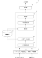
次に、計測精度診断処理について説明する。図6は、この例にかかる軸重計測装置の計測精度診断処理を示すフローチャートである。この計測精度診断処理は、診断タイミングになると実行される。診断タイミングは、例えば、前回の計測精度診断処理の終了から設定時間経過したタイミングであってもよいし、前回の計測精度診断処理の終了から計測区間を走行した車両100の台数が設定台数に達したタイミングであってもよい。この設定台数を1台にすれば、車両100が計測区間を走行する毎に、計測精度診断処理を実行することができる。また、診断タイミングは、上記以外でも、毎週月曜日の午前0:00、毎月1日の午前0:00、偶数月または奇数月の1日の午前0:00等であってもよいし、管理者によって指示されたタイミングであってもよい。
Next, the measurement accuracy diagnosis process will be described. FIG. 6 is a flowchart showing a measurement accuracy diagnosis process of the axle load measuring device according to this example. This measurement accuracy diagnosis process is executed at the diagnosis timing. The diagnosis timing may be, for example, the timing at which the set time has elapsed from the end of the previous measurement accuracy diagnosis process, or the number of
制御ユニット11は、対象車両群を決定する(s11)。この対象車両群に属する車両100の台数は、1台であってもよいが、統計処理の観点から言うと、数千台~数万台であるのが好ましい。例えば、最近1週間の間に計測区間を通過した車両100、最近1か月の間に計測区間を通過した車両100等を、対象車両群に属する車両100にしてもよいし、最後に計測区間を通過した車両100を1台目とし、この車両100に連続する予め定めている台数(数千台~数万台)の車両にしてもよい。また、対象車両群に属する車両100は、車軸の本数で限定してもよい。例えば、対象車両群に属する車両100は、車軸の本数が2本の車両100であるや、車軸の本数が3本以下の車両100である等の条件を設けてもよい。
The
集計部23は、s11で決定した対象車両群に属する車両100毎に、計測値DB14に記憶している計測データを読み出し、輪重センサ2R~4R、2L~4L毎に、対象車両群に属する車両100について計測した輪重の平均値を集計結果として算出する(s12)。
The
ここでは、s12で集計結果として算出された、輪重センサ2Rの平均値をRX1、輪重センサ2Lの平均値をLX1、輪重センサ3Rの平均値をRX2、輪重センサ3Lの集平均値をLX2、輪重センサ4Rの平均値をRX3、輪重センサ4Lの平均値をLX3とする。
Here, the average value of the
判定値算出部24が、s12で、輪重センサ2R~4R、2L~4L毎に、算出された輪重の平均値を用いて、軸重センサ2~4毎に、判定値を算出する(s13)。判定値算出部24によって算出される、軸重センサ2の判定値Y1、軸重センサ3の判定値Y2、および軸重センサ4の判定値Y3は、
Y1=(RX1)/(LX1)
Y2=(RX2)/(LX2)
Y3=(RX3)/(LX3)
である。
The determination
Y1 = (RX1) / (LX1)
Y2 = (RX2) / (LX2)
Y3 = (RX3) / (LX3)
Is.
判定部25は、s13で算出された軸重センサ2の判定値Y1、軸重センサ3の判定値Y2、および軸重センサ4の判定値Y3の中から最大値と最小値を抽出し、その差分を算出する(s14)。s14で算出される差分が、軸重センサ2~4の判定値Y1~Y3のばらつきの大きさである。判定部25は、s14で算出した差分(すなわち、軸重センサ2~4の判定値Y1~Y3のばらつきの大きさ)が、設定されている判定閾値Tthを超えているかどうかを判定する(s15)。
The
判定部25は、s15で判定閾値Tthを超えていると判定すると、計測精度が適正でない軸重センサ2~4が1つ以上あると判定する(s16)。また、判定部25は、s15で判定閾値Tthを超えていないと判定すると、軸重センサ2~4の計測精度が適正であると判定する(s17)。
When the
軸重計測装置1は、出力部15を制御して、s16、またはs17における判定結果を上位装置に出力し(s18)、本処理を終了する。
The axle load measuring device 1 controls the
このように、この例にかかる軸重計測装置1は、各輪重センサ2R~4R、2L~4Lの計測精度が適正であれば、軸重センサ2~4間において、同じ車軸について、一方の輪重センサ2R~4Rで計測された輪重と、他方の輪重センサ2L~4Lで計測された輪重との比が、略同じになることを利用し、軸重センサ2~4の計測精度が適正であるかどうかの判定を行う。したがって、この例にかかる軸重計測装置1は、特殊な車両の走行の有無にかかわらず、車両100の走行方向に並べて配置された軸重センサ2~4の計測精度が適正であるかどうかの判定が行える。
As described above, in the axle load measuring device 1 according to this example, if the measurement accuracy of each
<4.変形例>
上記の例では、s12では集計結果として、輪重センサ2R~4R、2L~4L毎に、計測された輪重の平均値を算出するとしたが、平均値に限らず、例えば、輪重センサ2R~4R、2L~4L毎に、計測された輪重の総和を集計結果として算出してもよいし、輪重センサ2R~4R、2L~4L毎に、計測された輪重の二乗平均平方根を集計結果として算出してもよい。
<4. Modification example>
In the above example, in s12, the average value of the measured wheel weights is calculated for each of the
また、上記したs13における判定値の算出式は、分母と分子を入れ替えてもよい。また、s13で軸重センサ2~4毎に算出する判定値は、一方の輪重センサ2R~4Rの集計結果(計測された輪重の平均値等)から、他方の輪重センサ2L~4Lの集計結果(計測された輪重の平均値等)を差し引いた差分にしてもよい。
Further, in the above-mentioned formula for calculating the determination value in s13, the denominator and the numerator may be exchanged. Further, the judgment value calculated for each
また、s14で算出する軸重センサ2~4の判定値Y1~Y3のばらつきの大きさは、軸重センサ2の判定値Y1、軸重センサ3の判定値Y2、および軸重センサ4の判定値Y3の中から抽出した最大値と最小値との比にしてもよい。
Further, the magnitude of the variation of the judgment values Y1 to Y3 of the
また、上記の例のs15において、s14で算出された軸重センサ2~4の判定値のばらつきの大きさが、判定閾値Tthを超えると判定された場合、s14で最大値、または最小値として抽出されなかった判定値を用いて、計測精度が適正でない軸重センサを特定するようにしてもよい。例えば、最大値として軸重センサ2の判定値Y1が抽出され、最小値として軸重センサ3の判定値Y2が抽出された場合、軸重センサ2の判定値Y1と軸重センサ4の判定値Y3との差分の絶対値Z1を算出するとともに、軸重センサ3の判定値Y2と軸重センサ4の判定値Y3との差分の絶対値Z2を算出する。そして、絶対値Z1と、絶対値Z2とを対比し、絶対値Z1が絶対値Z2よりも小さければ、軸重センサ3の計測精度が適正でないと判定し、反対に絶対値Z1が絶対値Z2よりも大きければ、軸重センサ2の計測精度が適正でないと判定する。すなわち、この判定は、s14で最大値、または最小値として抽出されなかった判定値の軸重センサ2~4を計測精度が適正であると仮定し、計測精度が適正であると仮定した軸重センサ2~4の判定値に対する差がより大きい判定値の軸重センサ2~4を計測精度が適正でないとする判定である。
Further, in s15 of the above example, when it is determined that the magnitude of the variation of the determination values of the
また、判定閾値Tthは、軸重センサ2~4の判定値、およびこれらの判定値のばらつきの大きさを算出する手法に応じて適宜設定すればよい。
Further, the determination threshold value Tth may be appropriately set according to the determination values of the
また、軸重計測装置1は、上述した車両100の各車輪の輪重、車両100の各車軸の軸重、および車両100の重量の計測に加えて、車両100の速度、車両100の軸間距離等の計測も行い、図4に示した算出データに追加的に登録する構成にしてもよい。
Further, in addition to measuring the wheel load of each wheel of the
また、上記の例では、車両100の走行方向に3つの軸重センサ2~4が並べられている例で説明したが、車両100の走行方向に並べられている軸重センサは2本以上であれば、何本であってもよい。
Further, in the above example, the example in which the three
なお、この発明は、上記実施形態そのままに限定されるものではなく、実施段階ではその要旨を逸脱しない範囲で構成要素を変形して具体化できる。また、上記実施形態に開示されている複数の構成要素の適宜な組み合せにより種々の発明を形成できる。例えば、実施形態に示される全構成要素から幾つかの構成要素を削除してもよい。さらに、異なる実施形態に亘る構成要素を適宜組み合せてもよい。 It should be noted that the present invention is not limited to the above-described embodiment as it is, and at the implementation stage, the components can be modified and embodied within a range that does not deviate from the gist thereof. In addition, various inventions can be formed by an appropriate combination of the plurality of components disclosed in the above-described embodiment. For example, some components may be removed from all the components shown in the embodiments. In addition, components from different embodiments may be combined as appropriate.
さらに、この発明に係る構成と上述した実施形態に係る構成との対応関係は、以下の付記のように記載できる。
<付記> 車両(100)の走行方向に並べて配置された複数の軸重センサ(2~4)の計測信号が入力される軸重センサ接続部(12)と、
前記軸重センサ(2~4)毎に、入力された計測信号に応じた計測値を収集する計測値収集部(14)と、
前記軸重センサ(2~4)毎に、収集した計測値を集計して集計結果を取得する集計部(23)と、
前記軸重センサ(2~4)毎に、前記集計結果から判定値を算出する判定値算出部(24)と、
前記判定値を用いて、前記軸重センサ(2~4)の計測精度が適正であるかどうかを判定する判定部(25)と、を備え、
前記軸重センサ(2~4)は、前記車両の幅方向に並べた一対の輪重センサ(2R~4R、2L~4L)を有し、
前記計測値収集部(14)は、前記輪重センサ(2R~4R、2L~4L)毎に、前記計測値を収集し、
前記集計部(23)は、前記輪重センサ(2R~4R、2L~4L)毎に、前記集計結果を取得し、
前記判定値算出部(24)は、前記軸重センサ(2R~4R、2L~4L)毎に、一方の前記輪重センサ(2R~4R)の前記集計結果と、他方の前記輪重センサ(2L~4L)の前記集計結果とが相違している度合を前記判定値として算出し、
前記判定部(25)は、複数の前記軸重センサ(2~4)間における、前記判定値のばらつきによって、前記軸重センサ(2~4)の計測精度が適正であるかどうかを判定する、軸重計測装置(1)。
Further, the correspondence between the configuration according to the present invention and the configuration according to the above-described embodiment can be described as described in the following appendix.
<Additional Notes> The axle load sensor connection unit (12) to which the measurement signals of a plurality of axle load sensors (2 to 4) arranged side by side in the traveling direction of the vehicle (100) are input, and
A measurement value collection unit (14) that collects measurement values according to the input measurement signal for each of the axle load sensors (2 to 4), and a measurement value collection unit (14).
For each axle load sensor (2 to 4), a totaling unit (23) that aggregates the collected measured values and acquires the aggregated result, and
A judgment value calculation unit (24) that calculates a judgment value from the total result for each axle load sensor (2 to 4),
A determination unit (25) for determining whether or not the measurement accuracy of the axle load sensors (2 to 4) is appropriate using the determination value is provided.
The axle load sensors (2 to 4) have a pair of wheel load sensors (2R to 4R, 2L to 4L) arranged in the width direction of the vehicle.
The measured value collecting unit (14) collects the measured values for each of the wheel load sensors (2R to 4R, 2L to 4L).
The totaling unit (23) acquires the totaling result for each of the wheel load sensors (2R to 4R, 2L to 4L).
The determination value calculation unit (24) has, for each of the axle load sensors (2R to 4R, 2L to 4L), the aggregation result of one of the wheel load sensors (2R to 4R) and the other wheel load sensor (2R to 4R). The degree of difference from the tabulation result of 2L to 4L) is calculated as the determination value.
The determination unit (25) determines whether or not the measurement accuracy of the axle load sensors (2 to 4) is appropriate based on the variation in the determination values among the plurality of axle load sensors (2 to 4). , Axial load measuring device (1).
1、1A…軸重計測値
2…軸重センサ
2~4…軸重センサ
2R~4R、2L~4L…輪重センサ
2R…輪重センサ
6、7…車両検知センサ
11…制御ユニット
12…軸重センサ接続部
13…ループコイルセンサ接続部
14…計測値データベース(計測値DB)
15…出力部
21…計測値算出部
22…計測データ生成部
23…集計部
24…判定値算出部
25…判定部
26…閾値設定部
100…車両
1, 1A ... Axle
15 ...
Claims (8)
前記軸重センサ毎に、入力された計測信号に応じた計測値を収集する計測値収集部と、
前記軸重センサ毎に、収集した計測値を集計して集計結果を取得する集計部と、
前記軸重センサ毎に、前記集計結果から判定値を算出する判定値算出部と、
前記判定値を用いて、前記軸重センサの計測精度が適正であるかどうかを判定する判定部と、を備え、
前記軸重センサは、前記車両の幅方向に並べた一対の輪重センサを有し、
前記計測値収集部は、前記輪重センサ毎に、前記計測値を収集し、
前記集計部は、前記輪重センサ毎に、前記集計結果を取得し、
前記判定値算出部は、前記軸重センサ毎に、一方の前記輪重センサの前記集計結果と、他方の前記輪重センサの前記集計結果とが相違している度合を前記判定値として算出し、
前記判定部は、複数の前記軸重センサ間における、前記判定値のばらつきによって、前記軸重センサの計測精度が適正であるかどうかを判定する、軸重計測装置。 The axle load sensor connection part where the measurement signals of multiple axle load sensors arranged side by side in the traveling direction of the vehicle are input, and the axle load sensor connection part.
A measurement value collection unit that collects measurement values according to the input measurement signal for each axle load sensor,
For each axle load sensor, a totaling unit that aggregates the collected measured values and acquires the aggregated result,
For each axle load sensor, a judgment value calculation unit that calculates a judgment value from the total result,
A determination unit for determining whether or not the measurement accuracy of the axle load sensor is appropriate using the determination value is provided.
The axle load sensor has a pair of wheel load sensors arranged in the width direction of the vehicle.
The measured value collecting unit collects the measured value for each wheel load sensor.
The totaling unit acquires the totaling result for each of the wheel load sensors, and obtains the totaling result.
The determination value calculation unit calculates, for each of the axle load sensors, the degree of difference between the aggregated result of one of the wheel load sensors and the aggregated result of the other wheel load sensor as the determination value. ,
The determination unit is an axle load measuring device that determines whether or not the measurement accuracy of the axle load sensor is appropriate based on the variation of the determination value among the plurality of axle load sensors.
前記軸重センサ毎に、収集した計測値を集計して集計結果を取得する集計ステップと、
前記軸重センサ毎に、前記集計結果から判定値を算出する判定値算出ステップと、
前記判定値を用いて、前記軸重センサの計測精度が適正であるかどうかを判定する判定ステップと、を備える計測精度診断方法であって、
前記軸重センサは、前記車両の幅方向に並べた一対の輪重センサを有し、
前記計測値収集ステップは、前記輪重センサ毎に、前記計測値を収集するステップであり、
前記集計ステップは、前記輪重センサ毎に、前記集計結果を取得するステップであり、
前記判定値算出ステップは、前記軸重センサ毎に、一方の前記輪重センサの前記集計結果と、他方の前記輪重センサの前記集計結果とが相違している度合を前記判定値として算出するステップであり、
前記判定ステップは、複数の前記軸重センサ間における、前記判定値のばらつきによって、前記軸重センサの計測精度が適正であるかどうかを判定するステップである、計測精度診断方法。 A measurement value collection step that collects measurement values according to the measurement signals of multiple axle load sensors arranged side by side in the traveling direction of the vehicle, and
For each axle load sensor, a totaling step of totaling the collected measured values and acquiring the totaling result, and
A judgment value calculation step for calculating a judgment value from the total result for each axle load sensor,
A measurement accuracy diagnosis method comprising a determination step of determining whether or not the measurement accuracy of the axle load sensor is appropriate using the determination value.
The axle load sensor has a pair of wheel load sensors arranged in the width direction of the vehicle.
The measured value collecting step is a step of collecting the measured value for each wheel load sensor.
The aggregation step is a step of acquiring the aggregation result for each wheel load sensor.
In the determination value calculation step, the degree of difference between the aggregated result of one of the wheel load sensors and the aggregated result of the other wheel load sensor is calculated as the determination value for each axle load sensor. It's a step
The determination step is a measurement accuracy diagnosis method, which is a step of determining whether or not the measurement accuracy of the axle load sensor is appropriate based on the variation of the determination value among the plurality of axle load sensors.
前記軸重センサ毎に、収集した計測値を集計して集計結果を取得する集計ステップと、
前記軸重センサ毎に、前記集計結果から判定値を算出する判定値算出ステップと、
前記判定値を用いて、前記軸重センサの計測精度が適正であるかどうかを判定する判定ステップと、をコンピュータに実行させる計測精度診断プログラムであって、
前記軸重センサは、前記車両の幅方向に並べた一対の輪重センサを有し、
前記計測値収集ステップは、前記輪重センサ毎に、前記計測値を収集するステップであり、
前記集計ステップは、前記輪重センサ毎に、前記集計結果を取得するステップであり、
前記判定値算出ステップは、前記軸重センサ毎に、一方の前記輪重センサの前記集計結果と、他方の前記輪重センサの前記集計結果とが相違している度合を前記判定値として算出するステップであり、
前記判定ステップは、複数の前記軸重センサ間における、前記判定値のばらつきによって、前記軸重センサの計測精度が適正であるかどうかを判定するステップである、計測精度診断プログラム。 A measurement value collection step that collects measurement values according to the measurement signals of multiple axle load sensors arranged side by side in the traveling direction of the vehicle, and
For each axle load sensor, a totaling step of totaling the collected measured values and acquiring the totaling result, and
A judgment value calculation step for calculating a judgment value from the total result for each axle load sensor,
It is a measurement accuracy diagnosis program that causes a computer to execute a determination step of determining whether or not the measurement accuracy of the axle load sensor is appropriate using the determination value.
The axle load sensor has a pair of wheel load sensors arranged in the width direction of the vehicle.
The measured value collecting step is a step of collecting the measured value for each wheel load sensor.
The aggregation step is a step of acquiring the aggregation result for each wheel load sensor.
In the determination value calculation step, the degree of difference between the aggregated result of one of the wheel load sensors and the aggregated result of the other wheel load sensor is calculated as the determination value for each axle load sensor. It's a step
The determination step is a measurement accuracy diagnosis program, which is a step of determining whether or not the measurement accuracy of the axle load sensor is appropriate based on the variation of the determination value among the plurality of axle load sensors.
Priority Applications (1)
| Application Number | Priority Date | Filing Date | Title |
|---|---|---|---|
| JP2018228714A JP6996482B2 (en) | 2018-12-06 | 2018-12-06 | Axial load measuring device, measurement accuracy diagnosis method, and measurement accuracy diagnosis program |
Applications Claiming Priority (1)
| Application Number | Priority Date | Filing Date | Title |
|---|---|---|---|
| JP2018228714A JP6996482B2 (en) | 2018-12-06 | 2018-12-06 | Axial load measuring device, measurement accuracy diagnosis method, and measurement accuracy diagnosis program |
Publications (2)
| Publication Number | Publication Date |
|---|---|
| JP2020091206A JP2020091206A (en) | 2020-06-11 |
| JP6996482B2 true JP6996482B2 (en) | 2022-01-17 |
Family
ID=71012692
Family Applications (1)
| Application Number | Title | Priority Date | Filing Date |
|---|---|---|---|
| JP2018228714A Active JP6996482B2 (en) | 2018-12-06 | 2018-12-06 | Axial load measuring device, measurement accuracy diagnosis method, and measurement accuracy diagnosis program |
Country Status (1)
| Country | Link |
|---|---|
| JP (1) | JP6996482B2 (en) |
Families Citing this family (1)
| Publication number | Priority date | Publication date | Assignee | Title |
|---|---|---|---|---|
| JP7647188B2 (en) * | 2021-03-10 | 2025-03-18 | オムロン株式会社 | Vehicle weight measurement system, vehicle weight measurement method, and vehicle weight measurement program |
Citations (2)
| Publication number | Priority date | Publication date | Assignee | Title |
|---|---|---|---|---|
| JP5254081B2 (en) | 2009-03-04 | 2013-08-07 | 大和製衡株式会社 | Wheel or axle weight measurement system |
| JP5844085B2 (en) | 2011-08-11 | 2016-01-13 | 大和製衡株式会社 | Axle weight measuring device |
-
2018
- 2018-12-06 JP JP2018228714A patent/JP6996482B2/en active Active
Patent Citations (2)
| Publication number | Priority date | Publication date | Assignee | Title |
|---|---|---|---|---|
| JP5254081B2 (en) | 2009-03-04 | 2013-08-07 | 大和製衡株式会社 | Wheel or axle weight measurement system |
| JP5844085B2 (en) | 2011-08-11 | 2016-01-13 | 大和製衡株式会社 | Axle weight measuring device |
Also Published As
| Publication number | Publication date |
|---|---|
| JP2020091206A (en) | 2020-06-11 |
Similar Documents
| Publication | Publication Date | Title |
|---|---|---|
| JP2010261825A (en) | Weight measurement device for traveling vehicle and sensitivity correction method for weight sensor | |
| JP4720205B2 (en) | Axial load measuring device, axial load measuring system, and measuring accuracy monitoring method | |
| US20220274452A1 (en) | Tire physical information estimation system | |
| CN101754886B (en) | Self-learning autolocation of all tire ID's on a multi-axle vehicle | |
| CN104515687B (en) | Combine the extraction of the tire characteristics of direct TPMS and tire harmonic analysis | |
| US7359776B2 (en) | Apparatus for correcting and diagnosing angular rate sensors installed in an automotive vehicle | |
| US12039812B2 (en) | Tire force estimation system and tire force estimation method | |
| US7963157B2 (en) | Apparatus and method for detecting decrease in tire air pressure and program for detecting decrease in tire air pressure | |
| JP6996481B2 (en) | Axial load measuring device, measurement accuracy diagnosis method, and measurement accuracy diagnosis program | |
| US8108103B2 (en) | Nonlinear frequency dependent filtering for vehicle ride/stability control | |
| JP2004142550A (en) | Body speed measuring device | |
| JP6387536B2 (en) | Calibration apparatus and calibration method | |
| JP5176918B2 (en) | Vehicle roll angle estimation method and apparatus | |
| US8577643B2 (en) | Location determination for individual tires of a multi-tire | |
| US10953900B2 (en) | Abnormality detection device, abnormality detection method, and program | |
| JP6996482B2 (en) | Axial load measuring device, measurement accuracy diagnosis method, and measurement accuracy diagnosis program | |
| KR20130032090A (en) | Weigh-in-motion evaluation system and evaluation method | |
| JP7031571B2 (en) | Axial load measuring device, measurement accuracy diagnosis method, and measurement accuracy diagnosis program | |
| US9903780B2 (en) | Method for detecting an imbalance of a vehicle wheel while the vehicle is rolling | |
| JP3937182B2 (en) | Judgment method of lateral acceleration of car | |
| JP5857481B2 (en) | Tire condition detection method and apparatus | |
| JP7003868B2 (en) | Weight measurement system and vehicle separation method | |
| JP2009047629A (en) | Axle load measuring device | |
| JP2010223755A (en) | Axle load measuring device and axle load measuring method | |
| JP7571526B2 (en) | Axle load measurement device, axle load sensor deterioration estimation method, and axle load sensor deterioration estimation program |
Legal Events
| Date | Code | Title | Description |
|---|---|---|---|
| A621 | Written request for application examination |
Free format text: JAPANESE INTERMEDIATE CODE: A621 Effective date: 20210301 |
|
| TRDD | Decision of grant or rejection written | ||
| A01 | Written decision to grant a patent or to grant a registration (utility model) |
Free format text: JAPANESE INTERMEDIATE CODE: A01 Effective date: 20211116 |
|
| A61 | First payment of annual fees (during grant procedure) |
Free format text: JAPANESE INTERMEDIATE CODE: A61 Effective date: 20211129 |
|
| R150 | Certificate of patent or registration of utility model |
Ref document number: 6996482 Country of ref document: JP Free format text: JAPANESE INTERMEDIATE CODE: R150 |