JP6996481B2 - Axial load measuring device, measurement accuracy diagnosis method, and measurement accuracy diagnosis program - Google Patents
Axial load measuring device, measurement accuracy diagnosis method, and measurement accuracy diagnosis program Download PDFInfo
- Publication number
- JP6996481B2 JP6996481B2 JP2018228713A JP2018228713A JP6996481B2 JP 6996481 B2 JP6996481 B2 JP 6996481B2 JP 2018228713 A JP2018228713 A JP 2018228713A JP 2018228713 A JP2018228713 A JP 2018228713A JP 6996481 B2 JP6996481 B2 JP 6996481B2
- Authority
- JP
- Japan
- Prior art keywords
- axle load
- vehicle
- axle
- measurement
- threshold value
- Prior art date
- Legal status (The legal status is an assumption and is not a legal conclusion. Google has not performed a legal analysis and makes no representation as to the accuracy of the status listed.)
- Active
Links
Images


Landscapes
- Traffic Control Systems (AREA)
Description
この発明は、走行している車両の軸重を計測する軸重センサの計測精度が適正であるかどうかを診断する技術に関する。 The present invention relates to a technique for diagnosing whether or not the measurement accuracy of an axle load sensor that measures an axle load of a traveling vehicle is appropriate.
従来、道路を走行している車両の重量を計測する装置があった。この装置は、車両の走行方向に並べて道路に埋設した複数(2つ以上)の軸重センサの計測信号を処理して、走行している車両の重量を計測する(特許文献1等参照)。軸重センサは、公知のように、車両の車軸毎に、その車軸に取り付けられている車輪が通過するときの垂直力(軸重)の計測に用いるセンサである。 Conventionally, there has been a device for measuring the weight of a vehicle traveling on a road. This device processes the measurement signals of a plurality of (two or more) axle load sensors embedded in the road in the traveling direction of the vehicle to measure the weight of the traveling vehicle (see Patent Document 1 and the like). As is known, the axle load sensor is a sensor used for measuring the normal force (axle load) when a wheel attached to the axle of a vehicle passes through each axle of the vehicle.
車軸の軸重は、車両の走行方向に並べて埋設された複数の軸重センサの計測信号を処理して算出される。例えば、車軸毎に、その車軸について複数の軸重センサで計測された軸重の平均値を、当該車軸の軸重として算出する。また、車両の重量は、その車両の車軸毎に算出された軸重の総和(合計)である。 The axle load of the axle is calculated by processing the measurement signals of a plurality of axle load sensors embedded side by side in the traveling direction of the vehicle. For example, for each axle, the average value of the axle load measured by a plurality of axle load sensors for that axle is calculated as the axle load of the axle. Further, the weight of the vehicle is the total sum (total) of the axle loads calculated for each axle of the vehicle.
また、特許文献1には、車両の重量の計測を中断することなく、軸重センサ毎に、軸重の計測精度に応じて、感度補正を行う構成(補正係数を更新する構成)が記載されている。具体的には、軸重センサ毎に、予め定めた特定車両(軸数、総重量等の車両データが既知である車両)が通過したときの計測データを用いて算出される車両の重量が真値になるように、感度を補正する補正係数を更新している。 Further, Patent Document 1 describes a configuration (a configuration for updating the correction coefficient) in which sensitivity is corrected according to the measurement accuracy of the axle load for each axle load sensor without interrupting the measurement of the weight of the vehicle. ing. Specifically, for each axle load sensor, the weight of the vehicle calculated using the measurement data when a predetermined specific vehicle (vehicle whose vehicle data such as the number of axles and total weight is known) passes is true. The correction coefficient that corrects the sensitivity is updated so that it becomes a value.
しかしながら、特許文献1における特定車両は、
(1)使用状況によって、総重量(各軸の軸重の合計値)が変化しない車両であること、
(2)軸数、軸間距離、軸重などが近似する他の車両が存在しない車両であること、
の条件を満足する車両でなければならない。
However, the specific vehicle in Patent Document 1 is
(1) The vehicle must have a total weight (total axle load of each axle) that does not change depending on usage conditions.
(2) The vehicle must have no other vehicle with similar number of axes, distance between axes, axle load, etc.
It must be a vehicle that satisfies the conditions of.
したがって、貨物を積載するトラック、トレーラ等にかかる車両は、上記(1)の条件を満足しない。また、一般的な乗用車(自家用、および社用)は、上記(2)の条件を満足しない。このことから、特定車両は、一般的な車両ではなく、特殊な車両にせざるを得なかった。特許文献1では、自走式クレーンを特定車両にしている。 Therefore, a vehicle loaded with cargo, such as a truck or a trailer, does not satisfy the condition (1) above. Further, general passenger cars (for private use and for company use) do not satisfy the above condition (2). For this reason, the specific vehicle had to be a special vehicle rather than a general vehicle. In Patent Document 1, a self-propelled crane is used as a specific vehicle.
特定車両が特殊な車両であると、今回の特定車両の走行から、次回の特定車両の走行までの期間が長くなることがある。特許文献1にかかる技術では、軸重センサの計測精度の低下を判定する期間が、今回の特定車両の走行から、次回の特定車両の走行までの期間になる。このため、特許文献1にかかる技術では、長期間にわたって、軸重センサの計測精度が低下しているかどうかを判定することができない事態も生じる。 If the specific vehicle is a special vehicle, the period from the current travel of the specific vehicle to the next travel of the specific vehicle may be long. In the technique according to Patent Document 1, the period for determining the decrease in the measurement accuracy of the axle load sensor is the period from the running of the specific vehicle this time to the running of the next specific vehicle. Therefore, in the technique according to Patent Document 1, it may not be possible to determine whether or not the measurement accuracy of the axle load sensor has deteriorated over a long period of time.
この発明の目的は、特殊な車両の走行の有無にかかわらず、車両の走行方向に並べて配置された軸重センサの計測精度が適正であるかどうかの判定が行える技術を提供することにある。 An object of the present invention is to provide a technique capable of determining whether or not the measurement accuracy of the axle load sensors arranged side by side in the traveling direction of a special vehicle is appropriate regardless of whether or not a special vehicle is traveling.
この発明の軸重計測装置は、上記目的を達成するため以下に示すように構成している。 The axle load measuring device of the present invention is configured as shown below in order to achieve the above object.
軸重センサ接続部には、車両の走行方向に並べて配置された複数の軸重センサの計測信号が入力される。差分算出部は、同じ車軸について、複数の軸重センサから入力された計測信号に応じた計測値の最大値と、最小値との差分を算出する。判定部は、差分算出部が算出した差分の大きさが差分閾値を超えているかどうかを判定する。 Measurement signals of a plurality of axle load sensors arranged side by side in the traveling direction of the vehicle are input to the axle load sensor connection portion. The difference calculation unit calculates the difference between the maximum value and the minimum value of the measured values corresponding to the measurement signals input from the plurality of axle load sensors for the same axle. The determination unit determines whether or not the magnitude of the difference calculated by the difference calculation unit exceeds the difference threshold.
走行している車両は、路面の凹凸、速度、タイヤの空気圧等、様々な要因が複雑に影響しあって振動している。このため、車両の走行方向に並べて配置された複数の軸重センサの計測精度が適正であっても、これらの軸重センサで、同じ車軸について計測した軸重の計測値は、真値(当該車軸の軸重)に対して、ある程度の範囲でばらつく。言い換えれば、車両の走行方向に並べて配置された複数の軸重センサの計測精度が適正であれば、これらの軸重センサで、同じ車軸について計測した軸重の計測値のばらつきは、ある程度の範囲内に収まる。したがって、複数の軸重センサから入力された計測信号に応じた計測値の最大値と、最小値との差分の大きさが差分閾値を超えているかどうかを判定することによって(すなわち、複数の軸重センサで計測した軸重の計測値のばらつきがある程度の範囲内に収まっているかどうかを判定することによって、)、これらの軸重センサの計測精度が適正であるかどうかを判定することができる。 The traveling vehicle vibrates due to various factors such as unevenness of the road surface, speed, and tire pressure. Therefore, even if the measurement accuracy of a plurality of axle load sensors arranged side by side in the traveling direction of the vehicle is appropriate, the measured axle load measured for the same axle load by these axle load sensors is a true value (corresponding to the relevant). It varies to some extent with respect to the axle load of the axle). In other words, if the measurement accuracy of multiple axle load sensors arranged side by side in the traveling direction of the vehicle is appropriate, the variation in the axle load measurements measured for the same axle load by these axle load sensors is within a certain range. It fits inside. Therefore, by determining whether the magnitude of the difference between the maximum value and the minimum value of the measured values according to the measured signals input from the plurality of axle load sensors exceeds the difference threshold value (that is, the plurality of axes). By determining whether the variation in the measured axle load values measured by the weight sensors is within a certain range), it is possible to determine whether the measurement accuracy of these axle load sensors is appropriate. ..
このように、上記構成によれば、特殊な車両の走行の有無にかかわらず、車両の走行方向に並べて配置された軸重センサの計測精度が適正であるかどうかの判定が行える。 As described above, according to the above configuration, it is possible to determine whether or not the measurement accuracy of the axle load sensors arranged side by side in the traveling direction of the vehicle is appropriate regardless of whether or not the special vehicle is traveling.
また、軸重計測装置に、車両の種別を推定する車両種別推定部、およびこの車両種別推定部によって推定された車両の種別に応じて、差分閾値を設定する閾値設定部と、を備える構成にしてもよい。 Further, the axle load measuring device is provided with a vehicle type estimation unit that estimates the vehicle type and a threshold value setting unit that sets a difference threshold value according to the vehicle type estimated by the vehicle type estimation unit. You may.
軸重センサによる軸重の計測誤差は、その軸重の真値に対する割合である。すなわち、軸重が重い車軸ほど、軸重センサによる軸重の計測誤差が大きくなるので、各軸重センサによる軸重の計測値のバラツキの範囲が大きくなる。したがって、車両の種別に応じて差分閾値を設定することによって、軸重センサの計測精度が適正であるかどうかの判定に対する、車両の種別(車両の重量)の違いによる影響を抑えることができる。 The axle load measurement error by the axle load sensor is a ratio of the axle load to the true value. That is, the heavier the axle load, the larger the axle load measurement error by the axle load sensor, and the larger the range of variation in the axle load measurement value by each axle load sensor. Therefore, by setting the difference threshold value according to the vehicle type, it is possible to suppress the influence of the difference in the vehicle type (vehicle weight) on the determination of whether the measurement accuracy of the axle load sensor is appropriate.
また、閾値設定部が車両種別推定部によって推定された車両の種別に応じて、軸重の下限閾値を設定し、判定部が軸重センサ毎に、入力された計測信号に応じた計測値が、下限閾値を超えているかどうかについても判定する構成にしてもよい。このように構成すれば、全ての軸重センサが、計測値が真値に対して軽くなる方向に計測精度が低下しているかどうかの判定も行える。 Further, the threshold value setting unit sets the lower limit threshold value of the axle load according to the vehicle type estimated by the vehicle type estimation unit, and the determination unit sets the measured value according to the input measurement signal for each axle load sensor. , It may be configured to determine whether or not the lower limit threshold value is exceeded. With this configuration, it is possible for all the axle load sensors to determine whether or not the measurement accuracy is lowered in the direction in which the measured value becomes lighter than the true value.
また、閾値設定部が車両種別推定部によって推定された車両の種別に応じて、軸重の上限閾値を設定し、判定部が軸重センサ毎に、入力された計測信号に応じた計測値が、上限閾値を超えているかどうかについても判定する構成にしてもよい。このように構成すれば、全ての軸重センサが、計測値が真値に対して重くなる方向に計測精度が低下しているかどうかの判定も行える。 Further, the threshold value setting unit sets the upper limit threshold value of the axle load according to the vehicle type estimated by the vehicle type estimation unit, and the determination unit sets the measured value according to the input measurement signal for each axle load sensor. , It may be configured to determine whether or not the upper limit threshold value is exceeded. With this configuration, it is possible for all the axle load sensors to determine whether or not the measurement accuracy is lowered in the direction in which the measured value becomes heavier than the true value.
また、車両種別推定部は、撮像装置によって撮像された車両のフレーム画像を処理し、当該車両の種別を推定する構成にしてもよいし、車両の走行方向に並べて配置された複数の軸重センサによる軸重の測定結果に基づいて検出した、当該車両の軸数、および軸間距離によって当該車両の種別を推定してもよい。軸数とは、車両に設けられている車軸の本数である。また、軸間距離とは、車頭側から車尾側に向かう方向において、連続している2つの車軸間の距離である。 Further, the vehicle type estimation unit may be configured to process the frame image of the vehicle captured by the image pickup device and estimate the type of the vehicle, or a plurality of axle load sensors arranged side by side in the traveling direction of the vehicle. The type of the vehicle may be estimated based on the number of axes of the vehicle and the distance between the axes detected based on the measurement result of the axle load. The number of axles is the number of axles provided in the vehicle. The distance between the axles is the distance between two consecutive axles in the direction from the head side to the tail side.
また、軸重センサは、車幅方向に並べた一対の輪重センサであってもよいし、左右に分割されていない一体型のものであってもよい。 Further, the axle load sensors may be a pair of wheel load sensors arranged in the vehicle width direction, or may be an integrated type that is not divided into left and right.
また、車両の走行時に、複数の軸重センサの計測信号を用いて、当該車両の重量を算出する車両重量算出部を備える構成にしてもよい。 Further, the vehicle may be configured to include a vehicle weight calculation unit that calculates the weight of the vehicle by using the measurement signals of the plurality of axle load sensors when the vehicle is traveling.
この発明によれば、特殊な車両の走行の有無にかかわらず、車両の走行方向に並べて配置された軸重センサの計測精度が適正であるかどうかの判定が行える。 According to the present invention, it is possible to determine whether or not the measurement accuracy of the axle load sensors arranged side by side in the traveling direction of the vehicle is appropriate regardless of whether or not the special vehicle is traveling.
以下、この発明の実施形態にかかる軸重計測装置について説明する。 Hereinafter, the axle load measuring device according to the embodiment of the present invention will be described.
<1.適用例>
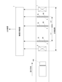
図1は、この例にかかる軸重計測装置を適用した、車両重量計測システムを示す概略図である。図1に示す車両重量計測システムは、軸重計測装置1と、3つの軸重センサ2~4と、2つの車両検知センサ6、7とを備えている。軸重センサ2~4、および車両検知センサ6、7は、軸重計測装置1に接続されている。
<1. Application example>
FIG. 1 is a schematic view showing a vehicle weight measuring system to which the axle load measuring device according to this example is applied. The vehicle weight measuring system shown in FIG. 1 includes an axle load measuring device 1, three
図1に示すように、車両検知センサ6、軸重センサ2、軸重センサ3、軸重センサ4、および車両検知センサ7が、この順番に車両100の走行方向に並べて道路に配置(埋設)されている。車両100の軸重を計測する計測区間は、車両検知センサ6から車両検知センサ7に至る区間である。車両検知センサ6は、計測区間に進入する車両100を検出する。車両検知センサ7は、計測区間から退出する車両100を検出する。
As shown in FIG. 1, the
軸重センサ2は、一対の輪重センサ2R、2Lを、道路を走行する車両100の車幅方向に並べたものである。同様に、軸重センサ3は、一対の輪重センサ3R、3Lを、道路を走行する車両100の車幅方向に並べたものであり、軸重センサ4は、一対の輪重センサ4R、4Lを、道路を走行する車両100の車幅方向に並べたものである。輪重センサ2R~4Rは、車両100の右側の車輪が通過する位置に埋設している。また、輪重センサ2L~4Lは、車両100の左側の車輪が通過する位置に埋設している。輪重センサ2R~4R、2L~4Lは、例えば圧電センサであり、車輪の通過時の押圧力に応じた計測信号を軸重計測装置1に出力する。車両検知センサ6、7は、例えばループコイルセンサであり、インダクタンスの変化を車両検知信号(車両100の有無を示す信号)として軸重計測装置1に出力する。
The
なお、車両検知センサ6、7は、道路に埋設しない、光学式センサ、電波式センサであってもよい。
The
輪重センサ2R~4Rは、計測区間を走行した車両100の車軸毎に、右側の車輪の輪重を計測した計測信号を軸重計測装置1に出力する。また、輪重センサ2L~4Lは、計測区間を走行した車両100の車軸毎に、左側の車輪の輪重を計測した計測信号を軸重計測装置1に出力する。すなわち、軸重計測装置1には、計測区間を走行した車両100の車軸毎に、右側の車輪の輪重について、輪重センサ2Rによる計測信号、輪重センサ3Rによる計測信号、および輪重センサ4Rによる計測信号が入力される。また、軸重計測装置1には、計測区間を走行した車両100の車軸毎に、左側の車輪の輪重について、輪重センサ2Lによる計測信号、輪重センサ3Lによる計測信号、および輪重センサ4Lによる計測信号が入力される。
The
車両100の走行方向における、軸重センサ2と軸重センサ3との距離L1と、軸重センサ3と軸重センサ4との距離L2と、は異なる長さである。走行している車両100は、路面の凹凸、速度、タイヤの空気圧等、様々な要因が複雑に影響しあって振動している。隣接する軸重センサ2と軸重センサ3との距離L1、および隣接する軸重センサ3と軸重センサ4との距離L2の両方が、車両100の振動波長の整数倍に近似すると、軸重の計測誤差が大きくなることがある。このため、この例では、隣接する軸重センサ2と軸重センサ3との距離L1、または隣接する軸重センサ3と軸重センサ4との距離L2の一方が車両100の振動波長の整数倍に近似しても、他方が車両100の振動波長の整数倍に近似しないように、距離L1と、距離L2とを異なる長さにしている。
The distance L1 between the
この例の軸重計測装置1は、輪重センサ2R~4R、2L~4L毎に、入力された計測信号に応じた計測値を蓄積的に記憶する。この例では、この計測値を、入力された計測信号を用いて算出した輪重として説明する。ただし、この計測値は、入力された計測信号に応じた値であればどのような値であってもよい。例えば、この計測値は、入力された計測信号のディジタル値であってもよい。
The axle load measuring device 1 of this example accumulates and stores the measured values corresponding to the input measurement signals for each of the
また、この例において、軸重センサ2の計測精度が適正であるとは、輪重センサ2R、および輪重センサ2Lの計測精度が適正であることを意味する。同様に、軸重センサ3の計測精度が適正であるとは、輪重センサ3R、および輪重センサ3Lの計測精度が適正であることを意味し、軸重センサ4の計測精度が適正であるとは、輪重センサ4R、および輪重センサ4Lの計測精度が適正であることを意味する。また、軸重センサ2によって計測した軸重とは、その車軸に取り付けられている右側の車輪について輪重センサ2Rで計測した輪重と、左側の車輪について輪重センサ2Lで計測した輪重との和である。同様に、軸重センサ3によって計測した軸重とは、その車軸に取り付けられている右側の車輪について輪重センサ3Rで計測した輪重と、左側の車輪について輪重センサ3Lで計測した輪重との和であり、軸重センサ4によって計測した軸重とは、その車軸に取り付けられている右側の車輪について輪重センサ4Rで計測した輪重と、左側の車輪について輪重センサ4Lで計測した輪重との和である。
Further, in this example, the appropriate measurement accuracy of the
走行している車両100が振動しているので、軸重センサ2~4の計測精度が適正であっても、計測された軸重の計測値にばらつきがある。この軸重の計測値のばらつきは、軸重センサ2~4の計測精度が適正であれば、ある程度の範囲に収まる(車両100の振動の大きさによっては、ある程度の範囲に収まらないこともある。)。
Since the traveling
軸重計測装置1は、軸重センサ2~4で同じ車軸について計測された軸重の計測値の最大値と、最小値との差分を算出する。ここで算出される差分は、軸重センサ2~4で同じ車軸について計測された軸重の計測値のばらつきの大きさを示す。軸重計測装置1は、算出した差分が、差分閾値を超えているかどうかを判定することにより、軸重センサ2~4の計測精度が適正であるかどうかを判定する。
The axle load measuring device 1 calculates the difference between the maximum value and the minimum value of the measured axle load measured for the same axle load by the
このように、軸重計測装置1は、特殊な車両の走行の有無にかかわらず、車両の走行方向に並べて配置された軸重センサの計測精度が適正であるかどうかを判定できる。 In this way, the axle load measuring device 1 can determine whether or not the measurement accuracy of the axle load sensors arranged side by side in the traveling direction of the vehicle is appropriate regardless of whether or not the special vehicle is traveling.
<2.構成例>
図2は、この例にかかる軸重計測装置の主要部の構成を示すブロック図である。この例にかかる軸重計測装置1は、制御ユニット11と、軸重センサ接続部12と、ループコイルセンサ接続部13と、計測値データベース14(計測値DB14)と、出力部15と、を備えている。
<2. Configuration example>
FIG. 2 is a block diagram showing a configuration of a main part of the axle load measuring device according to this example. The axle load measuring device 1 according to this example includes a
制御ユニット11は、この例にかかる軸重計測装置1本体各部の動作を制御する。また、制御ユニット11は、計測値算出部21と、計測データ生成部22と、差分算出部23と、判定部24とを有している。また、制御ユニット11は、特に図示していないが、後述する差分閾値を記憶する記憶領域を設けたメモリを有している。また、このメモリには、後述する差分超えカウンタ、および判定軸数カウンタとして機能させる記憶領域が設けられている。制御ユニット11が有する計測値算出部21、計測データ生成部22、差分算出部23、および判定部24の詳細については後述する。
The
軸重センサ接続部12には、接続されている軸重センサ2~4の計測信号が入力される。具体的には、軸重センサ接続部12には、輪重センサ2R~4R、2L~4Lが接続され、各輪重センサ2R~4R、2L~4Lの計測信号が入力される。軸重センサ接続部12は、入力された輪重センサ2R~4R、2L~4Lの計測信号をディジタル値に変換して制御ユニット11に出力する。
The measurement signals of the connected
ループコイルセンサ接続部13には、車両検知センサ6、7が接続されている。ループコイルセンサ接続部13は、車両検知センサ6、7毎に、インダクタンスの変化を検出し、車両100の有無を示す車両検知信号を制御ユニット11に出力する。
計測値DB14は、計測区間を走行した車両100について生成された計測データ、および算出データを蓄積的に記憶するデータベースである。後述する計測データ生成部22が、計測データ、および算出データを生成する。また、計測データ、および算出データの詳細については後述する。
The measured
出力部15は、軸重センサ2~4の計測精度が適正であるかどうかを判定した判定結果、計測区間を走行した車両100の計測データ、および算出データ等を必要に応じて上位装置(不図示)に出力する。
The
次に、制御ユニット11が有する計測値算出部21、計測データ生成部22、差分算出部23、判定部24について説明する。
Next, the measurement
計測値算出部21は、輪重センサ2R~4R、2L~4L毎に、車両100の車輪が輪重センサ2R~4R、2L~4Lを通過したときの計測信号(実際には、軸重センサ接続部12において変換されたディジタル値)を用いて、輪重を算出する。
The measured
計測データ生成部22は、ループコイルセンサ接続部13から入力されている車両検知信号を用いて、計測値算出部21によって算出された輪重を、計測区間を走行した車両100単位で分割する。計測データ生成部22は、軸重センサ2~4毎に計測データを生成する。この例では、計測データ生成部22は、この計測データを車両100単位で生成する。
The measurement
図3は、軸重センサの計測データを示す図である。図3(A)が軸重センサ2の計測データであり、図3(B)が軸重センサ3の計測データであり、図3(C)が軸重センサ4の計測データである。図3(A)~(C)に示す計測データは、同じ車両100についてのものである。この計測データは、図3に示すように車両100を識別する車両IDを対応づけている。この車両IDは、車両100を特定するためのものではなく、計測区間を走行した車両100毎に、軸重センサ2の計測データ、軸重センサ3の計測データ、および軸重センサ4の計測データを、対応づけるものである。
FIG. 3 is a diagram showing measurement data of the axle load sensor. FIG. 3A is the measurement data of the
また、ここでは、車両100の最も車頭側の車軸を第1軸とし、車尾側に向かって、順番に第2軸、第3軸としている。図3に示す各軸重センサ2~4の輪重(右)は、対応する輪重センサ2R~4Rの計測信号を用いて算出した輪重(図中では、RA1、RB1、RC1等で示している。)である。図3に示す各軸重センサ2~4の輪重(左)は、対応する輪重センサ2L~4Lの計測信号を用いて算出した輪重(図中では、LA1、LB1、LC1等で示している。)である。また、図3に示す各軸重センサ2~4の軸重は、対応する輪重センサ2R~4Rの計測信号を用いて算出した輪重と、対応する輪重センサ2L~4Lの計測信号を用いて算出した輪重との和である。
Further, here, the axle on the most head side of the
なお、図3に示す計測データは、車軸が3本である車両100の例である。車軸が2本である車両100の場合、計測データには、第3軸にかかるデータが含まれない。また、車軸が4本以上である車両100の場合、計測データには、車軸の本数に応じて第4軸、第5軸等にかかるデータが含まれる。
The measurement data shown in FIG. 3 is an example of a
また、計測データ生成部22は、図4に示す算出データを生成する。この算出データは、軸重センサ2~4による計測結果に基づいて、算出されたものである。算出データは、図3に示した計測データと同様に、車両100を識別する車両IDを対応づけている。この車両IDは、車両100を特定するためのものではなく、図3に示した計測データと対応づけるものである。図4に示すように、この算出データには、車両100の車軸毎に、輪重(右)、輪重(左)、軸重を登録している。各車軸の輪重(右)は、その車輪の輪重について、輪重センサ2R~4Rの計測信号を用いて算出した輪重の平均値である。また、各車軸の輪重(左)は、その車輪の輪重について、輪重センサ2L~4Lの計測信号を用いて算出した輪重の平均値である。各車軸の軸重は、その車軸の輪重(右)と輪重(左)との和である。また、車両100の重量である車重(ALL)は、その車両100の軸重の総和(合計)である。
Further, the measurement
計測データ生成部22は、車両100毎に生成した、軸重センサ2~4の計測データ、および車両100について算出した算出データを、計測値DB14に登録する。
The measurement
なお、特に図示していないが、図3に示した計測データ、および算出データには、車両100が計測区間を走行したときの日時等も対応づけられている。
Although not particularly shown, the measurement data and the calculation data shown in FIG. 3 are associated with the date and time when the
差分算出部23は、図3に示した計測データを参照し、車両100の車軸毎に、軸重センサ2~4による計測結果である軸重の最大値と、最小値とを抽出し、これらの差分を算出する。図3に示す車両100の第1軸を例にすると、差分算出部23は、軸重センサ2の計測値である(RA1+LA1)、軸重センサ3の計測値である(RA2+LA2)、および軸重センサ4の計測値である(RA3+LA3)の中から、最大値と最小値を抽出し、その差分を算出する。この差分は、対応する車軸に対する、軸重センサ2~4の計測値のばらつきの大きさである。
The
判定部24は、差分算出部23によって算出された差分が、差分閾値を超えているかどうかを判定する。差分閾値は、上記したように、制御ユニット11が有するメモリに記憶している。また、判定部24は、軸重センサ2~4の計測精度が適正であるかどうかについての判定も行う。
The
軸重計測装置1の制御ユニット11は、ハードウェアCPU、メモリ、その他の電子回路によって構成されている。ハードウェアCPUが、この発明にかかる計測精度診断プログラムを実行したときに、計測値算出部21、計測データ生成部22、差分算出部23、および判定部24として動作する。また、メモリは、この発明にかかる計測精度診断プログラムを展開する領域や、この計測精度診断プログラムの実行時に生じたデータ等を一時記憶する領域を有している。さらには、メモリには、上述した差分閾値を記憶する記憶領域、差分超えカウンタ、および判定軸数カウンタとして機能させる記憶領域が設けられている。制御ユニット11は、ハードウェアCPU、メモリ等を一体化したLSIであってもよい。また、ハードウェアCPUが、この発明にかかる計測精度診断方法を実行するコンピュータである。
The
<3.動作例>
この例にかかる軸重計測装置1は、測定区間を走行した車両100について、軸重、および車重を計測する計測処理、および軸重センサ2~4の計測精度が適正であるかどうかを判定する計測精度診断処理を行う。
<3. Operation example>
The axle load measuring device 1 according to this example determines whether or not the axle load and the measurement process for measuring the vehicle weight and the measurement accuracy of the
図5は、この例にかかる軸重計測装置の計測処理を示すフローチャートである。軸重計測装置1は、測定区間に車両100が進入するのを待つ(s1)。制御ユニット11は、ループコイルセンサ接続部13に接続されている車両検知センサ6のインダクタンスの変化により、測定区間に車両100が進入したことを検知する。
FIG. 5 is a flowchart showing a measurement process of the axle load measuring device according to this example. The axle load measuring device 1 waits for the
計測値算出部21は、測定区間に車両100が進入したことが検知されると、軸重センサ接続部12に接続されている輪重センサ2R~4R,2L~4L毎に、計測信号をメモリに蓄積的に記憶する(s2)。すなわち、計測値算出部21は、測定区間に車両100が進入したことが検知されると、輪重センサ2R~4R、2L~4L毎に、計測信号をメモリに蓄積的に記憶する処理を開始する。輪重センサ2R~4R,2L~4Lの計測信号を記憶する時間間隔は、例えば数十msec~数100msecである。
When it is detected that the
計測値算出部21は、測定区間から車両100が退出したことが検出されると(s3)、s2で開始した輪重センサ2R~4R、2L~4L毎に、計測信号をメモリに蓄積的に記憶する処理を終了する(s4)。計測値算出部21は、輪重センサ2R~4R、2L~4L毎に、メモリに蓄積的に記憶した計測信号を処理し、各車軸の輪重の計測値を算出する(s5)。
When it is detected that the
各輪重センサ2R~4R、2L~4Lは、車両100の車輪が通過するときに、計測信号が変化する。したがって、計測値算出部21は、輪重センサ2R~4R、2L~4Lの計測信号が変化した箇所をカウントすることにより、車両100の車軸の本数を得ることができる。また、計測値算出部21は、輪重センサ2R~4R、2L~4L毎に、各車軸の車輪が通過したときの計測信号を抽出し、輪重を算出することができる。
The measurement signals of the
計測データ生成部22は、今回測定区間を通過した車両100について、図3に示した計測データを生成する(s6)。この計測データは、計測値算出部21が輪重センサ2R~4R、2L~4L毎に算出した、各車軸の輪重に基づいて生成できる。また、計測データ生成部22は、図4に示した算出データを生成する(s7)。この算出データは、s6で生成した計測データに基づいて生成できる。すなわち、この算出データも、計測値算出部21が輪重センサ2R~4R、2L~4L毎に算出した、各車軸の輪重に基づいて生成できる。
The measurement
計測データ生成部22は、s6で生成した計測データ、およびs7で生成した算出データを計測値DB14に記憶させ(s8)、s1に戻る。
The measurement
このように、この軸重計測装置1は、測定区間を通過した車両100毎に、図3に示した計測データを計測値DB14に蓄積的に記憶する。また、この軸重計測装置1は、s7で生成した算出データにより、過積載の車両100であるかどうか、左右どちらかに荷物が偏っている偏載状態の車両100であるかどうか等の検出も行える。さらに、計測値DB14に蓄積的に記憶されている算出データは、道路の補修工事等の要否を判断するのに有益な情報として利用できる。
As described above, the axle load measuring device 1 accumulates and stores the measurement data shown in FIG. 3 in the measured
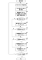
次に、この例にかかる軸重計測装置1の計測精度診断処理について説明する。この計測精度診断処理は、軸重センサ2~4の計測精度が適正であるかどうかを診断する処理である。図6は、計測精度診断処理を示すフローチャートである。軸重計測装置1は、軸重センサ2~4の計測精度を診断する診断タイミングであるかどうかを判定する(s11)。診断タイミングは、例えば、前回の計測精度診断処理の終了から設定時間経過したタイミングであってもよいし、前回の計測精度診断処理の終了から計測区間を走行した車両100の台数が設定台数に達したタイミングであってもよい。この設定台数を1台にすれば、車両100が計測区間を走行する毎に、計測精度診断処理を実行することができる。また、診断タイミングは、上記以外でも、毎週月曜日の午前0:00、毎月1日の午前0:00、偶数月または奇数月の1日の午前0:00等であってもよいし、管理者によって指示されたタイミングであってもよい。
Next, the measurement accuracy diagnosis process of the axle load measuring device 1 according to this example will be described. This measurement accuracy diagnosis process is a process for diagnosing whether or not the measurement accuracy of the
軸重計測装置1は、s11で診断タイミングであると判定すると、対象車両群を決定する(s12)。この対象車両群は、前回の計測精度診断処理の終了から、現時点に至るまでの期間に計測区間を走行した全ての車両100であってもよいし、最後に計測区間を通過した車両100を1台目とし、この車両100に連続する予め定めている台数の車両であってもよい。また、対象車両群に属する車両100は、車軸の本数で限定してもよい。例えば、対象車両群に属する車両100は、車軸の本数が2本の車両100であるや、車軸の本数が3本以下の車両100である等の条件を設けてもよい。軸重計測装置1は、s12で対象車両群を決定すると、集計処理を実行する(s13)。
When the axle load measuring device 1 determines in s11 that the diagnosis timing is reached, the axle load measuring device 1 determines the target vehicle group (s12). This target vehicle group may be all the
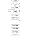
図7は、s13にかかる集計処理を示すフローチャートである。差分算出部23は、s12で決定した対象車両群に属する車両100の車軸の中から判定対象の車軸を決定する(s21)。s21では、s11で決定した対象車両群に属する車両100の車軸の中で、以下に示すs22~s25の処理を行っていない車軸(未処理の車軸)を選択する。差分算出部23は、s21で決定した処理対象の車軸について、軸重センサ2~4で計測された軸重の最大値と、最小値との差分(最大値-最小値)を算出する(s22)。例えば、差分算出部23は、s21で図3に示す計測データの第1軸を判定対象の車軸に決定した場合、軸重センサ2により計測された軸重(RA1+LA1)、軸重センサ3により計測された軸重(RA2+LA2)、および軸重センサ4により計測された軸重(RA3+LA3)の中から、最大値と最小値とを抽出し、その差分を算出する。
FIG. 7 is a flowchart showing the aggregation process related to s13. The
判定部24は、差分算出部23がs22で算出した差分が、差分閾値を超えているかどうかを判定する(s23)。差分閾値は、上記したように制御ユニット11のメモリに記憶されている。走行している車両100は、路面の凹凸、速度、タイヤの空気圧等、様々な要因が複雑に影響しあって振動している。このため、車両100の走行方向に並べて配置された複数の軸重センサ2~4の計測精度が適正であっても、これらの軸重センサ2~4で、同じ車軸について計測した軸重の計測値は、真値(当該車軸の軸重)に対して、ある程度の範囲でばらつく。言い換えれば、車両100の走行方向に並べて配置された複数の軸重センサ2~4の計測精度が適正であれば、これらの軸重センサ2~4で、同じ車軸について計測した軸重の計測値のばらつきは、ある程度の範囲内に収まる。差分閾値は、この範囲の大きさに応じて、予め定めた値である。したがって、s22で算出した差分が、差分閾値を超えていた場合、いずれかの軸重センサ2~4で、軸重が適正に計測されていない可能性が高い。判定部24は、s23で差分閾値を超えていると判定すると、差分超えカウンタのカウント値をインクリメント(カウント値を1カウントアップ)し(s24)、判定軸数カウンタのカウント値をインクリメントする(s25)。また、差分超えカウンタのカウント値、および判定軸数カウンタのカウント値は、s11で診断タイミングであると判定したときに、リセットされている。
The
判定部24は、s23で差分閾値を超えていると判定すると、s24で差分超えカウンタのカウント値をインクリメントすることなく、s25で判定軸数カウンタのカウント値をインクリメントする。
When the
軸重計測装置1は、未処理の車軸の有無を判定し(s26)、未処理の車軸があればs21に戻る。軸重計測装置1は、s26で未処理の車軸がないと判定すると、この集計処理を終了する。 The axle load measuring device 1 determines the presence or absence of an unprocessed axle (s26), and returns to s21 if there is an unprocessed axle. When the axle load measuring device 1 determines in s26 that there is no unprocessed axle, the axle load measuring device 1 ends this aggregation process.
図6に戻って、軸重計測装置1は、s13にかかる集計処理を終了すると、判定部24が判定軸数カウンタのカウント値Xに対する差分超えカウンタのカウント値Yの比率(Y/X)を算出する(s14)。上記の説明から明らかなように、判定軸数カウンタのカウント値Xは、処理対象にした車軸の本数である。また、差分超えカウンタのカウント値Yは、s23で差分閾値を超えていると判定した車軸の本数である。判定部24は、s19で算出した比率が適正比率以下であるかどうかを判定する(s15)。この適正比率は、車両100の振動や、ノイズ等の外的要因により、いずれかの軸重センサ2~4において、軸重が適正に計測されなかった車軸が原因になって、軸重センサ2~4の計測精度が適正でないと誤判定するのを抑制するため、上記の処理で処理対象にした車軸の本数に応じて定めるのが好ましい。例えば、処理対象にした車軸が数本(例えば、2~5本)である場合、0.5程度の比較的大きな値にし、処理対象にした車軸が数100本を超える場合、0.1~0.3程度の比較的小さい値にするのが好ましい。この適正比率も、制御ユニット11のメモリに記憶されている。
Returning to FIG. 6, when the axle load measuring device 1 finishes the aggregation process related to s13, the
判定部24は、s15で適正比率以下であると判定すると、軸重センサ2~4の計測精度が適正であると判定する(s16)。一方、判定部24は、s15で適正比率以下でないと判定すると、軸重センサ2~4の計測精度が適正でないと判定する(s17)。
When the
制御ユニット11は、判定部24による判定結果(s16、またはs17における判定結果)を、出力部15から上位装置に出力し(s18)、本処理を終了する。
The
このように、この例にかかる軸重計測装置1は、特殊な車両の走行の有無にかかわらず、車両100の走行方向に並べて配置された軸重センサ2~4の計測精度が適正であるかどうかの判定が行える。
As described above, in the axle load measuring device 1 according to this example, is the measurement accuracy of the
また、軸重センサ2~4の計測精度を診断する頻度は、診断タイミングの設定によって、車両100が計測区間を走行する毎に行うこともできれば、ある程度の期間毎に行うこともできる。
Further, the frequency of diagnosing the measurement accuracy of the
また、上記の例では、軸重センサ2~4が同じ車軸について計測した軸重の最大値と、最小値との差分が差分閾値を超えているかどうかを判定するとしたが、輪重センサ2R~4Rが同じ車輪について計測した輪重の最大値と、最小値との差分が差分閾値を超えているかどうかを判定してもよい。この場合、輪重センサ2R~4Rの計測精度が適正であるかどうかの診断が行える。同様に、輪重センサ2L~4Lが同じ車輪について計測した輪重の最大値と、最小値との差分が差分閾値を超えているかどうかを判定してもよい。この場合、輪重センサ2L~4Lの計測精度が適正であるかどうかの診断が行える。
Further, in the above example, it is determined whether or not the difference between the maximum value and the minimum value of the shaft weight measured by the
また、上記の例では、軸重センサ2~4は、一対の輪重センサ2R~4R、2L~4Lによって構成されているとしたが、左右に分割されていない一体型のものであってもよい。
Further, in the above example, it is assumed that the
また、軸重計測装置1は、上述した車両100の各車輪の輪重、車両100の各車軸の軸重、および車両100の重量の計測に加えて、車両100の速度、車両100の軸間距離等の計測も行い、図4に示した算出データに追加的に登録する構成にしてもよい。
Further, in addition to measuring the wheel load of each wheel of the
<4.変形例>
次に、別の例にかかる軸重計測装置1Aについて説明する。図8は、別の例にかかる軸重計測装置を適用した、車両重量計測システムを示す概略図である。この例にかかる車両重量計測システムは、カメラ8を備えている点で、上記の例と相違する。カメラ8は、軸重計測装置1Aに接続されており、撮像したフレーム画像を軸重計測装置1Aに出力する。カメラ8は、軸重計測装置1Aにおいて、フレーム画像に撮像されている車両100と、計測区間を走行した車両100との対応づけが行え、且つ撮像されている車両100の種別の推定が行える、フレーム画像の撮像が行えるように設置される。
<4. Modification example>
Next, the axle
この例では、カメラ8は、車両検知センサ6が設置されている周辺を撮像エリアとし、計測区間に進入する(または進入した)車両100全体が収まるフレーム画像の撮像が行えるように設置されている。また、この例では、カメラ8は、車両100を車頭側から俯角を付けて撮像するアングルである。
In this example, the
なお、カメラ8は、計測区間内で、走行している車両100全体が収まるフレーム画像の撮像が行えるように設置されていてもよいし、車両検知センサ7が設置されている周辺で、計測区間から退出する(または退出した)車両100全体が収まるフレーム画像の撮像が行えるように設置されていてもよい。また、カメラ8は、フレーム画像に車両100全体が収まるのであれば、車両100を車尾側から俯角を付けて撮像するアングルであってもよいし、上方から光軸を路面に対してほぼ垂直にしたアングルであってもよいし、路側から光軸を道路の幅方向(走行している車両100の車幅方向)にしたアングルであってもよい。
The
軸重計測装置1Aは、カメラ8のフレーム画像に撮像されている車両100と、計測区間を走行した車両100(軸重を計測した車両100)との対応づけを行う。また、軸重計測装置1は、カメラ8のフレーム画像を処理し、撮像されている車両100の種別を推定する。ここで言う車両100の種別は、車両100の重量(以下、単に車重という場合もある。)で分類したものである。例えば、車両100の種別は、第1種別車両(例えば、乗用車)、第2種別車両(例えば、小型・中型トラック)、第3種別車両(例えば、大型トラック)、および第4種別車両(例えば、トレーラ)の4つである。この例では、第1種別車両は、車重がT1t未満である車両100の種別であり、第2種別車両は、車重がT1t以上~T2t未満の範囲である車両100の種別であり、第3種別車両は、車重がT2t以上~T3t未満の範囲である車両100の種別であり、第4種別車両は、車重がT3t以上である車両100の種別である。但し、T1<T2<T3である。
The axle
なお、車両種別の分類は、上記した4分類に限らず、3分類以下であってもよいし、5分類以上であってもよい。 The classification of vehicle types is not limited to the above-mentioned four classifications, and may be three or less classifications or five or more classifications.
軸重センサ2~4、および車両検知センサ6、7については、上記の例と同様であるのでここでは説明を省略する。
Since the
図9は、この別の例にかかる軸重計測装置1Aの主要部の構成を示すブロック図である。この例にかかる軸重計測装置1Aは、画像入力部16を備えている点、および制御ユニット11に車両種別推定部25を有している点で上記した軸重計測装置1と相違している。画像入力部16には、カメラ8が接続されており、カメラ8が撮像したフレーム画像が入力される。画像入力部16は、カメラ8から入力されたフレーム画像を一時的に記憶しておく、画像メモリ(不図示)を有している。
FIG. 9 is a block diagram showing a configuration of a main part of the axle
制御ユニット11が有する車両種別推定部25は、画像入力部16に入力されたフレーム画像を処理し、このフレーム画像に撮像されている車両100の種別を推定する。車両種別推定部25は、車両100の外形形状、車両100の大きさ(車長(全長)、車高(全高)、または車幅(全幅))等によって、車両100の種別を推定する。
The vehicle
また、この例にかかる軸重計測装置1Aでは、計測データ生成部22が車両種別推定部25によって推定された車両100の種別を、図3に示した計測データ、および図4に示した算出データに対応づける。例えば、車両IDには、対応する車両100の種別を示すコードが含まれている。言い換えれば、計測データ生成部22は、その車両100の種別を示すコードを含む車両IDを生成する。例えば、車両IDの下位数桁が、車両100の種別を示すコードである。
Further, in the axle
なお、車両100の種別を計測データ、および算出データに対応づける手法は、上述した車両IDに含ませる手法に限らず、他の手法であってもよい。
The method of associating the type of the
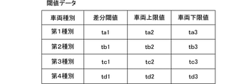
また、この例にかかる軸重計測装置1Aは、制御ユニット11が有するメモリに、上記の例で説明した差分閾値だけでなく、車両上限閾値、および車両下限閾値を記憶している。また、この例では、差分閾値、車両上限閾値、および車両下限閾値を、車両100の種別毎に記憶している。具体的には、図10に示すように、車両100の種別毎に、差分閾値、車両上限閾値、および車両下限閾値を対応付けた閾値データを制御ユニット11のメモリに記憶している。図10に示す例においては、ta1<tb1<tc1<td1であり、ta2<tb2<tc2<td2であり、ta3<tb3<tc3<td4である。
Further, the axle
なお、閾値データとして記憶している車両上限閾値、および車両下限閾値は、その種別の車両100に対するものであり、この発明で言う軸重の上限閾値、および軸重の下限閾値ではない。この発明で言う軸重の上限閾値は、車両100の種別に対応する車両上限閾値を、当該車両100の車軸の本数で除した値である。同様に、この発明で言う軸重の下限閾値は、車両100の種別に対応する車両下限閾値を、当該車両100の車軸の本数で除した値である。このように、この発明で言う軸重の上限閾値、および軸重の下限閾値は、同じ種別の車両100であっても、車軸の本数によって異なる値になる。
The vehicle upper limit threshold value and the vehicle lower limit threshold value stored as the threshold value data are for the
また、この例にかかる軸重計測装置1Aは、上記した例の差分超えカウンタにかえて、後述する集計用カウンタにかかる記憶領域を制御ユニット11のメモリに設けている。
Further, the axle
次に、この例にかかる軸重計測装置1Aの動作について説明する。この例にかかる軸重計測装置1Aも、計測処理、および計測精度診断処理を行う。まず、この例にかかる軸重計測装置1Aの計測処理について説明する。図11は、この例にかかる軸重計測装置1Aの計測処理を示すフローチャートである。
Next, the operation of the axle
軸重計測装置1Aは、計測区間への車両100の進入を検知すると(s31)、各輪重センサ2R~4R、2L~4Lの輪重データの記憶開始する(s32)。軸重計測装置1Aは、計測区間から車両100の退出を検知すると(s33)、各輪重センサ2R~4R、2L~4Lの輪重データの記憶終了する(s34)。軸重計測装置1Aは、輪重センサ2R~4R、2L~4L毎に、車両100の各車軸について、輪重の計測値を算出する(s35)。このs31~s35は、上述した軸重計測装置1のs1~s5にかかる処理と同じである。
When the axle
軸重計測装置1Aは、s1で計測区間への車両100の進入を検知した時点を基準にし、この時点以降にカメラ8によって撮像されたフレーム画像であって、今回計測区間への進入が検知された車両100の全体が撮像されているフレーム画像を処理対象フレーム画像に決定する。車両種別推定部25は、処理対象フレーム画像に撮像されている車両100の種別を推定する(s36)。
The axle
なお、図5においては、s36にかかる処理を、s35にかかる処理の後に行うことになっているが、s31で計測区間への車両100の進入を検知した時点から、s37で計測データの生成を行うまでの間であれば、どのタイミングで実行してもよい。
In FIG. 5, the process related to s36 is to be performed after the process related to s35, but the measurement data is generated in s37 from the time when the entry of the
軸重計測装置1Aは、s37で計測データを生成し、s38で算出データを生成する。s37、およびs38にかかる処理は、上記したs6、およびs7にかかる処理と略同じであるが、生成する計測データ、および算出データに、s36で推定した車両100の種別を対応づける処理を行っている点で相違する。
The axle
軸重計測装置1Aは、s37で生成した計測データ、およびs38で生成した算出データを計測値DB14に記憶させ(s39)、s31に戻る。
The axle
このように、この例にかかる軸重計測装置1Aが実行する計測処理は、カメラ8によって撮像されたフレーム画像を処理して、計測区間を走行した車両100の種別を推定する点、および車両100の種別を計測データ、および算出データに対応づける点で、上記した例の軸重計測装置1が時以降する計測処理と相違している。
As described above, the measurement process executed by the axle
次に、この例にかかる軸重計測装置1Aの計測精度診断処理について説明する。図12は、この例にかかる軸重計測装置の計測精度診断処理を示すフローチャートである。
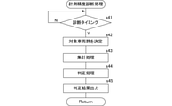
Next, the measurement accuracy diagnosis process of the axle
軸重計測装置1Aは、診断タイミングであると判断すると、対象車両群を決定する(s41、s42)。s41、およびs42にかかる処理は、上記したs11、およびs12にかかる処理と同じである。軸重計測装置1Aは、s42で対象車両群を決定すると、集計処理を実行する(s43)。
When the axle
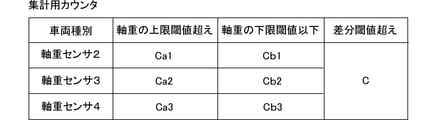
図13は、この例にかかる軸重計測装置の集計処理を示すフローチャートである。この例にかかる軸重計測装置1Aは、図14に示す集計用カウンタとして機能させる記憶領域を制御ユニット11のメモリに設けている。この集計用カウンタでは、軸重センサ2~4毎に、計測値が軸重の上限閾値を超えた車軸の本数(図14中に示すCa1、Ca2、Ca3)、軸重センサ2~4毎に、計測値が軸重の下限閾値以下であった車軸の本数(図14中に示すCb1、Cb2、Cb3)、および差分閾値を超えた車軸の本数(図14中に示すC)をカウントする。
FIG. 13 is a flowchart showing the aggregation process of the axle load measuring device according to this example. The axle
また、この例にかかる軸重計測装置1Aは、上記した軸重計測装置1と同様に、判定軸数カウンタして機能させる記憶領域を制御ユニット11のメモリに設けている。
Further, the axle
差分算出部23は、判定対象の車軸を決定する(s51)。差分算出部23は、s51で決定した判定対象の車軸について、各軸重センサ2~4で計測された軸重の最大値と、最小値との差分を算出する(s52)。s51は、上記したs21と同じ処理であり、s52は、上記したs22と同じ処理である。
The
判定部24は、s51で決定した判定対象の車軸にかかる車両100の種別に応じて、差分閾値、軸重の上限閾値、および軸重の下限閾値を設定する(s53)。判定部24は、図10に示した閾値データを参照して、差分閾値、軸重の上限閾値、および軸重の下限閾値を設定する。具体的には、判定部24は、閾値データにおいて、該当する種別の車両100について対応づけられている差分閾値を、差分閾値に設定する。また、判定部24は、閾値データに登録されている該当する種別の車両100の車両上限閾値を、今回の判定対象の車軸に対応する車両100の軸数(車軸の本数)で除した値を、軸重の上限閾値として設定する。また、判定部24は、閾値データに登録されている該当する種別の車両100の車両下限閾値を、今回の判定対象の車軸に対応する車両100の軸数(車軸の本数)で除した値を、軸重の下限閾値として設定する。この例では、車両100の重量が、その車両100の車軸に均等にかかると仮定し(実際は、均等ではない。)、s53で軸重の上限閾値、および軸重の下限閾値を設定している。
The
判定部24は、s52で算出した差分が、s53で設定した差分閾値を超えていれば、集計用カウンタの差分超えカウント値Cをインクリメントする(s54、s55)。判定部24は、s52で算出した差分が、s53で設定した差分閾値を超えていなければ、s55で、集計用カウンタの差分超えカウント値Cをインクリメントしない。
If the difference calculated in s52 exceeds the difference threshold set in s53, the
また、判定部24は、計測値がs53で設定した軸重の上限閾値を超えている軸重センサ2~4があれば、該当する軸重センサ2~4の上限閾値越えカウント値Ca1、Ca2、Ca3をインクリメントする(s56、s57)。判定部24は、計測値がs53で設定した軸重の上限閾値を超えている軸重センサ2~4が1つもなければ、軸重センサ2~4の上限閾値越えカウント値Ca1、Ca2、Ca3をインクリメントしない。
Further, if the
また、判定部24は、計測値がs53で設定した軸重の下限閾値以下である軸重センサ2~4があれば、該当する軸重センサ2~4の下限閾値以下カウント値Cb1、Cb2、Cb3をインクリメントする(s58、s59)。判定部24は、計測値がs53で設定した軸重の下限閾値以下である軸重センサ2~4が1つもなければ、軸重センサ2~4の下限閾値以下カウント値Cb1、Cb2、Cb3をインクリメントしない。
Further, if the
判定部24は、判定軸数カウンタのカウント値をインクリメントする(s60)。また、集計用カウンタにおいてカウントされる上記各種のカウント値、および判定軸数カウンタにおいてカウントされる判定軸数のカウント値は、s41で診断タイミングであると判定したときに、リセットされる。軸重計測装置1は、未処理の車軸の有無を判定し(s61)、未処理の車軸があればs51に戻る。軸重計測装置1は、s61で未処理の車軸がないと判定すると、この集計処理を終了する。
The
上記説明したように、図13に示した集計処理では、s51で判定対象に決定した車軸の本数を、判定軸数カウンタのカウント値として計数する。また、軸重センサ2~4により計測された軸重の計測値の最大値と、最小値との差分が、差分閾値を超えた車軸の本数を、集計用カウンタの差分超えカウント値Cとして計数する。軸重センサ2~4毎に、計測値が軸重の上限閾値を超えた車軸の本数を、集計用カウンタの上限閾値超えカウント値Ca1、Ca2、Ca3として計数する。さらに、軸重センサ2~4毎に、計測値が軸重の下限閾値以下であった車軸の本数を、集計用カウンタの下限閾値以下カウント値Cb1、Cb2、Cb3として計数する。
As described above, in the aggregation process shown in FIG. 13, the number of axles determined as the determination target in s51 is counted as the count value of the determination axis number counter. Further, the number of axles whose difference between the maximum value and the minimum value of the axle load measured by the
さらに、上述したように、この例にかかる軸重計測装置1は、差分閾値を車両100の種別に応じて設定するとともに、軸重の上限閾値、および軸重の下限閾値を車両100の種別と、その車両100の軸数に応じて設定する。したがって、判定対象に決定した車軸に対して、差分閾値、軸重の上限閾値、および軸重の下限閾値を車両100の種別に応じて設定できる。
Further, as described above, the axle load measuring device 1 according to this example sets the difference threshold value according to the type of the
図12に戻って、判定部24は、s43にかかる集計処理が完了すると、判定処理を実行する(s44)。図15は、s44にかかる判定処理を示すフローチャートである。判定部24は、軸重センサ2~4毎に、上限閾値超え比率を算出する(s71)。s71では、集計用カウンタの上限閾値超えカウント値Ca1、Ca2、Ca3を、判定軸数カウンタのカウント値Xで除した値を算出する。判定部24は、s71で算出した比率の中に、第1比率を超えている軸重センサ2~4があれば、その軸重センサ2~4の計測精度が適正でないと判定する(s72)。
Returning to FIG. 12, the
また、判定部24は、軸重センサ2~4毎に、下限閾値以下比率を算出する(s73)。s73では、集計用カウンタの下限閾値以下カウント値Cb1、Cb2、Cb3を、判定軸数カウンタのカウント値Xで除した値を算出する。判定部24は、s73で算出した比率の中に、第2比率を超えている軸重センサ2~4があれば、その軸重センサ2~4の計測精度が適正でないと判定する(s74)。
Further, the
なお、第1比率と、第2比率とは、同じ値であってもよいし、異なる値であってもよい。 The first ratio and the second ratio may have the same value or different values.
判定部24は、s72、またはs74で、計測精度が適正でないと判定した軸重センサ2~4の有無を判定する(s75)。判定部24は、s72、またはs74で、計測精度が適正でないと判定した軸重センサ2~4があれば、本処理を終了する。この場合、判定部24は、計測精度が適正でない軸重センサ2~4を特定した判定結果を得る。
The
また、判定部24は、s72、またはs74で、計測精度が適正でないと判定した軸重センサ2~4がなければ、差分閾値超え比率を算出する(s76)。s76では、集計用カウンタの差分超えカウント値Cを判定軸数カウンタのカウント値Xで除した値を算出する。判定部24は、s76で算出した差分閾値超え比率が、適正比率以下であれば、軸重センサ2~4の計測精度が適正であると判定し(s77、s78)、本処理を終了する。判定部24は、s76で算出した差分閾値超え比率が、適正比率以下でなければ、軸重センサ2~4の計測精度が適正でないと判定し(s77、s79)、本処理を終了する。判定部24は、s79では、計測精度が適正でない軸重センサ2~4を特定していない判定結果を得る。
Further, the
図12に戻って、軸重計測装置1Aは、s44にかかる判定処理が完了すると、判定部24による判定結果を、出力部15から上位装置に出力し(s45)、本処理を終了する。
Returning to FIG. 12, when the determination process related to s44 is completed, the axle
なお、この例にかかる軸重計測装置1Aの第1比率、第2比率、および適正比率は、上記した例の軸重計測装置1と同様に制御ユニット11のメモリに記憶している。また、第1比率、第2比率、および適正率は、上記の例でも説明したように、車両100の振動や、ノイズ等の外的要因により、いずれかの軸重センサ2~4において、軸重が適正に計測されなかった車軸が原因になって、計測精度が適正でないと誤判定するのを抑制するため、上記の処理で処理対象にした車軸の本数に応じて定めるのが好ましい。例えば、処理対象にした車軸が数本(例えば、2~5本)である場合、比較的大きな値にし、処理対象にした車軸が数100本を超える場合、比較的小さい値にするのが好ましい。
The first ratio, the second ratio, and the appropriate ratio of the axle
このように、この例にかかる軸重計測装置1Aは、車両100の種別に応じて、差分閾値を設定するので、軸重センサ2~4の計測精度が適正であるかどうかの判定に対する、車両100の種別(車両の重量)の違いによる影響を抑えることができる。
As described above, since the axle
また、この例にかかる軸重計測装置1Aは、軸重センサ2~4の計測精度が適正であるかどうかの判定に、軸重の上限閾値、および軸重の下限閾値を用いるので、計測精度が適正でない軸重センサ2~4を特定することも可能になる。また、全ての軸重センサ2~4が、真値に対して計測値が小さくなる方向に同程度低下して計測精度が適正でない状態であったり、真値に対して計測値が大きくなる方向に同程度低下して計測精度が適正でない状態であったりしても、軸重の上限閾値、および軸重の下限閾値を用いたことによって、軸重センサ2~4の計測精度が適正でないと判定できる。
Further, since the axle
なお、この軸重計測装置1Aは、上記した軸重の上限閾値を用いた判定にかかる処理(s71、およびs72)、または軸重の下限閾値を用いた判定にかかる処理(s73、およびs74)の少なくとも一方を実行しない構成にしてもよい。例えば、軸重の上限閾値を用いた判定にかかる処理を行わない場合には、上記したs53で軸重の上限閾値の算出を行わなくてよい。また、s56、s57、s71、s72にかかる処理についても行わなくてよい。また、軸重の下限閾値を用いた判定にかかる処理を行わない場合には、上記したs53で軸重の下限閾値の算出を行わなくてよい。また、s58、s59、s73、s74にかかる処理についても行わなくてよい。
The axle
また、上記の例では、カメラ8で撮像したフレーム画像を処理して車両100の種別を推定するとしたが、車軸の本数(軸数)と軸間距離とに基づいて、車両100の種別を推定してもよい。このように構成すれば、カメラ8を不要にできるとともに、制御ユニット11での画像処理が不要になるので、処理負荷を大幅に低減できる。
Further, in the above example, the type of the
また、上記の例では、車両100の走行方向に3つの軸重センサ2~4が並べられている例で説明したが、車両100の走行方向に並べられている軸重センサは2本以上であれば、何本であってもよい。
Further, in the above example, the example in which the three
なお、上記した全ての例の説明で示したフローチャートにおける各ステップの順番は、あくまでも一例であるので、可能な範囲で入れ替えてもよい。 Since the order of each step in the flowchart shown in the explanation of all the above examples is only an example, they may be replaced to the extent possible.
なお、この発明は、上記実施形態そのままに限定されるものではなく、実施段階ではその要旨を逸脱しない範囲で構成要素を変形して具体化できる。また、上記実施形態に開示されている複数の構成要素の適宜な組み合せにより種々の発明を形成できる。例えば、実施形態に示される全構成要素から幾つかの構成要素を削除してもよい。さらに、異なる実施形態に亘る構成要素を適宜組み合せてもよい。 It should be noted that the present invention is not limited to the above-described embodiment as it is, and at the implementation stage, the components can be modified and embodied within a range that does not deviate from the gist thereof. In addition, various inventions can be formed by an appropriate combination of the plurality of components disclosed in the above-described embodiment. For example, some components may be removed from all the components shown in the embodiments. In addition, components from different embodiments may be combined as appropriate.
さらに、この発明に係る構成と上述した実施形態に係る構成との対応関係は、以下の付記のように記載できる。
<付記>
車両(100)の走行方向に並べて配置された複数の軸重センサ(2~4)の計測信号が入力される軸重センサ接続部(12)と、
同じ車軸について、複数の前記軸重センサ(2~4)から入力された計測信号に応じた計測値の最大値と、最小値との差分を算出する差分算出部(23)と、
前記差分算出部(23)が算出した差分の大きさが差分閾値を超えているかどうかを判定する判定部(24)と、を備えた軸重計測装置(1)。
Further, the correspondence between the configuration according to the present invention and the configuration according to the above-described embodiment can be described as described in the following appendix.
<Additional Notes>
The axle load sensor connection unit (12) to which the measurement signals of the plurality of axle load sensors (2 to 4) arranged side by side in the traveling direction of the vehicle (100) are input, and
For the same axle, a difference calculation unit (23) that calculates the difference between the maximum value and the minimum value of the measured values according to the measurement signals input from the plurality of axle load sensors (2 to 4), and
The axle load measuring device (1) including a determination unit (24) for determining whether or not the magnitude of the difference calculated by the difference calculation unit (23) exceeds the difference threshold value.
1、1A…軸重計測装置
2~4…軸重センサ
2R~4R、2L~4L…輪重センサ
6、7…車両検知センサ
8…カメラ
11…制御ユニット
12…軸重センサ接続部
13…ループコイルセンサ接続部
14…DB
14…計測値データベース(計測値DB)
15…出力部
16…画像入力部
21…計測値算出部
22…計測データ生成部
23…差分算出部
24…判定部
25…車両種別推定部
100…車両
1, 1A ... Axial
14 ... Measured value database (measured value DB)
15 ...
Claims (9)
同じ車軸について、複数の前記軸重センサから入力された計測信号に応じた計測値の最大値と、最小値との差分を算出する差分算出部と、
前記差分算出部が算出した差分の大きさが差分閾値を超えているかどうかを判定する判定部と、を備えた軸重計測装置。 The axle load sensor connection part where the measurement signals of multiple axle load sensors arranged side by side in the traveling direction of the vehicle are input, and the axle load sensor connection part.
A difference calculation unit that calculates the difference between the maximum value and the minimum value of the measured values according to the measurement signals input from the plurality of axle load sensors for the same axle.
An axle load measuring device including a determination unit for determining whether or not the magnitude of the difference calculated by the difference calculation unit exceeds the difference threshold value.
前記車両種別推定部によって推定された前記車両の種別に応じて、前記差分閾値を設定する閾値設定部と、を備えた請求項1に記載の軸重計測装置。 The vehicle type estimation unit that estimates the vehicle type, and the vehicle type estimation unit.
The axle load measuring device according to claim 1, further comprising a threshold value setting unit for setting the difference threshold value according to the vehicle type estimated by the vehicle type estimation unit.
前記判定部は、前記軸重センサ毎に、入力された計測信号に応じた計測値が、前記下限閾値を超えているかどうかについても判定する、請求項2に記載の軸重計測装置。 The threshold value setting unit sets a lower limit threshold value of axle load according to the vehicle type estimated by the vehicle type estimation unit.
The axle load measuring device according to claim 2, wherein the determination unit also determines whether or not the measured value corresponding to the input measurement signal exceeds the lower limit threshold value for each axle load sensor.
前記判定部は、前記軸重センサ毎に、入力された計測信号に応じた計測値が、前記上限閾値を超えているかどうかについても判定する、請求項2、または3に記載の軸重計測装置。 The threshold value setting unit sets an upper limit threshold value for axle load according to the vehicle type estimated by the vehicle type estimation unit.
The axle load measuring device according to claim 2 or 3, wherein the determination unit also determines whether or not the measured value corresponding to the input measurement signal exceeds the upper limit threshold value for each axle load sensor. ..
前記差分算出ステップで算出した差分の大きさが差分閾値を超えているかどうかを判定する判定ステップと、を備えた計測精度診断方法。 A difference calculation step in which a plurality of axle load sensors arranged side by side in the traveling direction of the vehicle calculate the difference between the maximum value and the minimum value of the measured values according to the measurement signals measured for the same axle.
A measurement accuracy diagnosis method comprising a determination step for determining whether or not the magnitude of the difference calculated in the difference calculation step exceeds the difference threshold value.
前記差分算出ステップで算出した差分の大きさが差分閾値を超えているかどうかを判定する判定ステップと、をコンピュータに実行させる計測精度診断プログラム。 A difference calculation step in which a plurality of axle load sensors arranged side by side in the traveling direction of the vehicle calculate the difference between the maximum value and the minimum value of the measured values according to the measurement signals measured for the same axle.
A measurement accuracy diagnostic program that causes a computer to execute a determination step for determining whether or not the magnitude of the difference calculated in the difference calculation step exceeds the difference threshold value.
Priority Applications (1)
| Application Number | Priority Date | Filing Date | Title |
|---|---|---|---|
| JP2018228713A JP6996481B2 (en) | 2018-12-06 | 2018-12-06 | Axial load measuring device, measurement accuracy diagnosis method, and measurement accuracy diagnosis program |
Applications Claiming Priority (1)
| Application Number | Priority Date | Filing Date | Title |
|---|---|---|---|
| JP2018228713A JP6996481B2 (en) | 2018-12-06 | 2018-12-06 | Axial load measuring device, measurement accuracy diagnosis method, and measurement accuracy diagnosis program |
Publications (2)
| Publication Number | Publication Date |
|---|---|
| JP2020091205A JP2020091205A (en) | 2020-06-11 |
| JP6996481B2 true JP6996481B2 (en) | 2022-01-17 |
Family
ID=71013704
Family Applications (1)
| Application Number | Title | Priority Date | Filing Date |
|---|---|---|---|
| JP2018228713A Active JP6996481B2 (en) | 2018-12-06 | 2018-12-06 | Axial load measuring device, measurement accuracy diagnosis method, and measurement accuracy diagnosis program |
Country Status (1)
| Country | Link |
|---|---|
| JP (1) | JP6996481B2 (en) |
Families Citing this family (4)
| Publication number | Priority date | Publication date | Assignee | Title |
|---|---|---|---|---|
| JP7571526B2 (en) * | 2020-12-22 | 2024-10-23 | オムロン株式会社 | Axle load measurement device, axle load sensor deterioration estimation method, and axle load sensor deterioration estimation program |
| CN113654634B (en) * | 2021-09-02 | 2023-01-31 | 山东省计量科学研究院 | A measurement detection method and measurement detection system of a non-stop weighing system |
| CN116576951B (en) * | 2023-05-12 | 2024-01-02 | 中储恒科物联网系统有限公司 | A weighing calculation method for jump weighing belts |
| CN119416672B (en) * | 2025-01-07 | 2025-04-08 | 湖南大学 | Bridge load limiting determination method, system and medium based on actual traffic load |
Citations (3)
| Publication number | Priority date | Publication date | Assignee | Title |
|---|---|---|---|---|
| JP5254081B2 (en) | 2009-03-04 | 2013-08-07 | 大和製衡株式会社 | Wheel or axle weight measurement system |
| JP5566244B2 (en) | 2010-10-01 | 2014-08-06 | 大和製衡株式会社 | Vehicle weighing system |
| JP5844085B2 (en) | 2011-08-11 | 2016-01-13 | 大和製衡株式会社 | Axle weight measuring device |
Family Cites Families (1)
| Publication number | Priority date | Publication date | Assignee | Title |
|---|---|---|---|---|
| JP2012042219A (en) * | 2010-08-12 | 2012-03-01 | Yamato Scale Co Ltd | Wheel and axle weight measurement system |
-
2018
- 2018-12-06 JP JP2018228713A patent/JP6996481B2/en active Active
Patent Citations (3)
| Publication number | Priority date | Publication date | Assignee | Title |
|---|---|---|---|---|
| JP5254081B2 (en) | 2009-03-04 | 2013-08-07 | 大和製衡株式会社 | Wheel or axle weight measurement system |
| JP5566244B2 (en) | 2010-10-01 | 2014-08-06 | 大和製衡株式会社 | Vehicle weighing system |
| JP5844085B2 (en) | 2011-08-11 | 2016-01-13 | 大和製衡株式会社 | Axle weight measuring device |
Also Published As
| Publication number | Publication date |
|---|---|
| JP2020091205A (en) | 2020-06-11 |
Similar Documents
| Publication | Publication Date | Title |
|---|---|---|
| JP6996481B2 (en) | Axial load measuring device, measurement accuracy diagnosis method, and measurement accuracy diagnosis program | |
| KR20100121413A (en) | Weight measuring apparatus of driving vehicle and sensitivity compensating method of weight sensor | |
| JP4720205B2 (en) | Axial load measuring device, axial load measuring system, and measuring accuracy monitoring method | |
| JP6387536B2 (en) | Calibration apparatus and calibration method | |
| JP5176918B2 (en) | Vehicle roll angle estimation method and apparatus | |
| JP6893334B2 (en) | Axis load measuring device and axle load measuring method | |
| US7359776B2 (en) | Apparatus for correcting and diagnosing angular rate sensors installed in an automotive vehicle | |
| JP2017058177A (en) | Measuring device, measuring method, program, and measuring system | |
| JP6948625B2 (en) | Load meter and load measurement method | |
| KR101773262B1 (en) | Non touch-pseudostatic Bridge Weight in motion device and the method of it | |
| JP6996482B2 (en) | Axial load measuring device, measurement accuracy diagnosis method, and measurement accuracy diagnosis program | |
| JP7031571B2 (en) | Axial load measuring device, measurement accuracy diagnosis method, and measurement accuracy diagnosis program | |
| CN111868486B (en) | Axle load measuring device and axle load measuring method | |
| US20240217299A1 (en) | Force sensor diagnosis apparatus,vehicle, and recording medium containing computer program | |
| KR100719856B1 (en) | How to Check and Correct Speed Error of Buried Vehicle Detector Using Automatic Calibration Algorithm | |
| JP7571526B2 (en) | Axle load measurement device, axle load sensor deterioration estimation method, and axle load sensor deterioration estimation program | |
| CN113994216B (en) | Method for calibrating the orientation of an acceleration sensor provided in a vehicle | |
| JP2023127715A (en) | Manhole cover abnormality determination device | |
| JP2018159717A (en) | Calibration device and calibration method | |
| JP5910914B2 (en) | Vehicle roll angle estimation method and apparatus | |
| JP5910915B2 (en) | Vehicle roll angle estimation method and apparatus | |
| CN119207105B (en) | Traffic safety detection method and related device for freight vehicle | |
| EP1702809A2 (en) | Collision detecting apparatus for vehicle | |
| JP6756276B2 (en) | Load measuring device, load measuring method, cracking device and cracking method | |
| JP6443720B2 (en) | Roll angle estimation device for vehicle |
Legal Events
| Date | Code | Title | Description |
|---|---|---|---|
| A621 | Written request for application examination |
Free format text: JAPANESE INTERMEDIATE CODE: A621 Effective date: 20210301 |
|
| TRDD | Decision of grant or rejection written | ||
| A01 | Written decision to grant a patent or to grant a registration (utility model) |
Free format text: JAPANESE INTERMEDIATE CODE: A01 Effective date: 20211116 |
|
| A61 | First payment of annual fees (during grant procedure) |
Free format text: JAPANESE INTERMEDIATE CODE: A61 Effective date: 20211129 |
|
| R150 | Certificate of patent or registration of utility model |
Ref document number: 6996481 Country of ref document: JP Free format text: JAPANESE INTERMEDIATE CODE: R150 |