JP6996450B2 - Image processing equipment, image processing methods, and programs - Google Patents
Image processing equipment, image processing methods, and programs Download PDFInfo
- Publication number
- JP6996450B2 JP6996450B2 JP2018153334A JP2018153334A JP6996450B2 JP 6996450 B2 JP6996450 B2 JP 6996450B2 JP 2018153334 A JP2018153334 A JP 2018153334A JP 2018153334 A JP2018153334 A JP 2018153334A JP 6996450 B2 JP6996450 B2 JP 6996450B2
- Authority
- JP
- Japan
- Prior art keywords
- hand
- virtual
- distance
- real
- space
- Prior art date
- Legal status (The legal status is an assumption and is not a legal conclusion. Google has not performed a legal analysis and makes no representation as to the accuracy of the status listed.)
- Active
Links
Images


Classifications
-
- G—PHYSICS
- G06—COMPUTING OR CALCULATING; COUNTING
- G06F—ELECTRIC DIGITAL DATA PROCESSING
- G06F3/00—Input arrangements for transferring data to be processed into a form capable of being handled by the computer; Output arrangements for transferring data from processing unit to output unit, e.g. interface arrangements
- G06F3/01—Input arrangements or combined input and output arrangements for interaction between user and computer
- G06F3/011—Arrangements for interaction with the human body, e.g. for user immersion in virtual reality
-
- G—PHYSICS
- G06—COMPUTING OR CALCULATING; COUNTING
- G06T—IMAGE DATA PROCESSING OR GENERATION, IN GENERAL
- G06T19/00—Manipulating three-dimensional [3D] models or images for computer graphics
- G06T19/006—Mixed reality
-
- G—PHYSICS
- G06—COMPUTING OR CALCULATING; COUNTING
- G06T—IMAGE DATA PROCESSING OR GENERATION, IN GENERAL
- G06T19/00—Manipulating three-dimensional [3D] models or images for computer graphics
- G06T19/20—Editing of three-dimensional [3D] images, e.g. changing shapes or colours, aligning objects or positioning parts
-
- G—PHYSICS
- G06—COMPUTING OR CALCULATING; COUNTING
- G06T—IMAGE DATA PROCESSING OR GENERATION, IN GENERAL
- G06T2219/00—Indexing scheme for manipulating 3D models or images for computer graphics
- G06T2219/20—Indexing scheme for editing of 3D models
- G06T2219/2016—Rotation, translation, scaling
Landscapes
- Engineering & Computer Science (AREA)
- General Engineering & Computer Science (AREA)
- Theoretical Computer Science (AREA)
- Physics & Mathematics (AREA)
- General Physics & Mathematics (AREA)
- Computer Graphics (AREA)
- Computer Hardware Design (AREA)
- Software Systems (AREA)
- Architecture (AREA)
- Human Computer Interaction (AREA)
- Processing Or Creating Images (AREA)
- User Interface Of Digital Computer (AREA)
Description
本発明は、仮想現実技術に関し、特に、仮想現実空間における視対象の大きさを制御する技術に関する。 The present invention relates to a virtual reality technique, and more particularly to a technique for controlling the size of a visual object in a virtual reality space.
バーチャルリアリティ(VR: virtual reality、「仮想現実」と訳される)とは、対象が観察者の周囲に存在しない(現前していない)にもかかわらず、観察者にその対象が周囲に存在すると感じさせる(同一の知覚表象を生じさせる)技術である(例えば、非特許文献1等参照)。VRを実現するために、知覚表象が現実の3次元空間と実質的に変わらない3次元空間(VR空間、すなわち仮想現実空間)をコンピュータにより生成し、それをヘッドマウントディスプレイ(VRゴーグル)によって観察者に提示することがある。ヘッドマウントディスプレイは、観察者の顔面上部をすっぽりと覆うように装着される映像表示装置である。ヘッドマウントディスプレイは、それを装着した観察者の右眼および左眼の数センチ前にそれぞれ配置される独立の映像表示部を具備し、右眼用画像と左眼用画像とを右眼と左眼とに独立に提示できる。コンピュータが生成したVR空間からヘッドマウントディスプレイで表示される右眼用画像と左眼用画像とを得るために、VR空間内の2つの点を、2点間距離が実際の人間の眼間距離(6.5cm)またはそれに近い値となるように選択する。そして、これらの2つの点に2個のカメラ(VR空間のカメラ)を、それらの撮影方向が平行に同方向を向くようにそれぞれ設置する。実空間(現実空間)のカメラと同じように、VR空間のカメラにも光を受光できる空間範囲(画角)が存在し、そのVR空間のカメラの画角が右眼用画像と左眼用画像とにそれぞれ含まれるVR空間内の空間範囲を決定する。VR空間内に光源と光を反射する表面を持つ対象と対象を撮影するカメラとを配置し、当該対象で反射された光を当該カメラが受光して撮影するシミュレーションを行うことができる。これを撮影シミュレーションと呼ぶ。この撮影シミュレーションの結果として生成されるものが、ヘッドマウントディスプレイに表示される右眼用画像および左眼用画像である。撮影シミュレーションの結果の画像化は、一般的な3DモデリングソフトウェアやVRシミュレーターなどを用いて可能であり、例えばUnity(登録商標)やBlender(登録商標)といった3Dモデリング/レンダリングソフトウェアを用いることができる。撮影シミュレーションから画像化までの処理を自動化することも可能である。
Virtual reality (VR) means that an object does not exist around the observer (it does not exist), but the observer has the object around it. It is a technique that makes you feel (for example, generate the same perceptual representation) (see, for example, Non-Patent
VR空間内における物体の3次元形状はポリゴン(三角形)の集合体によって表現される。VR空間における単位体積当たりのポリゴンの数が少なければ表面形状は粗くなり、逆に、VR空間における単位体積当たりのポリゴンの数が多ければ表面形状はきめ細やかになる。ポリゴンに対し、テクスチャと呼ばれる画像情報を貼り付けることによって、ポリゴンの集合体に色や肌理が表示される。 The three-dimensional shape of an object in VR space is represented by a collection of polygons (triangles). If the number of polygons per unit volume in the VR space is small, the surface shape becomes rough, and conversely, if the number of polygons per unit volume in the VR space is large, the surface shape becomes fine. By pasting image information called a texture on a polygon, the color and texture are displayed on the aggregate of polygons.
VRでは、観察者のリアルな手(実空間における観察者自身の手)と同じ見かけの大きさを持つバーチャルな手(VR空間内に表示される手)の映像を、ヘッドマウントディスプレイによって提示することもできる。ここで「見かけの大きさ」とは、観察者が知覚する手の大きさのことを意味している。例えば、便宜的に実空間におけるリアルな手の中指から手首までの長さを「手の大きさ」として定義すると、通常、手の大きさは18~20cmであるが、バーチャルな手もリアルな手と同じ位の大きさに見えるように設定することができる。VR空間内において手の3次元形状を表現するポリゴン(三角形)の集合体のことを「バーチャルな手のモデル」と呼ぶ時、VR空間におけるバーチャルな手のモデルの大きさを18~20cmに設定すると、バーチャルな手の見かけの大きさはリアルな手の見かけの大きさと同じになる。 In VR, an image of a virtual hand (hand displayed in VR space) having the same apparent size as the observer's real hand (observer's own hand in real space) is presented by a head-mounted display. You can also do it. Here, the "apparent size" means the size of the hand perceived by the observer. For example, if the length from the middle finger to the wrist of a real hand in real space is defined as "hand size" for convenience, the size of the hand is usually 18 to 20 cm, but the virtual hand is also real. It can be set to look as big as a hand. When a collection of polygons (triangles) that express the three-dimensional shape of a hand in VR space is called a "virtual hand model", the size of the virtual hand model in VR space is set to 18 to 20 cm. Then, the apparent size of the virtual hand becomes the same as the apparent size of the real hand.
一方で、VR空間におけるバーチャルな手のモデルの大きさを、リアルな手が通常取りうる大きさの範囲の外に設定すると、バーチャルな手の見かけの大きさはリアルな手の見かけの大きさと一致しない。例えばバーチャルな手のモデルの大きさを10cmに設定すると、VR空間内のバーチャルな手の見かけの大きさはリアルな手の見かけの大きさよりも小さく見える。例えばバーチャルな手のモデルの大きさを40cmに設定すると、VR空間内のバーチャルな手の見かけの大きさはリアルな手の見かけの大きさよりも大きく見える(例えば、非特許文献2等参照)。
On the other hand, if the size of the virtual hand model in the VR space is set outside the range of the size that a real hand can normally take, the apparent size of the virtual hand becomes the apparent size of the real hand. It does not match. For example, if the size of the virtual hand model is set to 10 cm, the apparent size of the virtual hand in the VR space looks smaller than the apparent size of the real hand. For example, when the size of the virtual hand model is set to 40 cm, the apparent size of the virtual hand in the VR space looks larger than the apparent size of the real hand (see, for example, Non-Patent
以降、VR空間におけるバーチャルな手がリアルな手と同じ見かけの大きさをもつ場合、そのバーチャルな手を「バーチャルな普通の手」と表現する。VR空間におけるバーチャルな手がリアルな手よりも見かけ上大きい場合、そのバーチャルな手を「バーチャルな巨人の手」と表現する。VR空間におけるバーチャルな手が、リアルな手よりも見かけ上小さい場合、そのバーチャルな手を「バーチャルな小人の手」と表現する。 Hereinafter, when a virtual hand in VR space has the same apparent size as a real hand, the virtual hand is referred to as a "virtual ordinary hand". When a virtual hand in VR space is apparently larger than a real hand, the virtual hand is referred to as a "virtual giant's hand". When a virtual hand in VR space is apparently smaller than a real hand, the virtual hand is referred to as a "virtual dwarf's hand".
VR空間でバーチャルな巨人の手を表現する方法として、バーチャルな手のモデルの大きさを大きくする方法が考えられる。逆にVR空間でバーチャルな小人の手を表現する方法として、バーチャルな手のモデルの大きさを小さくする方法が考えられる。 As a method of expressing the virtual giant's hand in the VR space, a method of increasing the size of the virtual hand model can be considered. On the contrary, as a method of expressing a virtual dwarf's hand in VR space, a method of reducing the size of the virtual hand model can be considered.
しかし、バーチャルな手のモデルの大きさを変更した場合、バーチャルな手の見かけの質感に問題が生じる場合がある。例えば、VR空間内においてバーチャルな巨人の手を表現するために、バーチャルな手のモデルの大きさの大きくしたと仮定する。このバーチャルな巨人の手をカメラに近づけすぎると、バーチャルな手のモデルが大きすぎてその全貌がカメラの画角に収まらず、結果的にバーチャルな巨人の手がヘッドマウントディスプレイに表示される空間範囲からはみ出してしまう。また、バーチャルな手のモデルの大きさを大きくした場合にはバーチャルな手を構成する単位体積当たりのポリゴン数が減少するため、バーチャルな巨人の手の表面形状は粗くなる。また、ポリゴンに貼るテクスチャの解像度も粗くなる。そのため、例えば、陰影や色、しわ、テクスチャといったバーチャルな巨人の手の質感がリアルな手の質感と大きく異なってしまい、観察者が違和感を感じる。さらには、バーチャルな巨人の手とバーチャルな普通の手とを切り替える場面においてバーチャルな手の質感が大きく変わってしまい、観察者が違和感を感じる。逆に、VR空間でバーチャルな小人の手を表現するために、バーチャルな手のモデルの大きさを小さくしたと仮定する。この場合には、VR空間のカメラで撮影されるバーチャルな小人の手の画像領域が小さくなりすぎてしまい、バーチャルな小人の手の詳細なテクスチャを視認することができなくなってしまう場合がある。さらに、バーチャルな手のモデルの大きさを小さくした場合にはバーチャルな手を構成する単位体積当たりのポリゴン数が増加するため、バーチャルな小人の手の表面形状はきめ細やかになるが、ポリゴンに貼るテクスチャが表示する際の画面の解像度に限界があるため、テクスチャの画素値が隣接する画素間で平均化され、結果的に小人の手に貼られたテクスチャがボケて見える。そのため、バーチャルな小人の手の質感がリアルな手の質感と大きく異なってしまい、観察者が違和感を感じる場合がある。さらには、バーチャルな小人の手とバーチャルな普通の手とを切り替える場面においてバーチャルな手の質感が大きく変わってしまい、観察者が違和感を感じる。 However, resizing the virtual hand model can cause problems with the apparent texture of the virtual hand. For example, in order to represent a virtual giant's hand in VR space, it is assumed that the size of the virtual hand model is increased. If this virtual giant's hand is too close to the camera, the virtual hand model will be too large to fit in the camera's angle of view, resulting in a space where the virtual giant's hand is displayed on the head-mounted display. It goes out of range. In addition, when the size of the virtual hand model is increased, the number of polygons per unit volume constituting the virtual hand decreases, so that the surface shape of the virtual giant's hand becomes rough. In addition, the resolution of the texture attached to the polygon becomes coarse. Therefore, for example, the texture of a virtual giant's hand such as shadows, colors, wrinkles, and textures is significantly different from that of a real hand, and the observer feels uncomfortable. Furthermore, the texture of the virtual hand changes drastically when switching between the virtual giant's hand and the virtual ordinary hand, and the observer feels uncomfortable. On the contrary, it is assumed that the size of the virtual hand model is reduced in order to represent the virtual dwarf's hand in the VR space. In this case, the image area of the virtual dwarf's hand taken by the camera in the VR space becomes too small, and the detailed texture of the virtual dwarf's hand may not be visible. be. Furthermore, if the size of the virtual hand model is reduced, the number of polygons per unit volume that constitutes the virtual hand increases, so the surface shape of the virtual dwarf's hand becomes finer, but polygons. Since there is a limit to the screen resolution when the texture pasted on is displayed, the pixel values of the texture are averaged between adjacent pixels, and as a result, the texture pasted on the hand of a dwarf looks blurred. Therefore, the texture of the virtual dwarf's hand is significantly different from the texture of the real hand, and the observer may feel a sense of discomfort. Furthermore, the texture of the virtual hand changes significantly when switching between the virtual dwarf's hand and the virtual ordinary hand, and the observer feels uncomfortable.
このような問題は、観察者のリアルな手に基づいたバーチャルな手の大きさをリアルな手の大きさと異ならせて観察者に提示する場合やバーチャルな手の大きさを変更して観察者に提示する場合のみならず、ある対象がVR空間において拡大または縮小された視対象を観察者に提示する場合やある対象に対応するVR空間内の視対象を拡大または縮小して観察者に提示する場合にも共通するものである。 Such problems can be solved by presenting the observer with a virtual hand size based on the observer's real hand different from the real hand size, or by changing the virtual hand size. Not only when presenting to the observer, but also when an object presents an enlarged or reduced visual object to the observer in the VR space, or when the visual object in the VR space corresponding to the object is enlarged or reduced and presented to the observer. It is also common when doing.
本発明はこのような点に鑑みてなされたものであり、観察者が知覚する見かけの質感を大きく異ならせることなく観察者に提示するための、ある対象を拡大または縮小したVR空間における視対象を生成することを目的とする。 The present invention has been made in view of such a point, and is a visual object in a VR space in which an object is enlarged or reduced in order to present it to the observer without significantly changing the apparent texture perceived by the observer. The purpose is to generate.
本発明では、実空間または仮想現実空間における第1対象を拡大または縮小して仮想現実空間における視対象である第2対象を生成する。ただし、実空間における実観察位置または仮想現実空間における仮想観察位置で第1対象のなす視角または推定視角である第1視角は、当該仮想観察位置で第2対象のなす視角である第2視角と同一または略同一である。第2対象が第1対象を拡大したものである場合には、当該仮想観察位置から第2対象までの距離である第2距離は、当該実観察位置または仮想観察位置から第1対象までの距離または推定距離である第1距離よりも大きく、第2対象が第1対象を縮小したものである場合には、第2距離は第1距離よりも小さい。 In the present invention, the first object in the real space or the virtual reality space is enlarged or reduced to generate the second object which is the visual object in the virtual reality space. However, the first viewing angle, which is the viewing angle or estimated viewing angle of the first object at the actual observation position in the real space or the virtual observation position in the virtual real space, is the same as the second viewing angle, which is the viewing angle of the second object at the virtual observation position. Same or almost identical. When the second object is an enlargement of the first object, the second distance, which is the distance from the virtual observation position to the second object, is the distance from the actual observation position or the virtual observation position to the first object. Or, if it is larger than the first distance, which is the estimated distance, and the second object is a reduced version of the first object, the second distance is smaller than the first distance.
これにより、観察者が知覚する見かけの質感を大きく異ならせることなく観察者に提示するための、ある対象を拡大または縮小したVR空間における視対象を生成できる。 This makes it possible to generate a visual object in a VR space in which an object is enlarged or reduced so as to be presented to the observer without significantly differentiating the apparent texture perceived by the observer.
以下、図面を参照して本発明の実施形態を説明する。
[原理]
まず、本実施形態で説明する技術の原理を説明する。ここでは、観察者のリアルな手に基づくバーチャルな手の大きさをリアルな手の大きさと異ならせて知覚させる場合について説明する。
Hereinafter, embodiments of the present invention will be described with reference to the drawings.
[principle]
First, the principle of the technique described in this embodiment will be described. Here, a case is described in which the size of a virtual hand based on the observer's real hand is perceived differently from the size of the real hand.
本技術では、大きさ恒常性を利用することで、バーチャルな手の質感をリアルな手の質感と大きく異ならせずに、バーチャルな手をリアルな手よりも大きく見せたり小さく見せたりする。大きさ恒常性とは、対象の奥行きを考慮して対象の大きさを判断する脳(視覚)の特性を意味する。人間は世界から光を受容する。その受容器は目である。目の奥には網膜と呼ばれる部位があり、目を通過してきた光が網膜に当たる。網膜にある網膜細胞が光によって刺激され、刺激を受けた網膜細胞からの信号が神経繊維を通じて脳に伝わる。その信号が脳において更に情報処理されることにより、人間は世界を見ることができる。脳は、対象の大きさを直接測定することはできないので、網膜に当たった光のパタンの大きさに基づいて対象の大きさを判断する。このとき、網膜に当たった光のパタンの大きさは対象がなす視角に対応する。図2は、観察者の左右の目のうち、左眼が同じ大きさの対象である物体aおよび物体bを見ている状況を例示している。左眼で物体aがなす視角は、図2における角AOA’であり、左眼で物体bがなす視角は図2における角BOB’である。なお、点Oは左眼の水晶体内部に位置する原点を表す。図2では物体aと物体bとが同じ大きさであるが、物体bの方が物体aよりも左眼から遠い位置にある。この場合、物体bの視角は物体aの視角よりも小さい。つまり、角AOA’>角BOB’である。しかしながら、図2のような事態に遭遇したときであっても、観察者は物体aと物体bの大きさが等しいと判断できる。この観察者による大きさ判断を理解するためには、脳による奥行き推定と大きさ推定の関係性を理解することが必要である。 In this technology, by using size homeostasis, the texture of a virtual hand does not differ significantly from the texture of a real hand, and the virtual hand looks larger or smaller than the real hand. Size homeostasis means a characteristic of the brain (visual sense) that determines the size of an object in consideration of the depth of the object. Humans receive light from the world. The receptor is the eye. There is a part called the retina in the back of the eye, and the light that has passed through the eye hits the retina. The retinal cells in the retina are stimulated by light, and signals from the stimulated retinal cells are transmitted to the brain through nerve fibers. When the signal is further processed in the brain, humans can see the world. Since the brain cannot directly measure the size of an object, it determines the size of the object based on the size of the pattern of light that hits the retina. At this time, the size of the pattern of light that hits the retina corresponds to the viewing angle of the object. FIG. 2 illustrates a situation in which the left eye of the observer's left and right eyes is looking at an object a and an object b of the same size. The viewing angle formed by the object a with the left eye is the angle AOA'in FIG. 2, and the viewing angle formed by the object b with the left eye is the angle BOB'in FIG. 2. The point O represents the origin located inside the crystalline lens of the left eye. In FIG. 2, the object a and the object b have the same size, but the object b is located farther from the left eye than the object a. In this case, the viewing angle of the object b is smaller than the viewing angle of the object a. That is, the angle of attack AOA'> the angle of attack BOB'. However, even when the situation as shown in FIG. 2 is encountered, the observer can determine that the sizes of the object a and the object b are equal. In order to understand the size judgment by this observer, it is necessary to understand the relationship between the depth estimation and the size estimation by the brain.
まず、脳は右眼と左眼に映る像のずれ(両眼視差)から奥行きを推定することができる。また、2つの対象が存在する場合、その2つの対象が生成する両眼視差の関係性(相対視差)から、2つの対象のどちらが遠くにあるかを推定することができる。例えば、図2において物体bを注視した場合、物体aは交差性視差を生成し、注視点である物体bは両眼視差を生成しない(すなわち、物体bが生成する両眼視差は零になる)。一般に脳は、交差性視差を生成する対象が両眼視差を生成しない対象よりも手前にあると推定するため、物体aは注視された物体bよりも手前にあると認識される。一方で、例えば、図2において物体aを注視した場合、物体bは非交差性視差を生成し、注視点である物体aは両眼視差を生成しない(すなわち、物体aが生成する両眼視差は零になる)。一般に脳は、非交差性視差を生成する対象が両眼視差を生成しない対象よりも奥まっていると推定するため、物体bは注視された物体aよりも奥まっていると認識される。このように脳は両眼視差を奥行き情報として用いることで、物体bが物体aよりも遠くにあることを認識することができる。 First, the brain can estimate the depth from the difference between the images reflected in the right eye and the left eye (binocular parallax). Further, when two objects exist, it is possible to estimate which of the two objects is farther from the relationship (relative parallax) of the binocular parallax generated by the two objects. For example, when the object b is gazed in FIG. 2, the object a produces cross-sectional parallax, and the object b which is the gazing point does not generate binocular parallax (that is, the binocular disparity generated by the object b becomes zero). ). In general, the brain presumes that the object that produces cross-parallax is in front of the object that does not generate binocular parallax, so that the object a is recognized as being in front of the gaze object b. On the other hand, for example, when the object a is gazed in FIG. 2, the object b produces non-crossing parallax, and the object a which is the gazing point does not generate binocular parallax (that is, the binocular parallax generated by the object a). Will be zero). In general, the brain presumes that the object that produces non-crossing parallax is deeper than the object that does not generate binocular parallax, so that the object b is recognized as being deeper than the gaze object a. In this way, the brain can recognize that the object b is farther than the object a by using the binocular parallax as the depth information.
次に、この奥行き推定に基づいて、脳が物体aと物体bの大きさをどのように判断するかという点について説明する。脳は、網膜に当たった物体bの光のパタンが物体aの光のパタンよりも小さいことから、物体bが生成する視角(角BOB’)は、物体aが生成する視角(角AOA’)よりも小さいと認識する。脳はまた、前述の奥行き推定により、物体bが物体aよりも遠くにあることを認識する。さらに、一般に脳は、遠くにあるものはそれが近くにあるときよりも小さく見えるという事前知識を持っている。脳は、このような視角および奥行きについての認識と事前知識との関係性から、物体aと物体bとが同じ大きさであることが最も確からしいと判断する。これが大きさ恒常性の働きである。 Next, how the brain determines the sizes of the object a and the object b based on this depth estimation will be described. Since the light pattern of the object b that hits the retina of the brain is smaller than the light pattern of the object a, the visual angle generated by the object b (angle BOB') is the visual angle generated by the object a (angle AOA'). Recognize that it is smaller than. The brain also recognizes that the object b is farther than the object a by the above-mentioned depth estimation. Moreover, the brain generally has the prior knowledge that what is far away looks smaller than when it is near. The brain determines that it is most probable that the object a and the object b are the same size from the relationship between the recognition of the visual angle and the depth and the prior knowledge. This is the function of size homeostasis.
図3は、観察者の左右の目のうち、左眼が大きさの異なる対象である物体cおよび物体fを見ている状況を例示している。左眼で物体cのなす視角は角COC’であり、左眼で物体fのなす視角は角FOF’である。角COC’は角FOF’と等しい。また、物体fは物体cよりも大きく、物体fの方が物体cよりも左眼から遠い位置にある。この時、脳は、網膜に当たった物体cの光のパタンが物体fの光のパタンと同じ大きさであることから、FOF’=COC’であると認識する。脳はまた、前述の奥行き推定により、物体fが物体cよりも遠くにあることを認識する。さらに脳は、上述の事前知識を持っている。これらより、脳は、物体cと物体fとで視角は同じだけれど、物体fの方が物体cよりも遠くにあるから、物体fの方が物体cよりも実際の大きさは大きいだろうと推測する。これも大きさ恒常性の働きである。 FIG. 3 illustrates a situation in which the left eye of the left and right eyes of the observer is looking at an object c and an object f having different sizes. The viewing angle formed by the object c with the left eye is the angle COC', and the viewing angle formed by the object f with the left eye is the angle FOF'. The angle COC'is equal to the angle FOF'. Further, the object f is larger than the object c, and the object f is located farther from the left eye than the object c. At this time, the brain recognizes that FOF'= COC' because the pattern of light of the object c that hits the retina is the same as the pattern of light of the object f. The brain also recognizes that the object f is farther than the object c by the above-mentioned depth estimation. In addition, the brain has the above-mentioned prior knowledge. From these, the brain has the same viewing angle between the object c and the object f, but since the object f is farther than the object c, the actual size of the object f will be larger than that of the object c. Infer. This is also a function of size homeostasis.
本技術では、実空間で移動するリアルな手を観察者が観察した際のリアルな手の視角とVR空間内のカメラで撮影したバーチャルな手の視角とを一致させつつ、脳が感じるバーチャルな手の奥行き位置を両眼視差に基づいて操作する。これにより、バーチャルな手の質感をリアルな手の質感と大きく異ならせずに、バーチャルな手を見かけ上、リアルな手よりも大きく見せたり小さく見せたりする。 In this technology, the virtual hand that the brain feels while matching the real hand viewing angle when the observer observes the real hand moving in the real space with the virtual hand viewing angle taken by the camera in the VR space. Operate the depth position of the hand based on binocular disparity. This makes the virtual hand look larger or smaller than the real hand, without making the texture of the virtual hand significantly different from the texture of the real hand.
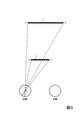
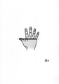
まず、本技術において、バーチャルな手を見かけ上、リアルな手よりも大きく見せる場合、すなわちバーチャルな巨人の手を提示する場合について説明する。図4に例示するように、以降の説明では、便宜上、右手親指の先端から右手小指の付け根までの距離(LからL’までの線形寸法)を「手の大きさ」と定義して視角を計算する。視角を計算するために利用した手の部分を基準部と呼び、基準部の長さ(線形寸法)を基準距離と呼ぶ。基準距離のなす視角が手の視角である。また、基準部を水平線分によって表現する。図5Aに、本技術において、観察者の目からリアルな手までの奥行きが変化する場合における当該リアルな手の視角変化を例示し、図5Bに、このリアルな手に基づいたバーチャルな手のカメラからの奥行きが変化する場合における当該バーチャルな手の視角変化を例示する。観察者の目の原点Oからリアルな手の3次元形状までの距離(例えば、原点Oからリアルな手の3次元形状の中心点までの距離)を「リアルな手の奥行き距離」と表現し、VR空間を撮影するカメラの結像面Iに位置する原点OI(例えば、焦点)からバーチャルな手までの距離(例えば、原点OIからバーチャルな手の3次元形状の中心点までの距離)を「バーチャルな手の奥行き距離」と表現する。krはリアルな手の奥行き距離を表し、kvはバーチャルな手の奥行き距離を表す。本技術では、バーチャルな手を、リアルな手の実空間での移動に伴ってVR空間内を移動させる。すなわち、バーチャルな手をリアルな手と終始同時に移動させる。例えば、リアルな手が実空間の位置Pr1から位置Pr2へ移動すると、それに伴ってバーチャルな手をVR空間の位置Pv1から位置Pv2へ移動させる。リアルな手およびバーチャルな手の移動に伴い、リアルな手の奥行き距離kr、およびバーチャルな手の奥行き距離kvが変化する。ただし、リアルな手の奥行き距離krと当該リアルな手に基づいたバーチャルな手の奥行き距離kvとの比は常に一定である。図5Aにおける水平線分Er1-E’r1は、リアルな手が実空間の位置Pr1に配置された際のリアルな手の基準部を例示し、水平線分Er2-E’r2は、リアルな手が実空間の位置Pr2に配置された際のリアルな手の基準部を例示している。また、図5Bにおける水平線分Ev1-E’v1は、リアルな手が位置Pr1に配置された際に位置Pv1に配置されるバーチャルな手の基準部を例示している。水平線分Ev2-E’v2は、リアルな手が位置Pr2に配置された際に位置Pv2に配置されるバーチャルな手の基準部を例示している。 First, in the present technology, a case where a virtual hand looks larger than a real hand, that is, a case where a virtual giant's hand is presented will be described. As illustrated in FIG. 4, in the following description, for convenience, the distance from the tip of the right thumb to the base of the right little finger (linear dimension from L to L') is defined as "hand size" to define the viewing angle. calculate. The part of the hand used to calculate the viewing angle is called the reference part, and the length (linear dimension) of the reference part is called the reference distance. The viewing angle formed by the reference distance is the viewing angle of the hand. In addition, the reference part is represented by a horizontal line segment. FIG. 5A illustrates a change in the visual angle of the real hand when the depth from the observer's eyes to the real hand changes in the present technology, and FIG. 5B shows a virtual hand based on the real hand. An example shows a change in the visual angle of the virtual hand when the depth from the camera changes. The distance from the origin O of the observer's eyes to the 3D shape of the real hand (for example, the distance from the origin O to the center point of the 3D shape of the real hand) is expressed as "real hand depth distance". , The distance from the origin O I (for example, the focal point) located on the image plane I of the camera that captures the VR space to the virtual hand (for example, the distance from the origin O I to the center point of the three-dimensional shape of the virtual hand). ) Is expressed as "virtual hand depth distance". k r represents the real depth distance of the hand, and k v represents the virtual depth distance of the hand. In this technology, a virtual hand is moved in the VR space as the real hand moves in the real space. That is, the virtual hand is moved at the same time as the real hand from beginning to end. For example, when a real hand moves from the position Pr1 in the real space to the position Pr2 , the virtual hand moves from the position Pv1 in the VR space to the position Pv2 accordingly. With the movement of the real hand and the virtual hand, the depth distance kr of the real hand and the depth distance kv of the virtual hand change. However, the ratio of the real hand depth distance kr to the virtual hand depth distance kv based on the real hand is always constant. The horizontal line segment E r1 - E'r1 in FIG. 5A exemplifies a real hand reference portion when a real hand is placed at the position Pr1 in the real space, and the horizontal line segment E r2 - E'r2 is a real hand. Illustrates a real hand reference when a hand is placed at position Pr2 in real space. Further, the horizontal line segment E v1 - E'v1 in FIG. 5B exemplifies a virtual hand reference portion placed at the position P v1 when the real hand is placed at the position Pr1 . The horizon segment E v2 - E'v2 exemplifies a virtual hand reference that is placed at position P v2 when a real hand is placed at position Pr2 .
リアルな手が実空間内を移動すると、リアルな手の奥行き距離が変化する。図5Aの例の場合、位置Pr1に配置されたリアルな手の奥行き距離は、位置Pr2に配置されたリアルな手の奥行き距離よりも小さい。リアルな手の基準距離が変化しないので、水平線分Er1-E’r1の線形寸法と水平線分Er2-E’r2の線形寸法は等しい。この場合、原点Oで位置Pr1のリアルな手のなす視角(破線がなす角)Er1OE’r1は、位置Pr2のリアルな手のなす視角(実線がなす角)Er2OE’r2よりも大きい。しかしながら、たとえ実空間でリアルな手が位置Pr1から位置Pr2へ移動したり、位置Pr2から位置Pr1へ移動したりしても、観察者はリアルな手が小さくなったり大きくなったりしたとは感じず、同じ大きさのリアルな手の奥行きが自然に変化したと感じる。 As the real hand moves in the real space, the depth distance of the real hand changes. In the case of the example of FIG. 5A, the depth distance of the real hand arranged at the position Pr1 is smaller than the depth distance of the real hand arranged at the position Pr2 . Since the reference distance of the real hand does not change, the linear dimension of the horizontal line segment Er1-E'r1 and the linear dimension of the horizontal line segment Er2 - E'r2 are equal. In this case, the real hand-made viewing angle (angle formed by the broken line) E r1 OE'r1 at the origin O is the real hand-made viewing angle (solid line formed) E r2 OE'r2 at the position Pr2 . Greater than. However, even if the real hand moves from the position Pr1 to the position Pr2 or from the position Pr2 to the position Pr1 in the real space, the observer can make the real hand smaller or larger. I don't feel like I did it, but I feel that the depth of a realistic hand of the same size changed naturally.
図5Bに例示するように、本技術では、バーチャルな手をリアルな手の移動に伴って移動させ、バーチャルな手の奥行き距離kvをリアルな手の奥行き距離krに伴って変化させる。ここで、位置Pv1に配置されたバーチャルな手の奥行き距離は、位置Pv2に配置されたバーチャルな手の奥行き距離よりも小さい。図5Bに例示すように、本技術では、バーチャルな手の基準距離は常に一定とし、水平線分Ev1-E’v1の線形寸法と水平線分Ev2-E’v2の線形寸法を等しくする。この場合、原点OIで位置Pv1のバーチャルな手のなす視角(破線がなす角)Ev1OIE’v1は、位置Pv2のバーチャルな手のなす視角(実線がなす角)Ev2OIE’v2よりも大きい。しかしながら、本技術によってVR空間でバーチャルな手を位置Pv1から位置Pv2へ移動させたり、位置Pv2から位置Pv1へ移動させたりしても、観察者はバーチャルな手が小さくなったり大きくなったりしたとは感じず、同じ大きさのバーチャルな手の奥行きが自然に変化したと感じさせることができる。 As illustrated in FIG. 5B, in the present technology, the virtual hand is moved with the movement of the real hand, and the depth distance kv of the virtual hand is changed with the depth distance kr of the real hand. Here, the depth distance of the virtual hand placed at the position P v1 is smaller than the depth distance of the virtual hand placed at the position P v2 . As shown in FIG. 5B as an example, in the present technique, the reference distance of the virtual hand is always constant, and the linear dimension of the horizontal line segment E v1 - E'v1 and the linear dimension of the horizontal line segment E v2 - E'v2 are made equal. In this case, the viewing angle formed by the virtual hand at the origin OI (angle formed by the broken line) E v1 OIE'v1 is the viewing angle formed by the virtual hand formed by the virtual hand at the position Pv2 (angle formed by the solid line) E v2 . Greater than OIE'v2 . However, even if the virtual hand is moved from the position P v1 to the position P v2 or from the position P v2 to the position P v1 in the VR space by this technology, the observer can make the virtual hand smaller or larger. You can feel that the depth of a virtual hand of the same size has changed naturally, without feeling that it has become loose.
また、本技術では、原点OIで位置Pv1のバーチャルな手のなす視角(図5Bの破線がなす角)Ev1OIE’v1を、原点Oで位置Pr1のリアルな手のなす視角(図5Aの破線がなす角)Er1OE’r1と一致させる。さらに、本技術では、リアルな手の位置Pr1から位置Pr2への移動に伴うリアルな手のなす視角の変化と、バーチャルな手の位置Pv1から位置Pv2への移動に伴うバーチャルな手のなす視角の変化が等しくなるようにする。よって、本技術では、リアルな手の位置Pr1から位置Pr2の方向への移動に伴ってバーチャルな手を位置Pv1から位置Pv2の方向へ移動させる場合に、バーチャルな手のなす視角をリアルな手のなす視角と常に一致させている。同様に、本技術では、原点OIで位置Pv2のバーチャルな手のなす視角(図5Bの実線がなす角)Ev2OIE’v2を、原点Oで位置Pr2のリアルな手のなす視角(図5Aの実線がなす角)Er2OE’r2と一致させる。さらに、本技術では、リアルな手の位置Pr2から位置Pr1への移動に伴うリアルな手のなす視角の変化と、バーチャルな手の位置Pv2から位置Pv1への移動に伴うバーチャルな手のなす視角の変化が等しくなるようにする。よって、本技術では、リアルな手の位置Pr2から位置Pr1の方向への移動に伴ってバーチャルな手を位置Pv2から位置Pv1の方向へ移動させる場合にも、バーチャルな手のなす視角をリアルな手のなす視角と常に一致させている。以上より、本技術では、バーチャルな手のなす視角をリアルな手のなす視角と常に一致させている。このようにすることで、本技術では、バーチャルな手の見かけの質感を、常時、リアルな手の見かけの質感と同等になるようにしている。一方、図5Bに示すように、本技術では、バーチャルな手の奥行き距離kvを、図5Aにおけるリアルな手の奥行き距離krよりも常に大きくなるようにしている(遠くなるようにしている)。それによって、図5Bに示すように、本技術では、バーチャルな手の基準距離が、図5Aにおけるリアルな手の基準距離よりも常に大きくなるようにしている。これによって、本技術では、大きさ恒常性の働きにより、図5Bのバーチャルな手が、図5Aのリアルな手よりも見かけの大きさが大きく、バーチャルな巨人の手として知覚されるようにしている。これらにより、本技術では、リアルな手の質感を大きく変えることなく、バーチャルな手を巨人の手として知覚させることができる。 Further, in the present technology, the viewing angle formed by the virtual hand at the origin OI (the angle formed by the broken line in FIG. 5B) E v1 OIE'v1 is formed by the real hand formed at the origin O at the position Pr1 . Match the viewing angle (angle formed by the broken line in FIG. 5A) Er1 OE'r1 . Further, in the present technology, the change in the visual angle of the real hand due to the movement from the real hand position Pr1 to the position Pr2 and the virtual change due to the movement from the virtual hand position Pv1 to the position Pv2 . Make the changes in the viewing angle of the hands equal. Therefore, in the present technology, when the virtual hand is moved from the position P v1 to the position P v2 as the real hand moves from the position Pr1 to the position Pr2 , the viewing angle of the virtual hand is formed. Is always matched with the viewing angle of a realistic hand. Similarly, in the present technology, the viewing angle formed by the virtual hand at the origin OI (the angle formed by the solid line in FIG. 5B) E v2 OIE'v2 is set to the real hand at the origin O at the position Pr2 . The viewing angle (the angle formed by the solid line in FIG. 5A) is matched with Er2 OE'r2 . Furthermore, in this technology, the change in the visual angle of the real hand due to the movement from the real hand position Pr2 to the position Pr1 and the virtual change due to the movement from the virtual hand position Pv2 to the position Pv1 . Make the changes in the viewing angle of the hands equal. Therefore, in the present technology, even when the virtual hand is moved from the position P v2 to the position P v1 as the real hand moves from the position Pr 2 to the position Pr 1 , the virtual hand is made. The viewing angle is always matched with the viewing angle of a realistic hand. From the above, in this technology, the viewing angle of the virtual hand is always matched with the viewing angle of the real hand. By doing so, in this technology, the apparent texture of the virtual hand is always equal to the apparent texture of the real hand. On the other hand, as shown in FIG. 5B, in the present technology, the virtual hand depth distance kv is always made larger (distance) than the real hand depth distance kr in FIG. 5A. ). As a result, as shown in FIG. 5B, in the present technique, the reference distance of the virtual hand is always larger than the reference distance of the real hand in FIG. 5A. As a result, in this technology, due to the function of size homeostasis, the virtual hand in FIG. 5B has a larger apparent size than the real hand in FIG. 5A and is perceived as a virtual giant's hand. There is. As a result, in this technology, a virtual hand can be perceived as a giant's hand without significantly changing the texture of the real hand.
次に、本技術において、バーチャルな手を見かけ上、リアルな手よりも小さく見せる場合、すなわちバーチャルな小人の手を提示する場合について説明する。図6Aに、本技術において、観察者の目からリアルな手までの奥行きがが変化する場合における当該リアルな手の視角変化を例示し、図6Bに、このリアルな手に基づいたバーチャルな手のカメラからの奥行きが変化する場合における当該バーチャルな手の視角変化を例示する。本技術では、バーチャルな手をリアルな手よりも小さく見せる場合も、バーチャルな手をリアルな手と終始同時に移動させる。例えば、リアルな手が実空間の位置Pr3から位置Pr4へ移動すると、それに伴ってバーチャルな手をVR空間の位置Pv3から位置Pv4へ移動させる。リアルな手およびバーチャルな手の移動に伴い、リアルな手の奥行き距離kr、およびバーチャルな手の奥行き距離kvが変化する。バーチャルな手をリアルな手よりも小さく見せる場合も、リアルな手の奥行き距離krと当該リアルな手に基づいたバーチャルな手の奥行き距離kvとの比は常に一定である。図6Aにおける水平線分Er3-E’r3は、リアルな手が実空間の位置Pr3に配置された際のリアルな手の基準部を例示し、水平線分Er4-E’r4は、リアルな手が実空間の位置Pr4に配置された際のリアルな手の基準部を例示している。また、図6Bにおける水平線分Ev3-E’v3は、リアルな手が位置Pr3に配置された際に位置Pv3に配置されるバーチャルな手の基準部を例示している。水平線分Ev4-E’v4は、リアルな手が位置Pr4に配置された際に位置Pv4に配置されるバーチャルな手の基準部を例示している。 Next, in the present technology, a case where a virtual hand looks smaller than a real hand, that is, a case where a virtual dwarf's hand is presented will be described. FIG. 6A illustrates a change in the visual angle of the real hand when the depth from the observer's eyes to the real hand changes in the present technology, and FIG. 6B shows a virtual hand based on the real hand. Illustrates the change in the visual angle of the virtual hand when the depth from the camera changes. In this technology, even if the virtual hand looks smaller than the real hand, the virtual hand is moved at the same time as the real hand from beginning to end. For example, when a real hand moves from position Pr3 in real space to position Pr4 , a virtual hand moves from position Pv3 in VR space to position Pv4 accordingly. With the movement of the real hand and the virtual hand, the depth distance kr of the real hand and the depth distance kv of the virtual hand change. Even when the virtual hand looks smaller than the real hand, the ratio of the depth distance kr of the real hand to the depth distance kv of the virtual hand based on the real hand is always constant. The horizontal line segment E r3 - E'r3 in FIG. 6A exemplifies a real hand reference portion when the real hand is placed at the position Pr3 in the real space, and the horizontal line segment E r4 - E'r4 is a real hand. Illustrates a realistic hand reference when a hand is placed at position Pr4 in real space. Further, the horizontal line segment E v3 - E'v3 in FIG. 6B exemplifies a virtual hand reference portion placed at the position P v3 when the real hand is placed at the position Pr 3. The horizon segment E v4 - E'v4 illustrates a virtual hand reference that is placed at position P v4 when a real hand is placed at position Pr4 .
リアルな手が実空間内を移動すると、リアルな手の奥行き距離が変化する。図6Aの例の場合、位置Pr3に配置されたリアルな手の奥行き距離は、位置Pr4に配置されたリアルな手の奥行き距離よりも小さい。リアルな手の基準距離が変化しないので、水平線分Er3-E’r3の線形寸法と水平線分Er4-E’r4の線形寸法と等しい。この場合、原点Oで位置Pr3のリアルな手のなす視角(破線がなす角)Er3OE’r3は、位置Pr4のリアルな手のなす視角(実線がなす角)Er4OE’r4よりも大きい。しかしながら、たとえ実空間でリアルな手が位置Pr3から位置Pr4へ移動したり、位置Pr4から位置Pr3へ移動したりしても、観察者はリアルな手が小さくなったり大きくなったりしたとは感じず、同じ大きさのリアルな手の奥行きが自然に変化したと感じる。 As the real hand moves in the real space, the depth distance of the real hand changes. In the case of the example of FIG. 6A, the depth distance of the real hand arranged at the position Pr3 is smaller than the depth distance of the real hand arranged at the position Pr4 . Since the reference distance of the real hand does not change, it is equal to the linear dimension of the horizontal line segment Er3 - E'r3 and the linear dimension of the horizontal line segment Er4 - E'r4 . In this case, the real hand-made viewing angle (angle formed by the broken line) E r3 OE'r3 at the origin O is the real hand-made viewing angle (solid line formed angle) E r4 OE'r4 at the position Pr4 . Greater than. However, even if a real hand moves from position Pr3 to position Pr4 or from position Pr4 to position Pr3 in real space, the observer can make the real hand smaller or larger. I don't feel like I did, but I feel that the depth of a realistic hand of the same size changed naturally.
図6Bに例示するように、本技術では、バーチャルな手をリアルな手の移動に伴って移動させ、バーチャルな手の奥行き距離kvをリアルな手の奥行き距離krに伴って変化させる。ここで、位置Pv3に配置されたバーチャルな手の奥行き距離は、位置Pv4に配置されたバーチャルな手の奥行き距離よりも小さい。図6Bに例示すように、本技術では、バーチャルな手の基準距離は常に一定とし、水平線分Ev3-E’v3の線形寸法と水平線分Ev4-E’v4の線形寸法を等しくする。この場合、原点OIで位置Pv3のバーチャルな手のなす視角(破線がなす角)Ev3OIE’v3は、位置Pv4のバーチャルな手のなす視角(実線がなす角)Ev4OIE’v4よりも大きい。しかしながら、本技術によってVR空間でバーチャルな手を位置Pv3から位置Pv4へ移動させたり、位置Pv4から位置Pv3へ移動させたりしても、観察者はバーチャルな手が小さくなったり大きくなったりしたとは感じず、同じ大きさのバーチャルな手の奥行きが自然に変化したと感じさせることができる。 As illustrated in FIG. 6B, in the present technology, the virtual hand is moved with the movement of the real hand, and the depth distance kv of the virtual hand is changed with the depth distance kr of the real hand. Here, the depth distance of the virtual hand placed at the position P v3 is smaller than the depth distance of the virtual hand placed at the position P v4 . As shown in FIG. 6B as an example, in the present technique, the reference distance of the virtual hand is always constant, and the linear dimension of the horizontal line segment E v3 - E'v3 and the linear dimension of the horizontal line segment E v4 - E'v4 are made equal. In this case, the viewing angle formed by the virtual hand at the origin OI (angle formed by the broken line) E v3 OIE'v3 is the viewing angle formed by the virtual hand formed by the virtual hand at the position Pv4 (angle formed by the solid line) E v4 . Greater than OIE'v4 . However, even if the virtual hand is moved from the position P v3 to the position P v4 or from the position P v4 to the position P v3 in the VR space by this technology, the observer can make the virtual hand smaller or larger. You can feel that the depth of a virtual hand of the same size has changed naturally, without feeling that it has become loose.
また、本技術では、原点OIで位置Pv3のバーチャルな手のなす視角(図6Bの破線がなす角)Ev3OIE’v3を、原点Oで位置Pr3のリアルな手のなす視角(図6Aの破線がなす角)Er3OE’r3と一致させる。さらに、本技術では、リアルな手の位置Pr3から位置Pr4への移動に伴うリアルな手のなす視角の変化と、バーチャルな手の位置Pv3から位置Pv4への移動に伴うバーチャルな手のなす視角の変化が等しくなるようにする。よって、本技術では、リアルな手の位置Pr3から位置Pr4の方向への移動に伴ってバーチャルな手を位置Pv3から位置Pv4の方向へ移動させる場合に、バーチャルな手のなす視角をリアルな手のなす視角と常に一致させている。同様に、本技術では、原点OIで位置Pv4のバーチャルな手のなす視角(図6Bの実線がなす角)Ev4OIE’v4を、原点Oで位置Pr4のリアルな手のなす視角(図6Aの実線がなす角)Er4OE’r4と一致させる。さらに、本技術では、リアルな手の位置Pr4から位置Pr3への移動に伴うリアルな手のなす視角の変化と、バーチャルな手の位置Pv4から位置Pv3への移動に伴うバーチャルな手のなす視角の変化が等しくなるようにする。よって、本技術では、リアルな手の位置Pr4から位置Pr3の方向への移動に伴ってバーチャルな手を位置Pv4から位置Pv3の方向へ移動させる場合にも、バーチャルな手のなす視角をリアルな手のなす視角と常に一致させている。以上より、図6Aおよび図6Bの例の場合も、本技術では、バーチャルな手のなす視角をリアルな手のなす視角と常に一致させている。このようにすることで、本技術では、バーチャルな手の見かけの質感を、常時、リアルな手の見かけの質感と同等になるようにしている。一方、図6Bに示すように、本技術では、バーチャルな手の奥行き距離kvを、図6Aにおけるリアルな手の奥行き距離krよりも常に小さくなるようにしている(近くなるようにしている)。それによって、図6Bに示すように、本技術では、バーチャルな手の基準距離が、図6Aにおけるリアルな手の基準距離よりも常に小さくなるようにしている。これによって、本技術では、大きさ恒常性の働きにより、図6Bのバーチャルな手が、図6Aのリアルな手よりも見かけの大きさが小さく、バーチャルな小人の手として知覚されるようにしている。これらにより、本技術では、リアルな手の質感を大きく変えることなく、バーチャルな手を小人の手として知覚させることができる。 Further, in the present technology, the viewing angle formed by the virtual hand at the origin OI (the angle formed by the broken line in FIG. 6B) E v3 OIE'v3 is formed by the real hand formed at the origin O at the position Pr3 . The viewing angle (angle formed by the broken line in FIG. 6A) is matched with Er3 OE'r3 . Furthermore, in this technology, the change in the visual angle of the real hand due to the movement from the real hand position Pr3 to the position Pr4 and the virtual change due to the movement from the virtual hand position Pv3 to the position Pv4 . Make the changes in the viewing angle of the hands equal. Therefore, in the present technology, when the virtual hand is moved from the position P v3 to the position P v4 as the real hand moves from the position Pr 3 to the position Pr 4 , the viewing angle of the virtual hand is formed. Is always matched with the viewing angle of a realistic hand. Similarly, in the present technology, the viewing angle formed by the virtual hand at the origin O I (the angle formed by the solid line in FIG. 6B) E v4 O I E'v4 is set to the real hand at the origin O at the position Pr4 . The viewing angle (the angle formed by the solid line in FIG. 6A) is matched with Er4 OE'r4 . Furthermore, in this technology, the change in the visual angle of the real hand due to the movement from the real hand position Pr4 to the position Pr3 and the virtual change due to the movement from the virtual hand position Pv4 to the position Pv3 . Make the changes in the viewing angle of the hands equal. Therefore, in the present technology, even when the virtual hand is moved from the position P v4 to the position P v3 as the real hand moves from the position Pr 4 to the position Pr 3, the virtual hand is made. The viewing angle is always matched with the viewing angle of a realistic hand. From the above, also in the case of FIGS. 6A and 6B, in the present technology, the viewing angle formed by the virtual hand is always matched with the viewing angle formed by the real hand. By doing so, in this technology, the apparent texture of the virtual hand is always equal to the apparent texture of the real hand. On the other hand, as shown in FIG. 6B, in the present technology, the virtual hand depth distance kv is always made smaller (closer) than the real hand depth distance kr in FIG. 6A. ). As a result, as shown in FIG. 6B, in the present technique, the reference distance of the virtual hand is always smaller than the reference distance of the real hand in FIG. 6A. As a result, in the present technology, the virtual hand of FIG. 6B is smaller in apparent size than the real hand of FIG. 6A due to the function of size homeostasis, and is perceived as a virtual dwarf's hand. ing. As a result, in this technology, a virtual hand can be perceived as a dwarf's hand without significantly changing the texture of the real hand.
[第1実施形態]
次に、第1実施形態を説明する。第1実施形態では、上述した原理を画像処理システムで実現するために、リアルな手の位置および奥行き距離を取得し、バーチャルな手がバーチャルな巨人の手であると観察者に認知させたい場合には、リアルな手の奥行き距離より長い距離をバーチャルな手の奥行き距離として決定し、バーチャルな手がバーチャルな小人の手であると観察者に認知させたい場合には、リアルな手の奥行き距離より短い距離をバーチャルな手の奥行き距離として決定し、この距離の位置に配置されたバーチャルな手の視角がリアルな手の視角と同じになるように、バーチャルな手のモデルの大きさを決定し、決定した奥行き距離と決定した大きさのバーチャルな手を含むVR空間をヘッドマウントディスプレイの右眼用ディスプレイと左眼用ディスプレイで提示する例を示す。
[First Embodiment]
Next, the first embodiment will be described. In the first embodiment, in order to realize the above-mentioned principle in an image processing system, it is desired to acquire a realistic hand position and depth distance and make the observer recognize that the virtual hand is a virtual giant's hand. If you want to determine a distance longer than the real hand depth distance as the virtual hand depth distance and let the observer recognize that the virtual hand is a virtual dwarf hand, then the real hand The size of the virtual hand model is determined so that a distance shorter than the depth distance is determined as the depth distance of the virtual hand, and the viewing angle of the virtual hand placed at this distance is the same as the viewing angle of the real hand. Is determined, and an example is shown in which a VR space including a determined depth distance and a virtual hand of a determined size is presented on a head-mounted display for the right eye and a display for the left eye.
<構成>
図1に例示するように、本実施形態の画像処理システム1は、実空間画像取得装置10、実空間位置取得装置11、画像処理装置12、および画像提示装置13を有する。実空間画像取得装置10は、実空間に存在する対象の画像を取得する装置である。実空間位置取得装置11は、実空間に存在する対象の位置の情報を取得する装置である。例えば、実空間画像取得装置10はカメラ(例えば、RGBカメラ)を備える装置であり、実空間位置取得装置11は位置センサ(例えば、深度センサ)を備える装置である。例えば、Leap Motion(登録商標)やKinect(登録商標)などの奥行カメラを実空間画像取得装置10および実空間位置取得装置11として用いることができる。本実施形態で例示する画像処理装置12は、実座標計算部121、実距離計算部122、仮想距離計算部123、仮想座標計算部124、仮想サイズ計算部126、画像処理部127、および提示用画像生成部128を有する装置である。実座標計算部121、実距離計算部122、仮想距離計算部123、仮想座標計算部124、仮想サイズ計算部126、および画像処理部127が、リアルな手を拡大または縮小したバーチャルな手を生成する処理部(視対象生成部)である。画像提示装置13は、観察者にVR空間を知覚させるための画像を提示する装置である。画像提示装置13の例は、右眼用画像と左眼用画像とを提示するヘッドマウントディスプレイである。
<Structure>
As illustrated in FIG. 1, the
<処理>
本実施形態の処理を説明する。
<Processing>
The processing of this embodiment will be described.
≪リアルな手の位置の計測≫
実空間位置取得装置11は、観察者のリアルな手の位置を表す位置情報prを取得して出力する。画像処理装置12の実座標計算部121は、この位置情報prを入力とし、観察者のリアルな手の実空間における位置R[ir,jr,kr]を表す座標値ir,jr,krを出力する。本実施形態で例示する座標値ir,jr,krは、観察者の目の位置を原点R[0,0,0]とした実空間の直交座標系R[x,y,z]におけるリアルな手の位置R[ir,jr,kr]を表す。各実施形態では、便宜上、観察者の左眼または右眼の何れか一方の目(例えば、左眼)の原点Oを原点R[0,0,0]とする例を説明する。ここでir,jr,krは、それぞれ実空間の直交座標系の水平軸、垂直軸、奥行軸上の座標値である。例えば、実空間位置取得装置11で得られたリアルな手の位置情報prが、実空間位置取得装置11が備える位置センサを原点とした座標系で表現される位置情報である場合、実座標計算部121は、入力された位置センサを原点とした座標系で表現されるリアルな手の位置情報を、座標系R[x,y,z]におけるリアルな手の座標値ir,jr,krに変換して出力する。位置R[ir,jr,kr]は、例えば、リアルな手の3次元的な中心点である。また、仮想サイズ計算部126は、位置情報prを入力とし、リアルな手の大きさSd(例えば、図4のLからL’までの線形寸法)を求めて出力する。
≪Realistic hand position measurement≫
The real space
≪観察者の目の位置からリアルな手までの距離を取得する処理≫
実距離計算部122は、座標値ir,jr,krを入力とし、観察者の目の位置(原点R[0,0,0])から、座標値ir,jr,krが表すリアルな手の位置までの距離dを計算して出力する。本実施形態の座標値ir,jr,krは座標系R[x,y,z]におけるリアルな手の位置R[ir,jr,kr]を表すため、実距離計算部122は、距離dを以下の式(1)で計算すればよい。

The actual
≪バーチャルな手の位置を決定する処理≫
仮想距離計算部123は、パラメータαおよび上述した距離dを入力とし、以下の式(2)で表される、VR空間におけるカメラの位置からバーチャルな手までの距離Dを得て出力する。
D=α×d (2)
ただし、パラメータαは、バーチャルな手の見かけ上の大きさをリアルな手の大きさの何倍にするかを特定する正の実数である。バーチャルな手をリアルな手よりも大きく見せる場合、すなわちバーチャルな巨人の手を提示する場合にはα>1とし、バーチャルな手をリアルな手よりも小さく見せる場合、すなわちバーチャルな小人の手を提示する場合は0<α<1とする。バーチャルな手をリアルな手と同じ大きさに見せる場合にはα=1とする。パラメータαは、外部から画像処理装置12に入力されたものであってもよいし、画像処理装置12の記憶部(図示せず)から読み出されたものであってもよい。本実施形態では、大きさ恒常性を用い、バーチャルな手の質感をリアルな手の質感と大きく異ならせずに、バーチャルな手の見かけ上の大きさをリアルな手の大きさのα倍にするために、式(2)のように距離dのα倍を距離Dにする。
≪Process to determine the position of the virtual hand≫
The virtual
D = α × d (2)
However, the parameter α is a positive real number that specifies how many times the apparent size of the virtual hand should be multiplied by the size of the real hand. When making the virtual hand look larger than the real hand, that is, when presenting the virtual giant's hand, set α> 1, and when making the virtual hand look smaller than the real hand, that is, the virtual dwarf's hand. When presenting, 0 <α <1. If you want the virtual hand to look the same size as the real hand, set α = 1. The parameter α may be input to the
次に、仮想座標計算部124は、上述した位置R[ir,jr,kr]の座標値ir,jr,kr、距離d、および距離Dを入力とし、バーチャルな手のVR空間における位置V[iv,jv,kv]の座標値iv,jv,kvを決定して出力する。ここで、本実施形態で例示する位置V[iv,jv,kv]は、VR空間のカメラの位置を原点V[0,0,0]としたVR空間の直交座標系V[x,y,z]における位置である。各実施形態では、便宜上、VR空間の特定の一つのカメラ(例えば、前述した2個のカメラのうち左側に配置されるカメラ)の結像面Iの原点OIを原点V[0,0,0]とする例を説明する。バーチャルな手の位置V[iv,jv,kv]は、例えば、バーチャルな手の3次元的な中心点である。なお、iv,jv,kvは、それぞれVR空間の直交座標系の水平軸、垂直軸、奥行軸上の座標値である。例えば、仮想座標計算部124は、以下の式(3)によって距離Dに対応するバーチャルな手の座標値iv,jv,kvを決定する。
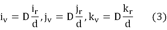
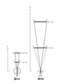
≪バーチャルな手の大きさの決定処理≫
図7Aおよび図7Bを用いてバーチャルな手の大きさの決定処理を説明する。実空間の原点O(つまり原点R[0,0,0])から距離dにある(つまり図7Aにおいて位置Pr2にある)リアルな手の大きさをSdとし、実空間の原点Oで当該原点Oから距離dにあるリアルな手のなす視角をθとし、視角θを二等分した視角をθhalf=θ/2とする。この場合、このリアルな手の大きさSdは以下の関係式を満たす。
Sd=2×d×tanθhalf (4)
ここで、VR空間において、原点OI(つまり原点V[0,0,0])から距離Dにある(つまり図7Bにおいて位置Pv2にある)バーチャルな手の視角が、実空間の原点Oで当該原点Oから距離dにあるリアルな手のなす視角θと同じになるようにするためには、バーチャルな手の大きさSDが以下の関係式を満たす必要がある。
SD=2×D×tanθhalf (5)
なお、図7BはD>dの場合を例示しているが、D≦dの場合であってもバーチャルな手の大きさSDが式(5)を満たす必要がある。以上より、原点OIから距離Dの位置にバーチャルな手を配置し、その視角をリアルな手のなす視角θと同一にするためには、式(5)を満たすバーチャルな手の大きさSDとすればよい。仮想サイズ計算部126は、上述した式(4)と式(5)を満たすバーチャルな手の大きさSDを得て出力する。例えば、仮想サイズ計算部126は、実空間位置取得装置11で得られた位置情報pr、実距離計算部122から出力された距離d、および仮想距離計算部123から出力された距離Dを入力とし、式(4)と式(5)を満たすバーチャルな手の大きさSDを得て出力する。一例を示すと、仮想サイズ計算部126は、位置情報prに基づいてtanθhalfを求め(例えば、前述のように位置情報prに基づいてSdを求め、Sdとdとを用いて式(4)に従ってtanθhalfを求め)、tanθhalfとDと用いて式(5)に従ってSDを求めて出力する。
≪Virtual hand size determination process≫
The virtual hand size determination process will be described with reference to FIGS. 7A and 7B. Let S d be the size of a real hand at a distance d (that is, at position Pr2 in FIG. 7A) from the origin O in the real space (that is, the origin R [0,0,0]), and at the origin O in the real space. Let θ be the viewing angle formed by a real hand at a distance d from the origin O, and let θ half = θ / 2 be the viewing angle obtained by dividing the viewing angle θ into two equal parts. In this case, this realistic hand size S d satisfies the following relational expression.
S d = 2 × d × tan θ half (4)
Here, in the VR space, the viewing angle of the virtual hand at the distance D from the origin O I (that is, the origin V [0, 0, 0]) (that is, at the position P v2 in FIG. 7B) is the origin O in the real space. In order to make it the same as the viewing angle θ formed by a real hand at a distance d from the origin O, the virtual hand size S D needs to satisfy the following relational expression.
SD = 2 × D × tan θ half (5)
Although FIG. 7B illustrates the case of D> d, it is necessary that the virtual hand size S D satisfies the equation (5) even in the case of D ≦ d. From the above, in order to place a virtual hand at a position at a distance D from the origin OI and make the viewing angle the same as the viewing angle θ formed by the real hand, the size S of the virtual hand satisfying the equation (5). It may be D. The virtual
実空間画像取得装置10は、観察者のリアルな手の画像を表す画像情報grを取得して出力する。画像処理部127には、実空間画像取得装置10で得られた画像情報gr、仮想座標計算部124で得られた座標値iv,jv,kv、および、仮想サイズ計算部126で得られたバーチャルな手の大きさSDが入力される。画像処理部127は、VR空間において、画像情報grで特定されるリアルな手を模したバーチャルな手であって、座標値iv,jv,kvの位置V[iv,jv,kv]に配置され(例えば、位置V[iv,jv,kv]を中心点として配置され)、大きさがSDであるバーチャルな手を含む画像pvを生成して出力する。リアルな手を模したバーチャルな手とは、例えば、リアルな手と相似または略相似なバーチャルな手を意味する。バーチャルな手の色彩は、例えば、リアルな手の色彩と同一である。
The real space
≪提示用画像の生成および提示≫
画像処理部127から出力された画像pvは提示用画像生成部128に入力される。提示用画像生成部128は、画像pvを用い、VR空間においてカメラの位置(例えば、原点OIや結像面I)から見えるバーチャルな手(リアルな手を拡大または縮小したものに対応するバーチャルな手であって、位置V[iv,jv,kv]に配置され、大きさがSDであるバーチャルな手)を観察者に提示するための提示用画像Pを生成して出力する。提示用画像Pは、静止画像であってもよいし、動画像(動画)であってもよい。提示用画像Pの一例は、規定のフレームレート(例えば30Hz)の動画像である。提示用画像Pは、例えば、観察者の右眼と左眼にそれぞれ提示する右眼用画像と左眼用画像とを有する。この例の場合、提示用画像生成部128は、右眼用画像と左眼用画像とを取得するために、画像pvが表示されたVR空間に2つのカメラをそれらの撮影方向が平行に同方向を向くように設置し、これらのカメラでVR空間を撮影する撮影シミュレーションを行う。この撮影シミュレーションでは、例えば、これら2つのカメラの各結像面Iが同一直線上に配置され、カメラ間の水平距離を人間の眼間距離(約6.5cm)またはその近傍に合わせる。左側に配置されたカメラで撮影した画像を左眼用画像とし、右側に配置されたカメラで撮影した画像を右眼用画像とする。撮影シミュレーションには、上述した3Dモデリング/レンダリングソフトウェアなどの周知の技術を用いればよい。
≪Generation and presentation of images for presentation≫
The image pv output from the
画像提示装置13は、提示用画像Pを入力とし、提示用画像Pを観察者に提示する。例えば、画像提示装置13がヘッドマウントディスプレイであり、提示用画像Pが右眼用画像と左眼用画像とを有する場合、ヘッドマウントディスプレイの右眼用ディスプレイが右眼用画像を提示し、左眼用ディスプレイが左眼用画像を提示する。これにより、ヘッドマウントディスプレイを装着した観察者の右眼には右眼用画像が提示され、左眼には左眼用画像が提示される。提示用画像Pが提示された観察者はVR空間でバーチャルな手を認知する。
The
ヘッドマウントディスプレイが提示する右眼用画像と左眼用画像におけるバーチャルな手のなす視角は、前述したパラメータαの値にかかわらず、リアルな手のなす視角と同一である。しかしながら、前述したパラメータαがα>1であるとき、大きさ恒常性の働きにより、観察者はバーチャルな手がバーチャルな巨人の手であると認知する。0<α<1であるとき、大きさ恒常性の働きにより、観察者はバーチャルな手がバーチャルな小人の手であると認知する。α=1であるとき、大きさ恒常性の働きにより、観察者はバーチャルな手がバーチャルな普通の手であると認知する。ここで、再掲するが、ヘッドマウントディスプレイが提示する右眼用画像と左眼用画像におけるバーチャルな手のなす視角は、αの値にかかわらず、リアルな手のなす視角と同一である。そのため、ヘッドマウントディスプレイが提示する右眼用画像と左眼用画像におけるバーチャルな巨人の手、バーチャルな小人の手、およびバーチャルな普通の手の見かけの質感は、αの値にかかわらず、リアルな手の見かけの質感と大きく異ならない。すなわち、α>1のときにバーチャルな巨人の手の表面形状が粗くなり過ぎたり、0<α<1のときにバーチャルな小人の手の表面形状がきめ細かくなり過ぎたりしない。また、バーチャルな巨人の手がヘッドマウントディスプレイに表示される空間範囲からはみ出してしまうこともない。 The viewing angle of the virtual hand in the image for the right eye and the image for the left eye presented by the head-mounted display is the same as the viewing angle of the real hand regardless of the value of the parameter α described above. However, when the above-mentioned parameter α is α> 1, the observer recognizes that the virtual hand is the virtual giant's hand due to the action of size homeostasis. When 0 <α <1, the observer recognizes that the virtual hand is the virtual dwarf's hand due to the action of size homeostasis. When α = 1, the observer recognizes that the virtual hand is a virtual ordinary hand due to the action of size homeostasis. Here, again, the viewing angle of the virtual hand in the image for the right eye and the image for the left eye presented by the head-mounted display is the same as the viewing angle of the real hand regardless of the value of α. Therefore, the apparent texture of the virtual giant's hand, the virtual dwarf's hand, and the virtual ordinary hand in the right-eye image and the left-eye image presented by the head-mounted display is not related to the value of α. It is not much different from the realistic texture of the hand. That is, when α> 1, the surface shape of the virtual giant's hand does not become too rough, and when 0 <α <1, the surface shape of the virtual dwarf's hand does not become too fine. Also, the virtual giant's hand does not go beyond the space shown on the head-mounted display.
[第1実施形態の変形例]
第1実施形態では、仮想サイズ計算部126が式(5)に従ってSDを求めて出力した。上述した、式(4)と式(5)を満たすことは、下記の式(6A)や式(6B)を満たすことと等価である。
SD/Sd=D/d (6A)
SD=Sd×D/d (6B)
また、式(2)から分かる通りD/d=αであるので、式(6A)と式(6B)は下記の式(6C)と式(6D)と等価である。
SD/Sd=α (6C)
SD=Sd×α (6D)
したがって、第1実施形態では仮想サイズ計算部126が式(4)と式(5)に従ってSDを求めて出力したが、仮想サイズ計算部126がSdをD/d倍した値をSDとして出力してもよいし、仮想サイズ計算部126がSdをα倍した値をSDとして出力してもよい。例えば、仮想サイズ計算部126が、入力された位置情報prに基づいてSdを求め、求めたSdと入力されたαと乗算したものをSDとして出力してもよい。あるいは、仮想サイズ計算部126が、入力された位置情報prに基づいてSdを求め、求めたSdと入力されたDおよびdを用いて式(6B)によってSDを計算して出力してもよい。
[Modified example of the first embodiment]
In the first embodiment, the virtual
S D / S d = D / d (6A)
S D = S d x D / d (6B)
Further, as can be seen from the equation (2), since D / d = α, the equations (6A) and (6B) are equivalent to the following equations (6C) and (6D).
S D / S d = α (6C)
S D = S d x α (6D)
Therefore, in the first embodiment, the virtual
[第2実施形態]
バーチャルリアリティを実現するソフトウェアでは、VR空間内の対象のモデルの大きさを、基準となる対象の大きさに対する比率で設定することができる。このようなソフトウェアを用いてバーチャルな手の大きさをリアルな手の大きさのα倍にしてもよい。ただし、このような既存のソフトウェアは、対象の視角を保ちつつ、対象のモデルの大きさを変更するものではない。第2実施形態ではこのようなソフトウェア(「VRソフトウェア」と呼ぶことにする)の機能を用いる。以降、これまで説明した事項との相違点を中心に説明し、既に説明した事項については同じ参照番号を引用して説明を簡略化する。
[Second Embodiment]
In software that realizes virtual reality, the size of the target model in VR space can be set as a ratio to the size of the reference target. Such software may be used to make the size of a virtual hand α times the size of a real hand. However, such existing software does not change the size of the target model while maintaining the target viewing angle. In the second embodiment, the function of such software (referred to as "VR software") is used. Hereinafter, the differences from the items described so far will be mainly explained, and the same reference numbers will be cited for the items already explained to simplify the explanation.
<構成>
図8に例示するように、本実施形態の画像処理システム2は、実空間画像取得装置10、実空間位置取得装置11、画像処理装置22、および画像提示装置13を有する。画像処理装置22は、実座標計算部121、仮想座標計算部224、画像処理部227、および提示用画像生成部128を有する装置である。実座標計算部121、仮想座標計算部224、および画像処理部227が、リアルな手を拡大または縮小したバーチャルな手を生成する処理部(視対象生成部)である。
<Structure>
As illustrated in FIG. 8, the
<処理>
本実施形態の処理を説明する。
≪リアルな手の位置の計測≫
第1実施形態と同じである。すなわち、実空間位置取得装置11は、実空間における観察者のリアルな手の位置を表す位置情報prを取得して出力する。実座標計算部121は、この位置情報prを入力とし、観察者のリアルな手の位置R[ir,jr,kr]を表す座標値ir,jr,krを得て出力する。
<Processing>
The processing of this embodiment will be described.
≪Realistic hand position measurement≫
It is the same as the first embodiment. That is, the real space
≪バーチャルな手の位置を決定する処理≫
α=D/dであるため、式(3)は以下の式(7)に変形できる。
![]()
仮想座標計算部224は、実座標計算部121で得られた位置R[ir,jr,kr]の座標値ir,jr,krおよび入力されたパラメータαを入力とし、式(7)に従って、バーチャルな手の位置V[iv,jv,kv]の座標値iv,jv,kvを得て出力する。バーチャルな手の位置V[iv,jv,kv]の例は、バーチャルな手の3次元的な中心点である。
≪Process to determine the position of the virtual hand≫
Since α = D / d, the equation (3) can be transformed into the following equation (7).
![]()
The virtual coordinate
≪バーチャルな手の大きさの決定処理≫
実空間画像取得装置10は、観察者のリアルな手の画像を表す画像情報grを取得して出力する。画像処理部227には、入力されたパラメータα、実空間画像取得装置10で得られた画像情報gr、および仮想座標計算部224で得られた座標値iv,jv,kvが入力される。画像処理部227は、VR空間において、画像情報grで特定されるリアルな手を模したバーチャルな普通の手を拡大または縮小したバーチャルな手であって、座標値iv,jv,kvの位置V[iv,jv,kv]に配置され(例えば、位置V[iv,jv,kv]を中心点とし)、大きさがバーチャルな普通の手のα倍であるバーチャルな手を含む画像pvを生成して出力する。ここで、大きさがバーチャルな普通の手のα倍であるバーチャルな手を生成するためには、前述したVRソフトウェアにおいてαを指定すればよい。リアルな手の大きさをDdとすると、このように生成されるバーチャルな手の大きさSDも式(6)の関係を満たす。
≪Virtual hand size determination process≫
The real space
≪提示用画像の生成および提示≫
第1実施形態と同じである。
≪Generation and presentation of images for presentation≫
It is the same as the first embodiment.
[第3実施形態]
第1実施形態、第1実施形態の変形例、および第2実施形態において、パラメータαの値を変化させてもよい。これにより、バーチャルな手の質感を大きく変化させることなく、バーチャルな手の見かけの大きさを変化させることができる。図9に、VR空間において、実空間の原点Oでリアルな手のなす視角がθである場合にパラメータαを変化させ、バーチャルな手の奥行き距離kvを変化させた様子を例示する。ここで、α=1の場合のバーチャルな手の奥行き距離kvをDα=1とし、α=δの場合のバーチャルな手の奥行き距離kvをDα=δとし、α=λの場合のバーチャルな手の奥行き距離kvをDα=λとする。ただし、0<λ<1<δである。原点OIから距離Dα=1にある(つまり図9において位置Pα=1にある)バーチャルな手の大きさをSDα=1とし、原点OIから距離Dα=δにある(つまり図9において位置Pα=δにある)バーチャルな手の大きさをSDα=δとし、原点OIから距離Dα=λにある(つまり図9において位置Pα=λにある)バーチャルな手の大きさをSDα=λとする。ここで、SD=SDα=1とし、D=Dα=1とすると、前述の式(5)の関係を満たす。同様に、SD=SDα=δとし、D=Dα=δとすると、前述の式(5)の関係を満たし、SD=SDα=λとし、D=Dα=λとすると、前述の式(5)の関係を満たす。図9に例示するように、αの値を増加させることにより、視角θを保ったままバーチャルな手の奥行き距離および大きさが共に大きくなる。具体的には、αの値がδ倍になると、視角θを保ったままバーチャルな手の奥行き距離kvおよび大きさも共にδ倍になる。逆に、αの値を減少させることにより、視角θを保ったままバーチャルな手の奥行き距離kvおよび大きさが共に小さくなる。具体的には、αの値がλ倍になると、視角θを保ったままバーチャルな手の奥行き距離kvおよび大きさも共にλ倍になる。これにより、バーチャルな手の質感を大きく変化させることなく、バーチャルな手の見かけの大きさを変化させることができる。例えば、α=1をα=δに変更することで、バーチャルな手の質感を大きく変化させることなく、バーチャルな普通の手をバーチャルな巨人の手に変更することができる。また、α=1をα=λに変更することで、バーチャルな手の質感を大きく変化させることなく、バーチャルな普通の手をバーチャルな小人の手に変更することができる。あるいは、α=δまたはα=λをα=1に変更することで、バーチャルな手の質感を大きく変化させることなく、バーチャルな巨人の手やバーチャルな小人の手をバーチャルな普通の手に変更することができる。
[Third Embodiment]
In the first embodiment, the modification of the first embodiment, and the second embodiment, the value of the parameter α may be changed. This makes it possible to change the apparent size of the virtual hand without significantly changing the texture of the virtual hand. FIG. 9 illustrates a state in which the parameter α is changed and the virtual hand depth distance kv is changed when the viewing angle formed by the real hand at the origin O in the real space is θ in the VR space. Here, the virtual hand depth distance k v when α = 1 is D α = 1 , the virtual hand depth distance k v when α = δ is D α = δ , and α = λ. Let D α = λ be the virtual hand depth distance k v of. However, 0 <λ <1 <δ. The size of the virtual hand at the distance D α = 1 from the origin O I (that is, at the position P α = 1 in FIG. 9) is S D α = 1 , and the distance D α = δ from the origin O I (that is,). The virtual hand size (at position P α = δ in FIG. 9) is SD α = δ , and the distance D α = λ from the origin O I (that is, at position P α = λ in FIG. 9) is virtual. Let the size of the hand be SDα = λ . Here, if S D = S D α = 1 and D = D α = 1 , the relationship of the above equation (5) is satisfied. Similarly, if S D = S D α = δ and D = D α = δ , the relationship of the above equation (5) is satisfied, and if S D = S D α = λ and D = D α = λ , then The relationship of the above equation (5) is satisfied. As illustrated in FIG. 9, by increasing the value of α, both the depth distance and the size of the virtual hand are increased while maintaining the viewing angle θ. Specifically, when the value of α is multiplied by δ, the depth distance kv and the size of the virtual hand are both multiplied by δ while maintaining the viewing angle θ. On the contrary, by reducing the value of α, both the depth distance kv and the size of the virtual hand are reduced while maintaining the viewing angle θ. Specifically, when the value of α is multiplied by λ, the depth distance kv and the size of the virtual hand are both multiplied by λ while maintaining the viewing angle θ. This makes it possible to change the apparent size of the virtual hand without significantly changing the texture of the virtual hand. For example, by changing α = 1 to α = δ, it is possible to change a virtual ordinary hand into a virtual giant's hand without significantly changing the texture of the virtual hand. Further, by changing α = 1 to α = λ, it is possible to change a virtual ordinary hand into a virtual dwarf's hand without significantly changing the texture of the virtual hand. Alternatively, by changing α = δ or α = λ to α = 1, the virtual giant's hand or virtual dwarf's hand becomes a virtual ordinary hand without significantly changing the texture of the virtual hand. Can be changed.
なお、画像処理装置に入力されるパラメータαの値を変化させてもよいし(変化態様1)、画像処理装置に入力または記憶されたパラメータαの値に何等かの演算を施してパラメータαの値を変化させてもよい(変化態様2)。変化態様1の一例は、パーソナルコンピュータ等のキーボードの左矢印キーと右矢印キーをインターフェースとし、左矢印キーを押すとαが小さくなり、右矢印キーを押すとαが大きくなるように設定するものである。例えば、α≧1を満たすパラメータαに対応するバーチャルな手をバーチャルな小人の手にしようとする場合には、観察者は左矢印キーを押してαを0<α<1を満たす値に設定する。例えば、0<α≦1を満たすパラメータαに対応するバーチャルな手をバーチャルな巨人の手にしようとする場合には、観察者が右矢印キーを押してαをα>1を満たす値に設定する。α≠1を満たすパラメータαに対応するバーチャルな手をバーチャルな普通の手にしようとする場合には、右矢印キーまたは左矢印キーを押してαをα=1に設定する。実際に用いるキーは左右矢印キーでなくとも任意の2つのキーでよい。その他、例えば、マウスを用いた入力、スマートフォン端末装置などのタッチパネルへの入力、ゲームコントローラーによる入力、音声入力、非接触入力デバイスによる入力などによってパラメータαの値を変更してもよい。変化態様2としては、例えば、αの大きさが、時間経過に伴って単調増加または単調減少したり、時間経過に伴って周期的に変動したり、ランダムに変化したり、不連続に変化したり、別の処理結果に応じて変化したりする態様を例示できる。
The value of the parameter α input to the image processing device may be changed (change mode 1), or the value of the parameter α input or stored in the image processing device may be subjected to some calculation to obtain the parameter α. The value may be changed (change mode 2). One example of the
その他、パラメータαがリアルな手の奥行き距離krに応じた値であってもよい。例えば、画像処理装置は、リアルな手の奥行き距離krが所定の奥行き距離(所定距離)κ1(ただし、κ1は正値)であるときにパラメータαの値をα1(ただし、α1は正値)とし、リアルな手の奥行き距離krがκ2(ただし、κ2はκ1と異なる正値)あるときにパラメータαの値をα2(ただし、α2はα1と異なる正値)としてもよい。例えば、リアルな手の奥行き距離krの関数値FNC(kr)をαとしてもよい。すなわちα=FNC(kr)としてもよい。この例において、FNC(kr)は、リアルな手の奥行き距離krが所定距離κ1であるときにα=1となるものであってもよいし、0≦kr≦κ1であるときにα=1となるものであってもよい。また例えば、FNC(kr)は、kr=κ21とkr=κ22>κ21とに対し、FNC(κ22)>FNC(κ21)を満たすものであるとよい。この例では、κ1に対するkr=κ22の上回り分がκ22-κ1であるときのFNC(κ22)が、κ1に対するkr=κ21の上回り分がκ21-κ1であるときのFNC(κ21)よりも大きくなる。κ22>κ21であるため、上回り分κ22-κ1は上回り分κ21-κ1よりも大きい。例えば、FNC(kr)は、κ1<krの範囲において、krの増加に対して単調増加するものであってもよいし、krの増加に対して非減少(広義単調増加)するものであってもよい。また、FNC(kr)は、連続関数とするとよく、krの増加に対して単調増加する連続関数であることが好ましい。例えば、リアルな手の奥行き距離krの最大値(例えばリアルな手が届く最大距離(例えば、1m))をκmax>κ1とし、kr=κmaxのときの関数値をFNC(κmax)=α0(ただし、α0>1)とし、FNC(κ1)=1とFNC(κmax)=α0との間をkrについて線形補完した値をFNC(kr)(ただし、κ1<kr≦κmax)としてもよい。このようなFNC(kr)を式(8)に例示する。
FNC(kr)=1+(α0-1)×(kr-κ1)/(κmax-κ1) (8)
例えば、0≦kr≦κ1であるときにα=1とされ、κ1<κ2=krであるときにα=FNC(κ2)とされ、かつ、FNC(κ2)がκ2の増加に対して単調増加する例の場合、バーチャルな手は以下のように見える。すなわち、リアルな手の奥行き距離krがκ1以下(例えば目から30cm以下)であるときには、バーチャルな手が、リアルな手と同じ奥行き(例えば目から30cm)に、リアルな手と同じ大きさで見える(α=1)。一方、リアルな手の奥行き距離krがκ1を超えるときには、リアルな手が目から遠ざかるにつれて、バーチャルな手はリアルな手より遠くに、リアルな手より大きく見える(krが大きくなるにつれてαがだんだん大きくなる)。
In addition, the parameter α may be a value corresponding to the real depth distance kr of the hand. For example, the image processing device sets the value of the parameter α to α 1 (where α) when the real hand depth distance k r is a predetermined depth distance (predetermined distance) κ 1 (where κ 1 is a positive value). 1 is a positive value), and when the real hand depth distance k r is κ 2 (where κ 2 is a positive value different from κ 1 ), the value of the parameter α is α 2 (where α 2 is α 1 ). It may be a different positive value). For example, the function value FNC ( kr ) of the real hand depth distance kr may be α. That is, α = FNC ( kr ) may be set. In this example, the FNC ( kr ) may be α = 1 when the real hand depth distance kr is a predetermined distance κ 1 , or 0 ≦ kr ≦ κ 1 . Sometimes α = 1 may be set. Further, for example, FNC ( kr ) may satisfy FNC (κ 22 )> FNC (κ 21 ) for kr = κ 21 and kr = κ 22 > κ 21 . In this example, FNC (κ 22 ) when the excess of kr = κ 22 for κ 1 is κ 21 −κ 1 and the excess of kr = κ 21 for κ 1 is κ 21 −κ 1 . It is larger than FNC (κ 21 ) at one time. Since κ 22 > κ 21 , the excess κ 22 -κ 1 is larger than the excess κ 21 -κ 1 . For example, FNC ( kr ) may be monotonically increasing with increasing kr in the range of κ 1 < kr , or non-decreasing with increasing kr (broadly monotonically increasing). It may be something to do. Further, FNC ( kr ) may be a continuous function, and is preferably a continuous function that increases monotonically with an increase in kr . For example, the maximum value of the depth distance kr of a real hand (for example, the maximum distance that a real hand can reach (for example, 1 m)) is κ max > κ 1 , and the function value when kr = κ max is FNC (κ). max ) = α 0 (where α 0 > 1), and the value linearly complemented for kr between FNC (κ 1 ) = 1 and FNC (κ max ) = α 0 is FNC ( kr ) (provided that). , Κ 1 < kr ≤ κ max ). Such FNC ( kr ) is illustrated in the equation (8).
FNC (kr) = 1 + (α 0-1 ) × (kr −κ 1 ) / (κ max −κ 1 ) (8)
For example, when 0 ≤ k r ≤ κ 1 , α = 1, and when κ 1 <κ 2 = k r , α = FNC (κ 2 ), and FNC (κ 2 ) is κ. In the case of an example of monotonically increasing with respect to an increase of 2 , the virtual hand looks like this: That is, when the depth distance kr of the real hand is κ 1 or less (for example, 30 cm or less from the eyes), the virtual hand has the same depth as the real hand (for example, 30 cm from the eyes) and the same size as the real hand. It can be seen by the hand (α = 1). On the other hand, when the depth distance kr of the real hand exceeds κ 1 , the virtual hand looks farther than the real hand and larger than the real hand as the real hand moves away from the eye (as kr increases). α gets bigger and bigger).
[その他の変形例]
なお、本発明は上述の実施形態およびその変形例に限定されるものではない。例えば、上述の実施形態およびその変形例では、実空間における原点Oからリアルな手の3次元形状の中心点までの距離をdとし、VR空間におけるカメラの原点OIからバーチャルな手の3次元形状の中心点までの距離をDとする例を示した。しかしながら、原点Oからリアルな手の3次元形状の他の任意の一点までの距離をdとしてもよいし、原点OIからバーチャルな手の3次元形状の他の任意の一点までの距離をDとしてもよい。その他、原点Oからリアルな手の3次元形状の各点までの距離に基づいて、原点OIからバーチャルな手の3次元形状の各点の距離を定めてよい。また、上述の実施形態およびその変形例では、目の水晶体内部に位置する点を原点Oとする例を示したが、目の他の位置または目の近傍の位置を原点Oとしてもよい。また、上述の実施形態およびその変形例では、目の原点Oを原点R[0,0,0]とする例を説明したが、目の原点Oの近傍を原点R[0,0,0]としてもよいし、目の原点Oに対する相対位置が固定されたその他の点を原点R[0,0,0]としてもよい。同様に、上述の実施形態およびその変形例では、VR空間のカメラの結像面Iの焦点を原点OIとする例を示したが、カメラの結像面Iの他の位置または結像面Iの近傍の位置を原点OIとしてもよい。また、上述の実施形態およびその変形例では、原点OIを原点V[0,0,0]とする例を示したが、原点OIの近傍を原点V[0,0,0]としてもよいし、原点OIに対する相対位置が固定されたその他の点を原点V[0,0,0]としてもよい。また、上述の実施形態およびその変形例では、画像処理部127が、位置V[iv,jv,kv]を中心点とするバーチャルな手を含む画像pvを生成する例を示した。しかし、位置V[iv,jv,kv]をバーチャルな手の他の位置としてもよいし、位置V[iv,jv,kv]をバーチャルな手に対する相対位置としてもよい。また、上述の実施形態およびその変形例では、便宜上、手右手親指の先端から右手小指の付け根までの距離を基準距離とした。しかし、手の他の部位の距離を基準距離としてもよい。
[Other variants]
The present invention is not limited to the above-described embodiment and its modifications. For example, in the above-described embodiment and its modification, the distance from the origin O in the real space to the center point of the three-dimensional shape of the real hand is d, and the three-dimensional shape of the virtual hand is taken from the origin OI of the camera in the VR space. An example is shown in which the distance to the center point of the shape is D. However, the distance from the origin O to any other point in the 3D shape of the real hand may be d, and the distance from the origin OI to any other point in the 3D shape of the virtual hand may be D. May be. In addition, the distance from the origin OI to each point of the virtual hand 3D shape may be determined based on the distance from the origin O to each point of the real hand 3D shape. Further, in the above-described embodiment and its modification, an example in which a point located inside the crystalline lens of the eye is set as the origin O is shown, but another position of the eye or a position near the eye may be set as the origin O. Further, in the above-described embodiment and its modification, an example in which the origin O of the eye is the origin R [0,0,0] has been described, but the vicinity of the origin O of the eye is the origin R [0,0,0]. Alternatively, the origin R [0, 0, 0] may be set as another point whose relative position with respect to the origin O of the eye is fixed. Similarly, in the above-described embodiment and its modification, an example is shown in which the focal point of the image plane I of the camera in VR space is the origin OI, but another position or the image plane of the image plane I of the camera is shown. The position near I may be the origin OI. Further, in the above-described embodiment and its modification, an example in which the origin O I is set to the origin V [0, 0, 0] is shown, but the vicinity of the origin O I may be set to the origin V [0, 0, 0]. Alternatively, the other point whose relative position to the origin OI is fixed may be the origin V [0,0,0]. Further, in the above-described embodiment and its modification, an example is shown in which the
上述の実施形態およびその変形例ではパラメータαが正の実数変数であったが、パラメータαが正の実数定数であってもよい。すなわち、定数であるパラメータαが画像処理装置に予め設定され、画像処理装置がこのパラメータαを用いて前述の処理を行ってもよい。 In the above-described embodiment and its modification, the parameter α is a positive real number variable, but the parameter α may be a positive real number constant. That is, a parameter α, which is a constant, may be set in advance in the image processing device, and the image processing device may perform the above-mentioned processing using this parameter α.
上述の実施形態およびその変形例では、観察者(ヒト)のリアルな手を模したバーチャルな手のモデルをVR空間に配置した。しかし、このようなバーチャルな手のモデルに代えて任意の3D形状モデル(ポリゴンの集合体)をVR空間内に配置してもよい。すなわち、上述の実施形態およびその変形例において、「バーチャルな手」がVR空間における任意の3D形状物(「バーチャルな3D形状物」と呼ぶ)に置換され、「バーチャルな普通の手」が「バーチャルな普通の3D形状物」に置換され、「バーチャルな巨人の手」が「バーチャルな巨大3D形状物」に置換され、「バーチャルな小人の手」が「バーチャルな極小3D形状物」に置換され、前述の処理が実行されてもよい。ただし、「バーチャルな普通の3D形状物」とは、観察者がリアルな手と同じ見かけの大きさを持つと知覚するバーチャルな3D形状物を意味する。「バーチャルな巨大3D形状物」とは、観察者がリアルな手よりも大きいと知覚するバーチャルな3D形状物を意味する。「バーチャルな極小3D形状物」とは、観察者がリアルな手よりも小さいと知覚するバーチャルな3D形状物を意味する。「観察者がリアルな手と同じ見かけの大きさを持つと知覚する」とは、例えば、観察者がリアルな手の基準部の基準距離とバーチャルな3D形状物の線形寸法とが同じであると知覚することを意味する。「観察者がリアルな手よりも大きいと知覚する」とは、例えば、観察者がリアルな手の基準部の基準距離よりもバーチャルな3D形状物の線形寸法の方が大きいと知覚することを意味する。「観察者がリアルな手よりも小さいと知覚する」とは、例えば、観察者がリアルな手の基準部の基準距離よりもバーチャルな3D形状物の線形寸法の方が小さいと知覚することを意味する。「3D形状物の線形寸法」はどのように定義されてもよい。「3D形状物の線形寸法」の例は、3D形状物の特定の部位の外形寸法、3D形状物の外形寸法の最大値、3D形状物の外形寸法の最小値、3D形状物の外形寸法の平均値などである。バーチャルな手のモデルに代えて任意の3D形状モデルをVR空間内に配置する場合、実空間画像取得装置10が省略され、画像処理部127,227には画像情報grに代えて任意の3D形状モデルが入力される。この場合、画像処理部127,227は、画像情報grに代えて当該任意の3D形状モデルを用いて画像pvを生成して出力する。任意の3D形状モデルは、画像処理装置の外部から入力されたものであってもよいし、画像処理装置の記憶部(図示せず)から読み出されたものであってもよい。これにより、観察者に対し、リアルな手の動きに応じてVR空間内を移動するバーチャルな3D形状物を提示することができ、このバーチャルな3D形状物の質感を大きく異ならせずに、パラメータαの値に応じてバーチャルな3D形状物を大きく見せたり、小さく見せたりすることもできる。例えば、パラメータαの値をα>1とすることで、リアルな手の動きに応じてVR空間内を移動するバーチャルな巨大3D形状物を提示できる。パラメータαの値を0<α≦1とすることで、リアルな手の動きに応じてVR空間内を移動するバーチャルな極小3D形状物を提示できる。また、パラメータαの値をα=1とすることで、リアルな手の動きに応じてVR空間内を移動するバーチャルな普通の3D形状物を提示できる。また、パラメータαを変更することで、観察者が知覚する見かけの質感を大きく異ならせることなく、リアルな手の動きに応じてVR空間内を移動するバーチャルな3D形状物を大きく見せたり小さく見せたりすることができる。また、「バーチャルな3D形状物」は、実空間における任意の視対象を模したものであってもなくてもよいし、実空間に存在する視対象を表したものであってもなくてもよい。「バーチャルな3D形状物」の例は、ロボットアームを表したポリゴンの集合体、ハンマーやトングといった手で操作される道具を表したポリゴンの集合体などである。また、通常はリアルな手の動きに連動しないものを表したポリゴンの集合体を「バーチャルな3D形状物」としてもよい。例えば、トラを表したポリゴンの集合体を「バーチャルな3D形状物」としてもよい。
In the above-described embodiment and its modification, a virtual hand model imitating the real hand of the observer (human) is placed in the VR space. However, instead of such a virtual hand model, an arbitrary 3D shape model (aggregate of polygons) may be arranged in the VR space. That is, in the above-described embodiment and its modifications, the "virtual hand" is replaced with an arbitrary 3D shape object (referred to as "virtual 3D shape object") in the VR space, and the "virtual ordinary hand" is replaced with "virtual ordinary hand". "Virtual ordinary 3D shape" is replaced, "Virtual giant's hand" is replaced with "Virtual giant 3D shape", "Virtual dwarf's hand" is replaced with "Virtual tiny 3D shape" It may be replaced and the above-mentioned processing may be executed. However, the "virtual ordinary 3D object" means a virtual 3D object that the observer perceives as having the same apparent size as a real hand. The "virtual giant 3D object" means a virtual 3D object that the observer perceives to be larger than a real hand. The "virtual micro 3D object" means a virtual 3D object that the observer perceives to be smaller than a real hand. "The observer perceives that it has the same apparent size as a real hand" means, for example, that the observer has the same reference distance to the reference part of the real hand and the linear dimensions of the virtual 3D shape. It means to perceive. "The observer perceives that it is larger than the real hand" means, for example, that the observer perceives that the linear dimension of the virtual 3D shape is larger than the reference distance of the reference part of the real hand. means. "The observer perceives that it is smaller than the real hand" means, for example, that the observer perceives that the linear dimension of the virtual 3D shape is smaller than the reference distance of the reference part of the real hand. means. "Linear dimensions of 3D shaped objects" may be defined in any way. An example of "linear dimensions of a 3D shape" is the external dimensions of a specific part of a 3D shape, the maximum value of the external dimensions of a 3D shape, the minimum value of the external dimensions of a 3D shape, and the external dimensions of a 3D shape. For example, the average value. When arranging an arbitrary 3D shape model in the VR space instead of the virtual hand model, the real space
上述の実施形態およびその変形例では、実空間のリアルな手の位置R[ir,jr,kr]の座標値ir,jr,krおよびパラメータαに基づいて、VR空間のバーチャルな手の位置V[iv,jv,kv]の座標値iv,jv,kvおよびバーチャルな手の大きさSDを求める例を示した。しかしながら、距離dと視角θとの典型的な関係が予め推定可能であるならば、リアルな手の位置に基づかずとも、パラメータαのみからバーチャルな3D形状物の位置およびバーチャルな3D形状物の大きさを求めることができる。例えば、観察者から特定の距離(特定距離)d(例えば、d=1)の位置にある視対象のなす視角θを推定可能なのであれば、VR空間において、この推定した視角(推定視角)θをなし、パラメータαに応じた大きさSDを持つバーチャルな3D形状物を提示することが可能である。バーチャルな3D形状物の大きさSDは、例えば、前述した「3D形状物の線形寸法」である。さらに、パラメータαの値を変化させることで、バーチャルな3D形状物の見かけの質感を大きく変えることなく、バーチャルな3D形状物を大きく見せたり、小さく見せたりすることができる。例えば、画像処理装置は、原点Oから特定距離dに存在する視対象のなす視角を推定できれば、推定した視角(推定視角)θを二等分した視角をθhalfとし、特定距離dとθhalfを用い、式(4)に基づいてSdを求めることができる。さらに、画像処理装置は、パラメータαと特定距離dとを用い、式(2)に基づいて距離Dを求めることができる。さらに、画像処理装置は、上述の推定視角θを二等分した視角θhalfと距離Dとを用い、式(5)に従ってSDを計算できる。画像処理装置は、このように得られた距離Dおよび大きさSDを用い、VR空間においてカメラの原点OIからの距離がDであり、大きさがSDである3D形状物を含む画像pvを生成できる。前述のように、このように得られる3D形状物のなす視角は常に推定視角θと同一になる。例えば、消しゴムの大きさはそれほど個体差がないので、消しゴムの典型的な大きさから、観察者から任意の特定距離dだけ離れた位置に存在する消しゴムのなす推定視角θを推定できる。そのため、消しゴムを表したポリゴンの集合体を3D形状物とした場合、画像処理装置は、実空間での消しゴムの位置に基づかずとも、VR空間において、原点OIで推定視角θをなし、パラメータαに対応する大きさSDを持つ消しゴムを表したポリゴンの集合体を含む画像pvを生成できる。 In the above embodiment and its variants, the VR space is based on the coordinate values ir , jr , kr and parameter α of the real hand position R [ir, jr , kr ] in real space. An example is shown in which the coordinate values iv , j v , k v of the virtual hand position V [ iv , j v , k v ] and the virtual hand size SD are obtained. However, if the typical relationship between the distance d and the viewing angle θ can be estimated in advance, the position of the virtual 3D shape and the virtual 3D shape can be obtained only from the parameter α, even if it is not based on the real hand position. The size can be calculated. For example, if it is possible to estimate the viewing angle θ formed by the visual object at a position of a specific distance (specific distance) d (for example, d = 1) from the observer, this estimated viewing angle (estimated viewing angle) θ in the VR space. It is possible to present a virtual 3D shaped object having a size SD corresponding to the parameter α. The size SD of the virtual 3D shape is, for example, the above-mentioned “linear dimension of the 3D shape”. Further, by changing the value of the parameter α, the virtual 3D shape can be made to look larger or smaller without significantly changing the apparent texture of the virtual 3D shape. For example, if the image processing device can estimate the visual angle formed by the visual object existing at the specific distance d from the origin O, the visual angle obtained by bisecting the estimated visual angle (estimated visual angle) θ is defined as θ half , and the specific distance d and θ half . Can be used to obtain S d based on the equation (4). Further, the image processing apparatus can obtain the distance D based on the equation (2) by using the parameter α and the specific distance d. Further, the image processing apparatus can calculate SD according to the equation (5) by using the viewing angle θ half obtained by bisecting the above-mentioned estimated viewing angle θ and the distance D. The image processing device uses the distance D and the size SD obtained in this way, and an image including a 3D object having a distance D from the origin OI of the camera in VR space and a size SD . p v can be generated. As described above, the viewing angle formed by the 3D shaped object thus obtained is always the same as the estimated viewing angle θ. For example, since the size of the eraser does not vary so much from individual to individual, the estimated viewing angle θ of the eraser existing at a position separated from the observer by an arbitrary specific distance d can be estimated from the typical size of the eraser. Therefore, when the aggregate of polygons representing the eraser is a 3D object, the image processing device makes an estimated viewing angle θ at the origin OI in the VR space, even if it is not based on the position of the eraser in the real space, and the parameter. It is possible to generate an image pv containing a collection of polygons representing an eraser having a size SD corresponding to α.
同様に、特定の視角(特定視角)θ(例えば、θ=10°)をなす視対象の距離dが推定可能なのであれば、リアルな手の位置に基づかずとも、パラメータαのみからVR空間のバーチャルな3D形状物の位置およびバーチャルな3D形状物の大きさを求めることができる。すなわち、観察者で特定視角θをなす視対象の距離(推定距離)dが推定可能なのであれば、VR空間において、原点OIでこの特定視角θをなし、パラメータαに応じた大きさSDを持つバーチャルな3D形状物を提示することが可能である。さらに、パラメータαの値を変化させることで、バーチャルな3D形状物の見かけの質感を大きく変えることなく、バーチャルな3D形状物を大きく見せたり、小さく見せたりすることができる。例えば、画像処理装置は、観察者で特定視角θをなす視対象の推定距離dを推定し、特定視角θを二等分した視角をθhalfとし、推定距離dとθhalfを用い、式(4)に基づいてSdを求めることができる。さらに、画像処理装置は、パラメータαと推定距離dとを用い、式(2)に基づいて距離Dを求めることができる。さらに、画像処理装置は、上述の視角θを二等分した視角θhalfと距離Dとを用い、式(5)に従ってSDを計算できる。画像処理装置は、このように得られた距離Dおよび大きさSDを用い、VR空間においてカメラの原点OIからの距離がDであり、大きさがSDである3D形状物を含む画像pvを生成できる。 Similarly, if the distance d of the visual object forming a specific viewing angle (specific viewing angle) θ (for example, θ = 10 °) can be estimated, the VR space can be obtained only from the parameter α without being based on the realistic hand position. The position of the virtual 3D object and the size of the virtual 3D object can be obtained. That is, if the observer can estimate the distance (estimated distance) d of the visual object forming the specific viewing angle θ, this specific viewing angle θ is formed at the origin OI in the VR space, and the size S D corresponding to the parameter α. It is possible to present a virtual 3D shaped object with. Further, by changing the value of the parameter α, the virtual 3D shape can be made to look larger or smaller without significantly changing the apparent texture of the virtual 3D shape. For example, the image processing device estimates the estimated distance d of the visual object forming the specific viewing angle θ by the observer, the viewing angle obtained by bisecting the specific viewing angle θ is set as θ half , and the estimated distance d and θ half are used in the equation ( S d can be obtained based on 4). Further, the image processing apparatus can obtain the distance D based on the equation (2) by using the parameter α and the estimated distance d. Further, the image processing apparatus can calculate SD according to the equation (5) by using the viewing angle θ half obtained by bisecting the above-mentioned viewing angle θ and the distance D. The image processing device uses the distance D and the size SD obtained in this way, and an image including a 3D object having a distance D from the origin OI of the camera in VR space and a size SD . p v can be generated.
また、上述の実施形態およびその変形例において、リアルな手が実空間のその他の視対象に置換されてもよい。例えば、リアルな手が、実空間の観察者の頭や足などのその他の部位、実空間のボールや自動車などの観察者以外の物、実空間で表示された画像等に置換されてもよい。 Further, in the above-described embodiment and its modifications, the real hand may be replaced with another visual object in the real space. For example, the realistic hand may be replaced with other parts such as the observer's head and feet in real space, non-observer objects such as balls and automobiles in real space, images displayed in real space, and the like. ..
また、バーチャルな手の色彩が、リアルな手の色彩に応じたその他の色彩であってもよいし、リアルな手の色彩と無相関な色彩であってもよい。 Further, the virtual hand color may be another color corresponding to the real hand color, or may be a color uncorrelated with the real hand color.
上述の各種の処理は、記載に従って時系列に実行されるのみならず、処理を実行する装置の処理能力あるいは必要に応じて並列的にあるいは個別に実行されてもよい。その他、本発明の範囲で適宜変更が可能であることはいうまでもない。 The various processes described above may not only be executed in chronological order according to the description, but may also be executed in parallel or individually as required by the processing capacity of the device that executes the processes. In addition, it goes without saying that changes can be made as appropriate within the scope of the present invention.
[まとめ]
上述した各実施形態およびその変形例をまとめる。
上述したように、画像処理装置は、実空間または仮想現実空間における「第1対象」を拡大または縮小して仮想現実空間(VR空間)における視対象である「第2対象」を生成する。「第1対象」の例は、リアルな手その他の「実空間」における視対象、「実空間」における視対象を模したバーチャルな3D形状物、「実空間」に存在しない視対象を表したバーチャルな3D形状物などである。「第2対象」の例は、バーチャルな手、バーチャルな3D形状物などである。
[summary]
Each of the above-described embodiments and modifications thereof will be summarized.
As described above, the image processing apparatus enlarges or reduces the "first object" in the real space or the virtual reality space to generate the "second object" which is the visual object in the virtual reality space (VR space). The example of the "first object" represents a real hand or other visual object in "real space", a virtual 3D object that imitates the visual object in "real space", or a visual object that does not exist in "real space". It is a virtual 3D shaped object. Examples of "second objects" are virtual hands, virtual 3D shaped objects, and the like.
ただし、実空間における「実観察位置(例えば、原点O)」または「仮想現実空間」における「仮想観察位置(例えば、原点OI)」で「第1対象」のなす「第1視角(例えば、視角θ)」は、「仮想観察位置」で「第2対象」のなす「第2視角(例えば、視角θ)」と同一である(図7A,図7B,図9)。ここで、「第2対象」が「第1対象」を拡大したものである場合には、「仮想観察位置」から「第2対象」までの距離である「第2距離(例えば、距離Dや距離Dα=δ)」は、「実観察位置」または「仮想観測位置」から「第1対象」までの「第1距離(例えば、距離dや距離Dα=1)」よりも大きい(図7A,図7B,図9)。一方、「第2対象」が「第1対象」を縮小したものである場合には、「第2距離(例えば、距離Dや距離Dα=λ)」は「第1距離(例えば、距離dや距離Dα=1)」よりも小さい(図9)。例えば、「第1距離」に対する「第2距離」の比率(例えば、D/d,Dα=δ/Dα=1,Dα=λ/Dα=1)は、「第1対象」の線形寸法(例えば、Sd,SDα=1)に対する「第2対象」の線形寸法(例えば、SD,SDα=δ,SDα=λ)の比率(例えば、SD/Sd,SDα=δ/SDα=1,SDα=λ/SDα=1)と同一である(式(6))。さらに、画像処理装置は、「仮想現実空間」において「仮想観察位置(例えば、原点OIや結像面I)」から見える「第2対象」を観察者に提示するための提示用画像Pを生成してもよい。提示用画像Pは画像提示装置によって観察者に提示される。 However, the "first viewing angle (eg, origin O )" of the "first object" at the "real observation position (eg, origin O)" in the real space or the "virtual observation position (eg, origin OI)" in the "virtual real space". The "viewing angle θ)" is the same as the "second viewing angle (for example, viewing angle θ)" formed by the "second object" in the "virtual observation position" (FIGS. 7A, 7B, 9). Here, when the "second object" is an enlargement of the "first object", the "second distance" (for example, the distance D or the distance D), which is the distance from the "virtual observation position" to the "second object", is used. The "distance D α = δ )" is larger than the "first distance (for example, distance d or distance D α = 1 )" from the "actual observation position" or "virtual observation position" to the "first object" (Fig. 7A, FIG. 7B, FIG. 9). On the other hand, when the "second object" is a reduced version of the "first object", the "second distance (for example, distance D or distance D α = λ )" is the "first distance (for example, distance d)". And the distance D α = 1 ) ”(Fig. 9). For example, the ratio of the "second distance" to the "first distance" (for example, D / d, D α = δ / D α = 1 , D α = λ / D α = 1 ) is the “first object”. The ratio of the "second object" linear dimension (eg S D, S D α = δ, S D α = λ ) to the linear dimension (eg S d, S D α = 1 ) (eg S D / S d, S) It is the same as Dα = δ / S Dα = 1, S Dα = λ / S Dα = 1 ) (Equation (6)). Further, the image processing device provides a presentation image P for presenting the "second object" visible from the "virtual observation position (for example, the origin OI or the image plane I )" to the observer in the "virtual reality space". May be generated. The presentation image P is presented to the observer by the image presentation device.
例えば、「第1対象」が「実空間」における視対象または「実空間」における視対象を模したものであり、「第1対象」のなす「視角(例えば、視角θ)」が「実観察位置(例えば、原点O)」で「実空間」における視対象のなす「視角」であり、「第1距離(例えば、kr)」が「実観察位置」から「実空間」における視対象までの距離である場合に、所定距離(例えばκ1)に対する「第1距離(例えば、kr=κ22)」の上回り分(例えば、κ22-κ1)が「第1値」あるときの「第1距離」に対する「第2距離」の比率(例えば、α=FNC(κ22))が、「所定距離(例えばκ1)」に対する「第1距離(kr=κ21)」の上回り分(例えば、κ21-κ1)が「第2値」であるときの「第1距離」に対する「第2距離」の比率(例えば、α=FNC(κ21))よりも大きくなるようにしてもよい。ただし、「第1値」は「第2値」よりも大きい。例えば、「所定距離」に対する「第1距離」の上回り分が大きいほど、「第1距離」に対する「第2距離」の比率が大きい。 For example, the "first object" imitates the visual object in the "real space" or the visual object in the "real space", and the "viewing angle (for example, viewing angle θ)" formed by the "first object" is the "actual observation". The "position (for example, origin O)" is the "viewing angle" of the visual object in the "real space", and the "first distance (for example, kr )" is from the "actual observation position" to the visual object in the "real space". When the excess of the "first distance (for example, kr = κ 22 )" (for example, κ 22 -κ 1 ) with respect to the predetermined distance (for example, κ 1 ) is the “first value”. The ratio of the "second distance" to the "first distance" (for example, α = FNC (κ 22 )) exceeds the “first distance ( kr = κ 21 )” for the “predetermined distance (for example, κ 1 )”. Make sure that the minute (eg, κ 21 -κ 1 ) is greater than the ratio of the “second distance” to the “first distance” when it is the “second value” (eg α = FNC (κ 21 )). You may. However, the "first value" is larger than the "second value". For example, the larger the excess of the "first distance" with respect to the "predetermined distance", the larger the ratio of the "second distance" to the "first distance".
前述のように、実空間の視対象の位置に基づかなくとも「実観察位置」で「第1対象」のなす視角を推定できるのであれば、その推定視角(例えば、θ)である「第1視角」が「仮想観察位置」で「第2対象」のなす「第2視角」と同一となるように「第2対象」が生成されてもよい。 As described above, if the visual angle formed by the "first object" can be estimated from the "actual observation position" without being based on the position of the visual object in the real space, the estimated visual angle (for example, θ) is "first". The "second object" may be generated so that the "viewing angle" is the same as the "second viewing angle" formed by the "second object" at the "virtual observation position".
また、実空間の視対象の位置に基づかなくとも「観察位置」から「第1対象」までの距離を推定可能なのであれば、「実観察位置」から「第1対象」までの距離に代え、その推定距離(例えば、d)を「第1距離」としてもよい。 If the distance from the "observation position" to the "first object" can be estimated without being based on the position of the visual object in the real space, the distance from the "actual observation position" to the "first object" should be replaced. The estimated distance (for example, d) may be set as the "first distance".
なお、「第1視角」が「第2視角」に厳密に同一でなくてもよく、「第1視角」が「第2視角」に略同一であってもよい。例えば、「第1視角」と「第2視角」との相違が「第1視角」のε%(例えば、1%,3%,5%,7%など)以下であってもよい。 The "first viewing angle" may not be exactly the same as the "second viewing angle", and the "first viewing angle" may be substantially the same as the "second viewing angle". For example, the difference between the "first viewing angle" and the "second viewing angle" may be ε% or less (for example, 1%, 3%, 5%, 7%, etc.) of the "first viewing angle".
また、「第1距離」に対する「第2距離」の比率が、「第1対象」の線形寸法に対する「第2対象」の線形寸法の比率と厳密に同一でなくてもよく、これらが略同一であってもよい。例えば、これらの相違が、「第1距離」に対する「第2距離」の比率のμ%(例えば、1%,3%,5%,7%など)以下であってもよい。 Further, the ratio of the "second distance" to the "first distance" does not have to be exactly the same as the ratio of the linear dimension of the "second object" to the linear dimension of the "first object", and these are substantially the same. May be. For example, these differences may be less than or equal to μ% (eg, 1%, 3%, 5%, 7%, etc.) of the ratio of the "second distance" to the "first distance".
[画像処理装置の構成例等]
上記の画像処理装置は、例えば、CPU(central processing unit)等のプロセッサ(ハードウェア・プロセッサ)およびRAM(random-access memory)・ROM(read-only memory)等のメモリ等を備える汎用または専用のコンピュータが所定のプログラムを実行することで構成される。このコンピュータは1個のプロセッサやメモリを備えていてもよいし、複数個のプロセッサやメモリを備えていてもよい。このプログラムはコンピュータにインストールされてもよいし、予めROM等に記録されていてもよい。また、CPUのようにプログラムが読み込まれることで機能構成を実現する電子回路(circuitry)ではなく、プログラムを用いることなく処理機能を実現する電子回路を用いて一部またはすべての処理部が構成されてもよい。1個の装置を構成する電子回路が複数のCPUを含んでいてもよい。
[Configuration example of image processing device]
The above image processing device is, for example, a general-purpose or dedicated memory including a processor (hardware processor) such as a CPU (central processing unit) and a memory such as a RAM (random-access memory) and a ROM (read-only memory). It consists of a computer executing a predetermined program. This computer may have one processor and memory, or may have a plurality of processors and memory. This program may be installed in a computer or may be recorded in a ROM or the like in advance. Further, a part or all of the processing units are configured by using an electronic circuit that realizes a processing function without using a program, instead of an electronic circuit (circuitry) that realizes a function configuration by reading a program like a CPU. You may. The electronic circuit constituting one device may include a plurality of CPUs.
画像処理装置の構成をコンピュータによって実現する場合、画像処理装置が有すべき機能の処理内容はプログラムによって記述される。このプログラムをコンピュータで実行することにより、上記処理機能がコンピュータ上で実現される。この処理内容を記述したプログラムは、コンピュータで読み取り可能な記録媒体に記録しておくことができる。コンピュータで読み取り可能な記録媒体の例は、非一時的な(non-transitory)記録媒体である。このような記録媒体の例は、磁気記録装置、光ディスク、光磁気記録媒体、半導体メモリ等である。 When the configuration of the image processing device is realized by a computer, the processing content of the function that the image processing device should have is described by a program. By executing this program on a computer, the above processing function is realized on the computer. The program describing the processing content can be recorded on a computer-readable recording medium. An example of a computer-readable recording medium is a non-transitory recording medium. Examples of such a recording medium are a magnetic recording device, an optical disk, a photomagnetic recording medium, a semiconductor memory, and the like.
このプログラムの流通は、例えば、そのプログラムを記録したDVD、CD-ROM等の可搬型記録媒体を販売、譲渡、貸与等することによって行う。さらに、このプログラムをサーバコンピュータの記憶装置に格納しておき、ネットワークを介して、サーバコンピュータから他のコンピュータにそのプログラムを転送することにより、このプログラムを流通させる構成としてもよい。 The distribution of this program is performed, for example, by selling, transferring, renting, or the like a portable recording medium such as a DVD or a CD-ROM in which the program is recorded. Further, this program may be stored in a storage device of a server computer, and the program may be distributed by transferring the program from the server computer to another computer via a network.
このようなプログラムを実行するコンピュータは、例えば、まず、可搬型記録媒体に記録されたプログラムもしくはサーバコンピュータから転送されたプログラムを、一旦、自己の記憶装置に格納する。処理の実行時、このコンピュータは、自己の記憶装置に格納されたプログラムを読み取り、読み取ったプログラムに従った処理を実行する。このプログラムの別の実行形態として、コンピュータが可搬型記録媒体から直接プログラムを読み取り、そのプログラムに従った処理を実行することとしてもよく、さらに、このコンピュータにサーバコンピュータからプログラムが転送されるたびに、逐次、受け取ったプログラムに従った処理を実行することとしてもよい。サーバコンピュータから、このコンピュータへのプログラムの転送は行わず、その実行指示と結果取得のみによって処理機能を実現する、いわゆるASP(Application Service Provider)型のサービスによって、上述の処理を実行する構成としてもよい。 A computer that executes such a program first temporarily stores, for example, a program recorded on a portable recording medium or a program transferred from a server computer in its own storage device. When executing the process, the computer reads the program stored in its own storage device and executes the process according to the read program. Another form of execution of this program may be for the computer to read the program directly from the portable recording medium and perform processing according to the program, and further, each time the program is transferred from the server computer to this computer. , Sequentially, the processing according to the received program may be executed. Even if the above processing is executed by a so-called ASP (Application Service Provider) type service that realizes the processing function only by the execution instruction and result acquisition without transferring the program from the server computer to this computer. good.
コンピュータ上で所定のプログラムを実行させて本装置の処理機能が実現されるのではなく、これらの処理機能の少なくとも一部がハードウェアで実現されてもよい。 Instead of executing a predetermined program on a computer to realize the processing functions of the present device, at least a part of these processing functions may be realized by hardware.
上述のように、本技術では、大きさ恒常性を用いて、観察者が知覚する見かけの質感を大きく異ならせることなく、ある対象を拡大または縮小したVR空間における視対象を観察者に提示することができる。これにより、例えば、見かけの質感をリアルな手と大きく異ならせることなく、バーチャルな巨人の手やバーチャルな小人の手によってVR空間を操作するアプリケーションを実現できる。また、例えば、バーチャルな手のモデルが既に存在する場合、その既存のバーチャルな手のモデルと大きさの異なるモデルを新たに作成することなく、既存のバーチャルな手のモデルを用いて、バーチャルな巨人の手やバーチャルな小人の手などを提示することもできる。このような技術は、バーチャルリアリティを用いる諸分野(例えば、ゲーム、映像作品、教育、医療など)で利用可能である。 As described above, in the present technology, the size homeostasis is used to present the observer with a visual object in a VR space in which an object is enlarged or reduced without significantly changing the apparent texture perceived by the observer. be able to. As a result, for example, it is possible to realize an application in which a VR space is operated by a virtual giant's hand or a virtual dwarf's hand without making the apparent texture significantly different from that of a real hand. Also, for example, if a virtual hand model already exists, a virtual hand model can be used without creating a new model that is different in size from the existing virtual hand model. You can also present the hands of a giant or a virtual dwarf. Such techniques can be used in various fields using virtual reality (for example, games, video works, education, medical treatment, etc.).
1,2 画像処理システム
12,22 画像処理装置
1,2
Claims (8)
前記実空間における実観察位置または前記仮想現実空間における仮想観察位置で前記第1対象のなす視角または推定視角である第1視角は、前記仮想観察位置で前記第2対象のなす視角である第2視角と同一または略同一であり、
前記第2対象が前記第1対象を拡大したものである場合には、前記仮想観察位置から前記第2対象までの距離である第2距離は、前記実観察位置または前記仮想観察位置から前記第1対象までの距離または推定距離である第1距離よりも大きく、
前記第2対象が前記第1対象を縮小したものである場合には、前記第2距離は前記第1距離よりも小さい、画像処理装置。 It has a visual object generation unit that expands or contracts a first object in a real space or a virtual reality space to generate a second object that is a visual object in the virtual reality space.
The first viewing angle, which is the viewing angle or estimated viewing angle of the first object at the actual observation position in the real space or the virtual observation position in the virtual real space, is the viewing angle of the second object at the virtual observation position. Same or almost the same as the viewing angle,
When the second object is an enlargement of the first object, the second distance, which is the distance from the virtual observation position to the second object, is the second distance from the actual observation position or the virtual observation position. 1 Greater than the first distance, which is the distance to the target or the estimated distance,
An image processing apparatus in which the second distance is smaller than the first distance when the second target is a reduced version of the first target.
前記第1距離に対する前記第2距離の比率は、前記第1対象の線形寸法に対する前記第2対象の線形寸法の比率と同一または略同一である、画像処理装置。 The image processing apparatus according to claim 1.
An image processing apparatus, wherein the ratio of the second distance to the first distance is the same as or substantially the same as the ratio of the linear dimension of the second object to the linear dimension of the first object.
前記視対象生成部は、前記第2視角を同一または略同一に保ったまま、前記仮想現実空間における前記第2対象の大きさおよび前記第2距離を変化させる、画像処理装置。 The image processing apparatus according to claim 1 or 2.
The visual object generation unit is an image processing device that changes the size and the second distance of the second object in the virtual reality space while keeping the second viewing angle the same or substantially the same.
前記第1対象は、前記実空間における視対象または前記実空間における視対象を模したものであり、
前記第1対象のなす視角は、前記実観察位置で前記実空間における視対象のなす視角であり、
前記第1距離は、前記実観察位置から前記実空間における視対象までの距離であり、
所定距離に対する前記第1距離の上回り分が第1値であるときの前記第1距離に対する前記第2距離の比率は、前記所定距離に対する前記第1距離の上回り分が第2値であるときの前記第1距離に対する前記第2距離の比率よりも大きく、
前記第1値は前記第2値よりも大きい、画像処理装置。 The image processing apparatus according to claim 1 or 2.
The first object imitates the visual object in the real space or the visual object in the real space.
The visual angle formed by the first object is the visual angle formed by the visual object in the real space at the actual observation position.
The first distance is the distance from the actual observation position to the visual object in the real space.
The ratio of the second distance to the first distance when the excess of the first distance to the predetermined distance is the first value is when the excess of the first distance to the predetermined distance is the second value. Greater than the ratio of the second distance to the first distance,
An image processing device in which the first value is larger than the second value.
前記第1対象は、前記実空間における視対象または前記実空間における視対象を模したものであり、
前記第1対象のなす視角は、前記実観察位置で前記実空間における視対象のなす視角であり、
前記第1距離は、前記実観察位置から前記実空間における視対象までの距離である、画像処理装置。 The image processing apparatus according to any one of claims 1 to 4.
The first object imitates the visual object in the real space or the visual object in the real space.
The visual angle formed by the first object is the visual angle formed by the visual object in the real space at the actual observation position.
The first distance is an image processing device which is a distance from the actual observation position to a visual object in the real space.
前記仮想現実空間において前記仮想観察位置から見える前記第2対象を観察者に提示するための提示用画像を生成する提示用画像生成部をさらに有する、画像処理装置。 The image processing apparatus according to any one of claims 1 to 5.
An image processing apparatus further comprising a presentation image generation unit that generates a presentation image for presenting the second object visible from the virtual observation position to an observer in the virtual reality space.
前記実空間における実観察位置または前記仮想現実空間における仮想観察位置で前記第1対象のなす視角または推定視角である第1視角は、前記仮想観察位置で前記第2対象のなす視角である第2視角と同一または略同一であり、
前記第2対象が前記第1対象を拡大したものである場合には、前記仮想観察位置から前記第2対象までの距離である第2距離は、前記実観察位置または前記仮想観察位置から前記第1対象までの距離または推定距離である第1距離よりも大きく、
前記第2対象が前記第1対象を縮小したものである場合には、前記第2距離は前記第1距離よりも小さい、画像処理方法。 It has a visual object generation step of enlarging or reducing a first object in a real space or a virtual reality space to generate a second object which is a visual object in the virtual reality space.
The first viewing angle, which is the viewing angle or estimated viewing angle of the first object at the actual observation position in the real space or the virtual observation position in the virtual real space, is the viewing angle of the second object at the virtual observation position. Same or almost the same as the viewing angle,
When the second object is an enlargement of the first object, the second distance, which is the distance from the virtual observation position to the second object, is the second distance from the actual observation position or the virtual observation position. 1 Greater than the first distance, which is the distance to the target or the estimated distance,
An image processing method in which the second distance is smaller than the first distance when the second target is a reduced version of the first target.
Priority Applications (3)
| Application Number | Priority Date | Filing Date | Title |
|---|---|---|---|
| JP2018153334A JP6996450B2 (en) | 2018-08-17 | 2018-08-17 | Image processing equipment, image processing methods, and programs |
| PCT/JP2019/031286 WO2020036114A1 (en) | 2018-08-17 | 2019-08-08 | Image processing device, image processing method, and program |
| US17/268,059 US11403830B2 (en) | 2018-08-17 | 2019-08-08 | Image processing device, image processing method, and program |
Applications Claiming Priority (1)
| Application Number | Priority Date | Filing Date | Title |
|---|---|---|---|
| JP2018153334A JP6996450B2 (en) | 2018-08-17 | 2018-08-17 | Image processing equipment, image processing methods, and programs |
Publications (2)
| Publication Number | Publication Date |
|---|---|
| JP2020027555A JP2020027555A (en) | 2020-02-20 |
| JP6996450B2 true JP6996450B2 (en) | 2022-01-17 |
Family
ID=69525479
Family Applications (1)
| Application Number | Title | Priority Date | Filing Date |
|---|---|---|---|
| JP2018153334A Active JP6996450B2 (en) | 2018-08-17 | 2018-08-17 | Image processing equipment, image processing methods, and programs |
Country Status (3)
| Country | Link |
|---|---|
| US (1) | US11403830B2 (en) |
| JP (1) | JP6996450B2 (en) |
| WO (1) | WO2020036114A1 (en) |
Families Citing this family (5)
| Publication number | Priority date | Publication date | Assignee | Title |
|---|---|---|---|---|
| US11687154B2 (en) * | 2021-05-28 | 2023-06-27 | International Institute Of Information Technology, Hyderabad | System and method for generating a limitless path in virtual reality environment for continuous locomotion |
| CN113852838B (en) * | 2021-09-24 | 2023-08-11 | 北京字跳网络技术有限公司 | Video data generation method, device, electronic device and readable storage medium |
| US12198291B2 (en) * | 2022-01-12 | 2025-01-14 | Htc Corporation | Method for adjusting virtual object, host, and computer readable storage medium |
| US20240402822A1 (en) * | 2023-06-02 | 2024-12-05 | Algoriddim Gmbh | Artificial reality based system, method, and computer program for modifying audio data based on gesture detection |
| CN118552704B (en) * | 2024-07-29 | 2024-10-01 | 江西格如灵科技股份有限公司 | Graphics processing method and system based on Unity scene |
Citations (1)
| Publication number | Priority date | Publication date | Assignee | Title |
|---|---|---|---|---|
| JP2017084215A (en) | 2015-10-30 | 2017-05-18 | キヤノンマーケティングジャパン株式会社 | Information processing system, control method thereof, and program |
Family Cites Families (3)
| Publication number | Priority date | Publication date | Assignee | Title |
|---|---|---|---|---|
| JPH11195140A (en) * | 1997-12-27 | 1999-07-21 | Canon Inc | Data processing method and apparatus, and storage medium |
| US9978202B2 (en) * | 2014-02-14 | 2018-05-22 | Igt Canada Solutions Ulc | Wagering gaming apparatus for detecting user interaction with game components in a three-dimensional display |
| US10354446B2 (en) * | 2016-04-13 | 2019-07-16 | Google Llc | Methods and apparatus to navigate within virtual-reality environments |
-
2018
- 2018-08-17 JP JP2018153334A patent/JP6996450B2/en active Active
-
2019
- 2019-08-08 US US17/268,059 patent/US11403830B2/en active Active
- 2019-08-08 WO PCT/JP2019/031286 patent/WO2020036114A1/en not_active Ceased
Patent Citations (1)
| Publication number | Priority date | Publication date | Assignee | Title |
|---|---|---|---|---|
| JP2017084215A (en) | 2015-10-30 | 2017-05-18 | キヤノンマーケティングジャパン株式会社 | Information processing system, control method thereof, and program |
Also Published As
| Publication number | Publication date |
|---|---|
| US11403830B2 (en) | 2022-08-02 |
| WO2020036114A1 (en) | 2020-02-20 |
| US20210319624A1 (en) | 2021-10-14 |
| JP2020027555A (en) | 2020-02-20 |
Similar Documents
| Publication | Publication Date | Title |
|---|---|---|
| CN114730094B (en) | Artificial reality system with varifocal display of artificial reality content | |
| AU2021290132B2 (en) | Presenting avatars in three-dimensional environments | |
| JP6996450B2 (en) | Image processing equipment, image processing methods, and programs | |
| JP6632443B2 (en) | Information processing apparatus, information processing system, and information processing method | |
| EP3057066B1 (en) | Generation of three-dimensional imagery from a two-dimensional image using a depth map | |
| WO2022108662A1 (en) | Multiple device sensor input based avatar | |
| JP2023513980A (en) | Synthesis of shots of the speaker on the screen | |
| US20190026935A1 (en) | Method and system for providing virtual reality experience based on ultrasound data | |
| JP2020035455A (en) | Sharing mediated reality content | |
| CN109598796A (en) | Real scene is subjected to the method and apparatus that 3D merges display with dummy object | |
| KR101892735B1 (en) | Apparatus and Method for Intuitive Interaction | |
| KR101950934B1 (en) | Virtual reality image providing device, method and program for adjusting virtual space size to provide stereopsis | |
| JP6682624B2 (en) | Image processing device | |
| US20220147138A1 (en) | Image generation apparatus and information presentation method | |
| CN116137801A (en) | Eye tracking using alternating sampling | |
| JPWO2017191703A1 (en) | Image processing device | |
| US20210327121A1 (en) | Display based mixed-reality device | |
| JP2020031413A (en) | Display device, mobile body, mobile body control system, manufacturing method for them, and image display method | |
| CN114371779A (en) | Visual enhancement method for sight depth guidance | |
| JP6726016B2 (en) | Information processing device and information processing method | |
| JP7760355B2 (en) | Information processing device, information processing method, and program | |
| KR101212223B1 (en) | Device taking a picture and method to generating the image with depth information | |
| JP2012085172A (en) | Communication device, communication method, and program | |
| JP7467748B1 (en) | Display control device, display system and program | |
| US10964056B1 (en) | Dense-based object tracking using multiple reference images |
Legal Events
| Date | Code | Title | Description |
|---|---|---|---|
| A621 | Written request for application examination |
Free format text: JAPANESE INTERMEDIATE CODE: A621 Effective date: 20210113 |
|
| TRDD | Decision of grant or rejection written | ||
| A01 | Written decision to grant a patent or to grant a registration (utility model) |
Free format text: JAPANESE INTERMEDIATE CODE: A01 Effective date: 20211116 |
|
| A61 | First payment of annual fees (during grant procedure) |
Free format text: JAPANESE INTERMEDIATE CODE: A61 Effective date: 20211129 |
|
| R150 | Certificate of patent or registration of utility model |
Ref document number: 6996450 Country of ref document: JP Free format text: JAPANESE INTERMEDIATE CODE: R150 |
|
| S533 | Written request for registration of change of name |
Free format text: JAPANESE INTERMEDIATE CODE: R313533 |
|
| R350 | Written notification of registration of transfer |
Free format text: JAPANESE INTERMEDIATE CODE: R350 |