JP6996437B2 - Vehicle seat lock device - Google Patents
Vehicle seat lock device Download PDFInfo
- Publication number
- JP6996437B2 JP6996437B2 JP2018130627A JP2018130627A JP6996437B2 JP 6996437 B2 JP6996437 B2 JP 6996437B2 JP 2018130627 A JP2018130627 A JP 2018130627A JP 2018130627 A JP2018130627 A JP 2018130627A JP 6996437 B2 JP6996437 B2 JP 6996437B2
- Authority
- JP
- Japan
- Prior art keywords
- cable end
- cable
- vehicle seat
- displaced
- locked
- Prior art date
- Legal status (The legal status is an assumption and is not a legal conclusion. Google has not performed a legal analysis and makes no representation as to the accuracy of the status listed.)
- Active
Links
Images


Landscapes
- Seats For Vehicles (AREA)
Description
本開示は、乗物用シートに適用される乗物用シートロック装置に関する。 The present disclosure relates to a vehicle seat locking device applied to a vehicle seat.
例えば、特許文献1に記載の発明では、操作ケーブルのケーブルエンドがオープンレバー等の操作部材に引っ掛かって係止されている。
For example, in the invention described in
特許文献1に記載の発明では、ケーブルエンドが露出している。このため、当該発明では、操作ケーブルのインナーケーブルが変位していない状態、つまり、インナーケーブルに張力が作用していない状態において、操作部材が変位すると、ケーブルエンドが当該操作部材から外れてしまうおそれが高い。
In the invention described in
本開示は、上記点に鑑み、ケーブルエンドが操作部材から外れてしまうことを抑制可能な乗物用シートロック装置の一例を開示する。 In view of the above points, the present disclosure discloses an example of a vehicle seat lock device capable of suppressing the cable end from coming off from the operating member.
乗物用シートに適用される乗物用シートロック装置は、例えば、以下の構成要件のうち少なくとも1つを備えることが望ましい。
すなわち、当該構成要件は、乗物又はシートに対して固定されたストライカー(7)と係合可能な係合位置と当該係合が解除可能な解除位置との間で変位可能なフック(11)と、フック(11)を解除位置に変位させるための操作部材(12)と、操作部材(12)を変位可能に支持するベース部(13)と、操作部材(12)と一体的に変位する被係止部(12A)であって、操作ケーブルのケーブルエンド(20A)が着脱自在に係止される被係止部(12A)と、ベース部(13)に設けられたカバー部(13A)であって、被係止部(12A)の少なくとも一部を覆うことにより、ケーブルエンド(20A)が被係止部(12A)から離脱することを規制可能なカバー部(13A)とである。
It is desirable that the vehicle seat locking device applied to the vehicle seat includes, for example, at least one of the following constituent requirements.
That is, the configuration is a displaceable hook (11) between a striker (7) fixed to a vehicle or seat and an engageable position and a disengageable disengagement position. , The operating member (12) for displacing the hook (11) to the release position, the base portion (13) for displaceably supporting the operating member (12), and the cover that is integrally displaced with the operating member (12). A locking portion (12A), a locked portion (12A) to which the cable end (20A) of the operation cable is detachably locked, and a cover portion (13A) provided on the base portion (13). It is a cover portion (13A) capable of restricting the cable end (20A) from being disengaged from the locked portion (12A) by covering at least a part of the locked portion (12A).
カバー部(13A)及び被係止部(12A)は、操作部材(12)が使用範囲にある場合には、被係止部(12A)からケーブルエンド(20A)が離脱することを規制可能な状態となり、かつ、操作部材(12)が作業位置にある場合には、被係止部(12A)からケーブルエンド(20A)が離脱可能な状態になるように構成されていることが望ましい。 The cover portion (13A) and the locked portion (12A) can regulate the disconnection of the cable end (20A) from the locked portion (12A) when the operating member (12) is within the range of use. When the operating member (12) is in the working position, it is desirable that the cable end (20A) can be detached from the locked portion (12A).
なお、待機位置は、操作部材(12)に操作力が作用していない位置である。作用位置は、フック(11)を解除位置とする位置である。作業位置は、待機位置から作用位置に至る使用範囲外の位置である。 The standby position is a position where no operating force is applied to the operating member (12). The action position is a position where the hook (11) is a release position. The working position is a position outside the range of use from the standby position to the working position.
これにより、当該乗物用シートロック装置では、操作部材(12)が使用範囲にある場合には、被係止部(12A)からケーブルエンド(20A)が離脱することが抑制され得る。そして、作業者は、操作部材(12)を作業位置に変位させることにより、操作ケーブルを乗物用シートロック装置に組み付ける組付作業、及び操作ケーブルを乗物用シートロック装置から取り外す取外作業を容易に行うことができ得る。 As a result, in the vehicle seat lock device, when the operating member (12) is within the range of use, it is possible to prevent the cable end (20A) from being detached from the locked portion (12A). Then, by displacing the operation member (12) to the work position, the operator can easily assemble the operation cable to the vehicle seat lock device and remove the operation cable from the vehicle seat lock device. Can be done.
なお、乗物用シートロック装置は、以下の構成要件を備えていてもよい。
すなわち、被係止部(12A)は、操作ケーブルのインナーケーブル(20B)が貫通する貫通穴(12L)を有し、かつ、ケーブルエンド(20A)が離接変位可能な係止壁(12B)であって、ケーブルエンド(20A)が接触したときに当該ケーブルエンド(20A)を係止する係止壁(12B)、並びに係止壁(12B)から離間しているケーブルエンド(20A)が当該係止壁(12B)に接近変位する際に、当該ケーブルエンド(20A)が予め決められた姿勢にて当該係止壁(12B)に接触するように当該ケーブルエンド(20A)の変位を案内する案内部(12E)を有していることが望ましい。
The vehicle seat lock device may have the following configuration requirements.
That is, the locked portion (12A) has a through hole (12L) through which the inner cable (20B) of the operation cable penetrates, and the cable end (20A) has a locking wall (12B) that can be detached and displaced. The locking wall (12B) that locks the cable end (20A) when the cable end (20A) comes into contact, and the cable end (20A) that is separated from the locking wall (12B). When the cable end (20A) is displaced close to the locking wall (12B), the displacement of the cable end (20A) is guided so that the cable end (20A) comes into contact with the locking wall (12B) in a predetermined posture. It is desirable to have a guide unit (12E).
これにより、操作ケーブルのインナーケーブルが変位していない状態、つまり、インナーケーブルに張力が作用していない状態において、操作部材(12)が変位した場合、インナーケーブルが撓むように曲がってしまうことが抑制される。したがって、被係止部(12A)からケーブルエンド(20A)が離脱することが抑制され得る。 As a result, when the operation member (12) is displaced when the inner cable of the operation cable is not displaced, that is, when tension is not applied to the inner cable, the inner cable is prevented from bending so as to bend. Will be done. Therefore, it is possible to prevent the cable end (20A) from being detached from the locked portion (12A).
さらに、案内部(12E)が設けられているので、ケーブルエンド(20A)が予め決められた姿勢にて当該係止壁(12B)に接触するように当該ケーブルエンド(20A)の変位を案内することができ得る。延いては、ケーブルエンド(20A)が変位する際に、当該ケーブルエンド(20A)がこじれてしまうことが抑制され得る。 Further, since the guide portion (12E) is provided, the displacement of the cable end (20A) is guided so that the cable end (20A) comes into contact with the locking wall (12B) in a predetermined posture. Can be. As a result, when the cable end (20A) is displaced, it can be suppressed that the cable end (20A) is twisted.
係止壁(12B)は、ケーブルエンド(20A)が嵌り込み可能な箱状又は袋状に構成された部位に設けられていることが望ましい。これにより、係止壁(12B)の機械的強度が向上し得る。 It is desirable that the locking wall (12B) is provided in a box-shaped or bag-shaped portion where the cable end (20A) can be fitted. This can improve the mechanical strength of the locking wall (12B).
因みに、上記各括弧内の符号は、後述する実施形態に記載の具体的構成等との対応関係を示す一例であり、本開示は上記括弧内の符号に示された具体的構成等に限定されるものではない。 Incidentally, the reference numeral in each of the parentheses is an example showing a correspondence relationship with the specific configuration and the like described in the embodiment described later, and the present disclosure is limited to the specific configuration and the like shown in the reference numeral in the parentheses. It's not something.
以下の「発明の実施形態」は、本開示の技術的範囲に属する実施形態の一例を示すものである。つまり、特許請求の範囲に記載された発明特定事項等は、下記の実施形態に示された具体的構成や構造等に限定されるものではない。 The following "embodiments of the invention" show an example of embodiments that belong to the technical scope of the present disclosure. That is, the matters specifying the invention described in the claims are not limited to the specific configuration, structure, etc. shown in the following embodiments.
少なくとも符号が付されて説明された部材又は部位は、「1つの」等の断りがされた場合を除き、少なくとも1つ設けられている。つまり、「1つの」等の断りがない場合には、当該部材は2以上設けられていてもよい。 At least one member or part described with a reference numeral is provided, except when a notice such as "one" is given. That is, if there is no notice such as "one", two or more of the members may be provided.
本実施形態は、車両等の乗物に搭載されるシート(以下、乗物用シートという。)に本開示に係る乗物用シートロック装置が適用された例である。各図に付された方向を示す矢印等は、各図相互の関係を理解し易くするために記載されたものである。 This embodiment is an example in which the vehicle seat lock device according to the present disclosure is applied to a seat mounted on a vehicle such as a vehicle (hereinafter referred to as a vehicle seat). The arrows and the like indicating the directions attached to each figure are described in order to make it easier to understand the relationship between each figure.
したがって、本開示に示された発明は、各図に付された方向に限定されるものではない。各図に示された方向は、本実施形態に係る乗物用シートが車両に組み付けられた状態における方向である。なお、以下に示された乗物用シートロック装置は、少なくとも符号が付されて説明された部材又は部位等の構成要素を備える。 Therefore, the invention presented in the present disclosure is not limited to the directions given in the drawings. The directions shown in each figure are the directions in the state where the vehicle seat according to the present embodiment is assembled to the vehicle. It should be noted that the vehicle seat lock device shown below includes at least components such as members or parts described with reference numerals.
(第1実施形態)
1.乗物用シートロック装置の概要
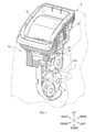
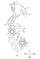
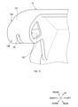
図1に示される乗物用シートロック装置10は、シートバック5を車両ボディ(図示せず。)に対して固定するためのロック装置である。当該シートバック5は、シートクッション(図示せず。)又は車両ボディに対して回転可能に連結されている。
(First Embodiment)
1. 1. Outline of the vehicle seat lock device The vehicle
シートバック5は着席者の背部を支持するための部位である。シートクッションは着席者の臀部を支持するための部位である。本実施形態に係る乗物用シートロック装置10は、シートバック5のシート幅方向一端側、つまりシートバック5のうち車両ボディに面した部位に装着される。
The seat back 5 is a portion for supporting the back of the seated person. The seat cushion is a part for supporting the buttocks of the seated person. The vehicle
乗物用シートを利用する者(以下、利用者という。)は、乗物用シートロック装置10を操作することにより、シートバック5を起立状態に固定する場合と当該シートバック5を回転可能状態とする場合とを切り換えることができる。
A person who uses a vehicle seat (hereinafter referred to as a user) operates the vehicle
2.乗物用シートロック装置の詳細
2.1 乗物用シートロック装置の構成
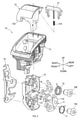
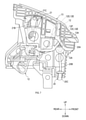
乗物用シートロック装置10は、図2に示されるように、フック11、操作レバー12、及びレバーケース13等を少なくとも備える。
2. 2. Details of the vehicle seat lock device 2.1 Configuration of the vehicle seat lock device As shown in FIG. 2, the vehicle
<フック等>
フック11は、図1に示されるように、ストライカー7に引っ掛かるように係合する係合部材である。ストライカー7は、車両ボディに対して固定された被係合部材の一例である。このため、フック11には、ストライカー7が嵌り込み可能な凹部11Aが設けられている。
<Hooks, etc.>
As shown in FIG. 1, the
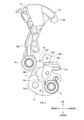
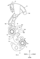
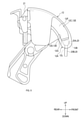
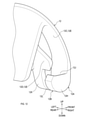
当該フック11は、ストライカー7と係合可能な係合位置(図3参照)と当該係合が解除可能な解除位置(図4及び図5参照)との間で変位可能である。本実施形態に係るフック11は、図2に示されるように、締結ブッシュ14Aを介してロックケース15に対して回転可能に装着されている。
The
ロックケース15は、ベースブラケット16を介してシートバック5、つまり乗物用シートに固定される。なお、ロックケース15は樹脂製である。ベースブラケット16は金属製である。つまり、ロックケース15は、ベースブラケット16により補強された状態でシートバック5に固定される。
The
フックスプリング17は、フック11を解除位置側に向けて変位させる弾性力Fs1(図3参照)を発揮可能な弾性体である。本実施形態に係るフックスプリング17は、締結ブッシュ14Aと同軸線状に配置された捻りコイルばねにより構成されている。
The
ポール18は、操作レバー12に入力された操作力をフック11に伝達する。当該ポール18は、締結ブッシュ14Bを介してロックケース15に対して回転可能に装着されている。
The
ポール18には、第1押圧部18A及び第2押圧部18B等が少なくともが設けられている。第1押圧部18A及び第2押圧部18Bは、フック11に設けられた被押圧部11Bに接触可能な部位である。
The
第1押圧部18Aは、図3に示されるように、フック11が係合位置にあるときに被押圧部11Bに接触する部位である。第2押圧部18Bは、図4に示されるように、フック11が解除位置にあるときに被押圧部11Bに接触する部位である。
As shown in FIG. 3, the first pressed
なお、第1押圧部18Aが被押圧部11Bに接触している状態では、第2押圧部18Bは被押圧部11Bと非接触状態となる。第2押圧部18Bが被押圧部11Bに接触している状態では、第1押圧部18Aは被押圧部11Bと非接触状態となる。
In the state where the first pressed
ポールスプリング19は、第1押圧部18A及び第2押圧部18Bを被押圧部11Bに押し付ける弾性力Fs2を発揮可能な弾性体である。つまり、ポールスプリング19は、図3の紙面において、ポール18を右向きに回転させる弾性力Fs2を発揮可能である。
The
ポール18の回転中心、フック11の回転中心、第1押圧部18A、第2押圧部18B及び被押圧部11Bは、少なくとも以下の要件を満たすように構成されている。
第1押圧部18A又は第2押圧部18Bが被押圧部11Bに接触している状態において、第1押圧部18Aが被押圧部11Bを押圧する力は、被押圧部11Bの曲率中心に向けて作用するように構成されている。このため、当該力は、フック11を回転させる回転力として寄与しない。
The rotation center of the
When the first pressed
<操作レバー等>
操作レバー12は、フック11を解除位置に変位させるための操作部材の一例である。当該操作レバー12は、利用者により直接的又は間接的に操作される。レバーケース13は、図6~図8に示されるように、操作レバー12を変位可能に支持するベース部の一例である。
<Operation lever, etc.>
The operating
操作レバー12は、待機位置(図6及び図9参照)、作用位置(図7及び図10参照)、及び作業位置(図8及び図11参照)を含む範囲内で変位可能である。待機位置は、操作レバー12に操作力が作用していないときの操作レバー12の位置である。操作レバー12が待機位置にある場合、通常、フック11は係合位置にある(図3参照)。
The operating
作用位置は、フック11が解除位置となるときの操作レバー12の位置である。換言すれば、作用位置は、利用者がフック11を解除位置とすることを目的として、当該利用者が待機位置にある操作レバー12に操作力を付与したときの操作レバー12の位置である。
The action position is the position of the operating
作業位置は、操作レバー12が使用範囲外に位置するときの当該操作レバー12の位置である。使用範囲は、待機位置から作用位置に至る範囲である。したがって、フック11を解除位置とすることを目的とした操作力が操作レバー12に付与された状態では、操作レバー12は、通常、使用範囲内に位置する。
The working position is the position of the operating
なお、本実施形態に係る操作レバー12は、レバーケース13に回転可能に支持されている。作用位置は、操作レバー12が待機位置よりシート前方側に回転変位した位置である。作業位置は、操作レバー12が作用位置よりシート前方側に回転変位した位置である。
The
<被係止部>
乗物用シートロック装置10は、図9に示されるように、被係止部12Aを備えている。被係止部12Aは、操作ケーブル20のケーブルエンド20Aが着脱自在に引っ掛かって係止される部位である。
<Locked part>
The vehicle
操作ケーブル20は、ケーブルエンド20A、インナーケーブル20B及びアウターチューブ20C(図6参照)等を有するコントロールケーブルである。インナーケーブル20Bは、可撓性を有するワイヤーである。
The
アウターチューブ20Cは、インナーケーブル20Bが変位可能に挿入された可撓性を有する管である。ケーブルエンド20Aは、インナーケーブル20Bの直径寸法より大きな外形寸法を有する部位であって、当該インナーケーブル20Bの端部に連結された部位である。
The
インナーケーブル20Bの端部のうちケーブルエンド20Aと反対側の端部は、遠隔操作部(図示せず。)に連結されている。利用者は、遠隔操作部を操作することにより、操作レバー12を間接的に操作できる。なお、本実施形態に係る遠隔操作部は、車両の荷室に設けられている。
Of the ends of the
被係止部12Aは、操作レバー12と一体的に変位する。本実施形態に係る被係止部12Aは、操作レバー12の一部として、当該操作レバー12と共に樹脂にて一体成形された一体成形部分である。
The locked
被係止部12Aは、図12及び図13に示されるように、係止壁12B及び案内部12E等を有して構成されている。係止壁12Bは、図9に示されるように、インナーケーブル20Bが貫通する貫通穴12Lを有し、かつ、ケーブルエンド20Aが離接変位可能な壁部である。
As shown in FIGS. 12 and 13, the locked
そして、当該係止壁12Bは、ケーブルエンド20Aが接触したときに当該ケーブルエンド20Aを係止する。なお、本実施形態に係るケーブルエンド20Aは円柱状である。このため、係止壁12Bは、ケーブルエンド20Aの外周面に沿うように円弧状の湾曲している。
Then, the locking
図9~図11に示されるように、ケーブルエンド20Aは、係止壁12Bに対して離接変位可能である。このため、係止壁12Bを挟んでアウターチューブ20Cと反対側には、ケーブルエンド20Aを変位可能とするための空間12Fが設けられている。
As shown in FIGS. 9 to 11, the
案内部12Eは、係止壁12Bから離間しているケーブルエンド20Aが当該係止壁12Bに接近変位する際に、当該ケーブルエンド20Aが予め決められた姿勢にて当該係止壁12Bに接触するように当該ケーブルエンド20Aの変位を案内することが可能な部位である。
The
具体的には、案内部12Eは、第1壁部12C及び第2壁部12Dを有して構成されている。第1壁部12Cは、空間12Fを挟んで第2壁部12Dから離間している。第1壁部12Cと第2壁部12Dとの離間距離は、概ねケーブルエンド20Aの直径寸法に等しい。
Specifically, the
このため、ケーブルエンド20Aの外周面が第1壁部12C及び第2壁部12Dに滑り接触するので、ケーブルエンド20Aの姿勢が拘束された状態で当該ケーブルエンド20Aが係止壁12Bに接近変位する。
Therefore, since the outer peripheral surface of the
第2壁部12Dと係止壁12Bとの間には、貫通穴12L及び空間12Fと連通する溝部12Gが設けられている。溝部12Gは、少なくともインナーケーブル20Bが貫通可能な幅寸法を有する。
A
係止壁12Bは、図12及び図13に示されるように、ケーブルエンド20Aが嵌り込み可能な箱状又は袋状に構成された部位に設けられている。すなわち、係止壁12Bの周囲のうち少なくとも1方向(本実施形態では、3方向)には、壁部12H、12J、12Kが設けられている。
As shown in FIGS. 12 and 13, the locking
壁部12H、12J、12Kは、係止壁12Bに係止されたケーブルエンド20Aを囲むように設けられている。なお、係止壁12B、壁部12H、12J、12K、第1壁部12C及び第2壁部12Dは樹脂にて一体成形された一体成形部である。
The
<カバー部>
図6に示されるように、レバーケース13にはカバー部13Aが設けられている。カバー部13Aは、被係止部12Aの少なくとも一部を覆うことにより、ケーブルエンド20Aが被係止部12Aから離脱することを規制可能な部位である。なお、本実施形態に係るカバー部13Aは、レバーケース13と共に樹脂にて一体成形された一体成形部分である。
<Cover part>
As shown in FIG. 6, the
そして、カバー部13A及び被係止部12Aは、少なくとも以下の(a)及び(b)の要件を満たすように構成されている。
(a)操作レバー12が使用範囲にある場合には、被係止部12Aからケーブルエンド20Aが離脱することを規制可能な状態となる。具体的には、使用範囲では、図6及び図7に示されるように、空間12F(図9参照)がカバー部13Aで覆われてケーブルエンド20Aが当該空間12Fから離脱不可な状態となる。
The
(A) When the operating
(b)操作レバー12が作業位置にある場合には、被係止部12Aからケーブルエンド20Aが離脱可能な状態になる。具体的には、作業位置では、図8に示されるように、空間12Fの一部が開放されてケーブルエンド20Aが当該空間12Fから離脱可能な状態となる。
(B) When the operating
<コーション部材>
乗物用シートロック装置10は、図3に示されるように、コーション部材21を備える。コーション部材21は、フック11の位置を示すインジケータ部である。当該コーション部材21は、フック11が係合位置にあることを示す第1位置(図3参照)と当該フック11が解除位置にあることを示す第2位置(図4及び図5参照)との間で変位可能である。
<Caution member>
The vehicle
すなわち、コーション部材21は、操作レバー12と一体的に回転変位しなら、当該操作レバー12に対して第1位置と第2位置との間で変位可能である。コーション部材21は、ばね21A(図2参照)から常に弾性力を受けている。
That is, if the
当該弾性力の向きは、コーション部材21を第1位置から第2位置に向けて変位させる向きである。さらに、コーション部材21には、図6に示されるように、レバーケース13に設けられたカム部21Bに滑り接触する摺接部21Cが設けられている。
The direction of the elastic force is the direction in which the
そして、操作レバー12が操作力を受けて回転変位すると、コーション部材21は、当該操作レバー12と一体的に回転変位する。このとき、摺接部21Cがカム部21Bに沿って変位するので、コーション部材21が第1位置と第2位置との間で変位する。
Then, when the operating
2.2 乗物用シートロック装置の作動
<ロック状態>
フック11が係合位置となると、当該フック11はストライカー7と係合してロック状態となる。ロック状態では、図3に示されるように、第1押圧部18Aが被押圧部11Bに接触する。
2.2 Operation of seat lock device for vehicles <Locked state>
When the
このとき、図示しないガタ抑えカムプレートは、フック11を係合位置側に向けて回転させる力を発生させる。なお、大荷重がフック11に入力された場合には、当接部11Cが第3押圧部18Cに係止されるため、ロック状態が保持される。
At this time, the backlash suppressing cam plate (not shown) generates a force for rotating the
<ロック状態→リリース状態>
ロック状態において、操作レバー12が操作されると、当該操作レバー12に入力された操作力が、図4に示されるように、ポールレバー18Cを介してポール18に伝達される。これにより、フック11は、第1押圧部18Aと被押圧部11Bとが非接触状態となり、かつ、第2押圧部18Bが被押圧部11Bに接触するように回転変位する。
<Locked state → Release state>
When the operating
つまり、フック11が係合位置から解除位置に回転変位してリリース状態となる。当該リリース状態では、第2押圧部18Bが被押圧部11Bを押圧する力は、被押圧部11Bの曲率中心に向けて作用する。このため、フックスプリング17が発揮する回転力により、フック11が解除位置に保持される。
That is, the
<リリース状態→ロック状態>
リリース状態において、シートバック5が利用者により起立状態まで起こされると、ストライカー7がフック11に接触し、フック11はストライカー7から押圧力を受ける。当該押圧力は、フック11を解除位置側から係合位置側に押圧する。このため、フック11とストライカー7とが係合してロック状態となる。
<Release state → Lock state>
In the released state, when the seat back 5 is raised to the upright state by the user, the
<作業位置>
利用者が使用範囲を超えて作業位置まで操作レバー12を変位させると、図5に示されるように、第1押圧部18A及び第2押圧部18Bが共に被押圧部11Bに対して非接触状態となる。このため、フック11は、フックスプリング17の弾性力に解除位置に保持される。
<Working position>
When the user displaces the
操作レバー12が作業位置まで到達すると、図8に示されるように、空間12Fの一部が開放されてケーブルエンド20Aが当該空間12Fから離脱可能な状態となる。つまり、被係止部12Aからケーブルエンド20Aが離脱可能な状態になる。
When the operating
3.本実施形態に係る乗物用シートロック装置の特徴
乗物用シートロック装置10では、操作レバー12が使用範囲にある場合には、被係止部12Aからケーブルエンド20Aが離脱することが抑制され得る。
3. 3. Features of the vehicle seat lock device according to the present embodiment In the vehicle
操作レバー12が作業位置になると、被係止部12Aからケーブルエンド20Aが離脱可能な状態になるので、作業者は、操作ケーブル20を乗物用シートロック装置10に組み付ける組付作業、及び操作ケーブル20を乗物用シートロック装置10から取り外す取外作業を容易に行うことができ得る。
When the
被係止部12Aは、係止壁12Bから離間しているケーブルエンド20Aが当該係止壁12Bに接近変位する際に、当該ケーブルエンド20Aが予め決められた姿勢にて当該係止壁12Bに接触するように当該ケーブルエンド20Aの変位を案内する案内部12Eを有している。
When the
これにより、インナーケーブル20Bが変位していない状態、つまり、インナーケーブル20Bに張力が作用していない状態において、操作レバー12が変位した場合、インナーケーブル20Bが撓むように曲がってしまうことが抑制される(図10参照)。したがって、被係止部12Aからケーブルエンド20Aが離脱することが抑制され得る。
As a result, when the
すなわち、通常、操作レバー12が待機位置にあるときには、係止壁12Bとケーブルエンド20Aとは接触した状態にある(図9参照)。当該状態において、遠隔操作部が操作されることなく、操作レバー12のみが操作されると、ケーブルエンド20Aは、係止壁12Bから離間するように当該係止壁12Bに対して相対変位する(図10参照)。
That is, normally, when the operating
したがって、遠隔操作部が操作されることなく、操作レバー12のみが操作された場合であっても、インナーケーブル20Bが撓むように曲がってしまうことが抑制される。なお、当該撓む箇所とは、インナーケーブル20Bのうち係止壁12Bとケーブルエンド20Aとの間に位置する箇所である。
Therefore, even if only the
因みに、ケーブルエンド20Aが係止壁12Bに対して固定された構成であると、ケーブルエンド20Aが被係止部12Aから離脱してしまう可能性がある。
すなわち、インナーケーブル20Bに張力が作用していない状態で操作レバー12が操作されると、ケーブルエンド20Aが操作レバー12と共に変位するため、インナーケーブル20Bが大きく撓んでしまうおそれがある。
Incidentally, if the
That is, if the
インナーケーブル20Bが大きく撓むと、ケーブルエンド20Aが被係止部12Aから離脱してしまう可能性がある。これに対して、本実施形態では、インナーケーブル20Bが大きく撓むことが抑制されるので、ケーブルエンド20Aが被係止部12Aから離脱してしまうことが抑制され得る。
If the
被係止部12Aには、案内部12Eが設けられているので、ケーブルエンド20Aが予め決められた姿勢にて当該係止壁12Bに接触するように当該ケーブルエンド20Aの変位を案内することができ得る。延いては、ケーブルエンド20Aが変位する際に、当該ケーブルエンド20Aがこじれてしまうことが抑制され得る。
Since the locked
係止壁12Bは、ケーブルエンド20Aが嵌り込み可能な箱状又は袋状に構成された部位に設けられている。これにより、係止壁12Bの機械的強度が向上し得る。
(その他の実施形態)
上述の実施形態では、ストライカー7が車両ボディに対して固定され、乗物用シートロック装置10がシートバック5に設けられていた。しかし、本明細書に開示された発明はこれに限定されるものではない。すなわち、当該発明は、例えば、ストライカー7がシートバック5に設けられ、乗物用シートロック装置10が車両ボディに対して固定されていてもよい。
The locking
(Other embodiments)
In the above-described embodiment, the
上述の実施形態に係る被係止部12Aは操作レバー12に一体成形された部位であった。しかし、本明細書に開示された発明はこれに限定されるものではない。すなわち、当該発明は、例えば、被係止部12Aが操作レバー12と別体として構成され、リンク機構等を介して操作レバー12と一体的に変位する構成であってもよい。
The locked
上述の実施形態に係る操作レバー12は、レバーケース13に回転可能に支持された構成であった。しかし、本明細書に開示された発明はこれに限定されるものではない。すなわち、当該発明は、例えば、操作レバー12がレバーケース13に対してスライド可能に支持された構成であってもよい。
The operating
上述の実施形態に係るカバー部13Aはレバーケース13に一体成形された部位であった。しかし、本明細書に開示された発明はこれに限定されるものではない。すなわち、当該発明は、例えば、カバー部13Aがレバーケース13と別体として構成され、当該カバー部13Aがレバーケース13に固定された構成であってもよい。
The
上述の実施形態では、ケーブルエンド20Aが係止壁12Bに対して離接変位可能であり、かつ、当該ケーブルエンド20Aの変位を案内する案内部12Eを有していた。しかし、本明細書に開示された発明はこれに限定されるものではない。すなわち、当該発明は、例えば、ケーブルエンド20Aが被係止部12Aに固定された構成であってもよい。
In the above-described embodiment, the
上述の実施形態に係る係止壁12Bは、ケーブルエンド20Aが嵌り込み可能な箱状又は袋状に構成された部位に設けられていた。しかし、本明細書に開示された発明はこれに限定されるものではない。すなわち、当該発明は、例えば、壁部12H等が廃止された構成、又は被係止部12Aがケーブルエンド20Aの全周囲を囲む箱状又は袋状の構成であってもよい。
The locking
上述の実施形態では、車両に本開示を適用した。しかし、本明細書に開示された発明の適用はこれに限定されるものではなく、鉄道車両、船舶及び航空機等の乗物に用いられるシート、並びに劇場や家庭用等に用いられる据え置き型シートにも適用できる。 In the embodiments described above, the present disclosure has been applied to the vehicle. However, the application of the invention disclosed in the present specification is not limited to this, and it is also applied to seats used for vehicles such as railroad vehicles, ships and aircraft, and stationary seats used for theaters and households. Applicable.
さらに、本開示は、上述の実施形態に記載された発明の趣旨に合致するものであればよく、上述の実施形態に限定されるものではない。したがって、上述した複数の実施形態のうち少なくとも2つの実施形態が組み合わせられた構成、又は上述の実施形態において、図示された構成要件もしくは符号を付して説明された構成要件のうちいずれかが廃止された構成でもよい。 Furthermore, the present disclosure is not limited to the above-described embodiment as long as it conforms to the gist of the invention described in the above-mentioned embodiment. Therefore, either the configuration in which at least two embodiments of the plurality of embodiments described above are combined, or the configuration requirements shown in the illustration or the configuration requirements described with reference numerals in the above-described embodiment are abolished. It may be a configured configuration.
5… シートバック 7… ストライカー 10… 乗物用シートロック装置
11… フック 11A… 凹部 11B… 被押圧部 11C… 当接部
12… 操作レバー 12A… 被係止部 12B… 係止壁
12L… 貫通穴 12F… 空間 12E… 案内部
12C… 第1壁部 12D… 第2壁部 12G… 溝部
12H… 壁部 13… レバーケース 13A… カバー部
14A… 締結ブッシュ 14B… 締結ブッシュ 15… ロックケース
16… ベースブラケット 17… フックスプリング
18… ポール 18A… 第1押圧部 18B… 第2押圧部 18C… 第3押圧部
19… ポールスプリング 20… 操作ケーブル
20A… ケーブルエンド 20B… インナーケーブル
5 ... Seat back 7 ...
Claims (3)
前記乗物又は前記シートに対して固定されたストライカーと係合可能な係合位置と当該係合が解除可能な解除位置との間で変位可能なフックと、
前記フックを前記解除位置に変位させるための操作部材と、
前記操作部材を変位可能に支持するベース部と、
前記操作部材と一体的に変位する被係止部であって、操作ケーブルのケーブルエンドが着脱自在に係止される被係止部と、
前記ベース部に設けられたカバー部であって、前記被係止部の少なくとも一部を覆うことにより、前記ケーブルエンドが前記被係止部から離脱することを規制可能なカバー部とを備え、
前記操作部材は、当該操作部材に操作力が作用していない位置である待機位置、前記フックを前記解除位置とする作用位置、及び前記待機位置から前記作用位置に至る使用範囲の外である作業位置を含む範囲内で変位可能であり、
さらに、前記カバー部及び前記被係止部は、
前記操作部材が前記使用範囲にある場合には、前記被係止部から前記ケーブルエンドが離脱することを規制可能な状態となり、かつ
前記操作部材が前記作業位置にある場合には、前記被係止部から前記ケーブルエンドが離脱可能な状態になるように構成されている
乗物用シートロック装置。 In the vehicle seat lock device applied to the vehicle seat,
A hook that can be displaced between an engagement position that can engage with the striker fixed to the vehicle or the seat and a disengagement position that can disengage the engagement.
An operating member for displacing the hook to the release position, and
A base portion that displaceably supports the operating member and
A locked portion that is integrally displaced with the operating member, and a locked portion in which the cable end of the operation cable is detachably locked.
A cover portion provided on the base portion, comprising a cover portion capable of restricting the cable end from being detached from the locked portion by covering at least a part of the locked portion.
The operating member is a work that is outside the standby position where the operating force is not acting on the operating member, the acting position where the hook is the release position, and the range of use from the standby position to the acting position. It can be displaced within the range including the position,
Further, the cover portion and the locked portion are
When the operating member is within the range of use, the cable end can be restricted from being disengaged from the locked portion, and when the operating member is in the working position, the engaged member is engaged. A vehicle seat lock device configured so that the cable end can be detached from the stop.
前記操作ケーブルのインナーケーブルが貫通する貫通穴を有し、かつ、前記ケーブルエンドが離接変位可能な係止壁であって、前記ケーブルエンドが接触したときに当該ケーブルエンドを係止する係止壁、並びに
前記係止壁から離間している前記ケーブルエンドが当該係止壁に接近変位する際に、当該ケーブルエンドが予め決められた姿勢にて当該係止壁に接触するように当該ケーブルエンドの変位を案内する案内部
を有している請求項1に記載の乗物用シートロック装置。 The locked portion is
A locking wall that has a through hole through which the inner cable of the operation cable penetrates, and the cable end is a locking wall that can be detached and displaced, and locks the cable end when the cable end comes into contact. When the wall and the cable end separated from the locking wall are displaced close to the locking wall, the cable end is brought into contact with the locking wall in a predetermined posture. The vehicle seat lock device according to claim 1, which has a guide unit for guiding the displacement of the electric wire.
Priority Applications (1)
| Application Number | Priority Date | Filing Date | Title |
|---|---|---|---|
| JP2018130627A JP6996437B2 (en) | 2018-07-10 | 2018-07-10 | Vehicle seat lock device |
Applications Claiming Priority (1)
| Application Number | Priority Date | Filing Date | Title |
|---|---|---|---|
| JP2018130627A JP6996437B2 (en) | 2018-07-10 | 2018-07-10 | Vehicle seat lock device |
Publications (2)
| Publication Number | Publication Date |
|---|---|
| JP2020006848A JP2020006848A (en) | 2020-01-16 |
| JP6996437B2 true JP6996437B2 (en) | 2022-02-04 |
Family
ID=69150325
Family Applications (1)
| Application Number | Title | Priority Date | Filing Date |
|---|---|---|---|
| JP2018130627A Active JP6996437B2 (en) | 2018-07-10 | 2018-07-10 | Vehicle seat lock device |
Country Status (1)
| Country | Link |
|---|---|
| JP (1) | JP6996437B2 (en) |
Citations (1)
| Publication number | Priority date | Publication date | Assignee | Title |
|---|---|---|---|---|
| JP2014073702A (en) | 2012-10-02 | 2014-04-24 | Toyota Motor Corp | Vehicular seat |
-
2018
- 2018-07-10 JP JP2018130627A patent/JP6996437B2/en active Active
Patent Citations (1)
| Publication number | Priority date | Publication date | Assignee | Title |
|---|---|---|---|---|
| JP2014073702A (en) | 2012-10-02 | 2014-04-24 | Toyota Motor Corp | Vehicular seat |
Also Published As
| Publication number | Publication date |
|---|---|
| JP2020006848A (en) | 2020-01-16 |
Similar Documents
| Publication | Publication Date | Title |
|---|---|---|
| EP2415629B1 (en) | Seat slide apparatus for vehicle | |
| JP5990538B2 (en) | Rocking tongue | |
| JP2006518430A (en) | Hood latch assembly | |
| JP2014019294A (en) | Tang and seat belt device using same | |
| CN107489321B (en) | Engine hood lock, engine hood locking structure and vehicle | |
| JP6996437B2 (en) | Vehicle seat lock device | |
| WO2014171195A1 (en) | Buckle for seatbelt device | |
| JP7067409B2 (en) | Vehicle seat lock device | |
| JP5792110B2 (en) | Webbing take-up device | |
| KR101144858B1 (en) | Height adjust apparatus of seat for vehicle | |
| JP6488155B2 (en) | Headrest | |
| KR102402994B1 (en) | Seat swivel for vehicle | |
| GB2246507A (en) | Reinforced guide member for guiding a seat belt extracting from a retractor in the region of a belt gripping mechanism | |
| JP5763006B2 (en) | Webbing take-up device | |
| KR101916916B1 (en) | The folding device of the headrest | |
| EP2060960B1 (en) | Operation device for vehicle seat and other equipment | |
| JP2014073702A (en) | Vehicular seat | |
| JP2011256654A (en) | Door handle device of vehicle | |
| JP2017087929A (en) | Seat lock device | |
| JP6700036B2 (en) | Cable operating structure | |
| KR101542692B1 (en) | Hood latch for automobile | |
| CN112443402B (en) | Throttle grip device for receiving throttle operation of driver | |
| JP4613363B2 (en) | Armrest for vehicle seat | |
| JP7035766B2 (en) | Vehicle seat lock device | |
| US11390192B2 (en) | Slide device for vehicle seat |
Legal Events
| Date | Code | Title | Description |
|---|---|---|---|
| A621 | Written request for application examination |
Free format text: JAPANESE INTERMEDIATE CODE: A621 Effective date: 20210121 |
|
| A977 | Report on retrieval |
Free format text: JAPANESE INTERMEDIATE CODE: A971007 Effective date: 20211022 |
|
| TRDD | Decision of grant or rejection written | ||
| A01 | Written decision to grant a patent or to grant a registration (utility model) |
Free format text: JAPANESE INTERMEDIATE CODE: A01 Effective date: 20211116 |
|
| A61 | First payment of annual fees (during grant procedure) |
Free format text: JAPANESE INTERMEDIATE CODE: A61 Effective date: 20211129 |
|
| R151 | Written notification of patent or utility model registration |
Ref document number: 6996437 Country of ref document: JP Free format text: JAPANESE INTERMEDIATE CODE: R151 |
|
| R250 | Receipt of annual fees |
Free format text: JAPANESE INTERMEDIATE CODE: R250 |
|
| R250 | Receipt of annual fees |
Free format text: JAPANESE INTERMEDIATE CODE: R250 |