JP6996401B2 - tire - Google Patents
tire Download PDFInfo
- Publication number
- JP6996401B2 JP6996401B2 JP2018074057A JP2018074057A JP6996401B2 JP 6996401 B2 JP6996401 B2 JP 6996401B2 JP 2018074057 A JP2018074057 A JP 2018074057A JP 2018074057 A JP2018074057 A JP 2018074057A JP 6996401 B2 JP6996401 B2 JP 6996401B2
- Authority
- JP
- Japan
- Prior art keywords
- crown
- groove
- main groove
- sipe
- tire
- Prior art date
- Legal status (The legal status is an assumption and is not a legal conclusion. Google has not performed a legal analysis and makes no representation as to the accuracy of the status listed.)
- Active
Links
Images
Classifications
-
- B—PERFORMING OPERATIONS; TRANSPORTING
- B60—VEHICLES IN GENERAL
- B60C—VEHICLE TYRES; TYRE INFLATION; TYRE CHANGING; CONNECTING VALVES TO INFLATABLE ELASTIC BODIES IN GENERAL; DEVICES OR ARRANGEMENTS RELATED TO TYRES
- B60C11/00—Tyre tread bands; Tread patterns; Anti-skid inserts
- B60C11/03—Tread patterns
- B60C11/12—Tread patterns characterised by the use of narrow slits or incisions, e.g. sipes
- B60C11/1236—Tread patterns characterised by the use of narrow slits or incisions, e.g. sipes with special arrangements in the tread pattern
-
- B—PERFORMING OPERATIONS; TRANSPORTING
- B60—VEHICLES IN GENERAL
- B60C—VEHICLE TYRES; TYRE INFLATION; TYRE CHANGING; CONNECTING VALVES TO INFLATABLE ELASTIC BODIES IN GENERAL; DEVICES OR ARRANGEMENTS RELATED TO TYRES
- B60C11/00—Tyre tread bands; Tread patterns; Anti-skid inserts
- B60C11/03—Tread patterns
- B60C11/12—Tread patterns characterised by the use of narrow slits or incisions, e.g. sipes
- B60C11/1272—Width of the sipe
- B60C2011/1286—Width of the sipe being different from sipe to sipe
-
- Y—GENERAL TAGGING OF NEW TECHNOLOGICAL DEVELOPMENTS; GENERAL TAGGING OF CROSS-SECTIONAL TECHNOLOGIES SPANNING OVER SEVERAL SECTIONS OF THE IPC; TECHNICAL SUBJECTS COVERED BY FORMER USPC CROSS-REFERENCE ART COLLECTIONS [XRACs] AND DIGESTS
- Y02—TECHNOLOGIES OR APPLICATIONS FOR MITIGATION OR ADAPTATION AGAINST CLIMATE CHANGE
- Y02T—CLIMATE CHANGE MITIGATION TECHNOLOGIES RELATED TO TRANSPORTATION
- Y02T10/00—Road transport of goods or passengers
- Y02T10/80—Technologies aiming to reduce greenhouse gasses emissions common to all road transportation technologies
- Y02T10/86—Optimisation of rolling resistance, e.g. weight reduction
Landscapes
- Engineering & Computer Science (AREA)
- Mechanical Engineering (AREA)
- Tires In General (AREA)
Description
本発明は、操縦安定性能とウェット性能とを両立し得るタイヤに関する。 The present invention relates to a tire capable of achieving both steering stability performance and wet performance.
従来、タイヤ周方向に延びる複数の主溝を有するタイヤが知られている。この種のタイヤでは、操縦安定性能とウェット性能とを両立することが求められている。例えば、下記特許文献1のタイヤは、車両への装着の向きが指定されたトレッド部を有し、車両外側の剛性を高めることで操縦安定性能とウェット性能との両立を図っている。
Conventionally, a tire having a plurality of main grooves extending in the tire circumferential direction is known. This type of tire is required to have both steering stability performance and wet performance. For example, the tire of
しかしながら、タイヤに対する要求は、年々高まってきており、特許文献1のタイヤについても、更なる改善が求められていた。
However, the demand for tires has been increasing year by year, and further improvement has been required for the tires of
本発明は、以上のような実状に鑑み案出されたもので、操縦安定性能とウェット性能とを高次元で両立し得るタイヤを提供することを主たる目的としている。 The present invention has been devised in view of the above circumstances, and a main object of the present invention is to provide a tire capable of achieving both steering stability performance and wet performance at a high level.
本発明は、車両への装着の向きが指定されたトレッド部を有するタイヤであって、
前記トレッド部は、タイヤ周方向に延びる複数の主溝と、前記複数の主溝により区分される複数の陸部とを有し、
前記複数の主溝は、外側クラウン主溝と、車両装着時において、前記外側クラウン主溝よりも車両外側に位置する外側ショルダ主溝とを含み、
前記複数の陸部は、前記外側クラウン主溝と前記外側ショルダ主溝との間に区分される外側ミドル陸部、及び前記外側ショルダ主溝と外側トレッド端との間に区分される外側ショルダ陸部を含み、
前記外側ショルダ陸部には、タイヤ周方向にのびる周方向細溝と、前記外側トレッド端からのびかつ前記周方向細溝に連通するとともに前記外側ショルダ陸部内で終端する外側ショルダ横溝と、前記外側トレッド端から前記外側ショルダ主溝までのびる外側ショルダサイプとが設けられ、
前記外側ミドル陸部には、一端が前記外側ショルダ主溝に連通しかつ他端が前記外側ミドル陸部内で終端する外側ミドル短溝と、一端が前記外側クラウン主溝に連通しかつ他端が前記外側ミドル陸部内で終端する外側ミドルサイプとを具える。
The present invention is a tire having a tread portion whose mounting direction on a vehicle is specified.
The tread portion has a plurality of main grooves extending in the tire circumferential direction and a plurality of land portions classified by the plurality of main grooves.
The plurality of main grooves include an outer crown main groove and an outer shoulder main groove located outside the vehicle with respect to the outer crown main groove when mounted on a vehicle.
The plurality of land portions are an outer middle land portion divided between the outer crown main groove and the outer shoulder main groove, and an outer shoulder land divided between the outer shoulder main groove and the outer tread end. Including the part
In the outer shoulder land portion, a circumferential narrow groove extending in the tire circumferential direction, an outer shoulder lateral groove extending from the outer tread end and communicating with the circumferential fine groove, and terminating in the outer shoulder land portion, and the outer side. An outer shoulder sipe extending from the tread end to the outer shoulder main groove is provided.
In the outer middle land portion, one end communicates with the outer shoulder main groove and the other end communicates with the outer middle land portion and the other end communicates with the outer middle land portion, and one end communicates with the outer crown main groove and the other end thereof. It includes an outer middle sipe that terminates within the outer middle land.
本発明に係るタイヤでは、前記外側ショルダ横溝と前記外側ショルダサイプとは、タイヤ周方向に交互に配されるのが好ましい。 In the tire according to the present invention, the outer shoulder lateral groove and the outer shoulder sipe are preferably arranged alternately in the tire circumferential direction.
本発明に係るタイヤでは、前記外側ミドル短溝と前記外側ミドルサイプとは、タイヤ周方向に交互に配されるのが好ましい。 In the tire according to the present invention, the outer middle short groove and the outer middle sipe are preferably arranged alternately in the tire circumferential direction.
本発明に係るタイヤでは、前記外側ミドル短溝と前記外側ミドルサイプとはタイヤ軸方向で重複し、このタイヤ軸方向の重複幅は、前記外側ミドル陸部のタイヤ軸方向の陸部幅の10~30%であるのが好ましい。 In the tire according to the present invention, the outer middle short groove and the outer middle sipe overlap in the tire axial direction, and the overlapping width in the tire axial direction is 10 to 10 to the land width in the tire axial direction of the outer middle land portion. It is preferably 30%.
本発明に係るタイヤでは、前記複数の主溝は、車両装着時において、前記外側クラウン主溝よりも車両内側に位置する内側クラウン主溝と、前記内側クラウン主溝よりも車両内側に位置する内側ショルダ主溝とを含み、
前記複数の陸部は、前記外側クラウン主溝と前記内側クラウン主溝との間に区分されるクラウン陸部、前記内側クラウン主溝と前記内側ショルダ主溝との間に区分される内側ミドル陸部、及び前記内側ショルダ主溝と内側トレッド端との間に区分される内側ショルダ陸部を含み、
前記クラウン陸部には、一端が前記外側クラウン主溝に連通しかつ他端が前記クラウン陸部内で終端する第1クラウンサイプと、一端が前記内側クラウン主溝に連通しかつ他端が前記クラウン陸部内で終端する第2クラウンサイプとが設けられ、
前記第1クラウンサイプと前記第2クラウンサイプとは、タイヤ軸方向に対して同方向に傾斜するのが好ましい。
In the tire according to the present invention, the plurality of main grooves are the inner crown main groove located inside the vehicle from the outer crown main groove and the inner side located inside the vehicle than the inner crown main groove when mounted on the vehicle. Including the shoulder main groove
The plurality of land portions are a crown land portion divided between the outer crown main groove and the inner crown main groove, and an inner middle land divided between the inner crown main groove and the inner shoulder main groove. Including the portion and the inner shoulder land portion partitioned between the inner shoulder main groove and the inner tread end.
The crown land portion has a first crown sipe having one end communicating with the outer crown main groove and the other end communicating within the crown land portion, and one end communicating with the inner crown main groove and the other end having the crown. A second crown sipe that terminates in the land is provided,
It is preferable that the first crown sipe and the second crown sipe are inclined in the same direction with respect to the tire axial direction.
本発明に係るタイヤでは、前記第1クラウンサイプのタイヤ軸方向に対する角度θ1は、前記第2クラウンサイプのタイヤ軸方向に対する角度θ2より小であるのが好ましい。 In the tire according to the present invention, the angle θ1 of the first crown sipe with respect to the tire axial direction is preferably smaller than the angle θ2 of the second crown sipe with respect to the tire axial direction.
本発明に係るタイヤでは、前記第1クラウンサイプのタイヤ軸方向の長さL1は、前記第2クラウンサイプのタイヤ軸方向の長さL2より大であるのが好ましい。 In the tire according to the present invention, the length L1 of the first crown sipe in the tire axial direction is preferably larger than the length L2 of the second crown sipe in the tire axial direction.
本発明に係るタイヤでは、前記クラウン陸部には、前記外側クラウン主溝から前記内側クラウン主溝までのび、かつ深さが2mm未満のクラウン浅溝が設けられるとともに、前記クラウン浅溝の底部に、前記第1クラウンサイプと前記第2クラウンサイプとが設けられるのが好ましい。 In the tire according to the present invention, the land portion of the crown is provided with a shallow crown groove extending from the outer crown main groove to the inner crown main groove and having a depth of less than 2 mm, and the bottom of the shallow crown groove. , The first crown sipe and the second crown sipe are preferably provided.
本明細書において、サイプとは、接地時にサイプ壁面の少なくとも一部同士が互いに接触しうる切れ込みであり、好ましくは幅1.5mm未満のである。 In the present specification, the sipe is a notch in which at least a part of the wall surface of the sipe can come into contact with each other at the time of touchdown, and the width is preferably less than 1.5 mm.
本発明は、操縦安定性能への影響力が大きい外側ショルダ陸部及び外側ミドル陸部に着目してなされている。 The present invention has focused on the outer shoulder land portion and the outer middle land portion, which have a large influence on the steering stability performance.
外側ショルダ陸部においては、外側トレッド端からのびる外側ショルダ横溝が、外側ショルダ陸部内で終端している。そのため、外側ショルダ陸部の剛性が高まり、操縦安定性能の向上を図ることができる。又各外側ショルダ横溝が、周方向細溝に連通するとともに、外側トレッド端からのびる外側ショルダサイプが、外側ショルダ主溝に連通している。これにより、外側ショルダ横溝が外側ショルダ陸部内で終端することに起因する排水性の低下を補い、優れたウエット性能を発揮することが可能になる。 In the outer shoulder land, the outer shoulder lateral groove extending from the outer tread end terminates within the outer shoulder land. Therefore, the rigidity of the outer shoulder land portion is increased, and the steering stability performance can be improved. Further, each outer shoulder lateral groove communicates with the circumferential narrow groove, and the outer shoulder sipe extending from the outer tread end communicates with the outer shoulder main groove. This makes it possible to compensate for the decrease in drainage property caused by the termination of the outer shoulder lateral groove in the land portion of the outer shoulder, and to exhibit excellent wet performance.
しかも、外側ショルダサイプが、外側ショルダ陸部を横断することにより、外側ショルダ陸部に、入力が加えられた際に捻り剛性が適切に発生する。これにより、特に、初期応答性の向上に貢献しうる。 Moreover, since the outer shoulder sipe crosses the outer shoulder land, torsional rigidity is appropriately generated when an input is applied to the outer shoulder land. This can contribute to the improvement of the initial responsiveness in particular.
又外側ミドル陸部においても、外側ショルダ主溝からのびる外側ミドル短溝、及び外側クラウン主溝からのびる外側ミドルサイプが、それぞれ外側ミドル陸部内で終端している。そのため、ウエット性能を確保しながら、外側ミドル陸部の剛性を高めうる。その結果、前述の外側ショルダ陸部と協働して、操縦安定性能とウェット性能とを高次元で両立させることが可能となる。 Also in the outer middle land area, the outer middle short groove extending from the outer shoulder main groove and the outer middle sipe extending from the outer crown main groove are terminated in the outer middle land area, respectively. Therefore, the rigidity of the outer middle land portion can be increased while ensuring the wet performance. As a result, in cooperation with the above-mentioned outer shoulder land area, it becomes possible to achieve both steering stability performance and wet performance at a high level.
以下、本発明の実施の一形態が図面に基づき説明される。
図1は、本発明の一実施形態を示すタイヤ1のトレッド部2の展開図である。本実施形態のタイヤ1は、例えば、乗用車用や重荷重用の空気入りタイヤ、及び、タイヤの内部に加圧された空気が充填されない非空気式タイヤ等の様々なタイヤに用いることができる。本実施形態のタイヤ1は、特に乗用車用の空気入りタイヤとして好適に用いられる。
Hereinafter, embodiments of the present invention will be described with reference to the drawings.
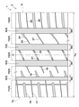
FIG. 1 is a developed view of a
図1に示されるように、本実施形態のタイヤ1は、車両への装着の向きが指定されたトレッド部2を有している。トレッド部2は、車両装着時において、タイヤ1の車両外側に位置する外側トレッド端Toと、車両内側に位置する内側トレッド端Tiとを有している。車両への装着の向きは、例えば、サイドウォール部(図示省略)に、文字又は記号で表示される。
As shown in FIG. 1, the
各トレッド端To、Tiは、空気入りタイヤの場合、正規状態のタイヤ1に正規荷重が負荷されキャンバー角0°で平面に接地したときの最もタイヤ軸方向外側の接地位置である。ここで、「正規状態」とは、タイヤ1が正規リムにリム組みされかつ正規内圧に調整された無負荷の状態である。以下、特に言及されない場合、タイヤ1の各部の寸法等は、この正規状態で測定された値である。
In the case of a pneumatic tire, each tread end To and Ti are the most outer contact positions in the tire axial direction when a normal load is applied to the
「正規リム」は、タイヤが基づいている規格を含む規格体系において、当該規格がタイヤ毎に定めるリムであり、例えばJATMAであれば "標準リム" 、TRAであれば "Design Rim" 、ETRTOであれば "Measuring Rim" である。 A "regular rim" is a rim defined for each tire in the standard system including the standard on which the tire is based. For example, "standard rim" for JATMA, "Design Rim" for TRA, and ETRTO. If there is, it is "Measuring Rim".
「正規内圧」は、タイヤが基づいている規格を含む規格体系において、各規格がタイヤ毎に定めている空気圧であり、JATMAであれば "最高空気圧" 、TRAであれば表 "TIRE LOAD LIMITS AT VARIOUS COLD INFLATION PRESSURES" に記載の最大値、ETRTOであれば "INFLATION PRESSURE" である。 "Regular internal pressure" is the air pressure defined for each tire in the standard system including the standard on which the tire is based. For JATTA, "maximum air pressure", for TRA, the table "TIRE LOAD LIMITS AT" The maximum value described in "VARIOUS COLD INFLATION PRESSURES", or "INFLATION PRESSURE" for ETRTO.
「正規荷重」は、タイヤが基づいている規格を含む規格体系において、各規格がタイヤ毎に定めている荷重であり、JATMAであれば "最大負荷能力" 、TRAであれば表 "TIRE LOAD LIMITS AT VARIOUS COLD INFLATION PRESSURES" に記載の最大値、ETRTOであれば "LOAD CAPACITY" である。 "Regular load" is the load defined for each tire in the standard system including the standard on which the tire is based. "Maximum load capacity" for JATTA and "TIRE LOAD LIMITS" for TRA. The maximum value described in "AT VARIOUS COLD INFLATION PRESSURES", or "LOAD CAPACITY" for ETRTO.
本実施形態のトレッド部2は、タイヤ周方向に延びる複数の主溝3と、複数の主溝3により区分される複数の陸部4とを有する。複数の主溝3は、それぞれ、トレッド幅Twの2%以上の溝幅W1~W4を有する。ここで、トレッド幅Twは、正規状態での外側トレッド端Toから内側トレッド端Tiまでのタイヤ軸方向の距離である。
The
本実施形態の複数の主溝3は、外側クラウン主溝5と、車両装着時において、外側クラウン主溝5よりも車両外側に位置する外側ショルダ主溝6とを含む。外側クラウン主溝5は、例えば、タイヤ赤道Cと外側トレッド端Toとの間を、タイヤ周方向に連続して直線状に延びる。外側ショルダ主溝6は、外側クラウン主溝5と外側トレッド端Toとの間を、タイヤ周方向に連続して直線状に延びる。
The plurality of
本実施形態の複数の主溝3は、車両装着時において、外側クラウン主溝5よりも車両内側に位置する内側クラウン主溝7と、この内側クラウン主溝7よりも車両内側に位置する内側ショルダ主溝8とをさらに含む。内側クラウン主溝7は、例えば、タイヤ赤道Cと内側トレッド端Tiとの間を、タイヤ周方向に連続して直線状に延びる。内側ショルダ主溝8は、内側クラウン主溝7と内側トレッド端Tiとの間を、タイヤ周方向に連続して直線状に延びる。
The plurality of
車両装着時にタイヤ赤道Cよりも外側となる外トレッド領域は、旋回時や車線変更時に大きな荷重が負荷される領域であり、操縦安定性能への影響が大きい。そのため、操縦安定性能の向上の観点から、外トレッド領域においてはランド比を増やして剛性を高めることが有効である。又タイヤ全体としてのウエット性能を確保するためには、タイヤ赤道Cよりも内側となる内トレッド領域において、ランド比を減らして排水性を高めることが有効である。 The outer tread region, which is outside the tire equator C when mounted on a vehicle, is a region in which a large load is applied when turning or changing lanes, and has a large effect on steering stability performance. Therefore, from the viewpoint of improving steering stability performance, it is effective to increase the land ratio to increase the rigidity in the outer tread region. Further, in order to secure the wet performance of the tire as a whole, it is effective to reduce the land ratio and improve the drainage property in the inner tread region inside the tire equator C.
このような見地から、外側ショルダ主溝6の溝幅W2は、外側クラウン主溝5の溝幅W1、内側クラウン主溝7の溝幅W3、及び内側ショルダ主溝8の溝幅W4よりも小であるのが望ましい。又タイヤ赤道C側は、トレッド端To、Ti側に比して排水し難いため、外側クラウン主溝5の溝幅W1及び内側クラウン主溝7の溝幅W3は、内側ショルダ主溝8の溝幅W4よりも大であるのが望ましい。又溝幅W1~W4の合計(W1+W2+W3+W4)は、トレッド幅Twの22%~28%の範囲であるのが、操縦安定性とウェット性能とのバランスの観点から好ましい。
From this point of view, the groove width W2 of the outer shoulder
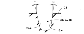
図6は主溝3の溝長さ方向と直交する溝断面が示される。図6に示されるように、各主溝3は、それぞれ、外側の溝壁面3woと、内側の溝壁面3wiとを具える。各主溝3において、トレッド踏面2Sの法線に対する外側の溝壁面3woの角度αoは、トレッド踏面2Sの法線に対する内側の溝壁面3wiの角度αiよりも大に設定されている。これにより、溝壁面3wi、3woの各角度が(αo+αi)/2で互い等しい場合に比して、旋回時や車線変更時に作用する車両外向きの横力に対しての横剛性を高めることができる。即ち、溝容積を同じとしながら、操縦安定性を高めることが可能になる。角度αoは10~12°の範囲が好ましく、角度αiは8~10°の範囲が好ましい。角度差(αo-αi)は、2°以上が好ましい。なお各主溝3の溝深さは、慣例に従って適宜採用しうる。
FIG. 6 shows a groove cross section orthogonal to the groove length direction of the
図1に示されるように、複数の陸部4は、外側クラウン主溝5と外側ショルダ主溝6との間に区分される外側ミドル陸部10、及び外側ショルダ主溝6と外側トレッド端Toとの間に区分される外側ショルダ陸部11を含む。複数の陸部4は、さらに、外側クラウン主溝5と内側クラウン主溝7との間に区分されるクラウン陸部12、内側クラウン主溝7と内側ショルダ主溝8との間に区分される内側ミドル陸部13、及び内側ショルダ主溝8と内側トレッド端Tiとの間に区分される内側ショルダ陸部14を含む。
As shown in FIG. 1, the plurality of
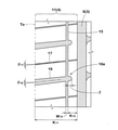
図2は、外側ショルダ陸部11の拡大図である。図2に示されるように、本実施形態の外側ショルダ陸部11には、1本の周方向細溝15と、複数本の外側ショルダ横溝16と、複数本の外側ショルダサイプ17とが設けられる。
FIG. 2 is an enlarged view of the outer
周方向細溝15は、外側ショルダ主溝6と外側トレッド端Toとの間でタイヤ周方向にのびる。周方向細溝15は、外側ショルダサイプ17よりも幅広、かつ主溝3及び外側ショルダ横溝16よりも幅狭の溝である。周方向細溝15の溝幅W15の下限は、好ましくは1.5mm以上であり、上限は好ましくは3mm以下である。
The circumferential
周方向細溝15は、外側ショルダ主溝6から離れすぎると、外側ショルダ陸部11の排水性に悪影響を及ぼし、近すぎると外側ショルダ陸部11の剛性に悪影響を及ぼす。そのため、周方向細溝15と外側ショルダ主溝6との間のタイヤ軸方向の距離K15は、外側ショルダ陸部11の陸部幅K11の15~30%であるのが好ましい。
If the circumferential
外側ショルダ横溝16は、外側トレッド端Toから車両内側に向かってのびかつ周方向細溝15に連通するとともに外側ショルダ陸部11内で終端する。又外側ショルダサイプ17は、外側トレッド端Toから周方向細溝15を越えて外側ショルダ主溝6までのびる。
The outer shoulder
このように、外側ショルダ横溝16では、その先端部16eが外側ショルダ陸部11内で終端しているため、外側ショルダ陸部11の剛性を高く維持することができる。
As described above, in the outer shoulder
又外側ショルダ横溝16が周方向細溝15に連通することにより、優れた排水効果が発揮される。又外側ショルダサイプ17が、外側ショルダ陸部11を横断することにより、路面上の水膜への高いワイピング効果及びエッジ効果が発揮さる。そしてこれら排水効果とワイピング効果及びエッジ効果との相互作用により、外側ショルダ横溝16の先端部16eが外側ショルダ陸部11内で終端することに起因する排水性の低下を補い、優れたウエット性能を発揮することが可能になる。又外側ショルダ陸部11に路面から力が作用した際、外側ショルダサイプ17によって捻り剛性が適切に発生し、特に、初期応答性の向上に貢献しうる。
Further, when the outer shoulder
本実施形態では、外側ショルダ横溝16の先端部16eが、周方向細溝15からはみ出した場合が示される。この場合、はみ出し量δは、前記距離K15の50%以下、さらには30%以下が好ましい。なお先端部16eは、周方向細溝15からはみ出すことなく終端してもよい。
In the present embodiment, the case where the
外側ショルダ横溝16と外側ショルダサイプ17とは、タイヤ周方向に交互に配されるのが好ましい。又外側ショルダ横溝16と外側ショルダサイプ17とは、タイヤ軸方向に対して同方向に傾斜するのが好ましく、特には、互いに略平行に配されるのがより好ましい。外側ショルダ横溝16のタイヤ軸方向に対する角度θ16、及び外側ショルダサイプ17のタイヤ軸方向に対する角度θ17は、それぞれ3~20°の範囲が好ましい。「略平行」とは、平行であるものと、平行に対し±5°以内の角度で傾斜するものとを含む。
The outer shoulder
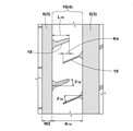
図3は、外側ミドル陸部10の拡大図である。図3に示されるように、本実施形態の外側ミドル陸部10には、複数の外側ミドル短溝18と、複数の外側ミドルサイプ19とが設けられる。
FIG. 3 is an enlarged view of the outer
外側ミドル短溝18は、一端が外側ショルダ主溝6に連通し、かつ他端が外側ミドル陸部10内で終端する。外側ミドルサイプ19は、一端が外側クラウン主溝5に連通し、かつ他端が外側ミドル陸部10内で終端する。
The outer middle
このような外側ミドル短溝18及び外側ミドルサイプ19は、外側ミドル陸部10の剛性を高く維持し、操縦安定性の向上に貢献しうる。又外側ミドル短溝18による排水効果と、外側ミドルサイプ19によるワイピング効果及びエッジ効果とにより、ウエット性能を発揮することができる。なお溝幅W2が小である外側ショルダ主溝6に、外側ミドル短溝18を連通させているため、ウエット性能を、外トレッド領域全体に亘ってバランス良く発揮させることができる。
Such an outer middle
外側ミドル短溝18と外側ミドルサイプ19とは、タイヤ周方向に交互に配されるのが好ましい。又外側ミドル短溝18と外側ミドルサイプ19とは、タイヤ軸方向に対して同方向に傾斜するのが好ましく、特には、互いに略平行に配されるのがより好ましい。なお外側ミドル短溝18のタイヤ軸方向に対する角度θ18、及び外側ミドルサイプ19のタイヤ軸方向に対する角度θ19は、それぞれ前記角度θ16、θ17よりも大であるのが好ましく、特には15~30°の範囲がより好ましい。「略平行」とは、平行であるものと、平行に対し±5°以内の角度で傾斜するものとを含む。
The outer middle
外側ミドル短溝18のタイヤ軸方向長さL18は、外側ミドル陸部10の陸部幅K10の40~70%が好ましい。長さL18が陸部幅K10の40%を下回ると、ウエット性能が不足傾向となり、逆に70%を越えると外側ミドル陸部10の剛性が不足傾向となる。又ウエット性能の観点から、外側ミドル短溝18と外側ミドルサイプ19とは、タイヤ軸方向で重複するのが好ましく、この重複幅Kaは、前記陸部幅K10の10~30%がより好ましい。
The tire axial length L 18 of the outer middle
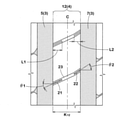
図4は、クラウン陸部12の拡大図である。図4に示されるように、本実施形態のクラウン陸部12には、複数の第1クラウンサイプ21と、複数の第2クラウンサイプ22とが設けられる。第1クラウンサイプ21は、一端が外側クラウン主溝5に連通し、かつ他端がクラウン陸部12内で終端する。第2クラウンサイプ22は、一端が内側クラウン主溝7に連通し、かつ他端がクラウン陸部12内で終端する。第1クラウンサイプ21と第2クラウンサイプ22とは、タイヤ周方向に交互に配される。
FIG. 4 is an enlarged view of the
このような第1クラウンサイプ21及び第2クラウンサイプ22は、クラウン陸部12の剛性を高く維持し、操縦安定性の向上に貢献しうる。又ワイピング効果及びエッジ効果により、ウエット性能を発揮しうる。
Such a
第1クラウンサイプ21と第2クラウンサイプ22とは、タイヤ軸方向に対して同方向に傾斜している。特には、第1クラウンサイプ21のタイヤ軸方向に対する角度θ1は、前記第2クラウンサイプのタイヤ軸方向に対する角度θ2よりも小であるのが好ましい。これにより、第1クラウンサイプ21によるワイピング効果及びエッジ効果を、第2クラウンサイプ22によるワイピング効果及びエッジ効果よりも相対的に高め、ランド比が高い外トレッド領域と、ランド比が低い内トレッド領域とにおけるウエット性能のバランス化を図っている。角度θ1は10~40°の範囲が好適であり、角度θ2は30~45°の範囲が好適である。その差(θ2-θ1)は、5°以上が好ましい。
The
同目的で、第1クラウンサイプ21のタイヤ軸方向の長さL1は、第2クラウンサイプ22のタイヤ軸方向の長さL2よりも大であるのが好ましい。長さL1はクラウン陸部12の陸部幅K12の25%~45%の範囲が好ましく、又長さL2はクラウン陸部12の陸部幅K12の20%~40%の範囲が好ましい。
For the same purpose, it is preferable that the length L1 of the
本実施形態では、第1クラウンサイプ21及び第2クラウンサイプ22は、深さが2mm未満のクラウン浅溝23の底部に設けられている。クラウン浅溝23は、外側クラウン主溝5から内側クラウン主溝7まで、第1クラウンサイプ21及び第2クラウンサイプ22に沿ってのびる。このようなクラウン浅溝23は、クラウン陸部12の剛性を高く維持しながら、排水性を高めるために役立つ。なおクラウン浅溝23の溝幅は2~5mmが好適である。
In the present embodiment, the
なおクラウン浅溝23を除去することができる。又第1クラウンサイプ21及び第2クラウンサイプ22が配される部分のみにクラウン浅溝23を形成し、第1クラウンサイプ21と第2クラウンサイプ22との間にて、クラウン浅溝23を除去することもできる。逆に、第1クラウンサイプ21と第2クラウンサイプ22との間のみにクラウン浅溝23を形成することもできる。
The crown
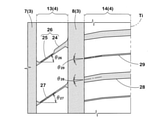
図5は、内側ミドル陸部13及び内側ショルダ陸部14の拡大図である。図5に示されるように、内側ミドル陸部13には、内側ミドル短溝24と内側ミドルサイプ25とからなる複合溝26が配される。内側ミドル短溝24は、一端が内側ショルダ主溝8に連通し、かつ他端が内側ミドル陸部13内で終端する。又内側ミドルサイプ25は、内側ミドル短溝24の前記他端から内側クラウン主溝7までのびる。この複合溝26は、内側ミドル短溝24と内側ミドルサイプ25とを別々に形成した場合に比して、排水効果と、ワイピング効果及びエッジ効果をより発揮させることができる。
FIG. 5 is an enlarged view of the inner
内側ミドル陸部13には、内側ショルダ主溝8から内側クラウン主溝7までのびる第2の内側ミドルサイプ27がさらに配される。この第2の内側ミドルサイプ27と複合溝26とはタイヤ周方向に交互に配される。前記複合溝26と第2の内側ミドルサイプ27とは、タイヤ軸方向に対して同方向に傾斜するのが好ましく、特には、互いに略平行に配されるのがより好ましい。「略平行」とは、平行であるものと、平行に対し±5°以内の角度で傾斜するものとを含む。
A second
複合溝26のタイヤ軸方向に対する角度θ26、及び第2の内側ミドルサイプ27のタイヤ軸方向に対する角度θ27は、それぞれ30~45°の範囲が好ましい。特には、前記角度θ2との差が5°以下であるのがより好ましい。
The angle θ 26 of the
外側ミドルサイプ19と、第1クラウンサイプ21と、第2クラウンサイプ22と複合溝26と、第2の内側ミドルサイプ27とは、タイヤ軸方向に対して同方向に傾斜するのが好ましい。特に本実施形態では、外側ミドルサイプ19と、第1クラウンサイプ21と、第2クラウンサイプ22と、複合溝26とが、主溝3を介して、滑らかに連続している。同様に、外側ミドルサイプ19と、第1クラウンサイプ21と、第2クラウンサイプ22と、第2の内側ミドルサイプ27とが、主溝3を介して、滑らかに連続している。これにより、トレッド部2に路面から力が作用した際、トレッド部2に捻り剛性が適切に発生し、初期応答性の向上を図ることができる。
The outer
内側ショルダ陸部14には、内側トレッド端Tiから内側ショルダ主溝8までのびる複数の内側ショルダ横溝28が設けられる。この内側ショルダ横溝28は、内側ショルダ陸部14を横断することで優れた排水効果を発揮する。これにより、内トレッド領域におけるウエット性能を外トレッド領域に比して相対的に高め、優れた操縦安定性を発揮しながら、タイヤ全体としてのウエット性能の向上が図られる。
The inner
特に本実施形態では、内側ショルダ陸部14には、内側トレッド端Tiから内側ショルダ主溝8までのびる複数の内側ショルダサイプ29が設けられる。この内側ショルダサイプ29は、内側ショルダ陸部14を横断することで優れたワイピング効果及びエッジ効果を発揮し、タイヤ全体としてのウエット性能のさらなる向上が図られる。
In particular, in the present embodiment, the inner
内側ショルダ横溝28と内側ショルダサイプ29とは、タイヤ周方向に交互に配されるのが好ましい。又内側ショルダ横溝28と内側ショルダサイプ29とは、タイヤ軸方向に対して同方向に傾斜するのが好ましく、特には、互いに略平行に配されるのがより好ましい。内側ショルダ横溝28のタイヤ軸方向に対する角度θ28、及び内側ショルダサイプ29のタイヤ軸方向に対する角度θ29は、それぞれ3~20°の範囲が好ましい。「略平行」とは、平行であるものと、平行に対し±5°以内の角度で傾斜するものとを含む。
The inner shoulder
以上、本発明の特に好ましい実施形態について詳述したが、本発明は、上述の実施形態に限定されることなく、種々の態様に変形して実施し得る。 Although the particularly preferred embodiment of the present invention has been described in detail above, the present invention is not limited to the above-described embodiment and can be modified into various embodiments.
図1の基本パターンを有するタイヤが、表1の仕様に基づき試作された。各テストタイヤの操縦安定性能及びウェット性能がテストされた。各テストタイヤの共通仕様やテスト方法は、以下のとおりである。 A tire having the basic pattern shown in FIG. 1 was prototyped based on the specifications shown in Table 1. The steering stability and wet performance of each test tire were tested. The common specifications and test methods for each test tire are as follows.
タイヤサイズ:205/55R16
リムサイズ:16×6.5JJ
空気圧:230kPa
テスト車両:前輪駆動車、排気量2000cc
タイヤ装着位置:全輪
Tire size: 205 / 55R16
Rim size: 16 x 6.5JJ
Air pressure: 230 kPa
Test vehicle: Front-wheel drive vehicle, displacement 2000cc
Tire mounting position: All wheels
<操縦安定性能>
上記テスト車両でドライ路面を走行したときの操縦安定性が、運転者の官能により評価された。結果は、比較例1を100とする指数で表され、数値が大きいほど操縦安定性能が優れていることを示す。
<Maneuvering stability performance>
The steering stability of the test vehicle when traveling on a dry road surface was evaluated by the driver's sensuality. The result is represented by an index with Comparative Example 1 as 100, and the larger the value, the better the steering stability performance.
<ウェット性能>
(1)ハイドロ性能:
上記テスト車両で、水深5mmかつ長さ20mの水たまりが設けられた半径100mのアスファルト路面を走行し、前輪の横加速度(横G)が計測され、速度50~80km/hの平均横Gが求められた。結果は、比較例1の値を100とする指数で表され、数値が大きいほどウェット性能が優れていることを示す。
(2)ウエットグリップ性能:
上記テスト車両で、ウェット路面(撒水したアスファルト路面)を走行し、初速度40km/hからの制動距離が測定された。結果は、比較例1を100とする指数で表され、数値が大きいほど制動距離が短くウエット性能が優れていることを示す。
<Wet performance>
(1) Hydro performance:
The above test vehicle travels on an asphalt road surface with a depth of 5 mm and a length of 20 m and a radius of 100 m, the lateral acceleration (lateral G) of the front wheels is measured, and the average lateral G at a speed of 50 to 80 km / h is obtained. Was done. The result is represented by an index with the value of Comparative Example 1 as 100, and the larger the value, the better the wet performance.
(2) Wet grip performance:
The test vehicle traveled on a wet road surface (sprinkled asphalt road surface), and the braking distance from an initial speed of 40 km / h was measured. The result is represented by an index with Comparative Example 1 as 100, and the larger the value, the shorter the braking distance and the better the wet performance.
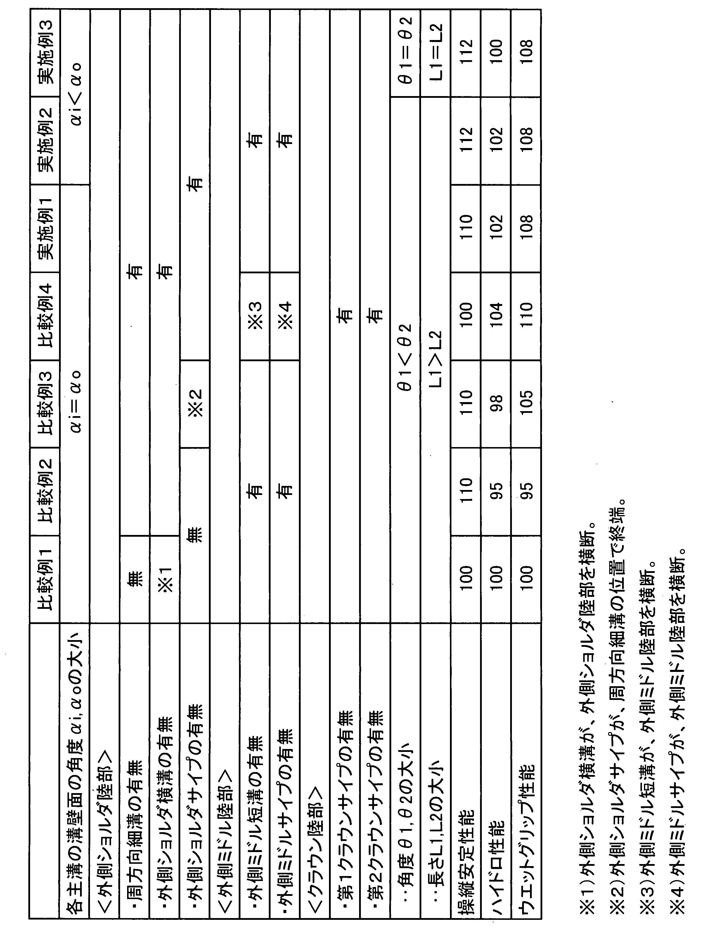
テストの結果、実施例のタイヤは、比較例に対して、操縦安定性能とウェット性能(ハイドロ性能及びウエットグリップ性能)とを高次元でバランスよく両立していることが確認できた。 As a result of the test, it was confirmed that the tires of the examples had both steering stability performance and wet performance (hydro performance and wet grip performance) in a high-dimensional and well-balanced manner as compared with the comparative example.
1 タイヤ
2S トレッド踏面
2 トレッド部
3wi 溝壁面
3wo 溝壁面
3 主溝
4 陸部
5 外側クラウン主溝
6 外側ショルダ主溝
7 内側クラウン主溝
8 内側ショルダ主溝
10 外側ミドル陸部
11 外側ショルダ陸部
12 クラウン陸部
13 内側ミドル陸部
14 内側ショルダ陸部
15 周方向細溝
16 外側ショルダ横溝
17 外側ショルダサイプ
18 外側ミドル短溝
19 外側ミドルサイプ
21 第1クラウンサイプ
22 第2クラウンサイプ
23 クラウン浅溝
24 内側ミドル短溝
25 内側ミドルサイプ
27 内側ミドルサイプ
28 内側ショルダ横溝
1
Claims (8)
前記トレッド部は、タイヤ周方向に延びる複数の主溝と、前記複数の主溝により区分される複数の陸部とを有し、
前記複数の主溝は、外側クラウン主溝と、車両装着時において、前記外側クラウン主溝よりも車両外側に位置する外側ショルダ主溝とを含み、
前記複数の陸部は、前記外側クラウン主溝と前記外側ショルダ主溝との間に区分される外側ミドル陸部、及び前記外側ショルダ主溝と外側トレッド端との間に区分される外側ショルダ陸部を含み、
前記外側ショルダ陸部には、タイヤ周方向にのびる周方向細溝と、前記外側トレッド端からのびかつ前記周方向細溝に連通するとともに前記外側ショルダ陸部内で終端する外側ショルダ横溝と、前記外側トレッド端から前記外側ショルダ主溝までのびる外側ショルダサイプとが設けられ、
前記外側ミドル陸部には、一端が前記外側ショルダ主溝に連通しかつ他端が前記外側ミドル陸部内で終端する外側ミドル短溝と、一端が前記外側クラウン主溝に連通しかつ他端が前記外側ミドル陸部内で終端する外側ミドルサイプとを具えるタイヤ。 A tire with a tread that is oriented to be mounted on a vehicle.
The tread portion has a plurality of main grooves extending in the tire circumferential direction and a plurality of land portions classified by the plurality of main grooves.
The plurality of main grooves include an outer crown main groove and an outer shoulder main groove located outside the vehicle with respect to the outer crown main groove when mounted on a vehicle.
The plurality of land portions are an outer middle land portion divided between the outer crown main groove and the outer shoulder main groove, and an outer shoulder land divided between the outer shoulder main groove and the outer tread end. Including the part
In the outer shoulder land portion, a circumferential narrow groove extending in the tire circumferential direction, an outer shoulder lateral groove extending from the outer tread end and communicating with the circumferential fine groove, and terminating in the outer shoulder land portion, and the outer side. An outer shoulder sipe extending from the tread end to the outer shoulder main groove is provided.
The outer middle land portion has an outer middle short groove having one end communicating with the outer shoulder main groove and the other end communicating with the outer middle land portion and one end communicating with the outer crown main groove and having the other end. A tire with an outer middle sipe that terminates within the outer middle land.
前記複数の陸部は、前記外側クラウン主溝と前記内側クラウン主溝との間に区分されるクラウン陸部、前記内側クラウン主溝と前記内側ショルダ主溝との間に区分される内側ミドル陸部、及び前記内側ショルダ主溝と内側トレッド端との間に区分される内側ショルダ陸部を含み、
前記クラウン陸部には、一端が前記外側クラウン主溝に連通しかつ他端が前記クラウン陸部内で終端する第1クラウンサイプと、一端が前記内側クラウン主溝に連通しかつ他端が前記クラウン陸部内で終端する第2クラウンサイプとが設けられ、
前記第1クラウンサイプと前記第2クラウンサイプとは、タイヤ軸方向に対して同方向に傾斜する請求項1~4の何れかに記載のタイヤ。 The plurality of main grooves include an inner crown main groove located inside the vehicle from the outer crown main groove and an inner shoulder main groove located inside the vehicle than the inner crown main groove when mounted on the vehicle.
The plurality of land portions are a crown land portion divided between the outer crown main groove and the inner crown main groove, and an inner middle land divided between the inner crown main groove and the inner shoulder main groove. Including the portion and the inner shoulder land portion partitioned between the inner shoulder main groove and the inner tread end.
The crown land portion has a first crown sipe having one end communicating with the outer crown main groove and the other end communicating within the crown land portion, and one end communicating with the inner crown main groove and the other end having the crown. A second crown sipe that terminates in the land is provided,
The tire according to any one of claims 1 to 4, wherein the first crown sipe and the second crown sipe are inclined in the same direction with respect to the tire axial direction.
Priority Applications (3)
| Application Number | Priority Date | Filing Date | Title |
|---|---|---|---|
| JP2018074057A JP6996401B2 (en) | 2018-04-06 | 2018-04-06 | tire |
| CN201910193148.4A CN110341390B (en) | 2018-04-06 | 2019-03-14 | Tyre for vehicle wheels |
| JP2021201913A JP7268720B2 (en) | 2018-04-06 | 2021-12-13 | tire |
Applications Claiming Priority (1)
| Application Number | Priority Date | Filing Date | Title |
|---|---|---|---|
| JP2018074057A JP6996401B2 (en) | 2018-04-06 | 2018-04-06 | tire |
Related Child Applications (1)
| Application Number | Title | Priority Date | Filing Date |
|---|---|---|---|
| JP2021201913A Division JP7268720B2 (en) | 2018-04-06 | 2021-12-13 | tire |
Publications (2)
| Publication Number | Publication Date |
|---|---|
| JP2019182144A JP2019182144A (en) | 2019-10-24 |
| JP6996401B2 true JP6996401B2 (en) | 2022-01-17 |
Family
ID=68174222
Family Applications (1)
| Application Number | Title | Priority Date | Filing Date |
|---|---|---|---|
| JP2018074057A Active JP6996401B2 (en) | 2018-04-06 | 2018-04-06 | tire |
Country Status (2)
| Country | Link |
|---|---|
| JP (1) | JP6996401B2 (en) |
| CN (1) | CN110341390B (en) |
Families Citing this family (2)
| Publication number | Priority date | Publication date | Assignee | Title |
|---|---|---|---|---|
| JP7780081B2 (en) * | 2022-02-08 | 2025-12-04 | 横浜ゴム株式会社 | tire |
| JP2024066247A (en) * | 2022-11-01 | 2024-05-15 | 横浜ゴム株式会社 | tire |
Citations (6)
| Publication number | Priority date | Publication date | Assignee | Title |
|---|---|---|---|---|
| JP2009262647A (en) | 2008-04-22 | 2009-11-12 | Yokohama Rubber Co Ltd:The | Pneumatic tire |
| JP2014184828A (en) | 2013-03-22 | 2014-10-02 | Sumitomo Rubber Ind Ltd | Pneumatic tire |
| JP2014205396A (en) | 2013-04-11 | 2014-10-30 | 住友ゴム工業株式会社 | Pneumatic tire |
| JP2016141267A (en) | 2015-02-02 | 2016-08-08 | 横浜ゴム株式会社 | Pneumatic tire |
| US20170096034A1 (en) | 2015-10-06 | 2017-04-06 | Toyo Tire & Rubber Co., Ltd. | Pneumatic tire |
| JP2019073062A (en) | 2017-10-12 | 2019-05-16 | 横浜ゴム株式会社 | Pneumatic tire |
Family Cites Families (22)
| Publication number | Priority date | Publication date | Assignee | Title |
|---|---|---|---|---|
| JP2000168317A (en) * | 1998-12-09 | 2000-06-20 | Bridgestone Corp | Pneumatic tire |
| JP4217267B1 (en) * | 2007-09-13 | 2009-01-28 | 住友ゴム工業株式会社 | Pneumatic tire |
| JP5275610B2 (en) * | 2007-10-19 | 2013-08-28 | 株式会社ブリヂストン | Pneumatic tire |
| JP4406455B2 (en) * | 2007-12-18 | 2010-01-27 | 住友ゴム工業株式会社 | Pneumatic tire |
| JP5438609B2 (en) * | 2010-07-07 | 2014-03-12 | 住友ゴム工業株式会社 | Pneumatic tire |
| JP5629283B2 (en) * | 2012-03-15 | 2014-11-19 | 住友ゴム工業株式会社 | Pneumatic tire |
| AU2014208728B2 (en) * | 2013-01-23 | 2015-05-14 | The Yokohama Rubber Co., Ltd. | Pneumatic tire |
| JP6060005B2 (en) * | 2013-02-22 | 2017-01-11 | 東洋ゴム工業株式会社 | Pneumatic tire |
| DE112014002382B4 (en) * | 2013-05-13 | 2026-03-12 | The Yokohama Rubber Co., Ltd. | pneumatic tires |
| JP6148938B2 (en) * | 2013-08-29 | 2017-06-14 | 東洋ゴム工業株式会社 | Pneumatic tire |
| JP5913247B2 (en) * | 2013-10-02 | 2016-04-27 | 住友ゴム工業株式会社 | Pneumatic tire |
| JP5765492B1 (en) * | 2013-11-27 | 2015-08-19 | 横浜ゴム株式会社 | Pneumatic tire |
| JP5809305B2 (en) * | 2014-03-11 | 2015-11-10 | 株式会社ブリヂストン | Pneumatic tire |
| JP6350001B2 (en) * | 2014-06-19 | 2018-07-04 | 横浜ゴム株式会社 | Pneumatic tire |
| JP6010589B2 (en) * | 2014-08-07 | 2016-10-19 | 住友ゴム工業株式会社 | Pneumatic tire |
| JP6814638B2 (en) * | 2015-02-04 | 2021-01-20 | 株式会社ブリヂストン | Pneumatic tires |
| JP6332086B2 (en) * | 2015-03-10 | 2018-05-30 | 横浜ゴム株式会社 | Pneumatic tire |
| JP2017065625A (en) * | 2015-10-02 | 2017-04-06 | 横浜ゴム株式会社 | Pneumatic tire |
| JP6699245B2 (en) * | 2016-03-04 | 2020-05-27 | 住友ゴム工業株式会社 | Pneumatic tire |
| JP6790496B2 (en) * | 2016-06-24 | 2020-11-25 | 住友ゴム工業株式会社 | Pneumatic tires |
| JP6740761B2 (en) * | 2016-07-12 | 2020-08-19 | 住友ゴム工業株式会社 | tire |
| JP6825280B2 (en) * | 2016-09-14 | 2021-02-03 | 住友ゴム工業株式会社 | Pneumatic tires |
-
2018
- 2018-04-06 JP JP2018074057A patent/JP6996401B2/en active Active
-
2019
- 2019-03-14 CN CN201910193148.4A patent/CN110341390B/en active Active
Patent Citations (6)
| Publication number | Priority date | Publication date | Assignee | Title |
|---|---|---|---|---|
| JP2009262647A (en) | 2008-04-22 | 2009-11-12 | Yokohama Rubber Co Ltd:The | Pneumatic tire |
| JP2014184828A (en) | 2013-03-22 | 2014-10-02 | Sumitomo Rubber Ind Ltd | Pneumatic tire |
| JP2014205396A (en) | 2013-04-11 | 2014-10-30 | 住友ゴム工業株式会社 | Pneumatic tire |
| JP2016141267A (en) | 2015-02-02 | 2016-08-08 | 横浜ゴム株式会社 | Pneumatic tire |
| US20170096034A1 (en) | 2015-10-06 | 2017-04-06 | Toyo Tire & Rubber Co., Ltd. | Pneumatic tire |
| JP2019073062A (en) | 2017-10-12 | 2019-05-16 | 横浜ゴム株式会社 | Pneumatic tire |
Also Published As
| Publication number | Publication date |
|---|---|
| CN110341390A (en) | 2019-10-18 |
| JP2019182144A (en) | 2019-10-24 |
| CN110341390B (en) | 2023-03-07 |
Similar Documents
| Publication | Publication Date | Title |
|---|---|---|
| JP6825280B2 (en) | Pneumatic tires | |
| JP6582726B2 (en) | tire | |
| US9555669B2 (en) | Pneumatic tire | |
| JP5480875B2 (en) | Pneumatic tire | |
| JP6674414B2 (en) | Pneumatic tire | |
| JP6374819B2 (en) | Pneumatic tire | |
| JP6819133B2 (en) | tire | |
| CN107433824B (en) | Tyre for vehicle wheels | |
| JP2020117149A (en) | tire | |
| JP6819110B2 (en) | tire | |
| JP6790722B2 (en) | tire | |
| JP6885170B2 (en) | Pneumatic tires | |
| JP2016150601A (en) | Pneumatic tire | |
| JP2016022800A (en) | Pneumatic tire | |
| CN106142997A (en) | Pneumatic tire | |
| JP6863495B1 (en) | tire | |
| WO2017187740A1 (en) | Pneumatic tire | |
| JP7052319B2 (en) | tire | |
| JP7342400B2 (en) | tire | |
| JP2021195048A (en) | tire | |
| JP7095371B2 (en) | tire | |
| JP6996401B2 (en) | tire | |
| JP2019182207A (en) | tire | |
| JP7099063B2 (en) | tire | |
| JP2021020635A (en) | tire |
Legal Events
| Date | Code | Title | Description |
|---|---|---|---|
| A621 | Written request for application examination |
Free format text: JAPANESE INTERMEDIATE CODE: A621 Effective date: 20210226 |
|
| A977 | Report on retrieval |
Free format text: JAPANESE INTERMEDIATE CODE: A971007 Effective date: 20211110 |
|
| TRDD | Decision of grant or rejection written | ||
| A01 | Written decision to grant a patent or to grant a registration (utility model) |
Free format text: JAPANESE INTERMEDIATE CODE: A01 Effective date: 20211116 |
|
| A61 | First payment of annual fees (during grant procedure) |
Free format text: JAPANESE INTERMEDIATE CODE: A61 Effective date: 20211129 |
|
| R150 | Certificate of patent or registration of utility model |
Ref document number: 6996401 Country of ref document: JP Free format text: JAPANESE INTERMEDIATE CODE: R150 |
|
| R250 | Receipt of annual fees |
Free format text: JAPANESE INTERMEDIATE CODE: R250 |
|
| R250 | Receipt of annual fees |
Free format text: JAPANESE INTERMEDIATE CODE: R250 |