JP6995050B2 - Use of perfluoroheptene in power cycle systems - Google Patents
Use of perfluoroheptene in power cycle systems Download PDFInfo
- Publication number
- JP6995050B2 JP6995050B2 JP2018542190A JP2018542190A JP6995050B2 JP 6995050 B2 JP6995050 B2 JP 6995050B2 JP 2018542190 A JP2018542190 A JP 2018542190A JP 2018542190 A JP2018542190 A JP 2018542190A JP 6995050 B2 JP6995050 B2 JP 6995050B2
- Authority
- JP
- Japan
- Prior art keywords
- working fluid
- heat
- perfluoroheptene
- cycle
- pressure
- Prior art date
- Legal status (The legal status is an assumption and is not a legal conclusion. Google has not performed a legal analysis and makes no representation as to the accuracy of the status listed.)
- Active
Links
Images
Classifications
-
- F—MECHANICAL ENGINEERING; LIGHTING; HEATING; WEAPONS; BLASTING
- F01—MACHINES OR ENGINES IN GENERAL; ENGINE PLANTS IN GENERAL; STEAM ENGINES
- F01K—STEAM ENGINE PLANTS; STEAM ACCUMULATORS; ENGINE PLANTS NOT OTHERWISE PROVIDED FOR; ENGINES USING SPECIAL WORKING FLUIDS OR CYCLES
- F01K25/00—Plants or engines characterised by use of special working fluids, not otherwise provided for; Plants operating in closed cycles and not otherwise provided for
- F01K25/08—Plants or engines characterised by use of special working fluids, not otherwise provided for; Plants operating in closed cycles and not otherwise provided for using special vapours
Description
(関連出願の相互参照)
本出願は、その開示が全体として参照により本明細書に組み込まれている、2016年2月25日出願の米国仮出願番号62/299,580号の利益を主張する。
(Mutual reference of related applications)
This application claims the benefit of US Provisional Application No. 62 / 299,580 filed February 25, 2016, the disclosure of which is incorporated herein by reference in its entirety.
(発明の分野)
本発明は、一般に動力サイクルシステム、より具体的には、有機ランキンサイクルシステム、より詳細には、このようなシステムにおける有機作動流体の使用に関する。
(Field of invention)
The present invention relates generally to power cycle systems, more specifically to organic Rankine cycle systems, and more specifically to the use of organic working fluids in such systems.
有機ランキンサイクル(ORC)システムという名は、かかるシステムが地熱、バイオマス燃焼器、産業廃棄物熱などの低温熱源から熱を捕捉することを可能にする、有機作動流体の使用に由来する。捕捉された熱は、ORCシステムによって機械仕事及び/又は電気に変換され得る。有機作動流体は、水よりも低い沸騰温度を有するなど、気液相変化特質のために選択される。 The name Organic Rankine Cycle (ORC) system derives from the use of organic working fluids that allow such systems to capture heat from low temperature heat sources such as geothermal heat, biomass combustors, and industrial waste heat. The captured heat can be converted to mechanical work and / or electricity by the ORC system. Organic working fluids are selected because of their gas-liquid phase change properties, such as having a lower boiling temperature than water.
典型的なORCシステムは、熱を吸収して液体有機作動流体を蒸気に蒸発させる蒸発器と、蒸気が膨張するタービンなどの膨張装置と、膨張した蒸気を凝縮させて液体に戻す凝縮器と、サイクルを繰り返すために蒸発器を通して液体作動流体を循環させるコンプレッサ又は液体ポンプと、を含む。有機流体蒸気がタービンを介して膨張すると、それによってタービンが回り、次いで出力シャフトが回転する。回転する出力軸は、機械的エネルギーを生成する又は発電機を回して電気を生成するため、更に機械的リンケージを介して接続されてもよい。 Typical ORC systems include an evaporator that absorbs heat and evaporates a liquid organic working fluid into vapor, an expansion device such as a turbine that expands the vapor, and a condenser that condenses the expanded vapor into a liquid. Includes a compressor or liquid pump, which circulates the liquid working fluid through an evaporator to repeat the cycle. As the organic fluid vapor expands through the turbine, it rotates the turbine and then the output shaft. The rotating output shaft may be further connected via mechanical linkage to generate mechanical energy or turn a generator to generate electricity.
有機作動流体は、ORCシステムにおいて、圧縮機を介したほぼ断熱の圧力上昇、蒸発器を介したほぼ等圧の加熱、膨張器内でのほぼ断熱の膨張、及び凝縮器内でのほぼ等圧の熱遮断というサイクルを経る。1,1,1,3,3-ペンタフルオロプロパン(「R245fa」又は「HFC-245fa」としても知られる)は、低温熱源、非可燃性特質、及びゼロオゾン破壊係数(ODP)との使用に好適な、その熱力学的特性により、ORCシステムで使用する作動流体として一般に選択される。しかし、市販されているほとんどの動力サイクル機器の最大許容作動圧力は約3MPaに制限され、これにより、HFC-245faを作動流体として動作するサイクルの蒸発温度は約145℃未満に制限される。 Organic working fluids in an ORC system have near adiabatic pressure rise through a compressor, near isobaric heating through an evaporator, near adiabatic expansion in an expander, and near isobaric pressure in a condenser. It goes through a cycle of heat insulation. 1,1,1,3,3-pentafluoropropane (also known as "R245fa" or "HFC-245fa") is suitable for use with cold heat sources, non-flammable properties, and zero ozone depletion potential (ODP). Due to its thermodynamic properties, it is commonly selected as the working fluid used in ORC systems. However, the maximum permissible working pressure of most power cycle equipment on the market is limited to about 3 MPa, which limits the evaporation temperature of the cycle operating with HFC-245fa as the working fluid to less than about 145 ° C.
より広範囲の条件下で熱を捕捉することができ、化学的に安定し、しかも環境にやさしい代替有機作動流体を探すことが継続的に必要とされる。 There is a continuous need to find alternative organic working fluids that can capture heat under a wider range of conditions, are chemically stable, and are environmentally friendly.
動力サイクルにおいて熱を機械仕事に変換するためのプロセスが提供される。動力サイクルは、作動流体を加圧するのに十分な温度まで、作動流体を熱源で加熱する工程と、加圧した作動流体に機械仕事を実行させる工程と、を含む。作動流体は、2-ペルフルオロヘプテン、3-ペルフルオロヘプテン、及びそれらの組み合わせからなる群から選択されるペルフルオロヘプテンを含んでもよい。プロセスは、亜臨界動力サイクル、遷移臨界動力サイクル又は超臨界動力サイクルを利用することができる。 A process for converting heat into mechanical work in the power cycle is provided. The power cycle includes a step of heating the working fluid with a heat source to a temperature sufficient to pressurize the working fluid and a step of causing the pressurized working fluid to perform mechanical work. The working fluid may include perfluoroheptene selected from the group consisting of 2-perfluoroheptene, 3-perfluoroheptene, and combinations thereof. The process can utilize a subcritical power cycle, a transition critical power cycle or a supercritical power cycle.
ランキンサイクルにおいて熱を機械仕事に変換するためのプロセスが更に提供される。ランキンサイクルは、低温熱源で液体作動流体を気化させる工程と、結果として生じる蒸気を膨張装置によって膨張させて機械仕事を発生させる工程と、結果として生じる膨張蒸気を冷却して蒸気を液体に凝縮させる工程と、液体作動流体を熱源にポンピングしてプロセスを繰り返す工程と、を含む。作動流体は、2-ペルフルオロヘプテン、3-ペルフルオロヘプテン、及びそれらの組み合わせからなる群から選択されるペルフルオロヘプテンを含んでもよい。 Further processes are provided for converting heat into mechanical work in the Rankine cycle. The Rankine cycle consists of a process of vaporizing a liquid working fluid with a low-temperature heat source, a process of expanding the resulting vapor with an expansion device to generate mechanical work, and a process of cooling the resulting expanded vapor to condense the vapor into a liquid. It includes a step and a step of pumping a liquid working fluid to a heat source to repeat the process. The working fluid may include perfluoroheptene selected from the group consisting of 2-perfluoroheptene, 3-perfluoroheptene, and combinations thereof.
熱を機械仕事に変換するため、HFC-245faを含む作動流体を利用するように構成されている一次ループを有する有機ランキンサイクルシステムが、なお更に提供される。一次ループには、2-ペルフルオロヘプテン、3-ペルフルオロヘプテン、及びそれらの組み合わせからなる群から選択されるペルフルオロヘプテンを有する作動流体が充填されてもよい。有機ランキンサイクルシステムはまた、遠隔熱源から一次ループに熱を伝達するように構成されている二次熱交換ループを含んでもよい。二次熱交換ループにはまた、ペルフルオロヘプテンを有する作動流体が充填されてもよい。 Further provided is an organic Rankine cycle system with a primary loop configured to utilize a working fluid containing HFC-245fa to convert heat into mechanical work. The primary loop may be filled with a working fluid having perfluorohepten selected from the group consisting of 2-perfluoroheptene, 3-perfluorohepten, and combinations thereof. The organic Rankine cycle system may also include a secondary heat exchange loop configured to transfer heat from a remote heat source to the primary loop. The secondary heat exchange loop may also be filled with a working fluid having perfluoroheptene.
HFC-245faが充填された有機ランキンサイクルシステムの作動流体を交換する方法が、なお更に提供される。この方法は、ORCシステムからHFC-245faを含む作動流体を排出する工程と、ペルフルオロヘプテンを含む作動流体で任意追加的にORCシステムをフラッシングする工程と、2-ペルフルオロヘプテン、3-ペルフルオロヘプテン、及びそれらの組み合わせからなる群から選択されたペルフルオロヘプテンを有する作動流体でORCシステムを充填する工程と、を含む。 Further provided is a method of exchanging the working fluid of an organic Rankine cycle system filled with HFC-245fa. This method involves draining the working fluid containing HFC-245fa from the ORC system, optionally flushing the ORC system with a working fluid containing perfluoroheptene, and 2-perfluoroheptene, 3-perfluorohep. It comprises the step of filling the ORC system with a working fluid having a perfluoroheptene selected from the group consisting of marten and combinations thereof.
2-ペルフルオロヘプテン、3-ペルフルオロヘプテン、及びこれらの混合物などのペルフルオロヘプテンは、HFC-245faと比較した場合、より高い臨界温度とより低い蒸気圧とを有し、より低いGWPを有することが期待される。ペルフルオロヘプテンを含む作動流体は、既存のORCシステム内のHFC-245faの直接交換物として使用され得る。HFC-245faを含む作動流体を2-ペルフルオロヘプテンと3-ペルフルオロヘプテンとの混合物を含む作動流体と交換することによって、ORCシステムのサイクル効率を上げつつ(例えば、1.8%)、最も一般的な商用機器構成部品(例えば、熱交換器)の最大設計圧力をかなり下回るレベルまで、蒸発器の熱交換器の動作圧力を低下させ、作動流体GWPを99.5%超低減させることができると予測される。 Perfluoroheptenes such as 2-perfluoroheptene, 3-perfluoroheptene, and mixtures thereof have higher critical temperatures and lower vapor pressures and lower GWP when compared to HFC-245fa. It is expected. The working fluid containing perfluoroheptene can be used as a direct replacement for HFC-245fa in existing ORC systems. By exchanging the working fluid containing HFC-245fa with the working fluid containing a mixture of 2-perfluoroheptene and 3-perfluorohepten, the most cycle efficiency of the ORC system is increased (eg, 1.8%). It is possible to reduce the operating pressure of the heat exchanger of the evaporator to a level well below the maximum design pressure of common commercial equipment components (eg heat exchangers) and reduce the working fluid GWP by more than 99.5%. It is expected that it can be done.
更に、本発明の特徴及び利点は、非制限例のみとして与えられ、添付図面を参照する、本発明の実施形態に関する以下の発明を実施するための形態を読むことでより明確になるであろう。 Further, the features and advantages of the invention are given as non-limiting examples only and will become clearer by reading the embodiments for carrying out the following inventions relating to embodiments of the invention with reference to the accompanying drawings. ..
定義
以下に記載される実施形態の詳細に言及する前に、次の用語を定義又は明確化する。
Definitions The following terms are defined or clarified prior to reference to the details of the embodiments described below.
「a」又は「an」は、本明細書に記載される要素及び成分を説明するために採用される。これは、単に便宜上、及び本発明の範囲の一般的な意味を与えるためのものである。この記載は、1つ又は少なくとも1つを含むものと解釈されるべきであり、単数形は、別の意味を有することが明白でない限り、複数形も含む。 "A" or "an" is employed to describe the elements and components described herein. This is for convenience only and to give the general meaning of the scope of the invention. This statement should be construed to include one or at least one, and the singular also includes the plural unless it is clear that it has another meaning.
「臨界圧」は、温度がどれだけ変化しても流体が気液相転移しない圧力以上の圧力である。 The "critical pressure" is a pressure equal to or higher than the pressure at which the fluid does not undergo a gas-liquid phase transition no matter how much the temperature changes.
「臨界温度」は、圧力がどれだけ変化しても流体が気液相転移しない温度以上の温度である。 The "critical temperature" is a temperature equal to or higher than the temperature at which the fluid does not undergo a gas-liquid phase transition no matter how much the pressure changes.
「サイクル効率」(熱効率とも呼ばれる)は、動力サイクル(例えば、有機ランキンサイクル)の加熱段階中に作動流体が熱を受ける割合で割った正味のサイクル動力出力である。 "Cycle efficiency" (also called thermal efficiency) is the net cycle power output divided by the rate at which the working fluid receives heat during the heating phase of the power cycle (eg, the Organic Rankine cycle).
「地球温暖化係数(GWP)」は、1キログラムの二酸化炭素の排出と比較した、1キログラムの特定の温室効果ガスの大気排出に起因する相対的な地球温暖化への寄与を推定するための指数である。GWPは、様々な対象期間について計算することができ、所与のガスの大気寿命の効果を示す。100年間という対象期間のGWPが、一般的に参照される値である。 "Global Warming Potential (GWP)" is for estimating the relative contribution to global warming due to the atmospheric emissions of one kilogram of a particular greenhouse gas compared to the emission of one kilogram of carbon dioxide. It is an index. GWP can be calculated for various time periods and show the effect of atmospheric lifetime of a given gas. The GWP for a target period of 100 years is a commonly referenced value.
「低品位熱」は、より小さいエクセルギー密度を有し、有用な仕事に効率よく変換できない低温熱を意味する。温度300℃未満の熱源は、その温度未満では蒸気ランキンサイクルを使用しても熱が効率よく変換されないと見なされるため、低品質熱源と見なされることが概ね理解される。 "Low-grade heat" means low-temperature heat that has a smaller exergy density and cannot be efficiently converted into useful work. It is generally understood that a heat source with a temperature below 300 ° C. is considered a low quality heat source because below that temperature it is considered that heat is not efficiently converted using the Steam Rankine cycle.
「正味のサイクル動力出力」は、圧縮機(例えば、液体ポンプ)によって消費される機械仕事の割合を差し引いたORCの膨張機(例えば、タービン)における機械仕事の発生の割合である。 "Net cycle power output" is the percentage of mechanical work generated in an ORC inflator (eg, turbine) minus the percentage of mechanical work consumed by the compressor (eg, liquid pump).
「標準沸点(NBP)」は、液体の蒸気圧が1/10メガパスカル(1気圧)となる温度である。 The "standard boiling point (NBP)" is the temperature at which the vapor pressure of the liquid becomes 1/10 megapascal (1 atm).
発電の「体積能力」は、動力サイクル(例えば、有機ランキンサイクル)を通して循環される作動流体の単位体積(膨張機の出口における条件で測定したとき)当たりの正味のサイクル動力出力である。 The "volume capacity" of power generation is the net cycle power output per unit volume (measured under conditions at the outlet of the expander) of working fluid circulated through the power cycle (eg, the organic Rankine cycle).
「過冷却」は、液体が、その液体の所定の圧力での飽和温度を下回る温度へ低下することである。飽和温度は、蒸気組成物が完全に液体へと凝縮される温度である(泡立ち点とも呼ばれる)。過冷却は、所定の圧力において、液体をより低温の液体に冷却し続ける。過冷却量は、飽和温度未満の冷却の量(度単位)、又は液体組成物がその飽和温度をどれだけ下回って冷却されるかである。 "Supercooling" is the cooling of a liquid to a temperature below the saturation temperature of the liquid at a given pressure. Saturation temperature is the temperature at which the vapor composition is completely condensed into a liquid (also called the bubbling point). Supercooling continues to cool the liquid to a cooler liquid at a given pressure. The amount of supercooling is the amount of cooling below the saturation temperature (in degrees), or how much the liquid composition is cooled below its saturation temperature.
「過熱」とは、蒸気組成物が、蒸気組成物の飽和蒸気温度をどれだけ上回って加熱されるかを定義する用語である。飽和蒸気温度は、蒸気組成物が冷却され、最初に液滴が形成される温度であり、「露点」とも呼ばれる。 "Overheating" is a term that defines how much a steam composition is heated above the saturated steam temperature of the steam composition. Saturated vapor temperature is the temperature at which the vapor composition is cooled and droplets are first formed, also referred to as the "dew point".
改善された作動流体を有するORCシステム
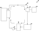
図1は、ペルフルオロヘプテンを含む作動流体を用いることにより、熱を有用な機械的動力に変換するための例示的なORCシステム10を示している。ORCシステム10は、閉鎖された作動流体ループ20を介して作動流体を循環させるため、第1の熱交換器40、膨張装置32、第2の熱交換器34、及びポンプ38又は圧縮機38を有する閉鎖された作動流体ループ20を含む。第1の熱交換器40は、ORCシステム10によって比較的低温の熱が捕捉され、シャフトをその長手方向軸周りに回転させるなどの有用な機械仕事に変換される低品質熱源46に直接熱接触してもよい。ORCシステムは、第2の熱交換器34の下流であって圧縮機38又はポンプ38の上流に、任意のサージタンク36を含んでもよい。
ORC system with improved working fluid Figure 1 shows an
熱エネルギーは、第1の熱交換器40を介して熱源46から作動流体サイクルに伝達される。加熱された作動流体は、第1の熱交換器40を出て、膨張装置32に入り、そこで膨張した作動流体のエネルギーの一部が機械仕事に変換される。例示的な膨張装置32は、タービンのようなターボ若しくは動的膨張器、又はスクリュー膨張機、スクロール膨張機、ピストン膨張機、及び回転翼膨張機などの容積流量膨張機を含んでもよい。膨張装置を出た膨張及び冷却された作動流体は、第2の熱交換器34に入り、更に冷却される。ポンプ38又は圧縮機38は、第2の熱交換器34の下流及び第1の熱交換器40の上流に位置し、ORCシステム10を介して作動流体を循環させてプロセスを繰り返す。
Thermal energy is transferred from the
回転シャフトは、所望の速度及び必要なトルクに依存して、ベルト、プーリー、ギア、トランスミッション、又は類似の装置の従来の構成を採用することによって任意の機械仕事を行うために使用することができる。回転シャフトは、誘電発電機などの発電装置30に接続されてもよい。生成される電気は、局所的に用いてもよく、グリッドに送達してもよい。
The rotating shaft can be used to perform any mechanical work by adopting conventional configurations of belts, pulleys, gears, transmissions, or similar devices, depending on the desired speed and required torque. .. The rotary shaft may be connected to a
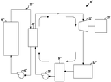
図2は、二次熱交換ループ25’を有するORCシステムを示している。二次熱交換ループ25’は、遠隔源46’から供給熱交換器40’に熱エネルギーを搬送するために使用され得る。遠隔熱源46’からの熱は、二次熱交換器ループ25’を介して循環する伝熱媒体を使用して、供給熱交換器40’に移送される。伝熱媒体は、熱供給熱交換器40’からポンプ42’まで流れ、ポンプによって伝熱媒体は熱源46’まで戻されてサイクルが繰り返される。この構成は、遠隔熱源から熱を除去し、ORCシステム10’に熱を送達する別の手段を提供する。二次熱交換ループ25’の供給熱交換器40’は、図1のORCシステム10の熱交換器40と同じであってもよいが、二次熱交換ループ25’の伝熱媒体は、ORCシステム10’の作動流体と非接触的に熱連通する。換言すれば、熱は、二次ループ25’の伝熱媒体からORCシステム10’の作動流体に伝達されるが、二次ループの伝熱媒体は、ORCシステム10’の作動流体と混じり合わない。この構成は、二次ループ及びORCシステムで使用するための様々な流体の使用を容易にすることによって可撓性をもたらす。
FIG. 2 shows an ORC system with a secondary heat exchange loop 25'. The secondary heat exchange loop 25'can be used to transfer heat energy from the remote source 46' to the supply heat exchanger 40'. The heat from the remote heat source 46'is transferred to the supply heat exchanger 40'using a heat transfer medium that circulates through the secondary heat exchanger loop 25'. The heat transfer medium flows from the heat supply heat exchanger 40'to the pump 42', and the heat transfer medium is returned to the heat source 46'by the pump, and the cycle is repeated. This configuration provides another means of removing heat from a remote heat source and delivering heat to the ORC system 10'. The supply heat exchanger 40'of the secondary heat exchange loop 25'may be the same as the
ペルフルオロヘプテンを含む作動流体はまた、二次熱交換ループ流体として使用することができるが、ただし、ループ内の圧力は、ループ内の作動流体の温度において流体の飽和圧以上に維持される。あるいは、ペルフルオロヘプテンを含む作動流体は、熱交換システムで作動流体を蒸発させて、流量を維持するのに十分大きな流体密度差を生じさせる(熱サイホン効果)動作モードで、熱源から熱を抽出するための二次熱交換ループ流体又は熱媒体流体として使用されてもよい。更に、グリコール、ブライン、シリコーン、又は他の本質的に不揮発性の流体などの高沸点流体は、二次ループ構成において顕熱伝達用に使用されてもよい。 The working fluid containing perfluoroheptene can also be used as a secondary heat exchange loop fluid, provided that the pressure in the loop is maintained above the saturation pressure of the fluid at the temperature of the working fluid in the loop. Alternatively, the working fluid containing perfluoroheptene extracts heat from the heat source in a mode of operation in which the working fluid evaporates in the heat exchange system, creating a fluid density difference large enough to maintain the flow rate (heat siphon effect). May be used as a secondary heat exchange loop fluid or heat transfer fluid. In addition, high boiling fluids such as glycols, brines, silicones, or other essentially non-volatile fluids may be used for heat transfer in secondary loop configurations.
ペルフルオロヘプテン(Perfluroheptene)を含む作動流体
高圧蒸気駆動(無機)動力サイクルの温度に比べて比較的低温で使用可能な熱を使用して、有機ランキン動力サイクルを介した機械仕事を発生させることができる。ペルフルオロヘプテンを含む作動流体の使用により、動力サイクルは、HFC-245faなどの既知の現在の作動流体の臨界温度より高い温度で、蒸発を介して熱エネルギーを受けることができ、それにより、より高いサイクルエネルギー効率をもたらし得る。「HFC-245fa」は、その化学名1,1,1,3,3-ペンタフルオロプロパンでも知られ、HoneywellからEnovate(登録商標)及びGenetron(登録商標)という商標名で市販されている。ペルフルオロヘプテンとしては、2-ペルフルオロヘプテン(CF3CF2CF2CF2CF=CFCF3)及び3-ペルフルオロヘプテン(CF3CF2CF2CF=CFCF2CF3)が挙げられ得、Chemours Company,LLCから入手可能である。ペルフルオロヘプテンは、参照によりその全体が本明細書に組み込まれている、米国特許第5,347,058号に開示されているように、フッ素化オレフィンを製造するためのプロセスにより製造され得る。
Working fluid containing Perfluroheptene The heat available at a relatively low temperature compared to the temperature of a high pressure steam driven (inorganic) power cycle can be used to generate mechanical work through an organic Rankin power cycle. can. The use of working fluids containing perfluoroheptene allows the power cycle to receive thermal energy through evaporation at temperatures above the critical temperature of known current working fluids such as HFC-245fa, thereby making it more. Can result in high cycle energy efficiency. "HFC-245fa" is also known by its chemical name 1,1,1,3,3-pentafluoropropane and is commercially available from Honeywell under the trade names Enovate® and Genetron®. Perfluoroheptene may include 2-perfluoroheptene (CF 3 CF 2 CF 2 CF 2 CF = CF CF 3 ) and 3-perfluorohepten (CF 3 CF 2 CF 2 CF = CF CF 2 CF 3 ). It is available from Chemours Company, LLC. Perfluoroheptene can be produced by a process for producing a fluorinated olefin, as disclosed in US Pat. No. 5,347,058, which is incorporated herein by reference in its entirety.
ペルフルオロヘプテンは、HFC-245faと比較した場合に、より高い臨界温度とより低い蒸気圧とを有し、より低いGWPを有することが期待される。ペルフルオロヘプテンを含む作動流体は、HFC-245faを含む作動流体を利用するように設計された既存のORCシステムにおいて、HFC-245faの直接交換物として使用されてもよい。作動流体は、2-ペルフルオロヘプテン、3-ペルフルオロヘプテン、又はそれらの組み合わせを含み得る。HFC-245faを含む作動流体を、2-ペルフルオロヘプテンと3-ペルフルオロヘプテンとの混合物を含む作動流体と交換すると、ORCシステムのサイクル効率を上げつつ(例えば、1.8%)一般に入手可能な商用機器構成部品(例えば、熱交換器)の最大設計圧力をかなり下回るレベルまで、蒸発器の熱交換器の動作圧力を低下させ、作動流体GWPを99.5%超低減させることができると予測される。 Perfluoroheptene is expected to have a higher critical temperature and lower vapor pressure and a lower GWP when compared to HFC-245fa. The working fluid containing perfluorohepten may be used as a direct replacement for HFC-245fa in existing ORC systems designed to utilize working fluids containing HFC-245fa. The working fluid may include 2-perfluoroheptene, 3-perfluoroheptene, or a combination thereof. Replacing the working fluid containing HFC-245fa with a working fluid containing a mixture of 2-perfluoroheptene and 3-perfluorohepten is generally available while increasing the cycle efficiency of the ORC system (eg, 1.8%). It is possible to reduce the operating pressure of the heat exchanger of the evaporator to a level well below the maximum design pressure of commercial equipment components (eg, heat exchangers) and reduce the working fluid GWP by more than 99.5%. is expected.
改善された作動流体は、2-ペルフルオロヘプテン及び3-ペルフルオロヘプテンからなる群から選択される少なくとも1種のペルフルオロヘプテンを含み得る。表1に示されているように、2-ペルフルオロヘプテン(20%)と3-ペルフルオロヘプテン(80%)(純度:99.20%)との混合物の臨界温度及び圧力は、それぞれ198℃及び1.54MPaである。この混合物の標準沸点は、72.5℃である。2-ペルフルオロヘプテンと3-ペルフルオロヘプテンとの混合物の臨界温度が高いほど、作動流体は、198℃に近づくより高い温度で、凝縮を介して熱を受けることが可能になる。 The improved working fluid may include at least one perfluoroheptene selected from the group consisting of 2-perfluoroheptene and 3-perfluoroheptene. As shown in Table 1, the critical temperature and pressure of the mixture of 2-perfluorohepten (20%) and 3-perfluorohepten (80%) (purity: 99.20%) are 198 ° C., respectively. And 1.54 MPa. The standard boiling point of this mixture is 72.5 ° C. The higher the critical temperature of the mixture of 2-perfluoroheptene and 3-perfluoroheptene, the higher the working fluid will be able to receive heat through condensation at higher temperatures approaching 198 ° C.
ペルフルオロヘプテンを含む作動流体は、ハイドロフルオロオレフィン(HFO)、ヒドロクロロフルオロオレフィン(HCFO)、ヒドロフルオロカーボン(HFC)、ヒドロフルオロエーテル(HFE)、ヒドロフルオロエーテルオレフィン(HFEO)、アルコール、エーテル、ケトン及び炭化水素(HC)からなる群から選択される少なくとも1つの化合物を更に含む。より具体的には、ペルフルオロヘプテンを含む作動流体は、Vertrel(登録商標)Sinera(商標)(Vertrel(登録商標)HFX-110としても知られる、Chemours Co.,Wilmington,Delaware,USAから入手可能なメチルペルフルオロヘプテンエーテル異性体の混合物である)、HFO-153-10mzzy、F22E、HFO-1438mzz(E)、HFO-1438mzz(Z)、HFO-1438ezy(Z)、HFO-1438ezy(E)、HFO-1336ze(Z)、HFO-1336ze(E)、HFO-1336mzz(Z)、HFO-1336mzz(E)、HFO-1234ze(E)、HFO-1234ze(Z)、HFO-1234yf、HCFO-1233zd(Z)、HCFO-1233zd(E)、HFC-43-10mee、HFC-365mfc、HFC-236ea、HFC-245fa、HFE-7000(HFE-347mcc又はn-C3F7OCH3としても知られる)、HFE-7100(HFE-449mccc又はC4F9OCH3としても知られる)、HFE-7200(HFE-569mccc又はC4F9OC2H5としても知られる)、HFE-7300(1,1,1,2,2,3,4,5,5,5-デカフルオロ-3-メトキシ-4-(トリフルオロメチル)-ペンタン又はC7H3F13Oとしても知られる)、HFE-7500(3-エトキシ-1,1,1,2,3,4,4,5,5,6,6,6-ドデカフルオロ-2-トリフルオロメチル-ヘキサン又は(CF3)2CFCF(OC2H5)CF2CF2CF3としても知られる)、ペンタン、ヘキサン、メタノール、エタノール、プロパノール、フルオリノール、ジメトキシメタン、ジメトキシエタン、及びジエトキシエタンからなる群から選択される少なくとも1つの成分を更に含み得る。HFE-7000、HFE-7100、HFE-7200、HFE-7300、及びHFE-7400は、3M(登録商標)からNovec(登録商標)Engineered Fluidsとして市販されている。 Working fluids containing perfluoroheptene are hydrofluoroolefins (HFOs), hydrochlorofluoroolefins (HCFOs), hydrofluorocarbons (HFCs), hydrofluoroethers (HFEs), hydrofluoroether olefins (HFEOs), alcohols, ethers, ketones. And at least one compound selected from the group consisting of hydrocarbons (HCs). More specifically, working fluids containing perfluoroheptene are available from Chemours Co., Wilmington, Delaware, USA, also known as Vertrel® Signera ™ (Vertrel® HFX-110). (A mixture of methylperfluoroheptene ether isomers), HFO-153-10mzzy, F22E, HFO-1438mzz (E), HFO-1438mzz (Z), HFO-1438ezy (Z), HFO-1438ezy (E), HFO-1336ze (Z), HFO-1336ze (E), HFO-1336mzz (Z), HFO-1336mzz (E), HFO-1234ze (E), HFO-1234ze (Z), HFO-1234yf, HCFO-1233zd ( Z), HCFO-1233zd (E), HFC-43-10mee, HFC-365mfc, HFC-236ea, HFC-245fa, HFE-7000 (also known as HFE-347mcc or n-C 3F 7 OCH 3 ), HFE-7100 (also known as HFE-449 mccc or C 4 F 9 OCH 3 ), HFE-7200 (also known as HFE-569 mccc or C 4 F 9 OC 2 H 5 ), HFE-7300 (1, 1, 1, 1,2,2,3,4,5,5-Decafluoro-3-methoxy-4- (trifluoromethyl) -pentane or C 7 H 3 F 13 O), HFE-7500 (also known as C 7 H 3 F 13 O), HFE-7500 ( 3-ethoxy-1,1,1,2,3,4,5,5,6,6,6-dodecafluoro-2-trifluoromethyl-hexane or (CF 3 ) 2 CFCF (OC 2 H 5 ) ) CF 2 CF 2 CF 3 ), which further comprises at least one component selected from the group consisting of pentans, hexanes, methanol, ethanol, propanols, fluorinols, dimethoxymethanes, dimethoxyethanes, and diethoxyethanes. obtain. HFE-7000, HFE-7100, HFE-7200, HFE-7300, and HFE-7400 are commercially available from 3M® as Novec® Engineered Fluids.
代替として、改善された作動流体は、2-ペルフルオロヘプテン、3-ペルフルオロヘプテン、及び2-ペルフルオロヘプテンと3-ペルフルオロヘプテンとの混合物からなる群から選択される少なくとも1つの成分からなり得る。また、別の代替として、作動流体組成物は、2-ペルフルオロヘプテンからなり得る。また、別の代替として、作動流体組成物は、3-ペルフルオロヘプテンからなり得る。また、別の代替として、作動流体組成物は、2-ペルフルオロヘプテンと3-ペルフルオロヘプテンとの混合物からなり得る。 Alternatively, the improved working fluid consists of at least one component selected from the group consisting of 2-perfluoroheptene, 3-perfluorohepten, and a mixture of 2-perfluorohepten and 3-perfluorohepten. obtain. Also, as another alternative, the working fluid composition may consist of 2-perfluoroheptene. Also, as another alternative, the working fluid composition may consist of 3-perfluoroheptene. Alternatively, the working fluid composition may consist of a mixture of 2-perfluoroheptene and 3-perfluoroheptene.
上に示されているように、2-ペルフルオロヘプテン(20%)と3-ペルフルオロヘプテン(80%)との混合物(純度:99.20%)の臨界温度は、198℃である。したがって、ペルフルオロヘプテンを含む作動流体は、HFC-245faを含む作動流体用に設計及び構成されているORCシステムが、より高い蒸発温度で熱を抽出し、HFC-245faを含む作動流体の場合より高いエネルギー効率を実現することを可能にする。既存のORCシステムにおけるHFC-245faを含む作動流体を、ペルフルオロヘプテンを含む作動流体と交換して、これらの既存のシステムの効率を上げることができる。 As shown above, the critical temperature of a mixture of 2-perfluorohepten (20%) and 3-perfluorohepten (80%) (purity: 99.20%) is 198 ° C. Therefore, the working fluid containing perfluoroheptene is more than the working fluid containing HFC-245fa, where the ORC system designed and configured for the working fluid containing HFC-245fa extracts heat at a higher evaporation temperature. It makes it possible to achieve high energy efficiency. The working fluid containing HFC-245fa in the existing ORC system can be replaced with the working fluid containing perfluorohepten to increase the efficiency of these existing systems.
亜臨界サイクル
一実施形態では、本発明は、ペルフルオロヘプテンを含む作動流体を使用して、亜臨界動力サイクルを使用することにより、熱を機械仕事へ変換するプロセスに関する。ORCシステムは、作動流体が作動流体の臨界圧より低い圧力で熱を受けた場合に亜臨界サイクルで作動し、作動流体は全サイクルにわたってその臨界圧未満に留まる。このプロセスは、(a)液体作動流体をその臨界圧未満の圧力に圧縮する工程と、(b)工程(a)の圧縮された液体作動流体を、熱源によって供給される熱を使用して加熱し、蒸気作動流体を形成する工程と、(c)膨張装置において工程(b)の蒸気作動流体を膨張させて機械仕事を発生させる工程と、(d)工程(c)の膨張した作動流体を冷却して、冷却された液体作動流体を形成する工程と、(e)工程(d)の冷却された液体作動流体を工程(a)へ循環させて、サイクルを繰り返す工程と、を含む。
Subcritical Cycle In one embodiment, the invention relates to a process of converting heat into mechanical work by using a subcritical power cycle using a working fluid containing perfluoroheptene. The ORC system operates in a subcritical cycle when the working fluid receives heat at a pressure lower than the critical pressure of the working fluid, and the working fluid remains below that critical pressure for the entire cycle. This process involves (a) compressing the liquid working fluid to a pressure below its critical pressure and (b) heating the compressed liquid working fluid of step (a) using the heat supplied by the heat source. The step of forming the steam working fluid, (c) the step of expanding the steam working fluid of step (b) to generate mechanical work in the expansion device, and (d) the step of expanding the working fluid of step (c). It includes a step of cooling to form a cooled liquid working fluid and a step of (e) circulating the cooled liquid working fluid of step (d) to step (a) and repeating the cycle.
亜臨界サイクルで動作する場合、ペルフルオロヘプテンを含む作動流体が熱源から熱を吸収する蒸発温度は、約100℃~約190℃、好ましくは約125℃~約185℃、より好ましくは約150℃~約185℃の範囲内である。亜臨界サイクルの典型的な膨張機の入口圧力は、臨界圧未満の約0.25MPa~約0.01MPaの範囲内である。亜臨界サイクルの典型的な膨張機の出口圧力は、約0.01MPa~約0.25MPa、より典型的には約0.04MPa~約0.12MPaの範囲内である。 When operating in a subcritical cycle, the evaporation temperature at which the working fluid containing perfluoroheptene absorbs heat from the heat source is from about 100 ° C to about 190 ° C, preferably from about 125 ° C to about 185 ° C, more preferably from about 150 ° C. It is in the range of about 185 ° C. The inlet pressure of a typical expander in a subcritical cycle is in the range of about 0.25 MPa to about 0.01 MPa below the critical pressure. The outlet pressure of a typical expander in a subcritical cycle is in the range of about 0.01 MPa to about 0.25 MPa, more typically about 0.04 MPa to about 0.12 MPa.
亜臨界サイクル動作の場合、作動流体に供給される熱の大部分は、作動流体の蒸発中に供給される。結果として、作動流体が単一の流体成分からなる場合、又は作動流体が擬似共沸の多成分流体混合物である場合、作動流体の温度は、熱源から作動流体への伝熱の間ずっと本質的に一定である。 In the case of subcritical cycle operation, most of the heat supplied to the working fluid is supplied during the evaporation of the working fluid. As a result, if the working fluid consists of a single fluid component, or if the working fluid is a quasi-co-boiling multi-component fluid mixture, the temperature of the working fluid is essential throughout the heat transfer from the heat source to the working fluid. Is constant.
遷移臨界ランキンサイクル
亜臨界サイクルと対照的に、流体をその臨界圧を超える圧力で相変化することなく等圧加熱したとき、作動流体の温度は変動し得る。したがって、熱源の温度が変動するとき、その臨界圧よりも高い圧力の流体を使用して熱源から熱を抽出することにより、亜臨界熱抽出の場合と比べて、熱源の温度と作動流体の温度とをより一致させることができる。その結果、超臨界サイクル又は遷移臨界サイクルにおける、温度が変動する熱源と、単一成分又は擬似共沸の作動流体との間の熱交換システムの効率は、多くの場合、亜臨界サイクルのものよりも高い(Chen et al,Energy,36,(2011)549~555及びその中における参照文献を参照されたい)。
Transition Critical Rankine Cycle In contrast to the subcritical cycle, the temperature of the working fluid can fluctuate when the fluid is isobarically heated at a pressure above its critical pressure without phase change. Therefore, when the temperature of the heat source fluctuates, the temperature of the heat source and the temperature of the working fluid are compared with the case of subcritical heat extraction by extracting heat from the heat source using a fluid having a pressure higher than the critical pressure. Can be more matched with. As a result, the efficiency of heat exchange systems between temperature-varying heat sources and single-component or quasi-azeotropic working fluids in supercritical or transitional critical cycles is often higher than in subcritical cycles. Also high (see Chen et al, Energy, 36, (2011) 549-555 and references therein).
別の実施形態では、本発明は、ペルフルオロヘプテンを含む作動流体を使用して、遷移臨界動力サイクルを使用することにより、熱エネルギーを機械仕事へ変換するプロセスに関する。ORCシステムは、作動流体が作動流体の臨界圧より高い圧力で熱を受ける場合に、遷移臨界サイクルとして動作する。遷移臨界サイクルでは、作動流体は、サイクル全体にわたってその臨界圧より高い圧力には留まらない。このプロセスは、(a)作動流体の臨界圧を超える圧力に液体作動流体を圧縮する工程と、(b)工程(a)の圧縮された作動流体を、熱源によって供給される熱を使用して加熱する工程と、(c)工程(b)の加熱された作動流体を膨張させて、作動流体の圧力をその臨界圧未満に低下させ、機械仕事を発生させる工程と、(d)工程(c)の膨張した作動流体を冷却して、冷却された液体作動流体を形成する工程と、(e)工程(d)の冷却された液体作動流体を工程(a)へ循環させて、サイクルを繰り返す工程と、を含む。 In another embodiment, the invention relates to a process of converting thermal energy into mechanical work by using a transition critical power cycle using a working fluid containing perfluoroheptene. The ORC system operates as a transition critical cycle when the working fluid receives heat at a pressure higher than the critical pressure of the working fluid. In a transitional critical cycle, the working fluid does not stay above its critical pressure throughout the cycle. This process uses the heat supplied by the heat source to (a) compress the liquid working fluid to a pressure above the critical pressure of the working fluid and (b) step (a) the compressed working fluid. A step of heating, a step of (c) expanding the heated working fluid of the step (b) to reduce the pressure of the working fluid to less than its critical pressure, and a step of generating mechanical work, and a step (d) (c). ) Is cooled to form a cooled liquid working fluid, and (e) the cooled liquid working fluid of step (d) is circulated to step (a), and the cycle is repeated. Including the process.
上述した遷移臨界動力サイクルシステムの第1の工程において、液相の作動流体は、その臨界圧を超えて圧縮される。第2の工程において、熱交換器が熱源と熱連通している膨張機に作動流体が入る前に、より高温に加熱される熱交換器に当該作動流体を通す。熱交換器は、熱伝達の任意の公知の手段によって熱源から熱エネルギーを受け取る。ORCシステムの作動流体は、熱供給熱交換器を循環し、そこで流体は熱を受け取る。 In the first step of the transition critical power cycle system described above, the working fluid of the liquid phase is compressed beyond its critical pressure. In the second step, the working fluid is passed through the heat exchanger, which is heated to a higher temperature, before the working fluid enters the expander in which the heat exchanger is in heat communication with the heat source. The heat exchanger receives heat energy from the heat source by any known means of heat transfer. The working fluid of the ORC system circulates in the heat supply heat exchanger, where the fluid receives heat.
次の工程において、加熱された作動流体の少なくとも一部が熱交換器から取り出され、膨張機に送られ、そこで流体膨張により、作動流体の熱エネルギー含量の少なくとも一部が、シャフトエネルギーなどの機械的エネルギーに変換される。作動流体の圧力を作動流体の臨界圧未満に低下させ、それによって蒸気相作動流体を生成する。 In the next step, at least a portion of the heated working fluid is removed from the heat exchanger and sent to the expander, where fluid expansion causes at least a portion of the thermal energy content of the working fluid to be mechanical, such as shaft energy. It is converted into target energy. The pressure of the working fluid is reduced below the critical pressure of the working fluid, thereby producing a vapor phase working fluid.
次の工程において、作動流体を膨張機から凝縮機に送り、蒸気相作動流体を凝縮させて液相作動流体を生成する。上記工程は、ループシステムを形成し、多数回繰り返してよい。 In the next step, the working fluid is sent from the expander to the condenser to condense the vapor phase working fluid to produce a liquid phase working fluid. The above steps may form a loop system and be repeated many times.
更に、遷移臨界動力サイクルについては、いくつかの異なる動作モードがある。1つの動作モードでは、遷移臨界動力サイクルの第1の工程において、作動流体は、当該作動流体の臨界圧よりも高い圧力に、実質的に等エントロピー的に圧縮される。次の工程において、作動流体は、実質的に一定圧力(等圧)条件下で、その臨界温度よりも高い温度に加熱される。次の工程において、作動流体を、当該作動流体を蒸気相で維持する温度で、実質的に等エントロピー的に膨張させる。膨張の終わりに、作動流体は、その臨界温度以下の温度の過熱蒸気である。このサイクルの最後の工程で、作動流体は冷却され、熱が冷却媒体へ放出されながら凝縮する。この工程中、作動流体は、液体に凝縮される。作動流体は、この冷却工程の最後に過冷却されてもよい。 In addition, there are several different modes of operation for transition critical power cycles. In one mode of operation, in the first step of the transition critical power cycle, the working fluid is compressed substantially isentropically to a pressure higher than the critical pressure of the working fluid. In the next step, the working fluid is heated to a temperature higher than its critical temperature under substantially constant pressure (isopressure) conditions. In the next step, the working fluid is expanded substantially isentropically at a temperature at which the working fluid is maintained in the vapor phase. At the end of expansion, the working fluid is a superheated steam at a temperature below its critical temperature. At the end of this cycle, the working fluid is cooled and the heat is released into the cooling medium and condensed. During this process, the working fluid is condensed into a liquid. The working fluid may be supercooled at the end of this cooling process.
遷移臨界ORC動力サイクルの別の動作モードでは、第1の工程において、作動流体を、当該作動流体の臨界圧よりも高い圧力に、実質的に等エントロピー的に圧縮する。次いで、次の工程において、作動流体は、実質的に一定圧力条件下で、その臨界温度よりも高い温度まで加熱されるが、加熱の程度は、次の工程において作動流体が実質的に等エントロピー的に膨張し、その温度が低下したときに、当該作動流体が、当該作動流体の部分的凝縮又はミスト化が起こり得る飽和蒸気に十分に近くなるような程度までだけである。しかし、この工程の終わりにおいて、作動流体は、依然としてわずかに過熱されている蒸気である。最後の工程で、作動流体は、冷却され、熱が冷却媒体へ放出されながら凝縮される。この工程中、作動流体は、液体に凝縮される。作動流体は、この冷却/凝縮工程の最後において過冷却されてもよい。 In another mode of operation of the transition critical ORC power cycle, in the first step, the working fluid is compressed substantially isoentropically to a pressure higher than the critical pressure of the working fluid. Then, in the next step, the working fluid is heated to a temperature higher than its critical temperature under substantially constant pressure conditions, but the degree of heating is such that the working fluid is substantially isentropic in the next step. Only to such an extent that the working fluid is sufficiently close to the saturated vapor at which partial condensation or mist formation of the working fluid can occur when it expands and its temperature drops. However, at the end of this process, the working fluid is still a slightly overheated steam. In the final step, the working fluid is cooled and condensed as heat is released to the cooling medium. During this process, the working fluid is condensed into a liquid. The working fluid may be supercooled at the end of this cooling / condensation process.
遷移臨界ORC動力サイクルの別の動作モードでは、第1の工程において、作動流体を、当該作動流体の臨界圧よりも高い圧力に、実質的に等エントロピー的に圧縮する。次の工程において、作動流体は、実質的に一定圧力条件下で、その臨界温度よりも低いか又はほんのわずかに高い温度まで加熱される。この段階では、作動流体の温度は、当該作動流体を次の工程で実質的に等エントロピー的に膨張させるとき、当該作動流体が部分的に凝縮するような温度である。最後の工程で、作動流体は、冷却され、熱が冷却媒体へ放出されながら完全に凝縮する。作動流体は、この工程の最後において過冷却されてもよい。 In another mode of operation of the transition critical ORC power cycle, in the first step, the working fluid is compressed substantially isoentropically to a pressure higher than the critical pressure of the working fluid. In the next step, the working fluid is heated to a temperature below or slightly above its critical temperature under substantially constant pressure conditions. At this stage, the temperature of the working fluid is such that the working fluid is partially condensed when it is expanded substantially isentropically in the next step. In the final step, the working fluid is cooled and completely condensed as heat is released to the cooling medium. The working fluid may be supercooled at the end of this step.
遷移臨界ORCサイクルの上記実施形態は、実質的に等エントロピー膨張及び圧縮、並びに実質的に等圧加熱又は冷却を示すが、このような等エントロピー的又は等圧条件が維持されないが、それにもかかわらず、サイクルが遂行される他のサイクルも、本発明の範囲内である。 The above embodiment of the transition critical ORC cycle exhibits substantially isentropic expansion and compression, as well as substantially isentropic heating or cooling, although such isentropic or isobaric conditions are not maintained. However, other cycles in which the cycle is carried out are also within the scope of the present invention.
典型的に遷移臨界ORCの場合、作動流体が熱源から熱を使用して加熱される温度は、約195℃~約300℃、好ましくは約200℃~約250℃、より好ましくは約200℃~225℃の範囲内である。遷移臨界サイクルの典型的な膨張機の入口圧力は、ほぼ臨界圧の1.79MPaから約7MPaまで、好ましくはほぼ臨界圧から約5MPaまで、より好ましくはほぼ臨界圧から約3MPaまでの範囲内である。遷移臨界サイクルの典型的な膨張機の出口圧力は、亜臨界サイクルのその圧力に相当する。 Typically in the case of transition critical ORC, the temperature at which the working fluid is heated using heat from a heat source is from about 195 ° C to about 300 ° C, preferably from about 200 ° C to about 250 ° C, more preferably from about 200 ° C. It is within the range of 225 ° C. Typical expander inlet pressures for transition critical cycles range from approximately critical pressures of 1.79 MPa to approximately 7 MPa, preferably approximately critical pressures to approximately 5 MPa, more preferably approximately critical pressures to approximately 3 MPa. be. The outlet pressure of a typical expander in a transition critical cycle corresponds to that pressure in a subcritical cycle.
超臨界ランキンサイクル
本発明の別の実施形態は、ペルフルオロヘプテンを含む作動流体を使用して、超臨界動力サイクルを使用することにより、熱エネルギーを機械仕事へ変換するプロセスに関する。ORCシステムは、サイクルで使用される作動流体が、サイクル全体にわたるその臨界圧よりも高い圧力にある場合に、超臨界サイクルとして動作する。超臨界ORCの作動流体は、亜臨界又は遷移臨界ORCのような別個の気液二相転移を通過しない。当該方法は、(a)作動流体をその臨界圧よりも高い圧力からより高い圧力に圧縮する工程と、(b)工程(a)の圧縮された作動流体を、熱源によって供給された熱を使用して加熱する工程と、(c)工程(b)の加熱された作動流体を膨張させて、作動流体の圧力をその臨界圧を超える圧力まで低下させ、機械仕事を発生させる工程と、(d)工程(c)の膨張した作動流体を冷却して、その臨界圧を超える冷却された作動流体を形成する工程と、(e)工程(d)の冷却された作動流体を工程(a)へ循環させて圧縮する工程と、を含む。
Supercritical Rankine Cycle Another embodiment of the invention relates to the process of converting thermal energy into mechanical work by using a supercritical power cycle using a working fluid containing perfluoroheptene. The ORC system operates as a supercritical cycle when the working fluid used in the cycle is at a pressure higher than its critical pressure throughout the cycle. The working fluid of a supercritical ORC does not pass through a separate gas-liquid two-phase transition such as a subcritical or transition critical ORC. The method uses (a) the step of compressing the working fluid from a pressure higher than its critical pressure to a higher pressure, and (b) the step (b) the compressed working fluid of step (a) using the heat supplied by the heat source. And heating, and (c) the step of expanding the heated working fluid of step (b) to reduce the pressure of the working fluid to a pressure exceeding the critical pressure, and the step of generating mechanical work, and (d). ) The step of cooling the expanded working fluid of the step (c) to form a cooled working fluid exceeding the critical pressure, and the step of (e) the cooled working fluid of the step (d) to the step (a). Includes a step of circulating and compressing.
典型的に超臨界サイクルの場合、作動流体が熱源から熱を使用して加熱される温度は、約190℃~約300℃、好ましくは約200℃~約250℃、より好ましくは約200℃~225℃の範囲内である。膨張機における作動流体の圧力は、膨張機の入口圧力から膨張機の出口圧力に向かって低下する。超臨界サイクルの典型的な膨張機の入口圧力は、約2MPa~約7MPa、好ましくは約2MPa~約5MPa、より好ましくは約3MPa~約4MPaの範囲内である。超臨界サイクルの典型的な膨張機の出口圧力は、臨界圧を超える約0.01MPa以内である。 Typically for supercritical cycles, the temperature at which the working fluid is heated using heat from a heat source is from about 190 ° C to about 300 ° C, preferably from about 200 ° C to about 250 ° C, more preferably from about 200 ° C to. It is within the range of 225 ° C. The pressure of the working fluid in the inflator decreases from the inflator inlet pressure to the inflator outlet pressure. The inlet pressure of a typical inflator in a supercritical cycle is in the range of about 2 MPa to about 7 MPa, preferably about 2 MPa to about 5 MPa, more preferably about 3 MPa to about 4 MPa. The outlet pressure of a typical expander in a supercritical cycle is within about 0.01 MPa above the critical pressure.
低品質熱源
本発明の新規な作動流体は、低圧蒸気、産業廃熱、太陽エネルギー、地熱温水、低圧地熱蒸気(一次又は二次機構)などの比較的低温の熱源、あるいは燃料電池、又はタービン、マイクロタービン、若しくは内燃機関などの原動機を利用する分散型発電装置から抽出されるか又は受け取られる熱から機械仕事を発生させるためのORCシステムにおいて使用することができる。1つの低圧蒸気源は、二流体地熱ランキンサイクルとして知られているシステムであってよい。多量の低温蒸気は、化石燃料動力発電所などの多くの場所で見出すことができる。
Low quality heat sources The novel working fluids of the present invention are relatively low temperature heat sources such as low pressure steam, industrial waste heat, solar energy, geothermal hot water, low pressure geothermal steam (primary or secondary mechanism), fuel cells, or turbines. It can be used in ORC systems to generate mechanical work from the heat extracted or received from a distributed power generator that utilizes a prime mover such as a microturbine or an internal combustion engine. One low pressure steam source may be a system known as the two-fluid geothermal Rankine cycle. Large amounts of cold steam can be found in many places, such as fossil fuel powered power plants.
他の熱源としては、移動内燃機関(例えばトラック若しくは鉄道又は船のディーゼルエンジン)から排出されるガスから回収される廃熱、固定内燃機関(例えば固定ディーゼルエンジン発電機)からの排気ガスからの廃熱、燃料電池からの廃熱、複合冷暖房発電又は地域冷暖房プラントにおいて利用可能な熱、バイオマス燃料のエンジンからの廃熱、バイオガス、埋立地ガス、及び炭層メタンなどの種々の供給源からのメタンで動作する、天然ガス若しくはメタンガスバーナー又はメタン燃焼ボイラー又はメタン燃料電池(例えば、分散発電施設)からの熱、紙/パルプ工場における樹皮及びリグニンの燃焼からの熱、焼却炉からの熱、(「ボトミング」ランキンサイクルを運転するための)従来のスチーム発電所における低圧蒸気からの熱、及び地熱を含む熱源が挙げられる。 Other heat sources include waste heat recovered from gas emitted from mobile internal combustion engines (eg, truck or railroad or ship diesel engines) and waste from exhaust gas from fixed internal combustion engines (eg, fixed diesel engine generators). Heat, waste heat from fuel cells, heat available in combined heating and cooling power plants or district heating and cooling plants, waste heat from biomass fuel engines, biogas, landfill gas, and methane from various sources such as coal seam methane. Heat from natural gas or methane gas burners or methane combustion boilers or methane fuel cells (eg, distributed power generation facilities) operating in, heat from the combustion of bark and lignin in paper / pulp factories, heat from incinerators, (" Examples include heat from low pressure steam in conventional steam power plants (for operating the "bottoming" Rankin cycle), as well as heat sources, including geothermal heat.
本発明のランキンサイクルの1つの実施形態では、地上を循環している作動流体に地熱を供給する(例えば、バイナリーサイクル地熱発電所)。本発明のランキンサイクルの別の実施形態では、本発明の新規な作動流体組成物は、ランキンサイクルの作動流体として、及び「熱サイホン効果」として知られている、温度誘導性の流体密度変動によって大規模又は排他的に生じる流れを有する深井戸の地下を循環する地熱媒体として使用される(例えば、Davis,A.P.and E.E.Michaelides:「Geothermal power production from abandoned oil wells」,Energy,34(2009)866~872;Matthews,H.B.U.S.Pat.No.4,142,108-Feb.27,1979を参照されたい)。 In one embodiment of the Rankine cycle of the present invention, geothermal heat is supplied to the working fluid circulating on the ground (eg, a binary cycle geothermal power plant). In another embodiment of the Rankine cycle of the invention, the novel working fluid composition of the invention is the working fluid of the Rankine cycle and by temperature-induced fluid density variation known as the "thermal siphon effect". It is used as a geothermal medium that circulates beneath deep wells with large or exclusively generated flows (eg, Davis, AP and E. E. Michaelides: "Geothermal power production from distributed oil wells", Energy. , 34 (2009) 866-872; Matthews, HBS Pat. No. 4,142, 108-Feb. 27, 1979).
他の熱源としては、パラボラソーラーパネルアレイなどのソーラーパネルアレイからの太陽熱、集中型太陽光発電所からの太陽熱、高PVシステム効率を維持するためにPVシステムを冷却するために光起電力(PV)ソーラーシステムから取り出された熱が挙げられる。 Other heat sources include solar heat from solar panel arrays such as parabolic solar panel arrays, solar heat from centralized photovoltaic power plants, and photovoltaics (PV) to cool PV systems to maintain high PV system efficiency. ) The heat extracted from the solar system can be mentioned.
他の実施形態では、本発明はまた、他の種類のORCシステム、例えば、マイクロタービン又は小型容積式膨張機を用いた小規模(例えば1~500kW、好ましくは5~250kW)ランキンサイクルシステム(例えば、Tahir,Yamada and Hoshino:「Efficiency of compact organic Rankine cycle system with rotary-vane-type expander for low-temperature waste heat recovery」,Intl J.of Civil and Environ.Eng 2:1 2010)、複合、多段階、及びカスケードランキンサイクル、並びに膨張機を出た蒸気からの熱を回収するための復熱器を有するランキンサイクルシステムを使用する。 In other embodiments, the invention also presents a small (eg, 1-500 kW, preferably 5-250 kW) Rankine cycle system (eg, eg, 1-500 kW, preferably 5-250 kW) using another type of ORC system, eg, a microturbine or a small positive displacement expander. , Tahir, Yamada and Hoshino: "Efficiency of compact organic Rankine cycle system with rotary-vane-type expander for low-temperature waste heat recovery", Intl J.of Civil and Environ.Eng 2: 1 2010), complex, multi-step , And a Cascade Rankine cycle, as well as a Rankine cycle system with a reheater to recover heat from the steam exiting the expander.
他の熱源としては、海運業、精油業者、石油化学プラント、オイル及びガスパイプライン、化学工業、商業ビル、ホテル、ショッピングモール、スーパーマーケット、ベーカリー、食品業界、レストラン、塗料硬化オーブン、家具製造、プラスチック成形業者、セメントキルン、材木キルン、焼成作業、鉄鋼業、硝子工業、鋳造所、製錬、空調、冷凍、及びセントラルヒーティングからなる群から選択される少なくとも1つの業界に関連する少なくとも1つの作業が挙げられる。 Other heat sources include shipping, oil refiners, petrochemical plants, oil and gas pipelines, chemical industry, commercial buildings, hotels, shopping malls, supermarkets, bakeries, food industry, restaurants, paint curing ovens, furniture manufacturing, plastic molding. At least one work related to at least one industry selected from the group consisting of traders, cement kilns, timber kilns, firing operations, steel industry, glass industry, foundries, smelting, air conditioning, freezing, and central heating. Can be mentioned.
本明細書に記述される概念について以下の実施例で更に説明するが、これは、特許請求の範囲に記載する本発明の範囲を限定するものではない。 The concepts described herein will be further described in the following examples, but this does not limit the scope of the invention described in the claims.
(実施例1).
作動流体としてHFC-245faを利用するORCシステムの予測サイクル効率を、作動流体として2-ペルフルオロヘプテンと3-ペルフルオロヘプテンとの混合物を利用するORCシステムの予測サイクル効率と比較した。ORCシステムの最大実現可能作動圧力は約3MPaであること、また、膨張機入口の作動流体のいずれかの温度を160℃に維持できる熱源が使用可能であることが想定された。
(Example 1).
The predicted cycle efficiency of the ORC system using HFC-245fa as the working fluid was compared with the predicted cycle efficiency of the ORC system using a mixture of 2-perfluoroheptene and 3-perfluorohepten as the working fluid. It was assumed that the maximum feasible working pressure of the ORC system was about 3 MPa and that a heat source capable of maintaining the temperature of any of the working fluids at the inlet of the expander at 160 ° C. could be used.
表1に、亜臨界サイクルで作動流体として利用されたHFC-245faと、20%の2-ペルフルオロヘプテン及び80%の3-ペルフルオロヘプテンを含む混合物(混合純度:99.20%)との比較表を示す。作動流体としてHFC-245faを使用するORCシステムの作動パラメータは、「HFC-245fa」というラベルの列に示されている。作動流体として2-ペルフルオロヘプテン/3-ペルフルオロヘプテンの混合物を使用するORCシステムの作動パラメータは、「2-ペルフルオロヘプテン/3-ペルフルオロヘプテン」というラベルの列に示されている。2-ペルフルオロヘプテン/3-ペルフルオロヘプテンの混合物の実験的に決定した蒸気圧を下の表1Aに示す。 Table 1 shows a mixture of HFC-245fa used as a working fluid in the subcritical cycle and a mixture containing 20% 2-perfluoroheptene and 80% 3-perfluorohepten (mixture purity: 99.20%). A comparison table is shown. The operating parameters of an ORC system using HFC-245fa as the working fluid are shown in the column labeled "HFC-245fa". The operating parameters of an ORC system using a mixture of 2-perfluoroheptene / 3-perfluorohepten as the working fluid are shown in the column labeled "2-perfluorohepten / 3-perfluorohepten". The experimentally determined vapor pressures of the mixture of 2-perfluoroheptene / 3-perfluorohepten are shown in Table 1A below.


上記実施例は、膨張機入口を160℃に維持するために熱を利用できることを想定している。HFC-245faを用いた蒸発温度は、蒸発器内の圧力が、CRCシステムに対して一般に利用可能な商用機器構成部品(例えば熱交換器)の最大許容設計作動圧力未満に留まることを保証にするため、145℃に制限した。 The above embodiment assumes that heat can be utilized to maintain the expander inlet at 160 ° C. Evaporation temperature with HFC-245fa ensures that the pressure in the evaporator remains below the maximum permissible design operating pressure of commercially available commercial equipment components (eg heat exchangers) generally available for CRC systems. Therefore, the temperature was limited to 145 ° C.
2-ペルフルオロヘプテン/3-ペルフルオロヘプテンの混合物を用いた蒸発圧力は、HFC-245faの蒸発圧力よりも十分低い圧力に留まるため、ORCシステムに対して一般に利用可能な商用機器の最大作動圧力も、HFC-245fa用に設計されたORCシステムに対して一部の管轄区域で必要とされる付加的な安全対策の圧力閾値も超過しない。更に、ペルフルオロヘプテン混合物は、これらの作動パラメータ内で許容される化学的安定性を示すことが期待される。 The evaporation pressure with the mixture of 2-perfluoroheptene / 3-perfluoroheptene remains well below the evaporation pressure of HFC-245fa, so the maximum working pressure of commercial equipment generally available for ORC systems. Also does not exceed the pressure threshold of additional safety measures required in some jurisdictions for ORC systems designed for HFC-245fa. In addition, the perfluoroheptene mixture is expected to exhibit acceptable chemical stability within these operating parameters.
上記の実施例は、2-ペルフルオロヘプテン/3-ペルフルオロヘプテンの混合物を使用すると、HFC-245faを作動流体として使用するように設計されたORCシステムで使用した場合、HFC-245faに比べて1.8%高いサイクル効率を実現しつつ、作動流体GWPを99.5%超低減し得ることを示している。既存のORCシステムにおけるHFC-245faを含む作動流体は、作動流体を排出させ、2-ペルフルオロヘプテン、3-ペルフルオロヘプテン、及びそれらの組み合わせからなる群から選択されるペルフルオロヘプテンを含む潤滑剤又は作動流体でORCシステムをフラッシングし、2-ペルフルオロヘプテン、3-ペルフルオロヘプテン、及びそれらの組み合わせからなる群から選択されるペルフルオロヘプテンを有する作動流体でORCシステムを充填することによって交換され得る。 The above examples use a mixture of 2-perfluoroheptene / 3-perfluoroheptene compared to HFC-245fa when used in an ORC system designed to use HFC-245fa as a working fluid. It shows that the working fluid GWP can be reduced by more than 99.5% while achieving a cycle efficiency of 1.8% higher. The working fluid containing HFC-245fa in the existing ORC system drains the working fluid and is a lubricant containing perfluoroheptene selected from the group consisting of 2-perfluoroheptene, 3-perfluoroheptene, and combinations thereof. Alternatively, the ORC system is replaced by flushing the ORC system with a working fluid and filling the ORC system with a working fluid having a perfluoroheptene selected from the group consisting of 2-perfluoroheptene, 3-perfluoroheptene, and combinations thereof. obtain.
(実施例2).
表2に、亜臨界サイクルの作動流体として及び遷移サイクルの作動流体として、利用される20%の2-ペルフルオロヘプテン及び80%の3-ペルフルオロヘプテンを含む混合物(混合純度:99.20%)の比較表を示す。膨張機入口温度は220℃に維持されている。
(Example 2).
Table 2 shows a mixture containing 20% 2-perfluoroheptene and 80% 3-perfluorohepten used as a working fluid for the subcritical cycle and as a working fluid for the transition cycle (mixture purity: 99.20%). ) Is shown in the comparison table. The expander inlet temperature is maintained at 220 ° C.

上の表は、膨張機の入口温度を220℃に維持することができる温度で熱を利用できる場合に、遷移臨界動作では、亜臨界動作の場合よりもサイクル熱効率及びサイクル容積がそれぞれ31.6%及び17.1%高くなることを示している。 The table above shows that when heat is available at a temperature that can maintain the inlet temperature of the expander at 220 ° C, the transition critical operation has a cycle thermal efficiency and cycle volume of 31.6, respectively, compared to the subcritical operation. It shows that it is higher by% and 17.1%.
本発明は、特に、その好ましい実施形態の観点から図示及び説明されているが、特許請求の範囲に記載されている本発明の趣旨及び範囲から逸脱することなく、詳細における様々な変更が成立し得ることが、当業者には理解される。 The present invention has been illustrated and described in particular in terms of preferred embodiments thereof, but various changes in detail have been made without departing from the spirit and scope of the invention described in the claims. What will be gained will be understood by those skilled in the art.
Claims (3)
(a) 作動流体の臨界圧を超える圧力に液体作動流体を圧縮して、圧縮された作動流体を形成する工程と、
(b) 前記圧縮された作動流体を、前記熱源によって供給される熱を使用して加熱して、加熱された作動流体を形成する工程と、
(c) 加熱された作動流体を膨張させて機械仕事を発生させ、前記作動流体の前記圧力をその臨界圧より低下させる工程と、
(d) 工程(c)の作動流体を冷却して、冷却された液体作動流体を形成する工程と、
(e) 工程(d)の冷却された液体作動流体を工程(a)に循環させて、前記サイクルを繰り返す工程と、
を含み、
前記作動流体が2-ペルフルオロヘプテンと3-ペルフルオロヘプテンとの混合物からなることを特徴とする、プロセス。 A process for converting heat into mechanical work in the transition critical organic Rankine cycle .
(A) A step of compressing the liquid working fluid to a pressure exceeding the critical pressure of the working fluid to form a compressed working fluid.
(B) A step of heating the compressed working fluid using the heat supplied by the heat source to form a heated working fluid.
(C) A step of expanding the heated working fluid to generate mechanical work and lowering the pressure of the working fluid below its critical pressure.
(D) A step of cooling the working fluid of the step (c) to form a cooled liquid working fluid, and
(E) A step of circulating the cooled liquid working fluid of the step (d) in the step (a) and repeating the cycle, and a step of repeating the cycle.
Including
A process comprising the working fluid consisting of a mixture of 2-perfluoroheptene and 3-perfluoroheptene .
(a)前記有機ランキンサイクルシステムからHFC-245faを含む前記作動流体を排出することと、
(b)2-ペルフルオロヘプテンと3-ペルフルオロヘプテンとの混合物からなる作動流体で前記ORCシステムを充填することと、
を含むことを特徴とする方法。 A method of exchanging the working fluid of an organic Rankine cycle system filled with a working fluid containing HFC-245fa.
(A) Discharging the working fluid containing HFC-245fa from the organic Rankine cycle system.
(B) Filling the ORC system with a working fluid consisting of a mixture of 2-perfluoroheptene and 3-perfluorohepten .
A method characterized by including.
Priority Applications (2)
| Application Number | Priority Date | Filing Date | Title |
|---|---|---|---|
| JP2021156648A JP2022023850A (en) | 2016-02-25 | 2021-09-27 | Use of perfluoroheptenes in power cycle systems |
| JP2023077230A JP2023090893A (en) | 2016-02-25 | 2023-05-09 | Use of perfluoroheptenes in power cycle systems |
Applications Claiming Priority (3)
| Application Number | Priority Date | Filing Date | Title |
|---|---|---|---|
| US201662299580P | 2016-02-25 | 2016-02-25 | |
| US62/299,580 | 2016-02-25 | ||
| PCT/US2017/019323 WO2017147400A1 (en) | 2016-02-25 | 2017-02-24 | Use of perfluoroheptenes in power cycle systems |
Related Child Applications (1)
| Application Number | Title | Priority Date | Filing Date |
|---|---|---|---|
| JP2021156648A Division JP2022023850A (en) | 2016-02-25 | 2021-09-27 | Use of perfluoroheptenes in power cycle systems |
Publications (3)
| Publication Number | Publication Date |
|---|---|
| JP2019512061A JP2019512061A (en) | 2019-05-09 |
| JP2019512061A5 JP2019512061A5 (en) | 2020-04-30 |
| JP6995050B2 true JP6995050B2 (en) | 2022-01-14 |
Family
ID=58231783
Family Applications (3)
| Application Number | Title | Priority Date | Filing Date |
|---|---|---|---|
| JP2018542190A Active JP6995050B2 (en) | 2016-02-25 | 2017-02-24 | Use of perfluoroheptene in power cycle systems |
| JP2021156648A Pending JP2022023850A (en) | 2016-02-25 | 2021-09-27 | Use of perfluoroheptenes in power cycle systems |
| JP2023077230A Pending JP2023090893A (en) | 2016-02-25 | 2023-05-09 | Use of perfluoroheptenes in power cycle systems |
Family Applications After (2)
| Application Number | Title | Priority Date | Filing Date |
|---|---|---|---|
| JP2021156648A Pending JP2022023850A (en) | 2016-02-25 | 2021-09-27 | Use of perfluoroheptenes in power cycle systems |
| JP2023077230A Pending JP2023090893A (en) | 2016-02-25 | 2023-05-09 | Use of perfluoroheptenes in power cycle systems |
Country Status (9)
| Country | Link |
|---|---|
| US (2) | US11220932B2 (en) |
| EP (1) | EP3420203A1 (en) |
| JP (3) | JP6995050B2 (en) |
| CN (1) | CN108699921B (en) |
| AU (2) | AU2017222606B2 (en) |
| BR (1) | BR112018015643B1 (en) |
| CA (1) | CA3014204C (en) |
| MX (1) | MX2022015424A (en) |
| WO (1) | WO2017147400A1 (en) |
Families Citing this family (16)
| Publication number | Priority date | Publication date | Assignee | Title |
|---|---|---|---|---|
| CA3014204C (en) * | 2016-02-25 | 2023-07-18 | The Chemours Company Fc, Llc | Use of perfluoroheptenes in power cycle systems |
| JP6941076B2 (en) * | 2018-06-05 | 2021-09-29 | 株式会社神戸製鋼所 | Power generation method |
| CN109813001B (en) * | 2019-01-21 | 2020-12-15 | 东营市浩瀚生化科技有限公司 | Method for using low-temperature geothermal fluid in lift-free mode and geothermal energy extraction device |
| WO2021086804A1 (en) * | 2019-10-28 | 2021-05-06 | The Chemours Company Fc, Llc | Heat transfer fluids for use in low temperature chiller applications |
| US11592009B2 (en) | 2021-04-02 | 2023-02-28 | Ice Thermal Harvesting, Llc | Systems and methods for generation of electrical power at a drilling rig |
| US11255315B1 (en) | 2021-04-02 | 2022-02-22 | Ice Thermal Harvesting, Llc | Controller for controlling generation of geothermal power in an organic Rankine cycle operation during hydrocarbon production |
| US11486370B2 (en) | 2021-04-02 | 2022-11-01 | Ice Thermal Harvesting, Llc | Modular mobile heat generation unit for generation of geothermal power in organic Rankine cycle operations |
| US11644015B2 (en) | 2021-04-02 | 2023-05-09 | Ice Thermal Harvesting, Llc | Systems and methods for generation of electrical power at a drilling rig |
| US11421663B1 (en) | 2021-04-02 | 2022-08-23 | Ice Thermal Harvesting, Llc | Systems and methods for generation of electrical power in an organic Rankine cycle operation |
| US11480074B1 (en) | 2021-04-02 | 2022-10-25 | Ice Thermal Harvesting, Llc | Systems and methods utilizing gas temperature as a power source |
| US11493029B2 (en) | 2021-04-02 | 2022-11-08 | Ice Thermal Harvesting, Llc | Systems and methods for generation of electrical power at a drilling rig |
| US11359576B1 (en) | 2021-04-02 | 2022-06-14 | Ice Thermal Harvesting, Llc | Systems and methods utilizing gas temperature as a power source |
| US11293414B1 (en) | 2021-04-02 | 2022-04-05 | Ice Thermal Harvesting, Llc | Systems and methods for generation of electrical power in an organic rankine cycle operation |
| WO2023027188A1 (en) * | 2021-08-27 | 2023-03-02 | セントラル硝子株式会社 | Solvent composition, cleaning agent, cleaning method, coating film-forming composition, method for producing substrate having coating film, and aerosol |
| WO2023027189A1 (en) * | 2021-08-27 | 2023-03-02 | セントラル硝子株式会社 | Azeotropic composition, pseudoazeotropic composition, composition, cleaning agent, solvent, aerosol, and heat transfer medium |
| WO2023096900A1 (en) * | 2021-11-23 | 2023-06-01 | The Chemours Company Fc, Llc | Azeotropic and azeotrope-like compositions of perfluoroheptene and fluoroethers and uses thereof |
Citations (3)
| Publication number | Priority date | Publication date | Assignee | Title |
|---|---|---|---|---|
| JP2012512991A (en) | 2008-12-19 | 2012-06-07 | イー・アイ・デュポン・ドウ・ヌムール・アンド・カンパニー | Absorption power cycle system |
| JP2014529033A (en) | 2011-08-19 | 2014-10-30 | イー・アイ・デュポン・ドウ・ヌムール・アンド・カンパニーE.I.Du Pont De Nemours And Company | Method and composition for organic Rankine cycle for generating mechanical energy from heat |
| WO2015077570A1 (en) | 2013-11-22 | 2015-05-28 | E. I. Du Pont De Nemours And Company | Compositions comprising tetrafluoropropene and tetrafluoroethane; their use in power cycles; and power cycle apparatus |
Family Cites Families (14)
| Publication number | Priority date | Publication date | Assignee | Title |
|---|---|---|---|---|
| GB1204119A (en) * | 1966-09-22 | 1970-09-03 | Nat Res Dev | Improvements in and relating to power generating systems |
| US3584457A (en) * | 1969-06-02 | 1971-06-15 | Cox Ass Edwin | External combustion power generating system |
| NZ183668A (en) | 1976-04-06 | 1979-04-26 | Sperry Rand Corp | Geothermal power plants; working fluid injected into deep well |
| US4926650A (en) * | 1988-05-18 | 1990-05-22 | Pennwalt Corporation | Refrigerant fluid and method of use |
| US5347058A (en) | 1993-12-07 | 1994-09-13 | E. I. Du Pont De Nemours And Company | Process for the production of fluorinated olefins |
| US5762817A (en) * | 1996-04-12 | 1998-06-09 | E. I. Du Pont De Nemours And Company | Decafluoropentane compositions |
| US7428816B2 (en) | 2004-07-16 | 2008-09-30 | Honeywell International Inc. | Working fluids for thermal energy conversion of waste heat from fuel cells using Rankine cycle systems |
| EP1983038A1 (en) * | 2007-04-18 | 2008-10-22 | Turboden S.r.l. | Turbo generator (orc) for applications at middle-low temperatures, using a fluid with azeotropic behaviour |
| US20130091843A1 (en) | 2008-12-05 | 2013-04-18 | Honeywell International Inc. | Fluoro olefin compounds useful as organic rankine cycle working fluids |
| TW201829721A (en) * | 2013-06-04 | 2018-08-16 | 美商杜邦股份有限公司 | Use of alkyl perfluoroalkene ethers and mixtures thereof in high temperature heat pumps |
| EP3084152B1 (en) | 2013-12-20 | 2023-05-31 | 3M Innovative Properties Company | Fluorinated olefins as working fluids and methods of using same |
| WO2015187413A1 (en) | 2014-06-03 | 2015-12-10 | The Chemours Company Fc, Llc | Passivation layer comprising a photocrosslinked fluoropolymer |
| CN104469160A (en) | 2014-12-19 | 2015-03-25 | 宇龙计算机通信科技(深圳)有限公司 | Image obtaining and processing method, system and terminal |
| CA3014204C (en) * | 2016-02-25 | 2023-07-18 | The Chemours Company Fc, Llc | Use of perfluoroheptenes in power cycle systems |
-
2017
- 2017-02-24 CA CA3014204A patent/CA3014204C/en active Active
- 2017-02-24 BR BR112018015643-4A patent/BR112018015643B1/en active IP Right Grant
- 2017-02-24 US US16/073,675 patent/US11220932B2/en active Active
- 2017-02-24 EP EP17709310.1A patent/EP3420203A1/en active Pending
- 2017-02-24 WO PCT/US2017/019323 patent/WO2017147400A1/en active Application Filing
- 2017-02-24 CN CN201780012986.6A patent/CN108699921B/en active Active
- 2017-02-24 JP JP2018542190A patent/JP6995050B2/en active Active
- 2017-02-24 AU AU2017222606A patent/AU2017222606B2/en active Active
-
2018
- 2018-07-27 MX MX2022015424A patent/MX2022015424A/en unknown
-
2021
- 2021-09-27 JP JP2021156648A patent/JP2022023850A/en active Pending
- 2021-12-07 US US17/544,827 patent/US11732618B2/en active Active
-
2022
- 2022-08-11 AU AU2022215233A patent/AU2022215233A1/en active Pending
-
2023
- 2023-05-09 JP JP2023077230A patent/JP2023090893A/en active Pending
Patent Citations (3)
| Publication number | Priority date | Publication date | Assignee | Title |
|---|---|---|---|---|
| JP2012512991A (en) | 2008-12-19 | 2012-06-07 | イー・アイ・デュポン・ドウ・ヌムール・アンド・カンパニー | Absorption power cycle system |
| JP2014529033A (en) | 2011-08-19 | 2014-10-30 | イー・アイ・デュポン・ドウ・ヌムール・アンド・カンパニーE.I.Du Pont De Nemours And Company | Method and composition for organic Rankine cycle for generating mechanical energy from heat |
| WO2015077570A1 (en) | 2013-11-22 | 2015-05-28 | E. I. Du Pont De Nemours And Company | Compositions comprising tetrafluoropropene and tetrafluoroethane; their use in power cycles; and power cycle apparatus |
Also Published As
| Publication number | Publication date |
|---|---|
| CN108699921B (en) | 2022-12-23 |
| BR112018015643A2 (en) | 2018-12-26 |
| AU2017222606A1 (en) | 2018-08-02 |
| US11732618B2 (en) | 2023-08-22 |
| US11220932B2 (en) | 2022-01-11 |
| CN108699921A (en) | 2018-10-23 |
| JP2023090893A (en) | 2023-06-29 |
| AU2022215233A1 (en) | 2022-09-01 |
| CA3014204C (en) | 2023-07-18 |
| WO2017147400A1 (en) | 2017-08-31 |
| BR112018015643B1 (en) | 2023-12-19 |
| US20200131943A1 (en) | 2020-04-30 |
| MX2022015424A (en) | 2023-01-11 |
| JP2022023850A (en) | 2022-02-08 |
| JP2019512061A (en) | 2019-05-09 |
| US20220090521A1 (en) | 2022-03-24 |
| CA3014204A1 (en) | 2017-08-31 |
| EP3420203A1 (en) | 2019-01-02 |
| AU2017222606B2 (en) | 2022-08-04 |
Similar Documents
| Publication | Publication Date | Title |
|---|---|---|
| JP6995050B2 (en) | Use of perfluoroheptene in power cycle systems | |
| JP6800942B2 (en) | Methods and compositions for the Organic Rankine cycle to generate mechanical energy from heat | |
| CN110821590B (en) | Use of HFO-153-10mzzy in power cycling | |
| US8166761B2 (en) | Method and system for generating power from a heat source | |
| JP2015503046A (en) | Use of a composition comprising 1,1,1,2,3-pentafluoropropane and optionally Z-1,1,1,4,4,4-hexafluoro-2-butene in a power cycle | |
| EP2995668A1 (en) | Use of compositions comprising e-1,1,1,4,4,5,5,5-octafluoro-2-pentene in power cycles | |
| US20180215979A1 (en) | Use of 1,3,3,4,4,4-hexafluoro-1-butene in power cycles | |
| Bajaj et al. | Organic Rankine Cycle and Its Working Fluid Selection—A Review | |
| TWI618792B (en) | Processes and compositions for organic rankine cycles for generating mechanical energy from heat |
Legal Events
| Date | Code | Title | Description |
|---|---|---|---|
| A621 | Written request for application examination |
Free format text: JAPANESE INTERMEDIATE CODE: A621 Effective date: 20200205 |
|
| A521 | Request for written amendment filed |
Free format text: JAPANESE INTERMEDIATE CODE: A523 Effective date: 20200319 |
|
| A977 | Report on retrieval |
Free format text: JAPANESE INTERMEDIATE CODE: A971007 Effective date: 20201224 |
|
| A131 | Notification of reasons for refusal |
Free format text: JAPANESE INTERMEDIATE CODE: A131 Effective date: 20210119 |
|
| A521 | Request for written amendment filed |
Free format text: JAPANESE INTERMEDIATE CODE: A523 Effective date: 20210419 |
|
| A02 | Decision of refusal |
Free format text: JAPANESE INTERMEDIATE CODE: A02 Effective date: 20210525 |
|
| A521 | Request for written amendment filed |
Free format text: JAPANESE INTERMEDIATE CODE: A523 Effective date: 20210927 |
|
| C60 | Trial request (containing other claim documents, opposition documents) |
Free format text: JAPANESE INTERMEDIATE CODE: C60 Effective date: 20210927 |
|
| A911 | Transfer to examiner for re-examination before appeal (zenchi) |
Free format text: JAPANESE INTERMEDIATE CODE: A911 Effective date: 20211005 |
|
| C21 | Notice of transfer of a case for reconsideration by examiners before appeal proceedings |
Free format text: JAPANESE INTERMEDIATE CODE: C21 Effective date: 20211012 |
|
| TRDD | Decision of grant or rejection written | ||
| A01 | Written decision to grant a patent or to grant a registration (utility model) |
Free format text: JAPANESE INTERMEDIATE CODE: A01 Effective date: 20211207 |
|
| A61 | First payment of annual fees (during grant procedure) |
Free format text: JAPANESE INTERMEDIATE CODE: A61 Effective date: 20211214 |
|
| R150 | Certificate of patent or registration of utility model |
Ref document number: 6995050 Country of ref document: JP Free format text: JAPANESE INTERMEDIATE CODE: R150 |