JP6994187B2 - Brazing device and brazing method - Google Patents
Brazing device and brazing method Download PDFInfo
- Publication number
- JP6994187B2 JP6994187B2 JP2017194842A JP2017194842A JP6994187B2 JP 6994187 B2 JP6994187 B2 JP 6994187B2 JP 2017194842 A JP2017194842 A JP 2017194842A JP 2017194842 A JP2017194842 A JP 2017194842A JP 6994187 B2 JP6994187 B2 JP 6994187B2
- Authority
- JP
- Japan
- Prior art keywords
- laser light
- temperature
- brazing
- irradiation
- brazed
- Prior art date
- Legal status (The legal status is an assumption and is not a legal conclusion. Google has not performed a legal analysis and makes no representation as to the accuracy of the status listed.)
- Active
Links
Images


Description
本発明は、ろう付装置及びろう付方法に関する。 The present invention relates to a brazing device and a brazing method.
近年、熱源にレーザを用いてろう付を行う装置が提案されている(例えば、特許文献1を参照)。熱源にレーザを用いたろう付装置の用途としては、例えば、自動車用のボディを構成する外板同士の接合が挙げられる。 In recent years, an apparatus for brazing using a laser as a heat source has been proposed (see, for example, Patent Document 1). Applications of the brazing device using a laser as a heat source include, for example, joining of outer plates constituting a body for an automobile.
熱源にレーザを用いたろう付装置では、ろう材が溶解する温度となるようにレーザ光の強度の調整が行われる。その調整は、例えば、自動車用ボディの外板に使われる高張力鋼板(ハイテン材とも呼ばれる)のような高温に耐える素材同士を接合する場合には、熱による素材の変質を憂慮する必要性に乏しいので粗調整で済ますことも可能である。しかし、例えば、切削工具等に用いられるダイヤモンドのような高温に耐えない素材を接合する場合には、熱による素材の変質を可及的に抑制するべく、高度な調整が必要とされる。 In a brazing device that uses a laser as a heat source, the intensity of the laser beam is adjusted so that the temperature is such that the brazing material melts. The adjustment is that when joining materials that can withstand high temperatures, such as high-strength steel plates (also called high-tensile steel) used for the outer panels of automobile bodies, it is necessary to be concerned about the deterioration of the materials due to heat. Since it is scarce, it is possible to make rough adjustments. However, when joining a material that cannot withstand high temperatures, such as diamond used for cutting tools, a high degree of adjustment is required in order to suppress deterioration of the material due to heat as much as possible.
そこで、レーザ光が照射される部位の温度を計測する温度計を併用し、当該温度計の指示値が設定値になるようにレーザ光の強度をPID制御(Proportional-Integral-Differential Control)することが考えられる。しかし、レーザ光は素材を局部的に加熱するものであるため、レーザ光の強度変化による照射箇所の温度変動が著しい。また、ろう材として使われるものには溶融温度が1000℃に達するものもあるため、生産性を考慮すると、常温から溶融温度への速やかな到達を可能にする必要がある。したがって、これらの要求をPID制御で実現するには、高度なゲイン調整が必要となるが、ゲインの設定値は接合する素材にも依存するため、PID制御を使ったレーザ光の強度調整は事実上、実現が困難であった。 Therefore, a thermometer that measures the temperature of the part irradiated with the laser beam is also used, and the intensity of the laser beam is PID controlled (Proportional-Integral-Differential Control) so that the indicated value of the thermometer becomes the set value. Can be considered. However, since the laser beam locally heats the material, the temperature fluctuation of the irradiated portion due to the change in the intensity of the laser beam is remarkable. Further, since some of the brazing materials used have a melting temperature of 1000 ° C., it is necessary to enable the rapid arrival of the melting temperature from the normal temperature in consideration of productivity. Therefore, in order to realize these requirements by PID control, advanced gain adjustment is required, but since the gain setting value depends on the material to be joined, it is a fact that the intensity of the laser beam is adjusted by PID control. Above, it was difficult to realize.
そこで、本発明は、ろう付の熱源として用いられるレーザ光の照射箇所の温度制御を可能にする技術を提供する。 Therefore, the present invention provides a technique that enables temperature control of an irradiation point of a laser beam used as a heat source for brazing.
上記課題を解決するため、本発明では、温度測定手段によって得られるろう付対象の部材の温度の測定値に応じてレーザ光の照射と非照射が行われるようにレーザ光源を制御することにした。 In order to solve the above problems, in the present invention, it is decided to control the laser light source so that the laser light is irradiated and the laser light is not irradiated according to the measured value of the temperature of the member to be waxed obtained by the temperature measuring means. ..
詳細には、本発明は、ろう付装置であって、ろう付対象の部材に照射するレーザ光を出射するレーザ光源と、ろう付対象の部材の温度を測定する温度測定手段と、温度測定手段によって得られるろう付対象の部材の温度の測定値に応じてレーザ光の照射と非照射が行われるようにレーザ光源を制御する制御手段と、を備える。 Specifically, the present invention is a brazing device, which is a laser light source that emits a laser beam that irradiates a member to be brazed, a temperature measuring means for measuring the temperature of the member to be brazed, and a temperature measuring means. It is provided with a control means for controlling the laser light source so that the laser beam is irradiated and the laser beam is not irradiated according to the measured value of the temperature of the member to be brazed obtained by the above method.
上記のろう付装置では、ろう付対象の部材の温度が温度測定手段で測定されており、レーザ光の照射と非照射が測定値に応じて行われるようにレーザ光源が制御される。よって、上記のろう付装置では、測定値が目標温度を上回ればレーザ光が非照射となり、測定値
が目標温度を下回ればレーザ光が照射される。したがって、上記のろう付装置では、例えば、測定値が目標温度を大幅に下回っている加熱初期の段階においてはレーザ光の連続的な照射が行われ、ろう付対象の部材が速やかに昇温される。また、例えば、測定値が目標温度の付近にある場合は、レーザ光の照射と非照射が繰り返され、或いは、レーザ光の非照射状態が継続されることにより、ろう付対象の部材が適正な温度に維持される。
In the above brazing device, the temperature of the member to be brazed is measured by the temperature measuring means, and the laser light source is controlled so that the irradiation and non-irradiation of the laser beam are performed according to the measured values. Therefore, in the above brazing device, the laser beam is not irradiated when the measured value exceeds the target temperature, and the laser beam is irradiated when the measured value is below the target temperature. Therefore, in the above brazing device, for example, continuous irradiation of laser light is performed in the initial stage of heating when the measured value is significantly lower than the target temperature, and the temperature of the member to be brazed is rapidly raised. To. Further, for example, when the measured value is near the target temperature, the member to be brazed is appropriate by repeating the irradiation and non-irradiation of the laser beam or by continuing the non-irradiation state of the laser beam. Maintained at temperature.
すなわち、上記のろう付装置においては、レーザ光の強度を制御するのではなく、測定値に応じたレーザ光の照射と非照射の切り替えにより、ろう付対象の部材を適正な温度に維持することにしている。よって、上記のろう付装置では、光の強度に応じて著しい温度変化を招きやすいレーザ光を使ったろう付において、例えば、PID制御におけるゲインの設定ミス等に起因する過度な強度のレーザ光の照射といった著しく不安定な温度変動を与える要素もなく、安定的な温度制御が可能である。 That is, in the above brazing device, instead of controlling the intensity of the laser beam, the member to be brazed is maintained at an appropriate temperature by switching between irradiation and non-irradiation of the laser beam according to the measured value. I have to. Therefore, in the above-mentioned brazing device, in brazing using a laser beam that tends to cause a significant temperature change depending on the light intensity, for example, irradiation of an excessive intensity laser beam due to a gain setting error in PID control or the like. Stable temperature control is possible without any factors that give remarkably unstable temperature fluctuations.
なお、制御手段は、ろう付対象の部材の温度の設定値を経過時間に応じて定めた設定情報を参照し、測定値が各経過時間で設定情報の定める設定値となるようにレーザ光源を制御するものであってもよい。また、設定情報には、レーザ光源が出射するレーザ光の強度が経過時間に応じて更に定められており、制御手段は、レーザ光源が出射するレーザ光の強度が各経過時間で設定情報の定める強度となるようにレーザ光源を制御するものであってもよい。また、設定情報には、ろう付対象の部材の性状が維持され且つろう材が溶融する温度が設定値として定められていてもよい。また、設定情報には、設定値がろう付対象の部材の種類毎に定められていてもよい。 The control means refers to the setting information in which the temperature setting value of the member to be brazed is set according to the elapsed time, and the laser light source is set so that the measured value becomes the setting value defined by the setting information in each elapsed time. It may be controlled. Further, in the setting information, the intensity of the laser light emitted from the laser light source is further determined according to the elapsed time, and in the control means, the intensity of the laser light emitted from the laser light source is determined by the setting information in each elapsed time. The laser light source may be controlled so as to have an intensity. Further, in the setting information, the temperature at which the properties of the member to be brazed are maintained and the brazing material melts may be set as a set value. Further, in the setting information, the set value may be set for each type of the member to be brazed.
上記のろう付装置がこのような制御手段を備えていれば、ろう付の際の条件を予め設定することが可能となり、例えば、ろう付対象の素材に応じたろう付を容易に行うことができる。 If the above brazing device is provided with such a control means, it is possible to set conditions for brazing in advance, and for example, brazing can be easily performed according to the material to be brazed. ..
また、上記のろう付装置は、ろう付対象の部材が格納される容器と、容器内を真空引きするポンプと、を更に備えるものであってもよい。ろう付が真空引きされた容器内で行われれば、ろう付対象の部材の酸化を抑制することができる。 Further, the brazing device may further include a container in which the member to be brazed is stored and a pump for evacuating the inside of the container. If brazing is performed in a vacuumed container, oxidation of the member to be brazed can be suppressed.
また、上記のろう付装置は、容器内へ不活性ガスを供給するガス供給手段を更に備えるものであってもよい。ろう付が行われる真空引きされた容器内に不活性ガスが供給されれば、真空引きが不足していてもろう付対象の部材の酸化を抑制することができ、且つ、ろう付対象の部材の冷却を速やかに行うことができる。 Further, the brazing device may further include a gas supply means for supplying the inert gas into the container. If the inert gas is supplied into the vacuumed container to be brazed, the oxidation of the member to be brazed can be suppressed even if the vacuum is insufficient, and the member to be brazed can be suppressed. Can be cooled quickly.
ところで、本発明は、方法の側面から捉えることもできる。例えば、本発明は、ろう付方法であって、レーザ光源から出射されるレーザ光をろう付対象の部材に照射する工程と、ろう付対象の部材の温度を測定する工程と、ろう付対象の部材の温度の測定値に応じてレーザ光の照射と非照射が行われるようにレーザ光源を制御する工程と、を有するものであってもよい。 By the way, the present invention can also be grasped from the aspect of the method. For example, the present invention is a brazing method, which comprises a step of irradiating a member to be brazed with a laser beam emitted from a laser light source, a step of measuring the temperature of the member to be brazed, and a step of measuring the temperature of the member to be brazed. It may have a step of controlling the laser light source so that the laser light is irradiated and the laser light is not irradiated according to the measured value of the temperature of the member.
上記のろう付装置及びろう付方法であれば、ろう付の熱源として用いられるレーザ光の照射箇所の温度制御を可能である。 With the above brazing device and brazing method, it is possible to control the temperature of the irradiation point of the laser beam used as the heat source for brazing.
以下、本発明の実施形態について説明する。以下に示す実施形態は、本発明の実施形態の一例であり、本発明の技術的範囲を以下の態様に限定するものではない。 Hereinafter, embodiments of the present invention will be described. The embodiments shown below are examples of embodiments of the present invention, and the technical scope of the present invention is not limited to the following embodiments.
図1は、ろう付装置1のシステム構成図である。ろう付装置1は、真空チャンバ2に格納された被加熱物をレーザ光照射装置3のレーザ光で加熱することにより、被加熱物のろう付を行う装置であり、真空チャンバ2やレーザ光照射装置3、その他の周辺機器を備える。すなわち、ろう付装置1は、被加熱物が格納される真空チャンバ2、被加熱物に照射するレーザ光を発生させるレーザ光照射装置3、真空チャンバ2に格納されている被加熱物の温度を測る放射温度計4、真空チャンバ2内を真空引きする真空排気ポンプ5、真空チャンバ2内へ不活性ガス(例えば、アルゴンガス)を供給するガスボンベ6、レーザ光照射装置3を制御するコントロールユニット7を備える。
FIG. 1 is a system configuration diagram of the
レーザ光照射装置3は、真空チャンバ2に格納されている被加熱物へ向けてレーザ光を出射するガルバノ駆動レーザ光出力ユニット32、ガルバノ駆動レーザ光出力ユニット32へ送るレーザ光を発振するレーザ発振器34、レーザ発振器34を冷却する冷却ユニット35、ガルバノ駆動レーザ光出力ユニット32やレーザ発振器34を制御するレーザ制御PC36、レーザ光の矩形波を生成するファンクションジェネレータ37を有する。ろう付装置1では後述するように放射温度計4を使ったフィードバック制御を行っているため、ファンクションジェネレータ37は、発振周波数が最小値に設定されており、デューティー比も最大値に設定されている。したがって、ファンクションジェネレータ37は、実質的に連続波(CW:continuous wave)を発振する。
The laser
ろう付装置1では、被加熱物が真空チャンバ2内へ格納された後、真空排気ポンプ5を使って真空チャンバ2内の真空引きが行われる。真空チャンバ2内は、例えば、ろう材等の被加熱物の酸化現象において支配的な役割を果たす酸素の濃度を測定可能なピラニー真空計によって測定される真空度が、レーザ光による加熱中に被加熱物が酸化しない程度の真空度となるように調整される。また、真空チャンバ2内には、ガスボンベ6から不活性ガスが適当な流量で供給される。そして、ろう付装置1では、レーザ発振器34や冷却ユニット35が起動されてレーザ光による加熱の準備が整うと、コントロールユニット7やレーザ制御PC36の制御信号に従ってガルバノ駆動レーザ光出力ユニット32やレーザ発振器34、ファンクションジェネレータ37が作動し、真空チャンバ2内の被加熱物へレーザ光が照射される。
In the
ろう付装置1の概要については以上の通りである。以下、ろう付装置1の詳細について説明する。
The outline of the
図2は、ろう付装置1の真空チャンバ2付近を示した図である。真空チャンバ2は、被加熱物が格納される筒状の容器21と、容器21を密閉する蓋22とを有する。蓋22には、真空チャンバ2の上方に設置されているガルバノ駆動レーザ光出力ユニット32から放たれるレーザ光を容器21内へ透過させるためのレーザ光照射窓23が設けられている。
FIG. 2 is a diagram showing the vicinity of the
容器21は、レーザ光による加熱中に位置ずれが生じることの無いよう、台座25に固定されている。また、容器21の側面には、加熱中の被加熱物を観察するための覗き窓24が設けられている。また、容器21の側面には、加熱中の被加熱物から放たれる熱放射を放射温度計4で感知可能にするための温度測定窓28が設けられている。また、容器21の側面には、容器21の内部と真空排気ポンプ5とを連通する排気管26が接続されている。また、容器21の側面には、容器21の内部とガスボンベ6とを連通するガス供給管27が接続されている。排気管26とガス供給管27の途中には流量調整弁や仕切弁が設けられている。
The
真空チャンバ2の上方に設置されているガルバノ駆動レーザ光出力ユニット32には、レーザ発振器34に繋がる光ファイバ31が接続されている。そして、ガルバノ駆動レーザ光出力ユニット32は、光ファイバ31を通じてレーザ発振器34から送られるレーザ光を真空チャンバ2へ出射する。ガルバノ駆動レーザ光出力ユニット32は、X軸とY軸に各々対応する2つのミラーの角度をモータで制御し、レーザヘッド33から真空チャンバ2へ向けて放たれるレーザ光の照射方向を調整する。ガルバノ駆動レーザ光出力ユニット32が調整するレーザ光の照射方向は、レーザ制御PC36から指示された照射パターンに沿うように調整される。レーザヘッド33から真空チャンバ2へ向けて放たれたレーザ光は、蓋22のレーザ光照射窓23を透過し、容器21に格納されている被加熱物に照射される。
An
図3は、真空チャンバ2の内部構造を示した第1の図である。また、図4は、真空チャンバ2の内部構造を示した第2の図である。容器21の内部には、被加熱物Pを載せる台座29が設けられている。そして、台座29に搭載されている被加熱物Pには、レーザ光照射装置3から出射されたレーザ光が、レーザ光照射窓23を通じて真上から投射される。台座29に搭載されている被加熱物Pの加熱状態は、容器21の側方から覗き窓24を通じて目視で観察することができる。また、台座29に搭載されている被加熱物Pの温度は、被加熱物Pから斜め上方に放たれる熱放射を、温度測定窓28を通じて放射温度計4で感知することにより測定することができる。
FIG. 3 is a first diagram showing the internal structure of the
以下、ろう付装置1を使ったろう付のプロセスについて説明する。図5は、ろう付装置1を使って行われるろう付のフローチャートを示した図である。
Hereinafter, the brazing process using the
ろう付装置1の使用に際しては、まず、加熱温度や加熱時間といった加熱時に参照されるプロファイルの設定が行われる(S101)。ステップS101で行われるプロファイルの設定は、コントロールユニット7の操作画面を通じて行われる。図6は、コントロールユニット7の操作画面の一例を示した図である。コントロールユニット7の操作画面には、加熱を開始した場合にろう付装置1で実行される各加熱工程におけるプロファイルが表示される。例えば、図6では、第1番目に行われる「工程1」において、レーザ発振器34の出力電圧が5.1V、被加熱物Pの温度設定が251℃の状態で100秒間維持される旨の設定がなされている様子が示されている。ステップS101で設定されるプロフ
ァイルは、加熱する被加熱物Pの材質や形状、作業者が有する知見、その他の各種情報に基づいて、設定操作を行う作業者らによって設定される。
When using the
また、ろう付装置1の使用に際しては、プロファイルの設定作業に前後して、容器21内に被加熱物Pがセットされる(S102)。被加熱物Pの接合部分には適宜のろう材が塗布されている。そして、容器21の開口部分が蓋22に閉鎖され、真空チャンバ2が密閉状態になる(S103)。なお、ろう材としては、例えば、金ろう、銀ろう、銅ろう、黄銅ろう、ニッケルろう、パラジウムろう等の適宜のろう材が挙げられる。また、被加熱物Pの部材としては、炭素鋼、合金鋼等の鉄鋼材料、タングステン、モリブデン等の非鉄金属材料、合金類、セラミックス、ダイヤモンド、その他、ろう材を介して互いに接合されるあらゆる異種素材同士の組み合わせを挙げることができる。
Further, when using the
真空チャンバ2が密閉された後は、真空排気ポンプ5が起動され、真空チャンバ2内の真空引きが行われる(S104)。そして、真空チャンバ2内の真空引きが完了した後は、レーザ光照射装置3の起動操作やガスボンベ6からの不活性ガスの供給開始操作が行われ、レーザ加熱の準備が整う(S105)。レーザ加熱の準備が整ったら、作業者は、コントロールユニット7等を操作して加熱を開始する(S106)。
After the
ステップS106で加熱開始操作が行われた場合にろう付装置1で実行される動作(S201~S209)の説明については後述することにし、先に加熱終了後のフローについて説明する。被加熱物Pの加熱が終了した後は(S107)、レーザ光照射装置3の停止操作やガスボンベ6からの不活性ガスの供給停止操作が行われる(S108)。また、真空排気ポンプ5が停止され、真空チャンバ2内の真空破壊が行われて真空チャンバ2内が大気圧にされる(S109)。真空チャンバ2内が大気圧になった後は、蓋22が外されて容器21の開口部分が開かれ、真空チャンバ2が開放される(S110)。真空チャンバ2が開放された後は、ろう付が完了した被加熱物Pの取り出しが行われる(S111)。
The operation (S201 to S209) executed by the
図7は、ろう付が完了した被加熱物Pの一例を示した図である。上記一連の処理(S101~S111)を経ることにより、母材に超硬材をろう付した被加熱物Pが完成する。 FIG. 7 is a diagram showing an example of the object to be heated P in which brazing is completed. By going through the above series of treatments (S101 to S111), the object to be heated P in which the cemented carbide is brazed to the base material is completed.
以下、ステップS106で加熱開始操作が行われた場合にろう付装置1で実行される動作(S201~S209)について説明する。
Hereinafter, the operations (S201 to S209) executed by the
ステップS106で加熱開始操作が行われると、コントロールユニット7において、工程数のカウンタ値(n)を1にセットする内部処理が行われる(S201)。そして、コントロールユニット7では、ステップS101で設定されたプロファイルの参照が行われ、第n番目の工程の温度設定値や出力電圧の設定値、キープ時間の設定値が読み出される(S202)。ステップS101に続けてステップS102が実行される場合、当該ステップS102では第1番目の工程の設定情報の読み出しが行われることになる。
When the heating start operation is performed in step S106, the
ステップS202の処理が行われた後は内部タイマーやレーザ発振器34が作動し、ステップS202で読み出された出力電圧の設定値でレーザ光が発振される。レーザ発振器34で発信されたレーザ光は、レーザヘッド33から出射され、レーザ光照射窓23を通じて被加熱物Pへ照射される(S203)。また、放射温度計4による被加熱物Pの温度測定が行われる。そして、被加熱物Pの温度が、ステップS202で読み出された温度設定値よりも所定値(α)だけ高い温度に達すると(S204)、レーザ発振器34によるレーザ光の発振が停止される(S205)。そして、被加熱物Pの温度が、ステップS202で読み出された温度設定値よりも所定値(α)だけ低い温度に達し(S206)、且つ、内部タイマーの経過時間がキープ時間の設定値を経過していなければ(S207)、
レーザ発振器34によるレーザ光の発振が再開される(S203)。また、内部タイマーの経過時間がキープ時間の設定値を経過した場合(S207)、ステップS101で設定されたプロファイルの参照が行われ、次工程の有無の判定が行われる(S208)。そして、ステップS208で肯定判定が行われれば、工程数のカウンタ値(n)が1カウント加算され(S209)、ステップS202以降の処理が再び実行される。また、ステップS208で否定判定が行われれば、既述したステップS107以降の処理が実行される。
After the processing in step S202 is performed, the internal timer and the
The oscillation of the laser beam by the
図8は、ろう付装置1において実現される被加熱物Pの温度とレーザ光の強度の変化の一例を示したグラフである。ろう付装置1では、上述したように、ステップS101で設定された各工程において、被加熱物Pの温度が温度設定値から所定値(α)の範囲内となるようにレーザ光の照射と非照射が繰り返される。よって、ろう付装置1では、図8に示すような被加熱物Pの温度とレーザ光の発振強度の変化が実現される。図8に示すグラフは、各工程の温度設定値や出力電圧の設定値、キープ時間の設定値が図6のように設定され、被加熱物Pの温度が温度設定値から1℃(すなわち、α=1)の範囲内となるようにレーザ光の照射と非照射が繰り返された場合の被加熱物Pの温度とレーザ光の発振強度の変化を示している。
FIG. 8 is a graph showing an example of changes in the temperature of the object to be heated P and the intensity of the laser beam realized in the
ろう付装置1では各工程において被加熱物Pの温度が温度設定値から所定値(α)の範囲内となるようにレーザ光の照射と非照射が繰り返されるため、被加熱物Pの温度が温度設定値よりも大幅に低い加熱開始初期においては、ステップS204で否定判定が継続され、図8のグラフにおいて「※1」で示されるように連続的なレーザ照射が行われる。そして、被加熱物Pの温度が温度設定値から所定値(α)の範囲内になると、図8のグラフにおいて「※2」で示されるようなパルス状のレーザ照射が行われたり、或いは、図8のグラフにおいて「※3」で示されるようなレーザ光の非照射状態が継続されたりする。レーザ光のパルス幅や間隔は、被加熱物Pの大きさやレーザ光の出力電圧、被加熱物Pから台座29への熱移動量、真空チャンバ2内にガスボンベ6から供給される不活性ガスの供給量等に応じて変化する。
In the
図8のグラフからも判るように、被加熱物Pの温度データに基づくフィードバック制御によって行われるレーザ光の照射および非照射の繰り返しにより、被加熱物Pの適正な温度制御を実現できることが判る。これは、コントロールユニット7に設定されたプロファイルに基づくレーザ光の照射と、真空チャンバ2内にガスボンベ6から供給される不活性ガスの供給による被加熱物Pの温度降下との相互作用によるものである。
As can be seen from the graph of FIG. 8, it can be seen that appropriate temperature control of the heated object P can be realized by repeating irradiation and non-irradiation of the laser beam performed by feedback control based on the temperature data of the heated object P. This is due to the interaction between the irradiation of the laser beam based on the profile set in the
図9は、温度制御を行わない比較例における被加熱物Pの温度とレーザ光の強度の変化の一例を示したグラフである。例えば、上記のろう付装置1においてステップS201からステップS209までの一連の処理が省略され、被加熱物Pの様子を監視しながらレーザ光の強度を徐々に上げて超硬材を母材にろう付する方法が採られる場合、図9のグラフに示されるように、被加熱物Pの温度は徐々に上昇し、レーザ光の強度はステップ状に上昇することになる。すなわち、温度制御を行わない比較例においては、超硬材が炭化しないように慎重な操作が行われることになる。よって、比較例においては、上記実施形態よりも多くの時間を費やすことになる。
FIG. 9 is a graph showing an example of changes in the temperature of the object to be heated P and the intensity of the laser beam in the comparative example in which the temperature is not controlled. For example, in the
また、上記実施形態のろう付装置1において、ガスボンベ6から真空チャンバ2内への不活性ガスの供給を停止した状態でろう付を試みたところ、ろう材の酸化が確認された。これは、真空チャンバ2内を真空引きする装置として現実的に選択可能なロータリーポンプを真空排気ポンプ5として用いたため、真空排気ポンプ5の排気能力の不足により真空チャンバ2内の酸素濃度が十分に低い値でなかった故である。また、上記実施形態のろう付装置1において、ガスボンベ6から真空チャンバ2内への不活性ガスの供給を停止した状態でろう付を試みたところ、加熱終了後の被加熱物Pの冷却に非常に長い時間がかかる
ことが判明した。これは、被加熱物Pの周囲を通過する不活性ガスの供給の停止により、真空の真空チャンバ2内に置かれている被加熱物Pが放熱されない故である。
Further, in the
上記実施形態のろう付装置1を用いて実際にろう付を行い、ろう付性を評価したので、その結果を以下に示す。
The
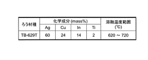
供試材料としては、母材に超硬合金(ISO使用分類K10相当材)を選択し、超硬材にPCD(多結晶ダイヤモンド)を選択した。図10は、試験片の形状および寸法を示した図である。試験片は、既製品を利用したため、切削工具のニアネットシェイプとなっている。PCDチップは、超硬合金が裏打ちされている一般的なものである。試験片の作製においては、ろう付面がPCDとなるようにした。これらの供試材はろう付前にアセトンで脱脂洗浄を行った。ろう材には東京ブレイズ株式会社製のペースト状の活性銀ろう「TB-629T」を使用した。TB-629Tの化学成分と溶融温度範囲を図11に示す。チップ側接合部全面に一定量のろう材を塗布後、超硬合金にセットし、約150℃でバインダーの乾燥を十分に施してから上記実施形態のろう付装置1でろう付を行った。
As the test material, cemented carbide (ISO use classification K10 equivalent material) was selected as the base material, and PCD (polycrystalline diamond) was selected as the cemented carbide. FIG. 10 is a diagram showing the shape and dimensions of the test piece. Since the test piece is an off-the-shelf product, it has a near-net shape for cutting tools. PCD chips are commonly lined with cemented carbide. In the preparation of the test piece, the brazed surface was set to PCD. These test materials were degreased and washed with acetone before brazing. As the brazing material, a paste-like active silver wax "TB-629T" manufactured by Tokyo Blaze Co., Ltd. was used. The chemical composition and melting temperature range of TB-629T are shown in FIG. After applying a certain amount of brazing material to the entire surface of the joint on the chip side, the material was set in cemented carbide, the binder was sufficiently dried at about 150 ° C., and then brazing was performed by the
本評価においては、真空チャンバ2内を1.5Paまで真空排気した後、排気を継続した状態で不活性ガスを導入し、真空チャンバ2内の圧力を1.5×10³Paにコントロールした状態でレーザ照射を行った。不活性ガスには高純度のAr(アルゴン)キャリアガスを用いた。ろう付温度は780℃で一定とし、保持時間を5秒、30秒、60秒と変化させた。図12は、レーザ照射位置、放射温度計の測定位置を示した図である。本評価では、PCDの周囲を周回しながら超硬合金が照射されるようにガルバノ駆動レーザ光出力ユニット32でレーザを円形状に描画し、500mm/秒の速度で移動させた。
In this evaluation, after the inside of the
また、本評価においては、比較のため、上記実施形態のろう付装置1ではない従来の一般的な真空炉による炉中ろう付試験片も作製した。ろう付条件は、炉内を1.0×10⁻¹Paまで真空排気後、排気を継続した状態で高純度のArキャリアガスを導入し、チャンバ内を約50Paにコントロールした。ろう付温度は、上記実施形態のろう付装置1を用いて試験片を作成した際と同じ780℃とし、保持時間を600秒とした。
In addition, in this evaluation, for comparison, a brazing test piece in a conventional general vacuum furnace, which is not the
図13は、本評価において作成した試験片の接合部分のSEM(Scanning Electron Microscope)像を示した図である。ろう付後のろう材層の厚さは、保持時間の経過に関わらず一定にはならなかった。レーザろう付と真空炉による炉中ろう付の何れの場合においても、ろう材の厚みのギャップコントロールを行っていないのがろう材層の厚さに影響したものと推測される。ろう材の凝固組織は、図13に示されるように、保持時間の増加に伴い粗大化していく傾向が見られた。 FIG. 13 is a diagram showing an SEM (Scanning Electron Microscope) image of the joint portion of the test piece prepared in this evaluation. The thickness of the brazed material layer after brazing did not become constant regardless of the passage of holding time. In both cases of laser brazing and in-furnace brazing, it is presumed that the fact that the gap control of the brazing thickness was not performed affected the thickness of the brazing material layer. As shown in FIG. 13, the solidified structure of the brazing material tended to become coarser as the holding time increased.
図14は、ろう付の保持時間と接合部のせん断強度の関係を示したグラフである。レーザろう付で接合した場合、保持時間が5秒の場合に184MPaと最高強度を示し、ろう付時間が長くなるに従い接合部の強度は低下した。また、上記実施形態のろう付装置1ではない従来の一般的な真空炉によるろう付で600秒間のろう付時間だった試験片に至っては、接合部の強度は107MPaまで低下した。
FIG. 14 is a graph showing the relationship between the holding time of brazing and the shear strength of the joint. When bonded by laser brazing, the maximum strength was 184 MPa when the holding time was 5 seconds, and the strength of the bonded portion decreased as the brazing time increased. Further, in the case of the test piece having a brazing time of 600 seconds by brazing with a conventional general vacuum furnace other than the
本検証により、上記実施形態のろう付装置1によって精密な温度管理を行い、極短時間のろう付保持時間でも十分に接合を実現できることが確認された。したがって、上記実施形態のろう付装置1であれば、熱影響の大きい部材に対する適正なろう付の実現が可能になると言える。
By this verification, it was confirmed that the
P・・被加熱物:1・・ろう付装置:2・・真空チャンバ:3・・レーザ光照射装置:4
・・放射温度計:5・・真空排気ポンプ:6・・ガスボンベ:7・・コントロールユニット:21・・容器:22・・蓋:23・・レーザ光照射窓:24・・覗き窓:25・・台座:26・・排気管:27・・ガス供給管:28・・温度測定窓:29・・台座:31・・光ファイバ:32・・ガルバノ駆動レーザ光出力ユニット:33・・レーザヘッド:34・・レーザ発振器:35・・冷却ユニット:36・・レーザ制御PC:37・・ファンクションジェネレータ
P ... Heated object: 1 ... Brazing device: 2 ... Vacuum chamber: 3 ... Laser light irradiation device: 4
・ ・ Radiation thermometer: 5 ・ ・ Vacuum exhaust pump: 6 ・ ・ Gas bomb: 7 ・ ・ Control unit: 21 ・ ・ Container: 22 ・ ・ Lid: 23 ・ ・ Laser light irradiation window: 24 ・ ・ Peep window: 25 ・・ Pedestal: 26 ・ ・ Exhaust pipe: 27 ・ ・ Gas supply pipe: 28 ・ ・ Temperature measurement window: 29 ・ ・ Pedestal: 31 ・ ・ Optical fiber: 32 ・ ・ Galvano drive laser light output unit: 33 ・ ・ Laser head: 34 ... Laser oscillator: 35 ... Cooling unit: 36 ... Laser control PC: 37 ... Function generator
Claims (6)
前記ろう付対象の部材の温度を測定する温度測定手段と、
前記温度測定手段によって得られる前記ろう付対象の部材の温度の測定値に応じてレーザ光の照射と非照射が行われるように前記レーザ光源を制御する制御手段と、を備え、
前記制御手段は、レーザ光の強度を温度の設定値の大きさに応じて定めた設定情報を参照し、レーザ光の照射と非照射の繰り返しにより前記ろう付対象の部材の温度を前記設定値にする際の照射時のレーザ光の強度が前記設定情報に従うように、前記レーザ光源を制御し、
前記設定情報には、前記設定値および前記レーザ光源が出射するレーザ光の強度が経過時間に応じて定められており、
前記制御手段は、前記設定情報を参照し、前記測定値が各経過時間で前記設定情報の定める設定値となり且つ前記レーザ光源が出射するレーザ光の強度が各経過時間で前記設定情報の定める強度となるように前記レーザ光源を制御する、
ろう付装置。 A laser light source that emits laser light that irradiates the member to be brazed,
A temperature measuring means for measuring the temperature of the member to be brazed, and
A control means for controlling the laser light source so that irradiation and non-irradiation of the laser beam are performed according to the measured value of the temperature of the member to be brazed obtained by the temperature measuring means is provided.
The control means refers to the setting information in which the intensity of the laser beam is determined according to the magnitude of the set value of the temperature, and the temperature of the member to be brazed is set to the set value by repeating irradiation and non-irradiation of the laser beam. The laser light source is controlled so that the intensity of the laser beam at the time of irradiation at the time of setting follows the setting information .
In the setting information, the set value and the intensity of the laser light emitted by the laser light source are determined according to the elapsed time.
The control means refers to the setting information, the measured value becomes the setting value defined by the setting information at each elapsed time, and the intensity of the laser light emitted by the laser light source is the intensity defined by the setting information at each elapsed time. The laser light source is controlled so as to
Brazing device.
請求項1に記載のろう付装置。 In the setting information, the temperature at which the properties of the member to be brazed are maintained and the brazing material melts is defined as the set value.
The brazing device according to claim 1 .
請求項1または2に記載のろう付装置。 In the setting information, the setting value is defined for each type of the member to be brazed.
The brazing device according to claim 1 or 2 .
前記容器内を真空引きするポンプと、を更に備える、
請求項1から3の何れか一項に記載のろう付装置。 A container in which the member to be brazed is stored and
Further equipped with a pump for evacuating the inside of the container.
The brazing device according to any one of claims 1 to 3 .
請求項4に記載のろう付装置。 Further provided with a gas supply means for supplying the inert gas into the container.
The brazing device according to claim 4 .
前記ろう付対象の部材の温度を測定する工程と、
前記ろう付対象の部材の温度の測定値に応じてレーザ光の照射と非照射が行われるように前記レーザ光源を制御する工程と、を有し、
前記レーザ光源を制御する工程では、レーザ光の強度を温度の設定値の大きさに応じて定めた設定情報を参照し、レーザ光の照射と非照射の繰り返しにより前記ろう付対象の部材の温度を前記設定値にする際の照射時のレーザ光の強度が前記設定情報に従うように、前記レーザ光源を制御し、
前記設定情報には、前記設定値および前記レーザ光源が出射するレーザ光の強度が経過時間に応じて定められており、
前記レーザ光源を制御する工程では、前記設定情報を参照し、前記測定値が各経過時間で前記設定情報の定める設定値となり且つ前記レーザ光源が出射するレーザ光の強度が各経過時間で前記設定情報の定める強度となるように前記レーザ光源を制御する、
ろう付方法。 The process of irradiating the member to be brazed with the laser light emitted from the laser light source, and
The process of measuring the temperature of the member to be brazed and
It has a step of controlling the laser light source so that irradiation and non-irradiation of the laser beam are performed according to the measured value of the temperature of the member to be brazed.
In the step of controlling the laser light source, the temperature of the member to be brazed is determined by repeating irradiation and non-irradiation of the laser light with reference to the setting information in which the intensity of the laser light is determined according to the magnitude of the set value of the temperature. The laser light source is controlled so that the intensity of the laser beam at the time of irradiation when the setting value is set to the setting value follows the setting information .
In the setting information, the set value and the intensity of the laser light emitted by the laser light source are determined according to the elapsed time.
In the step of controlling the laser light source, the setting information is referred to, the measured value becomes the set value defined by the setting information at each elapsed time, and the intensity of the laser light emitted from the laser light source is set at each elapsed time. The laser light source is controlled so as to have the intensity specified by the information.
Brazing method.
Priority Applications (1)
| Application Number | Priority Date | Filing Date | Title |
|---|---|---|---|
| JP2017194842A JP6994187B2 (en) | 2017-10-05 | 2017-10-05 | Brazing device and brazing method |
Applications Claiming Priority (1)
| Application Number | Priority Date | Filing Date | Title |
|---|---|---|---|
| JP2017194842A JP6994187B2 (en) | 2017-10-05 | 2017-10-05 | Brazing device and brazing method |
Publications (3)
| Publication Number | Publication Date |
|---|---|
| JP2019063852A JP2019063852A (en) | 2019-04-25 |
| JP2019063852A5 JP2019063852A5 (en) | 2020-08-06 |
| JP6994187B2 true JP6994187B2 (en) | 2022-01-14 |
Family
ID=66338809
Family Applications (1)
| Application Number | Title | Priority Date | Filing Date |
|---|---|---|---|
| JP2017194842A Active JP6994187B2 (en) | 2017-10-05 | 2017-10-05 | Brazing device and brazing method |
Country Status (1)
| Country | Link |
|---|---|
| JP (1) | JP6994187B2 (en) |
Families Citing this family (5)
| Publication number | Priority date | Publication date | Assignee | Title |
|---|---|---|---|---|
| JP6846449B2 (en) * | 2019-03-28 | 2021-03-24 | 株式会社ニューギン | Game machine |
| JP6846450B2 (en) * | 2019-03-28 | 2021-03-24 | 株式会社ニューギン | Game machine |
| JP6846447B2 (en) * | 2019-03-28 | 2021-03-24 | 株式会社ニューギン | Game machine |
| JP6846451B2 (en) * | 2019-03-28 | 2021-03-24 | 株式会社ニューギン | Game machine |
| JP6846453B2 (en) * | 2019-03-28 | 2021-03-24 | 株式会社ニューギン | Game machine |
Citations (3)
| Publication number | Priority date | Publication date | Assignee | Title |
|---|---|---|---|---|
| JP2005238301A (en) | 2004-02-27 | 2005-09-08 | Daihen Corp | Pulse arc welding method by irradiation with pulse laser |
| JP2006320961A (en) | 2005-04-19 | 2006-11-30 | Kagoshima Prefecture | Heat ray brazing device and heat ray brazing method |
| US20170144253A1 (en) | 2015-11-23 | 2017-05-25 | Nlight, Inc. | Fine-scale temporal control for laser material processing |
Family Cites Families (5)
| Publication number | Priority date | Publication date | Assignee | Title |
|---|---|---|---|---|
| JPS6360084A (en) * | 1986-08-29 | 1988-03-16 | Mitsubishi Electric Corp | Laser beam machine |
| JPS63248585A (en) * | 1987-04-03 | 1988-10-14 | Mitsubishi Electric Corp | Pulse laser machine |
| JPH06246478A (en) * | 1993-03-02 | 1994-09-06 | Techno Oote:Kk | Brazing device and brazing method by ion washing |
| JPH1098263A (en) * | 1996-09-20 | 1998-04-14 | Sony Corp | Soldering apparatus and method therefor |
| US9742196B1 (en) * | 2016-02-24 | 2017-08-22 | Doosan Fuel Cell America, Inc. | Fuel cell power plant cooling network integrated with a thermal hydraulic engine |
-
2017
- 2017-10-05 JP JP2017194842A patent/JP6994187B2/en active Active
Patent Citations (3)
| Publication number | Priority date | Publication date | Assignee | Title |
|---|---|---|---|---|
| JP2005238301A (en) | 2004-02-27 | 2005-09-08 | Daihen Corp | Pulse arc welding method by irradiation with pulse laser |
| JP2006320961A (en) | 2005-04-19 | 2006-11-30 | Kagoshima Prefecture | Heat ray brazing device and heat ray brazing method |
| US20170144253A1 (en) | 2015-11-23 | 2017-05-25 | Nlight, Inc. | Fine-scale temporal control for laser material processing |
Also Published As
| Publication number | Publication date |
|---|---|
| JP2019063852A (en) | 2019-04-25 |
Similar Documents
| Publication | Publication Date | Title |
|---|---|---|
| JP6994187B2 (en) | Brazing device and brazing method | |
| EP3450060B1 (en) | Lamination molding apparatus and method for manufacturing lamination molded product | |
| EP2961549B1 (en) | Apparatus and method for producing work pieces having a tailored microstructure | |
| EP1296796B1 (en) | Welding superalloy articles | |
| US9962787B2 (en) | Friction stir welding method, friction stir welding device and friction stir welded material | |
| EP3668679B1 (en) | Laser metal deposition of high gamma prime superalloys with cooling effect | |
| US20070095802A1 (en) | Laser treatment apparatus | |
| JP2014143304A (en) | Thermal bonding device and method of manufacturing thermally bonded product | |
| US6020571A (en) | Welding method and apparatus therefor | |
| JP2014140870A (en) | Heating joint device and manufacturing method for heating joint product | |
| US20180200838A1 (en) | Laser processing method | |
| JP4812172B2 (en) | R chamfering method using laser and laser processing head suitable for carrying out the method | |
| WO2017077829A1 (en) | Cubic boron nitride sintered body tool, cubic boron nitride sintered body used therein and production method for cubic boron nitride sintered body tool | |
| JP6325736B1 (en) | Manufacturing method of shaped objects | |
| US20070090097A1 (en) | Laser welding system for welding workpiece | |
| JP2020012160A (en) | Method for manufacturing laminate molded article | |
| KR102200515B1 (en) | Cutting Tool and Device for Brazing using Electron Beam and Method for Brazing using Electron Beam | |
| WO2020080425A1 (en) | Cured layer lamination method and production method for laminated molded article | |
| JP6763959B2 (en) | Chamber equipment, target generation method and extreme ultraviolet light generation equipment | |
| JPH07187836A (en) | Method for joining si-containing ceramics with laser light | |
| RU2269401C2 (en) | Method of laser welding of metals | |
| US20230321728A1 (en) | Additive manufacturing method | |
| JP2019111684A (en) | Method for producing molding | |
| JPH0417988A (en) | Cladding by laser welding method | |
| JP2003103382A (en) | Setting method for laser beam irradiation position |
Legal Events
| Date | Code | Title | Description |
|---|---|---|---|
| A621 | Written request for application examination |
Free format text: JAPANESE INTERMEDIATE CODE: A621 Effective date: 20200317 |
|
| A521 | Written amendment |
Free format text: JAPANESE INTERMEDIATE CODE: A523 Effective date: 20200625 |
|
| A131 | Notification of reasons for refusal |
Free format text: JAPANESE INTERMEDIATE CODE: A131 Effective date: 20210420 |
|
| A521 | Written amendment |
Free format text: JAPANESE INTERMEDIATE CODE: A523 Effective date: 20210618 |
|
| TRDD | Decision of grant or rejection written | ||
| A01 | Written decision to grant a patent or to grant a registration (utility model) |
Free format text: JAPANESE INTERMEDIATE CODE: A01 Effective date: 20211102 |
|
| A61 | First payment of annual fees (during grant procedure) |
Free format text: JAPANESE INTERMEDIATE CODE: A61 Effective date: 20211130 |
|
| R150 | Certificate of patent or registration of utility model |
Ref document number: 6994187 Country of ref document: JP Free format text: JAPANESE INTERMEDIATE CODE: R150 |