JP6993410B2 - Seismic structure - Google Patents
Seismic structure Download PDFInfo
- Publication number
- JP6993410B2 JP6993410B2 JP2019521441A JP2019521441A JP6993410B2 JP 6993410 B2 JP6993410 B2 JP 6993410B2 JP 2019521441 A JP2019521441 A JP 2019521441A JP 2019521441 A JP2019521441 A JP 2019521441A JP 6993410 B2 JP6993410 B2 JP 6993410B2
- Authority
- JP
- Japan
- Prior art keywords
- shield
- columns
- seismic
- pillar
- pillars
- Prior art date
- Legal status (The legal status is an assumption and is not a legal conclusion. Google has not performed a legal analysis and makes no representation as to the accuracy of the status listed.)
- Active
Links
- 239000000463 material Substances 0.000 claims description 47
- 239000004567 concrete Substances 0.000 claims description 31
- 230000000903 blocking effect Effects 0.000 description 52
- 239000002689 soil Substances 0.000 description 32
- 229910000831 Steel Inorganic materials 0.000 description 20
- 239000010959 steel Substances 0.000 description 20
- 230000000694 effects Effects 0.000 description 8
- 238000009412 basement excavation Methods 0.000 description 4
- 238000005553 drilling Methods 0.000 description 4
- 239000003415 peat Substances 0.000 description 4
- 230000000737 periodic effect Effects 0.000 description 4
- 239000011435 rock Substances 0.000 description 4
- 238000010586 diagram Methods 0.000 description 3
- 238000000034 method Methods 0.000 description 3
- 238000003491 array Methods 0.000 description 2
- 230000005540 biological transmission Effects 0.000 description 2
- 239000002131 composite material Substances 0.000 description 2
- 238000013016 damping Methods 0.000 description 2
- 239000006185 dispersion Substances 0.000 description 2
- 230000002093 peripheral effect Effects 0.000 description 2
- 230000001902 propagating effect Effects 0.000 description 2
- 239000004576 sand Substances 0.000 description 2
- -1 alluvium Substances 0.000 description 1
- 238000004873 anchoring Methods 0.000 description 1
- 238000013459 approach Methods 0.000 description 1
- 239000012620 biological material Substances 0.000 description 1
- 239000004568 cement Substances 0.000 description 1
- 239000004927 clay Substances 0.000 description 1
- 230000001066 destructive effect Effects 0.000 description 1
- 239000006260 foam Substances 0.000 description 1
- 239000000499 gel Substances 0.000 description 1
- 239000011440 grout Substances 0.000 description 1
- 238000009434 installation Methods 0.000 description 1
- 239000007788 liquid Substances 0.000 description 1
- 238000004519 manufacturing process Methods 0.000 description 1
- 239000000203 mixture Substances 0.000 description 1
- 239000004570 mortar (masonry) Substances 0.000 description 1
- 238000005457 optimization Methods 0.000 description 1
- 239000011148 porous material Substances 0.000 description 1
- 230000001681 protective effect Effects 0.000 description 1
- 239000008262 pumice Substances 0.000 description 1
- 238000001228 spectrum Methods 0.000 description 1
- 239000004575 stone Substances 0.000 description 1
- 239000000126 substance Substances 0.000 description 1
- 239000002023 wood Substances 0.000 description 1
Images
Classifications
-
- E—FIXED CONSTRUCTIONS
- E02—HYDRAULIC ENGINEERING; FOUNDATIONS; SOIL SHIFTING
- E02D—FOUNDATIONS; EXCAVATIONS; EMBANKMENTS; UNDERGROUND OR UNDERWATER STRUCTURES
- E02D31/00—Protective arrangements for foundations or foundation structures; Ground foundation measures for protecting the soil or the subsoil water, e.g. preventing or counteracting oil pollution
- E02D31/08—Protective arrangements for foundations or foundation structures; Ground foundation measures for protecting the soil or the subsoil water, e.g. preventing or counteracting oil pollution against transmission of vibrations or movements in the foundation soil
-
- E—FIXED CONSTRUCTIONS
- E02—HYDRAULIC ENGINEERING; FOUNDATIONS; SOIL SHIFTING
- E02D—FOUNDATIONS; EXCAVATIONS; EMBANKMENTS; UNDERGROUND OR UNDERWATER STRUCTURES
- E02D27/00—Foundations as substructures
- E02D27/32—Foundations for special purposes
- E02D27/34—Foundations for sinking or earthquake territories
-
- E—FIXED CONSTRUCTIONS
- E04—BUILDING
- E04H—BUILDINGS OR LIKE STRUCTURES FOR PARTICULAR PURPOSES; SWIMMING OR SPLASH BATHS OR POOLS; MASTS; FENCING; TENTS OR CANOPIES, IN GENERAL
- E04H9/00—Buildings, groups of buildings or shelters adapted to withstand or provide protection against abnormal external influences, e.g. war-like action, earthquake or extreme climate
- E04H9/02—Buildings, groups of buildings or shelters adapted to withstand or provide protection against abnormal external influences, e.g. war-like action, earthquake or extreme climate withstanding earthquake or sinking of ground
-
- G01V1/01—
Description
本発明は、防震構造に関し、特に、建物または建物群のために防震を提供する構造に関する。 The present invention relates to seismic structures, and in particular to structures that provide seismic protection for buildings or groups of buildings.
US Geological Surveyによれば、世界中で毎年3百万回を超える地震があり、大半はリヒタースケールでマグニチュード3.9以下であるが、900回を超える回数で5.0以上を計測している。小さな地震によって引き起こされる地上の振動であっても、建物の構造的完全性に対して影響を及ぼす。同様に、都市の鉄道網、地下鉄、杭打機などの機械、および道路からの侵入的な地上振動は、不動産価値または土地利用に対してしばしば影響を与える。地震波は、地上を通じて進行する表面波(レーリー波)、圧力波、およびせん断波から作られる。表面波は、損害の大部分をもたらし、最も遠くまで進行するが、体積波(圧力波およびせん断波)も、特に堆積盆地(sedimentary basins)において波がトラップする(wave trapping)場合、損害をもたらす。 According to the US Geological Survey, there are more than 3 million earthquakes worldwide each year, most of which have a magnitude of 3.9 or less on the Richter scale, but measure more than 5.0 with more than 900 earthquakes. Even ground vibrations caused by small earthquakes affect the structural integrity of the building. Similarly, intrusive ground vibrations from urban rail networks, subways, machines such as pile drivers, and roads often affect real estate value or land use. Seismic waves are made up of surface waves (Rayleigh waves), pressure waves, and shear waves that travel through the ground. Surface waves cause most of the damage and travel the farthest, but volumetric waves (pressure and shear waves) also cause damage, especially if the waves are trapping in the sedimentary basins. ..
地震波が建物に到達することを防止するために防護構造を提供することが望ましい。具体的には約1~10Hzの周波数の波が膨大な損害を引き起こし得る。なぜならば、そのような低周波数は、大きな距離を進行し、建物の共鳴基本周波数としばしば一致するためである。機械または近くの鉄道に起因する小さい大きさの地震波であっても、特に時間と共に、建物に著しい損害をもたらし得る。原子力発電所および石油精製所などの建物では、建物への小さい度合いの損害であっても壊滅的な結果をもたらし得る。 It is desirable to provide a protective structure to prevent seismic waves from reaching the building. Specifically, waves with a frequency of about 1-10 Hz can cause enormous damage. This is because such low frequencies travel large distances and often coincide with the building's resonant fundamental frequency. Even small seismic waves from machines or nearby railroads can cause significant damage to buildings, especially over time. In buildings such as nuclear power plants and oil refineries, even a small amount of damage to the building can have catastrophic consequences.
「Seismic metamaterial: how to shake friends and influence waves?」(S. Bruleら)では、地震試験が、約5mの深さ、320mmの直径、および、1.73mの間隔にある、空の円筒形の掘削孔の規則正しい正方形の格子において実施されている。試験は、格子の周期性によって引き起こされる伝達方向における地震波の相殺的干渉によって、約50Hzの地震波の地上を通る伝達が低減することを示した(これは、いわゆる部分的阻止帯域であり、つまり、特定の極性の弾性波が配列内で特定の結晶学的方向において伝播することができない周波数の範囲である)。 In "Seismic metamaterial: how to shake friends and influence waves?" (S. Brule et al.), A seismic test is conducted by excavating an empty cylinder at a depth of about 5 m, a diameter of 320 mm, and an interval of 1.73 m. It is carried out in a regular square grid of holes. Tests have shown that the offsetting interference of seismic waves in the direction of transmission caused by the periodicity of the lattice reduces the transmission of seismic waves through the ground at about 50 Hz (this is the so-called partial blocking band, ie. A range of frequencies in which elastic waves of a particular polarity cannot propagate in a particular crystallographic direction within the array).
「Artificial Seismic Shadow Zone by Acoustic Metamaterials」(Sang-Hoon KimおよびMukunda P. Das)および「Seismic Waveguide of Metamaterials」(Sang-Hoon KimおよびMukunda P. Das)では、地震波の共鳴周波数に対応する側孔を伴う巨大な空の箱(メタボックス)から成る防護が提案されている。多くのメタボックスから構成されたメタ障壁が地震波を減衰し、これは、地震エネルギーを消散させることにより波の振幅を飛躍的に低減する。これらのメタ障壁は、保護される建物の周りに地上に配置される。 In "Artificial Seismic Shadow Zone by Acoustic Metamaterials" (Sang-Hoon Kim and Mukunda P. Das) and "Seismic Waveguide of Metamaterials" (Sang-Hoon Kim and Mukunda P. Das), side holes corresponding to the resonance frequency of seismic waves are provided. Protection consisting of a huge empty box (metabox) with it has been proposed. A meta-barrier composed of many meta boxes attenuates seismic waves, which dramatically reduces the amplitude of the waves by dissipating the seismic energy. These meta-barriers are placed above the ground around the protected building.
「Possible Measures Of Taking-Over/ Dynamic Control Of Seismic Actions Applicable To Urban Utility Systems. Seismic Waves Deflection/ Damping Using Metamaterials」(Ungureanuら)は、建物のための地震の防護として、地震波の反射と、前述した方法(波を減衰するための周期的なパターンでの空の掘削孔、およびメタボックス)とを記載している。 "Possible Measures Of Taking-Over / Dynamic Control Of Seismic Actions Applicable To Urban Utility Systems. Seismic Waves Deflection / Damping Using Metamaterials" (Ungureanu et al.) (Empty drilling holes in a periodic pattern to attenuate waves, and metaboxes).
一態様において、本発明は、表土に埋め込まれ、岩盤と接触している柱のセットを備え、柱は、表土との材料差異を伴う材料から形成される、地震波シールドを提供する。このようなシールドは、より大きな範囲の周波数を網羅し、先行技術の空の掘削孔の配列における阻止帯域の下限周波数よりも低減された下限周波数を有する阻止帯域を生成することにより、地震波を反射する。シールドは、幅広いゼロ周波数バンドギャップを有する。阻止帯域内の周波数を有する地震波はシールドを通過することができない。先行技術よりも大きい本発明の阻止帯域の帯域幅は、柱と岩盤との間の接触と、表土(しばしば柔らかい土)と柱における材料との間での材料パラメータ(例えば、密度、ヤング率、体積弾性率、および/またはせん断弾性率)の不一致とに起因する。さらに、阻止帯域の下限は、柱と岩盤との間の接触に起因して、0Hzに近づいて、ゼロ周波数バンドギャップを作り出す。この接触は、柱を岩盤に効果的にピン留めまたは締め付けする。 In one aspect, the invention comprises a set of columns embedded in the topsoil and in contact with the bedrock, the columns providing a seismic shield made of a material with material differences from the topsoil. Such shields reflect seismic waves by covering a larger range of frequencies and creating a blocking band with a lower bound frequency that is lower than the lower bound frequency of the blocking band in the prior art array of empty drilling holes. do. The shield has a wide zero frequency bandgap. Seismic waves with frequencies within the blocking band cannot pass through the shield. The bandwidth of the blocking band of the present invention, which is larger than that of the prior art, is the contact between the pillar and the bedrock and the material parameters (eg, density, Young's modulus, etc.) between the surface soil (often soft soil) and the material in the pillar. Due to the mismatch of bulk modulus and / or shear modulus). In addition, the lower bound of the blocking band approaches 0 Hz due to the contact between the column and the bedrock, creating a zero frequency bandgap. This contact effectively pins or tightens the columns to the bedrock.
阻止帯域の帯域幅の増加、ゼロに近い周波数バンドギャップ、および上限周波数の上昇により、本発明は低周波数の地震波の大きな帯域を反射させることができる。したがって、阻止帯域は、最も遠くまで進行し、建物に最も大きな損害をもたらす周波数を網羅する。阻止帯域は、建物のほとんどの共鳴周波数も網羅する。効果は波動物理学によってもたらされるため、柱の塑性、配置、および形は、所望の阻止帯域を生成するために、波動物理学に従って選択され得る。 The increased bandwidth of the blocking band, the near-zero frequency bandgap, and the increase in the upper bound frequency allow the present invention to reflect large bands of low frequency seismic waves. Therefore, the blocking band covers the frequencies that travel the farthest and cause the greatest damage to the building. The blocking band also covers most resonance frequencies in the building. Since the effect is brought about by wave physics, the plasticity, placement, and shape of the columns can be selected according to wave physics to produce the desired blocking band.
空の掘削孔の方法を用いて約1~10Hzの周波数を網羅する阻止帯域を作り出すためには、穴は数メートルから数十メートルの直径を必要とする。地上に大きな穴を有することは、特に他の建物が近くにある領域では、明らかに実用的ではない。したがって、本発明は、先行技術の方法では達成できない実用的な手法で有用な阻止帯域を達成する。 To create a blocking band covering frequencies of about 1-10 Hz using the empty drilling hole method, the hole needs a diameter of a few meters to a few tens of meters. Having a large hole on the ground is clearly impractical, especially in areas where other buildings are nearby. Therefore, the present invention achieves a useful blocking band in a practical manner that cannot be achieved by prior art methods.
柱と表土との間の材料差異は、柱の材料の特性が表土の特性と異なるときに起こる。例えば、柱は、表土と異なる密度、ヤング率、せん断弾性率、または体積弾性率を有する可能性がある。2つ以上の特性が柱の材料と表土との間で異なる可能性がある。例えば、柱を形成する材料が、表土の材料と異なる密度および異なるヤング率を有する可能性がある。柱の材料は、剛体、液体、発泡体、またはゲルであり得る。 Material differences between columns and topsoil occur when the material properties of the columns differ from those of the topsoil. For example, columns can have a different density, Young's modulus, shear modulus, or bulk modulus than topsoil. Two or more properties can differ between the material of the column and the topsoil. For example, the material forming the column may have a different density and a different Young's modulus than the material of the topsoil. The material of the column can be rigid, liquid, foam, or gel.
材料差異は、表土より大きい密度を有する柱によって達成されてもよく、材料差異は、表土より大きいヤング率を有する柱によって達成されてもよく、材料差異は、表土より大きい体積弾性率を有する柱によって達成されてもよく、または、材料差異は、表土より大きいせん断弾性率を有する柱によって達成されてもよい。材料差異は、これらの条件のうちの2つ以上の組み合わせによって達成されてもよい。 Material differences may be achieved by columns with a density greater than the topsoil, material differences may be achieved by columns with a Young's modulus greater than the topsoil, and material differences may be achieved by columns with a bulk modulus greater than the topsoil. Or material differences may be achieved by columns with shear modulus greater than that of topsoil. Material differences may be achieved by a combination of two or more of these conditions.
材料差異は、表土の密度の少なくとも1.1倍の密度を有する柱によって達成されてもよく、材料差異は、表土のヤング率の少なくとも10倍のヤング率を有する柱によって達成されてもよく、材料差異は、表土の体積弾性率の少なくとも10倍の体積弾性率を有する柱によって達成されてもよく、または、材料差異は、表土のせん断弾性率の少なくとも10倍のせん断弾性率を有する柱によって達成されてもよい。材料差異は、これらの条件のうちの2つ以上の組み合わせによって達成されてもよい。土のヤング率は153MPaであってもよく、岩盤のヤング率は30GPaであってもよい。 Material differences may be achieved by columns having a Young's modulus of at least 1.1 times the density of the surface soil, and material differences may be achieved by columns having a Young's modulus of at least 10 times the Young's modulus of the surface soil. May be achieved by a column having a modulus of at least 10 times the modulus of volume of the surface soil, or material differences are achieved by a column having a modulus of elasticity at least 10 times the modulus of shear of the surface soil. May be. Material differences may be achieved by a combination of two or more of these conditions. The Young's modulus of soil may be 153 MPa, and the Young's modulus of bedrock may be 30 GPa.
柱は、表土より大きい密度を有し得る。柱は、表土の少なくとも1.1倍の密度であり得る。 Pillars can have a higher density than topsoil. Pillars can be at least 1.1 times as dense as topsoil.
表土の密度範囲は1600~2300kg/m3であり得、1800kg/m3であり得る(または、表土が泥炭である場合、密度は1200~1300kg/m3であり得る)。岩盤の密度は2500kg/m3であり得る。コンクリートから形成され得る柱の密度は2300~2500kg/m3であり得る。他の実施形態は、より大きい密度であり得る特別なコンクリート(重コンクリート)を使用してもよい。柱は表土の少なくとも1.1倍の密度であり得る。好ましくは、柱は表土の少なくとも1.4倍の密度であり得る。柱は、例えば柱が鋼鉄の杭(約7000kg/m3の密度)から形成されるとき、表土の少なくとも4倍の密度であり得る。 The density range of the topsoil can be 1600-2300 kg / m 3 and 1800 kg / m 3 (or if the topsoil is peat, the density can be 1200-1300 kg / m 3 ). The density of the bedrock can be 2500 kg / m 3 . The density of columns that can be formed from concrete can be 2300-2500 kg / m 3 . Other embodiments may use special concrete (heavy concrete), which can be of higher density. Pillars can be at least 1.1 times as dense as topsoil. Preferably, the columns can be at least 1.4 times as dense as the topsoil. The columns can be at least four times as dense as the topsoil, for example when the columns are formed from steel piles (density of about 7000 kg / m 3 ).
柱は表土より大きいヤング率を有し得る。柱のヤング率は、表土のヤング率より少なくとも10倍大きくし得る。 Pillars can have a Young's modulus greater than the topsoil. The Young's modulus of the pillar can be at least 10 times greater than the Young's modulus of the topsoil.
柱の各々の下部が岩盤に埋め込まれてもよい。これは、岩盤への柱のより効果的なピン留めを提供し、阻止帯域の下限周波数を低下させることにより、完全に、またはほとんど完全にゼロの周波数バンドギャップを作り出す。これは、このようなゼロ周波数バンドギャップを作り出すために阻止帯域の下限を低下させることが、より低い周波数の地震波が阻止され得ることを意味するため、有利である。 The lower part of each of the pillars may be embedded in the bedrock. This provides more effective pinning of the columns to the bedrock and creates a completely or almost completely zero frequency bandgap by lowering the lower limit frequency of the blocking band. This is advantageous because lowering the lower limit of the blocking band to create such a zero frequency bandgap means that lower frequency seismic waves can be blocked.
下部の高さは30cmを超えてもよい。これは、柱が岩盤によりしっかりと取り付けられ、そのため阻止帯域の下限がゼロにより近づくように低下させられることを意味する。 The height of the bottom may exceed 30 cm. This means that the columns are more firmly attached to the bedrock, thus lowering the lower bound of the blocking band closer to zero.
柱の直径(φ)は、鉛直方向の荷重の下で設計される最小強度容量の目標によって導くことができ、掘削における通常の実施は、25~50cmとしての直径を有するが、10~150cmの範囲で実現することができる。柱の直径は、柱の上部に据え付けられるあらゆるものによって柱に加えられる鉛直方向の荷重の下で柱が失陥しないように、柱の環境に依存して選択される。柱を形成する材料の強度と、柱に加えられる鉛直方向の荷重の両方が、選択される直径に影響を与えることになる。例えば、鉛直方向の荷重の下でのコンクリートの最大強度は、通常、12MPa(剛体の柱について)から25MPa(杭について)までである。これらは、コンクリートの失陥に対応する応力の値であり、コンクリートから形成された柱の直径は、印加される鉛直方向の荷重(kN)に応じて合わせられることになる。より大きい荷重は、より大きい直径の柱を要求することになる。 The diameter (φ) of the column can be derived by the target of minimum strength capacity designed under vertical load, and the usual practice in excavation has a diameter as 25-50 cm, but 10-150 cm. It can be realized within the range. The diameter of the column is selected depending on the environment of the column so that it does not collapse under the vertical load applied to the column by anything installed on top of the column. Both the strength of the material forming the column and the vertical load applied to the column will affect the diameter selected. For example, the maximum strength of concrete under vertical loads is typically from 12MPa (for rigid columns) to 25MPa (for piles). These are the values of stress corresponding to the collapse of the concrete, and the diameter of the columns formed from the concrete will be adjusted according to the applied vertical load (kN). Larger loads will require columns of larger diameter.
地質工学的な岩盤に埋め込まれる各々の柱の下部の長さは、柱の直径の少なくとも3~5倍(3~5φ)であり得る。 The length of the bottom of each column embedded in the geotechnical bedrock can be at least 3-5 times the diameter of the column (3-5φ).
柱の全体積は、シールドの体積の少なくとも15%であり得る。好ましくは、柱の全体積は少なくとも19%であり得る。より好ましくは、柱の全体積は、シールドの体積の50%であり得る。所望の体積は、部分的阻止帯域の出現についての希薄複合極限(dilute composite limit)を用いて計算され得る(Maxwell-Garnett理論から引き出される数値計算支持条件(numerical computations support conclusions))。 The total volume of columns can be at least 15% of the volume of the shield. Preferably, the total volume of columns can be at least 19%. More preferably, the total volume of columns can be 50% of the volume of the shield. The desired volume can be calculated using a dilute composite limit for the appearance of partial blocking bands (numerical computations support conclusions drawn from Maxwell-Garnett theory).
シールドの深さは、岩盤から地上の高さまでの表土の高さである。シールドの外周部は、シールドのうちの最も外側の柱と最も内側の柱とによって定められ、シールドの面積は、外周部の内側の面積である。体積は、シールドの深さを面積により乗算したものである。この割合は、地震波を阻止するように最適化される。 The depth of the shield is the height of the topsoil from the bedrock to the height above the ground. The outer peripheral portion of the shield is defined by the outermost pillar and the innermost pillar of the shield, and the area of the shield is the area inside the outer peripheral portion. Volume is the depth of the shield multiplied by the area. This percentage is optimized to block seismic waves.
柱は、シールドにおいて、周期的に、例えばブラベ格子(Bravais lattice)の点上に位置決めされてもよく、または、準周期的に位置決めされてもよい。これは、メタマテリアルのように、特定の周波数について破壊的な干渉を引き起こすことにより、シールドによって反射される周波数を増加させる。柱は、六角形、正方形、三角形、他のブラベ格子、もしくは準周期的な格子の点上に、または、準無作為の格子の点上に、位置決めされ得る。柱と周囲材料との間のパラメータにおける大きな差異(つまり、材料差異)は、柱がヘルムホルツ共鳴器として振る舞うことを意味し、結果として生じる局在化された共鳴は阻止帯域を生成する。したがって、柱の周期性が壊される可能性があり、柱はほとんど周期的な配置または無作為な配置で置かれてもよく、シールドは阻止帯域を依然として生成する。 The pillars may be positioned in the shield periodically, for example on a point on a Bravais lattice, or may be quasi-periodically positioned. This increases the frequency reflected by the shield by causing destructive interference at certain frequencies, such as metamaterials. Pillars can be positioned on points in hexagons, squares, triangles, other Brave grids, or quasi-periodic grids, or on points in quasi-random grids. Large differences in parameters (ie, material differences) between the column and the surrounding material mean that the column behaves as a Helmholtz resonator, and the resulting localized resonance produces a blocking band. Therefore, the periodicity of the columns can be disrupted, the columns may be placed in a nearly periodic or random arrangement, and the shield still produces a blocking band.
阻止されるべき波の方向におけるシールドの幅は、少なくとも柱の2列分であり得る。より好ましくは、阻止されるべき波の方向におけるシールドの幅は、少なくとも柱の3列分であり得る。シールドがより幅広であれば、波はより効率的に阻止される。幅は、保護されるべき区域から、保護されるべき区域に最も近い柱から径方向外向きに、区域から最も遠い柱への方向において測定され得る。代替として、幅は、地震波の発生源の場所が分かっている場合、保護される区域とその発生源との間で、発生源に最も近い柱から、保護される区域に最も近い柱への方向において測定され得る。 The width of the shield in the direction of the wave to be blocked can be at least two rows of columns. More preferably, the width of the shield in the direction of the wave to be blocked can be at least three rows of columns. The wider the shield, the more efficiently the waves are blocked. The width can be measured from the area to be protected, radially outward from the column closest to the area to be protected, and in the direction from the column farthest from the area. Alternatively, the width is the direction from the column closest to the source to the column closest to the protected area between the protected area and the source, if the location of the source of the seismic wave is known. Can be measured in.
シールドは、板であって、この板の第1の端部においてシールドの第1の柱に取り付けられる板を有してもよく、この板は、この板の第2の端部においてシールドの第2の柱にさらに取り付けられる。板は、第1の柱の側部と第2の柱の側部とに取り付けられてもよい。板は、地上面の下の5mの深さにおいて、柱に取り付けられ得る。シールドにおける柱のすべて、または、柱のサブセットが、板によって結合されてもよい。これらの板は、コンクリート、鋼鉄、コンクリートと鋼鉄との組み合わせ、または別の剛体の材料から作られ得る。板は、柱の安定性を向上させ、追加の阻止帯域を差し込む。 The shield may be a plate having a plate attached to the first pillar of the shield at the first end of the plate, which plate is the second of the shield at the second end of the plate. Further attached to 2 pillars. The boards may be attached to the sides of the first pillar and the sides of the second pillar. The board can be attached to the pillar at a depth of 5 m below the ground surface. All or a subset of the columns in the shield may be joined by plates. These boards can be made of concrete, steel, a combination of concrete and steel, or another rigid body material. The board improves the stability of the column and inserts an additional blocking band.
柱は、コンクリート、鋼鉄、木材、または、これらの材料の2つ以上の組み合わせ、例えば鋼鉄およびコンクリートから形成され得る。これらの材料は、大きな密度とヤング率とを有し、そのため、柱と表土との間の不一致が大きく、阻止帯域の帯域幅を大きくする。柱を形成する材料が、シールドの一端部から他端部へとシールド全体にわたって徐々に変化してもよい。 Pillars can be formed from concrete, steel, wood, or a combination of two or more of these materials, such as steel and concrete. These materials have a high density and Young's modulus, which results in a large discrepancy between the columns and the topsoil, increasing the bandwidth of the blocking band. The material forming the column may gradually change from one end to the other of the shield over the entire shield.
本発明の表土は、柔らかい土(例えば、粘土を伴う堆積土)、沖積盆地、砂利、沖積層、泥炭、または砂であってよい。地面の下部にあり、かつ岩盤の上部にあるいかなる材料も、表土の一部であると考えられ得る。概して、表土の密度またはヤング率が小さければ小さいほど、柱との不一致を増加させ、これによって阻止帯域の帯域幅を拡大させるため、本発明はより効果的に作用する。 The topsoil of the present invention may be soft soil (eg, sedimentary soil with clay), alluvium, gravel, alluvium, peat, or sand. Any material below the ground and above the bedrock can be considered part of the topsoil. In general, the smaller the density or Young's modulus of the topsoil, the more effectively the invention works because it increases the discrepancy with the columns, thereby increasing the bandwidth of the blocking band.
本発明の第2の態様は、地震波シールドを区域の外周部の少なくとも一部に設置することにより、区域を地震波から遮蔽する方法を提供する。前述したように、地震波シールドは、地震波シールドの阻止帯域内の周波数を有する地震波の通過を防止する。このようなシールドを区域の外周部の周りに設置することは、阻止帯域の周波数の地震波が区域に入ることを防止し、したがって区域を遮蔽し、損害が地震波によって区域の内側で引き起こされることを防止する。 A second aspect of the present invention provides a method of shielding an area from seismic waves by installing a seismic shield on at least a part of the outer periphery of the area. As mentioned above, the seismic shield prevents the passage of seismic waves having frequencies within the blocking band of the seismic shield. Placing such a shield around the perimeter of the area prevents seismic waves of frequencies in the blocking band from entering the area, thus shielding the area and preventing damage from being caused inside the area by the seismic waves. To prevent.
地震波シールドは、建物の側面外周部の外側に位置決めされ得る。これは、地震波が建物の下で地上に到達することを防止し、そのため、建物への損害を防止する。代替として、地震シールドは、建物の側面外周部の内側の一部または全部に位置決めされてもよい。これは、地震波が建物に到達することを防止する。 The seismic shield can be positioned outside the side perimeter of the building. This prevents seismic waves from reaching the ground under the building and thus prevents damage to the building. Alternatively, the seismic shield may be positioned on part or all of the inside of the side perimeter of the building. This prevents seismic waves from reaching the building.
いくつかの実施形態では、柱は建物の側面外周部の内側で建物の下に位置決めされ得るが、建物の基礎ではない。いくつかの実施形態では、柱は建物に直接的に取り付けられない。これらの実施形態では、柱は建物の基礎の間に設けられてもよいが、シールドの柱は建物に取り付けられない。いくつかの実施形態では、柱は建物に直接的に接触せず、例えば、表土が柱と建物との間に存在し得る。 In some embodiments, the columns may be positioned under the building inside the perimeter of the sides of the building, but not the foundation of the building. In some embodiments, the pillars are not attached directly to the building. In these embodiments, the columns may be provided between the foundations of the building, but the shield columns are not attached to the building. In some embodiments, the pillars do not come into direct contact with the building, for example, topsoil may be present between the pillars and the building.
また、構造に到達する地震波を防止することは、より小さい弾性歪みと、より小さい間隙圧力変化とをもたらし、したがって、土の液状化が起こる危険性を抑えることになる。 Also, preventing seismic waves reaching the structure results in smaller elastic strains and smaller pore pressure changes, thus reducing the risk of soil liquefaction.
本発明の第3の態様は、建物の外周部の一部に隣接して位置決めされる地震波シールドを備える、地震から遮蔽された建物を提供する。シールドの方向において、建物は、シールドの阻止帯域内の周波数を有する地震波から保護され、建物への損害の機会を低減する。 A third aspect of the invention provides a seismic shielded building with a seismic shield positioned adjacent to a portion of the perimeter of the building. In the direction of the shield, the building is protected from seismic waves with frequencies within the shield's blocking band, reducing the chance of damage to the building.
地震波は、前述したように、長距離を進行し、建物に損害をもたらすことがある。本発明による地震波シールドは、保護対象の区域または建物の周りに設置されることが可能であり、その結果、シールドは、これらの波がその区域または建物に到達することを防止するために、これらの波を反射する。 Seismic waves can travel long distances and cause damage to buildings, as mentioned above. Seismic wave shields according to the invention can be installed around protected areas or buildings, so that the shields prevent these waves from reaching the area or building. Reflects the waves of.
本発明による地震波シールドの例は、表在する土(例えば、沖積層または泥炭)に埋め込まれた柱のセットを備え、柱は地質工学的な岩盤に留め付けられる。この例におけるヤング率Eの差異は以下のとおりである。
・ Ecolumn>100.Esuperficial soilおよび
・ Egeotechnical bedrock>5.Esuperficial soil。
・ 1MPa<Esuperficial soil<10MPa
・ 5000<Ecolumn<30000MPa。
柱のための材料として使用され得るコンクリートのヤング率は、15,000~30,000MPaである。モルタル、または、土にセメントグラウトを加えた混合物のヤング率は、約5,000MPaである。柱は、表土との激しい材料差異を伴う材料から形成される。
An example of a seismic shield according to the invention comprises a set of columns embedded in superficial soil (eg, alluvium or peat), the columns being fastened to geotechnical bedrock. The difference in Young's modulus E in this example is as follows.
・ E column > 100.E superficial soil and ・ E geotechnical bedrock > 5.E superficial soil .
・ 1MPa <E superficial soil <10MPa
・ 5000 <E column <30000MPa.
The Young's modulus of concrete that can be used as a material for columns is 15,000-30,000 MPa. The Young's modulus of mortar or a mixture of soil with cement grout is about 5,000 MPa. Pillars are formed from materials with significant material differences from topsoil.
本発明の実施形態は、表土において、地上の下10~200メートルにある岩盤と接触して位置付けられた円筒形の柱のセットを有する。柱は、直径が25cm~1.5mの範囲にある。この例では、柱はコンクリートから作られており、柱の下部50cmが岩盤に埋め込まれている。柱は正方形の配列で位置決めされ、最も近くの隣接する柱から0.5~5mで離間される(直径の2~3倍の最小間隔を伴う)。 Embodiments of the invention have a set of cylindrical columns positioned in contact with bedrock 10-200 meters below the ground in topsoil. The pillars range in diameter from 25 cm to 1.5 m. In this example, the pillars are made of concrete, with the bottom 50 cm of the pillars embedded in the bedrock. The columns are positioned in a square array and separated from the nearest adjacent column by 0.5-5 m (with a minimum spacing of 2-3 times the diameter).
最小の間隔は、シールドを組み立てている間の掘削作業の最中に、ある柱の、その最も近くに隣接する柱に対する影響によって決定され得る。柱同士が近すぎる場合、柱を作り出す間に生み出される掘削の影響が、隣接する柱の直径を縮小させ、それによってシールドの効率を低減させ得る。掘削機の経験は、0.5mから5mの間の最小間隔がこの影響の発生を抑えることができることを示している。 The minimum spacing can be determined by the effect of a column on its nearest adjacent column during excavation work while assembling the shield. If the columns are too close together, the effects of excavation created during the creation of the columns can reduce the diameter of adjacent columns, thereby reducing the efficiency of the shield. Excavator experience has shown that a minimum spacing between 0.5m and 5m can reduce the occurrence of this effect.
この例における表土は柔らかい土であるが、概して、表土は、岩盤上において地上の高さまで存在する物質である。表土は、土、浮石、生物学的物質、砂、沖積層、泥炭、および/または他のものなど、多くの異なる物質から作られ得る。岩盤は、地上の下方で表土の下に位置する硬い岩である。 The topsoil in this example is soft soil, but in general, topsoil is a substance that exists on the bedrock to the height above the ground. Topsoil can be made from many different materials such as soil, floating stones, biological materials, sand, alluvium, peat, and / or others. Bedrock is a hard rock located below the topsoil below the ground.
このシールドは、0Hz~20Hzの地震波のための阻止帯域を有し、これは、この範囲内にある波がシールドによって反射されると共に一部吸収されることを意味する。エネルギーは熱として一部消散される。先に詳述したように、最も損害を与える地震波は、低周波数を有し、この範囲内にあるために、このシールドは、地震波による建物への損害を防止することにおいて非常に効果的である。これらの柱は、阻止帯域を生成できる一方で、先行技術で使用された掘削孔よりはるかに小さい直径を有するが、これは、柱が岩盤と接触しているためであると共に、コンクリートの密度および率が空気の密度および率よりはるかに大きいためである。柱の特性と表土の特性との間の不一致は、地震波の反射をもたらす。柱と岩盤との間の接触は、阻止帯域の帯域幅を拡大させ、阻止帯域の下限周波数を0Hzへとさせる。 This shield has a blocking band for seismic waves from 0Hz to 20Hz, which means that waves within this range are reflected and partially absorbed by the shield. Energy is partially dissipated as heat. As detailed above, the most damaging seismic waves have low frequencies and are within this range, so this shield is very effective in preventing damage to buildings from seismic waves. .. While these columns can generate blocking zones, they have a much smaller diameter than the drill holes used in the prior art, because the columns are in contact with the bedrock, as well as the density of concrete and This is because the rate is much higher than the density and rate of air. The discrepancy between the characteristics of the columns and the characteristics of the topsoil results in the reflection of seismic waves. The contact between the pillar and the bedrock expands the bandwidth of the blocking band and causes the lower limit frequency of the blocking band to be 0Hz.
本発明の多くの実施形態は、レーリー(Rayleigh)、圧力、およびせん断波(すべての結晶学的方向について)についての完全な阻止帯域と、追加の部分的阻止帯域とを作り出す。 Many embodiments of the invention create a complete blocking band for Rayleigh, pressure, and shear waves (for all crystallographic directions), as well as an additional partial blocking band.
本発明によるシールドのための阻止帯域の下限は、非常に低く、0Hzに近い。ゼロ周波数を通過させないシールドにおいて波動分散を数学的にもたらし、それによってゼロ周波数阻止帯域を生成するシールドが固定されるため、阻止帯域は0Hz近くで生成される。シールドにおける固定位置は、岩盤との接触にあることにより固定されるシールドにおいて、柱によって提供される。 The lower limit of the blocking band for shielding by the present invention is very low, close to 0 Hz. The blocking band is generated near 0Hz because it mathematically provides wave dispersion in a shield that does not pass the zero frequency, thereby fixing the shield that produces the zero frequency blocking band. The fixed position in the shield is provided by the pillars in the shield, which is fixed by being in contact with the bedrock.
この実施形態では、柱を岩盤によりしっかりと留め付けるために、柱の下部50cmが岩盤に埋め込まれている。岩盤に柱をよりしっかりと取り付けることにより、前述した柱が岩盤と接触している効果を増加させる。岩盤に埋め込まれた柱は岩盤に留め付けられる。柱を岩盤に留め付けることにより、阻止帯域の下限周波数が低下させられ、阻止帯域の帯域幅が拡大させられる。 In this embodiment, the lower 50 cm of the pillar is embedded in the bedrock in order to secure the pillar to the bedrock. By attaching the pillars to the bedrock more firmly, the effect of the above-mentioned pillars in contact with the bedrock is increased. Pillars embedded in the bedrock are fastened to the bedrock. By fastening the pillars to the bedrock, the lower limit frequency of the blocking band is lowered and the bandwidth of the blocking band is expanded.
他の実施形態における柱は、岩盤の表面と接触している可能性があり、または、岩盤に埋め込まれる可能性がある。好ましくは、柱は岩盤に0.3m超で埋め込まれる。概して、柱のより多くの部分が岩盤に埋め込まれれば、柱はよりしっかりと留め付けられ、阻止帯域の下限周波数は0Hzにより近づくことになる。 The columns in other embodiments may be in contact with the surface of the bedrock or may be embedded in the bedrock. Preferably, the columns are embedded in the bedrock above 0.3 m. In general, the more part of the column is embedded in the bedrock, the more tightly the column will be fastened and the lower limit frequency of the blocking band will be closer to 0Hz.
柱に使用される材料は、表土より、より大きいかもしくはより小さい密度、より大きいかもしくはより小さいヤング率、より大きいかもしくはより小さい体積弾性率、および/または、より大きいかもしくはより小さいせん断弾性率を有し得る。柱の特性と表土の特性との間の不一致は阻止帯域を広げ、そのため、表土の特性と柱の特性との間の差がより大きくなると、シールドによって生成される阻止帯域の帯域幅がより大きくなる。したがって、柱が表土より大きい密度を有する場合、柱を形成するために使用される材料の密度がより大きくなり、生成される阻止帯域の周波数がより低くなる。 The materials used for the columns are greater or lesser density than the surface soil, greater or less Young's modulus, greater or lesser bulk modulus, and / or greater or lesser shear modulus. Can have a rate. The discrepancy between the characteristics of the columns and the characteristics of the topsoil widens the blocking band, so the greater the difference between the characteristics of the topsoil and the characteristics of the columns, the greater the bandwidth of the blocking band generated by the shield. Become. Therefore, if the columns have a higher density than the topsoil, the density of the material used to form the columns will be higher and the frequency of the blocking band produced will be lower.
材料パラメータ(例えば、密度、ヤング率、体積弾性率、および/またはせん断弾性率)における差異が大きすぎる場合、阻止帯域の帯域幅は縮小してしまうため、差異は適度に大きくても過度に大きくなるべきではなく、これは、達成可能な材料パラメータでのスペクトルにおける周波数帯域幅および場所の観点において、最適な低い周波数阻止帯域を達成するために最適化を必要とする。柱は表土の2倍未満の密度とすることができる。柱のヤング率は表土の200倍のヤング率より小さくできる。柱のせん断弾性率は表土の300倍のせん断弾性率より小さくできる。 If the differences in material parameters (eg, density, Young's modulus, bulk modulus, and / or shear modulus) are too large, the bandwidth of the blocking band will shrink, so the differences will be moderately large but excessively large. It should not be, and this requires optimization to achieve the optimum low frequency blocking band in terms of frequency bandwidth and location in the spectrum with achievable material parameters. Pillars can be less than twice as dense as topsoil. The Young's modulus of the pillar can be smaller than the Young's modulus of 200 times that of the topsoil. The shear modulus of the column can be smaller than the shear modulus 300 times that of the topsoil.
この実施形態における柱はコンクリートから作られている。コンクリートは、土または浮石からしばしば作られる表土(この実施形態では柔らかい土)よりはるかに大きい密度およびヤング率を有する。したがって、阻止帯域によって網羅される周波数の範囲を増加させ、帯域を広げ、そのためより多くの地震波がシールドを通じて伝播することを止める表土とコンクリートの間の不一致が大きい。他の実施形態では、柱は、同じく表土より大きい密度およびヤング率を有する鋼鉄から作られ得る。ゴムが柱を形成するために使用されてもよい。コンクリートのパラメータの典型的な値が[表1]に示されており、いくつかの種類の堆積土のパラメータの典型的な値が[表2]に示されている。 The pillars in this embodiment are made of concrete. Concrete has a much higher density and Young's modulus than topsoil (soft soil in this embodiment) often made from soil or pumice. Therefore, there is a large discrepancy between the topsoil and concrete that increases the range of frequencies covered by the blocking band and widens the band, thus stopping more seismic waves from propagating through the shield. In other embodiments, the columns can be made of steel, which also has a higher density and Young's modulus than topsoil. Rubber may be used to form the pillars. Typical values for concrete parameters are shown in [Table 1], and typical values for several types of sedimentary soil parameters are shown in [Table 2].
代替として、2つ以上の媒体の複合材料の柱が検討できる。柱の一部が、例えば鋼鉄といったより硬い材料から形成され、柱の一部が、例えばコンクリートまたはゴムといったより柔らかい材料から形成されてもよい。例えば、柱は、鉛直方向に柱の上へと交互になっているコンクリートの層と鋼鉄の層とから作られてもよい。または、柱は、柱およびシールドの反射特性を向上させるために、コンクリートおよび鋼鉄の交互の円形区域を伴う同心円の断面を有してもよい。これは、製造することと帯域幅を向上させることとの両方の観点において魅力的である。別の代替は、柱がコンクリートの柱を包囲する鋼鉄のスリーブから形成されることである。 As an alternative, composite pillars of two or more media can be considered. A portion of the column may be formed from a harder material such as steel and a portion of the column may be formed from a softer material such as concrete or rubber. For example, columns may be made up of layers of concrete and layers of steel that alternate vertically onto the columns. Alternatively, the columns may have concentric cross sections with alternating circular areas of concrete and steel to improve the reflective properties of the columns and shields. This is attractive in terms of both manufacturing and increasing bandwidth. Another alternative is that the columns are formed from steel sleeves that surround the concrete columns.
柱は、コンクリートとゴムとの組み合わせから代替として形成され得る。コンクリートとゴムとの同心の層が、柱を形成するために使用されてもよい。径方向の層(径方向ではなく方位角における交互の層)を検討することもできる。 Pillars can be formed as an alternative from a combination of concrete and rubber. Concentric layers of concrete and rubber may be used to form columns. Radial layers (alternate layers at azimuth rather than radial) can also be considered.
柱の好ましい直径および間隔は、ナビエ方程式(Navier equations)についてのフロケ-ブロッホ(Floquet-Bloch)の理論に基づく数値解法によって決定され、帯域図の計算を伴う。阻止帯域は、柱の間隔が波長より10~100倍小さいときに現れることができる。柱の数の増加によって地震波の減衰に指数的な増加があるため、より多くの柱の方がより良いことは、留意されたい。 The preferred diameters and spacing of the columns are determined by a numerical solution based on Floquet-Bloch's theory of Navier equations, which involves the calculation of a band diagram. The blocking band can appear when the spacing between columns is 10 to 100 times smaller than the wavelength. It should be noted that more columns are better, as there is an exponential increase in seismic attenuation due to the increase in the number of columns.
いくつかの実施形態では、シールドの異なる部分における充填割合(シールドの体積の割合としてのすべての柱の全体積)が異なってもよい。例えば、波に最も曝されるシールドの部分(例えば、地震波の発生源を向く部分)は、より高い充填割合を有してもよく、発生源からより遠いシールドの部分は、より低い充填割合を有してもよい。これは、柱を製作するために必要とされる材料の量を低減し、シールドを建築するために要求されるコストおよび労力を低減する一方で、最も重要な領域において高レベルの保護を維持する。 In some embodiments, the fill ratios in different parts of the shield (total volume of all columns as a percentage of the volume of the shield) may be different. For example, the portion of the shield most exposed to the wave (eg, the portion facing the source of the seismic wave) may have a higher fill ratio, and the portion of the shield farther from the source may have a lower fill ratio. You may have. This reduces the amount of material required to make the columns, reduces the cost and effort required to build the shield, while maintaining a high level of protection in the most important areas. ..
充填割合は、シールドのすべての柱の体積を合計し、これをシールドの全体積(配列の内部の柱および表土を含む)によって割ることにより計算される。 The filling ratio is calculated by summing the volumes of all columns of the shield and dividing this by the total volume of the shield (including the columns inside the array and the topsoil).
充填割合は、好ましくは15%を超える。より好ましくは、充填割合は19%を超える。より好ましくは、充填割合は50%を超える。部分的阻止帯域の出現は、正方形の単位セルの0.25の内包の半径に対して見られ、そのため0.25*0.25*3.14=0.19(19%)の面積割合である。大きい(および完全な、つまり、すべての極性および結晶学的方向について)阻止帯域が、0.4より大きい半径について観測でき、そのため50%の面積割合について観測できることは、留意されたい。充填割合は、シールドの設置をより実用的とするように、10~20%未満であり得る。 The filling ratio is preferably more than 15%. More preferably, the filling ratio exceeds 19%. More preferably, the filling ratio exceeds 50%. The appearance of a partial blocking band is seen for a radius of 0.25 inclusions in a square unit cell, thus an area ratio of 0.25 * 0.25 * 3.14 = 0.19 (19%). It should be noted that large (and perfect, i.e., for all polar and crystallographic directions) blocking bands can be observed for radii greater than 0.4, and thus for 50% area percentage. The filling ratio can be less than 10-20% to make the installation of the shield more practical.
柱は、柱を介しての岩盤へのシールドの固定点によって、シールドの特性を変え、それによってシールドを通る地震波の分散を変える。これは、阻止帯域をもたらし、具体的には、柱と岩盤との接触から生じるピン留め効果によって引き起こされる0Hzの近くの阻止帯域をもたらす。有効性は、シールドにおける柱の充填割合によって影響される。先に詳述したように、ピン留め効果は、柱を岩盤において留め付けることにより増加させられる。 Pillars change the properties of the shield by the anchoring point of the shield to the bedrock through the pillar, thereby changing the dispersion of seismic waves through the shield. This provides a blocking band, specifically near 0Hz caused by the pinning effect resulting from the contact between the column and the bedrock. Effectiveness is affected by the filling ratio of columns in the shield. As detailed above, the pinning effect is increased by fastening the columns in the bedrock.
この実施形態では、柱は周期的な正方形の配列で地上に配置されている。三角形または六角形の配列など、他の配列が用いられてもよい。好ましくは、シールドの幅(先に詳述したように止められる地震波の伝播の方向における幅)は、3列以上の柱をシールドにおいて許容するために、柱同士の間の間隔の少なくとも2倍である。 In this embodiment, the pillars are arranged above the ground in an array of periodic squares. Other arrays may be used, such as triangular or hexagonal arrays. Preferably, the width of the shield (the width in the direction of seismic propagation stopped as detailed above) is at least twice the spacing between the columns to allow more than two columns in the shield. be.
配列の周期性は、阻止帯域を生成することと、地震波を反射することとにおける二次的な要因であるが、これは、波長が柱の間隔と比較して大きく、そのため柱が必ずしも周期的なパターンで配置される必要がないためである。柱は準無作為パターンまたは準周期的(例えば、ペンローズ(Penrose))パターンで配置され得る。柱は、代替として、シールドによって覆われる区域において無作為に配置され得る。柱の位置は、区域における障害物(建物または道路など)を回避するために選択され得る、または、要求される柱の高さを抑えるために岩盤が表面のより近くにある場所が選択され得る。柱の配置(間隔および/または格子の形)が、シールドの一端部から他端部へとシールド全体にわたって徐々に変化してもよい。 The periodicity of the array is a secondary factor in the generation of blocking bands and the reflection of seismic waves, which is large in wavelength compared to the spacing of the columns, so the columns are not necessarily periodic. This is because it is not necessary to arrange them in a different pattern. Pillars can be arranged in a quasi-random pattern or a quasi-periodic (eg, Penrose) pattern. Pillars may, as an alternative, be randomly placed in the area covered by the shield. The location of the columns can be selected to avoid obstacles (such as buildings or roads) in the area, or where the bedrock is closer to the surface to reduce the required height of the columns. .. The arrangement of columns (spacing and / or grid shape) may gradually change from one end to the other of the shield throughout the shield.
この実施形態における柱の形は円筒形である。他の実施形態は、柱について異なる形(三角形、正方形、五角形、六角形、円形、長方形、楕円形、星形)および断面を使用してもよい。1つのシールドの中での柱同士は異なる形であってもよく、柱の断面の形は、シールドの一端部から他端部へとシールド全体にわたって徐々に変化してもよい。柱の断面は、柱の長さ(高さ)に沿って一定である必要はない(例えば、断面が、岩盤から上向きに斜めに伝播する体積地震波を反射するために、鉛直方向において追加の阻止帯域を作り出すために、長さに沿って周期的に変化してもよい)。 The shape of the pillar in this embodiment is cylindrical. Other embodiments may use different shapes (triangles, squares, pentagons, hexagons, circles, rectangles, ellipses, stars) and cross sections for the columns. The columns in one shield may have different shapes, and the shape of the cross section of the columns may gradually change from one end to the other of the shield over the entire shield. The cross section of the column does not have to be constant along the length (height) of the column (eg, additional obstruction in the vertical direction because the cross section reflects volumetric seismic waves propagating diagonally upward from the bedrock. May change periodically along the length to create a band).
柱は、岩盤から地上の表面に向けて延びるが、土または舗装が覆っている状態で柱の上面を地上の下に(例えば、1~5m下に)有する可能性がある。柱の高さは、シールドの領域における表面岩盤の深さに依存する。この例では、柱の高さは10メートルである。他の実施形態では、約50メートルの柱が使用され得る。地上の下の岩盤の深さのため必要な場合には、10メートルから200メートルの間の高さの柱が使用され得る。岩盤がこれより深い場合、より高い柱が岩盤の深さに到達するために使用され得る。岩盤の上の土の深さは約15mであり得るし、岩盤の深さは約5mであり得る。 The pillars extend from the bedrock towards the surface above the ground, but may have the top surface of the pillars below the ground (eg, 1-5 m below) with soil or pavement covering. The height of the columns depends on the depth of the surface rock in the area of the shield. In this example, the height of the pillar is 10 meters. In other embodiments, columns of about 50 meters may be used. Pillars with a height of between 10 and 200 meters can be used if required due to the depth of the bedrock below the ground. If the bedrock is deeper than this, higher columns can be used to reach the depth of the bedrock. The depth of soil above the bedrock can be about 15 m and the depth of the bedrock can be about 5 m.
柱または柱のサブセットが、板によって結合されてもよい。これらの板は、コンクリート、鋼鉄、コンクリートと鋼鉄との組み合わせ、または別の剛体の材料から作られ得る。板は、柱の安定性を向上させ、追加の阻止帯域を差し込む。板は、地上表面の下における約5メートルに位置付けられ得る。板は、隣接する柱の間で延び得る。板は水平方向に延び得る。板はまた、岩盤と接触し得る、または、岩盤に埋め込まれ得る。板は、平面状の形を有しすることができ、実質的に鉛直である。柱の増加した安定性は留め付けの効果を増加させ、それによって、柱がそれらの相互連結のおかげでよりしっかりと固定されるため、阻止帯域の下限周波数を低下させる。板の追加は、シールドが質量を連結する梁の格子に近づけられ得るため、追加の阻止帯域を作り出す。これは、梁の振動と関連付けられる追加の阻止帯域を作り出す。 Columns or subsets of columns may be joined by plates. These boards can be made of concrete, steel, a combination of concrete and steel, or another rigid body material. The board improves the stability of the column and inserts an additional blocking band. The board can be located about 5 meters below the ground surface. The board can extend between adjacent columns. The board can extend horizontally. The board can also come into contact with or be embedded in the bedrock. The plate can have a planar shape and is substantially vertical. The increased stability of the columns increases the effect of fastening, thereby lowering the lower limit frequency of the blocking band as the columns are more firmly anchored thanks to their interconnection. The addition of plates creates an additional blocking band as the shield can be brought closer to the grid of beams connecting the masses. This creates an additional blocking band associated with beam vibration.
柱は、隣接する柱同士を結合する板の格子によって、すべて互いに取り付けられてもよい。例えば、柱が正方形または長方形の格子で配置される場合、板は各々の柱をその4つの最も近い隣接するもの(三角形の格子について3つなど)に取り付けることができる。 The columns may all be attached to each other by a grid of plates connecting adjacent columns together. For example, if the columns are arranged in a square or rectangular grid, the board can attach each pillar to its four closest neighbors (three for a triangular grid, for example).
シールドの柱が、柱の形であって柱の大きさの穴を、地上の中へと表土を貫いて、岩盤表面まで下へと掘削することにより生成される。柱が岩盤へと埋め込まれる場合、穴は、掘削によって岩盤へと必要な距離で延ばされる。そのため、穴は、コンクリートであり得る所望の材料で充填される。柱がコンクリートを含む場合、固まっていないコンクリートを穴へと注ぐことにより柱はシールドの内部に形成でき、そのため、次にコンクリートは柱を形成するために固まる。 Shield pillars are created by drilling pillar-sized, pillar-sized holes through the topsoil into the ground and down to the surface of the bedrock. When the pillars are embedded in the bedrock, the holes are extended by excavation into the bedrock at the required distance. Therefore, the holes are filled with the desired material, which can be concrete. If the column contains concrete, the column can be formed inside the shield by pouring unsolidified concrete into the hole, so that the concrete will then solidify to form the column.
本発明は、街の境界の周りにシールドを配置することにより街全体を保護するために実施されてもよい。本発明は、原子力発電所または石油精製所などの重要な施設の境界の周りにシールドを配置することにより、施設を保護するために実施されてもよい。シールドは、保護される建物または構造の境界から5メートル未満に位置決めされ得る。個々の建物は、建物の境界の周りにシールドを配置することにより、本発明によって保護され得る。シールドは、建物がシールドの上に位置しないように建物から側方へと離間され得る。シールドは、建物の外周部から2~10メートルの間に位置決めされ得る。シールドは、建物が遮蔽の上に位置しないように、あらゆる建物の側面外周部の外側にあり得る。シールドは、橋、ダム、空港、原子力設備、および、さらには街を保護することもできる。シールドの柱は、保護される建物または構造と別にされて連結されなくてもよい。シールドは、構造または建物に直接的に連結されないように位置決めされ得る。 The present invention may be implemented to protect the entire city by placing shields around the boundaries of the city. The present invention may be implemented to protect a facility by placing a shield around the boundaries of a critical facility such as a nuclear power plant or an oil refinery. The shield can be positioned less than 5 meters from the boundaries of the building or structure to be protected. Individual buildings can be protected by the present invention by placing shields around the boundaries of the building. The shield can be separated laterally from the building so that the building is not located above the shield. The shield can be positioned between 2 and 10 meters from the perimeter of the building. The shield can be on the outside of any side perimeter of any building so that the building is not located above the shield. Shields can also protect bridges, dams, airports, nuclear equipment, and even the city. The pillars of the shield need not be connected separately from the building or structure to be protected. The shield can be positioned so that it is not directly connected to the structure or building.
区域は、地震波が生成された区域から地震波が出て行くのを防止するために、シールドを発生源に位置決めすることにより、例えば鉄道または振動機器からの、局所的に生成された地震波からも保護できる。これは、より実用的でコスト効果があるため、1つの場所において使用される機器によって生成される地震波から複数の建物が保護されることになる密集した区域において起こる建築工事において、特に有用である。 The area is also protected from locally generated seismic waves, for example from railroads or vibrating equipment, by positioning the shield at the source to prevent the seismic waves from leaving the area where the seismic waves were generated. can. This is especially useful in building work that occurs in dense areas where multiple buildings will be protected from seismic waves generated by equipment used in one place, as it is more practical and cost effective. ..
シールドは、地震波の局在化された発生源から区域を主に保護する場合、発生源を向く区域の側だけに配置されてもよい。地震波の発生源があらかじめ分からない場合(例えば、地震帯において)、シールドは、保護される区域の境界全体の周りに配置され得る。 The shield may be placed only on the side of the area facing the source if it primarily protects the area from the localized source of seismic waves. If the source of the seismic wave is not known in advance (eg, in the seismic zone), the shield can be placed around the entire boundary of the protected area.
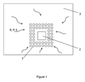
本発明の実施形態が図1に示されており、地震波シールドが、保護される建物の周りに位置決めされている。2列の円筒形の柱1があり、柱は正方形の格子の点に配置されている。柱は建物2から離間されており、そのため建物は柱の上に位置していない。湾曲した矢印は、建物に近づいてくる地震波を示しており、地震波はシールドによって止められる。地震波は、表面レーリー波R、バルク圧力波P、およびせん断波Sから作られている。この実施形態では、表土は土3である。柱は、柱の下部が岩盤に埋め込まれるため、岩盤に留め付けられている。
An embodiment of the invention is shown in FIG. 1, in which a seismic shield is positioned around a protected building. There are two rows of
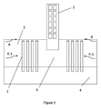
図2は、図1の実施形態と同様であるが、シールドを作る4列の柱1を有する、本発明の別の実施形態を示している。この図は、土3を通じて建物2に向かって進行するバルク圧力波P、せん断波S、およびレーリー(表面)波Rがシールドによってすべて止められることを示している。柱の下部は、岩盤4に埋め込まれているとして見られる。柱は、領域6をレーリー表面波R、バルク圧力波P、およびせん断波Sから保護する。
FIG. 2 is similar to the embodiment of FIG. 1, but shows another embodiment of the invention with four rows of
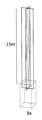
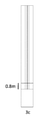
板5が取り付けられている柱1が図3に示されている。図は、柱および板を見えるようにするために表土が透明にされている、シールドの単位セルを示している。単位セルは1つの柱を含んでいる。柱は円筒形であり、30cmの直径を有している。岩盤の上での柱の高さは15mであり、岩盤に埋め込まれている柱の下部の高さは80cmであり、したがって柱の全体の高さは15.8mである。柱は、隣接する柱同士の間で延びる4つの板に取り付けられている。板5は10cmの厚さで1.7mの幅である(各々の板の半分だけが単位セルに示されている)。板は柱と同じ高さ(15.8m)である。シールドは、正方形の配列において互いの隣に図3の単位セルを多数配置することにより形成されている。板は、2つの隣接する柱の表面同士の間で延びている。
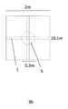
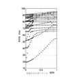
図3に示された柱から作られたシールドについての帯域図が図4に示されている。これは、20Hz未満の周波数についての阻止帯域を示している。これは、図3の単位セルの正方形の配列から作られたシールドが20Hz未満の周波数を伴う地震波を止めることを意味している。 A band diagram for the shield made from the pillars shown in Figure 3 is shown in Figure 4. This indicates a blocking band for frequencies below 20 Hz. This means that a shield made from the square array of unit cells in Figure 3 will stop seismic waves with frequencies below 20 Hz.
柱を形成する材料の例であるコンクリートのパラメータの典型的な値が[表1]に示されている。表土を形成する材料の例であるいくつかの種類の堆積土のパラメータの典型的な値が[表2]に示されている。 Typical values for concrete parameters, which are examples of materials that form columns, are shown in [Table 1]. Typical values for some types of sedimentary soil parameters that are examples of topsoil-forming materials are shown in [Table 2].


地震のシールドの一例では、1.2mの直径を各々有する多数の鋼鉄(7850kg/m3の密度)の円筒形の柱が、5mの深さである岩盤の上で、15mの深さである土の表土で使用される。各々の柱の下部が岩盤に埋め込まれ、下部は80cmの高さを有する。柱は、最も近くの隣接する柱の中心同士の間の距離が2mとなるように、正方形の配列で配置される。柱は、表土の表面に到達するように15.8mの高さである。約4.5Hzまでのゼロ周波数バンドギャップが、このようなシールドによってもたらされる。 In one example of a seismic shield, a large number of steel (7850 kg / m 3 densities) cylindrical columns, each with a diameter of 1.2 m, are 15 m deep on rock at a depth of 5 m and soil at a depth of 15 m. Used in the topsoil of. The lower part of each pillar is embedded in the bedrock, and the lower part has a height of 80 cm. The pillars are arranged in a square array so that the distance between the centers of the nearest adjacent pillars is 2 m. The pillars are 15.8m high to reach the surface of the topsoil. A zero frequency bandgap up to about 4.5Hz is provided by such a shield.
多数の柱は、10本の柱の3つの列で配置された30本の柱であり得る。 A large number of pillars can be 30 pillars arranged in 3 rows of 10 pillars.
地震のシールドの他の例では、0.2mの直径を各々有する多数の鋼鉄(7850kg/m3の密度)の円筒形の柱が、5mの深さである岩盤の上で、15mの深さである土の表土において使用される。柱は、最も近くの隣接する柱の中心同士の間の距離が2mとなるように、正方形の配列で配置される。さらに、柱は、厚さが0.2mの鋼鉄の板によって、最も近くの隣接する柱の各々に、各々結合される。したがって、柱と板とが一緒になって十字形の断面を有する。柱の下部80cmと板とが岩盤に埋め込まれる。柱は、表土の表面に到達するように15.8mの高さである。このシールドは、柱が岩盤に埋め込まれず、15mの高さとなるように、柱の下部を除去することにより変更されてもよい。このシールドは、柱が岩盤に埋め込まれず、15mの高さとなるように、柱の下部を除去することにより変更されてもよい。約26Hzまでのゼロ周波数バンドギャップが、このようなシールドによってもたらされる。この例のシールドは、0.3mの直径の柱を作ることにより変更されてもよい。 In another example of a seismic shield, a large number of steel (7850 kg / m 3 densities) cylindrical columns, each with a diameter of 0.2 m, are placed at a depth of 15 m on a bedrock that is 5 m deep. Used on the topsoil of some soil. The pillars are arranged in a square array so that the distance between the centers of the nearest adjacent pillars is 2 m. In addition, the columns are each joined to each of the nearest adjacent columns by a 0.2 m thick steel plate. Therefore, the pillars and plates together have a cruciform cross section. The lower 80 cm of the pillar and the board are embedded in the bedrock. The pillars are 15.8m high to reach the surface of the topsoil. This shield may be modified by removing the bottom of the pillar so that the pillar is not embedded in the bedrock and is 15 m high. This shield may be modified by removing the bottom of the pillar so that the pillar is not embedded in the bedrock and is 15 m high. A zero frequency bandgap up to about 26Hz is provided by such a shield. The shield in this example may be modified by making a pillar with a diameter of 0.3 m.
地震のシールドの他の例では、0.3mの直径を各々有する多数の鋼鉄(7850kg/m3の密度)の円筒形の柱が、5mの深さである岩盤の上で、15mの深さである土の表土において使用される。柱は、最も近くの隣接する柱の中心同士の間の距離が2mとなるように、ハチの巣状の配列で配置される。さらに、柱は、厚さが0.3mの鋼鉄の板によって、最も近くの隣接する柱の各々に、各々結合される。柱の下部80cmと板とが岩盤に埋め込まれる。柱は、表土の表面に到達するように15.8mの高さである。約20Hzまでのゼロ周波数バンドギャップが、このようなシールドによってもたらされる。 In another example of a seismic shield, a large number of steel (7850 kg / m 3 densities) cylindrical columns, each with a diameter of 0.3 m, are placed at a depth of 15 m on a bedrock that is 5 m deep. Used on the topsoil of some soil. The pillars are arranged in a honeycomb-like arrangement so that the distance between the centers of the nearest adjacent pillars is 2 m. In addition, the columns are each joined to each of the nearest adjacent columns by a 0.3 m thick steel plate. The lower 80 cm of the pillar and the board are embedded in the bedrock. The pillars are 15.8m high to reach the surface of the topsoil. A zero frequency bandgap up to about 20Hz is provided by such a shield.
六角形の格子を使用する同様の配列が、約18Hzまでのゼロ周波数バンドギャップを生成できる。 A similar array using a hexagonal grid can generate a zero frequency bandgap up to about 18Hz.
地震のシールドの他の例では、0.3mの直径を各々有する多数の鋼鉄(7850kg/m3の密度)の円筒形の柱が、5mの深さである岩盤の上で、15mの深さである土の表土において使用される。柱は、最も近くの隣接する柱の中心同士の間の距離が2mとなるように、正方形の配列で配置される。柱は、岩盤から7.5mの高さに位置付けられる0.2mの厚さの水平方向の鋼鉄の板を貫通している。このシールドは、3つまたは7つの等しく離間された水平方向の板を有するように変更され得る。柱は、表土の表面に到達するように15.8mの高さである。 In another example of a seismic shield, a large number of steel (7850 kg / m 3 densities) cylindrical columns, each with a diameter of 0.3 m, are placed at a depth of 15 m on a bedrock that is 5 m deep. Used on the topsoil of some soil. The pillars are arranged in a square array so that the distance between the centers of the nearest adjacent pillars is 2 m. The pillars penetrate a 0.2 m thick horizontal steel plate located 7.5 m above the bedrock. This shield can be modified to have 3 or 7 equally spaced horizontal plates. The pillars are 15.8m high to reach the surface of the topsoil.
地震のシールドのさらなる例では、0.6mの半径を各々有する多数の鋼鉄(7850kg/m3の密度)の円筒形の柱が、5mの深さである岩盤の上で、15mの深さである土の表土において使用される。各々の柱の下部が岩盤に埋め込まれ、下部は80cmの高さを有する。柱は、最も近くの隣接する柱の中心同士の間の距離が2mとなるように、正方形の配列で配置される。柱は、表土の表面に到達するように15.8mの高さである。このシールドは、柱が岩盤に埋め込まれず、15mの高さとなるように、柱の下部を除去することにより変更されてもよい。 In a further example of a seismic shield, a number of steel (7850 kg / m 3 densities) cylindrical columns, each with a radius of 0.6 m, are 15 m deep on rock, which is 5 m deep. Used on the topsoil of soil. The lower part of each pillar is embedded in the bedrock, and the lower part has a height of 80 cm. The pillars are arranged in a square array so that the distance between the centers of the nearest adjacent pillars is 2 m. The pillars are 15.8m high to reach the surface of the topsoil. This shield may be modified by removing the bottom of the pillar so that the pillar is not embedded in the bedrock and is 15 m high.
1 柱
2 建物
3 土
4 岩盤
6 領域
P バルク圧力波
R 表面レーリー波
S せん断波
1 pillar
2 Building
3 Sat
4 bedrock
6 areas
P bulk pressure wave
R surface Rayleigh wave
S shear wave
Claims (12)
Applications Claiming Priority (3)
| Application Number | Priority Date | Filing Date | Title |
|---|---|---|---|
| GBGB1617808.9A GB201617808D0 (en) | 2016-10-21 | 2016-10-21 | Seismic defence structures |
| GB1617808.9 | 2016-10-21 | ||
| PCT/EP2017/076844 WO2018073412A1 (en) | 2016-10-21 | 2017-10-20 | Seismic defence structures |
Publications (3)
| Publication Number | Publication Date |
|---|---|
| JP2020509259A JP2020509259A (en) | 2020-03-26 |
| JP2020509259A5 JP2020509259A5 (en) | 2020-11-26 |
| JP6993410B2 true JP6993410B2 (en) | 2022-01-13 |
Family
ID=57738276
Family Applications (1)
| Application Number | Title | Priority Date | Filing Date |
|---|---|---|---|
| JP2019521441A Active JP6993410B2 (en) | 2016-10-21 | 2017-10-20 | Seismic structure |
Country Status (6)
| Country | Link |
|---|---|
| US (1) | US11655610B2 (en) |
| EP (1) | EP3529420B1 (en) |
| JP (1) | JP6993410B2 (en) |
| CN (1) | CN110506144A (en) |
| GB (1) | GB201617808D0 (en) |
| WO (1) | WO2018073412A1 (en) |
Families Citing this family (9)
| Publication number | Priority date | Publication date | Assignee | Title |
|---|---|---|---|---|
| CN110398439B (en) * | 2019-08-20 | 2022-03-11 | 中国电建集团成都勘测设计研究院有限公司 | Soil density sand filling test method and sand filling device |
| CN112663684A (en) * | 2020-12-19 | 2021-04-16 | 北京工业大学 | Low-frequency damping nine-round-pile earthquake glume structure |
| CN112878384B (en) * | 2021-01-18 | 2022-07-26 | 西北工业大学 | Seismic metamaterial and method for blocking seismic lamb wave propagation |
| CN113389292A (en) * | 2021-06-17 | 2021-09-14 | 北京工业大学 | Wave barrier structure with low-frequency ultra-wide attenuation domain and manufacturing method |
| CN113389295A (en) * | 2021-06-17 | 2021-09-14 | 北京工业大学 | Combined steel type seismic surface wave barrier structure and manufacturing method thereof |
| CN113389294A (en) * | 2021-06-17 | 2021-09-14 | 北京工业大学 | Low-frequency damping cross fractal wave barrier structure and manufacturing method thereof |
| CN113389293A (en) * | 2021-06-17 | 2021-09-14 | 北京工业大学 | Inverse gradient cross steel type wave barrier structure and manufacturing method thereof |
| CN113818495B (en) * | 2021-09-16 | 2022-07-26 | 中南大学 | Periodic pile-wall structure aiming at low-frequency surface wave vibration isolation and construction method |
| CN114606988A (en) * | 2022-03-25 | 2022-06-10 | 广州地铁设计研究院股份有限公司 | Composite vibration damping device and preparation method |
Citations (4)
| Publication number | Priority date | Publication date | Assignee | Title |
|---|---|---|---|---|
| JP2000170194A (en) | 1998-12-08 | 2000-06-20 | Ohbayashi Corp | Base-isolation construction of structure |
| JP2005171702A (en) | 2003-12-15 | 2005-06-30 | Taisei Corp | Seismic response control structure of existing structure |
| JP2014214509A (en) | 2013-04-26 | 2014-11-17 | 大成建設株式会社 | Liquefaction countermeasure structure of foundation by structure load |
| JP2015165065A (en) | 2014-03-01 | 2015-09-17 | 大成建設株式会社 | liquefaction countermeasure structure |
Family Cites Families (16)
| Publication number | Priority date | Publication date | Assignee | Title |
|---|---|---|---|---|
| US1725136A (en) * | 1927-04-11 | 1929-08-20 | Winthrop Chem Co Inc | Basic phenolalkylether |
| US4484423A (en) * | 1981-10-26 | 1984-11-27 | Bechtel International Corporation | Seismic shield |
| SU1101536A1 (en) | 1982-06-08 | 1984-07-07 | Среднеазиатское Отделение Всесоюзного Государственного Научно-Исследовательского И Проектно-Конструкторского Института "Внипиэнергопром" | Earthquake-proof multistorey building or structure |
| US4683691A (en) * | 1986-02-24 | 1987-08-04 | Paul Malzahn | Protective annular construction and method of manufacture |
| DE3923427A1 (en) * | 1989-07-15 | 1991-01-24 | Clouth Gummiwerke Ag | BODY SOUND INSULATING MAT |
| JPH03103534A (en) | 1989-09-14 | 1991-04-30 | Kubota Corp | Countermeasure structure for liquefaction of building |
| FR2660353A1 (en) * | 1990-03-30 | 1991-10-04 | Technologies Speciales Ingenie | Earthquake resistance methods and shields |
| JPH04155018A (en) | 1990-10-19 | 1992-05-28 | Kubota Corp | Construction of foundation for building |
| JP4222812B2 (en) * | 2002-11-05 | 2009-02-12 | 宏和 竹宮 | Anti-vibration method |
| FI117603B (en) * | 2004-11-26 | 2006-12-15 | Tieliikelaitos | Procedure for protecting an object from vibration caused by traffic |
| JP2008223302A (en) * | 2007-03-12 | 2008-09-25 | Nishimatsu Constr Co Ltd | Lateral flow restraining apparatus for liquefaction layer |
| JP2014051852A (en) * | 2012-09-10 | 2014-03-20 | Takenaka Komuten Co Ltd | Ground improvement structure |
| FR3001744B1 (en) * | 2013-02-04 | 2015-02-13 | Snf Sas | METHOD FOR PROTECTING A BUILDING OF SEISMIC WAVES BY USING SUPERABSORBENT POLYMERS |
| CN103452145A (en) * | 2013-05-17 | 2013-12-18 | 林建省 | Lime soil pile and determination of ultimate tip resistance of pile endpoint soil and ultimate side resistance of pile periphery soil |
| CN104570065B (en) * | 2013-10-09 | 2017-05-03 | 中国石油化工股份有限公司 | Method for quantitatively inverting porosity by using seismic wave impedance |
| GB2537317B (en) * | 2014-04-07 | 2020-02-12 | Halliburton Energy Services Inc | Soil and rock grouting using a hydrajetting tool |
-
2016
- 2016-10-21 GB GBGB1617808.9A patent/GB201617808D0/en not_active Ceased
-
2017
- 2017-10-20 WO PCT/EP2017/076844 patent/WO2018073412A1/en unknown
- 2017-10-20 CN CN201780076290.XA patent/CN110506144A/en active Pending
- 2017-10-20 JP JP2019521441A patent/JP6993410B2/en active Active
- 2017-10-20 EP EP17787180.3A patent/EP3529420B1/en active Active
- 2017-10-20 US US16/343,605 patent/US11655610B2/en active Active
Patent Citations (4)
| Publication number | Priority date | Publication date | Assignee | Title |
|---|---|---|---|---|
| JP2000170194A (en) | 1998-12-08 | 2000-06-20 | Ohbayashi Corp | Base-isolation construction of structure |
| JP2005171702A (en) | 2003-12-15 | 2005-06-30 | Taisei Corp | Seismic response control structure of existing structure |
| JP2014214509A (en) | 2013-04-26 | 2014-11-17 | 大成建設株式会社 | Liquefaction countermeasure structure of foundation by structure load |
| JP2015165065A (en) | 2014-03-01 | 2015-09-17 | 大成建設株式会社 | liquefaction countermeasure structure |
Also Published As
| Publication number | Publication date |
|---|---|
| CN110506144A (en) | 2019-11-26 |
| US11655610B2 (en) | 2023-05-23 |
| GB201617808D0 (en) | 2016-12-07 |
| EP3529420A1 (en) | 2019-08-28 |
| EP3529420B1 (en) | 2023-11-22 |
| JP2020509259A (en) | 2020-03-26 |
| US20200048858A1 (en) | 2020-02-13 |
| WO2018073412A1 (en) | 2018-04-26 |
Similar Documents
| Publication | Publication Date | Title |
|---|---|---|
| JP6993410B2 (en) | Seismic structure | |
| US20140305049A1 (en) | Earthquaske-proof barrier using buried resonant cylinders | |
| CN112663682A (en) | Square earthquake metasoma structure with cross-shaped cavity | |
| CN113684866A (en) | Low-frequency wide-band-gap seismic glume-plate structure containing depleted uranium | |
| Lei et al. | Locally resonant periodic wave barriers for vibration isolation in subway engineering | |
| CN113389292A (en) | Wave barrier structure with low-frequency ultra-wide attenuation domain and manufacturing method | |
| CN111519668A (en) | Sandwich multilayer assembled vibration isolation trench | |
| CN113389295A (en) | Combined steel type seismic surface wave barrier structure and manufacturing method thereof | |
| JP2004156259A (en) | Vibration-isolating method | |
| CN113389293A (en) | Inverse gradient cross steel type wave barrier structure and manufacturing method thereof | |
| CN112554169A (en) | Square pile seismic surface wave metasurface structure | |
| CN104674853B (en) | A kind of vibration isolation ditch | |
| CN112554242B (en) | Low-frequency band-gap five-hole seismic metamaterial structure | |
| US5174082A (en) | Anti-seismic shields | |
| RU2475595C1 (en) | Barrier to protect developed areas against surface seismic waves | |
| Kavand et al. | Field Testing on active isolation of vibrating foundations in Middle-frequency range | |
| CN209837120U (en) | Arc-shaped and variable-depth shock insulation ditch | |
| CN110761132A (en) | Assembled vibration isolation barrier | |
| RU2298614C1 (en) | Method for building or building structure protection against vibration | |
| CN112663684A (en) | Low-frequency damping nine-round-pile earthquake glume structure | |
| CN112663685A (en) | Low-frequency damping earthquake glume plate structure | |
| RU2713837C1 (en) | Device for protection of buildings or structures against buried explosions | |
| Takemiya et al. | Environmental vibration control by active piezo-actuator system | |
| WO2024023838A1 (en) | Seismobrick unit cell for protection of buildings and equipment against low-frequency seismic surface disturbances | |
| JP5216655B2 (en) | Improved ground |
Legal Events
| Date | Code | Title | Description |
|---|---|---|---|
| A521 | Request for written amendment filed |
Free format text: JAPANESE INTERMEDIATE CODE: A523 Effective date: 20191112 |
|
| A521 | Request for written amendment filed |
Free format text: JAPANESE INTERMEDIATE CODE: A523 Effective date: 20201016 |
|
| A621 | Written request for application examination |
Free format text: JAPANESE INTERMEDIATE CODE: A621 Effective date: 20201016 |
|
| A977 | Report on retrieval |
Free format text: JAPANESE INTERMEDIATE CODE: A971007 Effective date: 20211027 |
|
| TRDD | Decision of grant or rejection written | ||
| A01 | Written decision to grant a patent or to grant a registration (utility model) |
Free format text: JAPANESE INTERMEDIATE CODE: A01 Effective date: 20211115 |
|
| A61 | First payment of annual fees (during grant procedure) |
Free format text: JAPANESE INTERMEDIATE CODE: A61 Effective date: 20211209 |
|
| R150 | Certificate of patent or registration of utility model |
Ref document number: 6993410 Country of ref document: JP Free format text: JAPANESE INTERMEDIATE CODE: R150 |