JP6991899B2 - Printing equipment, control methods and programs - Google Patents
Printing equipment, control methods and programs Download PDFInfo
- Publication number
- JP6991899B2 JP6991899B2 JP2018046012A JP2018046012A JP6991899B2 JP 6991899 B2 JP6991899 B2 JP 6991899B2 JP 2018046012 A JP2018046012 A JP 2018046012A JP 2018046012 A JP2018046012 A JP 2018046012A JP 6991899 B2 JP6991899 B2 JP 6991899B2
- Authority
- JP
- Japan
- Prior art keywords
- opening
- closing portion
- printing
- closing
- executed
- Prior art date
- Legal status (The legal status is an assumption and is not a legal conclusion. Google has not performed a legal analysis and makes no representation as to the accuracy of the status listed.)
- Active
Links
Images


Classifications
-
- G—PHYSICS
- G06—COMPUTING OR CALCULATING; COUNTING
- G06K—GRAPHICAL DATA READING; PRESENTATION OF DATA; RECORD CARRIERS; HANDLING RECORD CARRIERS
- G06K15/00—Arrangements for producing a permanent visual presentation of the output data, e.g. computer output printers
- G06K15/002—Interacting with the operator
- G06K15/005—Interacting with the operator only locally
-
- G—PHYSICS
- G06—COMPUTING OR CALCULATING; COUNTING
- G06F—ELECTRIC DIGITAL DATA PROCESSING
- G06F3/00—Input arrangements for transferring data to be processed into a form capable of being handled by the computer; Output arrangements for transferring data from processing unit to output unit, e.g. interface arrangements
- G06F3/12—Digital output to print unit, e.g. line printer, chain printer
- G06F3/1201—Dedicated interfaces to print systems
- G06F3/1202—Dedicated interfaces to print systems specifically adapted to achieve a particular effect
- G06F3/1218—Reducing or saving of used resources, e.g. avoiding waste of consumables or improving usage of hardware resources
- G06F3/122—Reducing or saving of used resources, e.g. avoiding waste of consumables or improving usage of hardware resources with regard to computing resources, e.g. memory, CPU
-
- B—PERFORMING OPERATIONS; TRANSPORTING
- B41—PRINTING; LINING MACHINES; TYPEWRITERS; STAMPS
- B41J—TYPEWRITERS; SELECTIVE PRINTING MECHANISMS, i.e. MECHANISMS PRINTING OTHERWISE THAN FROM A FORME; CORRECTION OF TYPOGRAPHICAL ERRORS
- B41J2/00—Typewriters or selective printing mechanisms characterised by the printing or marking process for which they are designed
- B41J2/005—Typewriters or selective printing mechanisms characterised by the printing or marking process for which they are designed characterised by bringing liquid or particles selectively into contact with a printing material
- B41J2/01—Ink jet
- B41J2/135—Nozzles
- B41J2/145—Arrangement thereof
-
- B—PERFORMING OPERATIONS; TRANSPORTING
- B41—PRINTING; LINING MACHINES; TYPEWRITERS; STAMPS
- B41J—TYPEWRITERS; SELECTIVE PRINTING MECHANISMS, i.e. MECHANISMS PRINTING OTHERWISE THAN FROM A FORME; CORRECTION OF TYPOGRAPHICAL ERRORS
- B41J2/00—Typewriters or selective printing mechanisms characterised by the printing or marking process for which they are designed
- B41J2/005—Typewriters or selective printing mechanisms characterised by the printing or marking process for which they are designed characterised by bringing liquid or particles selectively into contact with a printing material
- B41J2/01—Ink jet
- B41J2/17—Ink jet characterised by ink handling
- B41J2/175—Ink supply systems ; Circuit parts therefor
-
- B—PERFORMING OPERATIONS; TRANSPORTING
- B41—PRINTING; LINING MACHINES; TYPEWRITERS; STAMPS
- B41J—TYPEWRITERS; SELECTIVE PRINTING MECHANISMS, i.e. MECHANISMS PRINTING OTHERWISE THAN FROM A FORME; CORRECTION OF TYPOGRAPHICAL ERRORS
- B41J29/00—Details of, or accessories for, typewriters or selective printing mechanisms not otherwise provided for
- B41J29/38—Drives, motors, controls or automatic cut-off devices for the entire printing mechanism
- B41J29/393—Devices for controlling or analysing the entire machine ; Controlling or analysing mechanical parameters involving printing of test patterns
-
- B—PERFORMING OPERATIONS; TRANSPORTING
- B41—PRINTING; LINING MACHINES; TYPEWRITERS; STAMPS
- B41J—TYPEWRITERS; SELECTIVE PRINTING MECHANISMS, i.e. MECHANISMS PRINTING OTHERWISE THAN FROM A FORME; CORRECTION OF TYPOGRAPHICAL ERRORS
- B41J29/00—Details of, or accessories for, typewriters or selective printing mechanisms not otherwise provided for
- B41J29/46—Applications of alarms, e.g. responsive to approach of end of line
-
- G—PHYSICS
- G06—COMPUTING OR CALCULATING; COUNTING
- G06F—ELECTRIC DIGITAL DATA PROCESSING
- G06F3/00—Input arrangements for transferring data to be processed into a form capable of being handled by the computer; Output arrangements for transferring data from processing unit to output unit, e.g. interface arrangements
- G06F3/12—Digital output to print unit, e.g. line printer, chain printer
- G06F3/1201—Dedicated interfaces to print systems
- G06F3/1202—Dedicated interfaces to print systems specifically adapted to achieve a particular effect
- G06F3/1203—Improving or facilitating administration, e.g. print management
- G06F3/1204—Improving or facilitating administration, e.g. print management resulting in reduced user or operator actions, e.g. presetting, automatic actions, using hardware token storing data
-
- G—PHYSICS
- G06—COMPUTING OR CALCULATING; COUNTING
- G06F—ELECTRIC DIGITAL DATA PROCESSING
- G06F3/00—Input arrangements for transferring data to be processed into a form capable of being handled by the computer; Output arrangements for transferring data from processing unit to output unit, e.g. interface arrangements
- G06F3/12—Digital output to print unit, e.g. line printer, chain printer
- G06F3/1201—Dedicated interfaces to print systems
- G06F3/1202—Dedicated interfaces to print systems specifically adapted to achieve a particular effect
- G06F3/1218—Reducing or saving of used resources, e.g. avoiding waste of consumables or improving usage of hardware resources
- G06F3/1219—Reducing or saving of used resources, e.g. avoiding waste of consumables or improving usage of hardware resources with regard to consumables, e.g. ink, toner, paper
-
- G—PHYSICS
- G06—COMPUTING OR CALCULATING; COUNTING
- G06F—ELECTRIC DIGITAL DATA PROCESSING
- G06F3/00—Input arrangements for transferring data to be processed into a form capable of being handled by the computer; Output arrangements for transferring data from processing unit to output unit, e.g. interface arrangements
- G06F3/12—Digital output to print unit, e.g. line printer, chain printer
- G06F3/1201—Dedicated interfaces to print systems
- G06F3/1223—Dedicated interfaces to print systems specifically adapted to use a particular technique
- G06F3/1229—Printer resources management or printer maintenance, e.g. device status, power levels
- G06F3/1231—Device related settings, e.g. IP address, Name, Identification
-
- G—PHYSICS
- G06—COMPUTING OR CALCULATING; COUNTING
- G06F—ELECTRIC DIGITAL DATA PROCESSING
- G06F3/00—Input arrangements for transferring data to be processed into a form capable of being handled by the computer; Output arrangements for transferring data from processing unit to output unit, e.g. interface arrangements
- G06F3/12—Digital output to print unit, e.g. line printer, chain printer
- G06F3/1201—Dedicated interfaces to print systems
- G06F3/1278—Dedicated interfaces to print systems specifically adapted to adopt a particular infrastructure
- G06F3/1284—Local printer device
-
- G—PHYSICS
- G06—COMPUTING OR CALCULATING; COUNTING
- G06K—GRAPHICAL DATA READING; PRESENTATION OF DATA; RECORD CARRIERS; HANDLING RECORD CARRIERS
- G06K15/00—Arrangements for producing a permanent visual presentation of the output data, e.g. computer output printers
- G06K15/02—Arrangements for producing a permanent visual presentation of the output data, e.g. computer output printers using printers
- G06K15/10—Arrangements for producing a permanent visual presentation of the output data, e.g. computer output printers using printers by matrix printers
- G06K15/102—Arrangements for producing a permanent visual presentation of the output data, e.g. computer output printers using printers by matrix printers using ink jet print heads
Landscapes
- Engineering & Computer Science (AREA)
- Theoretical Computer Science (AREA)
- Physics & Mathematics (AREA)
- General Engineering & Computer Science (AREA)
- General Physics & Mathematics (AREA)
- Human Computer Interaction (AREA)
- Mathematical Physics (AREA)
- Accessory Devices And Overall Control Thereof (AREA)
- Ink Jet (AREA)
- Facsimiles In General (AREA)
Description
本発明は印刷装置、制御方法及びプログラムに関するものである。 The present invention relates to printing devices, control methods and programs.
印刷部を覆う筐体の一部であり、開閉可能なドア等の開閉部を有し、当該開閉部をロック及びロック解除可能な印刷装置が知られている。特許文献1には、画像形成動作が行われているときに、開閉部をロックし、画像形成動作が終了すると、開閉部のロックを解除する装置が記載されている。 A printing device that is a part of a housing that covers a printing portion, has an opening / closing portion such as a door that can be opened / closed, and can lock / unlock the opening / closing portion is known. Patent Document 1 describes a device that locks the opening / closing portion when the image forming operation is being performed and unlocks the opening / closing portion when the image forming operation is completed.
ところで例えば、開閉部がロックされていることを知らないユーザは、開閉部がロックされている状態において、開閉部に対して開閉部を開放するための操作を実行してしまうことがある。開閉部がロックされているにもかかわらず、開閉部に対して開閉部を開放するためのユーザ操作が継続して実行されてしまうと、例えば、開閉部のロック機構が破損してしまう等の課題が生じる。 By the way, for example, a user who does not know that the opening / closing portion is locked may execute an operation for opening the opening / closing portion with respect to the opening / closing portion in a state where the opening / closing portion is locked. If the user operation for opening the opening / closing part is continuously executed for the opening / closing part even though the opening / closing part is locked, for example, the locking mechanism of the opening / closing part may be damaged. Challenges arise.
特許文献1に記載の装置は、開閉部がロックされている状態において、開閉部に対して開閉部を開放するためのユーザ操作が実行されてしまった場合の制御について考慮されていない。そのため、特許文献1には、開閉部がロックされているにもかかわらず、開閉部に対して開閉部を開放するための操作が継続して実行されてしまうことがあるという課題がある。 The device described in Patent Document 1 does not consider the control when the user operation for opening the opening / closing portion is executed with respect to the opening / closing portion in the state where the opening / closing portion is locked. Therefore, Patent Document 1 has a problem that an operation for opening the opening / closing portion with respect to the opening / closing portion may be continuously executed even though the opening / closing portion is locked.
本発明は、上述の課題を鑑みてなされたものであり、開閉部がロックされているにもかかわらず、開閉部に対して開閉部を開放するためのユーザ操作が継続して実行されてしまうことを抑制することを目的とする。 The present invention has been made in view of the above-mentioned problems, and even though the opening / closing portion is locked, the user operation for opening the opening / closing portion with respect to the opening / closing portion is continuously executed. The purpose is to suppress this.
上記課題を解決するため、本発明の印刷装置は、印刷装置であって、
印刷部によって印刷を実行する印刷手段と、
前記印刷部を覆う筐体の一部である開閉可能な開閉部をロックするロック手段と、
前記開閉部がロックされている状態で、前記開閉部に対する、前記開閉部を開放するためのユーザ操作が実行された場合、所定の通知処理を実行する通知手段と、
前記開閉部に対する、前記開閉部を開放するためのユーザ操作が実行された場合、前記所定の通知処理を実行するか否かを設定する第1設定手段を有し、
前記開閉部がロックされている状態では、前記開閉部に対する前記開閉部を開けるためのユーザ操作が行われても、前記開閉部が開放されないことを特徴とする。
また、印刷装置であって、
印刷部によって印刷を実行する印刷手段と、
前記印刷部を覆う筐体の一部である開閉可能な開閉部をロックするロック手段と、
前記開閉部がロックされている状態で、前記開閉部に対する、前記開閉部を開放するためのユーザ操作が実行された場合、所定の通知処理を実行する通知手段と、
前記開閉部がロックされており、且つ前記印刷装置が、第1の状態よりも消費電力が低い第2の状態である状態において、前記開閉部に対する、前記開閉部を開放するためのユーザ操作が実行された場合、前記印刷装置を前記第2の状態から前記第1の状態に遷移させる遷移手段を有し、
前記開閉部がロックされている状態では、前記開閉部に対する前記開閉部を開けるためのユーザ操作が行われても、前記開閉部が開放されず、
前記開閉部がロックされており、且つ前記印刷装置が前記第2の状態である状態において、前記開閉部に対する、前記開閉部を開放するためのユーザ操作が実行された場合、前記印刷装置が前記第2の状態から前記第1の状態に遷移した後、前記通知処理が実行されることを特徴とする。
また、印刷装置であって、
印刷部によって印刷を実行する印刷手段と、
前記印刷部を覆う筐体の一部である開閉可能な開閉部をロックするロック手段と、
前記開閉部がロックされている状態で、前記開閉部に対する、前記開閉部を開放するためのユーザ操作が実行された場合、所定の通知処理を実行する通知手段と、を有し、
前記開閉部がロックされている状態では、前記開閉部に対する前記開閉部を開けるためのユーザ操作が行われても、前記開閉部が開放されず、
前記開閉部がロックされており、且つ前記印刷装置が、第1の状態よりも消費電力が低い第2の状態である状態において、前記開閉部に対する、前記開閉部を開放するためのユーザ操作が実行された場合、前記所定の通知処理として、第1の通知処理が実行され、前記開閉部がロックされており、且つ前記印刷装置が前記第1の状態である状態において、前記開閉部に対する、前記開閉部を開放するためのユーザ操作が実行された場合、前記所定の通知処理として、前記第1の通知処理と異なる第2の通知処理が実行されることを特徴とする。
また、印刷装置であって、
印刷部によって印刷を実行する印刷手段と、
前記印刷部を覆う筐体の一部である開閉可能な開閉部をロックするロック手段と、
前記開閉部がロックされている状態で、前記開閉部に対する、前記開閉部を開放するためのユーザ操作が実行された場合、所定の通知処理を実行する通知手段と、を有し、
前記開閉部がロックされている状態では、前記開閉部に対する前記開閉部を開けるためのユーザ操作が行われても、前記開閉部が開放されず、
前記開閉部がロックされており、且つ前記印刷装置が印刷を実行中である状態において、前記開閉部に対する、前記開閉部を開放するためのユーザ操作が実行された場合、前記所定の通知処理として、第1の通知処理が実行され、前記開閉部がロックされており、且つ前記印刷装置が印刷を実行中でない状態において、前記開閉部に対する、前記開閉部を開放するためのユーザ操作が実行された場合、前記所定の通知処理として、前記第1の通知処理と異なる第2の通知処理が実行されることを特徴とする。
また、印刷装置であって、
印刷部によって印刷を実行する印刷手段と、
前記印刷部を覆う筐体の一部である開閉可能な開閉部をロックするロック手段と、
前記開閉部がロックされている状態で、前記開閉部に対する、前記開閉部を開放するためのユーザ操作が実行された場合、所定の通知処理を実行する通知手段と、を有し、
前記開閉部がロックされている状態では、前記開閉部に対する前記開閉部を開けるためのユーザ操作が行われても、前記開閉部が開放されず、
前記開閉部がロックされている状態で、前記開閉部に対する、前記開閉部を開放するためのユーザ操作が、所定の時間以上連続して実行された場合、第1の通知処理が実行され、前記開閉部がロックされている状態で、前記開閉部に対する、前記開閉部を開放するためのユーザ操作が、所定の時間未満連続して実行された場合、前記第1の通知処理と異なる第2の通知処理が実行されることを特徴とする。
In order to solve the above problems, the printing apparatus of the present invention is a printing apparatus.
A printing means that executes printing by the printing unit,
A locking means for locking an openable / closable opening / closing portion that is a part of a housing covering the printing portion.
When a user operation for opening the opening / closing portion is executed for the opening / closing portion while the opening / closing portion is locked, a notification means for executing a predetermined notification process and a notification means.
It has a first setting means for setting whether or not to execute the predetermined notification process when a user operation for opening the opening / closing unit is executed for the opening / closing unit .
When the opening / closing portion is locked, the opening / closing portion is not opened even if a user operation for opening the opening / closing portion is performed on the opening / closing portion.
It is also a printing device.
A printing means that executes printing by the printing unit,
A locking means for locking an openable / closable opening / closing portion that is a part of a housing covering the printing portion.
When a user operation for opening the opening / closing portion is executed for the opening / closing portion while the opening / closing portion is locked, a notification means for executing a predetermined notification process and a notification means.
In a state where the opening / closing portion is locked and the printing device is in the second state in which the power consumption is lower than that in the first state, a user operation for opening the opening / closing portion is performed on the opening / closing portion. When executed, it has a transition means for transitioning the printing apparatus from the second state to the first state.
In the state where the opening / closing portion is locked, even if a user operation for opening the opening / closing portion is performed on the opening / closing portion, the opening / closing portion is not opened.
When the opening / closing section is locked and the printing device is in the second state, when a user operation for opening the opening / closing section is executed for the opening / closing section, the printing device is said to be said. After transitioning from the second state to the first state, the notification process is executed.
It is also a printing device.
A printing means that executes printing by the printing unit,
A locking means for locking an openable / closable opening / closing portion that is a part of a housing covering the printing portion.
It has a notification means for executing a predetermined notification process when a user operation for opening the opening / closing portion is executed for the opening / closing portion in a state where the opening / closing portion is locked.
In the state where the opening / closing portion is locked, even if a user operation for opening the opening / closing portion is performed on the opening / closing portion, the opening / closing portion is not opened.
In a state where the opening / closing portion is locked and the printing device is in the second state in which the power consumption is lower than that in the first state, a user operation for opening the opening / closing portion is performed on the opening / closing portion. When executed, the first notification process is executed as the predetermined notification process, the opening / closing section is locked, and the printing device is in the first state, the opening / closing section is subjected to the first notification process. When a user operation for opening the opening / closing unit is executed, a second notification process different from the first notification process is executed as the predetermined notification process.
It is also a printing device.
A printing means that executes printing by the printing unit,
A locking means for locking an openable / closable opening / closing portion that is a part of a housing covering the printing portion.
It has a notification means for executing a predetermined notification process when a user operation for opening the opening / closing portion is executed for the opening / closing portion in a state where the opening / closing portion is locked.
In the state where the opening / closing portion is locked, even if a user operation for opening the opening / closing portion is performed on the opening / closing portion, the opening / closing portion is not opened.
When the user operation for opening the opening / closing unit is executed for the opening / closing unit while the opening / closing unit is locked and the printing device is executing printing, the predetermined notification process is performed. , The first notification process is executed, the opening / closing part is locked, and the user operation for opening the opening / closing part is executed for the opening / closing part in a state where the printing device is not executing printing. If this is the case, the predetermined notification process is characterized in that a second notification process different from the first notification process is executed.
It is also a printing device.
A printing means that executes printing by the printing unit,
A locking means for locking an openable / closable opening / closing portion that is a part of a housing covering the printing portion.
It has a notification means for executing a predetermined notification process when a user operation for opening the opening / closing portion is executed for the opening / closing portion in a state where the opening / closing portion is locked.
In the state where the opening / closing portion is locked, even if a user operation for opening the opening / closing portion is performed on the opening / closing portion, the opening / closing portion is not opened.
When the user operation for opening the opening / closing portion for the opening / closing portion is continuously executed for a predetermined time or longer while the opening / closing portion is locked, the first notification process is executed. When the user operation for opening the opening / closing portion for the opening / closing portion is continuously executed for less than a predetermined time while the opening / closing portion is locked, a second notification process different from the first notification process is performed. The feature is that the notification process is executed.
本発明により、開閉部がロックされているにもかかわらず、開閉部に対して開閉部を開放するためのユーザ操作が継続して実行されてしまうことを抑制することができる。 According to the present invention, it is possible to prevent the user operation for opening the opening / closing portion from being continuously executed with respect to the opening / closing portion even though the opening / closing portion is locked.
(第1実施形態)
本実施形態の印刷装置について説明する。印刷装置として、本実施形態では、インクジェット方式による印刷を行う装置を例示しているが、これに限定されない。本発明は、インクジェット方式以外の印刷方式(電子写真方式、熱昇華方式等)による印刷を行う装置にも適用可能である。
(First Embodiment)
The printing apparatus of this embodiment will be described. As the printing device, the present embodiment exemplifies a device that performs printing by an inkjet method, but the present invention is not limited to this. The present invention can also be applied to an apparatus that prints by a printing method (electrophotograph method, thermal sublimation method, etc.) other than the inkjet method.
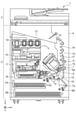
図1は、本実施形態で使用するインクジェット印刷装置1(以下、印刷装置1)の内部構成図である。インクジェット印刷装置とは、記録剤としてインクを吐出することによって、紙等の記録媒体上に画像を形成する装置である。図において、x方向は水平方向、y方向(垂直方向)は後述する印刷ヘッド8において吐出口が配列する方向、z方向は鉛直方向をそれぞれ示す。
FIG. 1 is an internal configuration diagram of an inkjet printing device 1 (hereinafter referred to as a printing device 1) used in the present embodiment. An inkjet printing device is a device that forms an image on a recording medium such as paper by ejecting ink as a recording agent. In the figure, the x direction indicates the horizontal direction, the y direction (vertical direction) indicates the direction in which the ejection ports are arranged in the
印刷装置1は、プリント部(印刷部)2とスキャナ部3を備える複合機であり、印刷動作と読取動作に関する様々な処理を、プリント部2とスキャナ部3で個別にあるいは連動して実行することができる。スキャナ部3は、ADF(オートドキュメントフィーダ)とFBS(フラットベッドスキャナ)を備えており、ADFで自動給紙される原稿の読み取りと、ユーザによってFBSの原稿台に置かれた原稿の読み取り(スキャン)を行うことができる。なお、本実施形態はプリント部2とスキャナ部3を併せ持った複合機であるが、スキャナ部3を備えない形態であってもよい。図1は、印刷装置1が印刷動作も読取動作も行っていない待機状態にあるときを示す。
The printing device 1 is a multifunction device including a printing unit (printing unit) 2 and a
プリント部2において、筐体4の鉛直方向下方の底部には、記録媒体(カットシート)Sを収容するための第1カセット5Aと第2カセット5Bが着脱可能に設置されている。第1カセット5AにはA4サイズまでの比較的小さな記録媒体が、第2カセット5BにはA3サイズまでの比較的大きな記録媒体が、平積みに収容されている。第1カセット5A近傍には、収容されている記録媒体を1枚ずつ分離して給送するための第1給送ユニット6Aが設けられている。同様に、第2カセット5B近傍には、第2給送ユニット6Bが設けられている。印刷動作が行われる際にはいずれか一方のカセットから選択的に記録媒体Sが給送される。
In the
搬送ローラ7、排出ローラ12、ピンチローラ7a、拍車7b、ガイド18、インナーガイド19およびフラッパ11は、記録媒体Sを所定の方向に導くための搬送機構である。搬送ローラ7は、印刷ヘッド8の上流側に配され、不図示の搬送モータによって駆動される駆動ローラである。ピンチローラ7aは、搬送ローラ7と共に記録媒体Sをニップして回転する従動ローラである。排出ローラ12は、印刷ヘッド8の下流側に配され、不図示の搬送モータによって駆動される駆動ローラである。拍車7bは、排出ローラ12と共に記録媒体Sを挟持して搬送する。
The
ガイド18は、記録媒体Sの搬送経路に設けられ、記録媒体Sを所定の方向に案内する。インナーガイド19は、y方向に延在する部材で湾曲した側面を有し、当該側面に沿って記録媒体Sを案内する。フラッパ11は、両面印刷動作の際に、記録媒体Sが搬送される方向を切り替えるための部材である。排出トレイ13は、印刷動作が完了し排出ローラ12によって排出された記録媒体Sを積載保持するためのトレイである。
The
本実施形態の印刷ヘッド8は、フルラインタイプのカラーインクジェット印刷ヘッドであり、印刷データに従ってインクを吐出する吐出口が、図1におけるy方向に沿って記録媒体Sの幅に相当する分だけ複数配列されている。印刷ヘッド8が待機位置にあるとき、印刷ヘッド8の吐出口面8aは、図1のようにキャップユニット10によってキャップされている。印刷動作を行う際は、後述するプリントコントローラ202によって、吐出口面8aがプラテン9と対向するように印刷ヘッド8の向きが変更される。プラテン9は、y方向に延在する平板によって構成され、印刷ヘッド8によって印刷動作が行われる記録媒体Sを背面から支持する。印刷ヘッド8の待機位置から印刷位置への移動については、後に詳しく説明する。
The
インクタンクユニット(保持部)14は、印刷ヘッド8へ供給される4色のインクをそれぞれ貯留する。インク供給ユニット15は、インクタンクユニット14と印刷ヘッド8を接続する流路の途中に設けられ、印刷ヘッド8内のインクの圧力及び流量を適切な範囲に調整する。本実施形態では循環型のインク供給系を採用しており、インク供給ユニット15は印刷ヘッド8へ供給されるインクの圧力と印刷ヘッド8から回収されるインクの流量を適切な範囲に調整する。
The ink tank unit (holding unit) 14 stores inks of four colors supplied to the
メンテナンスユニット16は、キャップユニット10とワイピングユニット17を備え、所定のタイミングにこれらを作動させて、印刷ヘッド8に対するメンテナンス動作を行う。メンテナンス動作については後に詳しく説明する。
The
メンテナンスユニット16にはユーザ交換可能なMTC(回収部)20が供えられている。MTC20は、インクタンクが保持していたインクのうち、印刷に用いられない廃インクを回収し、保持する。
The
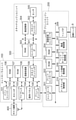
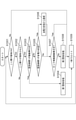
図2は、印刷装置1における制御構成を示すブロック図である。制御構成は、主にプリント部2を統括するプリントエンジンユニット200と、スキャナ部3を統括するスキャナエンジンユニット300と、印刷装置1全体を統括するコントローラユニット100によって構成されている。プリントコントローラ202は、コントローラユニット100のメインコントローラ101の指示に従ってプリントエンジンユニット200の各種機構を制御する。スキャナエンジンユニット300の各種機構は、コントローラユニット100のメインコントローラ101によって制御される。以下に制御構成の詳細について説明する。
FIG. 2 is a block diagram showing a control configuration in the printing apparatus 1. The control configuration is mainly composed of a
コントローラユニット100において、CPUにより構成されるメインコントローラ101は、ROM107に記憶されているプログラムや各種パラメータに従って、RAM106をワークエリアとしながら印刷装置1全体を制御する。例えば、ホストI/F102またはワイヤレスI/F103を介してホスト装置400から印刷ジョブが入力されると、メインコントローラ101の指示に従って、画像処理部108が受信した画像データに対して所定の画像処理を施す。そして、メインコントローラ101はプリントエンジンI/F105を介して、画像処理を施した画像データをプリントエンジンユニット200へ送信する。
In the
なお、印刷装置1は無線通信や有線通信を介してホスト装置400から画像データを取得しても良いし、印刷装置1に接続された外部記憶装置(USBメモリ等)から画像データを取得しても良い。無線通信や有線通信に利用される通信方式は限定されない。例えば、無線通信に利用される通信方式として、Wi-Fi(Wireless Fidelity)(登録商標)やBluetooth(登録商標)が適用可能である。また、有線通信に利用される通信方式としては、USB(Universal Serial Bus)等が適用可能である。また、例えばホスト装置400から読取コマンドが入力されると、メインコントローラ101は、スキャナエンジンI/F109を介してこのコマンドをスキャナ部3に送信する。
The printing device 1 may acquire image data from the
操作パネル(表示部)104は、ユーザが印刷装置1に対して入出力を行うための機構である。ユーザは、操作パネル104を介してコピーやスキャン等の動作を指示したり、印刷モードを設定したり、印刷装置1の情報を認識したりすることができる。
The operation panel (display unit) 104 is a mechanism for the user to input / output to / from the printing device 1. The user can instruct operations such as copying and scanning via the
プリントエンジンユニット200において、CPUにより構成されるプリントコントローラ202は、ROM203に記憶されているプログラムや各種パラメータに従って、RAM204をワークエリアとしながら、プリント部2が備える各種機構を制御する。コントローラI/F201を介して各種コマンドや画像データが受信されると、プリントコントローラ202は、これを一旦RAM204に保存する。印刷ヘッド8が印刷動作に利用できるように、プリントコントローラ202は画像処理コントローラ205に、保存した画像データを印刷データへ変換させる。印刷データが生成されると、プリントコントローラ202は、ヘッドI/F206を介して印刷ヘッド8に印刷データに基づく印刷動作を実行させる。この際、プリントコントローラ202は、搬送制御部207を介して図1に示す給送ユニット6A、6B、搬送ローラ7、排出ローラ12、フラッパ11を駆動して、記録媒体Sを搬送する。プリントコントローラ202の指示に従って、記録媒体Sの搬送動作に連動して印刷ヘッド8による印刷動作が実行され、印刷処理が行われる。
In the
ヘッドキャリッジ制御部208は、印刷装置1のメンテナンス状態や印刷状態といった動作状態に応じて印刷ヘッド8の向きや位置を変更する。インク供給制御部209は、印刷ヘッド8へ供給されるインクの圧力が適切な範囲に収まるように、インク供給ユニット15を制御する。メンテナンス制御部210は、印刷ヘッド8に対するメンテナンス動作を行う際に、メンテナンスユニット16におけるキャップユニット10やワイピングユニット17の動作を制御する。
The head
スキャナエンジンユニット300においては、メインコントローラ101が、ROM107に記憶されているプログラムや各種パラメータに従って、RAM106をワークエリアとしながら、スキャナコントローラ302のハードウェアリソースを制御する。これにより、スキャナ部3が備える各種機構は制御される。例えば、コントローラI/F301を介してメインコントローラ101がスキャナコントローラ302内のハードウェアリソースを制御することにより、ユーザによってADFに搭載された原稿を、搬送制御部304を介して搬送する。そしてメインコントローラ101が、搬送された原稿を、センサ305によって読み取る。そして、スキャナコントローラ302は読み取った画像データをRAM303に保存する。なお、プリントコントローラ202は、上述のように取得された画像データを印刷データに変換することで、印刷ヘッド8に、スキャナコントローラ302で読み取った画像データに基づく印刷動作を実行させることが可能である。
In the
図3は、印刷装置1が印刷状態にあるときの印刷装置1の内部構成図を示す。図1に示した待機状態と比較すると、キャップユニット10が印刷ヘッド8の吐出口面8aから離間し、吐出口面8aがプラテン9と対向している。本実施形態において、プラテン9の平面は水平方向に対して約45度傾いており、印刷位置における印刷ヘッド8の吐出口面8aも、プラテン9との距離が一定に維持されるように水平方向に対して約45度傾いている。
FIG. 3 shows an internal configuration diagram of the printing apparatus 1 when the printing apparatus 1 is in the printing state. Compared to the standby state shown in FIG. 1, the
印刷ヘッド8を図1に示す待機位置から図3に示す印刷位置に移動する際、プリントコントローラ202は、メンテナンス制御部210を用いて、キャップユニット10を図3に示す退避位置まで降下させる。これにより、印刷ヘッド8の吐出口面8aは、キャップ部材10aと離間する。その後、プリントコントローラ202は、ヘッドキャリッジ制御部208を用いて印刷ヘッド8の鉛直方向の高さを調整しながら45度回転させ、吐出口面8aをプラテン9と対向させる。印刷動作が完了し、印刷ヘッド8が印刷位置から待機位置に移動する際は、プリントコントローラ202によって上記と逆の工程が行われる。
When the
次に、プリント部2における記録媒体Sの搬送経路について説明する。印刷コマンド(印刷ジョブ)が入力されると、プリントコントローラ202は、まず、メンテナンス制御部210およびヘッドキャリッジ制御部208を用いて、印刷ヘッド8を図3に示す印刷位置に移動する。その後、プリントコントローラ202は搬送制御部207を用い、印刷コマンドに従って第1給送ユニット6Aおよび第2給送ユニット6Bのいずれかを駆動し、記録媒体Sを給送する。
Next, the transport path of the recording medium S in the
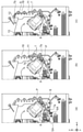
図4(a)~(c)は、第1カセット5Aに収容されているA4サイズの記録媒体Sが給送されるときの搬送経路を示す図である。第1カセット5A内の1番上に積載された記録媒体Sは、第1給送ユニット6Aによって2枚目以降の記録媒体から分離され、搬送ローラ7とピンチローラ7aにニップされながら、プラテン9と印刷ヘッド8の間の印刷領域Pに向けて搬送される。図4(a)は、記録媒体Sの先端が印刷領域Pに到達する直前の搬送状態を示す。記録媒体Sの進行方向は、第1給送ユニット6Aに給送されて印刷領域Pに到達する間に、水平方向(x方向)から、水平方向に対して約45度傾いた方向に変更される。
4 (a) to 4 (c) are diagrams showing a transport route when the A4 size recording medium S housed in the
印刷領域Pでは、印刷ヘッド8に設けられた複数の吐出口から記録媒体Sに向けてインクが吐出される。インクが付与される領域の記録媒体Sは、プラテン9によってその背面が支持されており、吐出口面8aと記録媒体Sの距離が一定に保たれている。インクが付与された後の記録媒体Sは、搬送ローラ7と拍車7bに案内されながら、先端が右に傾いているフラッパ11の左側を通り、ガイド18に沿って印刷装置1の鉛直方向上方へ搬送される。図4(b)は、記録媒体Sの先端が印刷領域Pを通過して鉛直方向上方に搬送される状態を示す。記録媒体Sの進行方向は、水平方向に対し約45度傾いた印刷領域Pの位置から、搬送ローラ7と拍車7bによって鉛直方向上方に変更されている。
In the print area P, ink is ejected toward the recording medium S from a plurality of ejection ports provided in the
記録媒体Sは、鉛直方向上方に搬送された後、排出ローラ12と拍車7bによって排出トレイ13に排出される。図4(c)は、記録媒体Sの先端が排出ローラ12を通過して排出トレイ13に排出される状態を示す。排出された記録媒体Sは、印刷ヘッド8によって画像が印刷された面を下にした状態で、排出トレイ13上に保持される。
The recording medium S is conveyed upward in the vertical direction and then discharged to the
次に、印刷ヘッド8に対するメンテナンス動作について説明する。図1でも説明したように、本実施形態のメンテナンスユニット16は、キャップユニット10とワイピングユニット17とを備え、所定のタイミングにこれらを作動させてメンテナンス動作を行う。
Next, the maintenance operation for the
図5は、印刷装置1がメンテナンス状態にあるときの印刷装置1の内部構成図である。印刷ヘッド8を図1に示す待機位置から図5に示すメンテナンス位置に移動する際、プリントコントローラ202は、印刷ヘッド8を鉛直方向において斜め上方に移動させるとともにキャップユニット10を鉛直方向下方に移動させる。そして、プリントコントローラ202は、ワイピングユニット17を退避位置から図5における右方向に移動させる。その後、プリントコントローラ202は、印刷ヘッド8を鉛直方向下方に移動させメンテナンス動作が可能なメンテナンス位置に移動させる。
FIG. 5 is an internal configuration diagram of the printing device 1 when the printing device 1 is in the maintenance state. When moving the
一方、印刷ヘッド8を図3に示す印刷位置から図5に示すメンテナンス位置に移動する際、プリントコントローラ202は、印刷ヘッド8を45度回転させつつ鉛直方向上方に移動させる。そして、プリントコントローラ202は、ワイピングユニット17を退避位置から右方向に移動させる。その後プリントコントローラ202は、印刷ヘッド8を鉛直方向下方に移動させて、メンテナンスユニット16によるメンテナンス動作が可能なメンテナンス位置に移動させる。
On the other hand, when the
印刷ヘッド8がメンテナンス位置に移動すると、キャップユニット10は、不図示のキャップ部材に予備吐出等で吐出されたインクを回収し、回収したインクを不図示の吸引ポンプに吸引させる。また、ワイピングユニット17は、吐出口面8aに付着するインクなどを拭き取る。このような、吸引処理及びワイピング処理により、メンテナンス動作が行われる。
When the
<フロントドア22のロック制御について>
図1、3及び7に示したプリント部2の内装構成は、外装(印刷装置1の筐体)で覆われており、当該外装は、開口部を開放する開放位置と開口部を覆う閉じ位置との間で回動可能な(開閉可能な)フロントドア22を有している。図17は、フロントドア22が開放位置に位置する状態における印刷装置1の外観を示した図である。フロントドア22が開放位置に位置するとユーザは、インクタンクユニット14に装着された各色インクタンクやMTC20、印刷ヘッド8等のプリント部2の内装に、開口部を介してアクセス可能になる。すなわち、ユーザは、プリント部2の内装の交換、修理、清掃等のメンテナンスを開口部を介して行うことができる。
<About lock control of the
The interior configuration of the printed
本実施形態では、後述のロック解除ボタンがユーザによって操作されるまで、フロントドア22がロックされており、開放できない(閉じ位置から移動することができない)状態となっている。ユーザは、フロントドア22を開放するためには、後述のロック解除ボタンを操作して、フロントドア22のロックを解除する必要がある。また、フロントドア22が開放されたあと、再び閉じ位置に戻った場合、フロントドア22は、再びロック状態となる。
In the present embodiment, the
なお、本実施形態の印刷装置1或いはホスト装置400の1以上の機能を実現するためのプログラムを、ネットワークや各種記憶媒体を介してシステム或いは装置に供給しても良い。そして、そのシステム或いは装置のコンピュータ(CPUやMPU等)がプログラムを読み出して機能を実行する、或いは各種機構に実行させるようにしてもよい。また、このプログラムは、1つのコンピュータで実行されても、複数のコンピュータの連動により実行されてもよい。加えて、上述した処理の全てをソフトウェアで実現する必要はなく、処理の一部または全部をASIC等のハードウェアで実現するようにしてもよい。さらには、1つのCPUで全ての処理を行う形態に限らず、複数のCPUが適宜連携をしながら処理を行う形態としてもよいし、いずれかの処理を1つのCPUが実行し、その他の処理を複数のCPUが連携しながら処理を行う形態としても良い。
A program for realizing one or more functions of the printing device 1 or the
上述したように、本実施形態では、フロントドア22が開放位置に位置する状態では、ユーザは、例えば、開口部に手を入れることで、プリント部2の内装を手で操作し、内装の交換、修理、清掃等のメンテナンスを行うことが可能となる。しかしながら、それらの内装は、印刷時やメンテナンス時等に動作中は、ユーザの操作を受け付けないことが好ましい。そのため、少なくともそれらの内装の動作中には、フロントドア22が開放されないように、フロントドア22がロックされていることが好ましい。
As described above, in the present embodiment, in the state where the
また、プリント部2の内装の交換前には、後述の準備処理が実行されることが好ましい。しかしながら、例えば、フロントドア22が常時ロックされていない形態では、準備処理が実行されていない状態でプリント部2の内装が交換されてしまうことがある。そのため、準備動作が実行されるまでは、フロントドア22がロックされていることが好ましい。一方で例えば、内装のメンテナンス処理を実行すべきタイミングに自動でフロントドア22のロックが解除され、準備処理が実行される形態では、ユーザが当該タイミングにおいてメンテナンス処理を実行しない場合にも準備処理が実行されてしまうことがある。すなわち、準備処理が無駄に実行されてしまうことがある。なお、準備処理には、不揮発性メモリへの書き込み処理等が含まれる。準備処理が無駄に実行されてしまうと、不揮発性メモリへの書き込み回数に制限がある(不揮発性メモリに書き込み寿命がある)場合には、不揮発性メモリの寿命を無駄に減らしてしまう。
Further, it is preferable that the preparation process described later is executed before the replacement of the interior of the printed
そこで本実施形態は、フロントドア22がロックされている形態とする。そして、フロントドア22のロックがユーザ操作無しに自動で解除されない構成とする。そして、フロントドア22を開放するためのユーザ操作が印刷装置1に対して行われたことが印刷装置1に特定されたことに基づいて、フロントドア22のロックが解除され、フロントドア22が開放可能となる形態とする。すなわち、ユーザ操作が行われたことを印刷装置1が特定することで、ユーザがプリント部2の内装のメンテナンスを開口部を介して行うタイミングを、印刷装置1が特定可能な形態とする。
Therefore, in this embodiment, the
なお、ここでは、ロック及びロック解除される開閉可能な構成(開閉部)が、フロントドア22である形態を説明したが、この形態に限定されない。例えば、ロック及びロック解除される開閉可能な構成が、印刷装置1から引き出し可能なトレイや引き出し等の構成であっても良い。この場合、当該構成が印刷装置1から引き出された状態が、当該構成が開放位置に位置する状態となり、当該構成が印刷装置1に押入れられた状態が、当該構成が閉じ位置に位置する状態となる。
Although the form in which the openable / closable configuration (opening / closing portion) to be locked and unlocked is the
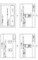
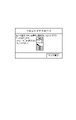
図6は、操作パネル104に表示される画面の一例を示す。図6(a)は、印刷装置1が備えるインクがなくなったエラーであるインク無しエラーが生じたことをユーザに通知するための画面の一例である。印刷装置1は、印刷動作やメンテナンス動作によってインクがなくなり、インク無しエラーが生じたことに基づいて、印刷動作やメンテナンス動作を中断して、図6(a)に示される画面を操作パネル104に表示する。なお、図6(a)に示される画面は、ブラックのインクとシアンのインクがなくなったエラーが生じたことを通知する画面の例である。図6(a)の画面における「次へ」ボタンがユーザによって押下されると、印刷装置1は、図6(b)に示すロック解除画面を操作パネル104に表示する。
FIG. 6 shows an example of a screen displayed on the
ロック解除画面は、フロントドア22を開放するためのユーザ操作(ロック解除操作)を受け付けるための画面である。このときロック解除画面が表示されるのは、ユーザは、インクタンクを交換するためには、フロントドア22を開放する(開放位置に移動させる)必要があるためである。
The unlock screen is a screen for accepting a user operation (unlock operation) for opening the
図6(b)の画面における「ロック解除」ボタンがユーザによって押下されると、まず印刷装置1は、フロントドア22のロックが解除される前且つインクタンクが交換される前に、インク交換準備処理を行う。インク交換準備処理は、インクタンクの不揮発性メモリ領域に、インクの残量の情報等のインクタンクに関連する情報の書き込みを行う処理を含む。また、インク交換準備処理は、インクタンクからインクを供給するための供給弁(不図示)を閉め、インクタンクを取り外しても、インク供給流路に空気が入り込まないようにする処理を含む。
When the "unlock" button on the screen of FIG. 6B is pressed by the user, the printing apparatus 1 first prepares for ink replacement before the
また、フロントドア22が開放されると、インクタンクだけでなく、MTCも交換されることが可能な状態となる。そのため、インク交換準備処理が実行される場合、MTC交換準備処理も実行される。MTC交換準備処理は、例えば、不揮発性メモリ領域に、MTCに含まれるインクの量の情報等の、MTCに関連する情報の書き込みを行う処理である。なお、図6(b)の画面における「ロック解除」ボタンが押下された場合には、後述のヘッド交換準備処理は実行されない。これは、図6(b)の画面における「ロック解除」ボタンが押下されたら、フロントドア22は開放されるが、印刷ヘッド8を覆うヘッドカバーが開放されたり、ヘッド交換位置に印刷ヘッド8が移動したりしないためである。
Further, when the
本実施形態では、インク交換準備処理及びMTC交換準備処理は、図6(b)の画面における「ロック解除」ボタンが押下されたことに基づいて実行される。また、各準備処理が終了した後に、フロントドア22のロックが解除される。そのため、各準備処理にかかる時間、フロントドア22のロックが解除されないことを通知する領域が、図6(b)の画面に含まれている。なお、各準備処理が開始されるタイミングや条件は上述の形態に限定されず、例えば、図6(a)の画面における「次へ」ボタンがユーザによって押下されたことや、インク無しエラーが生じたことに基づいて、各準備処理が開始されても良い。なお、図6(b)は、インクタンクの交換のためのロック解除画面であるため、画面上部には、インクタンクの交換を示す領域が含まれている。
In the present embodiment, the ink replacement preparation process and the MTC replacement preparation process are executed based on the fact that the "unlock" button on the screen of FIG. 6B is pressed. Further, after each preparation process is completed, the lock of the
図6(c)は、印刷ヘッド8の交換処理を実行するか否かをユーザに問う画面の一例である。ユーザは、印刷ヘッド8を交換したい任意のタイミングにおいて、操作パネル104に表示される印刷装置1の設定画面を操作することで、操作パネル104に図6(c)を表示させることができる。「いいえ」ボタンが押下されると、印刷装置1は、ヘッド交換準備処理を実行したり、図6(d)に示すロック解除画面を表示したりせず、操作パネル104に表示される画面を、図6(c)が表示される前に表示されていた設定画面に戻す。一方、「はい」ボタンが押下されると、印刷装置1は、図6(d)に示すロック解除画面を操作パネル104に表示する。
FIG. 6C is an example of a screen asking the user whether or not to execute the replacement process of the
図6(d)の画面における「ロック解除」ボタンがユーザによって押下されると、印刷装置1は、フロントドア22のロックが解除される前且つ印刷ヘッド8が交換される前に、ヘッド交換準備処理を行う。ヘッド交換準備処理とは、印刷ヘッド8内に残留しているインクをサブタンクに回収し、印刷ヘッド8に対してインクを供給するためのインク弁を閉め、印刷ヘッド8にインクが供給されない状態とする処理を含む。また、ヘッド交換準備処理は、印刷ヘッド8に配列されたノズルの使用履歴や、印刷ヘッド8の電源がオンとなった時間、印刷ヘッド8において発生したエラー等に関する情報を印刷ヘッド8の不揮発性メモリ領域に書き込む処理を含む。また、ヘッド交換準備処理は、印刷ヘッド8を交換するために開放が必要なヘッドカバーを開放する処理や、ヘッド交換位置に印刷ヘッド8を移動させる処理も含む。なおフロントドア22が開放されると、インクタンク及びMTCも交換されることが可能な状態となるため、ヘッド交換準備処理が実行される場合は、インク交換準備動作及びMTC交換準備動作も実行される。本実施形態では、各準備処理は、図6(d)の画面における「ロック解除」ボタンが押下されたことに基づいて実行される。また、各交換準備処理が終了した後に、フロントドア22のロックが解除される。そのため、各交換準備処理にかかる時間、フロントドア22のロックが解除されないことを通知する領域が、図6(d)の画面に含まれている。なお、ヘッド交換準備処理が開始されるタイミングや条件は上述の形態に限定されず、例えば、図6(c)の画面における「はい」ボタンがユーザによって押下されたことに基づいて、ヘッド交換準備処理が開始されても良い。また、例えば、図6(c)の画面が表示される前に表示された画面におけるユーザ操作に基づいて、ヘッド交換準備処理が開始されても良い。
When the "unlock" button on the screen of FIG. 6D is pressed by the user, the printing device 1 prepares for head replacement before the
このように、本実施形態では、フロントドア22を開放するためには、ユーザによるロック解除ボタンの押下を必要とする。そして、ロック解除に関わるユーザ操作が行われたことに基づいて、各種準備動作を行う。このような形態とすることで、例えば、ユーザによるフロントドア22の開放及び印刷装置1の内装のメンテナンスが行われないにもかかわらず、準備動作が実行されてしまうことを抑制できる。
As described above, in the present embodiment, in order to open the
なお、上述では、インクタンクの交換が、インクタンクに関するエラーが発生したときに行われる形態について説明したが、この形態に限定されない。インクタンクの交換が、上述のヘッド交換と同様、ユーザは、インクタンクを交換したい任意のタイミングにおいて、実行されても良い。すなわち、ユーザは、操作パネル104に表示される印刷装置1の設定画面を操作することで、任意のタイミングにおいて、印刷装置1に図6(b)の画面を表示させても良い。また、ヘッドの交換が、ヘッドに関するエラーが発生したときに行われても良い。すなわち、印刷装置1は、ヘッドに関するエラーが発生したことに基づいて、図6(c)や(d)の画面を表示しても良い。また、MTCに関するエラーが発生した場合や、ユーザがMTCを交換したい任意のタイミングにおいて操作パネル104に表示される印刷装置1の設定画面を操作した場合等に、MTCを交換するためのロック解除画面が表示されても良い。
In the above description, the form in which the ink tank is replaced when an error related to the ink tank occurs has been described, but the present invention is not limited to this form. The replacement of the ink tank may be performed at any time when the user wants to replace the ink tank, similar to the head replacement described above. That is, the user may display the screen of FIG. 6B on the printing device 1 at an arbitrary timing by operating the setting screen of the printing device 1 displayed on the
また、例えば、MTCに関するエラーとインクタンクに関するエラーが同時に発生した場合や、初期設定時等には、MTCとインクタンクの両方を交換する必要がある。その場合には、印刷装置1は、MTCを交換するためのロック解除画面と、インクタンクを交換するためのロック解除画面をそれぞれ異なるタイミングで表示する。具体的には例えば、印刷装置1は、まず、MTCを交換するためのロック解除画面を表示して、ユーザに、MTCの交換を促す。これにより、MTCが交換されて、フロントドア22が閉じられたら、印刷装置1は、フロントドア22をロックする。その後、印刷装置1は、インクタンクを交換するためのロック解除画面を表示し、ユーザに、インクタンクの交換を促す。なお、MTCの交換を先に促しているのは、インクタンクの交換時に流れるインクを、MTCが回収するためである。また、MTCを交換するためのロック解除画面によりフロントドア22が開放された時に、MTCだけでなく、インクタンクも交換されていた場合、印刷装置1は、インクタンクを交換するためのロック解除画面を表示しなくても良い。
Further, for example, when an error related to MTC and an error related to the ink tank occur at the same time, or at the time of initial setting, it is necessary to replace both the MTC and the ink tank. In that case, the printing apparatus 1 displays the unlock screen for replacing the MTC and the unlock screen for replacing the ink tank at different timings. Specifically, for example, the printing apparatus 1 first displays an unlock screen for replacing the MTC, and prompts the user to replace the MTC. As a result, when the MTC is replaced and the
また、ヘッド交換準備処理後に、印刷ヘッド8が交換され、フロントドア22がロックされた場合、印刷ヘッド8を使用するための準備処理が実行される。具体的には、インクタンクから印刷ヘッド8にインクを供給する。この準備処理に、インクタンクから供給されるインクと、インクタンクからのインク供給時に発生する廃インクを回収するMTCの残容量が必要となる。そのため、印刷装置1は、ヘッド交換準備処理前に、インクタンクが保持するインク残量と、MTCが保持可能な廃インクの残容量を確認し、インクタンク及びMTCに残量無しエラーが発生しているか否かを判定して良い。そして、残量無しエラーが発生していることが検知された場合、エラーが発生した構成を交換するために、インクタンクを交換するためのロック解除画面や、MTCを交換するためのロック解除画面を表示して良い。これにより、インクタンクやMTCが交換されて、インクタンク及びMTCに残量エラーが発生していないことが確認された後に、ヘッドを交換するためのロック解除画面が表示される。
Further, when the
また、ロック解除画面は、上述のように、エラー時や設定画面操作時だけでなく、他のタイミングにおいても表示されても良い。本実施形態では例えば、初期設定時や、輸送モード設定時等においてロック解除画面が表示される。 Further, as described above, the unlock screen may be displayed not only at the time of error or operation of the setting screen, but also at other timings. In the present embodiment, for example, the unlock screen is displayed at the time of initial setting, transportation mode setting, and the like.
なお、本実施形態では、ロック解除操作は、操作パネル104に表示されるソフトボタンに対する操作であったが、この形態に限定されない。例えば、印刷装置1が、ロック解除操作を受け付けるためのハードボタン等を備えていれば、ロック解除操作は、当該ハードボタンに対する操作であっても良い。なお、この形態の場合、例えば、印刷装置1による印刷中は、ハードボタンに対する操作が無効化される形態であっても良い。このように、ロック解除操作は、印刷装置1が備えるドア以外の構成に対して実行される操作であり、印刷装置1が検知可能な操作であれば良い。
In the present embodiment, the unlocking operation is an operation for the soft button displayed on the
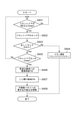
図7は、印刷装置1が実行するフロントドア22のロックを解除するための処理を示したフローチャートである。本フローチャートが示す処理は、図6(b)に示すロック解除画面において、ロック解除ボタンの押下が受け付けられた場合に開始される。また、本フローチャートが示す処理は、実際には、ROM107等のメモリに格納されたプログラムをメインコントローラ101がRAM106に読み出して実行することにより実現される。
FIG. 7 is a flowchart showing a process for unlocking the
S701では、印刷装置1は、インク交換準備処理を開始する。具体的にはまず、印刷装置1は、各インクタンクが備える不揮発メモリに、インクタンクに関連する情報を書き込む。 In S701, the printing apparatus 1 starts the ink replacement preparation process. Specifically, first, the printing apparatus 1 writes information related to the ink tank in the non-volatile memory included in each ink tank.
S702では、印刷装置1は、MTC交換準備処理を開始する。具体的にはまず、印刷装置1は、MTCが備える不揮発メモリにMTCに関連する情報を書き込む。 In S702, the printing apparatus 1 starts the MTC replacement preparation process. Specifically, first, the printing apparatus 1 writes information related to the MTC to the non-volatile memory included in the MTC.
S703では、印刷装置1は、各インクタンクが備える不揮発メモリ及び、MTCが備える不揮発メモリへの情報の書き込みを禁止する処理を実行する。これは、不揮発メモリに情報が書き込みされている状態で、インクタンクやMTCがユーザによって交換されることにより、書き込まれるデータに不具合が生じることを抑制するためである。 In S703, the printing apparatus 1 executes a process of prohibiting writing of information to the non-volatile memory included in each ink tank and the non-volatile memory included in the MTC. This is to prevent the written data from being defective due to the replacement of the ink tank and the MTC by the user while the information is written in the non-volatile memory.
S704では、印刷装置1は、供給弁をすべて閉じて、インクタンクを取り外しても、インク供給流路に空気が入り込まないようにする。 In S704, the printing apparatus 1 closes all the supply valves to prevent air from entering the ink supply flow path even if the ink tank is removed.
S705では、印刷装置1は、フロントドア22を開放可能な状態にするため、後述するこじ開け検知処理が実行されないように制御する。具体的には、印刷装置1は、こじ開け検知フラグをオフする。
In S705, the printing device 1 controls the
S706では、印刷装置1は、印刷装置1が備える所定の構成への電源供給を停止する。所定の構成とは具体的には、例えば、記録媒体の搬送に関わる構成(図4に示される構成)や、メンテナンス動作に関わる構成(ワイピングユニット17やメンテナンスユニット16、キャップユニット10)である。これにより、フロントドア22が開放されて、ユーザが印刷装置1の内部を操作している最中に、印刷動作や搬送動作、メンテナンス動作が実行されなくなるため、ユーザの安全性を向上できる。
In S706, the printing device 1 stops the power supply to the predetermined configuration included in the printing device 1. Specifically, the predetermined configuration is, for example, a configuration related to transport of a recording medium (configuration shown in FIG. 4) and a configuration related to maintenance operation (wiping
S707では、印刷装置1は、フロントドア22のロックを解除する。すなわち、印刷装置1は、フロントドア22を開放可能な状態に制御する。なお、このとき、印刷装置1は、フロントドア22のロックの解除だけでなく、フロントドア22の開放位置への移動も、自動で(ユーザ操作無しに)行っても良い。
In S707, the printing device 1 unlocks the
S708では、印刷装置1は、S707のロック解除処理後、フロントドア22のロックが正しく解除されたかを判定する。これは、フロントドアのロック機能をつかさどるロックモータの不具合等により、S707のロック解除処理が実行されても、正しくロックが解除されないことがあるためである。印刷装置は、YES判定の場合は、処理を終了し、NO判定の場合は、S709に進む。
In S708, the printing apparatus 1 determines whether or not the lock of the
S709では、印刷装置1は、フロントドア22のロック解除エラーが生じたこと(フロントドア22のロックが正しく解除されず、フロントドア22が開放可能な状態とならないこと)をユーザに通知する。具体的には、印刷装置1は、フロントドア22のロック解除エラーが生じたことを通知するための画面を、操作パネル104に表示する。印刷装置1は、その後処理を終了する。
In S709, the printing device 1 notifies the user that an unlocking error of the
なお、図6(d)に示すロック解除画面において、ロック解除ボタンの押下が受け付けられた場合には、例えば、S701の前に、ヘッド交換準備処理が開始される。なお、ヘッド交換準備処理は、MTC準備処理より後に実行されることが好ましい。これは、ヘッド交換準備処理において、印刷ヘッド8内に残留しているインクの排出処理等が行われる場合は、MTCが用いられることがあり、MTCが保持するインクが許容量を超えている状態ではヘッド交換準備処理が完了しないためである。また、S703において、さらに、印刷ヘッド8が備える不揮発性メモリに対する書き込みが禁止される。
When the unlock button is accepted on the unlock screen shown in FIG. 6 (d), the head replacement preparation process is started before, for example, S701. The head replacement preparation process is preferably executed after the MTC preparation process. This is a state in which MTC may be used when the ink remaining in the
なお、本実施形態では、S708の判定において、1回でもNO判定となったならば、S709にてエラー通知が行われる形態としたが、この形態に限定されない。NO判定となっても、S708の判定を繰り返しても良い。そして、所定回数NO判定が続いたならば、S709にてエラー通知が行われても良い。 In the present embodiment, if the determination of S708 is NO even once, the error notification is performed in S709, but the present invention is not limited to this embodiment. Even if the determination is NO, the determination of S708 may be repeated. Then, if the NO determination is continued a predetermined number of times, an error notification may be given in S709.
このように、本実施形態では、印刷装置1は、ユーザによってロック解除操作が実行されたことに基づいて、各種準備動作を実行する。このような形態とすることで、印刷装置1は、ユーザによる操作を受け付けることなく、自動で準備動作を実行する形態と比較して、無駄に準備動作を実行してしまうことを抑制できる。 As described above, in the present embodiment, the printing apparatus 1 executes various preparatory operations based on the unlocking operation being executed by the user. With such a form, the printing apparatus 1 can suppress the unnecessary execution of the preparatory operation as compared with the form in which the preparatory operation is automatically executed without accepting the operation by the user.
図8は、印刷装置1が実行するフロントドア22のロックをかけるための処理を示したフローチャートである。本フローチャートが示す処理は、フロントドア22が開放された(開放位置に移動した)後、再び閉じられた(閉じ位置に移動した)場合に開始される。具体的には、印刷装置1は、フロントドア22の開閉状態を検知可能な不図示の開閉センサを有しており、本フローチャートが示す処理は、開閉センサによりフロントドア22が閉じられたことが検知された場合に開始される。また、本フローチャートが示す処理は、実際には、ROM107等のメモリに格納されたプログラムをメインコントローラ101がRAM106に読み出して実行することにより実現される。
FIG. 8 is a flowchart showing a process for locking the
S801では、印刷装置1は、開閉センサから得られる出力に基づいて、フロントドア22が所定の時間(ここでは1秒)以上閉じられていたか(閉じ位置に位置したか)否かを判定する。印刷装置1は、YES判定の場合は、S802に進み、NO判定の場合は、再びS801の処理を行う。
In S801, the printing device 1 determines whether or not the
S802では、印刷装置1は、フロントドア22をロックする。すなわち、印刷装置1は、フロントドア22に対するユーザの手動操作では、フロントドア22が開放されないように制御する。
In S802, the printing device 1 locks the
S803では、印刷装置1は、フロントドア22が正しくロックされたか否かを判定する。これは、フロントドアのロック機能を司るロックモータの不具合等により、S802のロック処理が実行されても、正しくロックされないことがあるためである。印刷装置1は、YES判定の場合は、S805に進み、NO判定の場合は、S804の処理を行う。
In S803, the printing apparatus 1 determines whether or not the
S804では、印刷装置1は、フロントドア22のロックエラーが生じたこと(フロントドア22が正しくロックされず、フロントドア22が開放可能な状態となっていること)をユーザに通知する。具体的には、印刷装置1は、フロントドア22のロックエラーが生じたことを通知するための画面を、操作パネル104に表示する。印刷装置1は、その後処理を終了する。
In S804, the printing device 1 notifies the user that a lock error of the
S805では、印刷装置1は、開閉センサから得られる出力に基づいて、フロントドア22が閉じられているかどうかを判定する。これは、S801~S803の処理の間に、フロントドア22に対するユーザ操作等により、フロントドア22が開閉される可能性があるためである。印刷装置1は、YES判定の場合は、S806に進み、NO判定の場合は、再度フロントドア22が閉められたことを検知した後、再度S801の処理を行う。
In S805, the printing device 1 determines whether or not the
S806では、印刷装置1は、印刷装置1が備える所定の構成への電源供給を再開する。所定の構成とは具体的には、例えば、記録媒体の搬送に関わる構成(図4に示される構成)や、メンテナンス動作に関わる構成(ワイピングユニット17やメンテナンスユニット16、キャップユニット10)である。これにより、印刷装置1は、印刷動作や搬送動作、メンテナンス動作を再び実行可能となる。なお、例えば、ロック解除操作によりロックが解除されるドアがフロントドア22以外にも存在する場合は、それらのドアもロックされているか否かが検知されても良い。そして、全てのドアがロックされている場合に、電源供給の再開が行われても良い。
In S806, the printing device 1 resumes power supply to the predetermined configuration included in the printing device 1. Specifically, the predetermined configuration is, for example, a configuration related to transport of a recording medium (configuration shown in FIG. 4) and a configuration related to maintenance operation (wiping
S807では、印刷装置1は、後述するこじ開け検知処理が実行されるように制御する。具体的には、印刷装置1は、こじ開け検知フラグをオンする。 In S807, the printing apparatus 1 controls so that the prying open detection process described later is executed. Specifically, the printing device 1 turns on the prying open detection flag.
S808では、印刷装置1は、各インクタンクが備える不揮発メモリ及び、MTCが備える不揮発メモリへの情報の書き込みの禁止を解除する(書き込みを許可する)処理を実行する。その後、処理を終了する。 In S808, the printing apparatus 1 executes a process of releasing (permitting writing) the prohibition of writing information to the non-volatile memory included in each ink tank and the non-volatile memory included in the MTC. After that, the process ends.
なおこの後、例えば、インクタンクやMTC、印刷ヘッド8が正しく印刷装置1に装着されているか否かや、エラーが解除されたか否かが判定されても良い。そして、印刷装置1は、それらの判定がNO判定であった場合には、再度、ロック解除画面を表示しても良い。
After that, for example, it may be determined whether or not the ink tank, the MTC, and the
また上述では、S802において、印刷装置1がフロントドア22を自動でロックしていたが、この形態に限定されない。例えば、印刷装置1は、S802において図16に示すようなロック画面を表示し、ロック画面に対するロック操作がユーザによって行われた場合に、フロントドア22をロックしても良い。これは、フロントドア22が閉められたとしても、ユーザが再びフロントドア22を開けてメンテナンスを行う可能性があるためである。
Further, in the above description, in S802, the printing device 1 automatically locks the
<輸送準備処理について>
本実施形態では、印刷装置1は、印刷装置1が輸送される前のユーザの指示に従い、輸送準備処理を実行する。輸送準備処理とは、印刷装置1の輸送時における振動等に備えるための処理である。
<About transportation preparation processing>
In the present embodiment, the printing device 1 executes the transportation preparation process according to the instruction of the user before the printing device 1 is transported. The transportation preparation process is a process for preparing for vibration or the like during transportation of the printing apparatus 1.
図9は、印刷装置1が実行する輸送準備処理を示したフローチャートである。本フローチャートが示す処理は、不図示のメニュー画面に対する、輸送準備のためのユーザ操作が実行された場合に開始される。 FIG. 9 is a flowchart showing a transportation preparation process executed by the printing apparatus 1. The process shown in this flowchart is started when a user operation for transport preparation is executed for a menu screen (not shown).
S901では、印刷装置1は、印刷ヘッド8内及び、印刷ヘッド8へのインク供給経路内に残留しているインクを、サブタンク又はMTCへ移動させる。なお、輸送準備のためのユーザ操作として、輸送レベルを設定するための操作が含まれる可能性がある。輸送レベルとは、ユーザが実行しようとする輸送が、印刷装置1が長期間使用されなくなる輸送であるのか、印刷装置1が短期間使用されなくなる輸送であるのか、を設定するための処理である。前者の設定を、長期設定、後者の設定を短期設定という。S901におけるインクの移動は、輸送レベルの設定に応じて、異なる処理が実行されても良い。具体的には、印刷装置1は、輸送レベルが長期設定の場合には、印刷ヘッド8内及び、印刷ヘッド8へのインク供給経路内に残留しているすべてのインクをサブタンク又はMTCへ移動させても良い。そして、印刷装置1は、輸送レベルが短期設定の場合には、印刷ヘッド8内及び、印刷ヘッド8へのインク供給経路内に残留している一部のインクをサブタンク又はMTCへ移動させても良い。
In S901, the printing apparatus 1 moves the ink remaining in the
S902では、印刷装置1は、S901のインク移動処理でエラーが発生したか否かを判定する。インクを移動させるための構成に不具合がある場合には、印刷ヘッド8内及び、印刷ヘッド8へのインク供給経路内に残留しているインクを正常にサブタンク又はMTCへ移動させることができないエラーが生じる場合がある。具体的には例えば、サブタンク又はMTC内のインク量が許容量を超えた場合に、エラーが生じる。印刷装置1は、YES判定であれば、S903に進み、NO判定であれば、S904に進む。
In S902, the printing apparatus 1 determines whether or not an error has occurred in the ink transfer process of S901. If there is a problem with the configuration for moving the ink, there is an error that the ink remaining in the
S903では、印刷装置1は、インク移動処理でエラーが発生したことをユーザに通知する。具体的には例えば、印刷装置1は、インク移動処理でエラーが発生したことを通知するための画面を操作パネル104に表示する。その後、印刷装置1は、後述の設置フラグをオンせずに処理を終了する。なおこの時、エラーを解除させるために、ロック解除画面を表示して、ユーザにエラーを解除させても良い。
In S903, the printing apparatus 1 notifies the user that an error has occurred in the ink transfer process. Specifically, for example, the printing apparatus 1 displays a screen on the
S904では、印刷装置1は、設置フラグをオンにする。このフラグは、印刷装置1の電源がオンされた場合に、印刷装置1に参照されるフラグである。印刷装置は、電源オン時に参照する設置フラグがオンの場合には、後述の図15の画面を表示し、設置処理を実行する。一方、印刷装置は、電源オン時に参照する設置フラグがオフの場合には、印刷ヘッド8やインク供給経路内にインクを戻して、印刷を実行可能な状態に、設置処理を実行せずに戻る。
In S904, the printing apparatus 1 turns on the installation flag. This flag is a flag referred to by the printing device 1 when the power of the printing device 1 is turned on. When the installation flag referred to when the power is turned on is on, the printing device displays the screen of FIG. 15 described later and executes the installation process. On the other hand, when the installation flag referred to when the power is turned on is off, the printing device returns the ink to the
S905では、印刷装置1は、ロック解除画面を表示し、ユーザから、ロック解除操作を受け付ける。 In S905, the printing device 1 displays the unlock screen and accepts the unlock operation from the user.
S906では、印刷装置1は、図7に示したロック解除処理を実行する。ユーザは、S906によりフロントドア22のロックが解除されると、インクタンクやMTC、印刷ヘッド8の取り外しや、印刷ヘッド8が取り付けられるキャリッジを移動させないためのキャリッジ固定部材の取り付け等を行う。なお、印刷装置1は、ロック解除操作が受け付けられた場合、キャリッジ及び、キャリッジに取り付けらえている印刷ヘッド8を、キャリッジ固定部材の取り付けのための所定の位置に移動させてからロックを解除する。その後、印刷装置1は、ユーザによってフロントドア22が閉じられたことを検知する。
In S906, the printing apparatus 1 executes the unlocking process shown in FIG. 7. When the
S907では、印刷装置1は、図8に示したロック処理を実行する。 In S907, the printing apparatus 1 executes the lock process shown in FIG.
S908では、印刷装置1は、輸送準備が完了したか否かを判定する。具体的には印刷装置1は、インクタンクやMTC、印刷ヘッド8の取り外しや、印刷ヘッド8が取り付けられるキャリッジを移動させないためのキャリッジ固定部材の取り付け等が完了したか否かを判定する。印刷装置1は、YES判定の場合は処理を終了し、NO判定の場合は、S905の処理を再び実行する。
In S908, the printing apparatus 1 determines whether or not the transportation preparation is completed. Specifically, the printing apparatus 1 determines whether or not the removal of the ink tank, the MTC, and the
上述したように、印刷装置1は、電源がオンされた場合、設置フラグのオンオフを参照する。図9に示す輸送準備処理が完了した後、印刷装置1の電源が初めてオンされた場合は、設置フラグがオンになっている。そして、設置フラグがオンの状態においては、印刷装置1からインクタンクやMTC、印刷ヘッド8が取り外されており、さらに印刷装置1には、印刷ヘッド8が取り付けられるキャリッジを移動させないためのキャリッジ固定部材が取り付けられている。そのため、ユーザは、印刷装置1の機能を使用するためには、印刷装置1の初期設定を改めて実行する必要がある。そこで、印刷装置1は、参照した設置フラグがオンになっている場合、図15に示す初期設定画面を表示する。
As described above, the printing apparatus 1 refers to turning on / off the installation flag when the power is turned on. When the power of the printing apparatus 1 is turned on for the first time after the transportation preparation process shown in FIG. 9 is completed, the installation flag is turned on. When the installation flag is on, the ink tank, MTC, and
初期設定画面には、設置(初期設定)を実行するための領域や、印刷装置1のファームウエアのアップデートを実行するための領域、印刷装置1のネットワーク設定を実行するための領域、フロントドア22のロックを解除するための領域が含まれる。印刷装置1は、フロントドア22のロックを解除するための領域が操作されると、ロック解除画面を表示する。例えば、図9に示す準備処理の途中で(インクタンクやMTC、印刷ヘッド8の取り外し及びキャリッジ固定部材の取り付けが完了していない状態で)、印刷装置1の電源が切れてしまうことがある。その場合は、ユーザは、印刷装置1の電源オン後に、フロントドア22のロックを解除するための領域を押下し、フロントドア22を開放して、上述の準備処理の続きを行うことができる。
The initial setting screen includes an area for executing installation (initial setting), an area for executing firmware update of the printing device 1, an area for executing network setting of the printing device 1, and a
設置(初期設定)を実行するための領域がユーザによって押下された場合、印刷装置1は、ロック解除画面を表示する。そして印刷装置1は、ロック解除操作をユーザから受け付けたら、印刷装置1は、インクタンクやMTC、印刷ヘッド8の取り付けや、キャリッジ固定部材の取り外しを促す指示画面を操作パネル104に表示する。その後、印刷装置1は、ロック解除処理を実行する。ユーザは、指示画面に従って、フロントドア22を開放し、インクタンクやMTC、印刷ヘッド8の取り付けや、キャリッジ固定部材の取り外しを実行する。ユーザによってフロントドア22が閉められ、図8に示すロック処理が完了したら、印刷装置1は、インクタンクやMTC、印刷ヘッド8の取り付けや、キャリッジ固定部材の取り外しが完了したか否かを判定する。印刷装置1は、インクタンクやMTC、印刷ヘッド8の取り付けや、キャリッジ固定部材の取り外しが完了していない場合、再びロック解除画面を表示する。なお、このとき、印刷装置1は、インクタンクやMTC、印刷ヘッド8の取り付けや、キャリッジ固定部材の取り外しのうち完了していない処理の実行をユーザに指示しても良い。一方、印刷装置1は、インクタンクやMTC、印刷ヘッド8の取り付けや、キャリッジ固定部材の取り外しが完了している場合、印刷ヘッド8へのインクの充填等、印刷装置1の機能を利用可能とするための準備処理を実行する。これにより、印刷装置1は、輸送状態から回復し、各種機能(印刷やスキャン、コピー等)を実行可能となる。
When the area for executing the installation (initial setting) is pressed by the user, the printing device 1 displays the unlock screen. Then, when the printing device 1 receives the unlocking operation from the user, the printing device 1 displays an instruction screen on the
なお、初期設定画面は、例えば、印刷装置1が工場から出荷されてから初めて起動する場合等にも表示される。 The initial setting screen is also displayed, for example, when the printing apparatus 1 is started for the first time after being shipped from the factory.
<ロック中の警告処理(通知処理)について>
上述したように、印刷装置1は、ロック解除操作によりロックが解除されるまで、フロントドア22をロックし、フロントドア22に対するユーザの手動操作ではフロントドア22が開放されないようにしている。
<Warning processing (notification processing) during locking>
As described above, the printing device 1 locks the
しかしながら、フロントドア22がロックされていることを知らないユーザは、フロントドア22がロックされているにもかかわらず、フロントドア22を開放する操作(開放操作)をフロントドア22に対して実行する(こじ開け操作を実行する)ことがある。そして、こじ開け操作が続けられると、フロントドア22の破損等が生じる可能性がある。そこで、本実施形態では、こじ開け操作が行われたかどうかを検知するこじ開け検知処理を実行する。そして、こじ開け操作が行われたことが検知された場合は、ユーザに、フロントドア22がロックされていることを警告する処理を実行する。具体的には、印刷装置1は、こじ開け操作が行われた場合は、不図示のスピーカから警告音(通知音)を発する。また、印刷装置1は、フロントドア22がロックされていることを通知し、開放操作を実行しないように促すための、図11に示すような警告画面を操作パネル104に表示する。なお、その後、印刷装置1は、ロック解除画面を操作パネル104に表示しても良いし、ロック解除画面によってフロントドア22を開放することを促す画面を操作パネル104に表示しても良い。
However, a user who does not know that the
なお、本実施形態では、印刷装置1は、印刷装置1の状態に応じて、警告方法を異ならせるものとする。 In this embodiment, the printing device 1 has a different warning method depending on the state of the printing device 1.
図10は、印刷装置1が実行するこじ開け検知処理を示したフローチャートである。本フローチャートが示す処理は、フロントドア22がロックされた場合や、フロントドア22がロックされている状態で印刷装置1の電源がオンされた場合に開始される。また、本フローチャートが示す処理は、実際には、ROM107等のメモリに格納されたプログラムをメインコントローラ101がRAM106に読み出して実行することにより実現される。
FIG. 10 is a flowchart showing a prying open detection process executed by the printing apparatus 1. The process shown in this flowchart is started when the
S1001では、印刷装置1は、こじ開け検知処理が実行されるように制御されているかどうかを判定する。具体的には印刷装置1は、こじ開け検知フラグがオンになっているかどうかを判定する。印刷装置1は、YES判定の場合は、S1002に進み、NO判定の場合は、S1009の処理を行う。 In S1001, the printing apparatus 1 determines whether or not the prying open detection process is controlled to be executed. Specifically, the printing device 1 determines whether or not the prying open detection flag is turned on. The printing apparatus 1 proceeds to S1002 in the case of a YES determination, and performs the processing of S1009 in the case of a NO determination.
S1002では、印刷装置1は、フロントドア22がロックされているにもかかわらず、開放操作がフロントドア22に対してユーザによって行われた(こじ開け操作が行われた)か否かを判定する。印刷装置1には、フロントドア22が備える開閉ノブがつままれたことを検出する検出センサが備わっているものとする。印刷装置1は、検出センサから得られる出力により、こじ開け操作が行われたか否かを判定する。なお、印刷装置1は、例えば、上述の開閉センサにより、フロントドア22の微小な開放を検出することで、本判定を実行しても良い。印刷装置1は、YES判定の場合は、S1003に進み、NO判定の場合は、S1009の処理を行う。
In S1002, the printing apparatus 1 determines whether or not the opening operation is performed by the user on the front door 22 (pry opening operation is performed) even though the
S1003では、印刷装置1は、印刷装置1が機能実行中か否かを判定する。この時判定される機能は、例えば、印刷機能や、スキャン機能、コピー機能、メンテナンス機能等である。印刷装置1は、YES判定の場合は、S1004に進み、NO判定の場合は、S1005の処理を行う。 In S1003, the printing device 1 determines whether or not the printing device 1 is executing the function. The functions determined at this time are, for example, a print function, a scan function, a copy function, a maintenance function, and the like. If the determination is YES, the printing apparatus 1 proceeds to S1004, and if the determination is NO, the process of S1005 is performed.
S1004では、印刷装置1は、第1警告処理を実行する。第1警告処理とは、後述の第2警告処理時に発される警告音の音量より大きい音量で、警告音を発する処理及び、フロントドア22がロックされていることを通知し、こじ開け操作をやめるように促すための警告画面を操作パネル104に表示する処理である。なお、第1警告処理は、警告音を、後述の第2警告処理時における警告音の発生時間より長い時間発生する処理であっても良い。また、第1警告処理で表示される警告画面と、第2警告処理で表示される警告処理とが異なっていても良い。例えば、第1警告処理では、機能実行中におけるこじ開け操作をしないように警告するための、図12に示す警告画面が表示され、第2警告処理では、図11に示す警告画面が表示されるような形態でも良い。また、各警告画面は、所定の時間(例えば2秒)経過後に自動で表示されなくなる形態でも良いし、警告画面を閉じるためのユーザ操作に応じて表示されなくなる形態でも良いし、検出センサによりこじ開け操作が検知されている間のみ表示される形態でも良い。警告音の停止タイミングも同様である。
In S1004, the printing apparatus 1 executes the first warning process. The first warning process is a process of emitting a warning sound at a volume higher than the volume of the warning sound emitted during the second warning process described later, and notifies that the
S1005では、印刷装置1は、印刷装置1が省電力状態(スタンバイ状態)か否かを判定する。省電力状態とは、印刷装置1が備える少なくとも一部の構成に対して、電力の供給を停止したり、電力の供給を少なくしたりすることで、各種機能(印刷やスキャン、コピー)を実行可能な通常状態より消費電力が少なくなっている状態である。本実施形態では、省電力状態は、操作パネル104への電力供給を停止し、操作パネル104に画面を表示せず、さらに各種機能を実行しない状態であるものとする。印刷装置1は、YES判定の場合は、S1006に進み、NO判定の場合は、S1007の処理を行う。
In S1005, the printing device 1 determines whether or not the printing device 1 is in the power saving state (standby state). The power saving state is to execute various functions (printing, scanning, copying) by stopping the power supply or reducing the power supply for at least a part of the configurations included in the printing device 1. It is a state in which power consumption is lower than possible in a normal state. In the present embodiment, the power saving state is a state in which the power supply to the
S1006では、印刷装置1は、省電力状態から通常状態へ遷移する。すなわち、印刷装置1は、電力の供給を止めていた構成に対して、再び電力の供給を開始する。これにより、印刷装置1は、操作パネル104に画面を表示したり、警告音を発することが可能となる。
In S1006, the printing apparatus 1 transitions from the power saving state to the normal state. That is, the printing apparatus 1 starts supplying electric power again to the configuration in which the electric power supply has been stopped. As a result, the printing device 1 can display a screen on the
S1007では、印刷装置1は、ロック解除画面表示中かどうかを判定する。印刷装置1は、YES判定の場合は、S1006に進み、NO判定の場合は、S1007の処理を行う。なお、この判定において、さらに例えば、図6(a)のようなエラー通知画面や、図6(c)のような、交換画面表示中かどうかを判定しても良い。 In S1007, the printing device 1 determines whether or not the unlock screen is being displayed. The printing apparatus 1 proceeds to S1006 in the case of a YES determination, and performs the processing of S1007 in the case of a NO determination. In this determination, for example, it may be determined whether or not the error notification screen as shown in FIG. 6A or the exchange screen is being displayed as shown in FIG. 6C.
S1008では、印刷装置1は、第2警告処理を実行する。第2警告処理とは、第1警告処理時に発される警告音の音量より小さい音量で、警告音を発する処理及び、フロントドア22がロックされていることを通知し、こじ開け操作をやめるように促すための警告画面を操作パネル104に表示する処理である。なお、第2警告処理において、例えば、警告音を発する処理及び警告画面を表示する処理のうち一方が実行されなくても良い。
In S1008, the printing apparatus 1 executes the second warning process. The second warning process is a process that emits a warning sound at a volume smaller than the volume of the warning sound emitted during the first warning process, and notifies that the
S1009では、印刷装置1は、所定の時間(ここでは1秒)ウェイトして、再びS1001の処理を実行する。 In S1009, the printing apparatus 1 waits for a predetermined time (here, 1 second) and executes the process of S1001 again.
本フローチャートは、ロック解除操作によりロックが解除された場合に終了される。 This flowchart ends when the lock is released by the unlock operation.
このように、こじ開け操作が検知された場合には、ユーザに警告することで、こじ開け操作により印刷装置1が破損することを抑制できる。 As described above, when the prying open operation is detected, the user can be warned to prevent the printing apparatus 1 from being damaged by the prying open operation.
なお、例えば、警告処理を実行するか否かを設定可能な構成としても良い。例えば、印刷装置1は、設定画面に対する操作をユーザから受け付けることで、図13に示すような、警告設定画面を表示する。警告設定画面において、ユーザは、警告処理を実行するか否かの設定を実効可能である。ユーザによって、警告処理を実行することが設定されていた場合、フロントドア22が閉められた後、図10に示す警告処理が実行される。一方で、警告処理を実行しないことが設定されていた場合、フロントドア22が閉められた後、図10に示す警告処理が実行されない。すなわち、フロントドア22がロックされているにもかかわらず、開放操作がフロントドア22に対して実行されていても、警告画面を表示したり警告音を発生させたりしない。
In addition, for example, the configuration may be such that it is possible to set whether or not to execute the warning process. For example, the printing device 1 displays a warning setting screen as shown in FIG. 13 by receiving an operation on the setting screen from the user. On the warning setting screen, the user can effectively set whether or not to execute the warning processing. If the user has set to execute the warning process, the warning process shown in FIG. 10 is executed after the
また、例えば、S1003がYES判定である場合や、S1005がYES判定である場合に、第1警告処理と第2警告処理のうちいずれの警告処理を実行するかを、設定可能な構成としても良い。例えば、印刷装置1は、設定画面に対する操作をユーザから受け付けることで、図14に示すような、選択画面を表示する。S1003がYES判定である場合にいずれの警告処理を実行するかを設定するための領域が、画面上部の領域141である。一方、S1005がYES判定である場合にいずれの警告処理を実行するかを設定するための領域が、画面上部の領域142である。「強い」が選択された場合、第1警告処理が実行されるものとして設定され、「通常」が選択された場合、第2警告処理が実行されるものとして設定され、「なし」が選択された場合、いずれの警告処理も実行されないものとして設定される。すなわち、図10で示した処理は、S1003がYES判定である場合に実行される警告処理として、第1警告処理が設定されており、S1005がYES判定である場合に実行される警告処理として、第2警告処理が設定されている場合の処理である。
Further, for example, when S1003 is a YES determination or S1005 is a YES determination, it may be possible to set which of the first warning process and the second warning process is to be executed. .. For example, the printing device 1 displays a selection screen as shown in FIG. 14 by receiving an operation on the setting screen from the user. The
また、例えば、なお、警告画面が表示されている間や、警告音が発生されている間にこじ開けがさらに検知された場合、表示中の警告画面の表示時間や発生中の警告音の発生時間を長くしても良い。また、例えば、第2警告処理が実行されている間に、こじ開けがさらに検知された場合、警告のレベルを上げるべく、第1警告処理を新たに実行しても良い。 Further, for example, if the pry opening is further detected while the warning screen is displayed or the warning sound is being generated, the display time of the warning screen being displayed or the generation time of the warning sound being generated is generated. May be lengthened. Further, for example, if prying is further detected while the second warning process is being executed, the first warning process may be newly executed in order to raise the warning level.
また、例えば、こじ開け操作が所定の時間未満連続して実行されている状態では、第2警告処理を実行し、こじ開け操作が所定の時間以上連続して実行されている状態では、第1警告処理を実行しても良い。 Further, for example, when the prying open operation is continuously executed for less than a predetermined time, the second warning process is executed, and when the prying open operation is continuously executed for a predetermined time or longer, the first warning process is executed. May be executed.
なお、上述では、こじ開け時の印刷装置1の状態に応じて、警告の方法を切り替える形態について説明したが、この形態に限定されない。例えば、第2警告処理のみ実行される形態であってもよい。また、例えば、S1003やS1007の判定が省略されても良い。 In the above description, the mode of switching the warning method according to the state of the printing apparatus 1 at the time of prying open has been described, but the present invention is not limited to this mode. For example, it may be in a form in which only the second warning process is executed. Further, for example, the determination of S1003 or S1007 may be omitted.
また、上述では、ロック解除画面にユーザ操作が行われたら、フロントドア22のロックが解除される形態を説明したが、この形態に限定されない。例えば、印刷装置1による印刷実行中はフロントドア22がロックされ、印刷装置1による印刷が終了した場合に、フロントドア22のロックが解除される形態でも良い。
Further, in the above description, the mode in which the lock of the
1 印刷装置
22 フロントドア
1
Claims (21)
印刷部によって印刷を実行する印刷手段と、
前記印刷部を覆う筐体の一部である開閉可能な開閉部をロックするロック手段と、
前記開閉部がロックされている状態で、前記開閉部に対する、前記開閉部を開放するためのユーザ操作が実行された場合、所定の通知処理を実行する通知手段と、
前記開閉部に対する、前記開閉部を開放するためのユーザ操作が実行された場合、前記所定の通知処理を実行するか否かを設定する第1設定手段を有し、
前記開閉部がロックされている状態では、前記開閉部に対する前記開閉部を開けるためのユーザ操作が行われても、前記開閉部が開放されないことを特徴とする印刷装置。 It ’s a printing device.
A printing means that executes printing by the printing unit,
A locking means for locking an openable / closable opening / closing portion that is a part of a housing covering the printing portion.
When a user operation for opening the opening / closing portion is executed for the opening / closing portion while the opening / closing portion is locked, a notification means for executing a predetermined notification process and a notification means.
It has a first setting means for setting whether or not to execute the predetermined notification process when a user operation for opening the opening / closing unit is executed for the opening / closing unit .
A printing apparatus characterized in that, in a state where the opening / closing portion is locked, the opening / closing portion is not opened even if a user operation for opening the opening / closing portion is performed on the opening / closing portion.
印刷部によって印刷を実行する印刷手段と、A printing means that executes printing by the printing unit,
前記印刷部を覆う筐体の一部である開閉可能な開閉部をロックするロック手段と、A locking means for locking an openable / closable opening / closing portion that is a part of a housing covering the printing portion.
前記開閉部がロックされている状態で、前記開閉部に対する、前記開閉部を開放するためのユーザ操作が実行された場合、所定の通知処理を実行する通知手段と、When a user operation for opening the opening / closing portion is executed for the opening / closing portion while the opening / closing portion is locked, a notification means for executing a predetermined notification process and a notification means.
前記開閉部がロックされており、且つ前記印刷装置が、第1の状態よりも消費電力が低い第2の状態である状態において、前記開閉部に対する、前記開閉部を開放するためのユーザ操作が実行された場合、前記印刷装置を前記第2の状態から前記第1の状態に遷移させる遷移手段を有し、In a state where the opening / closing portion is locked and the printing device is in the second state in which the power consumption is lower than that in the first state, a user operation for opening the opening / closing portion is performed on the opening / closing portion. When executed, it has a transition means for transitioning the printing apparatus from the second state to the first state.
前記開閉部がロックされている状態では、前記開閉部に対する前記開閉部を開けるためのユーザ操作が行われても、前記開閉部が開放されず、In the state where the opening / closing portion is locked, even if a user operation for opening the opening / closing portion is performed on the opening / closing portion, the opening / closing portion is not opened.
前記開閉部がロックされており、且つ前記印刷装置が前記第2の状態である状態において、前記開閉部に対する、前記開閉部を開放するためのユーザ操作が実行された場合、前記印刷装置が前記第2の状態から前記第1の状態に遷移した後、前記通知処理が実行されることを特徴とする印刷装置。When the opening / closing section is locked and the printing device is in the second state, when a user operation for opening the opening / closing section is executed for the opening / closing section, the printing device is said to be said. A printing apparatus characterized in that the notification process is executed after the transition from the second state to the first state.
印刷部によって印刷を実行する印刷手段と、A printing means that executes printing by the printing unit,
前記印刷部を覆う筐体の一部である開閉可能な開閉部をロックするロック手段と、A locking means for locking an openable / closable opening / closing portion that is a part of a housing covering the printing portion.
前記開閉部がロックされている状態で、前記開閉部に対する、前記開閉部を開放するためのユーザ操作が実行された場合、所定の通知処理を実行する通知手段と、を有し、It has a notification means for executing a predetermined notification process when a user operation for opening the opening / closing portion is executed for the opening / closing portion in a state where the opening / closing portion is locked.
前記開閉部がロックされている状態では、前記開閉部に対する前記開閉部を開けるためのユーザ操作が行われても、前記開閉部が開放されず、In the state where the opening / closing portion is locked, even if a user operation for opening the opening / closing portion is performed on the opening / closing portion, the opening / closing portion is not opened.
前記開閉部がロックされており、且つ前記印刷装置が、第1の状態よりも消費電力が低い第2の状態である状態において、前記開閉部に対する、前記開閉部を開放するためのユーザ操作が実行された場合、前記所定の通知処理として、第1の通知処理が実行され、前記開閉部がロックされており、且つ前記印刷装置が前記第1の状態である状態において、前記開閉部に対する、前記開閉部を開放するためのユーザ操作が実行された場合、前記所定の通知処理として、前記第1の通知処理と異なる第2の通知処理が実行されることを特徴とする印刷装置。In a state where the opening / closing portion is locked and the printing device is in the second state in which the power consumption is lower than that in the first state, a user operation for opening the opening / closing portion is performed on the opening / closing portion. When executed, the first notification process is executed as the predetermined notification process, the opening / closing section is locked, and the printing device is in the first state, the opening / closing section is subjected to the first notification process. A printing apparatus characterized in that, when a user operation for opening the opening / closing unit is executed, a second notification process different from the first notification process is executed as the predetermined notification process.
印刷部によって印刷を実行する印刷手段と、A printing means that executes printing by the printing unit,
前記印刷部を覆う筐体の一部である開閉可能な開閉部をロックするロック手段と、A locking means for locking an openable / closable opening / closing portion that is a part of a housing covering the printing portion.
前記開閉部がロックされている状態で、前記開閉部に対する、前記開閉部を開放するためのユーザ操作が実行された場合、所定の通知処理を実行する通知手段と、を有し、It has a notification means for executing a predetermined notification process when a user operation for opening the opening / closing portion is executed for the opening / closing portion in a state where the opening / closing portion is locked.
前記開閉部がロックされている状態では、前記開閉部に対する前記開閉部を開けるためのユーザ操作が行われても、前記開閉部が開放されず、In the state where the opening / closing portion is locked, even if a user operation for opening the opening / closing portion is performed on the opening / closing portion, the opening / closing portion is not opened.
前記開閉部がロックされており、且つ前記印刷装置が印刷を実行中である状態において、前記開閉部に対する、前記開閉部を開放するためのユーザ操作が実行された場合、前記所定の通知処理として、第1の通知処理が実行され、前記開閉部がロックされており、且つ前記印刷装置が印刷を実行中でない状態において、前記開閉部に対する、前記開閉部を開放するためのユーザ操作が実行された場合、前記所定の通知処理として、前記第1の通知処理と異なる第2の通知処理が実行されることを特徴とする印刷装置。When the user operation for opening the opening / closing unit is executed for the opening / closing unit while the opening / closing unit is locked and the printing device is executing printing, the predetermined notification process is performed. , The first notification process is executed, the opening / closing part is locked, and the user operation for opening the opening / closing part is executed for the opening / closing part in a state where the printing device is not executing printing. If this is the case, the printing apparatus is characterized in that a second notification process different from the first notification process is executed as the predetermined notification process.
印刷部によって印刷を実行する印刷手段と、A printing means that executes printing by the printing unit,
前記印刷部を覆う筐体の一部である開閉可能な開閉部をロックするロック手段と、A locking means for locking an openable / closable opening / closing portion that is a part of a housing covering the printing portion.
前記開閉部がロックされている状態で、前記開閉部に対する、前記開閉部を開放するためのユーザ操作が実行された場合、所定の通知処理を実行する通知手段と、を有し、It has a notification means for executing a predetermined notification process when a user operation for opening the opening / closing portion is executed for the opening / closing portion in a state where the opening / closing portion is locked.
前記開閉部がロックされている状態では、前記開閉部に対する前記開閉部を開けるためのユーザ操作が行われても、前記開閉部が開放されず、In the state where the opening / closing portion is locked, even if a user operation for opening the opening / closing portion is performed on the opening / closing portion, the opening / closing portion is not opened.
前記開閉部がロックされている状態で、前記開閉部に対する、前記開閉部を開放するためのユーザ操作が、所定の時間以上連続して実行された場合、第1の通知処理が実行され、前記開閉部がロックされている状態で、前記開閉部に対する、前記開閉部を開放するためのユーザ操作が、所定の時間未満連続して実行された場合、前記第1の通知処理と異なる第2の通知処理が実行されることを特徴とする印刷装置。When the user operation for opening the opening / closing portion for the opening / closing portion is continuously executed for a predetermined time or longer while the opening / closing portion is locked, the first notification process is executed. When the user operation for opening the opening / closing portion for the opening / closing portion is continuously executed for less than a predetermined time while the opening / closing portion is locked, a second notification process different from the first notification process is performed. A printing device characterized in that notification processing is performed.
前記所定のユーザ操作が行われたことが検知された場合、前記開閉部のロックを解除する解除手段と、を更に有することを特徴とする請求項1乃至12のいずれか1項に記載の印刷装置。 A detection means for detecting that a predetermined user operation for unlocking the opening / closing portion has been performed on a predetermined configuration of the printing device other than the opening / closing portion while the opening / closing portion is locked. When,
The printing according to any one of claims 1 to 12 , further comprising an unlocking means for unlocking the opening / closing portion when it is detected that the predetermined user operation has been performed. Device.
Priority Applications (3)
| Application Number | Priority Date | Filing Date | Title |
|---|---|---|---|
| JP2018046012A JP6991899B2 (en) | 2018-03-13 | 2018-03-13 | Printing equipment, control methods and programs |
| US16/294,754 US10719278B2 (en) | 2018-03-13 | 2019-03-06 | Printing apparatus that performs notification processing according to the state of the printing apparatus |
| CN201910191272.7A CN110271279B (en) | 2018-03-13 | 2019-03-13 | Printing apparatus |
Applications Claiming Priority (1)
| Application Number | Priority Date | Filing Date | Title |
|---|---|---|---|
| JP2018046012A JP6991899B2 (en) | 2018-03-13 | 2018-03-13 | Printing equipment, control methods and programs |
Publications (3)
| Publication Number | Publication Date |
|---|---|
| JP2019155745A JP2019155745A (en) | 2019-09-19 |
| JP2019155745A5 JP2019155745A5 (en) | 2020-12-24 |
| JP6991899B2 true JP6991899B2 (en) | 2022-01-13 |
Family
ID=67903607
Family Applications (1)
| Application Number | Title | Priority Date | Filing Date |
|---|---|---|---|
| JP2018046012A Active JP6991899B2 (en) | 2018-03-13 | 2018-03-13 | Printing equipment, control methods and programs |
Country Status (3)
| Country | Link |
|---|---|
| US (1) | US10719278B2 (en) |
| JP (1) | JP6991899B2 (en) |
| CN (1) | CN110271279B (en) |
Families Citing this family (1)
| Publication number | Priority date | Publication date | Assignee | Title |
|---|---|---|---|---|
| JP7830886B2 (en) * | 2021-10-29 | 2026-03-17 | ブラザー工業株式会社 | printing device |
Citations (6)
| Publication number | Priority date | Publication date | Assignee | Title |
|---|---|---|---|---|
| JP2010194739A (en) | 2009-02-23 | 2010-09-09 | Canon Inc | Inkjet image forming apparatus and controlling method for the same |
| JP2011008142A (en) | 2009-06-29 | 2011-01-13 | Canon Inc | Image forming apparatus and method thereof |
| JP2013193416A (en) | 2012-03-22 | 2013-09-30 | Ricoh Co Ltd | Inkjet recording device and method of releasing cover lock of inkjet recording device |
| JP2014092631A (en) | 2012-11-01 | 2014-05-19 | Canon Inc | Image forming apparatus |
| US20170078508A1 (en) | 2015-09-10 | 2017-03-16 | Xerox Corporation | Secure document printer |
| JP2017072787A (en) | 2015-10-09 | 2017-04-13 | 京セラドキュメントソリューションズ株式会社 | Image forming apparatus |
Family Cites Families (9)
| Publication number | Priority date | Publication date | Assignee | Title |
|---|---|---|---|---|
| JP2006044128A (en) | 2004-08-06 | 2006-02-16 | Ricoh Co Ltd | Image forming apparatus |
| JP5010241B2 (en) * | 2006-11-02 | 2012-08-29 | 株式会社東芝 | Electromagnetic lock system for paper sheet processing device and stacking device |
| JP2008170865A (en) * | 2007-01-15 | 2008-07-24 | Kyocera Mita Corp | Image forming apparatus |
| JP4883079B2 (en) * | 2008-12-24 | 2012-02-22 | ブラザー工業株式会社 | Printing device |
| JP2010197566A (en) * | 2009-02-24 | 2010-09-09 | Fuji Xerox Co Ltd | Image forming apparatus, image forming system and program |
| JP5609392B2 (en) * | 2010-07-30 | 2014-10-22 | セイコーエプソン株式会社 | Printing control apparatus, printing apparatus, and printing control method in printing apparatus |
| JP5983253B2 (en) * | 2012-09-28 | 2016-08-31 | ブラザー工業株式会社 | Image forming apparatus |
| US9467583B2 (en) * | 2014-04-24 | 2016-10-11 | Xerox Corporation | System and method for semi-automatic generation of operating procedures from recorded troubleshooting sessions |
| JP6727957B2 (en) * | 2016-06-29 | 2020-07-22 | キヤノン株式会社 | Image forming device |
-
2018
- 2018-03-13 JP JP2018046012A patent/JP6991899B2/en active Active
-
2019
- 2019-03-06 US US16/294,754 patent/US10719278B2/en active Active
- 2019-03-13 CN CN201910191272.7A patent/CN110271279B/en active Active
Patent Citations (6)
| Publication number | Priority date | Publication date | Assignee | Title |
|---|---|---|---|---|
| JP2010194739A (en) | 2009-02-23 | 2010-09-09 | Canon Inc | Inkjet image forming apparatus and controlling method for the same |
| JP2011008142A (en) | 2009-06-29 | 2011-01-13 | Canon Inc | Image forming apparatus and method thereof |
| JP2013193416A (en) | 2012-03-22 | 2013-09-30 | Ricoh Co Ltd | Inkjet recording device and method of releasing cover lock of inkjet recording device |
| JP2014092631A (en) | 2012-11-01 | 2014-05-19 | Canon Inc | Image forming apparatus |
| US20170078508A1 (en) | 2015-09-10 | 2017-03-16 | Xerox Corporation | Secure document printer |
| JP2017072787A (en) | 2015-10-09 | 2017-04-13 | 京セラドキュメントソリューションズ株式会社 | Image forming apparatus |
Also Published As
| Publication number | Publication date |
|---|---|
| JP2019155745A (en) | 2019-09-19 |
| CN110271279A (en) | 2019-09-24 |
| US10719278B2 (en) | 2020-07-21 |
| CN110271279B (en) | 2021-07-09 |
| US20190286376A1 (en) | 2019-09-19 |
Similar Documents
| Publication | Publication Date | Title |
|---|---|---|
| JP2019014154A (en) | Inkjet recording device | |
| US11571908B2 (en) | Printing apparatus, control method and storage medium | |
| CN101462422A (en) | Printing apparatus and method of controlling printing apparatus | |
| US12145369B2 (en) | Image printing apparatus, control method of image printing apparatus and processing apparatus | |
| JP6991900B2 (en) | Printing equipment, control methods and programs | |
| JP2002331651A (en) | Ink jet recording device | |
| JP7034749B2 (en) | Recording device | |
| US20190283434A1 (en) | Printing apparatus and method for controlling the same | |
| JP6991899B2 (en) | Printing equipment, control methods and programs | |
| JP7171307B2 (en) | Liquid ejection device and control method | |
| JP2006044128A (en) | Image forming apparatus | |
| JP2006142608A (en) | Printing apparatus and printing control method | |
| JP7154797B2 (en) | INKJET RECORDING DEVICE AND METHOD OF CONTROLLING INKJET RECORDING DEVICE | |
| JP2020059128A (en) | Door lock controller and door lock control method | |
| JP7046589B2 (en) | Recording device | |
| JP2019038174A (en) | Recording device and control method of recording device | |
| JP4703389B2 (en) | Image forming apparatus | |
| JP2011104879A (en) | Image forming apparatus | |
| JP2002019223A (en) | Imaging apparatus | |
| JP2025056630A (en) | Recording device, method and program | |
| JP2025012725A (en) | Cartridge, cartridge set, and recording device | |
| JP2001180072A (en) | Recording device | |
| JP2019171837A (en) | Recording device | |
| JP2006213418A (en) | Sheet feeding apparatus and image forming apparatus | |
| JP2007130923A (en) | Printer device |
Legal Events
| Date | Code | Title | Description |
|---|---|---|---|
| A521 | Written amendment |
Free format text: JAPANESE INTERMEDIATE CODE: A523 Effective date: 20201102 |
|
| A621 | Written request for application examination |
Free format text: JAPANESE INTERMEDIATE CODE: A621 Effective date: 20201102 |
|
| A977 | Report on retrieval |
Free format text: JAPANESE INTERMEDIATE CODE: A971007 Effective date: 20210812 |
|
| A131 | Notification of reasons for refusal |
Free format text: JAPANESE INTERMEDIATE CODE: A131 Effective date: 20210824 |
|
| A521 | Written amendment |
Free format text: JAPANESE INTERMEDIATE CODE: A523 Effective date: 20211022 |
|
| TRDD | Decision of grant or rejection written | ||
| A01 | Written decision to grant a patent or to grant a registration (utility model) |
Free format text: JAPANESE INTERMEDIATE CODE: A01 Effective date: 20211109 |
|
| A61 | First payment of annual fees (during grant procedure) |
Free format text: JAPANESE INTERMEDIATE CODE: A61 Effective date: 20211208 |
|
| R151 | Written notification of patent or utility model registration |
Ref document number: 6991899 Country of ref document: JP Free format text: JAPANESE INTERMEDIATE CODE: R151 |