JP6991867B2 - Load control for bidirectional induction power transfer systems - Google Patents
Load control for bidirectional induction power transfer systems Download PDFInfo
- Publication number
- JP6991867B2 JP6991867B2 JP2018011056A JP2018011056A JP6991867B2 JP 6991867 B2 JP6991867 B2 JP 6991867B2 JP 2018011056 A JP2018011056 A JP 2018011056A JP 2018011056 A JP2018011056 A JP 2018011056A JP 6991867 B2 JP6991867 B2 JP 6991867B2
- Authority
- JP
- Japan
- Prior art keywords
- power
- primary
- ipt
- converter
- power converter
- Prior art date
- Legal status (The legal status is an assumption and is not a legal conclusion. Google has not performed a legal analysis and makes no representation as to the accuracy of the status listed.)
- Active
Links
Images


Classifications
-
- H—ELECTRICITY
- H02—GENERATION; CONVERSION OR DISTRIBUTION OF ELECTRIC POWER
- H02J—ELECTRIC POWER NETWORKS; CIRCUIT ARRANGEMENTS OR SYSTEMS FOR SUPPLYING OR DISTRIBUTING ELECTRIC POWER; SYSTEMS FOR STORING ELECTRIC ENERGY
- H02J50/00—Circuit arrangements or systems for wireless supply or distribution of electric power
- H02J50/90—Circuit arrangements or systems for wireless supply or distribution of electric power involving detection or optimisation of position, e.g. alignment
-
- B—PERFORMING OPERATIONS; TRANSPORTING
- B60—VEHICLES IN GENERAL
- B60L—PROPULSION OF ELECTRICALLY-PROPELLED VEHICLES; SUPPLYING ELECTRIC POWER FOR AUXILIARY EQUIPMENT OF ELECTRICALLY-PROPELLED VEHICLES; ELECTRODYNAMIC BRAKE SYSTEMS FOR VEHICLES IN GENERAL; MAGNETIC SUSPENSION OR LEVITATION FOR VEHICLES; MONITORING OPERATING VARIABLES OF ELECTRICALLY-PROPELLED VEHICLES; ELECTRIC SAFETY DEVICES FOR ELECTRICALLY-PROPELLED VEHICLES
- B60L53/00—Methods of charging batteries, specially adapted for electric vehicles; Charging stations or on-board charging equipment therefor; Exchange of energy storage elements in electric vehicles
- B60L53/10—Methods of charging batteries, specially adapted for electric vehicles; Charging stations or on-board charging equipment therefor; Exchange of energy storage elements in electric vehicles characterised by the energy transfer between the charging station and the vehicle
- B60L53/12—Inductive energy transfer
- B60L53/126—Methods for pairing a vehicle and a charging station, e.g. establishing a one-to-one relation between a wireless power transmitter and a wireless power receiver
-
- B—PERFORMING OPERATIONS; TRANSPORTING
- B60—VEHICLES IN GENERAL
- B60L—PROPULSION OF ELECTRICALLY-PROPELLED VEHICLES; SUPPLYING ELECTRIC POWER FOR AUXILIARY EQUIPMENT OF ELECTRICALLY-PROPELLED VEHICLES; ELECTRODYNAMIC BRAKE SYSTEMS FOR VEHICLES IN GENERAL; MAGNETIC SUSPENSION OR LEVITATION FOR VEHICLES; MONITORING OPERATING VARIABLES OF ELECTRICALLY-PROPELLED VEHICLES; ELECTRIC SAFETY DEVICES FOR ELECTRICALLY-PROPELLED VEHICLES
- B60L53/00—Methods of charging batteries, specially adapted for electric vehicles; Charging stations or on-board charging equipment therefor; Exchange of energy storage elements in electric vehicles
- B60L53/60—Monitoring or controlling charging stations
- B60L53/63—Monitoring or controlling charging stations in response to network capacity
-
- B—PERFORMING OPERATIONS; TRANSPORTING
- B60—VEHICLES IN GENERAL
- B60L—PROPULSION OF ELECTRICALLY-PROPELLED VEHICLES; SUPPLYING ELECTRIC POWER FOR AUXILIARY EQUIPMENT OF ELECTRICALLY-PROPELLED VEHICLES; ELECTRODYNAMIC BRAKE SYSTEMS FOR VEHICLES IN GENERAL; MAGNETIC SUSPENSION OR LEVITATION FOR VEHICLES; MONITORING OPERATING VARIABLES OF ELECTRICALLY-PROPELLED VEHICLES; ELECTRIC SAFETY DEVICES FOR ELECTRICALLY-PROPELLED VEHICLES
- B60L53/00—Methods of charging batteries, specially adapted for electric vehicles; Charging stations or on-board charging equipment therefor; Exchange of energy storage elements in electric vehicles
- B60L53/60—Monitoring or controlling charging stations
- B60L53/65—Monitoring or controlling charging stations involving identification of vehicles or their battery types
-
- B—PERFORMING OPERATIONS; TRANSPORTING
- B60—VEHICLES IN GENERAL
- B60L—PROPULSION OF ELECTRICALLY-PROPELLED VEHICLES; SUPPLYING ELECTRIC POWER FOR AUXILIARY EQUIPMENT OF ELECTRICALLY-PROPELLED VEHICLES; ELECTRODYNAMIC BRAKE SYSTEMS FOR VEHICLES IN GENERAL; MAGNETIC SUSPENSION OR LEVITATION FOR VEHICLES; MONITORING OPERATING VARIABLES OF ELECTRICALLY-PROPELLED VEHICLES; ELECTRIC SAFETY DEVICES FOR ELECTRICALLY-PROPELLED VEHICLES
- B60L55/00—Arrangements for supplying energy stored within a vehicle to a power network, i.e. vehicle-to-grid [V2G] arrangements
-
- H—ELECTRICITY
- H02—GENERATION; CONVERSION OR DISTRIBUTION OF ELECTRIC POWER
- H02J—ELECTRIC POWER NETWORKS; CIRCUIT ARRANGEMENTS OR SYSTEMS FOR SUPPLYING OR DISTRIBUTING ELECTRIC POWER; SYSTEMS FOR STORING ELECTRIC ENERGY
- H02J50/00—Circuit arrangements or systems for wireless supply or distribution of electric power
- H02J50/10—Circuit arrangements or systems for wireless supply or distribution of electric power using inductive coupling
- H02J50/12—Circuit arrangements or systems for wireless supply or distribution of electric power using inductive coupling of the resonant type
-
- H—ELECTRICITY
- H02—GENERATION; CONVERSION OR DISTRIBUTION OF ELECTRIC POWER
- H02M—APPARATUS FOR CONVERSION BETWEEN AC AND AC, BETWEEN AC AND DC, OR BETWEEN DC AND DC, AND FOR USE WITH MAINS OR SIMILAR POWER SUPPLY SYSTEMS; CONVERSION OF DC OR AC INPUT POWER INTO SURGE OUTPUT POWER; CONTROL OR REGULATION THEREOF
- H02M7/00—Conversion of AC power input into DC power output; Conversion of DC power input into AC power output
- H02M7/66—Conversion of AC power input into DC power output; Conversion of DC power input into AC power output with possibility of reversal
- H02M7/68—Conversion of AC power input into DC power output; Conversion of DC power input into AC power output with possibility of reversal by static converters
- H02M7/72—Conversion of AC power input into DC power output; Conversion of DC power input into AC power output with possibility of reversal by static converters using discharge tubes with control electrode or semiconductor devices with control electrode
- H02M7/79—Conversion of AC power input into DC power output; Conversion of DC power input into AC power output with possibility of reversal by static converters using discharge tubes with control electrode or semiconductor devices with control electrode using devices of a triode or transistor type requiring continuous application of a control signal
- H02M7/797—Conversion of AC power input into DC power output; Conversion of DC power input into AC power output with possibility of reversal by static converters using discharge tubes with control electrode or semiconductor devices with control electrode using devices of a triode or transistor type requiring continuous application of a control signal using semiconductor devices only
-
- H—ELECTRICITY
- H04—ELECTRIC COMMUNICATION TECHNIQUE
- H04B—TRANSMISSION
- H04B5/00—Near-field transmission systems, e.g. inductive or capacitive transmission systems
- H04B5/20—Near-field transmission systems, e.g. inductive or capacitive transmission systems characterised by the transmission technique; characterised by the transmission medium
- H04B5/24—Inductive coupling
-
- H—ELECTRICITY
- H04—ELECTRIC COMMUNICATION TECHNIQUE
- H04B—TRANSMISSION
- H04B5/00—Near-field transmission systems, e.g. inductive or capacitive transmission systems
- H04B5/70—Near-field transmission systems, e.g. inductive or capacitive transmission systems specially adapted for specific purposes
- H04B5/79—Near-field transmission systems, e.g. inductive or capacitive transmission systems specially adapted for specific purposes for data transfer in combination with power transfer
-
- B—PERFORMING OPERATIONS; TRANSPORTING
- B60—VEHICLES IN GENERAL
- B60L—PROPULSION OF ELECTRICALLY-PROPELLED VEHICLES; SUPPLYING ELECTRIC POWER FOR AUXILIARY EQUIPMENT OF ELECTRICALLY-PROPELLED VEHICLES; ELECTRODYNAMIC BRAKE SYSTEMS FOR VEHICLES IN GENERAL; MAGNETIC SUSPENSION OR LEVITATION FOR VEHICLES; MONITORING OPERATING VARIABLES OF ELECTRICALLY-PROPELLED VEHICLES; ELECTRIC SAFETY DEVICES FOR ELECTRICALLY-PROPELLED VEHICLES
- B60L2210/00—Converter types
- B60L2210/10—DC to DC converters
-
- B—PERFORMING OPERATIONS; TRANSPORTING
- B60—VEHICLES IN GENERAL
- B60L—PROPULSION OF ELECTRICALLY-PROPELLED VEHICLES; SUPPLYING ELECTRIC POWER FOR AUXILIARY EQUIPMENT OF ELECTRICALLY-PROPELLED VEHICLES; ELECTRODYNAMIC BRAKE SYSTEMS FOR VEHICLES IN GENERAL; MAGNETIC SUSPENSION OR LEVITATION FOR VEHICLES; MONITORING OPERATING VARIABLES OF ELECTRICALLY-PROPELLED VEHICLES; ELECTRIC SAFETY DEVICES FOR ELECTRICALLY-PROPELLED VEHICLES
- B60L2210/00—Converter types
- B60L2210/30—AC to DC converters
-
- B—PERFORMING OPERATIONS; TRANSPORTING
- B60—VEHICLES IN GENERAL
- B60L—PROPULSION OF ELECTRICALLY-PROPELLED VEHICLES; SUPPLYING ELECTRIC POWER FOR AUXILIARY EQUIPMENT OF ELECTRICALLY-PROPELLED VEHICLES; ELECTRODYNAMIC BRAKE SYSTEMS FOR VEHICLES IN GENERAL; MAGNETIC SUSPENSION OR LEVITATION FOR VEHICLES; MONITORING OPERATING VARIABLES OF ELECTRICALLY-PROPELLED VEHICLES; ELECTRIC SAFETY DEVICES FOR ELECTRICALLY-PROPELLED VEHICLES
- B60L2210/00—Converter types
- B60L2210/40—DC to AC converters
-
- H—ELECTRICITY
- H02—GENERATION; CONVERSION OR DISTRIBUTION OF ELECTRIC POWER
- H02M—APPARATUS FOR CONVERSION BETWEEN AC AND AC, BETWEEN AC AND DC, OR BETWEEN DC AND DC, AND FOR USE WITH MAINS OR SIMILAR POWER SUPPLY SYSTEMS; CONVERSION OF DC OR AC INPUT POWER INTO SURGE OUTPUT POWER; CONTROL OR REGULATION THEREOF
- H02M1/00—Details of apparatus for conversion
- H02M1/0067—Converter structures employing plural converter units, other than for parallel operation of the units on a single load
- H02M1/008—Plural converter units for generating at two or more independent and non-parallel outputs, e.g. systems with plural point of load switching regulators
-
- H—ELECTRICITY
- H02—GENERATION; CONVERSION OR DISTRIBUTION OF ELECTRIC POWER
- H02M—APPARATUS FOR CONVERSION BETWEEN AC AND AC, BETWEEN AC AND DC, OR BETWEEN DC AND DC, AND FOR USE WITH MAINS OR SIMILAR POWER SUPPLY SYSTEMS; CONVERSION OF DC OR AC INPUT POWER INTO SURGE OUTPUT POWER; CONTROL OR REGULATION THEREOF
- H02M7/00—Conversion of AC power input into DC power output; Conversion of DC power input into AC power output
- H02M7/42—Conversion of DC power input into AC power output without possibility of reversal
- H02M7/44—Conversion of DC power input into AC power output without possibility of reversal by static converters
- H02M7/48—Conversion of DC power input into AC power output without possibility of reversal by static converters using discharge tubes with control electrode or semiconductor devices with control electrode
- H02M7/4815—Resonant converters
-
- Y—GENERAL TAGGING OF NEW TECHNOLOGICAL DEVELOPMENTS; GENERAL TAGGING OF CROSS-SECTIONAL TECHNOLOGIES SPANNING OVER SEVERAL SECTIONS OF THE IPC; TECHNICAL SUBJECTS COVERED BY FORMER USPC CROSS-REFERENCE ART COLLECTIONS [XRACs] AND DIGESTS
- Y02—TECHNOLOGIES OR APPLICATIONS FOR MITIGATION OR ADAPTATION AGAINST CLIMATE CHANGE
- Y02E—REDUCTION OF GREENHOUSE GAS [GHG] EMISSIONS, RELATED TO ENERGY GENERATION, TRANSMISSION OR DISTRIBUTION
- Y02E60/00—Enabling technologies; Technologies with a potential or indirect contribution to GHG emissions mitigation
-
- Y—GENERAL TAGGING OF NEW TECHNOLOGICAL DEVELOPMENTS; GENERAL TAGGING OF CROSS-SECTIONAL TECHNOLOGIES SPANNING OVER SEVERAL SECTIONS OF THE IPC; TECHNICAL SUBJECTS COVERED BY FORMER USPC CROSS-REFERENCE ART COLLECTIONS [XRACs] AND DIGESTS
- Y02—TECHNOLOGIES OR APPLICATIONS FOR MITIGATION OR ADAPTATION AGAINST CLIMATE CHANGE
- Y02T—CLIMATE CHANGE MITIGATION TECHNOLOGIES RELATED TO TRANSPORTATION
- Y02T10/00—Road transport of goods or passengers
- Y02T10/60—Other road transportation technologies with climate change mitigation effect
- Y02T10/70—Energy storage systems for electromobility, e.g. batteries
-
- Y—GENERAL TAGGING OF NEW TECHNOLOGICAL DEVELOPMENTS; GENERAL TAGGING OF CROSS-SECTIONAL TECHNOLOGIES SPANNING OVER SEVERAL SECTIONS OF THE IPC; TECHNICAL SUBJECTS COVERED BY FORMER USPC CROSS-REFERENCE ART COLLECTIONS [XRACs] AND DIGESTS
- Y02—TECHNOLOGIES OR APPLICATIONS FOR MITIGATION OR ADAPTATION AGAINST CLIMATE CHANGE
- Y02T—CLIMATE CHANGE MITIGATION TECHNOLOGIES RELATED TO TRANSPORTATION
- Y02T10/00—Road transport of goods or passengers
- Y02T10/60—Other road transportation technologies with climate change mitigation effect
- Y02T10/7072—Electromobility specific charging systems or methods for batteries, ultracapacitors, supercapacitors or double-layer capacitors
-
- Y—GENERAL TAGGING OF NEW TECHNOLOGICAL DEVELOPMENTS; GENERAL TAGGING OF CROSS-SECTIONAL TECHNOLOGIES SPANNING OVER SEVERAL SECTIONS OF THE IPC; TECHNICAL SUBJECTS COVERED BY FORMER USPC CROSS-REFERENCE ART COLLECTIONS [XRACs] AND DIGESTS
- Y02—TECHNOLOGIES OR APPLICATIONS FOR MITIGATION OR ADAPTATION AGAINST CLIMATE CHANGE
- Y02T—CLIMATE CHANGE MITIGATION TECHNOLOGIES RELATED TO TRANSPORTATION
- Y02T10/00—Road transport of goods or passengers
- Y02T10/60—Other road transportation technologies with climate change mitigation effect
- Y02T10/72—Electric energy management in electromobility
-
- Y—GENERAL TAGGING OF NEW TECHNOLOGICAL DEVELOPMENTS; GENERAL TAGGING OF CROSS-SECTIONAL TECHNOLOGIES SPANNING OVER SEVERAL SECTIONS OF THE IPC; TECHNICAL SUBJECTS COVERED BY FORMER USPC CROSS-REFERENCE ART COLLECTIONS [XRACs] AND DIGESTS
- Y02—TECHNOLOGIES OR APPLICATIONS FOR MITIGATION OR ADAPTATION AGAINST CLIMATE CHANGE
- Y02T—CLIMATE CHANGE MITIGATION TECHNOLOGIES RELATED TO TRANSPORTATION
- Y02T90/00—Enabling technologies or technologies with a potential or indirect contribution to GHG emissions mitigation
- Y02T90/10—Technologies relating to charging of electric vehicles
- Y02T90/12—Electric charging stations
-
- Y—GENERAL TAGGING OF NEW TECHNOLOGICAL DEVELOPMENTS; GENERAL TAGGING OF CROSS-SECTIONAL TECHNOLOGIES SPANNING OVER SEVERAL SECTIONS OF THE IPC; TECHNICAL SUBJECTS COVERED BY FORMER USPC CROSS-REFERENCE ART COLLECTIONS [XRACs] AND DIGESTS
- Y02—TECHNOLOGIES OR APPLICATIONS FOR MITIGATION OR ADAPTATION AGAINST CLIMATE CHANGE
- Y02T—CLIMATE CHANGE MITIGATION TECHNOLOGIES RELATED TO TRANSPORTATION
- Y02T90/00—Enabling technologies or technologies with a potential or indirect contribution to GHG emissions mitigation
- Y02T90/10—Technologies relating to charging of electric vehicles
- Y02T90/14—Plug-in electric vehicles
-
- Y—GENERAL TAGGING OF NEW TECHNOLOGICAL DEVELOPMENTS; GENERAL TAGGING OF CROSS-SECTIONAL TECHNOLOGIES SPANNING OVER SEVERAL SECTIONS OF THE IPC; TECHNICAL SUBJECTS COVERED BY FORMER USPC CROSS-REFERENCE ART COLLECTIONS [XRACs] AND DIGESTS
- Y02—TECHNOLOGIES OR APPLICATIONS FOR MITIGATION OR ADAPTATION AGAINST CLIMATE CHANGE
- Y02T—CLIMATE CHANGE MITIGATION TECHNOLOGIES RELATED TO TRANSPORTATION
- Y02T90/00—Enabling technologies or technologies with a potential or indirect contribution to GHG emissions mitigation
- Y02T90/10—Technologies relating to charging of electric vehicles
- Y02T90/16—Information or communication technologies improving the operation of electric vehicles
- Y02T90/167—Systems integrating technologies related to power network operation and communication or information technologies for supporting the interoperability of electric or hybrid vehicles, i.e. smartgrids as interface for battery charging of electric vehicles [EV] or hybrid vehicles [HEV]
-
- Y—GENERAL TAGGING OF NEW TECHNOLOGICAL DEVELOPMENTS; GENERAL TAGGING OF CROSS-SECTIONAL TECHNOLOGIES SPANNING OVER SEVERAL SECTIONS OF THE IPC; TECHNICAL SUBJECTS COVERED BY FORMER USPC CROSS-REFERENCE ART COLLECTIONS [XRACs] AND DIGESTS
- Y04—INFORMATION OR COMMUNICATION TECHNOLOGIES HAVING AN IMPACT ON OTHER TECHNOLOGY AREAS
- Y04S—SYSTEMS INTEGRATING TECHNOLOGIES RELATED TO POWER NETWORK OPERATION, COMMUNICATION OR INFORMATION TECHNOLOGIES FOR IMPROVING THE ELECTRICAL POWER GENERATION, TRANSMISSION, DISTRIBUTION, MANAGEMENT OR USAGE, i.e. SMART GRIDS
- Y04S10/00—Systems supporting electrical power generation, transmission or distribution
- Y04S10/12—Monitoring or controlling equipment for energy generation units, e.g. distributed energy generation [DER] or load-side generation
- Y04S10/126—Monitoring or controlling equipment for energy generation units, e.g. distributed energy generation [DER] or load-side generation the energy generation units being or involving electric vehicles [EV] or hybrid vehicles [HEV], i.e. power aggregation of EV or HEV, vehicle to grid arrangements [V2G]
-
- Y—GENERAL TAGGING OF NEW TECHNOLOGICAL DEVELOPMENTS; GENERAL TAGGING OF CROSS-SECTIONAL TECHNOLOGIES SPANNING OVER SEVERAL SECTIONS OF THE IPC; TECHNICAL SUBJECTS COVERED BY FORMER USPC CROSS-REFERENCE ART COLLECTIONS [XRACs] AND DIGESTS
- Y04—INFORMATION OR COMMUNICATION TECHNOLOGIES HAVING AN IMPACT ON OTHER TECHNOLOGY AREAS
- Y04S—SYSTEMS INTEGRATING TECHNOLOGIES RELATED TO POWER NETWORK OPERATION, COMMUNICATION OR INFORMATION TECHNOLOGIES FOR IMPROVING THE ELECTRICAL POWER GENERATION, TRANSMISSION, DISTRIBUTION, MANAGEMENT OR USAGE, i.e. SMART GRIDS
- Y04S30/00—Systems supporting specific end-user applications in the sector of transportation
- Y04S30/10—Systems supporting the interoperability of electric or hybrid vehicles
- Y04S30/14—Details associated with the interoperability, e.g. vehicle recognition, authentication, identification or billing
Landscapes
- Engineering & Computer Science (AREA)
- Power Engineering (AREA)
- Computer Networks & Wireless Communication (AREA)
- Transportation (AREA)
- Mechanical Engineering (AREA)
- Signal Processing (AREA)
- Inverter Devices (AREA)
- Ac-Ac Conversion (AREA)
- Electric Propulsion And Braking For Vehicles (AREA)
Description
本発明は、誘導電力伝送(IPT)システムにおける負荷を平衡化するための方法およ
び装置に関する。本発明は、双方向マルチピックアップIPTシステムに特に適している
が、単方向および/またはシングルピックアップシステムにも使用することができる。
The present invention relates to methods and devices for balancing loads in an inductive power transfer (IPT) system. The present invention is particularly suitable for bidirectional multi-pickup IPT systems, but can also be used for unidirectional and / or single pickup systems.
誘導電力伝送(IPT)システムは、複数の用途で知られ、使用されている。IPT技
術は、効率が高く(通常は85~90%)、劣悪な環境で動作可能であり、埃および湿気
による影響を受けない。
Inductive power transfer (IPT) systems are known and used in multiple applications. IPT technology is highly efficient (usually 85-90%), can operate in harsh environments, and is unaffected by dust and moisture.
典型的なIPTシステムは、3つの主な構成要素、すなわち、AC電源と、電源に電気
結合されたプライマリ導電経路、コイルまたはパッドと、使用時に負荷に動力を供給する
ためのプライマリ巻線に誘導結合される少なくとも1つの電気的に分離したピックアップ
とで構成される。一般に、電源およびプライマリ巻線は、IPTシステムのプライマリ側
、ピックアップおよび関連する負荷は、システムのセカンダリ側と呼ばれる。
A typical IPT system is guided to three main components: an AC power source, a primary conductive path electrically coupled to the power source, a coil or pad, and a primary winding to power the load during use. It consists of at least one electrically separated pickup that is coupled. Generally, the power supply and primary windings are referred to as the primary side of the IPT system, and the pickups and associated loads are referred to as the secondary side of the system.
従来、電源が、電源回路網(一般に「グリッド」と呼ばれる)に電気結合されており、
グリッドから負荷への非接触単方向電力伝送のため、プライマリ巻線にエネルギー供給す
るために使用される。ACまたはグリッド電源からのコンバータによってプライマリ巻線
にエネルギー供給して、プライマリ巻線中に高周波AC電流が生成され、その結果、プラ
イマリ巻線の周りに継続的に変化する磁界が発生する。エアギャップによってプライマリ
巻線から離隔したそのまたは各々のピックアップは、ファラデーの電磁誘導の法則にした
がってコイルを通過する磁束を変化させることによって電圧が誘起され、それにより非接
触電力伝送を達成するコイルを含む。
Traditionally, power supplies are electrically coupled to a power network (commonly referred to as a "grid").
Used to supply energy to the primary winding for non-contact unidirectional power transfer from the grid to the load. A converter from AC or grid power supplies energy to the primary winding to generate a high frequency AC current in the primary winding, resulting in a continuously changing magnetic field around the primary winding. Its or each pickup, separated from the primary winding by an air gap, induces a voltage by varying the magnetic flux passing through the coil according to Faraday's law of electromagnetic induction, thereby providing a coil that achieves non-contact power transfer. include.
一般に、電力を供給するのはプライマリ側のみであるので、単方向IPTシステムにお
ける電力潮流を制御するためには、プライマリ側のインバータとして働くコンバータと、
ピックアップ側の単純なスイッチモードレギュレータとで十分である。
Generally, power is supplied only to the primary side, so in order to control the power flow in a unidirectional IPT system, a converter that works as an inverter on the primary side and a converter
A simple switch mode regulator on the pickup side is sufficient.
双方向IPTシステムは、例えば、グリッドに対する負荷を平衡化することを目的とす
る「非接触」二方向電力伝送が望ましい電気自動車(EV)システムおよびビークルツー
グリッド(V2G)システムのような適用例には理想的である。
Bidirectional IPT systems are used, for example, in applications such as electric vehicle (EV) systems and vehicle-to-grid (V2G) systems where "non-contact" two-way power transmission is desired to balance the load on the grid. Is ideal.
しかしながら、双方向IPTシステムの電力潮流は、単方向システムと比較してより洗
練された制御策を使用して調整されていなければならない。
However, the power flow of a bidirectional IPT system must be tuned using more sophisticated controls compared to a unidirectional system.
単方向IPTシステムとは対照的に、双方向IPTシステムのプライマリ側とピックア
ップ側の両方は、ソースまたはシンクにいずれかとして働くように構成されなければなら
ない。したがって、電力潮流の方向に応じて、AC-DC電力変換またはDC-AC電力
変換を容易にするために、システムの両側に同一または同様のコンバータトポロジーが必
要とされる。
In contrast to unidirectional IPT systems, both the primary and pickup sides of a bidirectional IPT system must be configured to act as either a source or a sink. Therefore, the same or similar converter topologies are required on both sides of the system to facilitate AC-DC power conversion or DC-AC power conversion, depending on the direction of the power flow.
任意の所与の電力レベルについてのコンバータのVA定格を最小限に抑えるために、並
列補償または直列補償は、通常、プライマリおよびピックアップのコイルインダクタンス
を提供する。したがって、双方向IPTシステムは、高次共振回路網であり、より洗練さ
れたロバストな制御を必要とする。
In order to minimize the converter's VA rating for any given power level, parallel or series compensation typically provides primary and pickup coil inductance. Therefore, the bidirectional IPT system is a high-order resonant network and requires more sophisticated and robust control.
電力潮流の量および方向は通常、専用のコントローラを使用して、コンバータによって
生成された電圧の相対位相または大きさのいずれかの制御によって制御される。しかしな
がら、ロバストな機構には、その電力定格を超えることなく、一方側からの電力需要を供
給側によって満たすことができることを保証することが不可欠である。
The amount and direction of power flow is typically controlled by controlling either the relative phase or magnitude of the voltage generated by the converter using a dedicated controller. However, it is essential for a robust mechanism to ensure that the supply side can meet the power demand from one side without exceeding its power rating.
並列補償型IPTシステムにおいて採用されるコンバータは、当然、電流源として挙動
する。そのようなシステムにおいて、ソース側の動作をその最大電力レベルまたは定格電
力レベルに制限することは、特に、ピックアップの需要がソース側コンバータの電力処理
能力を超えるときには、常に課題が多かった。主要な例は、2つの側の間の磁気結合が改
善するとき、あるいは、電気自動車(EV)が充電ベイで充電される場合の様に電力需要
が変化するピックアップに単一のプライマリコンバータによって応じるべきときに生じる
。その上、複数のピックアップの間で電力伝達の共有することおよび優先順位を付けるこ
ともまた、任意の所与の入力電力についての課題と見なされ得る。
The converter used in the parallel compensation IPT system naturally behaves as a current source. In such systems, limiting source-side operation to its maximum or rated power level has always been a challenge, especially when the demand for pickups exceeds the power processing capacity of the source-side converter. The main example responds to pickups with changing power demands, such as when the magnetic coupling between the two sides improves, or when an electric vehicle (EV) is charged in the charging bay, with a single primary converter. Occurs when it should. Moreover, sharing and prioritizing power transfer among multiple pickups can also be considered a challenge for any given input power.
プライマリよって供給される電力は、過度な電力需要が検出されると、プライマリコイ
ルまたはトラック電流を低下させることによって制限され得る。しかし、この方策は、他
のピックアップへの電力送達を損なうので、マルチピックアップIPTシステムに適さな
い。その上、より低いトラック電流を使用するシングルピックアップIPTシステムは、
比較的高いQ係数で動作し、循環エネルギーの増加につながり、システムは構成要素許容
差をより受けやすくなる。
The power supplied by the primary can be limited by reducing the primary coil or track current when excessive power demand is detected. However, this measure impairs power delivery to other pickups and is not suitable for multi-pickup IPT systems. Moreover, single pickup IPT systems that use lower track currents
It operates with a relatively high Q factor, leading to an increase in circulating energy, making the system more susceptible to component tolerances.
代替的な解決策は、プライマリ側と、1つのピックアップまたは複数のピックアップの
それぞれとの間で、専用のワイヤレス通信インターフェースを採用することである。次い
で、プライマリの最大電力能力を、ワイヤレスインターフェースを介してピックアップに
リレーすることができ、パワーインテークが制限されなければならないことが必要となる
。しかしながら、そのようなワイヤレスインターフェースは、追加のハードウェアおよび
ソフトウェアを必要とするので、構成要素数および複雑性に関して明らかにコストがかか
る。
An alternative solution is to employ a dedicated wireless communication interface between the primary side and each of one pickup or multiple pickups. It is then necessary that the maximum power capacity of the primary can be relayed to the pickup via the wireless interface and the power intake must be limited. However, such wireless interfaces require additional hardware and software, which is clearly costly in terms of component number and complexity.
したがって、本発明の目的は、従来技術の1以上の課題を克服するまたは改善する方法
および/または装置を提供すること、あるいは少なくとも、有用な選択肢を公に提供する
ことである。
Accordingly, it is an object of the present invention to provide a method and / or device for overcoming or ameliorating one or more of the problems of the prior art, or at least publicly providing useful options.
本発明のさらなる目的は、以下の記載から明らかになるであろう。 Further objections of the present invention will become clear from the following description.
第1の態様において、本発明は、広範には、プライマリ側とセカンダリ側とを有する誘
導電力伝送(IPT)システムにおいて使用するための負荷制御方法にあると言うことが
でき、当該方法は、
プライマリ側において、プライマリ側とセカンダリ側との間の電力伝送を感知するステ
ップと、
電力伝送とプライマリ側の力の給電能力との差に比例して、プライマリ側の電力変換装
置の動作周波数を同調周波数に対して変化させるステップと、
セカンダリ側において、動作周波数の前記変化を感知するステップと、
セカンダリ側において、プライマリ側の給電能力を超えないように、動作周波数の前記
変化に比例して前記電力伝送を調整するステップと、
を含む。
In a first aspect, the invention can be broadly referred to as a load control method for use in an inductive power transfer (IPT) system having a primary side and a secondary side.
On the primary side, the step of sensing power transfer between the primary side and the secondary side,
A step of changing the operating frequency of the power converter on the primary side with respect to the tuning frequency in proportion to the difference between the power transmission and the power supply capacity of the power on the primary side.
On the secondary side, the step of sensing the change in the operating frequency and
On the secondary side, a step of adjusting the power transmission in proportion to the change in the operating frequency so as not to exceed the power supply capacity of the primary side, and
including.
好ましくは、動作周波数を変化させるステップは、動作周波数を一連の増分ステップで
変化させることを含む。
Preferably, the step of changing the operating frequency comprises changing the operating frequency in a series of incremental steps.
好ましくは、動作周波数を変化させるステップは、動作周波数を周期的に変化させるこ
とを含む。
Preferably, the step of changing the operating frequency comprises periodically changing the operating frequency.
好ましくは、前記動作周波数は、前記周期的変化の全期間にわたって維持される。 Preferably, the operating frequency is maintained over the entire period of the periodic change.
代替的には、前記動作周波数は、各期間の一部では維持され、当該ステップが、各期間
の残りの部分では同調周波数に戻ることを含む。
Alternatively, said operating frequency is maintained for part of each period, and the step includes returning to the tuning frequency for the rest of each period.
好ましくは、同調周波数は、プライマリ側とセカンダリ側との両者の共振回路が同調さ
れる周波数である。
Preferably, the tuning frequency is the frequency at which both the primary and secondary resonant circuits are tuned.
好ましくは、同調周波数は、10kHz~100kHzである。 Preferably, the tuning frequency is 10 kHz to 100 kHz.
好ましくは、同調周波数は、同調周波数の所定の範囲内で変化する。 Preferably, the tuning frequency varies within a predetermined range of tuning frequencies.
好ましくは、この所定の範囲は、コンバータのVA定格を最小限に抑えるために、実質
的に±1kHzまたは同様の範囲である。
Preferably, this predetermined range is substantially ± 1 kHz or a similar range in order to minimize the VA rating of the converter.
第2の態様において、本発明は、広範には、誘導電力伝送(IPT)システムのプライ
マリ側電力コンバータにおいて使用するための制御方法にあると言うことができ、当該方
法は、
使用時に、プライマリ側電力コンバータとプライマリ側電力コンバータを誘導結合可能
な1以上のIPTピックアップとの間の電力伝送を感知するステップと、
電力伝送とプライマリ側電力コンバータの給電能力との差に比例して、プライマリ側電
力コンバータの動作周波数を同調周波数に対して変化させ、それにより、前記ピックアッ
プのそれぞれによって前記変化が感知され、前記電力伝送が調整される、ステップと、
を含む。
In a second aspect, the invention can be broadly referred to as a control method for use in a primary side power converter of an inductive power transfer (IPT) system.
In use, the step of sensing power transfer between the primary power converter and one or more IPT pickups that can inductively couple the primary power converter,
The operating frequency of the primary power converter is changed relative to the tuning frequency in proportion to the difference between the power transfer and the power supply capacity of the primary power converter, whereby the change is sensed by each of the pickups and the power Transmission is adjusted, steps and
including.
好ましくは、動作周波数を変化させるためのステップは、動作周波数を増分ステップで
変化させることを含む。
Preferably, the step for changing the operating frequency involves changing the operating frequency in incremental steps.
好ましくは、動作周波数を変化させるステップは、動作周波数を周期的に変化させるこ
とを含む。
Preferably, the step of changing the operating frequency comprises periodically changing the operating frequency.
好ましくは、動作周波数を変化させるステップは、各期間の一部では動作周波数を維持
することと、各期間の残りの部分では同調周波数に戻ることとを含む。
Preferably, the step of changing the operating frequency involves maintaining the operating frequency for part of each period and returning to the tuning frequency for the rest of each period.
好ましくは、同調周波数は、プライマリ側とセカンダリ側との両者の共振回路が同調さ
れる周波数である。
Preferably, the tuning frequency is the frequency at which both the primary and secondary resonant circuits are tuned.
好ましくは、当該方法は、電力伝送を継続的に監視することを含む。 Preferably, the method comprises continuously monitoring power transmission.
代替的には、当該方法は、電力伝送を周期的に監視するステップを含む。 Alternatively, the method comprises the step of periodically monitoring the power transfer.
好ましくは、当該方法は、動作周波数を同調周波数の所定の範囲内で変化させるステッ
プを含む。
Preferably, the method comprises changing the operating frequency within a predetermined range of the tuning frequency.
好ましくは、当該方法は、プライマリ側電力コンバータを一定のトラック電流に調整す
るステップをさらに含む。
Preferably, the method further comprises adjusting the primary power converter to a constant track current.
好ましくは、プライマリ側電力コンバータを調整するステップは、プライマリコンバー
タのデューティーサイクルを制御することを含む。
Preferably, the step of adjusting the primary power converter comprises controlling the duty cycle of the primary converter.
第3の態様において、本発明は、広範には、誘導電力伝送(IPT)システムのピック
アップにおいて使用するための制御方法にあると言うことができ、当該方法は、
使用時に、ピックアップを誘導結合可能なIPTシステムのプライマリ側の交流電流の
動作周波数の変化を感知するステップと、
使用時に、プライマリ側の給電能力を超えないように、同調周波数からの前記変化に比
例して、ピックアップとピックアップを結合することができる負荷との間の電力伝送を調
整するステップと、
を含む。
In a third aspect, the invention can be broadly referred to as a control method for use in the pickup of an inductive power transfer (IPT) system.
In use, the step of sensing the change in the operating frequency of the alternating current on the primary side of the IPT system that can inductively couple the pickup,
In use, the step of adjusting the power transfer between the pickup and the load on which the pickup can be coupled, in proportion to the change from the tuning frequency, so as not to exceed the power supply capacity on the primary side.
including.
好ましくは、当該方法は、
動作周波数と同調周波数との差を判断するステップと、
前記差に比例して電力伝送を調整するステップと
をさらに含む。
Preferably, the method is
Steps to determine the difference between the operating frequency and the tuning frequency,
It further includes the step of adjusting the power transmission in proportion to the difference.
好ましくは、電力伝送を調整するステップは、ピックアップコンバータのデューティー
サイクルを制御することを含む。
Preferably, the step of adjusting the power transfer involves controlling the duty cycle of the pickup converter.
好ましくは、当該方法は、コンバータの周波数を動作周波数と一致させるステップであ
って、交流電流が継続的にその動作周波数を維持する、一致させるステップをさらに含む
。
Preferably, the method further comprises matching the frequency of the converter with the operating frequency, wherein the alternating current continuously maintains its operating frequency.
代替的には、当該方法は、コンバータの周波数を同調周波数と一致させるステップであ
って、交流電流は、動作周波数と同調周波数とを交互に生じる、一致させるステップを含
むことができる。
Alternatively, the method may include a matching step in which the frequency of the converter is matched with the tuning frequency, wherein the alternating current alternates between the operating frequency and the tuning frequency.
第4の態様において、本発明は、広範には、誘導電力伝送プライマリ側電力コンバータ
にあると言うことができ、当該コンバータは、
使用時に、プライマリ側電力コンバータとプライマリ側電力コンバータを誘導結合可能
な1以上のIPTピックアップとの間の電力伝送を感知するための感知手段と、
前記電力伝送とプライマリ側電力コンバータの給電能力との差に比例して、プライマリ
側電力コンバータの動作周波数を同調周波数に対して変化させ、それにより、前記ピック
アップのそれぞれによって前記変化が感知され、前記電力伝送が調整される、制御手段と
、
を含む。
In a fourth aspect, the present invention can be broadly referred to as an inductive power transfer primary side power converter, wherein the converter is.
In use, a sensing means for sensing power transfer between the primary power converter and one or more IPT pickups capable of inductively coupling the primary power converter.
The operating frequency of the primary side power converter is changed with respect to the tuning frequency in proportion to the difference between the power transmission and the power supply capacity of the primary side power converter, whereby the change is sensed by each of the pickups, and the change is sensed. The control means and the control means that power transmission is regulated,
including.
好ましくは、制御手段は、動作周波数を変化させ、動作周波数増分ステップを変化させ
ることを備える。
Preferably, the control means comprises varying the operating frequency and varying the operating frequency increment step.
好ましくは、制御手段は、動作周波数を周期的に変化させる。 Preferably, the control means periodically changes the operating frequency.
好ましくは、制御手段は、各期間の一部では動作周波数を維持し、各期間の残りの部分
では同調周波数に戻す。
Preferably, the control means maintains the operating frequency for part of each period and returns to the tuning frequency for the rest of each period.
好ましくは、同調周波数は、プライマリ側とセカンダリ側との両者の共振回路が同調さ
れる周波数である。
Preferably, the tuning frequency is the frequency at which both the primary and secondary resonant circuits are tuned.
好ましくは、制御手段は、電力伝送を継続的に監視する。 Preferably, the control means continuously monitors the power transmission.
代替的には、制御手段は、電力伝送を周期的に監視する。 Alternatively, the control means periodically monitors the power transmission.
好ましくは、制御手段は、動作周波数を同調周波数の所定の範囲内で変化させる。 Preferably, the control means changes the operating frequency within a predetermined range of the tuning frequency.
第5の態様において、本発明は、広範には、本発明の第3の態様の方法を実行するよう
に適合された誘導電力伝送(IPT)システムのピックアップにあると言うことができる
。
In a fifth aspect, the invention can be broadly referred to as picking up an inductive power transfer (IPT) system adapted to perform the method of the third aspect of the invention.
第6の態様において、本発明は、広範には、本発明の第1の態様の方法を実行する、あ
ついは、本発明の第4の態様のプライマリ側電力コンバータおよび本発明の第5の態様の
少なくとも1つのピックアップを含むように適合された誘導電力伝送(IPT)システム
にあると言うことができる。
In a sixth aspect, the invention broadly implements the method of the first aspect of the invention, that is, the primary side power converter of the fourth aspect of the invention and the fifth aspect of the invention. It can be said that it is in an inductive power transfer (IPT) system adapted to include at least one pickup.
すべての新規の態様において考察すべき本発明のさらなる態様が、以下の記載から明ら
かになるであろう。
Further embodiments of the invention to be considered in all novel embodiments will become apparent from the following description.
以下、本発明の複数の実施形態について、図面を参照して例として説明する。 Hereinafter, a plurality of embodiments of the present invention will be described as examples with reference to the drawings.
本明細書全体を通して、同様の参照番号は、異なる実施形態における同様の特徴を指す
ために使用される。
Throughout the specification, similar reference numbers are used to refer to similar features in different embodiments.
本発明は、電力潮流をいずれかの方向に調整するために、IPTシステムの電力周波数
特性を使用する方法および装置を提供する。本方法および装置は、ピックアップの需要が
プライマリ電源の給電能力を超えたときに、最大電力レベルでのプライマリコンバータの
動作を可能にする。本明細書では、ドループ制御と呼ばれる本発明によれば、プライマリ
側は、マスターとして挙動し、その給電能力に関する情報をそのまたは各々のピックアッ
プにリレーするために動作周波数を変化させる。プライマリは、定格電力ではシステムが
同調周波数または設計周波数で常に動作することを保証する。任意の他の電力レベルでは
、システムは、システムのVA要件を損なうことなく、同調周波数を中心とする小さい範
囲の周波数で動作する。各ピックアップは、ドループ特性によって規定されるプライマリ
周波数にしたがってプライマリから電力を抽出する。
The present invention provides methods and devices that use the power frequency characteristics of an IPT system to adjust the power flow in either direction. The method and equipment allow the primary converter to operate at maximum power levels when the demand for pickups exceeds the power supply capacity of the primary power source. According to the present invention, referred to herein as droop control, the primary side acts as a master and changes the operating frequency to relay information about its feeding capacity to its or each pickup. The primary ensures that at rated power the system always operates at the tuning or design frequency. At any other power level, the system operates in a small range of frequencies centered on the tuning frequency without compromising the VA requirements of the system. Each pickup extracts power from the primary according to the primary frequency defined by the droop characteristic.
ドループ制御の概念は、セカンダリ側にシングルピックアップまたはマルチピックアッ
プのいずれかをもつ単方向IPTシステムおよび双方向IPTシステムにも等しく適用可
能である。この概念は、実装が比較的簡単であり、具体的には、EVのフリートが充電ベ
イにおいて充電または放電され得るビークルツーグリッド(V2G)システムおよびグリ
ッドツービークル(G2V)システムのようなEV適用例にとって魅力的である。
The concept of droop control is equally applicable to unidirectional and bidirectional IPT systems with either single or multi-pickup on the secondary side. This concept is relatively easy to implement, specifically EV applications such as vehicle-to-grid (V2G) and grid-to-vehicle (G2V) systems where the EV fleet can be charged or discharged in the charging bay. Is attractive to.
図1は、例えば「Bi-directional inductive power
transfer」と題する国際公開第2010/062198号に記載されるような従
来技術の双方向IPTシステムを示しており、当該国際公開の内容は、本明細書に参照と
して組み込まれる。
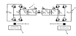
FIG. 1 shows, for example, “Bi-directive inductive powerer”.
It describes a prior art bidirectional IPT system as described in International Publication No. 2010/062198 entitled "transfer", the content of which is incorporated herein by reference.
IPTシステムは、プライマリ1と、ピックアップとも呼ばれるセカンダリ2(1つの
ピックアップのみが図示されている)とを備える。プライマリ1とピックアップ2とは、
エアギャップによって離隔されており、コンバータとインダクタ-キャパシタ-インダク
タ(LCL)共振回路網とコントローラとを備える同等の電子回路を使用する。プライマ
リコントローラ3とセカンダリコントローラ4とは互い独立しており、エアギャップの両
端間で電力潮流を調整するためにそれぞれに備えられたコンバータを動作させる。プライ
マリコントローラは、トラックと呼ばれコイルLTによって表されるプライマリ巻線中に
所望の周波数の一定の正弦波電流を生成するために、LCL共振回路網Lpi、CT、L
Tに接続されたプライマリ側コンバータを動作させる。典型的なIPTシステムでは、動
作周波数は、10~100kHzの範囲となる。トラックインダクタンスLTは、セカン
ダリまたはピックアップのコイルLsiに磁気結合されている。したがって、ピックアッ
プ2のLCL回路は、LsiとCSとLsoとを備える。
The IPT system comprises a primary 1 and a secondary 2 (only one pickup is shown), also referred to as a pickup. Primary 1 and
Separated by an air gap, an equivalent electronic circuit with a converter and an inductor-capacitor-inductor (LCL) resonant network and a controller is used. The primary controller 3 and the secondary controller 4 are independent of each other and operate their respective converters to adjust the power flow between both ends of the air gap. The primary controller, called the track, is the LCL resonant network Lpi , CT , L to generate a constant sinusoidal current of the desired frequency in the primary winding represented by the coil LT.
Operate the primary side converter connected to T. In a typical IPT system, the operating frequency is in the range of 10-100 kHz. The track inductance LT is magnetically coupled to the secondary or pickup coil L si . Therefore, the LCL circuit of the
システムの両側のLCL回路は、通常、プライマリまたはソース側1のコンバータによ
って発生されるトラック電流の周波数に同調される。IPTシステムの各コンバータは、
電力潮流の方向に応じて、反転モードまたは整流モードのいずれかで動作される。電力潮
流の量および方向は、以下で説明するように、相対位相角度および/またはコンバータに
よって生成される電圧の大きさによって制御され得る。
The LCL circuits on either side of the system are typically tuned to the frequency of the track current generated by the primary or
It operates in either inversion mode or rectification mode, depending on the direction of the power flow. The amount and direction of power flow can be controlled by the relative phase angle and / or the magnitude of the voltage generated by the converter, as described below.
プライマリ側コンバータが角周波数ωの基準正弦波電圧Vpi∠0を生成する場合、ト
ラック電流ITは、プライマリ側コントローラ3によって一定に保持される。定常状態で
は、トラック電流ITに起因するピックアップコイルLsi中の誘導電圧Vsiは、式(
1)によって求めることができる。
![]()
式中、Mは、トラックインダクタンスLTとピックアップコイルインダクタンスLsiと
の間の磁気結合を表す。
When the primary side converter produces a reference sinusoidal voltage V pi ∠0 with an angular frequency ω, the track current IT is held constant by the primary side controller 3. In the steady state, the induced voltage V si in the pickup coil L si due to the track current IT is given by the equation (
It can be obtained by 1).
![]()
In the equation, M represents the magnetic coupling between the track inductance LT and the pickup coil inductance L si .
ピックアップは、セカンダリコントローラによって、ソースまたはシンクのいずれかと
して動作させることができる。動作モードにかかわらず、トラックに反映される電圧Vr
は、式(2)によって表すことができる。
![]()
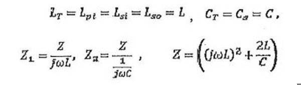
プライマリ側とピックアップ側の両方のLCL回路が角周波数ωに同調され、Lpi=L
T、Lsi=Lsoである場合、
![]()
となる。
The pickup can be operated as either a source or a sink by a secondary controller. The voltage V r reflected on the track regardless of the operating mode
Can be expressed by the equation (2).
![]()
Both the LCL circuits on the primary side and the pickup side are tuned to the angular frequency ω, and L pi = L.
When T , L si = L so ,
![]()
Will be.
通常、DCブロッキングキャパシタCpiは、インダクタLpiおよびプライマリ側コ
ンバータと直列に接続される。同様に、DCブロッキングキャパシタCsoはまた、イン
ダクタLsoおよびピックアップ側コンバータと直列に接続される。この状況では、プラ
イマリコンバータとCTとの間の実効インダクタンスLpi,eと、ピックアップコンバ
ータとCSとの間の実効インダクタンスLso,eとは、
![]()
によって求められる。また、
![]()
という条件を満たす。
Normally, the DC blocking capacitor C pi is connected in series with the inductor L pi and the primary side converter. Similarly, the DC blocking capacitor C so is also connected in series with the inductor L so and the pickup side converter. In this situation, the effective inductance Lpi, e between the primary converter and CT and the effective inductance Lso , e between the pickup converter and CS are
![]()
Is required by. again,
![]()
Satisfy the condition.
これらの条件下では、プライマリ側1の入力電流Ipiおよびトラック電流ITは式(
4)および式(5)によって求められることが分かる。
![]()
![]()
It can be seen that it is obtained by 4) and equation (5).
![]()
![]()
同様に、ピックアップ回路2の入力電流Isiおよび出力電流Isoは、式(6)およ
び式(7)によって求めることができる。
![]()
![]()
![]()
![]()
Isoについては、式(1)~(7)を使用して解く。
![]()
![]()
出力の等価な交流電圧またはピックアップ側2コンバータの入力電圧がVso∠-θに
よって求められる場合、式(9)によってピックアップの電力出力Poが求められる。
![]()
![]()
(9)のVsoとIsoとに代入する。
![]()
![]()
位相角θが±90°のときに電力伝送が最大となることは式(10)から明らかである
。進み位相角は、ピックアップからプライマリへの電力伝送を構成し、遅れ位相角は、プ
ライマリからピックアップに電力伝送をイネーブルする。したがって、任意の所与のプラ
イマリ電圧およびピックアップ電圧については、プライマリコンバータおよびセカンダリ
コンバータによって生成される電圧の大きさと相対位相角の両方を制御することによって
、プライマリとピックアップとの間の電力潮流の量と方向の両方を調整することができる
。
It is clear from Eq. (10) that the power transmission is maximized when the phase angle θ is ± 90 °. The lead phase angle constitutes power transfer from the pickup to the primary, and the lag phase angle enables power transfer from the primary to the pickup. Therefore, for any given primary and pickup voltage, the amount of power flow between the primary and pickup by controlling both the magnitude and relative phase angle of the voltage generated by the primary and secondary converters. And the direction can be adjusted.
IPTシステムの典型的な電力対周波数特性によれば、LCL回路網の同調周波数にお
ける動作は、0無効電力またはVAR循環を保証し、任意の所与の電力レベルについて、
コンバータの必要VA定格を最低限に制限する。同調周波数を下回るまたはそれを上回る
周波数におけるシステムの動作は、常に、コンバータの最大有効電力処理能力においてV
AR循環およびドロップを生じることになる。しかしながら、図2に示したようなIPT
システムの電力対周波数特性は、同調周波数あたりの動作周波数におけるわずかな変化は
、電力処理能力の著しいドロップも、VA定格を超えるための循環エネルギーの増大も生
じない。IPTシステムの電力周波数特性のこの特徴は、以下にさらに詳細に記載するよ
うに、本発明において利用される。
According to the typical power vs. frequency characteristics of an IPT system, operation at the tuning frequency of the LCL network guarantees zero reactive power or VAR circulation, and for any given power level.
Limit the required VA rating of the converter to a minimum. System operation at frequencies below or above the tuning frequency is always V at the converter's maximum active power processing capacity.
AR circulation and drops will occur. However, the IPT as shown in FIG.
The power-to-frequency characteristics of the system show that slight changes in operating frequency per tuning frequency do not result in a significant drop in power processing capacity or an increase in circulating energy to exceed the VA rating. This feature of the power frequency characteristics of the IPT system is utilized in the present invention as described in more detail below.
第1の実施例
図2に示したIPTシステムの電力対周波数ドループ特性は、本発明のドループ制御技
法にしたがって電力潮流を制御するために、周波数がどのように線形に変化し得るかを示
す。この実施例および提供される他の実施例では、必ずしも線形変化するわけではなく、
すなわち、動作周波数の変化は、電流電力伝送と給電能力との差に非線形比例することが
ある。
First Example The power vs. frequency droop characteristic of the IPT system shown in FIG. 2 shows how the frequency can change linearly in order to control the power flow according to the droop control technique of the present invention. In this example and the other examples provided, it does not necessarily change linearly.
That is, the change in operating frequency may be non-linearly proportional to the difference between current power transmission and power feeding capacity.
プライマリ側は、ドループ特性にしたがって動作周波数を規定し、ピックアップコンバ
ータは単純に追従する。どちらの側も、システムが定格電力を送達するまたは受信すると
きにのみ同調周波数foで動作する。他のすべての電力レベルでは、このシステムは、シ
ステムのVA定格に背くことなく、わずかに離調した周波数で動作する。
The primary side defines the operating frequency according to the droop characteristics, and the pickup converter simply follows. Both sides operate at the tuning frequency fo only when the system delivers or receives rated power. At all other power levels, the system operates at slightly detuned frequencies without violating the system's VA rating.
最大動作周波数fmaxおよび最小動作周波数fminは、順方向電力潮流および逆方
向電力潮流中のそれぞれのプライマリおよびピックアップの無荷重動作または0電力伝送
動作にそれぞれ対応する。通常、fmaxおよびfminは、同調周波数数百ヘルツ上回
るまたは下回るように(典型的には10~40kHzの範囲内の具体的な周波数に)設定
される。周波数のこの比較的小さい変化により、プライマリコンバータおよびセカンダリ
コンバータの両方のLCL回路網が実質的に同調されたままであり、しかも、同調周波数
f0と比較して、プライマリ/セカンダリコントローラによって検出されるのに十分な大
きさであることが保証される。1つの実施形態では、周波数は、ピックアップをプライマ
リに同期させるためにも使用される位相ロックループ(PLL)を使用して、検出および
測定される。PLLの出力は、マイクロコントローラの割込みピンに供給される方形波で
ある。マイクロコントローラのタイマーは、割込み同士間の時間を測定し、連続する割込
みを平均化(またはより適切に)することによって、動作周波数が推定され得る。
The maximum operating frequency fmax and the minimum operating frequency fmin correspond to the unloaded operation or the zero power transmission operation of the respective primary and pickup during the forward power flow and the reverse power flow, respectively. Generally, fmax and fmin are set to be above or below the tuning frequency of several hundred hertz (typically to a specific frequency in the range of 10-40 kHz). This relatively small change in frequency keeps the LCL networks of both the primary and secondary converters substantially tuned, even though they are detected by the primary / secondary controller compared to the tuned frequency f0. Guaranteed to be large enough. In one embodiment, the frequency is detected and measured using a phase-locked loop (PLL), which is also used to synchronize the pickup to the primary. The output of the PLL is a square wave supplied to the interrupt pin of the microcontroller. Microcontroller timers can estimate the operating frequency by measuring the time between interrupts and averaging (or more appropriately) consecutive interrupts.
検出され得る最小変化はタイマーの速度に依存し、タイマーが16MHzで動作する場
合には、検出され得る最小変化は50Hzである。これは、より速いマイクロコントロー
ラを用いて改善され得る。
The minimum change that can be detected depends on the speed of the timer, and if the timer operates at 16 MHz, the minimum change that can be detected is 50 Hz. This can be improved with a faster microcontroller.
図3(a)および図3(b)を参照して、例としてドループ制御について記載する。プ
ライマリ(Pmax,pである)の電力定格よりも高い電力定格Pmax,sを有するピ
ックアップが、fmaxで(すなわち、負荷なく)アイドリングしているプライマリコン
バータから電力を抽出し始めるときの状況について考える。この状況は、図3(a)では
点Aによって示される。ピックアップコントローラ4は、点Bによって示すように、プラ
イマリはfmaxでアイドリングしており、電力の抽出開始を検出する。1つの実施形態
では、プライマリコントローラ3は、コントローラ3によって設定されるサンプリングレ
ートのその電力出力を、継続的または周期的に監視する。サンプルからの電力出力は、一
定の時間期間にわたる推定電力出力を求めるために平均化される。サンプリングレートは
、動作周波数およびマイクロコントローラの速度を考慮に入れて、推定出力電力が、周波
数を変化させることによってピックアップ側に搬送すべき実出力電力の良好な指標となる
ように判断される。ピックアップ2が電力を取り始めことを認識すると、プライマリコン
バータは、次のサンプリング時に、動作周波数を点Cによって示されるfcまで低減する
。ピックアップ2は、次に、新しい動作周波数に固定し、周波数が依然としてfoよりも
高いことを認識し、したがって、より多くの電力を抽出し続ける。このプロセスは、動作
周波数がドループ特性上の同調周波数f0または点Dに収束するまで続く。周波数がf0
であることを検出したピックアップ2は、プライマリ1が最大可能電力レベルであり、そ
のパワーインテークをPmax,pに制限することを認識する。
Droop control will be described as an example with reference to FIGS. 3 (a) and 3 (b). Situation when a pickup with a power rating of P max, s higher than the power rating of the primary (P max, p ) begins to extract power from the primary converter idling at f max (ie, without load). think about. This situation is indicated by point A in FIG. 3 (a). As indicated by point B, the pickup controller 4 has the primary idling at f max and detects the start of power extraction. In one embodiment, the primary controller 3 continuously or periodically monitors its power output at the sampling rate set by the controller 3. The power output from the sample is averaged to obtain an estimated power output over a period of time. The sampling rate is determined so that the estimated output power is a good indicator of the actual output power to be carried to the pickup side by varying the frequency, taking into account the operating frequency and the speed of the microcontroller. Recognizing that
The
対照的に、図3(b)は、ピックアップの需要がプライマリの電力定格よりも低い状況
を示す。この状況では、システムは、セカンダリの電力処理能力Pmax,sに対応する
安定した動作周波数fDへと安定し、動作周波数fDは、プライマリの電力処理能力Pm
ax,Pと対応する同調周波数foよりもわずかに大きい。別のピックアップがある場合
、システムはまた、プライマリコントローラによって規定される周波数に応じた電力を取
る。プライマリは(すなわち、両方のピックアップによって取られる)電力出力を推定し
、それに応じて、その動作周波数を変え、その給電能力(または供給され得る残存電力)
を両方のピックアップに示す。このプロシージャは、プライマリがその給電能力に達する
まで続く。
In contrast, FIG. 3 (b) shows a situation where the demand for pickups is lower than the power rating of the primary. In this situation, the system stabilizes to a stable operating frequency f D corresponding to the secondary power processing capacity P max, s , where the operating frequency f D is the primary power processing capacity P m .
It is slightly larger than the tuning frequency fo corresponding to ax and P. If there is another pickup, the system also takes power according to the frequency specified by the primary controller. The primary estimates the power output (ie, taken by both pickups), changes its operating frequency accordingly, and its feeding capacity (or residual power that can be supplied).
Is shown on both pickups. This procedure continues until the primary reaches its power supply capacity.
図2の提案されたドループ特性から、動作周波数fは式(11)によってプライマリ電
力Ppに関係付けられることが分かる。
![]()
式中、df/dpは、必要に応じて変わり得る電力対周波数ドループである。システムの
効率がηであると仮定される場合、ピックアップ電力Psは式(12)によってプライマ
リ電力Ppに関係付けられる。
![]()
![]()
In the equation, df / dp is a power vs. frequency droop that can change as needed. If the efficiency of the system is assumed to be η, the pickup power Ps is related to the primary power Pp by Eq. (12).
![]()
式(11)で式(12)を代入する。
![]()

![]()
式(13)および式(14)を使用して,動作周波数および電力スループットを分析す
ることができ、以下で説明するように、提案されたドループコントローラを実装すること
が必要な関係が与えられる。
Equations (13) and (14) can be used to analyze operating frequencies and power throughput, and the relationships required to implement the proposed droop controller are given, as described below.
式(10)によれば、プライマリ1とピックアップ2との間の電力潮流は、所与のプラ
イマリ電圧について力率1でピックアップ側コンバータによって発生される電圧の制御に
よって調整され得る。1つの実施形態では、プライマリコンバータは、定電圧を発生させ
、トラック電流をすべての負荷について一定に保つように、方形波電圧によって駆動され
る。ピックアップコンバータVsiによって発生された電圧は、必要に応じて、パルス幅
変調によって調整される。図1のHブリッジスイッチコンバータの場合、例えば、ピック
アップ側コンバータは、2つのレッグ(各レッグは2つのスイッチを含んでいる)を有す
る。調整11は、レッグを互いに対して位相シフトαで駆動することによって達成した。
0°または360°の位相シフトは、最大可能電圧の方形波を発生させ、両方の方向の最
大電力潮流(すなわち、100%デューティーサイクル)に対応する。対照的に、180
°の位相シフトは、トラックからピックアップを効果的に結合解除することによって短絡
を生成するので、ゼロ電圧(すなわち0%デューティーサイクル)を発生させる。位相シ
フトは、効果的な出力電圧を、したがって電流を変化させるので、電力出力は、位相シフ
トによって制御され得る。
According to equation (10), the power flow between the primary 1 and the
A phase shift of 0 ° or 360 ° produces a square wave with a maximum possible voltage and corresponds to a maximum power flow (ie, 100% duty cycle) in both directions. In contrast, 180
A phase shift of ° creates a short circuit by effectively uncoupling the pickup from the track, thus producing a zero voltage (
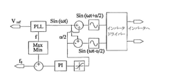
図4に、本発明によるピックアップドループコントローラ4の1つの実施形態のブロッ
ク図を例として示す。ピックアップコントローラ4は、ピックアップコイルLSi電圧V
siを感知し、プライマリコンバータの周波数を判断するために位相ロックループ(PL
L)を使用する。動作周波数と同調周波数f0との間の誤差は、所望の電力を抽出するた
めに必要な位相シフトaを発生させるために、比例積分(PI)コントローラに供給され
る。位相シフトが0°~360°に保たれることを保証するために、PIコントローラの
出力に限界値が配置される。180°では、電力は一切伝送されないが、0°および36
0°は、順方向および逆方向の最大電力にそれぞれ対応する。
FIG. 4 shows a block diagram of one embodiment of the pickup droop controller 4 according to the present invention as an example. The pickup controller 4 is a pickup coil L Si voltage V.
Phase lock loop (PL) to detect si and determine the frequency of the primary converter
L) is used. The error between the operating frequency and the tuning frequency f 0 is supplied to the proportional integral (PI) controller to generate the phase shift a required to extract the desired power. A limit is placed on the output of the PI controller to ensure that the phase shift is kept between 0 ° and 360 °. At 180 ° no power is transmitted, but at 0 ° and 36
0 ° corresponds to the maximum power in the forward and reverse directions, respectively.
式(8)によって求められるピックアップの出力電流は、式(3)によって求められる
ように、完全に同調させた状態で導出された。しかしながら、ドループコントローラは、
ピックアップのパワーインテークを調整するために、動作周波数を変化させる。したがっ
て、定格電力以外では、システムは離調状態で動作する。周波数の変化に起因する有効電
力と無効電力の両方の大きさに対する影響は、離調状態下のシステム変数について式を導
出することによって調べることができる。
The pickup output current determined by equation (8) was derived in a perfectly tuned state as determined by equation (3). However, the droop controller is
Change the operating frequency to adjust the power intake of the pickup. Therefore, except for the rated power, the system operates in a detuned state. The effect of frequency changes on the magnitude of both active and reactive power can be investigated by deriving equations for system variables under detuning conditions.
任意の所与の動作角周波数ωについて、ピックアップの出力電流は、式(15)によっ
て求められる。

ただし、
However,
ピックアップの有効電力出力は式(9)によって求められ、ピックアップの無効電力Q
oは式(16)によって求められる。
![]()
o is obtained by the equation (16).
![]()
システムが同調周波数で動作しているとき、ピックアップの有効電力成分および無効電
力成分は、式(10)および式(17)によって求められる。
![]()
![]()
したがって、周波数の変化に起因するPoおよびQoに対する影響は、式(9)、(1
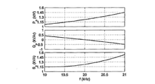
5)および(16)を使用することによって分析することができる。図5は、電力の有効
成分、無効成分および皮相成分が動作周波数とともにどのように変化するかを示している
。電力を計算するために分析式を使用すると、プライマリ側コンバータもピックアップ側
コンバータも、90°の相対位相角で定格電圧を生成するとみなされる。システムは、式
(17)によって求められるように、20kHzの同調周波数において力率1で動作して
いることは、図5から明らかである。システムの周波数が変化されると、システムの無効
電力要件が増大し、したがって、VA定格も増大する。しかしながら、ドループコントロ
ーラによって採用される最高周波数変化が狭帯域内に保たれる場合、無効電力の増加も皮
相電力の増加も比較的少なく、コンバータのVA定格を損なうことはない。
Therefore, the effects on Po and Qo caused by the change in frequency are given in equations (9) and (1).
It can be analyzed by using 5) and (16). FIG. 5 shows how the active, ineffective and apparent components of electric power change with operating frequency. Using the analytical formula to calculate the power, both the primary and pickup side converters are considered to generate rated voltage with a relative phase angle of 90 °. It is clear from FIG. 5 that the system operates at a power factor of 1 at a tuning frequency of 20 kHz, as determined by equation (17). As the frequency of the system changes, the reactive power requirements of the system increase and therefore the VA rating also increases. However, when the maximum frequency change adopted by the droop controller is kept within a narrow band, the increase in reactive power and the increase in apparent power are relatively small and do not impair the VA rating of the converter.
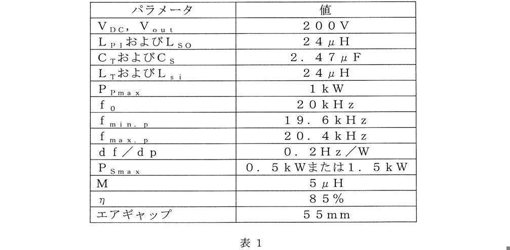
本発明の「ドループ」制御技術のシミュレーションは、1kWのプライマリ双方向コン
バータと1.5kWの双方向ピックアップコンバータとを備えるプロトタイプのIPTシ
ステムを用いて実験的に検証された。プロトタイプのシステムのパラメータを表1に示す
。
カリフォルニア州サンノゼのAtmel Corporationから入手可能な、A
Tmega-324Pモデル8ビットマイクロコントローラを使用して、プライマリおよ
びピックアップ側「ドループ」コントローラを実装した。方形波電圧を生成し、55Aの
一定のトラック電流を維持するように、200V DC電源によって供給され、1kWに
制限されるプライマリ側コンバータを制御した。プライマリコンバータから電力を提供す
るまたは抽出するために、ピックアップをトラックに磁気結合した。ピックアップ側コン
バータを、200V DC電源により動作させ、プライマリに関して90度位相遅れで駆
動させ、それにより、式(10)にしたがって同調したときに、システムが力率1で動作
することが保証された。ピックアップコントローラは、プライマリコンバータによって規
定される周波数でピックアップ側コンバータを動作させ、供給されるまたは抽出される電
力量を制御するために、そのフルブリッジコンバータの2つのレッグ間で位相シフトを変
化させる。
A, available from Atmel Corporation in San Jose, California
A primary and pickup side "droop" controller was implemented using a Tmega-324P model 8-bit microcontroller. A primary side converter powered by a 200V DC power supply and limited to 1kW was controlled to generate a square wave voltage and maintain a constant track current of 55A. The pickup was magnetically coupled to the track to provide or extract power from the primary converter. The pickup-side converter was run on a 200V DC power supply and driven with a 90 degree phase lag with respect to the primary, thereby ensuring that the system would operate at a power factor of 1 when tuned according to equation (10). The pickup controller operates the pickup side converter at a frequency defined by the primary converter and changes the phase shift between the two legs of its full bridge converter to control the amount of power supplied or extracted.
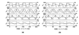
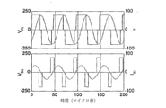
ピックアップの電力定格がプライマリの電力定格よりも低いときのシステムのシミュレ
ートされた定常状態波形を図6(a)に示す。プライマリは、低電力需要を満たすために
、同調周波数からわずかにはずれた周波数で動作する。最上部のプロットおよび3つ目の
プロットから、ピックアップは、プライマリコンバータ電圧Vpiより遅れた方形波電圧
Vsiを生成することが明らかである。したがって、電力は、プライマリからピックアッ
プに流れる。トラック電流ITは、約55A rmsの正弦波であり、一定である。
Figure 6 (a) shows a simulated steady-state waveform of the system when the pickup power rating is lower than the primary power rating. The primary operates at a frequency slightly off the tuning frequency to meet the low power demand. From the top plot and the third plot, it is clear that the pickup produces a square wave voltage V si lagging behind the primary converter voltage V pi . Therefore, power flows from the primary to the pickup. The track current IT is a sine wave of about 55 Arms and is constant.
図6(b)は同じ状態での実験結果を示し、シミュレーション結果と実験結果とは非常
によく似ていることが明らかである。
FIG. 6B shows the experimental results in the same state, and it is clear that the simulation results and the experimental results are very similar.
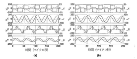
図7は、ピックアップの電力需要が1kWのプライマリ給電能力よりも高いときのシス
テムの(a)シミュレーション波形および(b)実験波形を示す。ピックアップ電力を増
大させるために、位相シフトαを増大させること(すなわち、セカンダリインバータのデ
ューティーサイクルを増加させること)によって、Vsoの大きさを増大させた。Vso
の増大は図7から明らかである。ピックアップ電力が約1kWに達すると、プライマリ周
波数は同調周波数に収束し、ピックアップコントローラの電力を強制的に1kWの最大値
に制限する。出力電力の変化にかかわらず、プライマリコントローラは、一定のトラック
電流ITを維持している。この状況でも、シミュレーション結果と実験結果とは、非常に
良好に合致している。
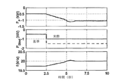
FIG. 7 shows (a) a simulation waveform and (b) an experimental waveform of the system when the power demand of the pickup is higher than the primary power supply capacity of 1 kW. In order to increase the pickup power, the magnitude of V so was increased by increasing the phase shift α (that is, increasing the duty cycle of the secondary inverter). V so
The increase in is clear from FIG. When the pickup power reaches about 1 kW, the primary frequency converges to the tuning frequency, forcing the pickup controller power to limit to a maximum of 1 kW. The primary controller maintains a constant track current IT regardless of changes in output power. Even in this situation, the simulation results and the experimental results are in very good agreement.
図8(a)は、プライマリ電力、ピックアップ電力限界および動作周波数のシミュレー
トした経時変化を示す。最初に、ピックアップコントローラは、0.5kWの最大電力レ
ベルに設定される。したがって、システムは、f0よりも大きい周波数で動作するように
安定し、プライマリ電源がその最大電力レベルで動作していないことが示される。0.2
5秒に、ピックアップ電力基準は、プライマリ電源の給電能力よりも大きい1.5kWに
変更される。ピックアップコントローラは、パワーインテークを徐々に増大させ、プライ
マリコントローラは、パワーインテークがプライマリの最大能力に達していることを示す
ために動作周波数を低減させる。最終的には、動作周波数は、20kHzの同調周波数で
安定し、ピックアップは、1.5kWのより高い基準値であるにもかかわらず、そのパワ
ーインテークを1kWに制限する。図8(b)は、同じ状態での実験結果を示す。プロト
タイプのマイクロコントローラの制限された処理能力によって生じるピックアップコント
ローラのより遅い応答時間は別として、シミュレーション結果および実験結果は、良好に
合致しており、ドループ制御技法の妥当性が確認される。
FIG. 8 (a) shows simulated time course of primary power, pickup power limit and operating frequency. First, the pickup controller is set to a maximum power level of 0.5 kW. Therefore, the system is stable to operate at frequencies above f 0 , indicating that the primary power supply is not operating at its maximum power level. 0.2
In 5 seconds, the pickup power standard is changed to 1.5 kW, which is larger than the power supply capacity of the primary power supply. The pickup controller gradually increases the power intake, and the primary controller reduces the operating frequency to indicate that the power intake has reached the primary's maximum capacity. Ultimately, the operating frequency stabilizes at a tuning frequency of 20 kHz and the pickup limits its power intake to 1 kW, despite the higher reference value of 1.5 kW. FIG. 8B shows the experimental results in the same state. Apart from the slower response times of the pickup controller caused by the limited processing power of the prototype microcontroller, the simulation and experimental results are in good agreement, confirming the validity of the droop control technique.
図9は、逆電力潮流中のプロトタイプのプライマリコンバータおよびセカンダリコンバ
ータの測定電圧波形および電流波形を示す。両方のコンバータの電圧および電流の大きさ
は順方向電力潮流に対応するものと同様であるが、予想通り、プライマリコンバータ電圧
Vpiはピックアップ電圧Vsoより遅れている。電力潮流は、コンバータのデューティ
ーサイクルを制御するためにコンバータのレッグ間の位相シフトαを使用して、ピックア
ップ電圧Vsoの大きさを変化させることによって再度制御される。
FIG. 9 shows the measured voltage waveforms and current waveforms of the prototype primary converter and secondary converter during the reverse power flow. The magnitudes of the voltage and current of both converters are similar to those corresponding to the forward power flow, but as expected, the primary converter voltage V pi lags behind the pickup voltage V so . The power flow is re-controlled by varying the magnitude of the pickup voltage V so using the phase shift α between the legs of the converter to control the duty cycle of the converter.
逆電力潮流中のコントローラの測定された挙動を図10に示す。ピックアップコンバー
タの基準電力レベルは、最初0.5kWに設定され、システムは、同調周波数f0より下
に変動し、0.5kWをプライマリに送達する。負リファレンス(すなわち、同調周波数
を下回る動作周波数)は、(すなわち、プライマリにピックアップからの)逆電力潮流を
示すことを留意されたい。0.25秒には、ピックアップの基準電力レベルは、プライマ
リの能力を超える1.5kWまで上昇する。セカンダリコントローラは、好ましくは複数
のステップで電力を徐々に増大させ、プライマリコントローラは、1kWのその電力限界
に達すると20kHzの同調周波数に向かって収束する動作周波数を増大させることによ
って応答する。その時点で、セカンダリコントローラは、動作周波数が同調周波数f0で
あることを感知し、ピックアップがより多くの電力を供給することが可能であっても、電
力伝送を1kWに制限する。
The measured behavior of the controller during the reverse power flow is shown in FIG. The reference power level of the pickup converter is initially set to 0.5 kW and the system fluctuates below the tuning frequency f 0 to deliver 0.5 kW to the primary. Note that negative references (ie, operating frequencies below the tuning frequency) indicate reverse power flow (ie, from the pickup to the primary). At 0.25 seconds, the reference power level of the pickup rises to 1.5 kW, which exceeds the capacity of the primary. The secondary controller responds by gradually increasing the power, preferably in multiple steps, and the primary controller responds by increasing the operating frequency, which converges towards a tuning frequency of 20 kHz when its power limit of 1 kW is reached. At that point, the secondary controller senses that the operating frequency is the tuning frequency f 0 and limits power transfer to 1 kW even if the pickup is capable of supplying more power.
第2の実施例
本発明の代替実施形態では、プライマリコントローラは、周期的または間欠的にトラッ
ク電流の周波数を変調するように適合され、ほとんどの時間にわたって同調周波数f0で
動作する。したがって、本発明の第1の実施例は、(変化する)動作周波数を継続的に維
持する、または動作周波数を少なくとも反復的に監視するということができるが、この第
2の実施例では、変化する動作周波数と不変の同調周波数f0とが交互に生じる。
Second Example In an alternative embodiment of the invention, the primary controller is adapted to periodically or intermittently modulate the frequency of the track current and operates at a tuning frequency f 0 most of the time. Therefore, the first embodiment of the present invention can be said to continuously maintain the (changing) operating frequency, or to monitor the operating frequency at least iteratively, but in this second embodiment, it is changed. The operating frequency and the invariant tuning frequency f 0 alternately occur.
したがって、プライマリコンバータは、その残りの給電能力に関する情報を、短い持続
時間わたってそのまたは各々のピックアップにリレーすると同時に、システムのVA定格
を最小限に抑えるために残りの時間にわって所望の同調周波数で動作する。そのまたは各
々のピックアップは、それ自体の特性にしたがって、周波数変調によって規定される電力
を抽出する。
Therefore, the primary converter relays information about its remaining power capacity to its or each pickup over a short duration, while at the same time desired tuning over the remaining time to minimize the VA rating of the system. Operates at frequency. The or each pickup extracts the power defined by frequency modulation according to its own characteristics.
上述したように、VA要件を最小限に抑えながら電力出力を最大にするためには、LC
L回路網の同調周波数f0でシステムを動作させることが常に好ましい。わずかに同調周
波数を上回るまたはそれを下回る周波数でのシステムの動作は、必ず、システムが提供す
ることができる最大電力のドロップを生じる。しかしながら、システムは、短い時間期間
にわたって周波数を変更することのみよって、ほとんどの時間にわたって、同調周波数で
動作しており、最小無効電力で最大有効電力を供給している。
As mentioned above, in order to maximize power output while minimizing VA requirements, LC
It is always preferable to operate the system at the tuning frequency f0 of the L network. Operation of the system at frequencies slightly above or below the tuning frequency will always result in the maximum power drop that the system can provide. However, the system operates at the tuned frequency for most of the time, providing maximum active power with minimum reactive power, only by changing the frequency over a short period of time.
したがって、本発明のこの実施形態によれば、プライマリコントローラもピックアップ
コントローラも、変調の瞬間中以外は同調周波数で動作する。動作周波数は、変調中に緩
やかに変化し(すなわち、複数の増分ステップで増大または低減し)、それにより、ピッ
クアップは、プライマリと同期したままでいる(すなわち、同じ周波数を維持する)こと
が可能である。ΔPは、最大電力とプライマリコンバータによって供給されている現在の
電力との差を表す。同調周波数f0は、プライマリが出力する最大電力に対応し、最高周
波数fmaxおよび最大周波数fminは、順方向および逆方向の無負荷電力または最大
利用可能電力にそれぞれ対応する。fmaxおよびfminは、LCL回路網が実質的に
同調されたままとなることを保証するために、通常、第1の実施例に関して上述したよう
に、同調周波数を数百ヘルツ上回るまたは下回るように設定される。
Therefore, according to this embodiment of the present invention, both the primary controller and the pickup controller operate at the tuning frequency except during the moment of modulation. The operating frequency changes slowly during modulation (ie, increases or decreases in multiple increment steps), allowing the pickup to remain in sync with the primary (ie, maintain the same frequency). Is. ΔP represents the difference between the maximum power and the current power supplied by the primary converter. The tuning frequency f 0 corresponds to the maximum power output by the primary, and the maximum frequency f max and the maximum frequency f min correspond to the forward and reverse no-load power or the maximum available power, respectively. f max and f min are usually hundreds of hertz above or below the tuning frequency, as described above for the first embodiment, to ensure that the LCL network remains substantially tuned. Is set to.
プライマリとピックアップとの間の電力潮流は、ピックアップ側コンバータによって生
成される電圧の制御によって調整することができる。好適なコントローラのブロック図を
図12に例として示す。ピックアップコンバータによって生成される電圧Vsoは、必要
に応じて、α(コンバータのレッグを切り替える間の位相シフト)を制御することによっ
て調整され、式(18)によって求められる。
![]()
式中、VoutはDC出力電圧ωT=2πf0であり、θはVpiとVsoとの間の位相
遅れである。
The power flow between the primary and the pickup can be adjusted by controlling the voltage generated by the pickup side converter. A block diagram of a suitable controller is shown in FIG. 12 as an example. The voltage V so generated by the pickup converter is adjusted by controlling α (phase shift while switching the legs of the converter), if necessary, and is obtained by the equation (18).
![]()
In the equation, V out is the DC output voltage ωT = 2πf 0 , and θ is the phase lag between V pi and V so .
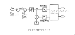
図11に示すプライマリコントローラは、プライマリコンバータから流れる電力である電力(PPin)を測定する。次いで、プライマリが供給することができる最大電力から電力PPinを減算し、プライマリが供給することが可能である残りの利用可能電力PΔを求める。次いで、変化するΔPに、プライマリインバータの周波数を変化させる変調関数を乗算する。周波数変調は、好ましくは1秒間に1度周期的に行われるが、電力潮流が急速に変化しているときには、コントローラは、システムが安定して動作していることを保証するために、より頻繁にジッタ(すなわち、動作周波数の周期的変調)を発生させる。
The primary controller shown in FIG. 11 measures electric power (P Pin ), which is the electric power flowing from the primary converter. Next, the power P Pin is subtracted from the maximum power that can be supplied by the primary to obtain the remaining available power PΔ that can be supplied by the primary. The changing ΔP is then multiplied by a modulation function that changes the frequency of the primary inverter. Frequency modulation is preferably done periodically once per second, but when the power flow is changing rapidly, the controller is more frequent to ensure that the system is operating stably. Jitter (ie, periodic modulation of operating frequency).
本発明のこの実施形態による制御技法の動作について、図1に示したような、3kWピ
ックアップコンバータとともに2.5kWプライマリ双方向コンバータを備える例示的な
IPTシステムを参照しながら以下にさらに詳細に記載する。
The operation of the control technique according to this embodiment of the present invention will be described in more detail below with reference to an exemplary IPT system comprising a 2.5 kW primary bidirectional converter with a 3 kW pickup converter as shown in FIG. ..
プライマリコンバータおよびピックアップコンバータは、方形波電圧VpiおよびVs
oを生成するように制御される。プライマリは、45Aの一定のトラック電流を維持する
ように制御される。この電流は、動作周波数中のジッタが周期的に生じる状態で同調周波
数f0において動作し、その間、残りの利用可能電力は、周波数中のシフトを介してセカ
ンダリ側のそのまたは各々のピックアップに通信される。ピックアップコンバータは、プ
ライマリに対してπ/2ラジアン位相遅れで駆動される。ピックアップコントローラは、
コンバータのレッグ間の位相シフトαを変化させることが可能であり、コンバータのデュ
ーティーサイクルを効果的に変化させることによって、コンバータから抽出または供給さ
れる電力を制御する。
The primary converter and pickup converter are square wave voltages V pi and V s .
It is controlled to generate o . The primary is controlled to maintain a constant track current of 45 A. This current operates at tuning frequency f 0 with periodic jitter in the operating frequency, during which the remaining available power communicates to its or each pickup on the secondary side via a shift in frequency. Will be done. The pickup converter is driven with a π / 2 radian phase lag with respect to the primary. The pickup controller is
It is possible to change the phase shift α between the legs of the converter and control the power extracted or supplied from the converter by effectively changing the duty cycle of the converter.
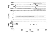
図13は、プライマリからピックアップに電力を供給するシステムの電力と周波数と位
相シフト(α)とを示す。プライマリコントローラの限界は2.5kWに設定され、ピッ
クアップコントローラの限界は、最初、1.5kWに設定される。100ミリ秒後、ピッ
クアップ限界は、プライマリが供給することができる2.5kWよりも大きい3kWまで
増大し、これにより、ピックアップコントローラは、それが取る電力が制限される。周波
数(f)は、ほとんどの時間にわたって、システムが同調周波数(20kHz)で動作す
ることを示す。しかしながら、ジッタ中、周波数はわずかに変化する。図14は、高電力
定常状態ポイントでのコンバータの動作を示す。プライマリコンバータは、100%のデ
ューティーサイクルで動作しているが、セカンダリコンバータのデューティーサイクルは
、負荷によって引き出される電力を2.5kWの最大値に制限するために、実質的により
少ないことが分かる。プライマリトラック電流ITは、45Aの一定の正弦波である。
FIG. 13 shows the power, frequency, and phase shift (α) of a system that supplies power from the primary to the pickup. The limit of the primary controller is set to 2.5 kW and the limit of the pickup controller is initially set to 1.5 kW. After 100 milliseconds, the pickup limit increases to 3 kW, which is greater than the 2.5 kW that the primary can supply, which limits the power taken by the pickup controller. Frequency (f) indicates that the system operates at the tuning frequency (20 kHz) for most of the time. However, the frequency changes slightly during jitter. FIG. 14 shows the operation of the converter at a high power steady state point. It can be seen that the primary converter operates at 100% duty cycle, but the duty cycle of the secondary converter is substantially less because it limits the power drawn by the load to a maximum of 2.5 kW. The primary track current IT is a constant sine wave of 45 A.
以上のことから、様々な態様における本発明は、負荷制御方法、利用可能電力の指標提
供するために周波数を変化させるように適合されたIPT電源、トラック周波数の変化感
知し、それに応じて電力伝送を制限するように適合されたIPTピックアップ、ならびに
/あるいは、利用可能電力をプライマリからそのまたは各々のピックアップに通信するた
めにトラック電流の周波数の変化を使用するIPTシステムで見られることが了解されよ
う。IPTシステムは、単方向でもまたは双方向でもよく、本発明の範囲から逸脱するこ
となく、1以上のIPTピックアップを備え得る。
From the above, the present invention in various aspects is a load control method, an IPT power source adapted to change the frequency to provide an index of available power, sense a change in track frequency, and transmit power accordingly. It will be appreciated that IPT pickups adapted to limit, and / or IPT systems that use changes in the frequency of the track current to communicate available power from the primary to that or each pickup. .. The IPT system may be unidirectional or bidirectional and may include one or more IPT pickups without departing from the scope of the invention.
本発明によるコントローラは、個別電子構成要素または集積回路を含み得る1以上の構
成要素からなるハードウェア中に純粋に実装することができる。それに代えて、またはそ
れに加えて、本発明は、プログラマブル論理デバイス(PLD)またはフィールドプログ
ラマブルゲートアレイ(FPGA)のようなプログラム可能なハードウェア構成要素を使
用して、あるいは、それに応じてプログラムされるマイクロコントローラまたは汎用パー
ソナルコンピュータ(PC)を含み得る計算手段またはプロセッサによって実行されるソ
フトウェアによって実装することができる。しかしながら、典型的には、本発明は、上述
の構成要素の組合せを使用する埋込み型システムとして実装される。
The controller according to the invention can be implemented purely in hardware consisting of one or more components, which may include individual electronic components or integrated circuits. Alternatively or additionally, the invention is programmed using or corresponding to programmable hardware components such as programmable logic devices (PLDs) or field programmable gate arrays (FPGAs). It can be implemented by software executed by a computing means or processor that may include a microcontroller or general purpose personal computer (PC). However, typically, the invention is implemented as an embedded system using the combination of components described above.
したがって、本発明は、専用の通信リンクなしに、必要なときに電力を制限しながら両
方向の電力潮流を調整するために、システムの電力周波数特性を利用するIPT負荷制御
技法を提供する。コントローラは、専用の通信リンクなしに、ロバストかつ低コストで実
装することが比較的容易である。それは、単一または複数のピックアップIPTシステム
に適用可能であり、電力定格を変化させる電気自動車(EV)が単一のプライマリ電源か
ら「効果的」に充電/放電することになるビークルツーグリッド(V2G)システムのよ
うな適用例について理想的である。本制御技法は双方向システムを用いて動作し、したが
って、「セカンダリ」側またはピックアップが「プライマリ」側になり、同じ技法が使用
される。
Accordingly, the present invention provides an IPT load control technique that utilizes the power frequency characteristics of a system to regulate power flow in both directions while limiting power when needed, without a dedicated communication link. The controller is relatively easy to implement robustly and at low cost without a dedicated communication link. It is applicable to a single or multiple pickup IPT system and is a vehicle-to-grid (V2G) where an electric vehicle (EV) with varying power ratings will be "effectively" charged / discharged from a single primary power source. ) Ideal for applications such as systems. This control technique operates with a bidirectional system, so the "secondary" side or pickup is on the "primary" side and the same technique is used.
コンテキストが別段の記載を明らかに要求しない、説明全体にわたって、「備える(「
comprise」、「comprising」)という単語は、排他的または網羅的な
意味ではなく包含的意味で、すなわち、「限定はしないが、含む」という意味で解釈すべ
きである。
Throughout the description, the context clearly does not require a separate statement, "prepare ("
The words "comprise", "comprising") should be interpreted in an inclusive sense, not in an exclusive or exhaustive sense, that is, in the sense of "including, but not limiting".
本発明について、例として、その可能な実施形態に関して説明してきたが、本発明の範
囲から逸脱することなく、修正または改良を行い得ることを理解されたい。本発明は、公
判に、本出願の明細書で参照された、またはそこに示された部品、エレメントまたは特徴
のうちの2つ以上の任意のまたはすべて組合せで、前記部品、エレメントおよび特徴で、
個々にまたは集合的に構成されるということができる。さらに、既知の等価物を有する本
発明の特定の構成要素または完全体について参照された場合、そのような等価物は、あた
かも個々に記載されたかのように本明細書では組み込まれる。
Although the present invention has been described as an example with respect to possible embodiments thereof, it should be understood that modifications or improvements may be made without departing from the scope of the invention. The present invention, in any or all combinations of two or more of the parts, elements or features referred to or set forth herein in the present application, in said parts, elements and features.
It can be said that it is composed individually or collectively. Further, when referenced for a particular component or complete body of the invention having known equivalents, such equivalents are incorporated herein as if they were individually described.
本明細書全体を通じた従来技術に関するあらゆる議論は、決して、そのような先行技術
が広く知られていること、または、当技術分野の通常の一般的な知識の一部を形成するこ
とを承認するものと見なされるべきではない。
Any discussion of prior art throughout this specification will never acknowledge that such prior art is widely known or forms part of the usual general knowledge of the art. Should not be considered a thing.
Claims (20)
前記プライマリ側の電力コンバータが、共振回路及び前記共振誘導電力伝送(IPT)システムのプライマリ導体に電流を供給している間に、送電側であるプライマリ側のコントローラにより、前記プライマリ側の電力コンバータの出力電力を測定するステップと、
前記プライマリ側の電力コンバータの測定した出力電力に応答して、前記送電側であるプライマリ側のコントローラにより、前記プライマリ側の電力コンバータのスイッチング周波数を制御し、前記プライマリ側の電力コンバータが供給することができる残りの利用可能電力を前記プライマリ導体に非接触結合された受電側である1つ以上のピックアップに送電しながら通信するステップと、を有し、
前記残りの利用可能電力は、前記プライマリ側の電力コンバータが供給することができる最大電力から前記測定した出力電力を減算した電力である、方法。 A method of controlling a power converter on the primary side, which is the transmission side of a resonant induction power transfer (IPT) system.
While the power converter on the primary side supplies current to the resonant circuit and the primary conductor of the resonant induced power transfer (IPT) system, the controller on the primary side, which is the transmission side, causes the power converter on the primary side. Steps to measure output power and
In response to the output power measured by the power converter on the primary side, the switching frequency of the power converter on the primary side is controlled by the controller on the primary side, which is the transmission side, and the power converter on the primary side supplies the power. Has a step of communicating while transmitting the remaining available power to one or more pickups that are non-contact coupled to the primary conductor .
The method , wherein the remaining available power is power obtained by subtracting the measured output power from the maximum power that can be supplied by the power converter on the primary side .
受電側である少なくとも1つの誘導電力ピックアップに電力を誘導的に伝送するように構成されたプライマリ導体と、
前記プライマリ導体に電気的に接続された共振回路と、
前記共振回路に電気的に接続され、前記プライマリ導体内の電流を駆動するように構成された電力コンバータと、
前記共振誘導電力伝送(IPT)プライマリの出力電力を測定し、前記共振誘導電力伝送(IPT)プライマリの測定した出力電力に応答して、前記電力コンバータのスイッチング周波数を制御し、前記共振誘導電力伝送(IPT)プライマリが供給することができる残りの利用可能電力を前記プライマリ導体に非接触結合された受電側である1つ以上の誘導電力伝送(IPT)ピックアップに送電しながら通信するように構成されるコントローラと、を含み、
前記残りの利用可能電力は、プライマリ側の前記電力コンバータが供給することができる最大電力から前記測定した出力電力を減算した電力である、共振誘導電力伝送(IPT)プライマリ。 Resonance Inductive Power Transfer (IPT) Primary
A primary conductor configured to inductively transmit power to at least one inductive power pickup on the receiving side.
A resonant circuit electrically connected to the primary conductor,
A power converter electrically connected to the resonant circuit and configured to drive a current in the primary conductor.
The output power of the resonant induced power transmission (IPT) primary is measured, the switching frequency of the power converter is controlled in response to the measured output power of the resonant induced power transmission (IPT) primary, and the resonant induced power transmission is performed. (IPT) configured to communicate while transmitting the remaining available power that can be supplied by the primary to one or more inductive power transfer (IPT) pickups that are non-contact coupled to said primary conductor. Including the controller
The remaining available power is the resonance induced power transfer (IPT) primary, which is the power obtained by subtracting the measured output power from the maximum power that can be supplied by the power converter on the primary side .
誘導電力伝送のために、共振回路および共振誘導電力伝送(IPT)プライマリのプライマリ導体にAC電源を供給するように構成されたブリッジ回路と、
前記電力コンバータの出力電力を測定し、前記電力コンバータの測定した出力電力に応答して、前記ブリッジ回路のスイッチング周波数を制御し、前記電力コンバータが供給することができる残りの利用可能電力を共振誘導電力伝送(IPT)システムの受電側である1つ以上のピックアップに送電しながら通信するように構成されるコントローラと、を含み、
前記残りの利用可能電力は、プライマリ側の前記電力コンバータが供給することができる最大電力から前記測定した出力電力を減算した電力である、電力コンバータ。 It ’s a power converter,
For induced power transmission, a bridge circuit configured to supply AC power to the resonant circuit and the primary conductor of the resonant induced power transmission (IPT) primary,
The output power of the power converter is measured, the switching frequency of the bridge circuit is controlled in response to the measured output power of the power converter, and the remaining available power that can be supplied by the power converter is induced to resonate. Includes a controller configured to communicate while transmitting power to one or more pickups that are the receiving side of a power transmission (IPT) system.
The remaining available power is a power converter obtained by subtracting the measured output power from the maximum power that can be supplied by the power converter on the primary side .
プライマリ導体と、該プライマリ導体に電気的に接続された共振回路と、該共振回路及び前記プライマリ導体内の電流を駆動するように構成された電力コンバータと、プライマリコントローラと、を含む誘導電力伝送(IPT)プライマリと、
該誘導電力伝送(IPT)プライマリに非接触結合し、前記プライマリ導体から電力を誘導的に受けるように構成された少なくとも1つの誘導電力伝送(IPT)ピックアップと、を含み、
前記プライマリコントローラは、前記誘導電力伝送(IPT)プライマリの出力電力を測定し、前記誘導電力伝送(IPT)プライマリの測定した出力電力に応答して、前記電力コンバータのスイッチング周波数を制御し、前記誘導電力伝送(IPT)プライマリが供給することができる残りの利用可能電力を1つ以上の前記誘導電力伝送(IPT)ピックアップに送電しながら通信するように構成され、
前記残りの利用可能電力は、プライマリ側の前記電力コンバータが供給することができる最大電力から前記測定した出力電力を減算した電力である、共振誘導電力伝送(IPT)システム。 Resonance induction power transfer (IPT) system
Induced power transmission including a primary conductor, a resonant circuit electrically connected to the primary conductor, a power converter configured to drive the current in the resonant circuit and the primary conductor, and a primary controller. ( IPT ) Primary and
Includes at least one inductive power transfer (IPT) pickup configured to be non-contact coupled to the inductive power transfer (IPT) primary and configured to inductively receive power from the primary conductor.
The primary controller measures the output power of the inductive power transmission (IPT) primary and controls the switching frequency of the power converter in response to the measured output power of the inductive power transmission (IPT) primary. Inductive power transfer (IPT) is configured to communicate while transmitting the remaining available power that can be supplied by the primary to one or more said inductive power transfer (IPT) pickups .
The remaining available power is a resonant induced power transfer (IPT) system in which the measured output power is subtracted from the maximum power that can be supplied by the power converter on the primary side .
送電側であるプライマリ側の電力コンバータが、共振回路及び前記共振誘導電力伝送(IPT)システムのプライマリ導体に電流を供給している間に、送電側であるプライマリ側のコントローラにより、前記プライマリ側の電力コンバータの出力電力を測定するステップと、
前記プライマリ側の電力コンバータの測定した出力電力に応答して、前記送電側であるプライマリ側のコントローラにより、前記プライマリ側の電力コンバータのスイッチング周波数を制御し、前記プライマリ側の電力コンバータが供給することができる残りの利用可能電力を前記プライマリ導体に非接触結合された受電側である1つ以上のピックアップに送電しながら通信するステップであって、前記残りの利用可能電力は、前記プライマリ側の電力コンバータが供給することができる最大電力から前記測定した出力電力を減算した電力である、ステップと、
前記プライマリ側の電力コンバータの通信された残りの利用可能電力に応答して、前記受電側である1つ以上のピックアップのピックアップコントローラにより、受電側であるセカンダリ側の電力コンバータのスイッチング周波数を制御し、前記1つ以上のピックアップが前記プライマリ側の電力コンバータから引き出した電力を制御するステップと、を有する方法。 A method of controlling a resonant induced power transfer (IPT) system.
While the power converter on the primary side, which is the transmission side, supplies current to the resonant circuit and the primary conductor of the resonant induced power transfer (IPT) system, the controller on the primary side, which is the transmission side, causes the primary side to perform the current. Steps to measure the output power of the power converter,
In response to the output power measured by the power converter on the primary side, the switching frequency of the power converter on the primary side is controlled by the controller on the primary side, which is the transmission side, and the power converter on the primary side supplies the power. The remaining available power is the step of communicating while transmitting the remaining available power to one or more pickups on the receiving side that are non-contact coupled to the primary conductor , wherein the remaining available power is the power on the primary side. The step, which is the power obtained by subtracting the measured output power from the maximum power that can be supplied by the converter .
In response to the remaining available power communicated by the power converter on the primary side, the pickup controller of one or more pickups on the power receiving side controls the switching frequency of the power converter on the secondary side on the power receiving side. A method comprising: controlling the power drawn by the one or more pickups from the power converter on the primary side.
Applications Claiming Priority (2)
| Application Number | Priority Date | Filing Date | Title |
|---|---|---|---|
| NZ593764 | 2011-06-27 | ||
| NZ593764A NZ593764A (en) | 2011-06-27 | 2011-06-27 | Load control for bi-directional inductive power transfer systems |
Related Parent Applications (1)
| Application Number | Title | Priority Date | Filing Date |
|---|---|---|---|
| JP2014518471A Division JP6283309B2 (en) | 2011-06-27 | 2012-06-27 | Load control for bidirectional inductive power transfer system |
Publications (3)
| Publication Number | Publication Date |
|---|---|
| JP2018085925A JP2018085925A (en) | 2018-05-31 |
| JP2018085925A5 JP2018085925A5 (en) | 2018-07-12 |
| JP6991867B2 true JP6991867B2 (en) | 2022-01-13 |
Family
ID=47424360
Family Applications (2)
| Application Number | Title | Priority Date | Filing Date |
|---|---|---|---|
| JP2014518471A Active JP6283309B2 (en) | 2011-06-27 | 2012-06-27 | Load control for bidirectional inductive power transfer system |
| JP2018011056A Active JP6991867B2 (en) | 2011-06-27 | 2018-01-26 | Load control for bidirectional induction power transfer systems |
Family Applications Before (1)
| Application Number | Title | Priority Date | Filing Date |
|---|---|---|---|
| JP2014518471A Active JP6283309B2 (en) | 2011-06-27 | 2012-06-27 | Load control for bidirectional inductive power transfer system |
Country Status (7)
| Country | Link |
|---|---|
| US (2) | US9660702B2 (en) |
| EP (1) | EP2724448B1 (en) |
| JP (2) | JP6283309B2 (en) |
| KR (1) | KR101971203B1 (en) |
| CN (2) | CN107472056B (en) |
| NZ (1) | NZ593764A (en) |
| WO (1) | WO2013002651A1 (en) |
Families Citing this family (42)
| Publication number | Priority date | Publication date | Assignee | Title |
|---|---|---|---|---|
| NZ593764A (en) * | 2011-06-27 | 2013-12-20 | Auckland Uniservices Ltd | Load control for bi-directional inductive power transfer systems |
| US10664772B1 (en) | 2014-03-07 | 2020-05-26 | Steelcase Inc. | Method and system for facilitating collaboration sessions |
| US9716861B1 (en) | 2014-03-07 | 2017-07-25 | Steelcase Inc. | Method and system for facilitating collaboration sessions |
| JP6159894B2 (en) * | 2014-03-25 | 2017-07-05 | コーニンクレッカ フィリップス エヌ ヴェKoninklijke Philips N.V. | Wireless inductive power transfer |
| US9955318B1 (en) | 2014-06-05 | 2018-04-24 | Steelcase Inc. | Space guidance and management system and method |
| US9766079B1 (en) | 2014-10-03 | 2017-09-19 | Steelcase Inc. | Method and system for locating resources and communicating within an enterprise |
| US9380682B2 (en) | 2014-06-05 | 2016-06-28 | Steelcase Inc. | Environment optimization for space based on presence and activities |
| US11744376B2 (en) | 2014-06-06 | 2023-09-05 | Steelcase Inc. | Microclimate control systems and methods |
| US10614694B1 (en) | 2014-06-06 | 2020-04-07 | Steelcase Inc. | Powered furniture assembly |
| US10433646B1 (en) | 2014-06-06 | 2019-10-08 | Steelcaase Inc. | Microclimate control systems and methods |
| US9831684B2 (en) * | 2014-08-08 | 2017-11-28 | Texas Instruments Incorporated | Adaptive rectifier and method of operation |
| EP3180833A4 (en) * | 2014-08-11 | 2018-02-14 | Auckland Uniservices Limited | Resonant frequency compensation |
| US9680312B2 (en) | 2014-09-10 | 2017-06-13 | Qualcomm Incorporated | System and method for reactive power control in dynamic inductive power transfer systems |
| US9852388B1 (en) | 2014-10-03 | 2017-12-26 | Steelcase, Inc. | Method and system for locating resources and communicating within an enterprise |
| CN104539061B (en) * | 2015-01-06 | 2018-11-13 | 宁波微鹅电子科技有限公司 | A kind of electric energy transmitting terminal, wireless electric energy transmission device and wireless power transmission method |
| WO2016134319A1 (en) | 2015-02-19 | 2016-08-25 | Enphase Energy, Inc. | Method and apparatus for time-domain droop control with integrated phasor current control |
| DE102015006277A1 (en) | 2015-05-15 | 2015-12-03 | Daimler Ag | Energy transmission device, cable for this and system of the energy transfer device, the cable and a device to which the means of the power transmission device inductively transmitted electrical current is conductive |
| US10733371B1 (en) | 2015-06-02 | 2020-08-04 | Steelcase Inc. | Template based content preparation system for use with a plurality of space types |
| US10046660B2 (en) | 2015-06-19 | 2018-08-14 | Qualcomm Incorporated | Devices, systems, and methods using reactive power injection for active tuning electric vehicle charging systems |
| CN105141139A (en) * | 2015-08-03 | 2015-12-09 | 重庆大学 | Local communication network (LCL) structure for inductive power transfer (IPT) system and parameter design method of LCL structure |
| CN105186705B (en) * | 2015-08-04 | 2017-11-10 | 宁波微鹅电子科技有限公司 | A kind of efficient electric energy transmitting terminal, non-contact electric energy transmission device and method of electric energy transfer |
| CN105391191A (en) * | 2015-11-17 | 2016-03-09 | 东南大学 | Online power adjusting method applicable to two-way wireless power transmission system |
| US9921726B1 (en) | 2016-06-03 | 2018-03-20 | Steelcase Inc. | Smart workstation method and system |
| WO2018048312A1 (en) | 2016-09-06 | 2018-03-15 | Powerbyproxi Limited | An inductive power transmitter |
| US10651656B2 (en) | 2016-09-14 | 2020-05-12 | Texas Tech University System | UDE-based robust droop control for parallel inverter operation |
| CN106340975B (en) * | 2016-09-30 | 2019-07-02 | 上海空间电源研究所 | A wireless power transmission circuit and design method thereof |
| US10264213B1 (en) | 2016-12-15 | 2019-04-16 | Steelcase Inc. | Content amplification system and method |
| CN107618392B (en) * | 2017-09-29 | 2019-12-31 | 重庆卓谦科技有限公司 | Charging pile self-decision-making electric vehicle charging load random access control system and method |
| US9987937B1 (en) * | 2017-12-20 | 2018-06-05 | The Florida International University Board Of Trustees | Autonomous two-layer predictive controller for bidirectional inductive power transfer in EV applications |
| WO2019147144A1 (en) * | 2018-01-25 | 2019-08-01 | Riar Baljit Singh | A multi-level modular converter |
| EP3784517B1 (en) * | 2018-04-23 | 2023-02-15 | ABB E-mobility B.V. | A power transfer system for electric vehicles and a control method thereof |
| CN109327065B (en) * | 2018-12-06 | 2020-02-21 | 华为技术有限公司 | Receiver, method, power consumption terminal, transmitter and system of wireless charging system |
| KR102155627B1 (en) * | 2018-12-28 | 2020-09-16 | 현대엘리베이터주식회사 | Elevator wireless power control apparatus |
| JP6823112B2 (en) * | 2019-06-10 | 2021-01-27 | 株式会社京三製作所 | Power converter |
| EP4013642A4 (en) * | 2019-08-16 | 2023-09-27 | Auckland UniServices Limited | VEHICLE HOME NETWORK POWER INTERFACE |
| KR102752111B1 (en) | 2019-10-30 | 2025-01-09 | 후아웨이 테크놀러지 컴퍼니 리미티드 | Wireless charging receiver, system and control method |
| CN111355307B (en) * | 2020-03-15 | 2022-09-09 | 东南大学 | A Power Coordinated Control Method for BD-WPT System Based on PI Controller Optimization |
| US12118178B1 (en) | 2020-04-08 | 2024-10-15 | Steelcase Inc. | Wayfinding services method and apparatus |
| US11984739B1 (en) | 2020-07-31 | 2024-05-14 | Steelcase Inc. | Remote power systems, apparatus and methods |
| US12005249B2 (en) * | 2021-02-12 | 2024-06-11 | Medtronic, Inc. | Method for regulating TETS power transfer |
| US12019415B2 (en) | 2022-02-24 | 2024-06-25 | Toyota Motor North America, Inc. | Grouping electric transports for an electric grid |
| DE102022203233A1 (en) * | 2022-04-01 | 2023-10-05 | Robert Bosch Gesellschaft mit beschränkter Haftung | Charging circuit and method for charging a traction battery, electric vehicle |
Citations (10)
| Publication number | Priority date | Publication date | Assignee | Title |
|---|---|---|---|---|
| JP2008206232A (en) | 2007-02-16 | 2008-09-04 | Seiko Epson Corp | Power transmission control device, power reception control device, non-contact power transmission system, power transmission device, power reception device, and electronic equipment |
| JP2009504116A (en) | 2005-07-29 | 2009-01-29 | エルエス ケーブル リミテッド | Non-contact charge battery and charger, battery charge set including these, and charge control method |
| JP2009189231A (en) | 2008-01-09 | 2009-08-20 | Seiko Epson Corp | Power transmission control device, power transmission device, non-contact power transmission system, and electronic device |
| JP2009268181A (en) | 2008-04-22 | 2009-11-12 | Olympus Corp | Energy supply apparatus |
| WO2010006091A1 (en) | 2008-07-09 | 2010-01-14 | Access Business Group International Llc | Wireless charging system |
| JP2010110533A (en) | 2008-11-07 | 2010-05-20 | Olympus Corp | Wireless electric supply system |
| JP2010114965A (en) | 2008-11-04 | 2010-05-20 | Toyota Industries Corp | Non-contact power transmitter and method for designing the non-contact power transmitter |
| JP2010539885A (en) | 2007-09-17 | 2010-12-16 | クゥアルコム・インコーポレイテッド | High efficiency and high power transmission in wireless power magnetic resonator |
| WO2011061821A1 (en) | 2009-11-18 | 2011-05-26 | 株式会社 東芝 | Wireless power transmission device |
| JP2011125184A (en) | 2009-12-14 | 2011-06-23 | Toyota Motor Corp | Contactless power supply facility, contactless power receiving device, and contactless power supply system |
Family Cites Families (31)
| Publication number | Priority date | Publication date | Assignee | Title |
|---|---|---|---|---|
| NO913368D0 (en) * | 1991-08-27 | 1991-08-27 | Julius Hartai | FREQUENCY MODULATED DRIVER WITH PARALLEL RESONANCE. |
| EP0640254B1 (en) * | 1992-05-10 | 2001-08-01 | Auckland Uniservices Limited | A non-contact power distribution system |
| DE4442677A1 (en) * | 1994-11-30 | 1996-06-05 | Siemens Ag | Electricity user power supply method |
| JPH08265986A (en) * | 1995-03-20 | 1996-10-11 | Sumitomo Electric Ind Ltd | Inductive charging method |
| WO1998050993A1 (en) * | 1997-05-06 | 1998-11-12 | Auckland Uniservices Limited | Inductive power transfer across an extended gap |
| US7212414B2 (en) * | 1999-06-21 | 2007-05-01 | Access Business Group International, Llc | Adaptive inductive power supply |
| JP4614961B2 (en) * | 2003-05-23 | 2011-01-19 | オークランド ユニサービシズ リミテッド | Method and apparatus for controlling an inductively coupled power transfer system |
| NZ528542A (en) * | 2003-09-29 | 2006-09-29 | Auckland Uniservices Ltd | Inductively-powered power transfer system with one or more, independently controlled loads |
| CN101292415B (en) * | 2005-10-09 | 2010-12-29 | 崇贸科技股份有限公司 | Apparatus and method for measuring output current from primary side of power converter |
| JP4209437B2 (en) * | 2006-11-10 | 2009-01-14 | 三菱重工業株式会社 | Non-contact power feeding device for mobile body and protection device therefor |
| TWI339471B (en) * | 2006-12-27 | 2011-03-21 | Ind Tech Res Inst | Non-contact power supply having built-in coupling detection device and coupling detection method thereof |
| JP4308858B2 (en) * | 2007-02-16 | 2009-08-05 | セイコーエプソン株式会社 | Power transmission control device, power reception control device, non-contact power transmission system, power transmission device, power reception device, and electronic equipment |
| KR20100130215A (en) * | 2008-03-17 | 2010-12-10 | 파우워매트 엘티디. | Inductive transmission system |
| ES2326780B2 (en) | 2008-05-29 | 2010-06-16 | Fundacion Circe - Centro De Investigacion De Recursos Y Consumos Energeticos | AUTOMATIC METHOD OF CONTROL OF A POWER TRANSFER SYSTEM WITH HIGH FREQUENCY INDUCTIVE COUPLING. |
| US7903435B2 (en) * | 2008-08-05 | 2011-03-08 | System General Corp. | Switching controller having switching frequency hopping for power converter |
| EP4342723A1 (en) * | 2008-08-18 | 2024-03-27 | Christopher B. Austin | Vehicular battery charger, charging system, and method |
| US8299652B2 (en) * | 2008-08-20 | 2012-10-30 | Intel Corporation | Wireless power transfer apparatus and method thereof |
| JP5316541B2 (en) * | 2008-09-26 | 2013-10-16 | 株式会社村田製作所 | Contactless charging system |
| US8692410B2 (en) * | 2008-09-27 | 2014-04-08 | Witricity Corporation | Wireless energy transfer with frequency hopping |
| WO2010062201A1 (en) * | 2008-11-26 | 2010-06-03 | Auckland Uniservices Limited | Primary-side power control for inductive power transfer |
| JP2010198875A (en) * | 2009-02-24 | 2010-09-09 | Panasonic Electric Works Co Ltd | Discharge lamp lighting device and illumination fixture |
| CN201365144Y (en) | 2009-03-02 | 2009-12-16 | 李植扬 | Inductive power supplying device |
| WO2010104569A1 (en) * | 2009-03-09 | 2010-09-16 | Neurds Inc. | System and method for wireless power transfer in implantable medical devices |
| EP2476182B1 (en) * | 2009-09-09 | 2025-01-22 | Auckland UniServices Limited | Power demand management in inductive power transfer systems |
| JP5174769B2 (en) * | 2009-09-11 | 2013-04-03 | 三菱電機株式会社 | Non-contact transmission device |
| JP5664018B2 (en) * | 2009-10-30 | 2015-02-04 | Tdk株式会社 | Wireless power feeder, wireless power transmission system, and table and table lamp using the same |
| KR101730824B1 (en) * | 2009-11-30 | 2017-04-27 | 삼성전자주식회사 | Wireless Power Transceiver and Wireless Power System |
| US8143746B2 (en) * | 2009-12-21 | 2012-03-27 | Alcatel Lucent | Automatic tuning for wireless power transfer |
| CN201733141U (en) | 2010-06-10 | 2011-02-02 | 罗秀玲 | Electronic device |
| US8829726B2 (en) * | 2010-07-02 | 2014-09-09 | Tdk Corporation | Wireless power feeder and wireless power transmission system |
| NZ593764A (en) * | 2011-06-27 | 2013-12-20 | Auckland Uniservices Ltd | Load control for bi-directional inductive power transfer systems |
-
2011
- 2011-06-27 NZ NZ593764A patent/NZ593764A/en not_active Application Discontinuation
-
2012
- 2012-06-27 CN CN201710591343.3A patent/CN107472056B/en active Active
- 2012-06-27 KR KR1020147001559A patent/KR101971203B1/en active Active
- 2012-06-27 EP EP12804818.8A patent/EP2724448B1/en active Active
- 2012-06-27 US US14/127,882 patent/US9660702B2/en active Active
- 2012-06-27 JP JP2014518471A patent/JP6283309B2/en active Active
- 2012-06-27 CN CN201280030503.2A patent/CN103814503B/en active Active
- 2012-06-27 WO PCT/NZ2012/000107 patent/WO2013002651A1/en not_active Ceased
-
2017
- 2017-04-13 US US15/487,267 patent/US10243409B2/en active Active
-
2018
- 2018-01-26 JP JP2018011056A patent/JP6991867B2/en active Active
Patent Citations (10)
| Publication number | Priority date | Publication date | Assignee | Title |
|---|---|---|---|---|
| JP2009504116A (en) | 2005-07-29 | 2009-01-29 | エルエス ケーブル リミテッド | Non-contact charge battery and charger, battery charge set including these, and charge control method |
| JP2008206232A (en) | 2007-02-16 | 2008-09-04 | Seiko Epson Corp | Power transmission control device, power reception control device, non-contact power transmission system, power transmission device, power reception device, and electronic equipment |
| JP2010539885A (en) | 2007-09-17 | 2010-12-16 | クゥアルコム・インコーポレイテッド | High efficiency and high power transmission in wireless power magnetic resonator |
| JP2009189231A (en) | 2008-01-09 | 2009-08-20 | Seiko Epson Corp | Power transmission control device, power transmission device, non-contact power transmission system, and electronic device |
| JP2009268181A (en) | 2008-04-22 | 2009-11-12 | Olympus Corp | Energy supply apparatus |
| WO2010006091A1 (en) | 2008-07-09 | 2010-01-14 | Access Business Group International Llc | Wireless charging system |
| JP2010114965A (en) | 2008-11-04 | 2010-05-20 | Toyota Industries Corp | Non-contact power transmitter and method for designing the non-contact power transmitter |
| JP2010110533A (en) | 2008-11-07 | 2010-05-20 | Olympus Corp | Wireless electric supply system |
| WO2011061821A1 (en) | 2009-11-18 | 2011-05-26 | 株式会社 東芝 | Wireless power transmission device |
| JP2011125184A (en) | 2009-12-14 | 2011-06-23 | Toyota Motor Corp | Contactless power supply facility, contactless power receiving device, and contactless power supply system |
Also Published As
| Publication number | Publication date |
|---|---|
| WO2013002651A1 (en) | 2013-01-03 |
| EP2724448A4 (en) | 2015-05-06 |
| CN107472056A (en) | 2017-12-15 |
| KR20140103248A (en) | 2014-08-26 |
| EP2724448B1 (en) | 2019-02-27 |
| JP6283309B2 (en) | 2018-02-21 |
| US20140203659A1 (en) | 2014-07-24 |
| NZ593764A (en) | 2013-12-20 |
| JP2018085925A (en) | 2018-05-31 |
| KR101971203B1 (en) | 2019-04-22 |
| CN103814503A (en) | 2014-05-21 |
| CN103814503B (en) | 2017-07-28 |
| US10243409B2 (en) | 2019-03-26 |
| US20170229918A1 (en) | 2017-08-10 |
| JP2014521288A (en) | 2014-08-25 |
| US9660702B2 (en) | 2017-05-23 |
| EP2724448A1 (en) | 2014-04-30 |
| CN107472056B (en) | 2020-08-21 |
Similar Documents
| Publication | Publication Date | Title |
|---|---|---|
| JP6991867B2 (en) | Load control for bidirectional induction power transfer systems | |
| Wu et al. | A series-tuned inductive-power-transfer pickup with a controllable AC-voltage output | |
| US8923015B2 (en) | Primary-side power control for inductive power transfer | |
| US10404101B2 (en) | Contactless electric power transmission device and electric power transfer system | |
| EP3343732B1 (en) | Wireless power transmission system and driving method therefor | |
| RU2011116061A (en) | POWER SUPPLY SYSTEM AND ELECTRIC VEHICLE VEHICLE | |
| CN107148712A (en) | Resonant frequency is compensated | |
| WO2010062201A1 (en) | Primary-side power control for inductive power transfer | |
| US10298063B2 (en) | Power-supplying device and wireless power supply system | |
| US11936203B2 (en) | Method for operating a device for wireless transfer of energy in the direction of an electrical consumer by means of inductive coupling and device | |
| JP6675109B2 (en) | Wireless power transmission system | |
| WO2014173033A1 (en) | Receiving end and system and receiving method for wireless power transmission | |
| JP2017060328A (en) | Non-contact power reception device and power transmission system | |
| CN104682570B (en) | Contactless Power Transmission Circuit | |
| JP6714908B1 (en) | Contactless power supply system | |
| US12368375B2 (en) | Wireless power transfer | |
| US20120230058A1 (en) | Non-contact power transmission apparatus | |
| KR102152670B1 (en) | Wireless Power Transfer System and Operating method thereof | |
| WO2021144255A1 (en) | Capacitive power transfer system and method for controlling capacitive power transfer system |
Legal Events
| Date | Code | Title | Description |
|---|---|---|---|
| A521 | Request for written amendment filed |
Free format text: JAPANESE INTERMEDIATE CODE: A523 Effective date: 20180226 |
|
| A621 | Written request for application examination |
Free format text: JAPANESE INTERMEDIATE CODE: A621 Effective date: 20180226 |
|
| A521 | Request for written amendment filed |
Free format text: JAPANESE INTERMEDIATE CODE: A523 Effective date: 20180515 |
|
| A131 | Notification of reasons for refusal |
Free format text: JAPANESE INTERMEDIATE CODE: A131 Effective date: 20190507 |
|
| A601 | Written request for extension of time |
Free format text: JAPANESE INTERMEDIATE CODE: A601 Effective date: 20190806 |
|
| A601 | Written request for extension of time |
Free format text: JAPANESE INTERMEDIATE CODE: A601 Effective date: 20191007 |
|
| A521 | Request for written amendment filed |
Free format text: JAPANESE INTERMEDIATE CODE: A523 Effective date: 20191107 |
|
| A02 | Decision of refusal |
Free format text: JAPANESE INTERMEDIATE CODE: A02 Effective date: 20200512 |
|
| A521 | Request for written amendment filed |
Free format text: JAPANESE INTERMEDIATE CODE: A523 Effective date: 20200911 |
|
| C60 | Trial request (containing other claim documents, opposition documents) |
Free format text: JAPANESE INTERMEDIATE CODE: C60 Effective date: 20200911 |
|
| C11 | Written invitation by the commissioner to file amendments |
Free format text: JAPANESE INTERMEDIATE CODE: C11 Effective date: 20200929 |
|
| A911 | Transfer to examiner for re-examination before appeal (zenchi) |
Free format text: JAPANESE INTERMEDIATE CODE: A911 Effective date: 20201030 |
|
| C21 | Notice of transfer of a case for reconsideration by examiners before appeal proceedings |
Free format text: JAPANESE INTERMEDIATE CODE: C21 Effective date: 20201110 |
|
| A131 | Notification of reasons for refusal |
Free format text: JAPANESE INTERMEDIATE CODE: A131 Effective date: 20201215 |
|
| A601 | Written request for extension of time |
Free format text: JAPANESE INTERMEDIATE CODE: A601 Effective date: 20210312 |
|
| A601 | Written request for extension of time |
Free format text: JAPANESE INTERMEDIATE CODE: A601 Effective date: 20210415 |
|
| A601 | Written request for extension of time |
Free format text: JAPANESE INTERMEDIATE CODE: A601 Effective date: 20210513 |
|
| A521 | Request for written amendment filed |
Free format text: JAPANESE INTERMEDIATE CODE: A523 Effective date: 20210517 |
|
| A912 | Re-examination (zenchi) completed and case transferred to appeal board |
Free format text: JAPANESE INTERMEDIATE CODE: A912 Effective date: 20210730 |
|
| C211 | Notice of termination of reconsideration by examiners before appeal proceedings |
Free format text: JAPANESE INTERMEDIATE CODE: C211 Effective date: 20210803 |
|
| C22 | Notice of designation (change) of administrative judge |
Free format text: JAPANESE INTERMEDIATE CODE: C22 Effective date: 20210824 |
|
| C23 | Notice of termination of proceedings |
Free format text: JAPANESE INTERMEDIATE CODE: C23 Effective date: 20211019 |
|
| C03 | Trial/appeal decision taken |
Free format text: JAPANESE INTERMEDIATE CODE: C03 Effective date: 20211130 |
|
| C30A | Notification sent |
Free format text: JAPANESE INTERMEDIATE CODE: C3012 Effective date: 20211130 |
|
| A61 | First payment of annual fees (during grant procedure) |
Free format text: JAPANESE INTERMEDIATE CODE: A61 Effective date: 20211208 |
|
| R150 | Certificate of patent or registration of utility model |
Ref document number: 6991867 Country of ref document: JP Free format text: JAPANESE INTERMEDIATE CODE: R150 |
|
| R250 | Receipt of annual fees |
Free format text: JAPANESE INTERMEDIATE CODE: R250 |