JP6991828B2 - Seat feeder - Google Patents
Seat feeder Download PDFInfo
- Publication number
- JP6991828B2 JP6991828B2 JP2017203969A JP2017203969A JP6991828B2 JP 6991828 B2 JP6991828 B2 JP 6991828B2 JP 2017203969 A JP2017203969 A JP 2017203969A JP 2017203969 A JP2017203969 A JP 2017203969A JP 6991828 B2 JP6991828 B2 JP 6991828B2
- Authority
- JP
- Japan
- Prior art keywords
- sheet
- feeding
- separating
- rotating body
- seat
- Prior art date
- Legal status (The legal status is an assumption and is not a legal conclusion. Google has not performed a legal analysis and makes no representation as to the accuracy of the status listed.)
- Expired - Fee Related
Links
Images


Classifications
-
- B—PERFORMING OPERATIONS; TRANSPORTING
- B65—CONVEYING; PACKING; STORING; HANDLING THIN OR FILAMENTARY MATERIAL
- B65H—HANDLING THIN OR FILAMENTARY MATERIAL, e.g. SHEETS, WEBS, CABLES
- B65H3/00—Separating articles from piles
- B65H3/46—Supplementary devices or measures to assist separation or prevent double feed
- B65H3/52—Friction retainers acting on under or rear side of article being separated
- B65H3/5207—Non-driven retainers, e.g. movable retainers being moved by the motion of the article
- B65H3/5215—Non-driven retainers, e.g. movable retainers being moved by the motion of the article the retainers positioned under articles separated from the top of the pile
- B65H3/5223—Retainers of the pad-type, e.g. friction pads
-
- B—PERFORMING OPERATIONS; TRANSPORTING
- B65—CONVEYING; PACKING; STORING; HANDLING THIN OR FILAMENTARY MATERIAL
- B65H—HANDLING THIN OR FILAMENTARY MATERIAL, e.g. SHEETS, WEBS, CABLES
- B65H1/00—Supports or magazines for piles from which articles are to be separated
- B65H1/08—Supports or magazines for piles from which articles are to be separated with means for advancing the articles to present the articles to the separating device
- B65H1/14—Supports or magazines for piles from which articles are to be separated with means for advancing the articles to present the articles to the separating device comprising positively-acting mechanical devices
-
- B—PERFORMING OPERATIONS; TRANSPORTING
- B65—CONVEYING; PACKING; STORING; HANDLING THIN OR FILAMENTARY MATERIAL
- B65H—HANDLING THIN OR FILAMENTARY MATERIAL, e.g. SHEETS, WEBS, CABLES
- B65H3/00—Separating articles from piles
- B65H3/02—Separating articles from piles using friction forces between articles and separator
- B65H3/06—Rollers or like rotary separators
- B65H3/0661—Rollers or like rotary separators for separating inclined-stacked articles with separator rollers above the stack
-
- B—PERFORMING OPERATIONS; TRANSPORTING
- B65—CONVEYING; PACKING; STORING; HANDLING THIN OR FILAMENTARY MATERIAL
- B65H—HANDLING THIN OR FILAMENTARY MATERIAL, e.g. SHEETS, WEBS, CABLES
- B65H3/00—Separating articles from piles
- B65H3/02—Separating articles from piles using friction forces between articles and separator
- B65H3/06—Rollers or like rotary separators
- B65H3/0676—Rollers or like rotary separators with two or more separator rollers in the feeding direction
-
- B—PERFORMING OPERATIONS; TRANSPORTING
- B65—CONVEYING; PACKING; STORING; HANDLING THIN OR FILAMENTARY MATERIAL
- B65H—HANDLING THIN OR FILAMENTARY MATERIAL, e.g. SHEETS, WEBS, CABLES
- B65H3/00—Separating articles from piles
- B65H3/46—Supplementary devices or measures to assist separation or prevent double feed
- B65H3/52—Friction retainers acting on under or rear side of article being separated
- B65H3/5246—Driven retainers, i.e. the motion thereof being provided by a dedicated drive
- B65H3/5276—Driven retainers, i.e. the motion thereof being provided by a dedicated drive the retainers positioned over articles separated from the bottom of the pile
- B65H3/5284—Retainers of the roller type, e.g. rollers
-
- B—PERFORMING OPERATIONS; TRANSPORTING
- B65—CONVEYING; PACKING; STORING; HANDLING THIN OR FILAMENTARY MATERIAL
- B65H—HANDLING THIN OR FILAMENTARY MATERIAL, e.g. SHEETS, WEBS, CABLES
- B65H3/00—Separating articles from piles
- B65H3/46—Supplementary devices or measures to assist separation or prevent double feed
- B65H3/56—Elements, e.g. scrapers, fingers, needles, brushes, acting on separated article or on edge of the pile
-
- B—PERFORMING OPERATIONS; TRANSPORTING
- B65—CONVEYING; PACKING; STORING; HANDLING THIN OR FILAMENTARY MATERIAL
- B65H—HANDLING THIN OR FILAMENTARY MATERIAL, e.g. SHEETS, WEBS, CABLES
- B65H2404/00—Parts for transporting or guiding the handled material
- B65H2404/10—Rollers
- B65H2404/14—Roller pairs
- B65H2404/144—Roller pairs with relative movement of the rollers to / from each other
- B65H2404/1441—Roller pairs with relative movement of the rollers to / from each other involving controlled actuator
-
- B—PERFORMING OPERATIONS; TRANSPORTING
- B65—CONVEYING; PACKING; STORING; HANDLING THIN OR FILAMENTARY MATERIAL
- B65H—HANDLING THIN OR FILAMENTARY MATERIAL, e.g. SHEETS, WEBS, CABLES
- B65H2405/00—Parts for holding the handled material
- B65H2405/10—Cassettes, holders, bins, decks, trays, supports or magazines for sheets stacked substantially horizontally
- B65H2405/11—Parts and details thereof
- B65H2405/113—Front, i.e. portion adjacent to the feeding / delivering side
- B65H2405/1136—Front, i.e. portion adjacent to the feeding / delivering side inclined, i.e. forming an angle different from 90 with the bottom
-
- B—PERFORMING OPERATIONS; TRANSPORTING
- B65—CONVEYING; PACKING; STORING; HANDLING THIN OR FILAMENTARY MATERIAL
- B65H—HANDLING THIN OR FILAMENTARY MATERIAL, e.g. SHEETS, WEBS, CABLES
- B65H2511/00—Dimensions; Position; Numbers; Identification; Occurrences
- B65H2511/10—Size; Dimensions
- B65H2511/13—Thickness
-
- B—PERFORMING OPERATIONS; TRANSPORTING
- B65—CONVEYING; PACKING; STORING; HANDLING THIN OR FILAMENTARY MATERIAL
- B65H—HANDLING THIN OR FILAMENTARY MATERIAL, e.g. SHEETS, WEBS, CABLES
- B65H2511/00—Dimensions; Position; Numbers; Identification; Occurrences
- B65H2511/40—Identification
- B65H2511/414—Identification of mode of operation
-
- B—PERFORMING OPERATIONS; TRANSPORTING
- B65—CONVEYING; PACKING; STORING; HANDLING THIN OR FILAMENTARY MATERIAL
- B65H—HANDLING THIN OR FILAMENTARY MATERIAL, e.g. SHEETS, WEBS, CABLES
- B65H2511/00—Dimensions; Position; Numbers; Identification; Occurrences
- B65H2511/40—Identification
- B65H2511/415—Identification of job
-
- B—PERFORMING OPERATIONS; TRANSPORTING
- B65—CONVEYING; PACKING; STORING; HANDLING THIN OR FILAMENTARY MATERIAL
- B65H—HANDLING THIN OR FILAMENTARY MATERIAL, e.g. SHEETS, WEBS, CABLES
- B65H2511/00—Dimensions; Position; Numbers; Identification; Occurrences
- B65H2511/40—Identification
- B65H2511/416—Identification of material
-
- B—PERFORMING OPERATIONS; TRANSPORTING
- B65—CONVEYING; PACKING; STORING; HANDLING THIN OR FILAMENTARY MATERIAL
- B65H—HANDLING THIN OR FILAMENTARY MATERIAL, e.g. SHEETS, WEBS, CABLES
- B65H2515/00—Physical entities not provided for in groups B65H2511/00 or B65H2513/00
- B65H2515/30—Forces; Stresses
-
- B—PERFORMING OPERATIONS; TRANSPORTING
- B65—CONVEYING; PACKING; STORING; HANDLING THIN OR FILAMENTARY MATERIAL
- B65H—HANDLING THIN OR FILAMENTARY MATERIAL, e.g. SHEETS, WEBS, CABLES
- B65H2701/00—Handled material; Storage means
- B65H2701/10—Handled articles or webs
- B65H2701/19—Specific article or web
- B65H2701/1916—Envelopes and articles of mail
-
- B—PERFORMING OPERATIONS; TRANSPORTING
- B65—CONVEYING; PACKING; STORING; HANDLING THIN OR FILAMENTARY MATERIAL
- B65H—HANDLING THIN OR FILAMENTARY MATERIAL, e.g. SHEETS, WEBS, CABLES
- B65H7/00—Controlling article feeding, separating, pile-advancing, or associated apparatus, to take account of incorrect feeding, absence of articles, or presence of faulty articles
- B65H7/02—Controlling article feeding, separating, pile-advancing, or associated apparatus, to take account of incorrect feeding, absence of articles, or presence of faulty articles by feelers or detectors
-
- B—PERFORMING OPERATIONS; TRANSPORTING
- B65—CONVEYING; PACKING; STORING; HANDLING THIN OR FILAMENTARY MATERIAL
- B65H—HANDLING THIN OR FILAMENTARY MATERIAL, e.g. SHEETS, WEBS, CABLES
- B65H7/00—Controlling article feeding, separating, pile-advancing, or associated apparatus, to take account of incorrect feeding, absence of articles, or presence of faulty articles
- B65H7/18—Modifying or stopping actuation of separators
Landscapes
- Engineering & Computer Science (AREA)
- Mechanical Engineering (AREA)
- Sheets, Magazines, And Separation Thereof (AREA)
- Paper Feeding For Electrophotography (AREA)
- Delivering By Means Of Belts And Rollers (AREA)
Description
本発明は、シートを給送するシート給送装置に関する。 The present invention relates to a sheet feeding device that feeds sheets.
プリンタ、複写機、及び複合機等の画像形成装置に用いられるシート給送装置には、フィードローラ等の給送回転体と、給送回転体に当接し、摩擦力によってシートを分離する分離部材とを有する構成が広く用いられている。シートは、例えば給送回転体の上流に配置されるピックアップローラによって搬送されることで、給送回転体と分離部材との間の分離部に突入し、分離部材によって他のシートから分離された状態で1枚ずつ給送される。このような構成のシート給送装置において、分離部に対するシートの進入角度によっては、シートが分離部を通過できずに詰まってしまう場合があることが知られていた。 Sheet feeding devices used in image forming devices such as printers, copiers, and multifunction devices include feeding rotating bodies such as feed rollers and separating members that come into contact with the feeding rotating body and separate the sheets by frictional force. The configuration having and is widely used. The sheet was conveyed, for example, by a pickup roller arranged upstream of the feeding rotating body, so as to enter the separation portion between the feeding rotating body and the separating member, and was separated from the other sheets by the separating member. It will be sent one by one in the state. It has been known that in a sheet feeding device having such a configuration, the sheet may not pass through the separation portion and may be clogged depending on the angle of entry of the sheet with respect to the separation portion.
特許文献1には、切手やカード等の紙葉商品を収容した封筒が載置される載置台と、フィードローラ及びゲートローラからなるローラ対とを備え、ゲートローラによって封筒を分離しながら封筒を給送する装置が記載されている。この装置では、載置台に載置された封筒の姿勢が、ローラ対のニップ部における封筒の搬送方向と水平になるように載置台の姿勢を変更可能であり、これによりニップ部における封筒の詰まり防止を図っている。
しかしながら、封筒や薬袋等のシートや、カールした状態のシート等、厚さ方向のふくらみを有するシートを給送する場合、特許文献1に記載されたシートの載置台の姿勢を変更する手法では、シート詰まりの発生を防げない場合があった。即ち、シートのふくらみにより、シートの先端部がゲートローラに向かって傾斜した状態でニップ部に進入しようとすることで、シートがニップ部の上流でゲートローラに引っ掛かってしまい、ニップ部を通過できないことがあった。一方、封筒がニップ部を通過しやすいように、ゲートローラによるシートの分離能力を単純に低下させるだけでは、普通紙等の平坦なシートを搬送する場合にシートの重送が生じる虞がある。
However, when feeding a sheet having a bulge in the thickness direction, such as a sheet such as an envelope or a medicine bag or a sheet in a curled state, the method of changing the posture of the sheet mounting table described in
そこで、本発明は、シートの分離性能を確保しつつ、シートが詰まる可能性を低減可能なシート給送装置を提供することを目的とする。 Therefore, an object of the present invention is to provide a sheet feeding device capable of reducing the possibility of sheet clogging while ensuring the sheet separation performance.
本発明の一態様に係るシート給送装置は、シートが積載されるシート積載部と、シートに当接して回転する給送回転体を有し、前記シート積載部に積載されたシートをシート給送方向に給送する給送ユニットと、前記給送回転体に当接し、前記給送回転体によって給送されるシートを分離する分離部を前記給送回転体との間に形成する分離部材と、前記給送回転体と前記分離部材とを離間させる離間手段と、前記シート積載部に積載されたシートの上面を押圧可能な押圧部と、前記押圧部が前記シート積載部に積載されたシートの上面を押圧した場合の、当該シートの上下方向における変位を検知可能な検知手段と、前記離間手段により前記給送回転体と前記分離部材とを離間させた状態で、前記シート給送方向におけるシートの下流端が前記分離部の位置を通過するようにシートを給送する第1の給送モードと、前記給送回転体と前記分離部材とを当接させた状態で、シートの前記下流端が前記分離部を通過するようにシートを給送する第2の給送モードと、を含む複数のモードを実行可能な制御手段と、を備え、前記制御手段は、前記検知手段の検知結果に基づいて、前記複数のモードの中のいずれかのモードを実行し前記シート積載部に積載されたシートを給送させる、ことを特徴とする。 The sheet feeding device according to one aspect of the present invention has a seat loading section on which a sheet is loaded and a feeding rotating body that rotates in contact with the sheet, and feeds the sheet loaded on the sheet loading section. Separation that forms a separation part between the feeding unit that feeds in the feeding direction and the feeding rotating body that abuts on the feeding rotating body and separates the sheet that is fed by the feeding rotating body. A separating means for separating the member, the feeding rotating body and the separating member, a pressing portion capable of pressing the upper surface of the sheet loaded on the sheet loading portion, and the pressing portion loaded on the sheet loading portion. The sheet feeding is performed in a state where the feeding rotating body and the separating member are separated by the detecting means capable of detecting the displacement of the sheet in the vertical direction when the upper surface of the sheet is pressed and the separating means. A first feeding mode in which the sheet is fed so that the downstream end of the sheet in the feeding direction passes through the position of the separating portion, and the sheet is in contact with the feeding rotating body and the separating member. The control means comprises a second feeding mode in which the sheet is fed so that the downstream end of the sheet passes through the separation portion, and a control means capable of executing a plurality of modes including the detection means. Based on the detection result of, any one of the plurality of modes is executed, and the sheet loaded on the sheet loading unit is fed.
本発明の他の態様に係るシート給送装置は、シートが積載されるシート積載部と、シートに当接して回転する給送回転体を有し、前記シート積載部に積載されたシートをシート給送方向に給送する給送ユニットと、前記給送回転体に当接し、前記給送回転体によって給送されるシートを分離する分離部を前記給送回転体との間に形成する分離部材と、前記シート給送方向において前記分離部より下流の位置でシートを検知するシート検知手段と、前記給送回転体と前記分離部材とを離間させる離間手段と、前記シート積載部に積載されたシートの種類を入力可能な入力手段と、前記離間手段により前記給送回転体と前記分離部材とを離間させた状態で、前記シート給送方向におけるシートの下流端が前記分離部の位置を通過するようにシートを給送する第1の給送モードと、前記給送回転体と前記分離部材とを当接させた状態で、シートの前記下流端が前記分離部を通過するようにシートを給送する第2の給送モードと、を含む複数のモードを実行可能な制御手段と、を備え、前記制御手段は、前記入力手段を介して入力されたシートの種類に基づいて、前記複数のモードのいずれかのモードを実行して前記シート積載部に積載されたシートを給送させ、前記制御手段は、前記第1の給送モードを実行する場合、前記シート検知手段がシートを検知した後に前記給送回転体と前記分離部材とを当接させる、ことを特徴とする。 The sheet feeding device according to another aspect of the present invention has a seat loading section on which a sheet is loaded and a feeding rotating body that rotates in contact with the sheet, and the sheet loaded on the sheet loading section is seated. A separating portion is formed between the feeding unit that feeds in the feeding direction and the feeding rotating body that abuts on the feeding rotating body and separates the sheet that is fed by the feeding rotating body. The separating member, the sheet detecting means for detecting the sheet at a position downstream from the separating portion in the sheet feeding direction, the separating means for separating the feeding rotating body and the separating member, and the sheet loading portion are loaded. The downstream end of the sheet in the sheet feeding direction is the position of the separating portion in a state where the feeding rotating body and the separating member are separated from each other by the input means capable of inputting the type of the sheet and the separating means. The downstream end of the sheet passes through the separating portion in a state where the feeding rotating body and the separating member are in contact with each other in the first feeding mode in which the sheet is fed so as to pass through. A second feeding mode for feeding the sheet and a control means capable of executing a plurality of modes including the control means are provided, and the control means is based on the type of the sheet input via the input means. When any one of the plurality of modes is executed to feed the sheet loaded on the sheet loading unit, the control means is used, and when the first feeding mode is executed, the sheet detecting means is a seat. The feeding rotating body and the separating member are brought into contact with each other after detecting the above .
本発明の他の態様に係るシート給送装置は、シートが積載されるシート積載部と、シートに当接して回転する給送回転体を有し、前記シート積載部に積載されたシートをシート給送方向に給送する給送ユニットと、前記給送回転体に当接し、前記給送回転体によって給送されるシートを分離する分離部を前記給送回転体との間に形成する分離部材と、前記給送回転体と前記分離部材とを離間させる離間手段と、前記シート給送方向において前記分離部より下流の位置でシートを検知するシート検知手段と、前記給送回転体と前記分離部材とが当接している状態で前記給送ユニットにシートの給送を開始させた後、所定時間内に前記シート検知手段がシートを検知しない場合、前記離間手段によって前記給送回転体と前記分離部材とを離間させる制御手段と、を備える、ことを特徴とする。 The sheet feeding device according to another aspect of the present invention has a seat loading section on which a sheet is loaded and a feeding rotating body that rotates in contact with the sheet, and the sheet loaded on the sheet loading section is seated. A separating portion is formed between the feeding unit that feeds in the feeding direction and the feeding rotating body that abuts on the feeding rotating body and separates the sheet that is fed by the feeding rotating body. The separating member, the separating means for separating the feeding rotating body and the separating member, the sheet detecting means for detecting the sheet at a position downstream from the separating portion in the sheet feeding direction, and the feeding rotating body. If the sheet detecting means does not detect the sheet within a predetermined time after starting the feeding of the sheet to the feeding unit in a state where the separating member is in contact with the separating member, the feeding rotating body is subjected to the separating means. It is characterized by comprising a control means for separating the separating member from the separating member and the separating member.
本発明に係る構成によれば、シートの分離性能を確保しつつ、封筒等のシートが詰まる可能性を低減することができる。 According to the configuration according to the present invention, it is possible to reduce the possibility that a sheet such as an envelope is clogged while ensuring the sheet separation performance.
以下、図面を参照しながら、本開示に係るシート給送装置について説明する。シート給送装置は、画像形成装置において記録媒体又は原稿として用いられるシートを給送する装置として用いられる。画像形成装置は、プリンタ、複写機、ファクシミリ、及び複合機を含み、外部PCから入力された画像情報や原稿から読取った画像情報に基づいてシートに画像を形成する。記録媒体として用いられるシートには、普通紙及び厚紙等の紙、オーバーヘッドプロジェクタ用のプラスチックフィルム、布、コート紙等の特殊紙が含まれる。 Hereinafter, the sheet feeding device according to the present disclosure will be described with reference to the drawings. The sheet feeding device is used as a device for feeding a sheet used as a recording medium or a document in an image forming apparatus. The image forming apparatus includes a printer, a copying machine, a facsimile, and a multifunction device, and forms an image on a sheet based on image information input from an external PC or image information read from a manuscript. Sheets used as recording media include paper such as plain paper and thick paper, plastic film for overhead projectors, cloth, and special paper such as coated paper.
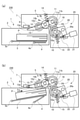
本開示に係る画像形成装置201は、図1に示すように、電子写真方式の画像形成部201Bを搭載したレーザープリンタである。画像形成装置本体(以下、装置本体とする)201Aの上方には画像読取装置202が略水平に設置されている。画像読取装置202と装置本体201Aとの間に、シート排出用の排出空間Sが形成されている。
As shown in FIG. 1, the
装置本体201Aの下部には、シートPを収納する給送カセット1と、給送カセット1からシートPを給送する給送ユニット5と、をそれぞれ備える複数のシート給送部230が配置されている。各給送ユニット5は、給送カセット1からシートPを送り出すピックアップローラ12と、ピックアップローラ12からシートPを受取って給送するフィードローラ11と、を備える。また、シート給送部230には、フィードローラ11に当接するリタードローラ10が設けられている。フィードローラ11によって給送されるシートPは、リタードローラ10によって他のシートPから分離された状態で1枚ずつ搬送され、搬送ローラ対17を介してレジストレーションローラ対240へ向けて上方に搬送される。また、装置本体201Aの側部には、装置本体201Aに対して開閉可能な手差しトレイ29と、手差しトレイ29に載置されたシートPを給送する給送ユニット130と、を備える手差しシート給送部250が配置されている。
At the lower part of the apparatus
画像形成手段としての画像形成部201Bは、4ドラムフルカラー方式の電子写真ユニットである。即ち、画像形成部201Bは、レーザスキャナ210と、イエロー(Y)、マゼンタ(M)、シアン(C)及びブラック(K)の4色のトナー画像を形成する4個のプロセスカートリッジPY,PM,PC,PKを備える。各プロセスカートリッジPY~PKは、感光体である感光ドラム212、帯電手段である帯電器213、及び現像手段である現像器214を備えている。また、画像形成部201Bは、プロセスカートリッジPY~PKの上方に配された中間転写ユニット201Cと、定着部220とを備えている。中間転写ユニット201Cの上方には、現像器214にトナーを供給するためのトナーカートリッジ215が装着されている。
The
中間転写ユニット201Cは、駆動ローラ216a及びテンションローラ216bに巻き掛けられた中間転写ベルト216を備えている。中間転写ベルト216の内側には、各感光ドラム212に対向した位置で中間転写ベルト216に当接する一次転写ローラ219が設けられている。中間転写ベルト216は、不図示の駆動部により駆動される駆動ローラ216aによって図中反時計回り方向に回転し、感光ドラム212に担持された負極性のトナー像は一次転写ローラ219により順次中間転写ベルト216に多重転写される。
The
中間転写ユニット201Cの駆動ローラ216aと対向する位置には、中間転写ベルト216に担持されたカラー画像をシートPに転写する二次転写ローラ217が設けられている。二次転写ローラ217の上方に定着部220が配置され、定着部220の上方には第1排出ローラ対225a、第2排出ローラ対225b及び両面反転部201Dが配置されている。両面反転部201Dは、正逆転可能な反転ローラ対222、及び一面に画像が形成されたシートを再度、画像形成部201Bに搬送する再搬送通路R等が設けられている。また、画像形成装置201には、画像形成動作及びシート給送動作等を制御する制御手段として、制御部260が搭載されている。
At a position facing the
次に、画像形成装置201の画像形成動作について説明する。原稿の画像情報は画像読取装置202によって読み取られ、制御部260によって画像処理された後、電気信号に変換されて画像形成部201Bのレーザスキャナ210に伝送される。画像形成部201Bでは、帯電器213によって表面が所定の極性・電位に一様に帯電させられた感光ドラム212にレーザスキャナ210からのレーザ光が照射され、ドラムの回転に伴ってドラム表面が露光される。これにより、各プロセスカートリッジPY~PKの感光ドラム212の表面に、イエロー、マゼンタ、シアン及びブラックの単色画像に対応する静電潜像が形成される。これら静電潜像は、現像器214から供給される各色トナーにより現像されて可視化された後、一次転写ローラ219に印加される一次転写バイアスにより、感光ドラム212から中間転写ベルト216へと互いに重ね合わせて一次転写される。
Next, the image forming operation of the
このような動作に並行して、いずれかのシート給送部230,250からレジストレーションローラ対240へ向けて1枚ずつシートPが給送される。レジストレーションローラ対240は、シートPの斜行を補正した後、画像形成部201Bによるトナー像形成の進捗に合わせてシートPを二次転写ローラ217へ向けて送り出す。二次転写ローラ217と中間転写ベルト216との間に形成される転写部(二次転写部)において、二次転写ローラ217に印加される二次転写バイアスにより、シートPに対してフルカラーのトナー像が一括して二次転写される。トナー像が転写されたシートPは、定着部220に搬送され、定着部220において付与される熱及び圧力によって各色のトナーが溶融混色することで、トナー像はシートPにカラー画像として定着する。
In parallel with such an operation, the sheets P are fed one by one from one of the
この後、シートPは、定着部220の下流に設けられた第1排出ローラ対225a又は第2排出ローラ対225bによって排出空間Sに排出され、排出空間Sの底部に配置された排出部223に積載される。シートPの両面に画像を形成する際は、第1面に画像が形成されたシートPが反転ローラ対222により反転した状態で再搬送通路Rに搬送され、再度、画像形成部201Bに搬送される。そして、画像形成部201Bによって第2面に画像を形成されたシートPは、第1排出ローラ対225a又は第2排出ローラ対225bによって排出部223に排出される。
After that, the sheet P is discharged to the discharge space S by the first
なお、上述の画像形成部201Bは画像形成手段の一例であり、感光体に形成したトナー像をシートに直接転写する直接転写方式の電子写真ユニットを用いてもよく、インクジェット方式やオフセット印刷方式の画像形成手段を用いてもよい。
The
(ふくらみのあるシートの詰まり)
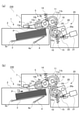
ところで、従来、封筒や薬袋等のようなシート、又はカールした状態のシート等、厚さ方向のふくらみを持つシートを給送する場合に、シート詰まりが発生することがあった。図2(a)、(b)は、ふくらみのあるシートP1,P2が、シート給送部230のフィードローラ11とリタードローラ10との間に形成される分離ニップ24に向けて給送されている様子を表している。分離ニップ24とは、フィードローラ11とリタードローラ10とが接触している領域を指し、図面上は、2つのローラ10,11の軸線方向から視て、ローラ10,11の共通接線T1とローラ10,11の軸線を結ぶ直線T2との交点として表している。
(Clogged sheet with bulge)
By the way, conventionally, when a sheet having a bulge in the thickness direction such as a sheet such as an envelope or a medicine bag or a sheet in a curled state is fed, sheet clogging may occur. In FIGS. 2A and 2B, the bulging sheets P1 and P2 are fed toward the separation nip 24 formed between the
図2(a)に示すように、封等や薬袋のように一部が折り返された形状のシートP1は、厚さが不均一となり、先端部E1(シート給送方向の下流端)がふくらんだ形状となっている場合がある。また、シートの保管状況や、コート紙のように片面に表面処理が施されていること等の理由により、図2(b)に示すようにシートP2の先端部E2がカールしている場合がある。これらの場合において、シートP1,P2の先端部E1,E2が、分離ニップ24における搬送方向(T1)に対して傾斜した状態で分離ニップ24に接近すると、先端部E1,E2が分離ニップ24を通過できず、シート詰まりが発生することがあった。 As shown in FIG. 2A, the sheet P1 having a partially folded shape such as a seal or a medicine bag has a non-uniform thickness, and the tip portion E1 (downstream end in the sheet feeding direction) is bulged. It may have a shape. In addition, the tip E2 of the sheet P2 may be curled as shown in FIG. 2B due to the storage condition of the sheet, the surface treatment on one side like coated paper, and the like. be. In these cases, when the tips E1 and E2 of the sheets P1 and P2 approach the separation nip 24 in a state of being inclined with respect to the transport direction (T1) in the separation nip 24, the tips E1 and E2 move the separation nip 24. It could not pass and the sheet was sometimes clogged.
シート詰まりの原因は、次のように説明することができる。シートP1,P2の先端部E1,E2の角度θがリタードローラ10に向かって傾斜している場合、先端部E1,E2は分離ニップ24より上流でリタードローラ10に当接する。このとき、シートP1,P2がリタードローラ10を押圧する力fの一部は、リタードローラ10の周面に垂直な向きに作用し、その分リタードローラ10の周面に沿った向きに作用する力の成分が小さくなる。従って、シートが接線T1に水平な姿勢(θ=0)で搬送される場合に比べて、フィードローラ11からシートを介して伝わるリタードローラ10を回転させようとする力が小さくなり、リタードローラ10がフィードローラ11に連れ回りにくくなる。その結果、フィードローラ11が回転を継続しても、先端部E1,E2がリタードローラ10に引っ掛かった状態でシートP1,P2が移動を停止してしまう。
The cause of the sheet clogging can be explained as follows. When the angle θ of the tip portions E1 and E2 of the sheets P1 and P2 is inclined toward the
そこで、以下の各実施例では、シートの分離性能を確保しつつ、封筒等のシートを給送する場合のシート詰まりを低減するための構成を設けている。 Therefore, in each of the following embodiments, a configuration is provided for reducing sheet clogging when feeding sheets such as envelopes while ensuring sheet separation performance.
まず、第1の実施形態(実施例1)に係るシート給送部230について図3~図8を用いて説明する。図3はシート給送部230の概略図であり、(a)は給送動作を行う前の待機状態を表し、(b)はシート積載板3によってシートPが持ち上げられた状態を表している。
First, the
図3(a)、(b)に示すように、給送カセット1は、シートPが積載されるシート積載部として、カセット本体2の底部に対して昇降可能なシート積載板3を備えている。シート積載板3は、回動軸3aを中心にして上下方向(鉛直方向)に回動可能であり、下面をリフタ板4に支持されている。リフタ板4は、後述のリフタモータ26により駆動されてリフタ板回動軸4aを回転中心にして上下方向に回動することで、シート積載板3を昇降させる。なお、給送カセット1は、シート給送装置の筐体を兼ねる画像形成装置201の装置本体201Aに対し、図3の紙面に対して垂直な方向に挿入及び引出可能である。
As shown in FIGS. 3A and 3B, the
給送ユニット5は、ピックアップローラ12と、給送回転体に相当するフィードローラ11とによって構成される。フィードローラ11に当接するリタードローラ10及びその離間機構25については、後に詳しく説明する。ピックアップローラ12は、保持部材であるピックアップホルダ13により、回転可能に保持されている。ピックアップホルダ13は、フィードローラ11のローラ軸11aを中心にして上下方向に回動可能(移動可能)であり、付勢部材であるピックアップバネ14により下方に向けて付勢されている。ピックアップホルダ13は不図示の昇降機構により、シートを給送しない場合は、ピックアップローラ12をシートから離間した位置に持ち上げるようにする。
The
フィードローラ11はローラ軸11aに取付けられ、後述の給送モータ27からローラ軸11aに伝達される駆動力によって回転する。ローラ軸11aには第1ギヤ11bが取り付けられ、ピックアップホルダ13には、アイドラギヤである第2ギヤ9bを支持する回転軸9aと、第3ギヤ12b及びピックアップローラ12を支持するローラ軸12aが設けられている。ローラ軸11aに入力された回転は、第1ギヤ11bから第2ギヤ9bを介して第3ギヤ12bに伝達される。これにより、フィードローラ11とピックアップローラ12とが、シート給送方向Fdに沿った方向(図中反時計回り方向)に回転駆動される。また、フィードローラ11及びピックアップローラ12は、それぞれワンウェイクラッチを介してローラ軸11a,12aに連結されており、シート給送方向Fdとは逆方向のトルクを受けた場合は空転するように構成されている。
The
ピックアップホルダ13にはフラグ部13aが設けられており、装置本体201Aに固定される給送フレーム7にはフラグ部13aを検知可能な光電センサ等のシート高さセンサ8が設けられている。シート高さセンサ8は、フラグ部13aを検知することで、シート積載板3に積載されたシートPの上面が上下方向において所定の位置にあるか否かを判定することができる。ただし、所定の位置さとは、シートPの上面がピックアップ動作に適した圧力でピックアップローラ12に当接する位置(図3(b)参照)を指す。以下、シート高さセンサ8が光電センサであるものとして、フラグ部13aがシート高さセンサ8を遮光しているときをセンサのオン状態とし、遮光していないときをオフ状態とする。
The
分離部材に相当するリタードローラ10は、不図示のトルクリミッタを介してリタードローラ軸10aに取り付けられており、給送ユニット5と共通の給送モータ27からシート給送方向Fdに連れ回る方向とは逆方向の駆動力を入力される。リタードローラ10は付勢手段としてのリタードバネ15によってフィードローラ11に圧接され、フィードローラ11との間に、シートPの分離を行う分離部として分離ニップ24を形成している。分離ニップ24に1枚のみのシートPが存在する場合、シートPはフィードローラ11及びピックアップローラ12から受ける搬送力によってシート給送方向Fdに移動し、リタードローラ10はトルクリミッタが滑ることでフィードローラ11に連れ回る。一方、分離ニップ24に複数枚のシートPが存在する場合、リタードローラ10はトルクリミッタを介して受取る駆動力によってシート給送方向Fdとは逆方向に回転し、最上位のシートP以外のシートPをシート給送方向Fdの上流に押し戻す。
The
分離ニップ24の近傍には、シート給送方向Fdにおいて分離ニップ24より下流の検知位置でシートPを検知するニップセンサ16が設けられている。シート検知手段の一例であるニップセンサ16は、例えばシートPの搬送路に向けてレーザ光を照射し、シートPからの反射光を検知する反射型の光電センサである。以下、検知位置にシートPが存在し、シートPによりニップセンサ16が反射光を検知しているときをオン状態とし、検知位置にシートPが存在せず、反射光が検知されていないときをオフ状態とする。
In the vicinity of the separation nip 24, a
(離間機構)
ここで、ふくらみを持つシートを給送する場合、予めフィードローラ11とリタードローラ10とを離間させ、分離ニップ24を開放しておくことが有効である。上述した通り、ふくらみを持つシートを給送する場合(図2(a)、(b)参照)、シートP1,P2の先端部E1,E2が分離ニップ24より上流でリタードローラ10に引っ掛かってしまい、分離ニップ24を通過できない場合がある。分離ニップ24を開放させておくことで、シートの先端部E1,E2とリタードローラ10との接触位置がシート給送方向の下流側に変化するため、リタードローラ10がフィードローラ11に連れ回りやすくなり、シート詰まりが生じる可能性が減少する。
(Separation mechanism)
Here, when feeding a sheet having a bulge, it is effective to separate the
なお、フィードローラ11とは逆の回転方向に駆動されるリタードローラ10は摩擦力によってシートを分離する分離部材の一例であり、装置本体に固定された軸にトルクリミッタを介して接続されたローラ部材や、パッド部材を分離部材として用いてもよい。これらの場合においても、分離部材をフィードローラ11から離間させておくことでシートが分離ニップを容易に通過できるようになるため、シート詰まりが発生する可能性を低減可能である。
The
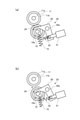
離間手段に相当する離間機構25について、図4(a)、(b)を用いて説明する。離間機構25は、離間アーム20と、ソレノイド21と、復帰バネ22とによって構成される。揺動部材である離間アーム20はアーム回動軸20aを介して給送フレーム7に支持されており、リタードローラ軸10aの軸受部材に係合可能である。ソレノイド21には復帰バネ22が接続され、ソレノイド21のプランジャを中立位置(図4(a)の位置)に付勢している。
The
図4(a)に示すようにソレノイド21がオフ状態(非通電状態)のとき、リタードローラ軸10aはリタードバネ15によってフィードローラ11に向けて付勢され、フィードローラ11及びリタードローラ10は圧接した状態になる。図4(b)に示すようにソレノイド21がオン状態(通電状態)のとき、離間アーム20がリタードバネ15の付勢力に抗して揺動し、リタードローラ10のローラ軸10aを押圧する。これにより、リタードローラ10はフィードローラ11から離間し、分離ニップ24(図4(a)参照)は開放される。なお、離間機構25は給送回転体と分離部材とを離間可能な離間手段の一例であり、上述の離間機構25とは異なる構成の離間手段を用いてもよい。例えば、リタードローラ10の軸位置を固定し、フィードローラ11を移動させる構成としてもよい。
As shown in FIG. 4A, when the
以下、フィードローラ11及びリタードローラ10が当接した状態(図4(a))を分離ニップ24の当接状態とし、フィードローラ11及びリタードローラ10が離間した状態(図4(b))を分離ニップ24の離間状態(開放状態)とする。離間状態におけるリタードローラ10とフィードローラ11との間の距離は、例えば、封筒又は薬袋一枚分の厚さ(例えば0.5~2[mm])又はそれ以上の値に設定される。
Hereinafter, the state in which the
シート給送部230の制御構成について説明する。シート給送部230は、画像形成装置201の装置本体201Aに搭載される制御部260(図1参照)によって制御されている。図5に示すように、制御部260は、プログラムを実行可能な実行手段としての中央演算装置(CPU)261と、プログラム及び設定情報等のデータを記憶する記憶部としてのメモリ262と、を備える。制御部260は、上述の給送モータ27、リフタモータ26、ソレノイド21、シート高さセンサ8、及びニップセンサ16の他、液晶ディスプレイ等の操作画面31に接続されている。シートの種類を入力可能な入力手段に相当する操作画面31は、各段の給送カセット1及び手差しトレイ29にセットしたシートの種類(例えば普通紙、厚紙、封筒等)をユーザが選択可能な画面を表示し、ユーザの選択操作を受付ける。制御部260は、操作画面31に対するユーザの操作に基づいて、シートの種類の情報を各段の給送カセット1及び手差しトレイ29のそれぞれに関連付けてメモリ262に格納する。
The control configuration of the
(シートのふくらみの検知方法)
ところで、ふくらみのあるシートの不送りを回避するためには、分離ニップ24を開放させた状態でシートの先端部に分離ニップ24を通過させることが有効であるが、常に分離ニップ24を開放させておくと、シートの重送が発生する虞がある。即ち、普通紙等のふくらみがないシートを給送する場合に、リタードローラ10がシートを十分に分離することができず、複数枚のシートが重なった状態のままで分離ニップ24より下流の搬送部材に到達する可能性がある。
(How to detect the bulge of the sheet)
By the way, in order to avoid non-feeding of a bulging sheet, it is effective to pass the separation nip 24 through the tip of the sheet with the separation nip 24 open, but the separation nip 24 is always opened. If this is done, there is a risk that double feeding of the sheet will occur. That is, when feeding a sheet having no bulge such as plain paper, the
そこで、本実施例では、給送モータ27によって給送ユニット5が駆動される際のピックアップローラ12の沈み込みを利用してシートのふくらみの有無を判断し、判断の結果に基づいて給送動作のモードを切換える構成とした。
Therefore, in this embodiment, the presence or absence of swelling of the seat is determined by utilizing the sinking of the
シートPの給送が行われる場合、給送モータ27による給送ユニット5の駆動開始に先立って、シート高さセンサ8がオン状態となる位置までシート積載板3が上昇する(図3(b))参照)。以下説明するように、給送モータからフィードローラ11のローラ軸11aに駆動力が入力されると、ピックアップバネ14の付勢力とは別に、ギヤの歯面の押し合いに起因する力によってピックアップローラ12が下方に付勢される。
When the seat P is fed, the
図6はフィードローラ11のローラ軸11aの軸線方向から視た給送ユニット5の模式図である。第1ギヤ11b、第2ギヤ9b、第3ギヤ12bの回転軸線をO1,O2,O3とし、第1ギヤ11bと第2ギヤ9bの軸間距離をL1とし、第1ギヤ11bと第3ギヤ12bの軸間距離をL2とする。各ギヤの軸位置は、2L1>L2の関係が満たされるように配置されている。
FIG. 6 is a schematic view of the
給送モータ27からの駆動力によって第1ギヤ11bが図中反時計回り方向に回転すると、アイドラギヤである第2ギヤ9bが時計回り方向に回転し、第3ギヤ12bが反時計回り方向に回転する。このとき、第1ギヤ11bと第2ギヤ9bの噛み合い面において、第2ギヤ9bは大きさFの力で下方に押圧され(作用)、第1ギヤ11bは大きさFの力で上方に押し返される(反作用)。また、第2ギヤ9bと第3ギヤ12bの噛み合い面において、第3ギヤ12bは大きさFの力で上方に押圧され(作用)、第2ギヤ9bは大きさFの力で下方に押し返される(反作用)。
When the
モーメントのつり合いから、第2ギヤ9bの回転軸9aには大きさが2Fの下向きの力が作用し、ピックアップローラ12のローラ軸12aには大きさがFの上向きの力が作用すると見なすことができる。従って、ピックアップホルダ13には、フィードローラ11のローラ軸11aを中心として、反時計回り方向を正の向きとして、次のモーメントMが作用する。
M=2F×L1-F×L2=F(2L1-L2)
From the balance of moments, it can be considered that a downward force having a magnitude of 2F acts on the
M = 2F x L1-F x L2 = F (2L1-L2)
ここで、各ギヤの回転軸線O1~O3の位置が2L1>L2となるように構成されているため、ピックアップホルダ13にかかるモーメントMはM>0となる。そして、ピックアップホルダ13が図中反時計回り方向に回動しようとすることから、ピックアップローラ12がシートPの上面を押圧する力が増大する。なお、図示した例では各ギヤ9b、11b、12bの軸線O1,O2,O3が直線状に並ぶ構成について説明したが、ピックアップホルダ13の回動方向におけるモーメントについて上述の関係が満たされていれば同様の結果となる。
Here, since the positions of the rotation axes O1 to O3 of each gear are configured to be 2L1> L2, the moment M applied to the
上述の構成により、図7(a)に示すようにシートPが封筒、薬袋、又はカールしたシート等のふくらみを有するものである場合、給送モータ27の駆動開始に伴ってピックアップローラ12の押圧力が増大する。すると、図7(b)に示すようにシートPの上面がピックアップローラ12に押圧されて下方に沈み込む。このとき、ピックアップホルダ13に備えられたフラグ部13aがシート高さセンサ8の検知領域から外れると、シート高さセンサ8がオン状態からオフ状態に切換わる。これにより、シート積載板3に積載されたシートPがふくらみを持つかどうかを検知することが可能となる。
With the above configuration, when the sheet P has a bulge such as an envelope, a medicine bag, or a curled sheet as shown in FIG. 7A, the
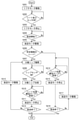
(給送動作の制御方法)
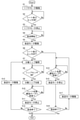
このような検知機構を用いて、シート給送部230によるシートの給送動作を制御する方法について、図8のフローチャートにそって説明する。なお、フローチャートの各工程は、制御部260(図5参照)のCPU261がメモリ262に記憶されたプログラムを読出して実行することで実現される。
(Control method of feeding operation)
A method of controlling the sheet feeding operation by the
ユーザがシートPをシート積載板3に積載し、装置本体201Aに給送カセット1を装着すると、装置本体201Aに設けられたセンサが給送カセット1の装着を検知する。すると、CPU261はリフタモータ26を回転させ、シート積載板3の上昇を開始させる(S1)。シート高さセンサ8がオンになる位置までシート積載板3が上昇すると(S2のYes)、CPU261はリフタモータ26を停止させ(S3)、シート給送動作の開始まで待機する。待機状態において、リタードローラ10はフィードローラ11に圧接しているものとする。
When the user loads the sheet P on the
外部PCから画像形成装置201に画像の出力を指示する信号(画像形成ジョブ)が入力された場合や、ユーザが画像読取装置202(図2参照)に原稿をセットしてコピーボタンを押圧した場合等に、給送動作は開始される(S4のYes)。このとき、CPU261は、1枚目のシートを給送するために給送モータ27の回転を開始させると共に(S5)、シート高さセンサ8の検知信号に基づいて給送対象のシートがふくらみを有するものであるかどうかを判断する(S6)。
When a signal (image forming job) instructing image output is input from an external PC to the
普通紙等の平坦なシートがシート積載板3に積載されている場合、給送モータ27の駆動力によってピックアップローラ12が下方に付勢されてもシートの上面の沈み込みは生じず、シート高さセンサ8はオン状態を維持する。この場合、CPU261は給送対象のシートがふくらみを持たないと判断し(S6のNo)、離間機構25の状態を変化させることなく、給送モータ27の回転を継続させて給送ユニット5にシートを給送させる。そして、分離ニップ24より下流側の搬送ローラ対(例えば、図2の搬送ローラ対17)にシートが到達したと判断すると(S14のYes)、CPU261は給送モータ27を停止させる(S15)。下流側の搬送ローラ対への到達タイミングは、例えば、当該搬送ローラ対の付近に配置されたセンサや、ニップセンサ16によるシートの検知タイミング及び給送ユニット5によるシートの搬送速度(フィードローラ11の周速)によって判断可能である。2枚目のシートを給送する場合(S16のNo)は、再び給送モータ27の回転が開始され(S17)、必要な枚数のシートが給送されるまで同様の給送動作(S14~S16)が繰り返し行われる。
When a flat sheet such as plain paper is loaded on the
一方、1枚目のシートを給送する際に、給送モータ27の回転を開始させた後シート高さセンサ8がオン状態からオフ状態に変わった場合、CPU261は給送対象のシートがふくらみを有していると判断する(S6のYes)。この場合、給送モータ27の回転が継続している状態で、離間機構25のソレノイド21に通電されることでリタードローラ10がフィードローラ11から離間し、分離ニップ24が開放される(S7)。シートは、主にピックアップローラ12から受ける搬送力により、離間状態の分離ニップ24に進入する。
On the other hand, when the first sheet is fed, if the
そして、ニップセンサ16がオフからオンに切り替わることでシート先端が分離ニップ24を通過したことが検知されると(S8のYes)、CPU261はソレノイド21への通電を終了し、リタードローラ10をフィードローラ11に当接させる(S9)。これにより、分離ニップ24においてフィードローラ11及びリタードローラ10にシートが挟持された状態となる。そして、シートがピックアップローラ12及びフィードローラ11の両方から搬送力を得て画像形成部201Bへ向けて搬送される一方、給送中のシートの下に重なるシートはリタードローラ10によってシート給送方向の上流側に押し戻される。
Then, when it is detected that the seat tip has passed through the separation nip 24 by switching the
その後、分離ニップ24より下流側の搬送ローラ対にシートが到達したと判断すると(S10のYes)、CPU261は給送モータ27を停止させる(S11)。2枚目のシートを給送する場合(S12のNo)は、再び給送モータ27の回転が開始され(S13)、必要な枚数のシートが給送されるまで同様の給送動作(S7~S12)が繰り返し行われる。このとき、シートがふくらみを有することは既に判明しているため、2枚目以降のシートを給送する際も、離間機構25によって分離ニップ24を開放した状態でシートを給送させ、その後、分離ニップ24を当接状態とする動作(S7~S9)が行われる。
After that, when it is determined that the sheet has reached the transport roller pair on the downstream side of the separation nip 24 (Yes in S10), the
(本実施例の効果)
このように、本実施例では、シート高さセンサ8を用いてピックアップローラ12(押圧部)がシートの上面を押圧した際のシートの変位を検知し、検知結果に基づいてシート給送部230による給送動作の内容を切換える制御が行われる。言い換えると、検知手段(シート高さセンサ8)の検知結果に基づいて、第1の給送モード(S7~S13)及び第2の給送モード(S14~S17)のいずれを実行するかが決定される。
(Effect of this example)
As described above, in this embodiment, the displacement of the seat when the pickup roller 12 (pressing portion) presses the upper surface of the seat is detected by using the
第1の給送モードでは、分離ニップ24(分離部)が開放された状態でシート先端が分離ニップ24の位置を通過するように、離間機構25(離間手段)の動作が制御される。これにより、封筒や薬袋等のふくらみを持ち、分離ニップ24に突入する際の抵抗が大きいシートの不送りが生じる可能性が低減される。一方、第2の給送モードでは、分離ニップ24が当接状態に維持されている状態で、シート先端が当接状態の分離ニップ24を通過する。これにより、普通紙等のふくらみの無いシートについて、重送の発生を防ぐことができる。従って、本実施例の構成により、シートの重送が生じる可能性を最小限に抑えつつ、封筒等のシートの不送りの発生を低減することができる。 In the first feeding mode, the operation of the separation mechanism 25 (separation means) is controlled so that the sheet tip passes through the position of the separation nip 24 in a state where the separation nip 24 (separation portion) is open. This reduces the possibility of non-feeding of a sheet that has a bulge such as an envelope or a medicine bag and has a large resistance when plunging into the separation nip 24. On the other hand, in the second feeding mode, the sheet tip passes through the separation nip 24 in the contact state while the separation nip 24 is maintained in the contact state. As a result, it is possible to prevent the occurrence of double feeding for a sheet having no bulge such as plain paper. Therefore, according to the configuration of this embodiment, it is possible to reduce the occurrence of non-feeding of sheets such as envelopes while minimizing the possibility of double feeding of sheets.
また、本実施例では、シートの上面を押圧可能な押圧部が、給送ユニット5の一部(ピックアップローラ12)として構成され、フィードローラ11(給送回転体)の駆動に伴って下方に移動するように構成されている。従って、シートを給送するための構成を、シートのふくらみの有無を検知するための構成として兼用する構成となっている。 Further, in the present embodiment, the pressing portion capable of pressing the upper surface of the sheet is configured as a part of the feeding unit 5 (pickup roller 12), and is lowered as the feed roller 11 (feeding rotating body) is driven. It is configured to move. Therefore, the configuration for feeding the seat is also used as the configuration for detecting the presence or absence of swelling of the seat.
(変形例)
以上の実施例1では、ピックアップローラ12によってシート積載板3から繰り出されたシートが、フィードローラ11とリタードローラ10の間の分離ニップ24を経由して給送される構成について説明したが、構成の異なる給送ユニットを用いてもよい。例えば、給送回転体としてベルト部材を用いると共に、ベルト部材に当接するリタードローラによってシートを分離してもよい。また、給送ユニットはピックアップローラ12を備えたものに限らず、フィードローラ11がシート積載板3に積載されたシートに直接当接して給送するものであってもよい。その場合、フィードローラ11が駆動される際に、ピックアップローラ12の代わりにシートの上面を押圧する部材を押圧部として設けてもよい。
(Modification example)
In the above-mentioned first embodiment, the configuration in which the sheet unwound from the
次に、第2の実施形態(実施例2)に係るシート給送装置について、図9を用いて説明する。本実施例に係るシート給送装置は、操作画面31(図5参照)等の入力手段を介して入力されるシートの種類に基づいて給送動作が制御される点で上記実施例1と異なっている。その他の、実施例1のものと構成及び作用が等しい要素には、実施例1と共通の符号を付して説明を省略する。 Next, the sheet feeding device according to the second embodiment (Example 2) will be described with reference to FIG. The sheet feeding device according to the present embodiment is different from the first embodiment in that the feeding operation is controlled based on the type of the sheet input via the input means such as the operation screen 31 (see FIG. 5). ing. Other elements having the same configuration and operation as those of the first embodiment are designated by the same reference numerals as those of the first embodiment, and the description thereof will be omitted.
図9のステップS206に示すように、本実施例では、シート積載板3に積載されたシートの種類として設定された情報に基づいて、予め設定された所定の種類のシートを給送する場合に第1の給送モードを実行するように構成される。所定の種類のシートとは、当接状態の分離ニップ24に突入させた場合の抵抗が大きいシートであり、封筒や薬袋の他、例えば表面をエンボス加工されたエンボス紙や、片面に樹脂コーティングが施されたコート紙を含めることができる。また、第1の給送モードが実行されるシートの種類を、操作画面31を介してユーザが明示的に選択できるように構成してもよい。
As shown in step S206 of FIG. 9, in this embodiment, when a predetermined type of sheet set in advance is fed based on the information set as the type of sheet loaded on the
以下、図9のフローチャートに沿って本実施例における給送動作の制御方法を説明する。なお、シート積載板3に積載されたシートの種類の情報は、制御部260が初期値を自動的に選択するような場合を含めて、給送動作の開始前に予め設定されているものとする。
Hereinafter, a method of controlling the feeding operation in this embodiment will be described with reference to the flowchart of FIG. The information on the type of sheet loaded on the
ユーザがシートPをシート積載板3に積載し、装置本体201Aに給送カセット1を装着すると、装置本体201Aに設けられたセンサが給送カセット1の装着を検知する。すると、CPU261はリフタモータ26を回転させ、シート積載板3の上昇を開始させる(S201)。シート高さセンサ8がオンになる位置までシート積載板3が上昇すると(S202のYes)、CPU261はリフタモータ26を停止させ(S203)、シート給送動作の開始まで待機する。待機状態において、リタードローラ10はフィードローラ11に圧接しているものとする。
When the user loads the sheet P on the
給送動作を開始する場合(S204のYes)、CPU261は、1枚目のシートを給送するために給送モータ27の回転を開始させる(S205)。そして、シートの供給元として選択されている給送カセット1又は手差しトレイ29(図2参照)について、設定されているシートの種類が所定の種類であるかどうかを判定する(S206)。
When starting the feeding operation (Yes in S204), the
給送対象のシートが所定の種類ではない場合(S206のNo)、つまりふくらみを持たない一般的なシートである場合、CPU261は離間機構25の状態を変化させることなく、給送モータ27の回転を継続させて給送ユニット5にシートを給送させる。そして、分離ニップ24より下流側の搬送ローラ対にシートが到達したと判断すると(S214のYes)、CPU261は給送モータ27を停止させる(S215)。2枚目のシートを給送する場合(S216のNo)は、再び給送モータ27の回転が開始され(S217)、必要な枚数のシートが給送されるまで同様の給送動作(S214~S216)が繰り返し行われる。
When the sheet to be fed is not of a predetermined type (No in S206), that is, when it is a general sheet having no bulge, the
一方、給送対象のシートが所定の種類である場合(S206のYes)、つまりふくらみを有するシートである場合、CPU261は給送モータ27の回転が継続している状態で離間機構25を作動させ、分離ニップ24を開放させる(S207)。シートは、主にピックアップローラ12から受ける搬送力により、離間状態の分離ニップ24に進入する。
On the other hand, when the sheet to be fed is of a predetermined type (Yes in S206), that is, when the sheet has a bulge, the
そして、ニップセンサ16がオフからオンに切り替わることでシート先端が分離ニップ24を通過したことが検知されると(S208のYes)、CPU261は離間機構25の作動を解除する(S209)。これにより、リタードローラ10がフィードローラ11に当接し、分離ニップ24においてフィードローラ11及びリタードローラ10にシートが挟持された状態となる。そして、シートがピックアップローラ12及びフィードローラ11の両方から搬送力を得て画像形成部201Bへ向けて搬送される一方、給送中のシートの下に重なるシートはリタードローラ10によってシート給送方向の上流側に押し戻される。
Then, when it is detected that the seat tip has passed through the separation nip 24 by switching the
その後、分離ニップ24より下流側の搬送ローラ対にシートが到達したと判断すると(S210のYes)、CPU261は給送モータ27を停止させる(S211)。2枚目のシートを給送する場合(S212のNo)は、再び給送モータ27の回転が開始され(S213)、必要な枚数のシートが給送されるまで同様の給送動作(S207~S212)が繰り返し行われる。このとき、シートが所定の種類であることは既に判明しているため、2枚目以降のシートを給送する際も、離間機構25によって分離ニップ24を開放した状態でシートを給送させた後、分離ニップ24を当接状態とする動作(S207~S209)が行われる。
After that, when it is determined that the sheet has reached the transport roller pair on the downstream side of the separation nip 24 (Yes in S210), the
このように、本実施例では、シート積載板3に積載されたシートの種類に基づいて、シート給送部230による給送動作の内容を切換える制御が行われる。言い換えると、入力手段(操作画面31)を介して入力されたシート種類に基づいて、第1の給送モード(S207~S213)及び第2の給送モード(S214~S217)のいずれを実行するかが決定される。
As described above, in this embodiment, control is performed to switch the content of the feeding operation by the
実施例1と同様、第1の給送モードでは、分離ニップ24(分離部)が開放された状態でシート先端が分離ニップ24の位置を通過するように、離間機構25(離間手段)の動作が制御される。これにより、封筒や薬袋等のシートの不送りが生じる可能性が低減される。一方、第2の給送モードでは、分離ニップ24が当接状態に維持されている状態で、シート先端が当接状態の分離ニップ24を通過する。これにより、普通紙等のふくらみの無いシートについて、重送の発生を防ぐことができる。従って、本実施例の構成により、シートの重送が生じる可能性を最小限に抑えつつ、封筒等のシートが詰まる可能性を低減することができる。 Similar to the first embodiment, in the first feeding mode, the separation mechanism 25 (separation means) is operated so that the sheet tip passes through the position of the separation nip 24 with the separation nip 24 (separation portion) open. Is controlled. This reduces the possibility of non-feeding of sheets such as envelopes and medicine bags. On the other hand, in the second feeding mode, the sheet tip passes through the separation nip 24 in the contact state while the separation nip 24 is maintained in the contact state. As a result, it is possible to prevent the occurrence of double feeding for a sheet having no bulge such as plain paper. Therefore, according to the configuration of this embodiment, it is possible to reduce the possibility of the sheet such as an envelope being clogged while minimizing the possibility of double feeding of the sheet.
また、本実施例では、シートの種類の設定情報が、所定のシートの種類に含まれるかどうかによって給送モードが切換わる構成としたため、設定情報が同じであれば同じ給送モードが選択される。従って、シートの積載枚数やシートの剛性等の要因に寄らずに安定した挙動を示すシート給送装置を提供することができる。 Further, in this embodiment, since the feeding mode is switched depending on whether the setting information of the sheet type is included in the predetermined sheet type, the same feeding mode is selected if the setting information is the same. To. Therefore, it is possible to provide a sheet feeding device that exhibits stable behavior regardless of factors such as the number of sheets loaded and the rigidity of the sheet.
次に、第3の実施形態(実施例3)に係るシート給送装置について、図10を用いて説明する。本実施例に係るシート給送装置は、分離ニップ24を当接状態としてシートの給送を開始した後、シートが分離ニップ24の通過に失敗した場合に分離ニップ24を開放させる点で上記実施例1,2と異なっている。その他の、実施例1,2のものと構成及び作用が等しい要素には、実施例1,2と共通の符号を付して説明を省略する。
Next, the sheet feeding device according to the third embodiment (Example 3) will be described with reference to FIG. The sheet feeding device according to the present embodiment is described above in that after the sheet feeding device is started with the separated
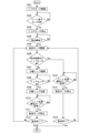
以下、図10のフローチャートに沿って本実施例における給送動作の制御方法を説明する。ユーザがシートPをシート積載板3に積載し、装置本体201Aに給送カセット1を装着すると、装置本体201Aに設けられたセンサが給送カセット1の装着を検知する。すると、CPU261はリフタモータ26を回転させ、シート積載板3の上昇を開始させる(S301)。シート高さセンサ8がオンになる位置までシート積載板3が上昇すると(S302のYes)、CPU261はリフタモータ26を停止させ(S303)、シート給送動作の開始まで待機する。待機状態において、リタードローラ10はフィードローラ11に圧接しているものとする。
Hereinafter, a method of controlling the feeding operation in this embodiment will be described with reference to the flowchart of FIG. When the user loads the sheet P on the
給送動作を開始する場合(S304のYes)、CPU261は、1枚目のシートを給送するために給送モータ27の回転を開始させる(S305)。そして、給送モータ27の駆動開始から所定時間が経過したタイミングで、ニップセンサ16(図3(a)参照)の検知信号を確認する(S306)。ただし、所定時間とは、ピックアップローラ12及びフィードローラ11がシートに対してスリップせずに搬送された場合に、給送モータ27の駆動開始からシートの先端がニップセンサ16の検知位置に到達するまでの所要時間である。即ち、シート積載板3にセットされたシートの先端位置からニップセンサ16の検知位置までの距離をXとし、給送動作におけるピックアップローラ12及びフィードローラ11の周速をVとして、X/Vの長さの時間を所定時間として用いることができる。
When starting the feeding operation (Yes in S304), the
給送モータ27の駆動開始から所定時間内にニップセンサ16がシートを検知した場合(S306のYes)、CPU261はシートがスリップせずに搬送されていると判断する。この場合、CPU261は離間機構25の状態を変化させることなく、給送モータ27の回転を継続させて給送ユニット5にシートを給送させる。そして、分離ニップ24より下流側の搬送ローラ対にシートが到達したと判断すると(S314のYes)、CPU261は給送モータ27を停止させる(S315)。2枚目のシートを給送する場合(S316のNo)は、再び給送モータ27の回転が開始される(S305)。
When the
一方、給送モータ27の駆動開始から所定時間が経過してもニップセンサ16がシートを検知しない場合(S306のNo)、CPU261は分離ニップ24においてシート詰まりが発生していると判断する。この場合、CPU261は給送モータ27の回転が継続している状態で離間機構25を作動させ、分離ニップ24を開放させる(S307)。すると、シートは主にピックアップローラ12から受ける搬送力により、離間状態の分離ニップ24に進入する。
On the other hand, if the
そして、ニップセンサ16がオフからオンに切り替わることでシート先端が分離ニップ24を通過したことが検知されると(S308のYes)、CPU261は離間機構25の作動を解除する(S309)。これにより、分離ニップ24においてフィードローラ11及びリタードローラ10にシートが挟持された状態となる。そして、シートがピックアップローラ12及びフィードローラ11の両方から搬送力を得て画像形成部201Bへ向けて搬送される一方、給送中のシートの下に重なるシートはリタードローラ10によってシート給送方向の上流側に押し戻される。なお、このとき、ピックアップローラ12をシートから離間させるようにしてもよい。この理由としては、フィードローラ11とリタードローラ10とが離間している間に、分離ニップ24に対応する位置に複数枚のシートが突入してしまっている可能性があるためである。分離ニップ24に対応する位置に複数枚のシートがある場合、リタードローラ10により、最上位シート以外のシートはシート給送方向の上流側に押し戻す必要がある。しかし、ピックアップローラ12がシートの上から押さえるような状態となっていると、ピックアップローラ12の上からの押圧力によりシートの押し戻しを阻害するおそれがある。そこで、シートの押し戻しの効果を大きくする方法としてピックアップローラ12をシートから離間させるようにする。
Then, when it is detected that the seat tip has passed through the separation nip 24 by switching the
その後、分離ニップ24より下流側の搬送ローラ対にシートが到達したと判断すると(S310のYes)、CPU261は給送モータ27を停止させる(S311)。2枚目のシートを給送する場合(S312のNo)は、再び給送モータ27の回転が開始される(S305)。
After that, when it is determined that the sheet has reached the transport roller pair on the downstream side of the separation nip 24 (Yes in S310), the
本実施例では、1枚のシートを給送する毎に、分離ニップ24におけるシート詰まりの有無が判定される(S306)。即ち、2枚目以降のシートのそれぞれに対して、給送モータ27の駆動開始から所定時間内にニップセンサ16がオフ状態からオン状態に切換わったかどうか判定され、判定結果によって給送動作の内容が切換わる。必要な枚数のシートが給送されると(S312,S316のYes)、給送動作が完了する。
In this embodiment, the presence or absence of sheet clogging in the separation nip 24 is determined each time one sheet is fed (S306). That is, for each of the second and subsequent sheets, it is determined whether or not the
このように、本実施例では、分離ニップ24を当接状態としてシートの給送を開始させた後、所定時間内にニップセンサ16がシートを検知しない場合に離間機構25によって分離ニップ24を開放する動作(S307)が行われる。言い換えると、給送回転体と分離部材とが当接している状態で給送ユニットにシートの給送を開始させた後、所定時間内にシート検知手段がシートを検知しない場合、離間手段によって給送回転体と分離部材とを離間させる動作が行われる。分離ニップ24を開放することで、シート先端が分離ニップ24の位置を通過して、シートが詰まった状態が解消される。従って、分離ニップ24におけるシートの分離作用を保ちつつ、分離ニップ24に突入する際の抵抗が大きい封筒等のシートであったとしても、シート詰まりが生じる可能性を低減することができる。
As described above, in this embodiment, after the sheet feeding is started with the separation nip 24 in the contact state, the separation nip 24 is opened by the
また、本実施例では、分離ニップ24が開放された後、ニップセンサ16がシートを検知すると、再びリタードローラ10がフィードローラ11に当接する。これにより、分離ニップ24が開放されている期間が最小限に抑えられるため、シートの重送が発生する可能性を抑えることができる。
Further, in this embodiment, when the
(その他の実施形態)
上記実施例1~3では、給送モータ27の駆動を継続している状態で離間機構25を作動させているが、例えば、給送モータ27を一時停止させた状態で離間機構25によって分離ニップ24を開放した後、給送モータ27の駆動を再開してもよい。このようにすることで、分離ニップ24を開放する動作の途中の状態で、ピックアップローラ12がシートをシート給送方向に搬送しようとする力が作用しない。そのため、例えば分離ニップ24が部分的に開放されているタイミングでシートがシート給送方向に押されることで、シートが斜行してしまう可能性を低減することができる。また、給送モータ27を一時停止させてから、リタードローラ10をフィードローラ11から離間させるまでの間に、ピックアップローラ12をシートの上面から離間させ、その後、ピックアップローラ12をシートに再び当接させる動作を行ってもよい。このように、シートとピックアップローラ12との離間、当接を行うことにより、シートを微小に振動させることができる。この振動により、例えばシートの先端が分離ニップ24の近傍で軽微に座屈しており、分離ニップ24に突入しにくくなっている状態が発生していた場合に、当該座屈を解消し、分離ニップ24に突入しやすくすることができる。
(Other embodiments)
In the first to third embodiments, the
また、実施例1~3で説明した要素を1つの装置に組み合わせて用いてもよい。例えば、シートの種類が設定されている場合にはシートの種類に基づいて給送モードを選択し(実施例2)、シートの種類が不特定又は不明である場合には、必要に応じて事後的に分離ニップ24を開放する(実施例3)構成としてもよい。 Further, the elements described in Examples 1 to 3 may be used in combination with one device. For example, if the seat type is set, the feeding mode is selected based on the seat type (Example 2), and if the seat type is unspecified or unknown, it is ex post facto as necessary. The separation nip 24 may be opened (Example 3).
また、実施例1~3では、画像形成装置201の装置本体201Aに組み込まれたシート給送装置であるシート給送部230について説明した。しかしながら、本技術は、手差し給送部250に対しても適用可能である。また、画像形成装置の筐体とは別に設けられるシート給送装置(例えば、画像形成装置の装置本体に隣接される大容量シート給送装置
や、画像読取装置に原稿となるシートを自動的に給送する原稿給送装置)に適用してもよい。
Further, in the first to third embodiments, the
本発明は、上述の実施形態の1以上の機能を実現するプログラムを、ネットワーク又は記憶媒体を介してシステム又は装置に供給し、そのシステム又は装置のコンピュータにおける1つ以上のプロセッサーがプログラムを読出し実行する処理でも実現可能である。また、1以上の機能を実現する回路(例えば、ASIC)によっても実現可能である。 The present invention supplies a program that realizes one or more functions of the above-described embodiment to a system or device via a network or storage medium, and one or more processors in the computer of the system or device reads and executes the program. It can also be realized by the processing to be performed. It can also be realized by a circuit (for example, ASIC) that realizes one or more functions.
3…シート積載部(シート積載板)/5…給送ユニット/8…検知手段(シート高さセンサ)/10…分離部材(リタードローラ)/11…給送回転体(フィードローラ)/12…押圧部、ピックアップローラ/13…保持部材(ピックアップホルダ)/16…シート検知手段(ニップセンサ)/24…分離部(分離ニップ)/25…離間手段(離間機構)/31…入力手段(操作画面)/201,230,250…シート給送装置(画像形成装置、シート給送部、手差しシート給送部)/201B…画像形成手段(画像形成部)/260…制御手段(制御部)
3 ... Seat loading unit (seat loading plate) / 5 ... Feeding unit / 8 ... Detection means (seat height sensor) / 10 ... Separation member (retard roller) / 11 ... Feeding rotating body (feed roller) / 12 ... Pressing unit, pickup roller / 13 ... Holding member (pickup holder) / 16 ... Seat detection means (nip sensor) / 24 ... Separation unit (separation nip) / 25 ... Separation means (separation mechanism) / 31 ... Input means (operation screen) / 201,230,250 ... Sheet feeding device (image forming device, sheet feeding section, manual feeding sheet feeding section) / 201B ... Image forming means (image forming section) / 260 ... Control means (control section)
Claims (14)
シートに当接して回転する給送回転体を有し、前記シート積載部に積載されたシートをシート給送方向に給送する給送ユニットと、
前記給送回転体に当接し、前記給送回転体によって給送されるシートを分離する分離部を前記給送回転体との間に形成する分離部材と、
前記給送回転体と前記分離部材とを離間させる離間手段と、
前記シート積載部に積載されたシートの上面を押圧可能な押圧部と、
前記押圧部が前記シート積載部に積載されたシートの上面を押圧した場合の、当該シートの上下方向における変位を検知可能な検知手段と、
前記離間手段により前記給送回転体と前記分離部材とを離間させた状態で、前記シート給送方向におけるシートの下流端が前記分離部の位置を通過するようにシートを給送する第1の給送モードと、前記給送回転体と前記分離部材とを当接させた状態で、シートの前記下流端が前記分離部を通過するようにシートを給送する第2の給送モードと、を含む複数のモードを実行可能な制御手段と、を備え、
前記制御手段は、前記検知手段の検知結果に基づいて、前記複数のモードの中のいずれかのモードを実行し前記シート積載部に積載されたシートを給送させる、
ことを特徴とするシート給送装置。 The seat loading section where the seats are loaded and
A feeding unit that has a feeding rotating body that rotates in contact with the seat and feeds the seat loaded on the seat loading portion in the seat feeding direction.
A separating member that abuts on the feeding rotating body and forms a separating portion for separating the sheet fed by the feeding rotating body between the feeding rotating body and the feeding rotating body.
A separating means for separating the feeding rotating body and the separating member, and
A pressing unit that can press the upper surface of the sheet loaded on the sheet loading unit, and a pressing unit that can press the upper surface of the sheet.
A detection means capable of detecting displacement in the vertical direction of the sheet when the pressing portion presses the upper surface of the sheet loaded on the sheet loading portion.
First, the sheet is fed so that the downstream end of the sheet in the sheet feeding direction passes through the position of the separating portion in a state where the feeding rotating body and the separating member are separated by the separating means. A feeding mode and a second feeding mode in which the sheet is fed so that the downstream end of the sheet passes through the separating portion in a state where the feeding rotating body and the separating member are in contact with each other. With control means capable of executing multiple modes, including
The control means executes any of the plurality of modes based on the detection result of the detection means, and feeds the sheet loaded on the sheet loading unit.
A sheet feeding device characterized by that.
前記押圧部が前記給送ユニットに設けられ、前記給送回転体が駆動される場合に下方に向かって移動するように構成され、
前記制御手段は、前記シート積載部に積載されたシートの上面が前記所定の位置にある状態で前記給送回転体の駆動を開始した後、前記検知手段がシートの上面の変位を検知した場合に前記第1の給送モードを実行し、前記検知手段がシートの上面の変位を検知しない場合に前記第2の給送モードを実行する、
ことを特徴とする、請求項1に記載のシート給送装置。 The detection means detects that the upper surface of the sheet loaded on the sheet loading unit is at a predetermined position in the vertical direction, and detects that the upper surface of the sheet is in a predetermined position in the vertical direction.
The pressing portion is provided on the feeding unit and is configured to move downward when the feeding rotating body is driven.
When the control means detects the displacement of the upper surface of the seat after starting the driving of the feeding rotating body in a state where the upper surface of the seat loaded on the seat loading portion is in the predetermined position. The first feeding mode is executed, and when the detecting means does not detect the displacement of the upper surface of the sheet, the second feeding mode is executed.
The sheet feeding device according to claim 1, wherein the sheet feeding device is characterized in that.
前記押圧部が前記ピックアップローラであり、
前記検知手段が前記保持部材を検知する、
ことを特徴とする、請求項2に記載のシート給送装置。 The feeding unit is arranged above the seat loading section, and has a pickup roller that feeds the sheet loaded on the sheet loading section toward the separating section and a vertical direction in a state where the pickup roller is rotatably held. With a movable holding member,
The pressing portion is the pickup roller.
The detecting means detects the holding member ,
The sheet feeding device according to claim 2, wherein the sheet feeding device is characterized in that.
前記ギヤ列は、前記駆動源が前記ピックアップローラを駆動する際に、前記ギヤ列を介して前記保持部材に対して下方向のモーメントが作用するように配置されている、 The gear train is arranged so that a downward moment acts on the holding member via the gear train when the drive source drives the pickup roller.
ことを特徴とする請求項3に記載のシート給送装置。 The sheet feeding device according to claim 3, wherein the sheet feeding device is characterized by the above.
シートに当接して回転する給送回転体を有し、前記シート積載部に積載されたシートをシート給送方向に給送する給送ユニットと、
前記給送回転体に当接し、前記給送回転体によって給送されるシートを分離する分離部を前記給送回転体との間に形成する分離部材と、
前記シート給送方向において前記分離部より下流の位置でシートを検知するシート検知手段と、
前記給送回転体と前記分離部材とを離間させる離間手段と、
前記シート積載部に積載されたシートの種類を入力可能な入力手段と、
前記離間手段により前記給送回転体と前記分離部材とを離間させた状態で、前記シート給送方向におけるシートの下流端が前記分離部の位置を通過するようにシートを給送する第1の給送モードと、前記給送回転体と前記分離部材とを当接させた状態で、シートの前記下流端が前記分離部を通過するようにシートを給送する第2の給送モードと、を含む複数のモードを実行可能な制御手段と、を備え、
前記制御手段は、前記入力手段を介して入力されたシートの種類に基づいて、前記複数のモードのいずれかのモードを実行して前記シート積載部に積載されたシートを給送させ、
前記制御手段は、前記第1の給送モードを実行する場合、前記シート検知手段がシートを検知した後に前記給送回転体と前記分離部材とを当接させる、
ことを特徴とするシート給送装置。 The seat loading section where the seats are loaded and
A feeding unit that has a feeding rotating body that rotates in contact with the seat and feeds the seat loaded on the seat loading portion in the seat feeding direction.
A separating member that abuts on the feeding rotating body and forms a separating portion for separating the sheet fed by the feeding rotating body between the feeding rotating body and the feeding rotating body.
A sheet detecting means for detecting a sheet at a position downstream of the separation portion in the sheet feeding direction,
A separating means for separating the feeding rotating body and the separating member, and
An input means capable of inputting the type of the sheet loaded on the sheet loading unit, and
First, the sheet is fed so that the downstream end of the sheet in the sheet feeding direction passes through the position of the separating portion in a state where the feeding rotating body and the separating member are separated by the separating means. A feeding mode and a second feeding mode in which the sheet is fed so that the downstream end of the sheet passes through the separating portion in a state where the feeding rotating body and the separating member are in contact with each other. With control means capable of executing multiple modes, including
The control means executes one of the plurality of modes based on the type of the sheet input via the input means to feed the sheet loaded on the sheet loading unit.
When the first feeding mode is executed, the control means brings the feeding rotating body and the separating member into contact with each other after the sheet detecting means detects the seat.
A sheet feeding device characterized by that.
前記制御手段は、前記第1の給送モードを実行する場合、前記シート検知手段がシートを検知した後に前記給送回転体と前記分離部材とを当接させる、
ことを特徴とする、請求項1乃至4のいずれか1項に記載のシート給送装置。 A sheet detecting means for detecting a sheet at a position downstream of the separation portion in the sheet feeding direction is provided.
When the first feeding mode is executed, the control means brings the feeding rotating body and the separating member into contact with each other after the sheet detecting means detects the seat.
The sheet feeding device according to any one of claims 1 to 4 , wherein the sheet feeding device is characterized by the above.
シートに当接して回転する給送回転体を有し、前記シート積載部に積載されたシートをシート給送方向に給送する給送ユニットと、
前記給送回転体に当接し、前記給送回転体によって給送されるシートを分離する分離部を前記給送回転体との間に形成する分離部材と、
前記給送回転体と前記分離部材とを離間させる離間手段と、
前記シート給送方向において前記分離部より下流の位置でシートを検知するシート検知手段と、
前記給送回転体と前記分離部材とが当接している状態で前記給送ユニットにシートの給送を開始させた後、所定時間内に前記シート検知手段がシートを検知しない場合、前記離間手段によって前記給送回転体と前記分離部材とを離間させる制御手段と、を備える、
ことを特徴とするシート給送装置。 The seat loading section where the seats are loaded and
A feeding unit that has a feeding rotating body that rotates in contact with the seat and feeds the seat loaded on the seat loading portion in the seat feeding direction.
A separating member that abuts on the feeding rotating body and forms a separating portion for separating the sheet fed by the feeding rotating body between the feeding rotating body and the feeding rotating body.
A separating means for separating the feeding rotating body and the separating member, and
A sheet detecting means for detecting a sheet at a position downstream of the separation portion in the sheet feeding direction,
If the sheet detecting means does not detect the sheet within a predetermined time after the feeding unit is started to feed the sheet in a state where the feeding rotating body and the separating member are in contact with each other, the separating means A control means for separating the feeding rotating body and the separating member by means of.
A sheet feeding device characterized by that.
ことを特徴とする、請求項7に記載のシート給送装置。 The control means separates the feeding rotating body and the separating member by the separating means, and when the sheet detecting means detects the sheet, the feeding rotating body and the separating member are brought into contact with each other. ,
The sheet feeding device according to claim 7, wherein the sheet feeding device is characterized in that.
前記制御手段は、前記離間手段によって前記給送回転体と前記分離部材とを離間させた場合、前記ピックアップローラにシートを搬送させる、
ことを特徴とする、請求項7又は8に記載のシート給送装置。 The feeding unit is arranged above the seat loading section and has a pickup roller that feeds the sheet loaded on the sheet loading section toward the separating section.
When the feeding rotating body and the separating member are separated from each other by the separating means, the control means causes the pickup roller to convey the sheet.
The sheet feeding device according to claim 7 or 8, wherein the sheet feeding device is characterized in that.
前記制御手段は、前記給送回転体と前記分離部材とを当接させた後、前記ピックアップローラをシートから離間させる、
ことを特徴とする、請求項8に記載のシート給送装置。 The feeding unit is arranged above the seat loading section and has a pickup roller that feeds the sheet loaded on the sheet loading section toward the separating section.
The control means brings the feeding rotating body into contact with the separating member, and then separates the pickup roller from the seat.
The sheet feeding device according to claim 8, wherein the sheet feeding device is characterized in that.
ことを特徴とする、請求項7乃至10のいずれか1項に記載のシート給送装置。 If the sheet detecting means does not detect the sheet within the predetermined time after the feeding unit is started to feed the sheet, the control means separates the sheet in a state where the driving of the feeding unit is stopped. After separating the feeding rotating body and the separating member by means, the driving of the feeding unit is restarted.
The sheet feeding device according to any one of claims 7 to 10, wherein the sheet feeding device is characterized by the above.
前記分離部材は、前記給送回転体に連れ回る方向とは逆方向の駆動力が入力されるローラである、
ことを特徴とする、請求項1乃至11のいずれか1項に記載のシート給送装置。 The feeding rotating body is a roller that rotates in a rotation direction along the sheet feeding direction.
The separating member is a roller to which a driving force in a direction opposite to the direction of the feeding rotating body is input.
The sheet feeding device according to any one of claims 1 to 11, wherein the sheet feeding device is characterized in that.
ことを特徴とする、請求項1乃至12のいずれか1項に記載のシート給送装置。 The separating means includes a solenoid controlled by the control means and a swinging member that swings by the solenoid and moves the separating member in a direction of approaching and separating from the feeding rotating body.
The sheet feeding device according to any one of claims 1 to 12, wherein the sheet feeding device is characterized in that.
ことを特徴とする、請求項1乃至13のいずれか1項に記載のシート給送装置。 An image forming means for forming an image on a sheet fed by the feeding unit is provided.
The sheet feeding device according to any one of claims 1 to 13, wherein the sheet feeding device is characterized in that.
Priority Applications (2)
| Application Number | Priority Date | Filing Date | Title |
|---|---|---|---|
| JP2017203969A JP6991828B2 (en) | 2017-10-20 | 2017-10-20 | Seat feeder |
| US16/135,152 US10589948B2 (en) | 2017-10-20 | 2018-09-19 | Sheet feeding apparatus |
Applications Claiming Priority (1)
| Application Number | Priority Date | Filing Date | Title |
|---|---|---|---|
| JP2017203969A JP6991828B2 (en) | 2017-10-20 | 2017-10-20 | Seat feeder |
Publications (2)
| Publication Number | Publication Date |
|---|---|
| JP2019077512A JP2019077512A (en) | 2019-05-23 |
| JP6991828B2 true JP6991828B2 (en) | 2022-01-13 |
Family
ID=66170929
Family Applications (1)
| Application Number | Title | Priority Date | Filing Date |
|---|---|---|---|
| JP2017203969A Expired - Fee Related JP6991828B2 (en) | 2017-10-20 | 2017-10-20 | Seat feeder |
Country Status (2)
| Country | Link |
|---|---|
| US (1) | US10589948B2 (en) |
| JP (1) | JP6991828B2 (en) |
Families Citing this family (7)
| Publication number | Priority date | Publication date | Assignee | Title |
|---|---|---|---|---|
| JP6879466B2 (en) | 2017-09-28 | 2021-06-02 | セイコーエプソン株式会社 | Image reader |
| JP2019172420A (en) * | 2018-03-28 | 2019-10-10 | ブラザー工業株式会社 | Sheet conveying apparatus |
| TWI716289B (en) * | 2020-02-27 | 2021-01-11 | 康卓林機械股份有限公司 | Paper side pull alignment device |
| JP7530563B2 (en) * | 2020-05-20 | 2024-08-08 | 株式会社リコー | SHEET CONVEYING DEVICE, AUTOMATIC DOCUMENT CONVEYING DEVICE, AND IMAGE FORMING APPARATUS |
| US11905137B2 (en) | 2020-09-03 | 2024-02-20 | Canon Kabushiki Kaisha | Sheet feeding device and image forming apparatus |
| JP2022110457A (en) | 2021-01-18 | 2022-07-29 | キヤノン株式会社 | Sheet conveying device and image forming device |
| JP2025006516A (en) * | 2023-06-29 | 2025-01-17 | 株式会社Pfu | Media Feeding Device |
Citations (5)
| Publication number | Priority date | Publication date | Assignee | Title |
|---|---|---|---|---|
| JP2002173241A (en) | 2000-12-11 | 2002-06-21 | Ricoh Co Ltd | Paper feeder |
| JP2004269132A (en) | 2003-03-07 | 2004-09-30 | Seiko Epson Corp | Feeding device, feeding method and recording device |
| JP2004338904A (en) | 2003-05-16 | 2004-12-02 | Sharp Corp | Sheet material supply device, image forming device, and document reading device |
| JP2005320094A (en) | 2004-05-07 | 2005-11-17 | Fuji Electric Retail Systems Co Ltd | Paper commodity delivering device |
| JP2011136811A (en) | 2009-12-28 | 2011-07-14 | Canon Inc | Sheet feeder and image forming device |
Family Cites Families (16)
| Publication number | Priority date | Publication date | Assignee | Title |
|---|---|---|---|---|
| JPH043747A (en) * | 1990-04-19 | 1992-01-08 | Ricoh Co Ltd | Paper feeder |
| JP2675686B2 (en) * | 1991-04-08 | 1997-11-12 | 株式会社東芝 | Paper feeder |
| US5451043A (en) * | 1991-07-24 | 1995-09-19 | Mita Industrial Co., Ltd. | Sheet feeding mechanism for feeding sheets and sheet guiding equipment for conveying sheets |
| JPH0532356A (en) * | 1991-07-26 | 1993-02-09 | Fuji Xerox Co Ltd | Sheet feed device for image formation device |
| JPH05221546A (en) * | 1992-02-12 | 1993-08-31 | Mita Ind Co Ltd | Paper feeding device |
| JPH11193139A (en) | 1997-12-26 | 1999-07-21 | Canon Inc | Sheet material feeding device, image reading device, and image forming device |
| US6712357B1 (en) * | 2001-04-13 | 2004-03-30 | Unisys Corporation | Document pinch force control with soft pinch rollers and document pinch force control |
| JP3808747B2 (en) * | 2001-10-19 | 2006-08-16 | ニスカ株式会社 | Sheet conveying device and sheet feeding device |
| US7533878B2 (en) * | 2004-06-10 | 2009-05-19 | Lexmark International, Inc. | Printer media transport for variable length media |
| JP5565343B2 (en) * | 2010-07-30 | 2014-08-06 | ブラザー工業株式会社 | Image forming apparatus |
| JP5780749B2 (en) * | 2010-12-17 | 2015-09-16 | キヤノン株式会社 | Sheet feeding apparatus and image forming apparatus |
| JP6571991B2 (en) * | 2015-06-02 | 2019-09-04 | キヤノン株式会社 | Sheet feeding apparatus and image forming apparatus |
| JP6680504B2 (en) * | 2015-10-14 | 2020-04-15 | シャープ株式会社 | Sheet conveying apparatus and image forming apparatus having the same |
| JP6929085B2 (en) * | 2017-02-21 | 2021-09-01 | キヤノン株式会社 | Sheet feeding device and image forming device |
| JP7019355B2 (en) * | 2017-09-14 | 2022-02-15 | キヤノン株式会社 | Sheet feeding device and image forming device |
| US10676300B2 (en) * | 2017-12-22 | 2020-06-09 | Canon Kabushiki Kaisha | Sheet feeding apparatus and image forming apparatus |
-
2017
- 2017-10-20 JP JP2017203969A patent/JP6991828B2/en not_active Expired - Fee Related
-
2018
- 2018-09-19 US US16/135,152 patent/US10589948B2/en active Active
Patent Citations (5)
| Publication number | Priority date | Publication date | Assignee | Title |
|---|---|---|---|---|
| JP2002173241A (en) | 2000-12-11 | 2002-06-21 | Ricoh Co Ltd | Paper feeder |
| JP2004269132A (en) | 2003-03-07 | 2004-09-30 | Seiko Epson Corp | Feeding device, feeding method and recording device |
| JP2004338904A (en) | 2003-05-16 | 2004-12-02 | Sharp Corp | Sheet material supply device, image forming device, and document reading device |
| JP2005320094A (en) | 2004-05-07 | 2005-11-17 | Fuji Electric Retail Systems Co Ltd | Paper commodity delivering device |
| JP2011136811A (en) | 2009-12-28 | 2011-07-14 | Canon Inc | Sheet feeder and image forming device |
Also Published As
| Publication number | Publication date |
|---|---|
| US20190119059A1 (en) | 2019-04-25 |
| JP2019077512A (en) | 2019-05-23 |
| US10589948B2 (en) | 2020-03-17 |
Similar Documents
| Publication | Publication Date | Title |
|---|---|---|
| JP6991828B2 (en) | Seat feeder | |
| JP4480355B2 (en) | Sheet feeding device, image forming device | |
| JP2008280121A (en) | Sheet feeding apparatus, image reading apparatus, and image forming apparatus | |
| JP2009003352A (en) | Image forming apparatus | |
| US20260054948A1 (en) | Sheet feeding apparatus | |
| JP2020075820A (en) | Sheet feeder | |
| JP4990176B2 (en) | Platen open / close scanner, image forming device | |
| JP7455673B2 (en) | Image reading device and image forming device | |
| JP7321805B2 (en) | Sheet feeding device, image reading device and image forming device | |
| JP7764951B2 (en) | Sheet conveying device and image forming apparatus equipped with same | |
| JP7769897B2 (en) | Sheet stacking device and image forming apparatus | |
| JP2015016932A (en) | Feeding device, image forming device and image reading device | |
| JPH09194066A (en) | Image forming device | |
| JP5813087B2 (en) | Sheet material feeding apparatus and image forming apparatus | |
| JP5332154B2 (en) | Image forming apparatus | |
| JP4823889B2 (en) | Double feed prevention mechanism of image forming apparatus and image forming apparatus provided with the same | |
| JP2018024521A (en) | Sheet feeding device and image formation apparatus | |
| JP2011081181A (en) | Image forming apparatus | |
| JP5487083B2 (en) | Sheet material feeding apparatus and image forming apparatus | |
| JP2024135618A (en) | SHEET FEEDING DEVICE AND IMAGE FORMING APPARATUS INCLUDING THE SAME | |
| US9981818B2 (en) | Image forming apparatus | |
| JP4396151B2 (en) | Image forming apparatus and method | |
| JP2006182474A (en) | Sheet feeding device | |
| JP2007093930A (en) | Image forming apparatus and control method thereof | |
| JP2008133082A (en) | Paper feeder |
Legal Events
| Date | Code | Title | Description |
|---|---|---|---|
| RD02 | Notification of acceptance of power of attorney |
Free format text: JAPANESE INTERMEDIATE CODE: A7422 Effective date: 20200206 |
|
| RD04 | Notification of resignation of power of attorney |
Free format text: JAPANESE INTERMEDIATE CODE: A7424 Effective date: 20200207 |
|
| A621 | Written request for application examination |
Free format text: JAPANESE INTERMEDIATE CODE: A621 Effective date: 20200928 |
|
| A977 | Report on retrieval |
Free format text: JAPANESE INTERMEDIATE CODE: A971007 Effective date: 20210712 |
|
| A131 | Notification of reasons for refusal |
Free format text: JAPANESE INTERMEDIATE CODE: A131 Effective date: 20210803 |
|
| A521 | Request for written amendment filed |
Free format text: JAPANESE INTERMEDIATE CODE: A523 Effective date: 20210928 |
|
| TRDD | Decision of grant or rejection written | ||
| A01 | Written decision to grant a patent or to grant a registration (utility model) |
Free format text: JAPANESE INTERMEDIATE CODE: A01 Effective date: 20211109 |
|
| A61 | First payment of annual fees (during grant procedure) |
Free format text: JAPANESE INTERMEDIATE CODE: A61 Effective date: 20211208 |
|
| R151 | Written notification of patent or utility model registration |
Ref document number: 6991828 Country of ref document: JP Free format text: JAPANESE INTERMEDIATE CODE: R151 |
|
| LAPS | Cancellation because of no payment of annual fees |