JP6991808B2 - Optical system and image pickup device - Google Patents
Optical system and image pickup device Download PDFInfo
- Publication number
- JP6991808B2 JP6991808B2 JP2017180873A JP2017180873A JP6991808B2 JP 6991808 B2 JP6991808 B2 JP 6991808B2 JP 2017180873 A JP2017180873 A JP 2017180873A JP 2017180873 A JP2017180873 A JP 2017180873A JP 6991808 B2 JP6991808 B2 JP 6991808B2
- Authority
- JP
- Japan
- Prior art keywords
- transmittance
- optical system
- optical
- wavelength
- transmittance distribution
- Prior art date
- Legal status (The legal status is an assumption and is not a legal conclusion. Google has not performed a legal analysis and makes no representation as to the accuracy of the status listed.)
- Expired - Fee Related
Links
Images


Landscapes
- Lenses (AREA)
Description
本発明は、光学素子を有する光学系に関し、特に銀塩フィルム用カメラ、デジタルスチルカメラ、ビデオカメラ、TVカメラ等の撮像装置に好適なものである。 The present invention relates to an optical system having an optical element, and is particularly suitable for an image pickup device such as a silver salt film camera, a digital still camera, a video camera, and a TV camera.
一般に、撮影レンズ系の光学性能は合焦物体の結像性能で評価される。しかしながら、撮影レンズ系の用途によっては、焦点外れ像(前ボケ、後ボケ)の見え方が撮影レンズ系の光学性能にとって重要な評価指標になる場合がある。 Generally, the optical performance of a photographing lens system is evaluated by the imaging performance of a focused object. However, depending on the application of the photographing lens system, the appearance of the out-of-focus image (front blur, rear blur) may be an important evaluation index for the optical performance of the photographing lens system.
焦点外れ像を好ましく見せるための手法として、アポダイゼーションフィルターを備えた光学系が特許文献1に開示されている。特許文献1では、光軸から光軸と垂直な方向に離れるにしたがって次第に透過率が減少し、その径方向の透過率分布形状が略ガウス分布になるように構成されたアポダイゼーションフィルターを用いている。これにより、撮像光束内に強度分布を付加し、焦点外れ像の見え方を好ましくしている。
一般的に、広角から中望遠の撮影レンズ系においては、軸外光束のサジタルハロが画像周辺部における焦点外れ像の強度ムラを引き起こす。このため、アポダイゼーションフィルターにより光束に透過率分布を与え、効果的にサジタルハロを除去することによって、軸外光束における焦点外れ像の見え方を改善することが可能となる。その際に、光量の低下を抑制しつつ効果的にサジタルハロを除去することが、アポダイゼーションフィルターの性能として求められる。 Generally, in a wide-angle to medium-telephoto shooting lens system, the sagittal halo of the off-axis luminous flux causes uneven intensity of the out-of-focus image in the peripheral portion of the image. Therefore, it is possible to improve the appearance of the out-of-focus image in the off-axis luminous flux by giving the transmittance distribution to the luminous flux by the apodization filter and effectively removing the sagittal halo. At that time, it is required as the performance of the apodization filter to effectively remove the sagittal halo while suppressing the decrease in the amount of light.
しかしながら、特許文献1に開示された従来技術では、アポダイゼーションフィルターの透過率分布にガウス分布型を採用しているため、光束中心付近の、サジタルハロを引き起こす光線以外の光線に対しても透過率を下げてしまっている。
However, in the prior art disclosed in
また、広角から中望遠の撮影レンズ系においては、画像中心部における後ボケの輪郭が緑色に色づいてしまう課題があり、こちらも焦点外れ像の見え方を悪化させる要因となっている。 Further, in a wide-angle to medium-telephoto shooting lens system, there is a problem that the outline of the rear blur in the center of the image is colored green, which is also a factor that deteriorates the appearance of the out-of-focus image.
そこで、本発明の目的は、焦点外れ像の光量の低下を抑制しつつ、焦点外れ像の見え方(色ムラと強度ムラ)を改善させた撮影レンズ系及び撮像装置を提供することである。 Therefore, an object of the present invention is to provide a photographing lens system and an image pickup apparatus in which the appearance of the out-of-focus image (color unevenness and intensity unevenness) is improved while suppressing a decrease in the amount of light of the out-of-focus image.
本発明の一側面としての光学系は、径方向において光軸から離れるにしたがって透過率が減少する第1の領域を含む光学素子を有する光学系であって、前記第1の領域における透過率の変化のしかたは、入射光の波長によって異なり、前記光学素子の有効径をra、前記第1の領域において、透過率が最大値の0.9倍の値となる位置の径方向における前記光軸からの距離をr1、透過率が最大値の0.5倍となる位置の径方向における前記光軸からの距離をr2、透過率が最大値の0.1倍となる位置の径方向における前記光軸からの距離をr3とするとき、波長650nm、波長550nm、及び波長450nmの夫々に対して0.6≦r
2
/r
a
≦0.9および0.1≦(r
3
-r
1
)/r
a
なる条件式を満たし、前記第1の領域において、波長650nmに対する透過率が最大値の0.5倍の値となる位置の径方向における前記光軸からの距離をr
2R
、波長550nmに対する透過率が最大値の0.5倍の値となる位置の径方向における前記光軸からの距離をr
2G
、波長450nmに対する透過率が最大値の0.5倍の値となる位置の径方向における前記光軸からの距離をr
2B
とするとき、r
2G
/r
a
<r
2R
/r
a
およびr
2G
/r
a
<r
2B
/r
a
なる条件式の何れかを満たす。
The optical system as one aspect of the present invention is an optical system having an optical element including a first region in which the transmittance decreases as the distance from the optical axis increases in the radial direction, and the transmittance in the first region is The method of change differs depending on the wavelength of the incident light, and the effective diameter of the optical element is ra , and the light in the radial direction at the position where the transmittance is 0.9 times the maximum value in the first region. The distance from the axis is r 1 , the distance from the optical axis in the radial direction at the position where the transmittance is 0.5 times the maximum value is r 2 , and the diameter of the position where the transmittance is 0.1 times the maximum value. When the distance from the optical axis in the direction is r 3 , 0.6 ≤ r 2 / ra ≤ 0.9 and 0.1 ≤ (r 3 ) for wavelengths of 650 nm, 550 nm, and 450 nm, respectively. -R 1 ) / ra The distance from the optical axis in the radial direction of the position where the transmittance is 0.5 times the maximum value for a wavelength of 650 nm in the first region in the first region . r 2R , the distance from the optical axis in the radial direction at the position where the transmittance for a wavelength of 550 nm is 0.5 times the maximum value is r 2G , and the transmittance for a wavelength of 450 nm is 0.5 times the maximum value. When the distance from the optical axis in the radial direction of the position is r 2B , one of the conditional expressions of r 2G / ra < r 2R / ra and r 2G / ra < r 2B / ra is used. Meet .
また、本発明の他の側面としての撮像装置は、前記光学系と、該光学系からの光を受光する受光素子とを有する。 Further, the image pickup apparatus as another aspect of the present invention has the optical system and a light receiving element that receives light from the optical system.
本発明の他の目的及び特徴は、以下の実施例において説明される。 Other objects and features of the present invention will be described in the following examples.
本発明によれば、軸上光束及び軸外光束に対して光量の低下が抑制された良好な焦点外れ像が得られ、軸上画角における後ボケの色ムラが改善された光学系及び撮像装置を提供することができる。 According to the present invention, a good out-of-focus image in which a decrease in the amount of light is suppressed with respect to an on-axis luminous flux and an off-axis luminous flux can be obtained, and an optical system and an image pickup in which the color unevenness of the back blur at the on-axis angle of view is improved. The device can be provided.
以下、本発明の実施例について、図面を参照しながら詳細に説明する。 Hereinafter, examples of the present invention will be described in detail with reference to the drawings.
本発明の撮影レンズ系(光学系)は、立体被写体の撮影時に焦点外れ像を制御することのできる撮影レンズ系である。 The photographing lens system (optical system) of the present invention is a photographing lens system capable of controlling an out-of-focus image when photographing a stereoscopic subject.
ここで、立体被写体とは光軸方向の距離が異なる複数の部分からなる被写体のことであり、特に撮影時に撮影レンズ系の焦点面から被写界深度以上離れた点を持つ被写体のことである。このとき、結像面には焦点外れ像が形成され、焦点外れ像の直径が撮影レンズ系のイメージサークル半径に対して約1~2%より大きくなると、焦点外れ像として認識できるようになる。 Here, a three-dimensional subject is a subject composed of a plurality of parts having different distances in the optical axis direction, and in particular, a subject having a point separated from the focal plane of the photographing lens system by a depth of field or more at the time of shooting. .. At this time, an out-of-focus image is formed on the image plane, and when the diameter of the out-of-focus image becomes larger than about 1 to 2% with respect to the radius of the image circle of the photographing lens system, it can be recognized as an out-of-focus image.
ここで、イメージサークルとはレンズの有効径内を通った光線が結像する円である。実施例の光学系をデジタルスチルカメラやビデオカメラの撮影レンズ系として使用する際には、結像面はCCDセンサやCMOSセンサ等の半導体撮像素子(光電変換素子)の撮像面に相当する。また、実施例の光学系を銀塩カメラ用の撮影レンズ系として使用する際には、結像面はフィルム面に相当する。なお、前述のイメージサークル半径は、撮像装置においては撮像面及びフィルム面の最大像高としてもよい。 Here, the image circle is a circle in which a light ray passing through the effective diameter of the lens is formed. When the optical system of the embodiment is used as a photographing lens system of a digital still camera or a video camera, the imaging surface corresponds to an imaging surface of a semiconductor imaging element (photoelectric conversion element) such as a CCD sensor or a CMOS sensor. Further, when the optical system of the embodiment is used as a photographing lens system for a silver halide camera, the image plane corresponds to a film surface. The above-mentioned image circle radius may be the maximum image height of the image pickup surface and the film surface in the image pickup apparatus.
焦点外れ像を「制御する」とは、アポダイゼーション効果を奏する光学素子(透過率分布素子)によって各画角の光束に対して透過率分布を与え、透過率分布素子がない場合と比較して、焦点外れ像の光量分布を変化させることである。外周部で光量が大きい焦点外れ像は輪郭が強くなり好ましくないとされているため、焦点外れ像の周辺部の透過率を中央部より低くすると良い。以下では、透過率分布素子が有する透過率分布は中心対称であり、中央部より周辺部で透過率が小さい場合を仮定して説明する。 "Controlling" the out-of-focus image means that a transmittance distribution is given to the luminous flux at each angle of view by an optical element (transmittance distribution element) that exerts an apodization effect, and compared to the case where there is no transmittance distribution element, It is to change the light flux distribution of the out-of-focus image. Since the out-of-focus image having a large amount of light in the outer peripheral portion has a strong outline and is not preferable, it is preferable to lower the transmittance in the peripheral portion of the out-of-focus image than in the central portion. In the following, it is assumed that the transmittance distribution of the transmittance distribution element is centrally symmetric and the transmittance is smaller in the peripheral portion than in the central portion.
本発明の撮影レンズ系は、絞りを有し、透過率分布素子を少なくとも1つ有することを特徴とする。 The photographing lens system of the present invention is characterized by having a diaphragm and having at least one transmittance distribution element.
ここで、透過率分布素子とはレンズの径方向に対して透過率分布を有する光学素子を意味し、透明ガラス平板やレンズ面に所定の透過率分布を有するように吸収物質や反射物質を蒸着したり、感光材料を塗布して所定の濃度となるように露光したりすることで得られる。また、光吸収を有する物質(NDガラス)で作成された凹レンズを使用してもよい。また、エレクトロクロミック材料等を利用して透過率分布を可変としてもよい。 Here, the transmittance distribution element means an optical element having a transmittance distribution in the radial direction of the lens, and an absorbent substance or a reflective substance is vapor-deposited on a transparent glass flat plate or a lens surface so as to have a predetermined transmittance distribution. It can be obtained by applying a photosensitive material and exposing it to a predetermined density. Further, a concave lens made of a material having light absorption (ND glass) may be used. Further, the transmittance distribution may be made variable by using an electrochromic material or the like.
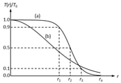
焦点外れ像を改良する従来の方法として、図1の(b)で示されるような径方向の透過率分布がガウス分布型となる透過率分布素子を絞り近傍に配置した撮影レンズ系が知られている。絞り近傍に透過率分布素子を配置することで、焦点外れ像の強度ムラを引き起こす原因となっているサジタルハロを除去することが可能となり、焦点外れ像を好ましく見せることができる。 As a conventional method for improving an out-of-focus image, a photographing lens system in which a transmittance distribution element having a Gaussian transmittance distribution in the radial direction as shown in FIG. 1 (b) is arranged near the aperture is known. ing. By arranging the transmittance distribution element in the vicinity of the aperture, it is possible to remove the sagittal halo that causes the intensity unevenness of the out-of-focus image, and the out-of-focus image can be made to look preferable.
しかしながら、ガウス分布型の透過率分布では、焦点外れ像の強度ムラとは関係のない中心付近を通過する光線に対しても透過率の減少効果を与えてしまい、焦点外れ像の光量の低下とそれに伴う焦点外れ像の大きさの減少が避けられない。 However, in the Gaussian-distributed transmittance distribution, the transmittance is reduced even for light rays passing near the center, which are not related to the intensity unevenness of the out-of-focus image, resulting in a decrease in the amount of light in the out-of-focus image. The accompanying decrease in the size of the out-of-focus image is inevitable.
そこで、本発明は図1の(a)で示されるような透過率分布を有する光学素子を用いることで、光束の中心付近の光量低下を抑制しつつ、焦点外れ像の見え方を改良している。 Therefore, the present invention uses an optical element having a transmittance distribution as shown in FIG. 1A to improve the appearance of an out-of-focus image while suppressing a decrease in the amount of light near the center of the luminous flux. There is.
また、一般的な撮影レンズ系では軸外光束に口径食が見られる。ここで口径食とは光束の一部がケラレることを意味しており、ビネッティングとも呼ばれる。口径食のある撮影レンズ系では、軸上光束と軸外光束で絞りを通過する領域が一致しないために、透過率分布素子によって得られる効果が画角によって異なってしまう。 In addition, vignetting is seen in the off-axis luminous flux in a general photographing lens system. Here, vignetting means that a part of the luminous flux is eclipsed, and is also called vignette. In a photographing lens system with vignetting, the region of the on-axis luminous flux and the off-axis luminous flux passing through the diaphragm do not match, so that the effect obtained by the transmittance distribution element differs depending on the angle of view.
一般には、軸外光束は軸上光束より絞りの狭い範囲を通過するため、軸上光束に合わせた透過率分布とした場合は軸外光束ではその透過率分布の影響を得られない。また、絞りから離れた位置に透過率分布素子を配置した場合は軸外光束の中心が光軸から離れてしまうため、中心対称な透過率分布では軸外光束の透過率が非対称となってしまう。 In general, the off-axis luminous flux passes through a narrower range than the on-axis luminous flux. Therefore, when the transmittance distribution is matched to the on-axis luminous flux, the off-axis luminous flux cannot be affected by the transmittance distribution. In addition, when the transmittance distribution element is placed at a position away from the aperture, the center of the off-axis luminous flux is separated from the optical axis, so that the transmittance of the off-axis luminous flux becomes asymmetric in the center-symmetric transmittance distribution. ..
そこで本発明では、絞りより物体側へ離れた位置と絞りより像側へ離れた位置では軸外光束の形状が上下反転したような関係になることに着目した。絞りの前後に少なくとも1つの透過率分布素子を配置することで、軸外光束の瞳透過率分布を等価的に中心対称に近づけることが可能となる。これにより、軸外画角における焦点外れ像の改良効果を重視する場合は、透過率分布を有する光学素子を絞り前後に配置することで軸外光束に対しても有効にアポダイゼーション効果を得ている。 Therefore, in the present invention, attention has been paid to the relationship that the shape of the off-axis luminous flux is upside down at the position far from the diaphragm to the object side and the position far from the diaphragm to the image side. By arranging at least one transmittance distribution element before and after the diaphragm, it is possible to make the pupil transmittance distribution of the off-axis luminous flux equivalently close to the central symmetry. As a result, when emphasizing the effect of improving the out-of-focus image at the off-axis angle of view, the apodization effect is effectively obtained for the off-axis luminous flux by arranging optical elements having a transmittance distribution before and after the aperture. ..
本発明の撮影レンズ系(光学系)は、絞りと、アポダイゼーション効果を奏する光学素子とを有する。光学素子の透過率は、光軸から径方向に離れるにしたがって減少し、透過率は入射光の波長によって異なる。 The photographing lens system (optical system) of the present invention has a diaphragm and an optical element that exerts an apodization effect. The transmittance of the optical element decreases as the distance from the optical axis increases in the radial direction, and the transmittance varies depending on the wavelength of the incident light.
光学系の有効径をra、光学素子において透過率が最大値の0.9倍の値となる位置の径方向における光軸からの距離をr1、光学素子において透過率が最大値の0.5倍となる位置の径方向における光軸からの距離をr2、光学素子において透過率が最大値の0.1倍となる位置の径方向における光軸からの距離をr3とするとき、
0.6≦r2/ra≦0.9 (1)
0.1≦(r3-r1)/ra (2)
なる条件式を満たすことを特徴とする。
The effective diameter of the optical system is ra, the distance from the optical axis in the radial direction at the position where the transmittance is 0.9 times the maximum value in the optical element is r 1 , and the transmittance is 0 in the optical element. . When the distance from the optical axis in the radial direction at the position where the transmittance is 5 times is r 2 , and the distance from the optical axis in the radial direction at the position where the transmittance is 0.1 times the maximum value in the optical element is r 3 . ,
0.6 ≤ r 2 / ra ≤ 0.9 (1)
0.1 ≤ (r 3 -r 1 ) / ra (2)
It is characterized by satisfying the conditional expression.
周辺部で光量が大きいエッジの効いた焦点外れ像を改良するには、光束の周辺部での透過率を光束の中央部よりも低くする必要がある。この条件を満たさない場合、光束の周辺部での光量が光束の中央部より強まり、よりエッジの効いた汚い焦点外れ像となってしまう。このため、透過率分布素子が有する透過率は周辺部において中心から径方向に離れるに従って減少することが好ましい。 In order to improve the edgy out-of-focus image with a large amount of light in the peripheral part, it is necessary to make the transmittance in the peripheral part of the light flux lower than that in the central part of the light flux. If this condition is not satisfied, the amount of light in the peripheral portion of the light flux becomes stronger than that in the central portion of the light flux, resulting in a more edgy and dirty out-of-focus image. Therefore, it is preferable that the transmittance of the transmittance distribution element decreases in the peripheral portion as the distance from the center increases in the radial direction.
周辺部が色づいた焦点外れ像を改良するには、波長によって径方向の透過率分布の形状を変化させる必要がある。この条件を満たさない場合、例えば赤、緑、青の波長によって焦点外れ像の大きさが異なり、焦点外れ像の輪郭が色づいてしまい焦点外れ像の見え方が悪化する。赤、緑、青のそれぞれの波長域の光だけを吸収する物質を所望の割合で透過率分布素子の吸収物質として用いることで、透過率に分光特性を持たせることができる。さらに、光軸から径方向の距離によって前記吸収物質の割合を変化させることで、波長によって径方向の透過率分布の形状が異なる透過率分布素子を製作することが可能である。また、誘電体や金属の薄膜を用いた多層膜の場合は、多層膜の構成を光軸から径方向の距離で異なるようにすることで、同様に波長によって径方向の透過率分布の形状が異なる透過率分布素子を製作可能である。 In order to improve the out-of-focus image in which the peripheral part is colored, it is necessary to change the shape of the transmittance distribution in the radial direction depending on the wavelength. If this condition is not satisfied, the size of the out-of-focus image differs depending on the wavelengths of red, green, and blue, for example, the outline of the out-of-focus image is colored, and the appearance of the out-of-focus image deteriorates. By using a substance that absorbs only light in each of the red, green, and blue wavelength ranges as an absorbent substance of the transmittance distribution element at a desired ratio, it is possible to give the transmittance a spectral characteristic. Further, by changing the ratio of the absorbent substance depending on the distance from the optical axis in the radial direction, it is possible to manufacture a transmittance distribution element having a different shape of the transmittance distribution in the radial direction depending on the wavelength. Further, in the case of a multilayer film using a thin film of a dielectric or a metal, by making the composition of the multilayer film different depending on the distance in the radial direction from the optical axis, the shape of the transmittance distribution in the radial direction is similarly changed depending on the wavelength. It is possible to manufacture different transmittance distribution elements.
条件式(1)及び(2)は透過率分布素子が有する透過率分布の形状に関する式である。中心から一定の範囲では透過率を落とさないことでレンズ系が取り込む光量を増やすことができる。なお、光束の中央部においては、一定の範囲で透過率が一定であっても構わない。また、エレクトロクロミック材料を用いた透過率分布素子を使用した場合、透過率が滑らかに変化するような分布を作成することは難しく、段階的に透過率を変えてもよい。 The conditional equations (1) and (2) are equations relating to the shape of the transmittance distribution of the transmittance distribution element. The amount of light captured by the lens system can be increased by not reducing the transmittance in a certain range from the center. In the central portion of the luminous flux, the transmittance may be constant within a certain range. Further, when a transmittance distribution element using an electrochromic material is used, it is difficult to create a distribution in which the transmittance changes smoothly, and the transmittance may be changed step by step.
条件式(1)の下限値を下回ると透過率が最大透過率の5割未満となる領域が広くなりすぎる。これにより焦点外れ像の強度ムラを引き起こすサジタルハロ成分以外の光線も除去してしまい、焦点外れ像の光量が低くなりすぎるため好ましくない。条件式(1)の上限値を上回ると透過率が最大透過率の5割未満となる領域が狭くなりすぎる。これにより透過率分布素子による焦点外れ像を改良する効果が低減してしまい、エッジの効いた焦点外れ像となってしまうため好ましくない。 If it is below the lower limit of the conditional expression (1), the region where the transmittance is less than 50% of the maximum transmittance becomes too wide. As a result, light rays other than the sagittal halo component that cause uneven intensity of the out-of-focus image are also removed, and the amount of light of the out-of-focus image becomes too low, which is not preferable. If the upper limit of the conditional expression (1) is exceeded, the region where the transmittance is less than 50% of the maximum transmittance becomes too narrow. As a result, the effect of improving the out-of-focus image by the transmittance distribution element is reduced, and the out-of-focus image with an edge is obtained, which is not preferable.
条件式(2)の下限値を下回ると透過率が最大透過率の9割から1割へ変化する領域の幅が狭くなりすぎる。これにより径方向の透過率分布が急峻に変化することになり、焦点外れ像の輪郭の強度をなだらかに変化させることが難しくなってしまい、焦点外れ像の見え方を改善させる効果が低減してしまうので好ましくない。 If it falls below the lower limit of the conditional expression (2), the width of the region where the transmittance changes from 90% to 10% of the maximum transmittance becomes too narrow. As a result, the transmittance distribution in the radial direction changes sharply, making it difficult to gently change the intensity of the contour of the out-of-focus image, and the effect of improving the appearance of the out-of-focus image is reduced. It is not preferable because it will end up.
本発明の撮影レンズ系は、赤、緑、青の3色の波長に対して、前記分布形状が下記の条件式(3)を満たすことを特徴とする。
r2G/ra<r2R/ra または r2G/ra<r2B/ra (3)
ただし、r2Rを赤色の波長に対する透過率が最大透過率の5割となる距離、r2Gを緑色の波長に対する透過率が最大透過率の5割となる距離、r2Bを青色の波長に対する透過率が最大透過率の5割となる距離とする。つまり、r2Rは光学素子において赤色の波長に対する透過率が最大値の0.5倍の値となる位置の径方向における光軸からの距離、r2Gは光学素子において緑色の波長に対する透過率が最大値の0.5倍の値となる位置の径方向における光軸からの距離、r2Bは光学素子において青色の波長に対する透過率が最大値の0.5倍の値となる位置の径方向における光軸からの距離である。
The photographing lens system of the present invention is characterized in that the distributed shape satisfies the following conditional expression (3) for wavelengths of three colors of red, green, and blue.
r 2G / ra <r 2R / ra or r 2G / ra <r 2B / ra (3)
However, r 2R is the distance where the transmittance for the red wavelength is 50% of the maximum transmittance, r 2G is the distance where the transmittance for the green wavelength is 50% of the maximum transmittance, and r 2B is the transmission for the blue wavelength. The distance is such that the rate is 50% of the maximum transmittance. That is, r 2R is the distance from the optical axis in the radial direction at the position where the transmittance for the red wavelength in the optical element is 0.5 times the maximum value, and r 2G is the transmittance for the green wavelength in the optical element. The distance from the optical axis in the radial direction of the position where the value is 0.5 times the maximum value, r 2B is the radial direction of the position where the transmittance for the blue wavelength in the optical element is 0.5 times the maximum value. Is the distance from the optical axis in.
一般的に、広角から中望遠の撮影レンズ系においては、画像中心部付近の焦点外れ像は輪郭が緑色に色づいてしまう。これは緑色の波長の光線によって形成される焦点外れ像の大きさが赤色や青色に比べ大きくなるためであり、この課題を解決するためには、緑色の波長に対する径方向の透過率分布形状の幅を他の色の波長と比較して狭くする必要がある。 Generally, in a wide-angle to medium-telephoto shooting lens system, the outline of an out-of-focus image near the center of an image is colored green. This is because the size of the out-of-focus image formed by the light beam of the green wavelength is larger than that of red and blue, and in order to solve this problem, the radial transmittance distribution shape with respect to the green wavelength is used. The width needs to be narrower than the wavelengths of other colors.
無限遠にフォーカスした際に、前記撮影レンズ系の焦点距離をf、開放F値をFnoとし、下記の条件式(4)を満たすことが好ましい。
8mm≦f/Fno≦70mm (4)
条件式(4)は撮影レンズの入射瞳径に関する式である。条件式(4)の下限値を下回ると撮像面上での1つ1つの焦点外れ像が占める領域が小さくなりすぎる。このとき焦点外れ像に与える透過率分布が撮像面上であまりにも小さくなるため、透過率分布素子による焦点外れ像を改良する効果が低減する。そもそも焦点外れ像が小さいために汚い焦点外れ像が撮影時に問題となりにくい。条件式(4)の上限値を上回ると焦点外れ像が大きくなり、撮像面上での1つ1つの焦点外れ像が占める領域が大きくなりすぎる。エッジの効いた焦点外れ像は撮影レンズ系の収差に対応して形成されるが、条件式(4)の上限値を上回るような大きい焦点外れ像では収差が焦点外れ像の光量分布に与える影響が小さくなるため、汚い焦点外れ像が撮影時に問題となりにくい。条件式(4)はさらに好ましくは次の(4a)のように設定するのが良い。
10mm≦f/Fno≦65mm (4a)
前記撮影レンズの半画角ωは以下の条件式(5)を満たすことが好ましい。
9°≦ω≦45° (5)
条件式(5)は撮影レンズの半画角に関する式である。エッジの効いた焦点外れ像は撮影レンズ系の収差に対応して形成されるが、条件式(5)の下限値を下回るような撮影レンズ系では焦点外れ像の光量分布を悪化させる収差を設計で抑えやすい。そのため、そもそも汚い焦点外れ像が生じにくく、透過率分布素子の効果が低減する。なお、条件式(5)の下限値を満たす場合は、撮影レンズのパースによる背景圧縮効果のために、背景に小さい点状または細い線状の光源や被写体が生じやすい。このような被写体は焦点外れ像の輪郭が目立ちやすく、透過率分布素子の効果がより有効である。条件式(5)の上限値を上回ると、軸外光束における口径食がひどくなる。このとき軸上光束及び軸外光束に焦点外れ像の改良効果を同時に与えることが困難になるため、好ましくない。
When focused at infinity, it is preferable that the focal length of the photographing lens system is f and the open F value is Fno, and the following conditional expression (4) is satisfied.
8 mm ≤ f / Fno ≤ 70 mm (4)
The conditional expression (4) is an expression relating to the entrance pupil diameter of the photographing lens. If it falls below the lower limit of the conditional expression (4), the area occupied by each out-of-focus image on the imaging surface becomes too small. At this time, the transmittance distribution given to the out-of-focus image becomes too small on the imaging surface, so that the effect of improving the out-of-focus image by the transmittance distribution element is reduced. Since the out-of-focus image is small in the first place, a dirty out-of-focus image is unlikely to be a problem when shooting. If the upper limit of the conditional expression (4) is exceeded, the out-of-focus image becomes large, and the area occupied by each out-of-focus image on the imaging surface becomes too large. An edgy out-of-focus image is formed in response to the aberration of the photographing lens system, but in a large out-of-focus image that exceeds the upper limit of the conditional equation (4), the effect of the aberration on the light amount distribution of the out-of-focus image. Is smaller, so dirty out-of-focus images are less likely to be a problem when shooting. The conditional expression (4) is more preferably set as follows (4a).
10 mm ≤ f / Fno ≤ 65 mm (4a)
It is preferable that the half angle of view ω of the photographing lens satisfies the following conditional expression (5).
9 ° ≤ ω ≤ 45 ° (5)
The conditional expression (5) is an expression relating to the half angle of view of the photographing lens. An edgy out-of-focus image is formed in response to the aberration of the taking lens system, but in a taking lens system that falls below the lower limit of the conditional equation (5), an aberration that deteriorates the light amount distribution of the out-of-focus image is designed. Easy to control. Therefore, a dirty out-of-focus image is unlikely to occur in the first place, and the effect of the transmittance distribution element is reduced. When the lower limit of the conditional expression (5) is satisfied, a small dot-like or thin linear light source or a subject is likely to occur in the background due to the background compression effect of the perspective of the photographing lens. In such a subject, the outline of the out-of-focus image is easily conspicuous, and the effect of the transmittance distribution element is more effective. If the upper limit of the conditional expression (5) is exceeded, vignetting in the off-axis luminous flux becomes severe. At this time, it is difficult to simultaneously give the on-axis luminous flux and the off-axis luminous flux an effect of improving the out-of-focus image, which is not preferable.
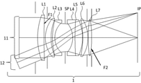
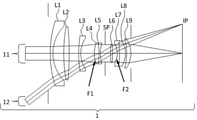
各実施例の撮影レンズ系1は図2、図6、図10、図14に示されている。図中の11は軸上光束、12は最軸外光束に対応している。軸外光束とは光軸外に結像する光束のことであり、その中で撮像面の最端部に結像する光束のことを最軸外光束と呼ぶ。図中では光軸より下側から撮影レンズ系に入射する光束を代表的に示している。Li(iは自然数)はレンズ群、SPは絞り、IPは像面、F1またはF2は透過率分布素子である。
The photographing
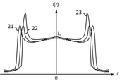
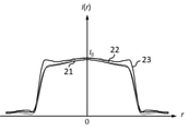
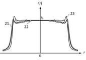
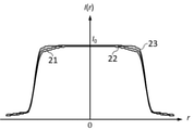
各実施例の撮影レンズ系において透過率分布素子に透過率分布が付与されていない構成での、撮像面に形成される赤、緑、青の波長の焦点外れ像の強度分布は図3、図11、図15に示されている。図中の21は緑色の波長(550nm)の光線の軸上画角における焦点外れ像の強度分布、22は赤色の波長(650 nm)の光線の軸上画角における焦点外れ像の強度分布、23は青色の波長(450 nm)の光線の軸上画角における焦点外れ像の強度分布である。I(r)は位置rでの強度、I0は主光線が撮像面に入射する位置での強度を表している。前記焦点外れ像の強度分布はメリジオナル面に垂直で主光線の入射位置を通る断面において評価した。
The intensity distribution of the out-of-focus images of red, green, and blue wavelengths formed on the imaging surface in the configuration in which the transmittance distribution element is not imparted to the transmittance distribution element in the photographing lens system of each embodiment is shown in FIGS. 11, shown in FIG. In the figure, 21 is the intensity distribution of the out-of-focus image at the on-axis angle of view of the green wavelength (550 nm) ray, and 22 is the intensity distribution of the out-of-focus image at the on-axis angle of view of the red wavelength (650 nm) ray.
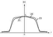
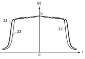
各実施例の撮影レンズ系において透過率分布素子に透過率分布が付与された構成での、撮像面に形成される赤、緑、青の波長の焦点外れ像の強度分布は図5、図9、図13、図17に示されている。 In the photographing lens system of each embodiment, the intensity distributions of the out-of-focus images of the red, green, and blue wavelengths formed on the imaging surface in the configuration in which the transmittance distribution is applied to the transmittance distribution elements are shown in FIGS. 5 and 9. , 13 and 17.
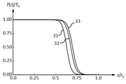
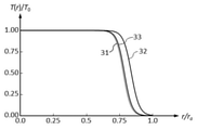
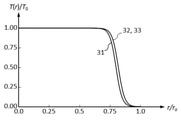
各実施例の透過率分布素子が有する透過率分布は図4、図7、図12、図16に示されている。図中の31は緑色の波長(550nm)に対する透過率分布、32は赤色の波長(650 nm)に対する透過率分布、33は青色の波長(450 nm)に対する透過率分布である。T(r)は位置rでの透過率、T0は最大透過率を表している。 The transmittance distribution of the transmittance distribution element of each embodiment is shown in FIGS. 4, 7, 12, and 16. In the figure, 31 is a transmittance distribution for a green wavelength (550 nm), 32 is a transmittance distribution for a red wavelength (650 nm), and 33 is a transmittance distribution for a blue wavelength (450 nm). T (r) represents the transmittance at the position r, and T 0 represents the maximum transmittance.
次に本発明の各実施例について詳細に説明する。 Next, each embodiment of the present invention will be described in detail.
図2は実施例1の撮影レンズ系の断面図である。絞り位置に透過率分布素子F1が配置されている。この透過率分布素子F1によって、軸上光束11から最軸外光束12までのあらゆる画角の光束に対して瞳強度分布を与え、焦点外れ像の見え方を改善している。
FIG. 2 is a cross-sectional view of the photographing lens system of the first embodiment. The transmittance distribution element F1 is arranged at the aperture position. The transmittance distribution element F1 gives the pupil intensity distribution to the light fluxes of all angles of view from the in-axis
図3は透過率分布素子に透過率分布が付与されていない構成での、撮像面に形成される軸上画角の焦点外れ像の強度分布を示している。実施例1における焦点外れ像は、撮影レンズ系の焦点距離をfとしたとき、撮像面から50f離れた位置に合焦させた状態において撮像面から235f離れた物体の焦点外れ像である。図3から明らかなように緑色の波長の焦点外れ像の大きさが赤色、青色に比べて大きくなっている。また、各波長の強度分布は分布の端で強度が増している。 FIG. 3 shows the intensity distribution of the out-of-focus image of the on-axis angle of view formed on the image pickup surface in the configuration in which the transmittance distribution is not applied to the transmittance distribution element. The out-of-focus image in Example 1 is an out-of-focus image of an object 235 f away from the image pickup surface in a state of being focused at a position 50 f away from the image pickup surface when the focal length of the photographing lens system is f. As is clear from FIG. 3, the size of the out-of-focus image of the green wavelength is larger than that of red and blue. In addition, the intensity distribution of each wavelength increases at the edge of the distribution.
この焦点外れ像の色ムラと強度ムラを改善するため、実施例1の透過率分布素子F1に図4の透過率分布を与えた。 In order to improve the color unevenness and the intensity unevenness of this out-of-focus image, the transmittance distribution of FIG. 4 was given to the transmittance distribution element F1 of Example 1.
図5は透過率分布素子F1に図4の透過率分布が付与された構成での、撮像面に形成される軸上画角の焦点外れ像の強度分布を示している。図5からわかるように強度分布の大きさが各波長で等しくなっており、分布の端での強度も緩やかに減少している。その際、中心付近の強度の低下は起こっていない。 FIG. 5 shows the intensity distribution of the out-of-focus image of the on-axis angle of view formed on the image pickup surface in the configuration in which the transmittance distribution of FIG. 4 is given to the transmittance distribution element F1. As can be seen from FIG. 5, the magnitude of the intensity distribution is the same at each wavelength, and the intensity at the edge of the distribution also gradually decreases. At that time, the strength near the center did not decrease.
よって、実施例1の透過率分布素子F1により、光量の低下を抑制しつつ、周辺部が色づいたエッジの効いた焦点外れ像を周辺部の色づきがなく強度が緩やかに減少する良好な焦点外れ像に改善している。 Therefore, the transmittance distribution element F1 of Example 1 suppresses a decrease in the amount of light, and at the same time, a good out-of-focus image in which the peripheral portion is colored and the intensity of the out-of-focus image with an edge is gradually reduced without coloring in the peripheral portion. It has improved to the image.
図6は実施例2の撮影レンズ系の断面図である。絞りより物体側に透過率分布素子F1が、絞りより像側に透過率分布素子F2が配置されている。その際、軸外光束の瞳透過率分布を等価的に中心対称に近づけるため、軸外光束の形状が中心対称に近い2面に透過率分布素子F1,F2を配置した。前記透過率分布素子は曲率を持ったレンズ面に透過率分布を有する構成とした。前記透過率分布素子F1及びF2によって、軸上光束11から最軸外光束12までのあらゆる画角の光束に対して瞳強度分布を与え、焦点外れ像の見え方を改善している。
FIG. 6 is a cross-sectional view of the photographing lens system of the second embodiment. The transmittance distribution element F1 is arranged on the object side of the aperture, and the transmittance distribution element F2 is arranged on the image side of the aperture. At that time, in order to make the pupil transmittance distribution of the off-axis luminous flux equivalently close to the central symmetry, the transmittance distribution elements F1 and F2 were arranged on two surfaces in which the shape of the off-axis luminous flux was close to the central symmetry. The transmittance distribution element has a transmittance distribution on a lens surface having a curvature. The transmittance distribution elements F1 and F2 provide a pupil intensity distribution to light fluxes having all angles of view from the on-
焦点外れ像の色ムラと強度ムラを改善するため、実施例2の透過率分布素子F1と透過率分布素子F2に図7の透過率分布を与えた。 In order to improve the color unevenness and the intensity unevenness of the out-of-focus image, the transmittance distribution of FIG. 7 was given to the transmittance distribution element F1 and the transmittance distribution element F2 of Example 2.
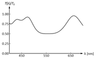
図8は光軸から径方向の距離が有効径raの5割となる位置での前記透過率分布の分光特性を示している。透過率分布素子を、5層構成の多層膜とすることで、径方向の距離が有効径raの5割となる位置にて各波長(λ)の透過率が図7の関係を満足する分光特性を実現できている。 FIG. 8 shows the spectral characteristics of the transmittance distribution at a position where the radial distance from the optical axis is 50% of the effective diameter ra. By forming the transmittance distribution element into a multi-layer film having a five-layer structure, the transmittance of each wavelength (λ) satisfies the relationship shown in FIG. 7 at a position where the radial distance is 50% of the effective diameter ra. The spectral characteristics can be realized.
図9は透過率分布素子F1と透過率分布素子F2に図7の透過率分布が付与された構成での、撮像面に形成される軸上画角の焦点外れ像の強度分布を示している。図9からわかるように強度分布の大きさが各波長で等しくなっており、分布の端での強度も緩やかに減少している。その際、中心付近の強度の低下は起こっていない。 FIG. 9 shows the intensity distribution of the out-of-focus image of the on-axis angle of view formed on the imaging surface in the configuration in which the transmittance distribution element F1 and the transmittance distribution element F2 of FIG. 7 are given the transmittance distribution of FIG. .. As can be seen from FIG. 9, the magnitude of the intensity distribution is the same at each wavelength, and the intensity at the edge of the distribution also gradually decreases. At that time, the strength near the center did not decrease.
よって、実施例2の透過率分布素子F1と透過率分布素子F2により、光量の低下を抑制しつつ、周辺部が色づいたエッジの効いた焦点外れ像を周辺部の色づきがなく強度が緩やかに減少する良好な焦点外れ像に改善している。 Therefore, the transmittance distribution element F1 and the transmittance distribution element F2 of the second embodiment suppress the decrease in the amount of light, and at the same time, the out-of-focus image with the edge colored in the peripheral portion is not colored in the peripheral portion and the intensity is moderately reduced. It is improving to a good out-of-focus image that decreases.
図10は実施例3の撮影レンズ系の断面図である。絞りより像側に透過率分布素子F1が配置されている。この透過率分布素子F1によって、軸上光束11から最軸外光束12までのあらゆる画角の光束に対して瞳強度分布を与え、焦点外れ像の見え方を改善している。
FIG. 10 is a cross-sectional view of the photographing lens system of the third embodiment. The transmittance distribution element F1 is arranged on the image side of the aperture. The transmittance distribution element F1 gives the pupil intensity distribution to the light fluxes of all angles of view from the in-axis
図11は透過率分布素子に透過率分布が付与されていない構成での、撮像面に形成される軸上画角の焦点外れ像の強度分布を示している。実施例3における焦点外れ像は、撮影レンズ系の焦点距離をfとしたとき、撮像面から50f離れた位置に合焦させた状態において撮像面から90f離れた物体の焦点外れ像である。図11から明らかなように緑色と赤色の波長の焦点外れ像の大きさが青色に比べて大きくなっている。また、各波長の強度分布は分布の端で強度が増している。 FIG. 11 shows the intensity distribution of the out-of-focus image of the on-axis angle of view formed on the image pickup surface in the configuration in which the transmittance distribution is not applied to the transmittance distribution element. The out-of-focus image in Example 3 is an out-of-focus image of an object 90 f away from the image pickup surface in a state of being focused at a position 50 f away from the image pickup surface when the focal length of the photographing lens system is f. As is clear from FIG. 11, the size of the out-of-focus image of the wavelengths of green and red is larger than that of blue. In addition, the intensity distribution of each wavelength increases at the edge of the distribution.
この焦点外れ像の色ムラと強度ムラを改善するため、実施例3の透過率分布素子F1に図12の透過率分布を与えた。 In order to improve the color unevenness and the intensity unevenness of this out-of-focus image, the transmittance distribution of FIG. 12 was given to the transmittance distribution element F1 of Example 3.
図13は透過率分布素子F1に図12の透過率分布が付与された構成での、撮像面に形成される軸上画角の焦点外れ像の強度分布を示している。図13からわかるように強度分布の大きさが各波長で等しくなっており、分布の端での強度も緩やかに減少している。その際、中心付近の強度の低下は起こっていない。 FIG. 13 shows the intensity distribution of the out-of-focus image of the on-axis angle of view formed on the image pickup surface in the configuration in which the transmittance distribution of FIG. 12 is given to the transmittance distribution element F1. As can be seen from FIG. 13, the magnitude of the intensity distribution is the same at each wavelength, and the intensity at the edge of the distribution also gradually decreases. At that time, the strength near the center did not decrease.
よって、実施例3の透過率分布素子F1により、光量の低下を抑制しつつ、周辺部が色づいたエッジの効いた焦点外れ像を周辺部の色づきがなく強度が緩やかに減少する良好な焦点外れ像に改善している。 Therefore, the transmittance distribution element F1 of Example 3 suppresses a decrease in the amount of light, and at the same time, a good out-of-focus image in which the peripheral portion is colored and the intensity of the out-of-focus image with an edge is gradually reduced without coloring in the peripheral portion. It has improved to the image.
図14は実施例4の撮影レンズ系の断面図である。絞りより物体側に透過率分布素子F1が、絞りより像側に透過率分布素子F2が配置されている。その際、軸外光束の瞳透過率分布を等価的に中心対称に近づけるため、軸外光束の形状が中心対称に近い2面に配置した。前記透過率分布素子は曲率を持ったレンズ面に透過率分布を有する構成とした。前記透過率分布素子F1及びF2によって、軸上光束11から最軸外光束12までのあらゆる画角の光束に対して瞳強度分布を与え、焦点外れ像の見え方を改善している。
FIG. 14 is a cross-sectional view of the photographing lens system of the fourth embodiment. The transmittance distribution element F1 is arranged on the object side of the aperture, and the transmittance distribution element F2 is arranged on the image side of the aperture. At that time, in order to make the pupil transmittance distribution of the off-axis luminous flux equivalently close to the central symmetry, the shape of the off-axis luminous flux was arranged on two surfaces close to the central symmetry. The transmittance distribution element has a transmittance distribution on a lens surface having a curvature. The transmittance distribution elements F1 and F2 provide a pupil intensity distribution to light fluxes having all angles of view from the on-
図15は透過率分布素子に透過率分布が付与されていない構成での、撮像面に形成される軸上画角の焦点外れ像の強度分布を示している。実施例4における焦点外れ像は、撮影レンズ系の焦点距離をfとしたとき、撮像面から16f離れた位置に合焦させた状態において撮像面から無限遠離れた物体の焦点外れ像である。図15から明らかなように緑色の波長の焦点外れ像の大きさが赤色、青色に比べて大きくなっている。また、各波長の強度分布は分布の端で強度が増している。 FIG. 15 shows the intensity distribution of the out-of-focus image of the on-axis angle of view formed on the image pickup surface in the configuration in which the transmittance distribution is not applied to the transmittance distribution element. The out-of-focus image in Example 4 is an out-of-focus image of an object far away from the image pickup surface in a state of being focused at a position 16 f away from the image pickup surface when the focal length of the photographing lens system is f. As is clear from FIG. 15, the size of the out-of-focus image of the green wavelength is larger than that of red and blue. In addition, the intensity distribution of each wavelength increases at the edge of the distribution.
この焦点外れ像の色ムラと強度ムラを改善するため、実施例4の透過率分布素子F1と透過率分布素子F2に図16の透過率分布を与えた。 In order to improve the color unevenness and the intensity unevenness of this out-of-focus image, the transmittance distribution of FIG. 16 was given to the transmittance distribution element F1 and the transmittance distribution element F2 of Example 4.
図17は透過率分布素子F1と透過率分布素子F2に図16の透過率分布が付与された構成での、撮像面に形成される軸上画角の焦点外れ像の強度分布を示している。図17からわかるように強度分布の大きさが各波長で等しくなっており、分布の端での強度も緩やかに減少している。その際、中心付近の強度の低下は起こっていない。 FIG. 17 shows the intensity distribution of the out-of-focus image of the on-axis angle of view formed on the imaging surface in the configuration in which the transmittance distribution element F1 and the transmittance distribution element F2 of FIG. 16 are given the transmittance distribution of FIG. .. As can be seen from FIG. 17, the magnitude of the intensity distribution is the same at each wavelength, and the intensity at the edge of the distribution also gradually decreases. At that time, the strength near the center did not decrease.
よって、実施例4の透過率分布素子F1と透過率分布素子F2により、光量の低下を抑制しつつ、周辺部が色づいたエッジの効いた焦点外れ像を周辺部の色づきがなく強度が緩やかに減少する良好な焦点外れ像に改善している。 Therefore, the transmittance distribution element F1 and the transmittance distribution element F2 of the fourth embodiment suppress the decrease in the amount of light, and at the same time, the out-of-focus image with the edge colored in the peripheral portion is not colored in the peripheral portion and the intensity is moderately reduced. It is improving to a good out-of-focus image that decreases.
上記の各実施例では、赤、緑、青の波長として650、550、450 nmの波長を用いて説明したが、同様の考え方を他の波長の組合せ(例えば、656.3、587.6、486.1、435.8の組合せなど)にも適用可能である。 In each of the above examples, the wavelengths of 650, 550, and 450 nm have been described as the wavelengths of red, green, and blue, but the same idea is applied to other combinations of wavelengths (for example, 656.3, 587.6, etc.). It is also applicable to the combination of 486.1 and 435.8, etc.).
以下に本発明の実施例1乃至4に対応する数値実施例1乃至4を示す。各数値実施例において、rは物体側より第i番目の面の曲率半径(mm)、dは物体側より第i番目と第i+1番目の軸上の面間隔(mm)、ndとvdは第i番目の光学部材の屈折率とアッベ数である。焦点距離f(mm)、FナンバーFno、画角ω(度)はそれぞれ無限遠物体に焦点を合わせた時の値である。BFはバックフォーカスであり、レンズ全長は第1面から像面までの距離を表す。また、非球面は面番号の後に、*の符号を付加して表している。非球面形状は、Xを光軸方向の面頂点からの変異量、hを光軸と垂直な方向の光軸からの高さ、rを近軸曲率半径、Kを円錐定数、A4、A6、A8、A10を各々非球面係数としたとき、 The numerical examples 1 to 4 corresponding to Examples 1 to 4 of this invention are shown below. In each numerical example, r is the radius of curvature (mm) of the i-th surface from the object side, d is the surface distance (mm) on the i-th and i + 1th axes from the object side, and nd and vd are the first. The refractive index and Abbe number of the i-th optical member. The focal length f (mm), F number Fno, and angle of view ω (degrees) are values when the object is focused at infinity. BF is the back focus, and the total length of the lens represents the distance from the first surface to the image surface. Further, the aspherical surface is represented by adding a sign of * after the surface number. For the aspherical shape, X is the amount of variation from the surface apex in the optical axis direction, h is the height from the optical axis in the direction perpendicular to the optical axis, r is the paraxial radius of curvature, K is the conical constant, A4, A6, When A8 and A10 are paraxial coefficients, respectively,

なる式で表している。また、「e±Z」の表示は「10±Z」を意味する。
[数値実施例1]
単位 mm
面データ
面番号 r d nd vd 有効径
1 ∞ 2.00 42.78
2 57.520 5.50 1.77250 49.6 38.04
3 395.282 2.80 36.09
4 ∞ -1.60 33.81
5 25.921 5.00 1.83481 42.7 31.97
6 43.002 1.20 29.70
7 59.016 2.00 1.64769 33.8 29.56
8 17.697 9.00 25.24
9(絞り) ∞ 0.00 24.55
10 ∞ 0.50 1.51633 64.1 24.55
11 ∞ 6.00 24.55
12 -19.448 2.00 1.80518 25.4 24.15
13 280.464 6.50 1.75700 47.8 28.14
14 -37.481 0.20 29.83
15 -74.530 4.50 1.88300 40.8 30.67
16 -30.712 -0.80 31.22
17 ∞ 1.00 30.14
18 124.396 3.00 1.80400 46.6 29.66
19 -111.454 0.00 30.02
20 ∞ 0.00 30.32
21 ∞ (可変) 30.32
像面 ∞
各種データ
ズーム比 1.00
焦点距離 52.43
Fナンバー 1.49
画角 22.42
像高 21.64
レンズ全長 88.51
BF 39.71
d21 39.71
入射瞳位置 30.97
射出瞳位置 -33.10
前側主点位置 45.65
後側主点位置 -12.71
ズームレンズ群データ
群 始面 焦点距離 レンズ構成長 前側主点位置 後側主点位置
1 1 52.43 48.80 45.65 -12.71
単レンズデータ
レンズ 始面 焦点距離
1 1 86.53
2 5 68.99
3 7 -39.78
4 10 0.00
5 12 -22.52
6 13 44.06
7 15 56.44
8 18 73.53
[数値実施例2]
単位 mm
面データ
面番号 r d nd vd 有効径
1 ∞ 2.00 42.78
2 57.520 5.50 1.77250 49.6 38.04
3 395.282 2.80 36.09
4 ∞ -1.60 33.81
5 25.921 5.00 1.83481 42.7 31.97
6 43.002 1.20 29.70
7 59.016 2.00 1.64769 33.8 29.56
8 17.697 9.00 25.24
9(絞り) ∞ 6.50 24.55
10 -19.448 2.00 1.80518 25.4 24.15
11 280.464 6.50 1.75700 47.8 28.14
12 -37.481 0.20 29.83
13 -74.530 4.50 1.88300 40.8 30.67
14 -30.712 -0.80 31.22
15 ∞ 1.00 30.14
16 124.396 3.00 1.80400 46.6 29.66
17 -111.454 0.00 30.02
18 ∞ 0.00 30.32
19 ∞ (可変) 30.32
像面 ∞
各種データ
ズーム比 1.00
焦点距離 52.50
Fナンバー 1.49
画角 22.40
像高 21.64
レンズ全長 88.49
BF 39.69
d19 39.69
入射瞳位置 30.97
射出瞳位置 -33.78
前側主点位置 45.96
後側主点位置 -12.81
ズームレンズ群データ
群 始面 焦点距離 レンズ構成長 前側主点位置 後側主点位置
1 1 52.50 48.80 45.96 -12.81
単レンズデータ
レンズ 始面 焦点距離
1 1 86.53
2 5 68.99
3 7 -39.78
4 10 -22.52
5 11 44.06
6 13 56.44
7 16 73.53
[数値実施例3]
単位 mm
面データ
面番号 r d nd vd 有効径
1 106.149 9.00 1.48749 70.2 67.53
2 -290.997 0.50 66.86
3 51.244 9.50 1.49700 81.5 59.18
4 231.499 3.00 57.79
5 -630.036 3.50 1.83400 37.2 57.25
6 93.250 2.50 53.57
7 60.005 8.00 1.49700 81.5 52.05
8 -624.746 0.50 51.23
9 29.265 3.20 1.71736 29.5 42.22
10 24.308 12.50 37.88
11(絞り) ∞ (可変) 35.40
12 -2278.322 4.50 1.84666 23.9 33.80
13 -55.787 2.00 1.72000 50.2 33.04
14 41.821 4.00 29.79
15 ∞ 0.50 1.51633 64.1 29.50
16 ∞ 0.00 29.42
17 ∞ (可変) 29.42
18 -30.566 2.50 1.74077 27.8 25.98
19 196.247 8.50 1.77250 49.6 28.59
20 -39.608 0.50 31.93
21 106.631 6.00 1.83400 37.2 35.15
22 -195.173 (可変) 35.74
像面 ∞
各種データ
ズーム比 1.00
焦点距離 133.12
Fナンバー 2.06
画角 9.23
像高 21.64
レンズ全長 154.90
BF 54.23
d11 2.28
d17 17.69
d22 54.23
入射瞳位置 74.83
射出瞳位置 -89.01
前側主点位置 84.24
後側主点位置 -78.89
ズームレンズ群データ
群 始面 焦点距離 レンズ構成長 前側主点位置 後側主点位置
1 1 93.89 52.20 -8.11 -44.04
2 12 -65.39 11.00 3.68 -4.24
3 18 82.08 17.50 17.56 10.42
単レンズデータ
レンズ 始面 焦点距離
1 1 160.74
2 3 130.14
3 5 -97.18
4 7 110.58
5 9 -273.90
6 12 67.48
7 13 -32.92
8 15 0.00
9 18 -35.53
10 19 43.34
11 21 83.44
[数値実施例4]
単位 mm
面データ
面番号 r d nd vd 有効径
1 ∞ 1.50 54.03
2 79.773 2.00 1.60311 60.6 46.37
3 28.865 8.00 39.23
4 117.212 4.00 1.77250 49.6 37.77
5 -212.879 (可変) 36.80
6 84.814 1.50 1.48749 70.2 24.71
7 19.679 10.00 21.16
8 22.595 3.50 1.91082 35.3 14.46
9 -45.147 1.00 1.73800 32.3 13.37
10 26.917 3.50 12.87
11(絞り) ∞ (可変) 12.80
12 111.141 1.50 1.72916 54.7 12.69
13 -73.101 (可変) 12.63
14 -13.184 1.50 1.74000 28.3 12.65
15 -132.829 4.50 1.69680 55.5 15.15
16 -17.844 0.80 17.62
17* -53.671 3.20 1.58313 59.4 19.54
18 -18.948 0.00 20.58
19 ∞ (可変) 22.26
像面 ∞
非球面データ
第17面
K = 0.00000e+000 A 4=-2.50000e-005 A 6= 4.20000e-008 A 8=-6.00000e-010 A10= 2.00000e-012
各種データ
ズーム比 1.00
焦点距離 28.50
Fナンバー 2.85
画角 37.20
像高 21.64
レンズ全長 99.00
BF 38.00
d 5 7.00
d11 4.00
d13 3.50
d19 38.00
入射瞳位置 28.63
射出瞳位置 -29.20
前側主点位置 45.04
後側主点位置 9.50
ズームレンズ群データ
群 始面 焦点距離 レンズ構成長 前側主点位置 後側主点位置
1 1 -528.68 15.50 -39.98 -57.63
2 6 374.88 19.50 48.86 38.18
3 12 60.69 1.50 0.53 -0.35
4 14 61.47 10.00 17.07 15.27
単レンズデータ
レンズ 始面 焦点距離
1 1 -76.12
2 4 98.37
3 6 -52.96
4 8 16.95
5 9 -22.72
6 12 60.69
7 14 -19.88
8 15 29.12
9 17 48.58
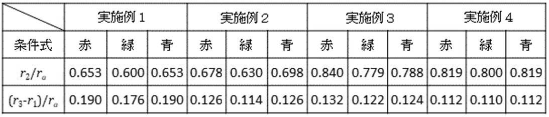
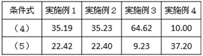
以下の表1及び2に数値実施例1~4の透過率分布素子に付与した透過率分布形状に対する各条件式の数値を示す。なお、表2における条件式(5)の数値の単位は度(°)である。
It is expressed by the formula. Further, the display of "e ± Z" means "10 ± Z ".
[Numerical Example 1]
Unit mm
Surface data Surface number rd nd vd Effective diameter
1 ∞ 2.00 42.78
2 57.520 5.50 1.77250 49.6 38.04
3 395.282 2.80 36.09
4 ∞ -1.60 33.81
5 25.921 5.00 1.83481 42.7 31.97
6 43.002 1.20 29.70
7 59.016 2.00 1.64769 33.8 29.56
8 17.697 9.00 25.24
9 (Aperture) ∞ 0.00 24.55
10 ∞ 0.50 1.51633 64.1 24.55
11 ∞ 6.00 24.55
12 -19.448 2.00 1.80518 25.4 24.15
13 280.464 6.50 1.75700 47.8 28.14
14 -37.481 0.20 29.83
15 -74.530 4.50 1.88300 40.8 30.67
16 -30.712 -0.80 31.22
17 ∞ 1.00 30.14
18 124.396 3.00 1.80400 46.6 29.66
19 -111.454 0.00 30.02
20 ∞ 0.00 30.32
21 ∞ (variable) 30.32
Image plane ∞
Various data Zoom ratio 1.00
Focal length 52.43
F number 1.49
Angle of view 22.42
Image height 21.64
Lens total length 88.51
BF 39.71
d21 39.71
Entrance pupil position 30.97
Exit pupil position -33.10
Front principal point position 45.65
Rear principal point position -12.71
Zoom lens group Data group Start surface Focal length Lens configuration length Front principal point position Posterior principal point position
1 1 52.43 48.80 45.65 -12.71
Single lens data lens Start surface focal length
1 1 86.53
2 5 68.99
3 7 -39.78
4 10 0.00
5 12 -22.52
6 13 44.06
7 15 56.44
8 18 73.53
[Numerical Example 2]
Unit mm
Surface data Surface number rd nd vd Effective diameter
1 ∞ 2.00 42.78
2 57.520 5.50 1.77250 49.6 38.04
3 395.282 2.80 36.09
4 ∞ -1.60 33.81
5 25.921 5.00 1.83481 42.7 31.97
6 43.002 1.20 29.70
7 59.016 2.00 1.64769 33.8 29.56
8 17.697 9.00 25.24
9 (Aperture) ∞ 6.50 24.55
10 -19.448 2.00 1.80518 25.4 24.15
11 280.464 6.50 1.75700 47.8 28.14
12 -37.481 0.20 29.83
13 -74.530 4.50 1.88300 40.8 30.67
14 -30.712 -0.80 31.22
15 ∞ 1.00 30.14
16 124.396 3.00 1.80400 46.6 29.66
17 -111.454 0.00 30.02
18 ∞ 0.00 30.32
19 ∞ (variable) 30.32
Image plane ∞
Various data Zoom ratio 1.00
Focal length 52.50
F number 1.49
Angle of view 22.40
Image height 21.64
Lens total length 88.49
BF 39.69
d19 39.69
Entrance pupil position 30.97
Exit pupil position -33.78
Front principal point position 45.96
Rear principal point position -12.81
Zoom lens group Data group Start surface Focal length Lens configuration length Front principal point position Posterior principal point position
1 1 52.50 48.80 45.96 -12.81
Single lens data lens Start surface focal length
1 1 86.53
2 5 68.99
3 7 -39.78
4 10 -22.52
5 11 44.06
6 13 56.44
7 16 73.53
[Numerical Example 3]
Unit mm
Surface data Surface number rd nd vd Effective diameter
1 106.149 9.00 1.48749 70.2 67.53
2 -290.997 0.50 66.86
3 51.244 9.50 1.49700 81.5 59.18
4 231.499 3.00 57.79
5 -630.036 3.50 1.83400 37.2 57.25
6 93.250 2.50 53.57
7 60.005 8.00 1.49700 81.5 52.05
8-624.746 0.50 51.23
9 29.265 3.20 1.71736 29.5 42.22
10 24.308 12.50 37.88
11 (Aperture) ∞ (Variable) 35.40
12 -2278.322 4.50 1.84666 23.9 33.80
13 -55.787 2.00 1.72000 50.2 33.04
14 41.821 4.00 29.79
15 ∞ 0.50 1.51633 64.1 29.50
16 ∞ 0.00 29.42
17 ∞ (variable) 29.42
18 -30.566 2.50 1.74077 27.8 25.98
19 196.247 8.50 1.77250 49.6 28.59
20 -39.608 0.50 31.93
21 106.631 6.00 1.83400 37.2 35.15
22 -195.173 (variable) 35.74
Image plane ∞
Various data Zoom ratio 1.00
Focal length 133.12
F number 2.06
Angle of view 9.23
Image height 21.64
Lens total length 154.90
BF 54.23
d11 2.28
d17 17.69
d22 54.23
Entrance pupil position 74.83
Exit pupil position -89.01
Front principal point position 84.24
Rear principal point position -78.89
Zoom lens group Data group Start surface Focal length Lens configuration length Front principal point position Posterior principal point position
1 1 93.89 52.20 -8.11 -44.04
2 12 -65.39 11.00 3.68 -4.24
3 18 82.08 17.50 17.56 10.42
Single lens data lens Start surface focal length
1 1 160.74
2 3 130.14
3 5 -97.18
4 7 110.58
5 9 -273.90
6 12 67.48
7 13 -32.92
8 15 0.00
9 18 -35.53
10 19 43.34
11 21 83.44
[Numerical Example 4]
Unit mm
Surface data Surface number rd nd vd Effective diameter
1 ∞ 1.50 54.03
2 79.773 2.00 1.60311 60.6 46.37
3 28.865 8.00 39.23
4 117.212 4.00 1.77250 49.6 37.77
5 -212.879 (variable) 36.80
6 84.814 1.50 1.48749 70.2 24.71
7 19.679 10.00 21.16
8 22.595 3.50 1.91082 35.3 14.46
9 -45.147 1.00 1.73800 32.3 13.37
10 26.917 3.50 12.87
11 (Aperture) ∞ (Variable) 12.80
12 111.141 1.50 1.72916 54.7 12.69
13 -73.101 (variable) 12.63
14 -13.184 1.50 1.74000 28.3 12.65
15 -132.829 4.50 1.69680 55.5 15.15
16 -17.844 0.80 17.62
17 * -53.671 3.20 1.58313 59.4 19.54
18 -18.948 0.00 20.58
19 ∞ (variable) 22.26
Image plane ∞
17th surface of aspherical data
K = 0.00000e + 000 A 4 = -2.50000e-005 A 6 = 4.20000e-008 A 8 = -6.0000e-010 A10 = 2.00000e-012
Various data Zoom ratio 1.00
Focal length 28.50
F number 2.85
Angle of view 37.20
Image height 21.64
Lens total length 99.00
BF 38.00
d 5 7.00
d11 4.00
d13 3.50
d19 38.00
Entrance pupil position 28.63
Exit pupil position -29.20
Front principal point position 45.04
Rear principal point position 9.50
Zoom lens group Data group Start surface Focal length Lens configuration length Front principal point position Posterior principal point position
1 1 -528.68 15.50 -39.98 -57.63
2 6 374.88 19.50 48.86 38.18
3 12 60.69 1.50 0.53 -0.35
4 14 61.47 10.00 17.07 15.27
Single lens data lens Start surface focal length
1 1 -76.12
2 4 98.37
3 6 -52.96
4 8 16.95
5 9-22.72
6 12 60.69
7 14 -19.88
8 15 29.12
9 17 48.58
Tables 1 and 2 below show the numerical values of each conditional expression for the transmittance distribution shape given to the transmittance distribution elements of Examples 1 to 4. The unit of the numerical value of the conditional expression (5) in Table 2 is degree (°).
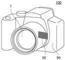
最後に本発明の撮像装置の実施例について述べる。図18は、本実施例の撮像装置(デジタルスチルカメラ)100の概略図である。撮像装置100は、カメラ本体90と、上述した実施例の撮影レンズ(光学系)1と、撮影レンズ1によって形成される像を光電変換する受光素子(撮像素子)92を備える。
Finally, an embodiment of the image pickup apparatus of the present invention will be described. FIG. 18 is a schematic view of the image pickup apparatus (digital still camera) 100 of this embodiment. The
本実施形態の撮像装置100は、高い光学性能を有する撮影レンズ1によって形成された高品位な画像を得ることができる。
The
なお、受光素子92としては、CCDセンサやCMOSセンサ等の撮像素子を用いることができる。このとき、受光素子92により取得された画像の歪曲収差や色収差等の諸収差を電気的に補正することにより、出力画像を高画質化することもできる。
As the
なお、上述した各実施例の撮影レンズは、図18に示したデジタルスチルカメラに限らず、銀塩フィルム用カメラやビデオカメラ、望遠鏡等の種々の光学機器に適用することができる。 The photographing lens of each of the above-described embodiments can be applied not only to the digital still camera shown in FIG. 18 but also to various optical devices such as a silver salt film camera, a video camera, and a telescope.
以上、本発明の好ましい実施形態について説明したが、本発明はこれらの実施形態に限定されず、その要旨の範囲内で種々の変形及び変更が可能である。 Although the preferred embodiments of the present invention have been described above, the present invention is not limited to these embodiments, and various modifications and modifications can be made within the scope of the gist thereof.
SP 絞り、
F1、F2 透過率分布素子、
SP aperture,
F1, F2 transmittance distribution element,
Claims (9)
前記第1の領域における透過率の変化のしかたは、入射光の波長によって異なり、
前記光学素子の有効径をra、前記第1の領域において、透過率が最大値の0.9倍の値となる位置の径方向における前記光軸からの距離をr1、透過率が最大値の0.5倍となる位置の径方向における前記光軸からの距離をr2、透過率が最大値の0.1倍となる位置の径方向における前記光軸からの距離をr3とするとき、波長650nm、波長550nm、及び波長450nmの夫々に対して
0.6≦r2/ra≦0.9
0.1≦(r3-r1)/ra
なる条件式を満たし、
前記第1の領域において、波長650nmに対する透過率が最大値の0.5倍の値となる位置の径方向における前記光軸からの距離をr 2R 、波長550nmに対する透過率が最大値の0.5倍の値となる位置の径方向における前記光軸からの距離をr 2G 、波長450nmに対する透過率が最大値の0.5倍の値となる位置の径方向における前記光軸からの距離をr 2B とするとき、
r 2G /r a <r 2R /r a
r 2G /r a <r 2B /r a
なる条件式の何れかを満たすことを特徴とする光学系。 An optical system having an optical element including a first region in which the transmittance decreases as the distance from the optical axis increases in the radial direction.
How the transmittance changes in the first region depends on the wavelength of the incident light.
The effective diameter of the optical element is ra, the distance from the optical axis in the radial direction at the position where the transmittance is 0.9 times the maximum value in the first region is r 1 , and the transmittance is maximum. The distance from the optical axis in the radial direction at the position where the transmittance is 0.5 times the value is r 2 , and the distance from the optical axis in the radial direction at the position where the transmittance is 0.1 times the maximum value is r 3 . 0.6 ≤ r 2 / ra ≤ 0.9 for each of the wavelengths of 650 nm, 550 nm, and 450 nm.
0.1 ≤ (r 3 -r 1 ) / ra
Satisfy the conditional expression
In the first region, the distance from the optical axis in the radial direction at the position where the transmittance for a wavelength of 650 nm is 0.5 times the maximum value is r 2R , and the transmittance for a wavelength of 550 nm is 0. The distance from the optical axis in the radial direction of the position where the value is 5 times is r 2G , and the distance from the optical axis in the radial direction of the position where the transmittance for the wavelength 450 nm is 0.5 times the maximum value. When using r 2B
r 2G / ra < r 2R / ra
r 2G / ra < r 2B / ra
An optical system characterized by satisfying any of the conditional expressions .
8mm≦f/Fno≦70mm
なる条件式を満たすことを特徴とする請求項1乃至3の何れか一項に記載の光学系。 When the focal length of the optical system is f and the open F value is Fno when focusing at infinity,
8mm ≤ f / Fno ≤ 70mm
The optical system according to any one of claims 1 to 3 , wherein the optical system satisfies the conditional expression.
10mm≦f/Fno≦65mm
なる条件式を満たすことを特徴とする請求項1乃至4の何れか一項に記載の光学系。 When the focal length of the optical system is f and the open F value is Fno when focusing at infinity,
10 mm ≤ f / Fno ≤ 65 mm
The optical system according to any one of claims 1 to 4 , wherein the optical system satisfies the conditional expression.
9°≦ω≦45°
なる条件式を満たすことを特徴とする請求項1乃至5の何れか一項に記載の光学系。 When the half angle of view of the optical system is ω,
9 ° ≤ ω ≤ 45 °
The optical system according to any one of claims 1 to 5 , wherein the optical system satisfies the conditional expression.
Priority Applications (1)
| Application Number | Priority Date | Filing Date | Title |
|---|---|---|---|
| JP2017180873A JP6991808B2 (en) | 2017-09-21 | 2017-09-21 | Optical system and image pickup device |
Applications Claiming Priority (1)
| Application Number | Priority Date | Filing Date | Title |
|---|---|---|---|
| JP2017180873A JP6991808B2 (en) | 2017-09-21 | 2017-09-21 | Optical system and image pickup device |
Publications (3)
| Publication Number | Publication Date |
|---|---|
| JP2019056780A JP2019056780A (en) | 2019-04-11 |
| JP2019056780A5 JP2019056780A5 (en) | 2020-11-12 |
| JP6991808B2 true JP6991808B2 (en) | 2022-02-03 |
Family
ID=66106370
Family Applications (1)
| Application Number | Title | Priority Date | Filing Date |
|---|---|---|---|
| JP2017180873A Expired - Fee Related JP6991808B2 (en) | 2017-09-21 | 2017-09-21 | Optical system and image pickup device |
Country Status (1)
| Country | Link |
|---|---|
| JP (1) | JP6991808B2 (en) |
Families Citing this family (3)
| Publication number | Priority date | Publication date | Assignee | Title |
|---|---|---|---|---|
| CN111239983B (en) * | 2020-03-24 | 2022-06-14 | 南京理工大学 | Wide-angle photographic lens with high imaging quality |
| CN117250736B (en) * | 2023-11-17 | 2024-01-26 | 南京信息工程大学 | Large-image-surface high-resolution wide-spectrum star sensor optical system |
| CN119045268B (en) * | 2024-10-18 | 2025-10-17 | 峰米(重庆)创新科技有限公司 | Illumination system and projection apparatus |
Citations (1)
| Publication number | Priority date | Publication date | Assignee | Title |
|---|---|---|---|---|
| JP2016145862A (en) | 2015-02-06 | 2016-08-12 | キヤノン株式会社 | Optical system and optical device |
-
2017
- 2017-09-21 JP JP2017180873A patent/JP6991808B2/en not_active Expired - Fee Related
Patent Citations (1)
| Publication number | Priority date | Publication date | Assignee | Title |
|---|---|---|---|---|
| JP2016145862A (en) | 2015-02-06 | 2016-08-12 | キヤノン株式会社 | Optical system and optical device |
Also Published As
| Publication number | Publication date |
|---|---|
| JP2019056780A (en) | 2019-04-11 |
Similar Documents
| Publication | Publication Date | Title |
|---|---|---|
| JP6489857B2 (en) | Optical system and optical equipment | |
| JP6849350B2 (en) | Optical system and optical equipment with it | |
| JP4294299B2 (en) | Zoom lens and electronic imaging apparatus using the same | |
| JP3920655B2 (en) | Zoom lens and imaging apparatus using the same | |
| WO2016021228A1 (en) | Image-forming optical system and optical device provided with same | |
| CN111751965B (en) | Zoom lens and imaging apparatus having the same | |
| US20160341973A1 (en) | Image pickup optical system and image pickup apparatus | |
| JP6404795B2 (en) | Zoom lens and imaging device | |
| JP2006162829A (en) | Wide-angle imaging lens and imaging apparatus | |
| CN118732231B (en) | Optical lens | |
| JP7030536B2 (en) | Imaging optical system and imaging device | |
| JP4917922B2 (en) | Zoom lens system, imaging device and camera | |
| JP2006010895A (en) | Three-group zoom lens | |
| JP5921287B2 (en) | Imaging device | |
| WO2016194110A1 (en) | Single-focus optical system and optical device provided with same | |
| JP2004004533A (en) | Zoom lens and electronic imaging apparatus using the same | |
| JP6991808B2 (en) | Optical system and image pickup device | |
| JP6742807B2 (en) | Photographing optical system and imaging device | |
| JP2019200248A (en) | Optical system and imaging device using the same | |
| JP6821365B2 (en) | Optical system and optical equipment with it | |
| JP7515321B2 (en) | Optical system and imaging device | |
| JP2012047869A (en) | Rear converter lens and imaging optical system having the same | |
| JP4007789B2 (en) | Electronic imaging device | |
| JP7443046B2 (en) | Zoom lens and imaging device with it | |
| JP4817551B2 (en) | Zoom lens |
Legal Events
| Date | Code | Title | Description |
|---|---|---|---|
| A521 | Request for written amendment filed |
Free format text: JAPANESE INTERMEDIATE CODE: A523 Effective date: 20200911 |
|
| A621 | Written request for application examination |
Free format text: JAPANESE INTERMEDIATE CODE: A621 Effective date: 20200911 |
|
| A977 | Report on retrieval |
Free format text: JAPANESE INTERMEDIATE CODE: A971007 Effective date: 20210616 |
|
| A131 | Notification of reasons for refusal |
Free format text: JAPANESE INTERMEDIATE CODE: A131 Effective date: 20210629 |
|
| A521 | Request for written amendment filed |
Free format text: JAPANESE INTERMEDIATE CODE: A523 Effective date: 20210819 |
|
| TRDD | Decision of grant or rejection written | ||
| A01 | Written decision to grant a patent or to grant a registration (utility model) |
Free format text: JAPANESE INTERMEDIATE CODE: A01 Effective date: 20211109 |
|
| A61 | First payment of annual fees (during grant procedure) |
Free format text: JAPANESE INTERMEDIATE CODE: A61 Effective date: 20211208 |
|
| R151 | Written notification of patent or utility model registration |
Ref document number: 6991808 Country of ref document: JP Free format text: JAPANESE INTERMEDIATE CODE: R151 |
|
| LAPS | Cancellation because of no payment of annual fees |