WO2016021228A1 - Image-forming optical system and optical device provided with same - Google Patents
Image-forming optical system and optical device provided with same Download PDFInfo
- Publication number
- WO2016021228A1 WO2016021228A1 PCT/JP2015/059055 JP2015059055W WO2016021228A1 WO 2016021228 A1 WO2016021228 A1 WO 2016021228A1 JP 2015059055 W JP2015059055 W JP 2015059055W WO 2016021228 A1 WO2016021228 A1 WO 2016021228A1
- Authority
- WO
- WIPO (PCT)
- Prior art keywords
- lens
- optical system
- imaging optical
- lens group
- positive
- Prior art date
Links
Images


Classifications
-
- G—PHYSICS
- G02—OPTICS
- G02B—OPTICAL ELEMENTS, SYSTEMS OR APPARATUS
- G02B13/00—Optical objectives specially designed for the purposes specified below
- G02B13/18—Optical objectives specially designed for the purposes specified below with lenses having one or more non-spherical faces, e.g. for reducing geometrical aberration
-
- G—PHYSICS
- G02—OPTICS
- G02B—OPTICAL ELEMENTS, SYSTEMS OR APPARATUS
- G02B9/00—Optical objectives characterised both by the number of the components and their arrangements according to their sign, i.e. + or -
- G02B9/64—Optical objectives characterised both by the number of the components and their arrangements according to their sign, i.e. + or - having more than six components
-
- G—PHYSICS
- G02—OPTICS
- G02B—OPTICAL ELEMENTS, SYSTEMS OR APPARATUS
- G02B13/00—Optical objectives specially designed for the purposes specified below
- G02B13/16—Optical objectives specially designed for the purposes specified below for use in conjunction with image converters or intensifiers, or for use with projectors, e.g. objectives for projection TV
-
- G—PHYSICS
- G02—OPTICS
- G02B—OPTICAL ELEMENTS, SYSTEMS OR APPARATUS
- G02B27/00—Optical systems or apparatus not provided for by any of the groups G02B1/00 - G02B26/00, G02B30/00
- G02B27/0025—Optical systems or apparatus not provided for by any of the groups G02B1/00 - G02B26/00, G02B30/00 for optical correction, e.g. distorsion, aberration
-
- G—PHYSICS
- G02—OPTICS
- G02B—OPTICAL ELEMENTS, SYSTEMS OR APPARATUS
- G02B5/00—Optical elements other than lenses
- G02B5/005—Diaphragms
-
- G—PHYSICS
- G02—OPTICS
- G02B—OPTICAL ELEMENTS, SYSTEMS OR APPARATUS
- G02B9/00—Optical objectives characterised both by the number of the components and their arrangements according to their sign, i.e. + or -
- G02B9/60—Optical objectives characterised both by the number of the components and their arrangements according to their sign, i.e. + or - having five components only
-
- G—PHYSICS
- G02—OPTICS
- G02B—OPTICAL ELEMENTS, SYSTEMS OR APPARATUS
- G02B13/00—Optical objectives specially designed for the purposes specified below
- G02B13/001—Miniaturised objectives for electronic devices, e.g. portable telephones, webcams, PDAs, small digital cameras
- G02B13/0015—Miniaturised objectives for electronic devices, e.g. portable telephones, webcams, PDAs, small digital cameras characterised by the lens design
- G02B13/002—Miniaturised objectives for electronic devices, e.g. portable telephones, webcams, PDAs, small digital cameras characterised by the lens design having at least one aspherical surface
- G02B13/0045—Miniaturised objectives for electronic devices, e.g. portable telephones, webcams, PDAs, small digital cameras characterised by the lens design having at least one aspherical surface having five or more lenses
-
- G—PHYSICS
- G02—OPTICS
- G02B—OPTICAL ELEMENTS, SYSTEMS OR APPARATUS
- G02B13/00—Optical objectives specially designed for the purposes specified below
- G02B13/04—Reversed telephoto objectives
-
- G—PHYSICS
- G02—OPTICS
- G02B—OPTICAL ELEMENTS, SYSTEMS OR APPARATUS
- G02B3/00—Simple or compound lenses
- G02B3/02—Simple or compound lenses with non-spherical faces
- G02B3/04—Simple or compound lenses with non-spherical faces with continuous faces that are rotationally symmetrical but deviate from a true sphere, e.g. so called "aspheric" lenses
-
- H—ELECTRICITY
- H04—ELECTRIC COMMUNICATION TECHNIQUE
- H04N—PICTORIAL COMMUNICATION, e.g. TELEVISION
- H04N23/00—Cameras or camera modules comprising electronic image sensors; Control thereof
- H04N23/60—Control of cameras or camera modules
- H04N23/63—Control of cameras or camera modules by using electronic viewfinders
Definitions
- the present invention relates to an imaging optical system and an optical apparatus provided with the same.
- wide-angle shooting lens There are a wide-angle lens and a standard lens (hereinafter referred to as "wide-angle shooting lens”) as a shooting lens having an angle of view of around 60 ° to around 50 °.
- a retrofocus type optical system or a Gaussian type optical system has been widely used as an optical system of a wide-angle photographing lens.
- the retrofocus type optical system is composed of a front group having negative refractive power and a rear group having positive refractive power.
- the retrofocus type optical system has a feature that a sufficient back focus can be secured.
- a Gaussian type optical system has a characteristic set of cemented lenses.
- One cemented lens has a negative lens on the most image side, and the surface on the most image side has a concave surface on the image side.
- the surface closest to the object side has a concave surface facing the object side.
- the Gauss type optical system is divided into two groups, a group on the object side from one cemented lens (hereinafter referred to as "object side group”) and a group on the image side from the other cemented lens (hereinafter “image side group” Can be divided into
- the center of gravity of the refractive power is closer to the image side of the optical system. That is, in the Gaussian type optical system, both the refractive power of the object side group and the refractive power of the image side group are positive refractive power, but the refractive power is larger in the image side group than in the object side group .
- the wider the angle of view the stronger the tendency of the refractive power arrangement to become asymmetric. Therefore, in the optical system of the conventional wide-angle photographing lens, coma, astigmatism and lateral chromatic aberration are apt to deteriorate as the angle of view becomes wider.
- positioning is the alignment of positive refractive power and negative refractive power.
- the curvature of the lens surface relatively increases as the F-number decreases. Therefore, in the optical system of the conventional wide-angle photographing lens, as the F-number becomes smaller, there is a tendency for more spherical aberration, coma and axial chromatic aberration to occur.
- the proposed wide-angle shooting lens has an f-number of around 1.4.
- Patent Document 3 Patent Document 4, Patent Document 5 and Patent Document 6, although the F number is 1.4, it is intended to further reduce the F number or to widen the angle of view. Then, the correction of the various aberrations described above becomes more difficult.
- the present invention has been made in view of such problems, and has an image forming optical system in which various aberrations are favorably corrected while having a wide angle of view and a small F number, and an optical apparatus provided with the same. Intended to provide.
- the imaging optical system of the present invention is An imaging optical system which forms a conjugate relationship between a conjugate point on the enlargement side with a long distance and a conjugate point on the reduction side with a short distance,
- the imaging optical system operates in order from the magnification side
- An aperture stop is provided in the second lens group
- the first lens group has a first negative lens located closest to the magnification side and a first cemented lens located closest to the reduction side
- the second lens unit includes, in order from the enlargement side, a second cemented lens and one or more positive lens components
- the third lens unit includes, in order from the enlargement side, one or more positive lens components and a third cemented lens,
- the lens component is a lens block in which only the enlargement side and reduction side are in contact with air in
- the optical device of the present invention is An optical system and an imaging device disposed on the reduction side,
- the imaging device has an imaging surface, and converts an image formed on the imaging surface by the optical system into an electrical signal
- the optical system is characterized in that it is the above-mentioned image forming optical system.
- the optical device of the present invention is An optical system, and a display element disposed on the reduction side,
- the display element has a display surface,
- the image displayed on the display surface is projected to the enlargement side by the optical system,
- the optical system is characterized in that it is the above-mentioned image forming optical system.
- an imaging optical system in which various aberrations are well corrected while having a wide angle of view and a small F number, and an optical apparatus provided with the imaging optical system.
- FIG. 5A is a cross-sectional view of an image forming optical system according to Example 1.
- FIG. 5A is a lens cross-sectional view at the time of focusing on an infinite distance object, and FIGS. 5B, 5C, 5D and 5E. These are aberration diagrams when focusing on an infinite distance object.
- FIG. 7A is a cross-sectional view of an image forming optical system according to Example 2, and FIG. 7A is a lens cross-sectional view at the time of focusing on an infinite distance object, and FIGS. 7B, 7C, 7D and 7E. These are aberration diagrams when focusing on an infinite distance object.
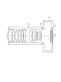
- It is a sectional view of an imaging device. It is a front perspective view showing the appearance of an imaging device. It is a rear perspective view of an imaging device.
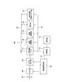
- FIG. 2 is a configuration block diagram of an internal circuit of a main part of the imaging device. It is a sectional view of a projection device.
- the imaging optical system is an imaging optical system that forms a conjugate relationship between a conjugate point on the enlargement side with a long distance and a conjugate point on the reduction side with a short distance, and the imaging optical system
- the first lens group having negative refractive power
- the second lens group having positive refractive power
- the third lens group having positive refractive power
- the fourth lens group and the fourth lens group 5 lens group
- the first lens group includes a first negative lens positioned closest to the enlargement side and a first negative lens positioned closest to the reduction side
- the second lens group includes, in order from the enlargement side, the second cemented lens and one or more positive lens components
- the third lens group includes the second lens group from the enlargement side.
- the lens component has one or more positive lens components and a third cemented lens, and the lens components have an enlargement side and a reduction side in the light path.
- the first cemented lens has a negative lens on the most reduction side
- the surface on the most reduction side has a concave surface on the reduction side
- the second cemented lens is positive. It is characterized in that it has a refractive power
- the surface on the most enlargement side has a concave surface on the enlargement side
- the third cemented lens has a positive refractive power and has a negative lens on the reduction side.
- the concept of the lens component includes a single lens, a cemented lens, and a compound lens.
- the description of the image forming optical system according to the present embodiment will be made using a predetermined lens group.
- the predetermined lens group is composed of all lenses having a negative refractive power and located between the lens located on the most enlargement side and the first cemented lens.
- the predetermined lens group corresponds to the first lens group.
- the imaging optical system of the present embodiment will be described while comparing the imaging optical system of the present embodiment with a Gauss type optical system.
- the object side corresponds to the enlargement side
- the image side corresponds to the reduction side.
- the Gauss-type optical system comprises a characteristic set of cemented lenses.
- one cemented lens has a negative lens closest to the image side, and the surface closest to the image side has a concave surface facing the image side.
- the imaging optical system of the present embodiment also includes a characteristic set of cemented lenses, that is, a first cemented lens and a second cemented lens.
- the first cemented lens has a negative lens on the most reduction side, and the surface on the most reduction side has a concave surface on the reduction side.
- the first cemented lens corresponds to one cemented lens.
- the object side group includes one cemented lens.
- the predetermined lens group includes the first cemented lens. Therefore, a predetermined lens group corresponds to the object side group.
- the refractive power is larger in the image side group than in the object side group.
- both the refractive power of the object side group and the refractive power of the image side group are positive refractive power.
- the predetermined lens group has negative refractive power. If the distribution state of refractive power is compared with a Gaussian type optical system, in the imaging optical system of this embodiment, negative refractive power is distributed to the object side group.
- the predetermined lens group can be said to be an object side group when the refractive power is shifted from the positive refractive power to the negative refractive power in the Gaussian type optical system.
- the refractive power to be shifted may be weak positive refractive power.
- the refractive power in this case is weaker than the refractive power of the object side group in the Gaussian type optical system.
- the Gauss type optical system is an optical system having an extremely high potential for aberration correction even if the F number is about 1.4, as long as the angle of view is up to about 50 °.
- the height of the potential for this aberration correction is based on a unique set of cemented lenses.
- the imaging optics of the present embodiment a configuration is employed in which the refractive power shift in the object side group and the positive refractive power in the image side group are performed with respect to the Gaussian type optical system. Therefore, the imaging optics of this embodiment are different from the Gaussian type optical system.
- the imaging optical system of the present embodiment also includes a characteristic set of cemented lenses. Therefore, the imaging optical system of the present embodiment is based on an optical system in which the potential for aberration correction is extremely high. Therefore, in the image forming optical system according to the present embodiment, (I) reducing the F-number while correcting various aberrations well, that is, securing sufficient brightness in the optical system, (II) sufficient It is possible to shorten the focal length of the entire imaging optical system while securing a back focus of the length, and (III) to secure a wide enough angle of view.
- the refractive power shift in the object side group is to shift the refractive power of the object side group from the original positive refractive power to the negative refractive power in a Gaussian type optical system. Further, the increase of the positive refractive power in the image side group is to make the positive refractive power of the image side group larger than the original refractive power in the Gaussian type optical system.
- the height of the chief ray in the image side group becomes extremely high.
- the aberration in the image side group is deteriorated.
- the predetermined lens group has negative refractive power. Therefore, in order to avoid the deterioration of the aberration in the image side group, it is preferable that the aperture stop be positioned on the reduction side more than the second cemented lens also in the image forming optical system of the present embodiment.
- the imaging optical system of the present embodiment is based on a Gaussian type optical system. Therefore, the imaging optical system of the present embodiment is also an optical system in which the potential for aberration correction is extremely high. As such, even if the aperture stop is positioned closer to the reduction side than the second cemented lens, it is possible to prevent the deterioration of the aberration to some extent.
- the aperture stop is positioned closer to the reduction side than the second cemented lens, the position of the aperture stop with respect to a unique set of cemented lenses is different from that of the Gaussian type optical system. Therefore, when the aperture stop is positioned closer to the reduction side than the second cemented lens, it is difficult to correct the aberration at a higher level.
- the third cemented lens is newly provided.
- This third cemented lens has a negative lens on the reduction side.
- the third cemented lens can be made to function as an aplanatic achromatic lens.
- the third cemented lens in addition to the first cemented lens and the second cemented lens, in the image forming optical system of the present embodiment, spherical aberration and coma aberration which are particularly difficult to correct for aberration.
- Axial chromatic aberration and lateral chromatic aberration can be corrected to a satisfactory level.
- a wide angle of view is, for example, an angle of view of 70 ° or more, and a small F number is, for example, about 1.2.
- the image forming optical system of the present embodiment is an optical system in which the potential for aberration correction is extremely high.
- the potential of this extremely high aberration correction is obtained by providing the following configuration.
- the first lens group has a first negative lens positioned closest to the enlargement side and a first cemented lens positioned closest to the reduction side.
- the second lens unit includes, in order from the enlargement side, a second cemented lens and one or more positive lens components.
- the third lens group includes, in order from the enlargement side, one or more positive lens components and a third cemented lens.
- the aperture stop is positioned closer to the reduction side than the second cemented lens. Specifically, the aperture stop is disposed in the second lens group.
- the imaging optical system includes, in order from the magnification side, a first lens group having negative refractive power, a second lens group having positive refractive power, a third lens group having positive refractive power, and a fourth lens It is composed of a group and a fifth lens group. Then, the refractive power of the first lens group is shifted from the positive refractive power to the negative refractive power in the Gaussian type optical system, while the second lens group and the third lens group are compared to the Gaussian type optical system. Give a greater positive refractive power.
- the first cemented lens has a negative lens on the most reduction side, and the surface on the most reduction side has a concave surface on the reduction side. Further, the second cemented lens has positive refractive power, and the surface on the most enlargement side has a concave surface on the enlargement side.
- the third cemented lens has positive refractive power and has a negative lens on the reduction side. Also, the lens component is a lens block in which only the enlargement side and the reduction side are in contact with air in the optical path.
- each cemented lens is as follows.
- the first cemented lens is composed of, in order from the enlargement side, a positive lens and a negative lens, and the surface closest to the reduction side has a concave surface facing the reduction side.
- the second cemented lens is composed of a negative lens and a positive lens, and the surface closest to the magnification side has a concave surface facing the magnification side.
- the third cemented lens is composed of a positive lens and a negative lens in order from the enlargement side.
- M 5 _ 3 G is the lateral magnification of the third lens unit when focusing on an infinite object
- M 5 — 4G is a lateral magnification of the fourth lens unit at infinity of objects at infinity
- the imaging optical system of the present embodiment a configuration in which the refractive power shift in the object side group and the positive refractive power in the image side group are performed is adopted for the Gaussian type optical system.
- the refractive power shift in the object side group and the positive refractive power in the image side group are performed is adopted for the Gaussian type optical system.
- the second lens group having a positive refractive power, the third lens group having a positive refractive power, and the positive side are provided on the reduction side of the predetermined lens group.
- a fifth lens group having a negative refractive power As described above, the lens units on the most reduction side are divided in such a manner that they have clear negative refractive power.
- the entire optical system has five lens groups of negative refractive power, positive refractive power, positive refractive power, positive refractive power, and negative refractive power.
- conditional expression (1) in the relationship between the third lens group having negative refractive power and the fourth lens group having positive refractive power.
- conditional expression (1) If the upper limit value of the conditional expression (1) is exceeded, it will be difficult to correct each of spherical aberration, coma and astigmatism to a satisfactory level. On the other hand, when the value goes below the lower limit value of the conditional expression (1), it becomes difficult to secure a back focus of a necessary length.
- conditional expression (1 ′) be satisfied instead of the conditional expression (1).
- R 2GF is a paraxial radius of curvature of the surface located on the most enlargement side in the second lens unit
- R 2GR is a paraxial radius of curvature of the surface located closest to the reduction side in the second lens group
- the reduction side of the predetermined lens unit is configured by four lens units from the second lens unit to the fifth lens unit.
- the second lens group includes the second cemented lens and one or more positive lens components in order from the enlargement side. Furthermore, in the Gaussian type optical system, when the aperture stop is positioned on the reduction side relative to the second cemented lens in the same manner as when the aperture stop is moved to the image side with respect to the other cemented lens. good.
- conditional expression (2) it is possible to prevent the deterioration of the on-axis aberration and the deterioration of the off-axis aberration.
- conditional expression (2) If the upper limit value of the conditional expression (2) is exceeded, spherical aberration and coma aberration are likely to be deteriorated. Therefore, it is not preferable to exceed the upper limit value of the conditional expression (2). On the other hand, below the lower limit value of the conditional expression (2), astigmatism tends to deteriorate.
- conditional expression (2) it is good to replace with conditional expression (2) and to satisfy the following conditional expressions (2 ').
- -8 ⁇ (R 2GF + R 2GR ) / (R 2GF -R 2GR) ⁇ - 1 (2 ')
- conditional expression (2) it is more preferable to satisfy the following conditional expression (2 ′ ′).
- -4.5 ⁇ (R 2GF + R 2GR ) / (R 2GF -R 2GR) ⁇ - 3.5 (2 '')
- the first positive lens positioned closest to the second cemented lens, and to satisfy the following conditional expression (3).
- R P1F is a paraxial radius of curvature of the enlargement side of the first positive lens
- R P1R is the paraxial radius of curvature of the reduction side of the first positive lens
- the reduction side of the predetermined lens unit is configured by four lens units from the second lens unit to the fifth lens unit.
- the second lens group includes the second cemented lens and one or more positive lens components in order from the enlargement side. Furthermore, in the Gaussian type optical system, it is preferable to position the aperture stop on the reduction side of the second cemented lens in the same manner as moving the aperture stop to the image side with respect to the other cemented lens. .
- conditional expression (3) it is possible to prevent the deterioration of the on-axis aberration and the deterioration of the off-axis aberration.
- conditional expression (3) If the upper limit value of the conditional expression (3) is exceeded, spherical aberration and coma aberration are likely to be deteriorated. Therefore, it is not preferable to exceed the upper limit value of the conditional expression (3). On the other hand, below the lower limit value of the conditional expression (3), astigmatism tends to deteriorate.
- conditional expression (3) it is good to replace with conditional expression (3) and to satisfy the following conditional expressions (3 '). 0.01 ⁇ (R P1F + R P1R ) / (R P1F ⁇ R P1R ) ⁇ 1 (3 ′) Furthermore, it is more preferable to satisfy the following conditional expression (3 ′ ′) instead of the conditional expression (3). 0.05 ⁇ (R P1F + R P1R ) / (R P1F -R P1R ) ⁇ 0.6 (3 ′ ′)
- the imaging optical system of the present embodiment is an original of a Gaussian type optical system. Then, in accordance with the specifications, in the object side group and the image side group, the positive / negative of the refractive power and the absolute value of the refractive power are changed, and the detailed configuration is changed to ensure high imaging performance.
- the Gaussian type optical system is composed of an object side group and an image side group, and as a whole, is configured of six lenses or seven lenses.
- the configuration is represented by, for example, positive, negative, positive, negative, positive, positive, positive, negative, negative, positive, negative, positive from the object side.
- “positive” is a positive lens
- “negative” is a negative lens
- “positive / negative” and “negative positive” are cemented lenses
- S” is an aperture stop
- ⁇ is an air gap. Further, it can be divided into an object side group and an image side group with the aperture stop S as a boundary. There is also a configuration in which a positive lens is further disposed in the image side group.
- an air gap between the third lens unit and the fifth lens unit changes at the time of focusing.
- the part where the variation of each aberration is small is the air gap between the third lens group and the fifth lens group. Therefore, by changing the air gap between the third lens unit and the fifth lens unit at the time of focusing, it is possible to suppress the variation occurring on the image plane with respect to spherical aberration, coma and astigmatism to an acceptable level. Can.
- R 5 GF is a paraxial radius of curvature of the surface located closest to the magnification side in the fifth lens group
- R 5GR is a paraxial radius of curvature of the surface located closest to the reduction side in the fifth lens group
- the portion corresponding to the image side group of the Gaussian type optical system, that is, the reduction side with respect to the predetermined lens group is configured by four lens groups in the image forming optical system of this embodiment.
- the arrangement of refractive powers is, in order from the enlargement side, positive refractive power, positive refractive power, positive refractive power, and negative refractive power.
- Conditional expression (4) is a conditional expression of the lens unit positioned closest to the reduction side.
- the conditional expression (4) is a conditional expression regarding the fifth lens group.
- conditional expression (4) As the upper limit value of conditional expression (4) is exceeded, astigmatism tends to be large. Therefore, it is not preferable to exceed the upper limit value of the conditional expression (4). On the other hand, if the lower limit value of the conditional expression (4) is not reached, spherical aberration and coma aberration are apt to deteriorate.
- conditional expression (4) it is preferable to satisfy the following conditional expression (4 ′).
- conditional expression (4 ′ ) -4 ⁇ (R 5GF + R 5GR ) / (R 5GF -R 5GR ) ⁇ -0.5 (4 ')
- conditional expression (4 ′ ′) instead of the conditional expression (4).
- -2.5 ⁇ (R 5GF + R 5GR ) / (R 5GF -R 5GR ) ⁇ -1.7 (4 '')
- the fourth lens group is configured of one lens, and the one lens is a second positive lens, and satisfies the following conditional expression (5): Is preferred. 0.01 ⁇ (R P2F + R P2R ) / (R P2F ⁇ R P2R ) ⁇ 2 (5) here, R P2F is the paraxial radius of curvature of the enlargement side of the second positive lens, R P2R is a paraxial radius of curvature of the reduction side of the second positive lens, It is.
- the portion corresponding to the image side group of the Gaussian type optical system, that is, the reduction side with respect to the predetermined lens group is configured by four lens groups in the image forming optical system of this embodiment.
- the arrangement of refractive powers is, in order from the enlargement side, positive refractive power, positive refractive power, positive refractive power, and negative refractive power.
- the fourth lens group with a single lens and satisfying the conditional expression (5), it is possible to simultaneously correct the remaining spherical aberration, coma and astigmatism to a satisfactory level. it can.
- conditional expression (5) If the upper limit value of the conditional expression (5) is exceeded, spherical aberration and coma aberration are apt to deteriorate. On the other hand, below the lower limit value of conditional expression (5), astigmatism tends to be large. Therefore, it is unpreferable to be less than the lower limit of conditional expression (5).
- conditional expression (5 ′) be satisfied instead of the conditional expression (5).
- the first negative lens is preferably a meniscus lens.
- the predetermined lens group is given negative refractive power.
- a negative lens in particular as the lens located on the most enlargement side.
- the negative lens disposed closest to the magnification side has a greater influence on the amount of off-axis aberration generated than negative lenses placed at other positions. Therefore, by making the shape of the negative lens a meniscus shape, it is possible to prevent the deterioration of off-axis aberration. As a result, it is possible to realize an imaging optical system in which various aberrations are well corrected while having a wide angle of view and a small F number.
- R N1F is a paraxial radius of curvature of the enlargement side of the first negative lens
- R N1 R is the paraxial radius of curvature of the reduction side of the first negative lens
- conditional expression (6) As the upper limit value of the conditional expression (6) is exceeded, astigmatism or coma aberration is apt to deteriorate. On the other hand, below the lower limit value of the conditional expression (6), barrel distortion tends to be large. Therefore, it is not preferable to fall below the lower limit value of the conditional expression (6).
- conditional expression (6) it is preferable to satisfy the following conditional expression (6 ′). 1 ⁇ (R N1F + R N1R ) / (R N1F -R N1R) ⁇ 4 (6 ') Furthermore, in place of the conditional expression (6), it is more preferable to satisfy the following conditional expression (6 ′ ′). 2.15 ⁇ (R N1F + R N1R ) / (R N1F -R N1R) ⁇ 2.75 (6 '')
- the third lens group has a negative lens component on the reduction side relative to the third cemented lens
- the fourth lens group has positive refractive power and a positive lens.
- the fifth lens unit have a negative refractive power and a negative lens component.
- the imaging optical system By configuring the imaging optical system in this way, it is possible to realize an imaging optical system in which various aberrations are well corrected while having a wide angle of view and a small F number. In addition, even when the number of lenses is increased to improve the optical performance, it is possible to secure an appropriate principal point position. Also, even if a larger positive refracting power is given on the reduction side than a predetermined lens group as compared with a Gaussian type optical system, correction is made to a level that can satisfy spherical aberration, coma, axial chromatic aberration and lateral chromatic aberration. be able to.
- D 3G is the amount of movement of the third lens unit during focusing
- D 4G is the amount of movement of the fourth lens unit during focusing
- the part where the variation of each aberration is small is the air gap between the third lens group and the fifth lens group. Therefore, by changing the air gap between the third lens unit and the fifth lens unit at the time of focusing, it is possible to suppress the variation occurring on the image plane with respect to spherical aberration, coma and astigmatism to an acceptable level. Can.
- conditional expression (7) it is possible to further suppress the variation occurring on the image plane with respect to spherical aberration, coma and astigmatism.
- conditional expression (7 ′) be satisfied instead of the conditional expression (7).
- the third lens unit includes, in order from the enlargement side, a positive lens component, a third cemented lens, and a negative lens component, and the third cemented lens is It is preferable that the negative lens component of the third lens group has a biconcave shape in order from the enlargement side, which is composed of a positive lens and a negative lens.
- the third lens group By configuring the third lens group in this manner, it is possible to realize an imaging optical system in which various aberrations are favorably corrected while having a wide angle of view and a small F number. In addition, even when the number of lenses is increased to improve the optical performance, it is possible to secure an appropriate principal point position. Also, even if a larger positive refracting power is given on the reduction side than a predetermined lens group as compared with a Gaussian type optical system, correction is made to a level that can satisfy spherical aberration, coma, axial chromatic aberration and lateral chromatic aberration. be able to.
- f is the focal length of the entire imaging optical system when an object at infinity is in focus
- e N1F is the maximum effective aperture of the enlargement side of the first negative lens
- conditional expression (A) If the upper limit value of the conditional expression (A) is exceeded, it will be difficult to widen the angle of view. That is, when trying to widen the angle of view, spherical aberration, distortion and astigmatism tend to occur. On the other hand, when the value goes below the lower limit value of the conditional expression (A), the optical system tends to be enlarged in the radial direction.
- conditional expression (A ′) be satisfied instead of the conditional expression (A).
- f is the focal length of the entire imaging optical system when focusing on an infinite object
- e AS is the maximum diameter of the aperture stop
- Fno is the f-number of the entire imaging optical system when focusing on an infinite object
- conditional expression (B) If the upper limit value of the conditional expression (B) is exceeded, it will be difficult to widen the angle of view. That is, if the angle of view is increased, it becomes difficult to correct spherical aberration and chromatic aberration. On the other hand, when the value goes below the lower limit value of the conditional expression (B), the optical system tends to be enlarged in the radial direction.
- conditional expression (B) In place of the conditional expression (B), it is preferable to satisfy the following conditional expression (B ′). 0.2 ⁇ (f / e AS ) / Fno ⁇ 1 (B ') Furthermore, it is more preferable to satisfy the following conditional expression (B ′ ′) instead of the conditional expression (B). 0.3 ⁇ (f / e AS ) / Fno ⁇ 0.9 (B '')
- T air — max is the largest on-axis air distance between the surface on the most enlargement side of the imaging optical system and the surface on the most reduction side
- ⁇ d is the on-axis distance from the surface on the most enlargement side of the imaging optical system to the surface on the most reduction side
- Conditional expression (C) is a conditional expression that is advantageous for securing high optical performance, shortening the overall length of the optical system, and reducing the outer diameter of the imaging system.
- ⁇ d ie, the on-axis distance from the lens surface located on the most expansion side of the imaging optical system to the lens surface located on the most reduction side, excessively enlarges the air gap between the lenses to achieve optical performance. Securing easily leads to an increase in the overall length of the optical system and an increase in the diameter of the optical system.
- conditional expression (C) is advantageous for securing the number of lenses necessary for realizing high optical performance while shortening the overall length and reducing the diameter of the optical system.
- conditional expression (C ′) be satisfied instead of the conditional expression (C). 0.03 ⁇ T air_max / ⁇ d ⁇ 0.2 ( C ′) Furthermore, it is more preferable to satisfy the following conditional expression (C ′ ′) in place of the conditional expression (C). 0.07 ⁇ T air_max / ⁇ d ⁇ 0.16 ( C ′ ′)
- the optical device includes an optical system and an imaging device disposed on the reduction side, and the imaging device has an imaging surface, and an image formed on the imaging surface by the optical system is It is characterized in that it is converted into an electrical signal, and the optical system is the above-mentioned image forming optical system.
- a wide imaging range can be imaged with low noise and high resolution.
- the optical device of the present embodiment has an optical system and a display element arranged on the reduction side, the display element has a display surface, and the image displayed on the display surface is an optical system.
- the optical system is projected on the enlargement side, and the optical system is the above-mentioned imaging optical system.
- optical device of the present embodiment it is possible to project an image with low noise and high resolution over a wide projection range.
- imaging optical system and optical device may simultaneously satisfy a plurality of configurations. This is preferable in order to obtain a good imaging optical system and optical device. Moreover, the combination of preferable structure is arbitrary. Further, for each conditional expression, only the upper limit value or the lower limit value of the numerical range of the more limited conditional expression may be limited.
- the imaging optical systems of Embodiments 1 and 2 are imaging optical systems in which the f-number is less than 1.5.
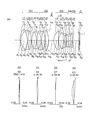
- FIG. 1A and FIG. 2A show lens cross sections in the imaging optical system of each embodiment.
- the lens sectional view is a lens sectional view at the time of focusing on an infinite distance object.
- FIGS. 1 (b) and 2 (b) show spherical aberration (SA) in the imaging optical system of each example, and FIGS. 1 (c) and 2 (c) show astigmatism (AS). 1 (d) and 2 (d) show distortion (DT), and FIGS. 1 (e) and 2 (e) show distortion (DT).
- SA spherical aberration
- FIGS. 1 (c) and 2 (c) show astigmatism (AS).
- 1 (d) and 2 (d) show distortion (DT)
- FIGS. 1 (e) and 2 (e) show distortion (DT).
- Each aberration diagram is an aberration diagram at the time of focusing on an infinite distance object. “ ⁇ ” represents a half angle of view.
- the first lens group is G1
- the second lens group is G2
- the third lens group is G3
- the fourth lens group is G4
- the fifth lens group is G5
- the cover glass is C.
- the image plane is shown by I.
- the imaging optical system of each embodiment can be divided into a front group and a rear group.
- the first lens group G1 corresponds to the front group
- the remaining lens groups correspond to the rear group.
- a parallel flat plate constituting a low pass filter may be disposed between the fifth lens group G5 and the image plane I.
- the surface of the parallel flat plate may be provided with a wavelength range limiting coat for limiting infrared light.
- a multilayer film for wavelength range limitation may be provided on the surface of the cover glass C. Further, the cover glass C may have a low pass filter action.
- an imaging element is disposed on the image plane I.
- a display element is disposed on the image plane I.
- the configuration of each embodiment will be described on the premise that the imaging optical system is used for imaging. Therefore, the enlargement side is the object side, and the reduction side is the image side.
- FIG. 1A is a lens cross-sectional view of the image forming optical system according to the first embodiment.
- 1 (b), (c), (d) and (e) are aberration diagrams of the imaging optical system according to Example 1.
- FIG. 1A is a lens cross-sectional view of the image forming optical system according to the first embodiment.
- 1 (b), (c), (d) and (e) are aberration diagrams of the imaging optical system according to Example 1.
- FIG. 1A is a lens cross-sectional view of the image forming optical system according to the first embodiment.
- 1 (b), (c), (d) and (e) are aberration diagrams of the imaging optical system according to Example 1.
- the image forming optical system according to Example 1 includes, in order from the object side, a first lens group G1 having negative refractive power and a second lens group G2 having positive refractive power. And a third lens group G3 having a positive refractive power, a fourth lens group G4 having a positive refractive power, and a fifth lens group G5 having a negative refractive power.
- the second lens group G2 includes an aperture stop S.
- the first lens group G1 has a negative meniscus lens L1 having a convex surface on the object side, a negative meniscus lens L2 having a convex surface on the object side, a negative meniscus lens L3 having a convex surface on the image side, and a biconvex positive lens It is composed of L4, a biconvex positive lens L5, and a biconcave negative lens L6.
- the biconvex positive lens L5 and the biconcave negative lens L6 are cemented.
- the second lens group G2 is composed of a biconcave negative lens L7, a biconvex positive lens L8, and a biconvex positive lens L9.
- the biconcave negative lens L7 and the biconvex positive lens L8 are cemented.
- the third lens group G3 is composed of a positive meniscus lens L10 having a convex surface facing the object, a biconvex positive lens L11, a biconcave negative lens L12, and a biconcave negative lens L13.
- the biconvex positive lens L11 and the biconcave negative lens L12 are cemented.
- the fourth lens group G4 is composed of a biconvex positive lens L14.
- the fifth lens group G5 is composed of a negative meniscus lens L15 having a convex surface facing the image side.
- the first lens group G1 is a predetermined lens group.
- a first cemented lens is composed of the biconvex positive lens L5 and the biconcave negative lens L6.
- a second cemented lens is configured by the biconcave negative lens L7 and the biconvex positive lens L8.
- a third cemented lens is configured by the biconvex positive lens L11 and the biconcave negative lens L12.
- the positive meniscus lens L10, the biconvex positive lens L11, the biconcave negative lens L12, and the biconcave negative lens L13 are integrated together along the optical axis toward the object side. While moving, the biconvex positive lens L14 moves to the object side along the optical axis.
- Aspheric surfaces are provided on five surfaces in total: both surfaces of the negative meniscus lens L2, both surfaces of the positive meniscus lens L10, and the image side surface of the biconcave negative lens L13.
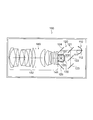
- FIG. 2A is a lens cross-sectional view of the imaging optical system according to the second embodiment.
- FIGS. 2B, 2C, 2D, and 2E are aberration diagrams of the imaging optical system according to Example 2.
- FIG. 2A is a lens cross-sectional view of the imaging optical system according to the second embodiment.
- FIGS. 2B, 2C, 2D, and 2E are aberration diagrams of the imaging optical system according to Example 2.
- the imaging optical system according to Example 2 includes, in order from the object side, a first lens group G1 having negative refractive power and a second lens group G2 having positive refractive power. And a third lens group G3 having a positive refractive power, a fourth lens group G4 having a positive refractive power, and a fifth lens group G5 having a negative refractive power.
- the second lens group G2 includes an aperture stop S.
- the first lens group G1 includes a negative meniscus lens L1 having a convex surface facing the object, a biconcave negative lens L2, a biconvex positive lens L3, a biconvex positive lens L4, and a biconcave negative lens L5. It is done.
- the biconcave negative lens L2 and the biconvex positive lens L3 are cemented.
- the biconvex positive lens L4 and the biconcave negative lens L5 are cemented.
- the second lens group G2 is composed of a biconcave negative lens L6, a biconvex positive lens L7, and a biconvex positive lens L8.
- the biconcave negative lens L6 and the biconvex positive lens L7 are cemented.
- the third lens group G3 is composed of a positive meniscus lens L9 having a convex surface facing the object, a biconvex positive lens L10, a biconcave negative lens L11, and a biconcave negative lens L12.
- the biconvex positive lens L10 and the biconcave negative lens L11 are cemented.
- the fourth lens group G4 is composed of a biconvex positive lens L13.
- the fifth lens group G5 is composed of a negative meniscus lens L14 having a convex surface facing the image side.
- the first lens group G1 is a predetermined lens group.
- a first cemented lens is composed of the biconvex positive lens L4 and the biconcave negative lens L5. Further, a second cemented lens is configured by the biconcave negative lens L6 and the biconvex positive lens L7. Further, a third cemented lens is configured of the biconvex positive lens L10 and the biconcave negative lens L11.
- the positive meniscus lens L9, the biconvex positive lens L10, the biconcave negative lens L11, and the biconcave negative lens L12 are integrated to the object side along the optical axis.
- the biconvex positive lens L13 moves to the object side along the optical axis.
- Aspheric surfaces are provided on five surfaces in total: both surfaces of the negative meniscus lens L1, both surfaces of the positive meniscus lens L9, and the image side surface of the biconcave negative lens L12.
- r 1, r 2,... Are the radius of curvature of each lens surface
- d 1, d 2,... Are the thicknesses or air gaps of each lens
- nd 1, nd 2 The refractive index of the lens, .nu.d1, .nu.d2, ... is the Abbe number of each lens
- the * mark is an aspheric surface.
- f is the focal length of the entire imaging optical system, FNO. Is an F number, ⁇ is a half angle of view, IH is an image height, and FB is a back focus.
- the total length is obtained by adding the back focus to the distance from the lens front surface to the lens final surface.
- the back focus is the air conversion of the distance from the lens final surface to the paraxial image surface.
- the unit of the angle is degrees.
- infinity is at the time of focusing on an infinite object
- near distance is at the time of focusing on a short object.
- the value at the near distance is the distance from the object to the image.
- the aspheric surface shape is expressed by the following equation, assuming that the optical axis direction is z and the direction orthogonal to the optical axis is y, the conical coefficient is k, and the aspheric coefficient is A4, A6, A8, and A10. .
- z (y 2 / r) / [1 + ⁇ 1-(1 + k) (y / r) 2 ⁇ 1/2 ] + A4y 4 + A6y 6 + A8y 8 + A10y 10
- “e ⁇ n” (n is an integer) indicates “10 ⁇ n ”.
- the symbols of these specification values are common to the numerical data of the embodiments described later.
- Numerical embodiment 1 Unit mm Surface data surface number r d nd d d Object ⁇ ⁇ 1 80.982 1.55 1.48749 70.23 2 31.093 11.04 3 * 70.066 2.06 1.49700 81.61 4 * 23.874 20.90 5 -44.198 2.00 1.58267 46.42 6-364.034 0.41 7 121.274 10.00 1.84666 23.78 8 -143.318 4.33 9 53.195 8.29 1.69680 55.53 10 -49.889 1.51 1.80518 25.42 11 231.869 5.78 12 -45.268 1.52 1.69895 30.13 13 46.454 8.54 1.49700 81.61 14 -77.694 0.40 15 90.149 8.00 1.84666 23.78 16 -78.759 1.20 17 (aperture) ⁇ ⁇ variable 18 * 29.688 9.46 1.49700 81.61 19 * 155.316 0.40 20 32.436 9.37 1.43875 94.93 21 -61.2
- Conditional Expression Example 1 Example 2 (1) M 5_3G / M 5_4G 0.927 0.537 (2) (R 2GF + R 2GR) / (R 2GF -R 2GR) -3.703 -4.191 (3) (R P1F + R P1R ) / (R P1F -R P1R ) 0.067 0.542 (4) ( R5GF + R5GR ) / ( R5GF- R5GR )-1.943-2.318 (5) (R P2F + R P2R ) / (R P2F -R P2R ) 0.288 0.475 (6) (R N1F + R N1R) / (R N1F -R N1R) 2.247 2.698 (7) D 3G / D 4G 0.899 2.972 (A) f / e N1F 0.366 0.913 (B) (f
- Examples of the optical device according to the present embodiment include an imaging device and a projection device. Hereinafter, specific examples of the imaging device and the projection device will be described.
- FIG. 3 is a cross-sectional view of a single-lens mirrorless camera as an imaging device.
- a photographing optical system 2 is disposed in a lens barrel of a single-lens mirrorless camera 1.
- the mount unit 3 enables the taking optical system 2 to be detachably attached to the body of the single-lens mirrorless camera 1.
- a screw type mount, a bayonet type mount, or the like is used as the mount portion 3.
- a bayonet type mount is used in the body of the single-lens mirrorless camera 1 disposed in the body of the single-lens mirrorless camera 1, an imaging element surface 4 and a back monitor 5 are disposed.
- the imaging device a compact CCD or CMOS is used.
- the photographing optical system 2 of the single-lens mirrorless camera 1 for example, the imaging optical system shown in the first and second embodiments is used.
- FIG. 4 and 5 show conceptual diagrams of the configuration of the imaging device.
- FIG. 4 is a front perspective view showing the appearance of a single-eye mirrorless camera 40 as an imaging device
- FIG. 5 is a rear perspective view of the same.
- the imaging optical system shown in the first and second embodiments is used for the photographing optical system 41 of the single-lens mirrorless camera 40.
- the single-lens mirrorless camera 40 of this embodiment includes a photographing optical system 41 located on the photographing optical path 42, a shutter button 45, a liquid crystal display monitor 47, and the like, and the shutter button 45 disposed above the single-lens mirrorless camera 40.
- the photographing is performed through the photographing optical system 41, for example, the imaging optical system of the first embodiment.
- An object image formed by the photographing optical system 41 is formed on an image pickup element (photoelectric conversion surface) provided in the vicinity of the imaging surface.
- the object image received by the imaging device is displayed as an electronic image on the liquid crystal display monitor 47 provided on the back of the camera by the processing means. Also, the captured electronic image can be recorded in the storage means.
- FIG. 6 is a block diagram showing an internal circuit of a main part of the single-eye mirrorless camera 40.
- the above-mentioned processing means is composed of, for example, the CDS / ADC unit 24, the temporary storage memory 17, the image processing unit 18 and the like, and the storage means is composed of the storage medium unit 19 and the like.
- the single-lens mirror-less camera 40 is connected to the operation unit 12, the control unit 13 connected to the operation unit 12, and the control signal output port of the control unit 13 via buses 14 and 15.
- the imaging drive circuit 16 the temporary storage memory 17, the image processing unit 18, the storage medium unit 19, the display unit 20, and the setting information storage memory unit 21 are provided.
- the temporary storage memory 17, the image processing unit 18, the storage medium unit 19, the display unit 20, and the setting information storage memory unit 21 can mutually input and output data via the bus 22. Further, a CCD 49 and a CDS / ADC unit 24 are connected to the imaging drive circuit 16.
- the operation unit 12 includes various input buttons and switches, and notifies the control unit 13 of event information input from the outside (camera user) via these.
- the control unit 13 is a central processing unit including, for example, a CPU, incorporates a program memory (not shown), and controls the entire single-lens mirrorless camera 40 in accordance with a program stored in the program memory.
- the CCD 49 is an image pickup device which is drive-controlled by the image pickup drive circuit 16, converts the light amount of each pixel of the object image formed through the photographing optical system 41 into an electric signal, and outputs the electric signal to the CDS / ADC unit 24.
- the CDS / ADC unit 24 amplifies the electrical signal input from the CCD 49, performs analog / digital conversion, and performs raw video data (Bayer data, hereinafter referred to as RAW data) that has only been subjected to this amplification and digital conversion. Are output to the temporary storage memory 17.
- the temporary storage memory 17 is a buffer made of, for example, an SDRAM or the like, and is a memory device that temporarily stores the RAW data output from the CDS / ADC unit 24.
- the image processing unit 18 reads out the RAW data stored in the temporary storage memory 17 or the RAW data stored in the storage medium unit 19, and includes distortion correction based on the image quality parameter designated by the control unit 13. It is a circuit that electrically performs various image processing.
- the storage medium unit 19 detachably mounts, for example, a card type or stick type recording medium including a flash memory, and RAW data transferred from the temporary storage memory 17 or the image processing unit 18 to these flash memories. The image data subjected to the image processing is recorded and held.
- the display unit 20 is configured by a liquid crystal display monitor 47 or the like, and displays captured RAW data, image data, an operation menu, and the like.
- the setting information storage memory unit 21 is provided with a ROM unit in which various image quality parameters are stored in advance, and a RAM unit which stores the image quality parameters read from the ROM unit by the input operation of the operation unit 12.
- the imaging optical system of the present invention by adopting the imaging optical system of the present invention as the imaging optical system 41, a wide imaging range can be imaged with low noise and high resolution.
- the imaging optical system of the present invention can also be used in an imaging apparatus of the type having a quick return mirror.
- FIG. 7 is a cross-sectional view of a projector as a projection device.
- the projector 100 includes a light source unit 110, an illumination unit 120, an image forming unit 130, and a projection unit 140.
- the light source unit 110 has a light source 111 and a reflecting member 112. Illumination light is emitted from the light source 111.
- the illumination light is white light.
- the illumination light is reflected by the reflection member 112 and enters the illumination unit 120.
- the illumination unit 120 includes a first dichroic mirror 121, a second dichroic mirror 122, a third dichroic mirror 123, a first reflecting member 124, and a second reflecting member 125.
- the first dichroic mirror 121 transmits light in a red wavelength range (hereinafter, referred to as “red light”), and reflects light in other wavelength ranges.
- the second dichroic mirror 122 reflects light in the green wavelength range (hereinafter referred to as “green light”) and transmits light in the other wavelength ranges.
- the third dichroic mirror 123 reflects light in the blue wavelength range (hereinafter referred to as “blue light”) and transmits light in the other wavelength ranges.
- the red light, the green light and the blue light enter the image forming unit 130.
- a normal plane reflecting mirror may be used.
- the image forming unit 130 includes a first display element 131, a second display element 132, and a third display element 133.
- Red light is emitted to the first display element 131 via the first reflection member 124.
- the second display element 132 is irradiated with green light. Blue light is emitted to the third display element 133 via the second reflection member 125.
- the same image is displayed on the first display element 131, the second display element 132, and the third display element 133.
- a red image is displayed on the first display element 131
- a green image is displayed on the second display element 132
- a blue image is displayed on the third display element 133.
- the projection unit 140 has a dichroic prism 141 and a projection optical system 142.
- the light emitted from the first display element 131, the second display element 132, and the third display element 133 is synthesized by the dichroic prism 141.
- the dichroic prism 141 combines three images.
- the projection optical system 142 projects the three combined images at predetermined positions.
- the projection optical system 142 for example, the imaging optical system shown in the first and second embodiments is used.
- the image forming unit 130 may be a light valve such as a DMD (digital mirror device).
- the light from the light source unit 110 may be reflected by the light valve, and the image from the light valve may be enlarged and projected by the projection unit 140.
- the projector 100 configured as described above, by adopting the imaging optical system of the present invention as the projection optical system 142, it is possible to project an image with low noise and high resolution in a wide projection range.
- the imaging optical system according to the present invention is suitable for an imaging optical system in which various aberrations are well corrected while having a wide angle of view and a small F number.
- the optical device according to the present invention is suitable for an imaging device for imaging a wide imaging range with low noise and high resolution, and a projection device for projecting an image with low noise and high resolution on a wide projection range.
Abstract
An image-forming optical system is configured from: a first lens group G1 having a negative refractive power; a second lens group G2 having a positive refractive power; a third lens group G3 having a positive refractive power; a fourth lens group G4; and a fifth lens group G5. The image-forming optical system comprises an optical stop S within the second lens group G2. The first lens group G1 comprises a first negative lens and a first cemented lens. The second lens group G2 comprises a second cemented lens and one or a plurality of positive lens components. The third lens group G3 comprises one or a plurality of positive lens components and a third cemented lens. The first cemented lens has a negative lens on the side thereof that is farthest to the reduction side and comprises a concave surface that faces the reduction side. The second cemented lens has a positive refractive power and comprises a concave surface that faces the enlargement side. The third cemented lens has a positive refractive power and comprises a negative lens on the reduction side thereof.
Description
本発明は、結像光学系及びそれを備えた光学装置に関する。
The present invention relates to an imaging optical system and an optical apparatus provided with the same.
60°前後から50°前後の画角を有する撮影レンズとして、広角レンズや標準レンズ(以下、「広角撮影レンズ」という)がある。広角撮影レンズの光学系には、従来、レトロフォーカスタイプの光学系又はガウスタイプの光学系が広く用いられてきた。
There are a wide-angle lens and a standard lens (hereinafter referred to as "wide-angle shooting lens") as a shooting lens having an angle of view of around 60 ° to around 50 °. Conventionally, a retrofocus type optical system or a Gaussian type optical system has been widely used as an optical system of a wide-angle photographing lens.
レトロフォーカスタイプの光学系は、負の屈折力を有する前群と正の屈折力を有する後群とから構成されている。レトロフォーカスタイプの光学系は、十分な長さのバックフォーカスが確保できるという特徴を有している。
The retrofocus type optical system is composed of a front group having negative refractive power and a rear group having positive refractive power. The retrofocus type optical system has a feature that a sufficient back focus can be secured.
一方、ガウスタイプの光学系は、特徴的な一組の接合レンズを有する。一方の接合レンズは、最も像側に負レンズを有し、最も像側の面が像側に凹面を向けている。また、他方の接合レンズは、最も物体側の面が物体側に凹面を向けている。
On the other hand, a Gaussian type optical system has a characteristic set of cemented lenses. One cemented lens has a negative lens on the most image side, and the surface on the most image side has a concave surface on the image side. In the other cemented lens, the surface closest to the object side has a concave surface facing the object side.
ガウスタイプの光学系を2つの群に分けると、一方の接合レンズから物体側の群(以下、「物体側群」という)と他方の接合レンズから像側の群(以下、「像側群」という)とに分けることができる。
When the Gauss type optical system is divided into two groups, a group on the object side from one cemented lens (hereinafter referred to as "object side group") and a group on the image side from the other cemented lens (hereinafter "image side group" Can be divided into
なお、ガウスタイプの光学系では、屈折力の重心が光学系の像側寄りにある。すなわち、ガウスタイプの光学系では、物体側群の屈折力と像側群の屈折力は共に正の屈折力であるが、物体側群よりも像側群の方で屈折力が大きくなっている。
In the Gaussian type optical system, the center of gravity of the refractive power is closer to the image side of the optical system. That is, in the Gaussian type optical system, both the refractive power of the object side group and the refractive power of the image side group are positive refractive power, but the refractive power is larger in the image side group than in the object side group .
従来の広角撮影レンズの光学系では、画角が広くなるほど、屈折力配置が非対称になる傾向が強くなる。そのため、従来の広角撮影レンズの光学系では、画角が広くなるほど、コマ収差、非点収差及び倍率色収差が悪化し易い。なお、屈折力配置とは、正の屈折力と負の屈折力の並び方のことである。
In the optical system of the conventional wide-angle photographing lens, the wider the angle of view, the stronger the tendency of the refractive power arrangement to become asymmetric. Therefore, in the optical system of the conventional wide-angle photographing lens, coma, astigmatism and lateral chromatic aberration are apt to deteriorate as the angle of view becomes wider. In addition, refractive power arrangement | positioning is the alignment of positive refractive power and negative refractive power.
また、従来の広角撮影レンズの光学系では、Fナンバーが小さくなるほど、相対的にレンズ面の曲率が大きくなる。そのため、従来の広角撮影レンズの光学系では、Fナンバーが小さくなるほど、球面収差、コマ収差及び軸上色収差が多く発生する傾向があった。
In addition, in the optical system of the conventional wide-angle photographing lens, the curvature of the lens surface relatively increases as the F-number decreases. Therefore, in the optical system of the conventional wide-angle photographing lens, as the F-number becomes smaller, there is a tendency for more spherical aberration, coma and axial chromatic aberration to occur.
また、従来の広角撮影レンズの光学系では、正の屈折力を有する後群の有効口径が大型化するといった問題もあった。
In addition, in the optical system of the conventional wide-angle photographing lens, there is also a problem that the effective aperture of the rear group having positive refractive power is increased.
これらの問題を解決した広角撮影レンズが、各種提案されている。提案されている広角撮影レンズでは、Fナンバーが1.4程度になっている。画角が広くFナンバーが小さい広角撮影レンズの光学系として、特許文献1~6に開示された光学系がある。
Various wide-angle shooting lenses that solve these problems have been proposed. The proposed wide-angle shooting lens has an f-number of around 1.4. As an optical system of a wide angle photographing lens having a wide angle of view and a small F number, there are optical systems disclosed in Patent Documents 1 to 6.
特許文献1や特許文献2の光学系ではFナンバーが1.24であるため、Fナンバーが小さい光学系が実現できている。しかしながら、画角が63.6°であるため、特許文献1や特許文献2の光学系では、画角が十分に広い光学系が実現できていない。
In the optical systems of Patent Document 1 and Patent Document 2, since the f-number is 1.24, an optical system with a small f-number can be realized. However, since the angle of view is 63.6 °, the optical system of Patent Document 1 or Patent Document 2 can not realize an optical system with a sufficiently wide angle of view.
また、特許文献3、特許文献4、特許文献5及び特許文献6の光学系では、Fナンバーが1.4であるが、これ以上Fナンバーを小さくしようとするか、又は画角を広くしようとすると、上述した諸収差の補正がさらに困難となる。
Further, in the optical systems of Patent Document 3, Patent Document 4, Patent Document 5 and Patent Document 6, although the F number is 1.4, it is intended to further reduce the F number or to widen the angle of view. Then, the correction of the various aberrations described above becomes more difficult.
本発明は、このような課題に鑑みてなされたものであって、広い画角と小さいFナンバーを有しながらも、諸収差が良好に補正された結像光学系及びそれを備えた光学装置を提供することを目的とする。
The present invention has been made in view of such problems, and has an image forming optical system in which various aberrations are favorably corrected while having a wide angle of view and a small F number, and an optical apparatus provided with the same. Intended to provide.
上述した課題を解決し、目的を達成するために、本発明の結像光学系は、
距離が長い方の拡大側の共役点と距離が短い方の縮小側の共役点との共役関係を形成する結像光学系であって、
結像光学系は、拡大側から順に、
負の屈折力を有する第1レンズ群と、
正の屈折力を有する第2レンズ群と、
正の屈折力を有する第3レンズ群と、
第4レンズ群と、
第5レンズ群と、から構成され、
第2レンズ群内に、開口絞りを有し、
第1レンズ群は、最も拡大側に位置する第1の負レンズと、最も縮小側に位置する第1の接合レンズと、を有し、
第2レンズ群は、拡大側から順に、第2の接合レンズと、1枚又は複数枚の正レンズ成分と、を有し、
第3レンズ群は、拡大側から順に、1枚又は複数枚の正レンズ成分と、第3の接合レンズと、を有し、
レンズ成分は、光路中にて拡大側面と縮小側面のみが空気に接するレンズブロックであって、
第1の接合レンズは最も縮小側に負レンズを有し、最も縮小側の面が縮小側に凹面を向けており、
第2の接合レンズは正の屈折力を有し、最も拡大側の面が拡大側に凹面を向けており、
第3の接合レンズは正の屈折力を有し、縮小側に負レンズを有することを特徴とする。 In order to solve the problems described above and achieve the purpose, the imaging optical system of the present invention is
An imaging optical system which forms a conjugate relationship between a conjugate point on the enlargement side with a long distance and a conjugate point on the reduction side with a short distance,
The imaging optical system operates in order from the magnification side
A first lens group having negative refractive power;
A second lens group having a positive refractive power;
A third lens unit having a positive refractive power;
The fourth lens group,
And a fifth lens group,
An aperture stop is provided in the second lens group,
The first lens group has a first negative lens located closest to the magnification side and a first cemented lens located closest to the reduction side,
The second lens unit includes, in order from the enlargement side, a second cemented lens and one or more positive lens components,
The third lens unit includes, in order from the enlargement side, one or more positive lens components and a third cemented lens,
The lens component is a lens block in which only the enlargement side and reduction side are in contact with air in the optical path,
The first cemented lens has a negative lens on the most reduction side, and the surface on the most reduction side has a concave surface on the reduction side,
The second cemented lens has positive refractive power, and the surface on the most enlargement side is concave on the enlargement side,
The third cemented lens is characterized by having positive refractive power and having a negative lens on the reduction side.
また、本発明の光学装置は、
光学系と、縮小側に配置された撮像素子と、を有し、
撮像素子は撮像面を有し、且つ光学系によって撮像面上に形成された像を電気信号に変換し、
光学系が上述の結像光学系であることを特徴とする。 Also, the optical device of the present invention is
An optical system and an imaging device disposed on the reduction side,
The imaging device has an imaging surface, and converts an image formed on the imaging surface by the optical system into an electrical signal,
The optical system is characterized in that it is the above-mentioned image forming optical system.
また、本発明の光学装置は、
光学系と、縮小側に配置された表示素子と、を有し、
表示素子は表示面を有し、
表示面上に表示された画像は、光学系によって拡大側に投影され、
光学系が上述の結像光学系であることを特徴とする。 Also, the optical device of the present invention is
An optical system, and a display element disposed on the reduction side,
The display element has a display surface,
The image displayed on the display surface is projected to the enlargement side by the optical system,
The optical system is characterized in that it is the above-mentioned image forming optical system.
本発明によれば、広い画角と小さいFナンバーを有しながらも、諸収差が良好に補正された結像光学系及びそれを備えた光学装置を提供することができる。
According to the present invention, it is possible to provide an imaging optical system in which various aberrations are well corrected while having a wide angle of view and a small F number, and an optical apparatus provided with the imaging optical system.
以下に、本発明に係る結像光学系及びそれを備えた光学装置の実施形態及び実施例を、図面に基づいて詳細に説明する。なお、この実施形態及び実施例によりこの発明が限定されるものではない。
Hereinafter, embodiments and examples of an imaging optical system and an optical apparatus provided with the imaging optical system according to the present invention will be described in detail based on the drawings. The present invention is not limited by the embodiments and the examples.
本実施形態の結像光学系は、距離が長い方の拡大側の共役点と距離が短い方の縮小側の共役点との共役関係を形成する結像光学系であって、結像光学系は、拡大側から順に、負の屈折力を有する第1レンズ群と、正の屈折力を有する第2レンズ群と、正の屈折力を有する第3レンズ群と、第4レンズ群と、第5レンズ群と、から構成され、第2レンズ群内に、開口絞りを有し、第1レンズ群は、最も拡大側に位置する第1の負レンズと、最も縮小側に位置する第1の接合レンズと、を有し、第2レンズ群は、拡大側から順に、第2の接合レンズと、1枚又は複数枚の正レンズ成分と、を有し、第3レンズ群は、拡大側から順に、1枚又は複数枚の正レンズ成分と、第3の接合レンズと、を有し、レンズ成分は、光路中にて拡大側面と縮小側面のみが空気に接するレンズブロックであって、第1の接合レンズは最も縮小側に負レンズを有し、最も縮小側の面が縮小側に凹面を向けており、第2の接合レンズは正の屈折力を有し、最も拡大側の面が拡大側に凹面を向けており、第3の接合レンズは正の屈折力を有し、縮小側に負レンズを有することを特徴とする。なお、レンズ成分の概念には、単レンズ、接合レンズ、複合レンズが含まれる。
The imaging optical system according to the present embodiment is an imaging optical system that forms a conjugate relationship between a conjugate point on the enlargement side with a long distance and a conjugate point on the reduction side with a short distance, and the imaging optical system In order from the magnification side, the first lens group having negative refractive power, the second lens group having positive refractive power, the third lens group having positive refractive power, the fourth lens group, and the fourth lens group 5 lens group, and has an aperture stop in the second lens group, and the first lens group includes a first negative lens positioned closest to the enlargement side and a first negative lens positioned closest to the reduction side And the second lens group includes, in order from the enlargement side, the second cemented lens and one or more positive lens components, and the third lens group includes the second lens group from the enlargement side. In order, the lens component has one or more positive lens components and a third cemented lens, and the lens components have an enlargement side and a reduction side in the light path. The first cemented lens has a negative lens on the most reduction side, the surface on the most reduction side has a concave surface on the reduction side, and the second cemented lens is positive. It is characterized in that it has a refractive power, and the surface on the most enlargement side has a concave surface on the enlargement side, and the third cemented lens has a positive refractive power and has a negative lens on the reduction side. The concept of the lens component includes a single lens, a cemented lens, and a compound lens.
本実施形態の結像光学系の説明では、所定のレンズ群を用いて説明する。所定のレンズ群は、負の屈折力を有し、最も拡大側に位置するレンズから第1の接合レンズまでの間にあるすべてのレンズで構成されている。よって、所定のレンズ群は第1レンズ群に対応する。
The description of the image forming optical system according to the present embodiment will be made using a predetermined lens group. The predetermined lens group is composed of all lenses having a negative refractive power and located between the lens located on the most enlargement side and the first cemented lens. Thus, the predetermined lens group corresponds to the first lens group.
本願実施形態の結像光学系とガウスタイプの光学系とを比較しながら、本願実施形態の結像光学系について説明する。以下の説明では、拡大側に物体側が対応し、縮小側に像側が対応する。
The imaging optical system of the present embodiment will be described while comparing the imaging optical system of the present embodiment with a Gauss type optical system. In the following description, the object side corresponds to the enlargement side, and the image side corresponds to the reduction side.
上述のように、ガウスタイプの光学系は、特徴的な一組の接合レンズを備えている。ここで、一方の接合レンズは、最も像側に負レンズを有し、最も像側の面が像側に凹面を向けている。
As mentioned above, the Gauss-type optical system comprises a characteristic set of cemented lenses. Here, one cemented lens has a negative lens closest to the image side, and the surface closest to the image side has a concave surface facing the image side.
一方、本実施形態の結像光学系も、特徴的な一組の接合レンズ、すなわち、第1の接合レンズと第2の接合レンズとを備えている。ここで、第1の接合レンズは最も縮小側に負レンズを有し、最も縮小側の面が縮小側に凹面を向けている。よって、第1の接合レンズが一方の接合レンズに対応する。
On the other hand, the imaging optical system of the present embodiment also includes a characteristic set of cemented lenses, that is, a first cemented lens and a second cemented lens. Here, the first cemented lens has a negative lens on the most reduction side, and the surface on the most reduction side has a concave surface on the reduction side. Thus, the first cemented lens corresponds to one cemented lens.
また、ガウスタイプの光学系では、物体側群が一方の接合レンズを含んでいる。これに対して、本実施形態の結像光学系では、所定のレンズ群が第1の接合レンズを含んでいる。よって、所定のレンズ群が物体側群に対応する。
In addition, in the Gaussian type optical system, the object side group includes one cemented lens. On the other hand, in the image forming optical system of the present embodiment, the predetermined lens group includes the first cemented lens. Therefore, a predetermined lens group corresponds to the object side group.
上述のように、ガウスタイプの光学系では、物体側群よりも像側群の方で屈折力が大きくなっている。ただし、物体側群の屈折力も像側群の屈折力も、共に正の屈折力である。
As described above, in the Gaussian type optical system, the refractive power is larger in the image side group than in the object side group. However, both the refractive power of the object side group and the refractive power of the image side group are positive refractive power.
これに対して、本実施形態の結像光学系では、所定のレンズ群は負の屈折力を有している。屈折力の配分状態をガウスタイプの光学系で例えると、本実施形態の結像光学系では、物体側群に負の屈折力が配分されている状態になっている。
On the other hand, in the image forming optical system of the present embodiment, the predetermined lens group has negative refractive power. If the distribution state of refractive power is compared with a Gaussian type optical system, in the imaging optical system of this embodiment, negative refractive power is distributed to the object side group.
このように、所定のレンズ群は、ガウスタイプの光学系において、正の屈折力から負の屈折力に屈折力をシフトさせたときの物体側群ということができる。なお、シフトさせる屈折力は、弱い正の屈折力であっても良い。但し、この場合の屈折力は、ガウスタイプの光学系における物体側群の屈折力よりも弱い屈折力である。
Thus, the predetermined lens group can be said to be an object side group when the refractive power is shifted from the positive refractive power to the negative refractive power in the Gaussian type optical system. The refractive power to be shifted may be weak positive refractive power. However, the refractive power in this case is weaker than the refractive power of the object side group in the Gaussian type optical system.
また、ガウスタイプの光学系は、画角が50°程度までであれば、Fナンバーが1.4程度であっても収差補正のポテンシャルが極めて高い光学系である。この収差補正に対するポテンシャルの高さは、特徴的な一組の接合レンズに基づいている。
The Gauss type optical system is an optical system having an extremely high potential for aberration correction even if the F number is about 1.4, as long as the angle of view is up to about 50 °. The height of the potential for this aberration correction is based on a unique set of cemented lenses.
ここで、本実施形態の結像光学では、ガウスタイプの光学系に対して、物体側群における屈折力シフトと像側群における正の屈折力の増大を行った構成を採用している。そのため、本実施形態の結像光学はガウスタイプの光学系とは異なる。
Here, in the imaging optics of the present embodiment, a configuration is employed in which the refractive power shift in the object side group and the positive refractive power in the image side group are performed with respect to the Gaussian type optical system. Therefore, the imaging optics of this embodiment are different from the Gaussian type optical system.
しかしながら、本実施形態の結像光学系も、特徴的な一組の接合レンズを備えている。よって、本実施形態の結像光学系は、収差補正のポテンシャルが極めて高い光学系をベースにしている。そのため、本実施形態の結像光学系では、諸収差を良好に補正しつつ、(I)Fナンバーを小さくすること、すなわち、光学系において十分な明るさを確保すること、(II)十分な長さのバックフォーカスを確保しつつ、結像光学系全系の焦点距離を短くすること、(III)十分な広さの画角を確保すること、ができる。
However, the imaging optical system of the present embodiment also includes a characteristic set of cemented lenses. Therefore, the imaging optical system of the present embodiment is based on an optical system in which the potential for aberration correction is extremely high. Therefore, in the image forming optical system according to the present embodiment, (I) reducing the F-number while correcting various aberrations well, that is, securing sufficient brightness in the optical system, (II) sufficient It is possible to shorten the focal length of the entire imaging optical system while securing a back focus of the length, and (III) to secure a wide enough angle of view.
なお、物体側群における屈折力シフトとは、ガウスタイプの光学系において、物体側群の屈折力を、本来の正の屈折力から負の屈折力にシフトさせることである。また、像側群における正の屈折力の増大とは、ガウスタイプの光学系において、像側群の正の屈折力を本来の屈折力より大きくすることである。
The refractive power shift in the object side group is to shift the refractive power of the object side group from the original positive refractive power to the negative refractive power in a Gaussian type optical system. Further, the increase of the positive refractive power in the image side group is to make the positive refractive power of the image side group larger than the original refractive power in the Gaussian type optical system.
また、物体側群における屈折力シフトを実施すると、像側群で主光線の高さが著しく高くなる。その結果、像側群での収差が悪化する。この収差の悪化を避けるためには、他方の接合レンズよりも像側に、開口絞りを移動させることが好ましい。
In addition, when the refractive power shift in the object side group is performed, the height of the chief ray in the image side group becomes extremely high. As a result, the aberration in the image side group is deteriorated. In order to avoid this aggravation of aberration, it is preferable to move the aperture stop closer to the image than the other cemented lens.
上述のように、本実施形態の結像光学系でも、所定のレンズ群が負の屈折力を有している。そこで、像側群での収差が悪化を避けるために、本実施形態の結像光学系においても、第2の接合レンズよりも縮小側に、開口絞りを位置させることが好ましい。
As described above, even in the image forming optical system of the present embodiment, the predetermined lens group has negative refractive power. Therefore, in order to avoid the deterioration of the aberration in the image side group, it is preferable that the aperture stop be positioned on the reduction side more than the second cemented lens also in the image forming optical system of the present embodiment.
上述のように、本実施形態の結像光学系は、ガウスタイプの光学系をベースにしている。よって、本実施形態の結像光学系も、収差補正のポテンシャルが極めて高い光学系になっている。このようなことから、第2の接合レンズよりも縮小側に開口絞りを位置させても、収差の悪化をある程度は防ぐことができる。
As described above, the imaging optical system of the present embodiment is based on a Gaussian type optical system. Therefore, the imaging optical system of the present embodiment is also an optical system in which the potential for aberration correction is extremely high. As such, even if the aperture stop is positioned closer to the reduction side than the second cemented lens, it is possible to prevent the deterioration of the aberration to some extent.
しかしながら、第2の接合レンズよりも縮小側に開口絞りを位置させると、特徴的な一組の接合レンズに対する開口絞りの位置が、ガウスタイプの光学系と異なってしまう。そのため、第2の接合レンズよりも縮小側に開口絞りを位置させた場合、収差をより高いレベルで補正することは難しい。
However, if the aperture stop is positioned closer to the reduction side than the second cemented lens, the position of the aperture stop with respect to a unique set of cemented lenses is different from that of the Gaussian type optical system. Therefore, when the aperture stop is positioned closer to the reduction side than the second cemented lens, it is difficult to correct the aberration at a higher level.
そこで、本実施形態の結像光学系では、第3の接合レンズを新たに設けている。この第3の接合レンズは、縮小側に負レンズを有する。例えば、この負レンズに正レンズを組み合わせることで、第3の接合レンズにアプラナティック色消しレンズの役目を持たせることができる。
Therefore, in the image forming optical system of the present embodiment, the third cemented lens is newly provided. This third cemented lens has a negative lens on the reduction side. For example, by combining this negative lens with a positive lens, the third cemented lens can be made to function as an aplanatic achromatic lens.
このように、第1の接合レンズと第2の接合レンズに加え、第3の接合レンズを設けることで、本実施形態の結像光学系では、特に収差補正が困難となる球面収差、コマ収差、軸上色収差及び倍率色収差を、満足できるレベルまで補正することができる。
As described above, by providing the third cemented lens in addition to the first cemented lens and the second cemented lens, in the image forming optical system of the present embodiment, spherical aberration and coma aberration which are particularly difficult to correct for aberration. Axial chromatic aberration and lateral chromatic aberration can be corrected to a satisfactory level.
その結果、本実施形態の結像光学系によれば、広い画角と小さいFナンバーを有しながらも、諸収差が良好に補正された結像光学系を実現することができる。なお、広い画角とは、例えば70°以上の画角で、小さいFナンバーとは、例えば、1.2程度である。
As a result, according to the image forming optical system of the present embodiment, it is possible to realize an image forming optical system in which various aberrations are favorably corrected while having a wide angle of view and a small F number. A wide angle of view is, for example, an angle of view of 70 ° or more, and a small F number is, for example, about 1.2.
なお、上述のように、本実施形態の結像光学系は、収差補正のポテンシャルが極めて高い光学系である。本実施形態の結像光学系では、以下の構成を備えることで、この極めて高い収差補正のポテンシャルを得ている。第1レンズ群は、最も拡大側に位置する第1の負レンズと、最も縮小側に位置する第1の接合レンズと、を有する。第2レンズ群は、拡大側から順に、第2の接合レンズと、1枚又は複数枚の正レンズ成分と、を有する。第3レンズ群は、拡大側から順に、1枚又は複数枚の正レンズ成分と、第3の接合レンズと、を有する。
As described above, the image forming optical system of the present embodiment is an optical system in which the potential for aberration correction is extremely high. In the imaging optical system of the present embodiment, the potential of this extremely high aberration correction is obtained by providing the following configuration. The first lens group has a first negative lens positioned closest to the enlargement side and a first cemented lens positioned closest to the reduction side. The second lens unit includes, in order from the enlargement side, a second cemented lens and one or more positive lens components. The third lens group includes, in order from the enlargement side, one or more positive lens components and a third cemented lens.
また、本実施形態の結像光学系では、第2の接合レンズよりも縮小側に、開口絞りを位置させている。具体的には、開口絞りを第2レンズ群内に配置している。
Further, in the image forming optical system of the present embodiment, the aperture stop is positioned closer to the reduction side than the second cemented lens. Specifically, the aperture stop is disposed in the second lens group.
また、本実施形態の結像光学系のより具体的な構成は以下のようになる。結像光学系は、拡大側から順に、負の屈折力を有する第1レンズ群と、正の屈折力を有する第2レンズ群と、正の屈折力を有する第3レンズ群と、第4レンズ群と、第5レンズ群と、から構成されている。そして、第1レンズ群の屈折力を、ガウスタイプの光学系における正の屈折力から負の屈折力にシフトさせる一方で、第2レンズ群と第3レンズ群に、ガウスタイプの光学系に比べて、より大きな正の屈折力を与えている。
A more specific configuration of the imaging optical system of the present embodiment is as follows. The imaging optical system includes, in order from the magnification side, a first lens group having negative refractive power, a second lens group having positive refractive power, a third lens group having positive refractive power, and a fourth lens It is composed of a group and a fifth lens group. Then, the refractive power of the first lens group is shifted from the positive refractive power to the negative refractive power in the Gaussian type optical system, while the second lens group and the third lens group are compared to the Gaussian type optical system. Give a greater positive refractive power.
また、第1の接合レンズは最も縮小側に負レンズを有し、最も縮小側の面が縮小側に凹面を向けている。また、第2の接合レンズは正の屈折力を有し、最も拡大側の面が拡大側に凹面を向けている。また、第3の接合レンズは正の屈折力を有し、縮小側に負レンズを有する。また、レンズ成分は、光路中にて拡大側面と縮小側面のみが空気に接するレンズブロックである。
The first cemented lens has a negative lens on the most reduction side, and the surface on the most reduction side has a concave surface on the reduction side. Further, the second cemented lens has positive refractive power, and the surface on the most enlargement side has a concave surface on the enlargement side. The third cemented lens has positive refractive power and has a negative lens on the reduction side. Also, the lens component is a lens block in which only the enlargement side and the reduction side are in contact with air in the optical path.
なお、各接合レンズのより好ましい構成は、次のとおりである。第1の接合レンズは、拡大側から順に、正レンズと負レンズとで構成され、最も縮小側の面が縮小側に凹面を向けている。第2の接合レンズは、負レンズと正レンズとで構成され、最も拡大側の面が拡大側に凹面を向けている。また、第3の接合レンズは、拡大側から順に、正レンズと負レンズとで構成されている。
A more preferable configuration of each cemented lens is as follows. The first cemented lens is composed of, in order from the enlargement side, a positive lens and a negative lens, and the surface closest to the reduction side has a concave surface facing the reduction side. The second cemented lens is composed of a negative lens and a positive lens, and the surface closest to the magnification side has a concave surface facing the magnification side. The third cemented lens is composed of a positive lens and a negative lens in order from the enlargement side.
また、本実施形態の結像光学系では、以下の条件式(1)を満足することが好ましい。
0.1<M5_3G/M5_4G<5 (1)
ここで、
M5_3Gは、第3レンズ群の無限遠物体合焦時の横倍率、
M5_4Gは、第4レンズ群の無限遠物体合焦時の横倍率、
である。 Further, in the image forming optical system of the present embodiment, it is preferable to satisfy the following conditional expression (1).
0.1 <M 5_3G / M 5_4G <5 (1)
here,
M 5 _ 3 G is the lateral magnification of the third lens unit when focusing on an infinite object,
M 5 — 4G is a lateral magnification of the fourth lens unit at infinity of objects at infinity,
It is.
0.1<M5_3G/M5_4G<5 (1)
ここで、
M5_3Gは、第3レンズ群の無限遠物体合焦時の横倍率、
M5_4Gは、第4レンズ群の無限遠物体合焦時の横倍率、
である。 Further, in the image forming optical system of the present embodiment, it is preferable to satisfy the following conditional expression (1).
0.1 <M 5_3G / M 5_4G <5 (1)
here,
It is.
上述のように、本実施形態の結像光学では、ガウスタイプの光学系に対して、物体側群における屈折力シフトと像側群における正の屈折力の増大を行った構成を採用している。ここで、特に、口径比が大きい光学系ならではの要求として、球面収差、コマ収差および非点収差に関する高いレベルでの補正がある。
As described above, in the imaging optical system of the present embodiment, a configuration in which the refractive power shift in the object side group and the positive refractive power in the image side group are performed is adopted for the Gaussian type optical system. . Here, in particular, as a requirement unique to an optical system with a large aperture ratio, there is a high level of correction for spherical aberration, coma and astigmatism.
そこで、この高いレベルでの収差補正を実現するために、所定のレンズ群よりも縮小側を、正の屈折力を有する第2レンズ群と、正の屈折力を有する第3レンズ群と、正の屈折力を有する第4レンズ群と、負の屈折力を有する第5レンズ群とで構成している。このように、最も縮小側のレンズ群が明確な負の屈折力を有する、という形に分割している。
Therefore, in order to realize the aberration correction at this high level, the second lens group having a positive refractive power, the third lens group having a positive refractive power, and the positive side are provided on the reduction side of the predetermined lens group. And a fifth lens group having a negative refractive power. As described above, the lens units on the most reduction side are divided in such a manner that they have clear negative refractive power.
そして、光学系全体として、負の屈折力、正の屈折力、正の屈折力、正の屈折力及び負の屈折力の5つのレンズ群からなる構成をとっている。その結果、広い画角と小さいFナンバーを有しながらも、諸収差が良好に補正された結像光学系を実現できる。
The entire optical system has five lens groups of negative refractive power, positive refractive power, positive refractive power, positive refractive power, and negative refractive power. As a result, it is possible to realize an imaging optical system in which various aberrations are well corrected while having a wide angle of view and a small F number.
そして、負の屈折力を有する第3レンズ群と正の屈折力を有する第4レンズ群との関係において、条件式(1)を満足することが好ましい。
Then, it is preferable to satisfy the conditional expression (1) in the relationship between the third lens group having negative refractive power and the fourth lens group having positive refractive power.
条件式(1)の上限値を上回ると、球面収差、コマ収差及び非点収差のそれぞれを、満足できるレベルまで補正することが困難になる。一方、条件式(1)の下限値を下回ると、必要な長さのバックフォーカスを確保することが困難になる。
If the upper limit value of the conditional expression (1) is exceeded, it will be difficult to correct each of spherical aberration, coma and astigmatism to a satisfactory level. On the other hand, when the value goes below the lower limit value of the conditional expression (1), it becomes difficult to secure a back focus of a necessary length.
なお、条件式(1)に代えて、以下の条件式(1’)を満足すると良い。
0.2<M5_3G/M5_4G<2 (1’)
さらに、条件式(1)に代えて、以下の条件式(1’’)を満足するとなお良い。
0.4<M5_3G/M5_4G<1 (1’’) It is preferable that the following conditional expression (1 ′) be satisfied instead of the conditional expression (1).
0.2 <M 5_3G / M 5_4G <2 (1 ')
Furthermore, in place of the conditional expression (1), it is more preferable to satisfy the following conditional expression (1 ′ ′).
0.4 <M 5_3G / M 5_4G <1 (1 '')
また、本実施形態の結像光学系では、以下の条件式(2)を満足することが好ましい。
-10<(R2GF+R2GR)/(R2GF-R2GR)<-0.1 (2)
ここで、
R2GFは、第2レンズ群において最も拡大側に位置する面の近軸曲率半径、
R2GRは、第2レンズ群において最も縮小側に位置する面の近軸曲率半径、
である。 Further, in the image forming optical system of the present embodiment, it is preferable to satisfy the following conditional expression (2).
-10 <(R 2GF + R 2GR ) / (R 2GF -R 2GR) <- 0.1 (2)
here,
R 2 GF is a paraxial radius of curvature of the surface located on the most enlargement side in the second lens unit,
R 2GR is a paraxial radius of curvature of the surface located closest to the reduction side in the second lens group,
It is.
-10<(R2GF+R2GR)/(R2GF-R2GR)<-0.1 (2)
ここで、
R2GFは、第2レンズ群において最も拡大側に位置する面の近軸曲率半径、
R2GRは、第2レンズ群において最も縮小側に位置する面の近軸曲率半径、
である。 Further, in the image forming optical system of the present embodiment, it is preferable to satisfy the following conditional expression (2).
-10 <(R 2GF + R 2GR ) / (R 2GF -R 2GR) <- 0.1 (2)
here,
R 2GR is a paraxial radius of curvature of the surface located closest to the reduction side in the second lens group,
It is.
所定のレンズ群よりも縮小側に、ガウスタイプの光学系に比べて、より大きな正の屈折力を与えると、所定のレンズ群よりも縮小側での球面収差やコマ収差の補正が困難になる。
If a larger positive refracting power is given to the reduction side than to a predetermined lens group as compared with a Gaussian type optical system, it will be difficult to correct spherical aberration and coma aberration on the reduction side from the predetermined lens group .
そこで、所定のレンズ群よりも縮小側を、第2レンズ群から第5レンズ群までの4つのレンズ群で構成する。そして、第2レンズ群が、拡大側から順に、第2の接合レンズと、1枚又は複数枚の正レンズ成分と、を含むようにする。更に、ガウスタイプの光学系において、他方の接合レンズに対して像側へ開口絞りを移動させた場合と同じになるように、第2の接合レンズよりも縮小側に、開口絞りを位置させると良い。
Therefore, the reduction side of the predetermined lens unit is configured by four lens units from the second lens unit to the fifth lens unit. Then, the second lens group includes the second cemented lens and one or more positive lens components in order from the enlargement side. Furthermore, in the Gaussian type optical system, when the aperture stop is positioned on the reduction side relative to the second cemented lens in the same manner as when the aperture stop is moved to the image side with respect to the other cemented lens. good.
そして、条件式(2)を満たすことが好ましい。条件式(2)を満足することで、軸上収差の悪化と軸外収差の悪化を防止することができる。
And it is preferable to satisfy conditional expression (2). By satisfying the conditional expression (2), it is possible to prevent the deterioration of the on-axis aberration and the deterioration of the off-axis aberration.
条件式(2)の上限値を上回ると、球面収差やコマ収差が悪化し易い。よって、条件式(2)の上限値を上回ることは好ましくない。一方、条件式(2)の下限値を下回ると、非点収差が悪化し易い。
If the upper limit value of the conditional expression (2) is exceeded, spherical aberration and coma aberration are likely to be deteriorated. Therefore, it is not preferable to exceed the upper limit value of the conditional expression (2). On the other hand, below the lower limit value of the conditional expression (2), astigmatism tends to deteriorate.
なお、条件式(2)に代えて、以下の条件式(2’)を満足すると良い。
-8<(R2GF+R2GR)/(R2GF-R2GR)<-1 (2’)
さらに、条件式(2)に代えて、以下の条件式(2’’)を満足するとなお良い。
-4.5<(R2GF+R2GR)/(R2GF-R2GR)<-3.5 (2’’) In addition, it is good to replace with conditional expression (2) and to satisfy the following conditional expressions (2 ').
-8 <(R 2GF + R 2GR ) / (R 2GF -R 2GR) <- 1 (2 ')
Furthermore, in place of the conditional expression (2), it is more preferable to satisfy the following conditional expression (2 ′ ′).
-4.5 <(R 2GF + R 2GR ) / (R 2GF -R 2GR) <- 3.5 (2 '')
また、本実施形態の結像光学系では、第2の接合レンズに対して最も近くに位置する第1の正レンズを有し、以下の条件式(3)を満足することが好ましい。
0.001<(RP1F+RP1R)/(RP1F-RP1R)<5 (3)
ここで、
RP1Fは、第1の正レンズの拡大側面の近軸曲率半径、
RP1Rは、第1の正レンズの縮小側面の近軸曲率半径、
である。 Further, in the image forming optical system of the present embodiment, it is preferable to have the first positive lens positioned closest to the second cemented lens, and to satisfy the following conditional expression (3).
0.001 <(R P1F + R P1R ) / (R P1F −R P1R ) <5 (3)
here,
R P1F is a paraxial radius of curvature of the enlargement side of the first positive lens,
R P1R is the paraxial radius of curvature of the reduction side of the first positive lens,
It is.
所定のレンズ群よりも縮小側に、ガウスタイプの光学系に比べて、より大きな正の屈折力を与えると、所定のレンズ群よりも縮小側での球面収差やコマ収差の補正が困難になる。
If a larger positive refracting power is given to the reduction side than to a predetermined lens group as compared with a Gaussian type optical system, it will be difficult to correct spherical aberration and coma aberration on the reduction side from the predetermined lens group .
そこで、所定のレンズ群よりも縮小側を、第2レンズ群から第5レンズ群までの4つのレンズ群で構成する。そして、第2レンズ群が、拡大側から順に、第2の接合レンズと、1枚又は複数枚の正レンズ成分と、を含むようにする。更に、ガウスタイプの光学系において、他方の接合レンズ対して像側へ開口絞りを移動させた場合と同じになるように、第2の接合レンズよりも縮小側に、開口絞りを位置させると良い。
Therefore, the reduction side of the predetermined lens unit is configured by four lens units from the second lens unit to the fifth lens unit. Then, the second lens group includes the second cemented lens and one or more positive lens components in order from the enlargement side. Furthermore, in the Gaussian type optical system, it is preferable to position the aperture stop on the reduction side of the second cemented lens in the same manner as moving the aperture stop to the image side with respect to the other cemented lens. .
そして、条件式(3)を満たすことが好ましい。条件式(3)を満足することで、軸上収差の悪化と軸外収差の悪化を防止することができる。
And it is preferable to satisfy conditional expression (3). By satisfying the conditional expression (3), it is possible to prevent the deterioration of the on-axis aberration and the deterioration of the off-axis aberration.
条件式(3)の上限値を上回ると、球面収差とコマ収差が悪化しやすい。よって、条件式(3)の上限値を上回ることは好ましくない。一方、条件式(3)の下限値を下回ると、非点収差が悪化し易い。
If the upper limit value of the conditional expression (3) is exceeded, spherical aberration and coma aberration are likely to be deteriorated. Therefore, it is not preferable to exceed the upper limit value of the conditional expression (3). On the other hand, below the lower limit value of the conditional expression (3), astigmatism tends to deteriorate.
なお、条件式(3)に代えて、以下の条件式(3’)を満足すると良い。
0.01<(RP1F+RP1R)/(RP1F-RP1R)<1 (3’)
さらに、条件式(3)に代えて、以下の条件式(3’’)を満足するとなお良い。
0.05<(RP1F+RP1R)/(RP1F-RP1R)<0.6 (3’’) In addition, it is good to replace with conditional expression (3) and to satisfy the following conditional expressions (3 ').
0.01 <(R P1F + R P1R ) / (R P1F −R P1R ) <1 (3 ′)
Furthermore, it is more preferable to satisfy the following conditional expression (3 ′ ′) instead of the conditional expression (3).
0.05 <(R P1F + R P1R ) / (R P1F -R P1R ) <0.6 (3 ′ ′)
なお、本実施形態の結像光学系は、ガウスタイプの光学系を原形としている。そして、仕様に合わせて、物体側群や像側群において、屈折力の正負や屈折力の絶対値を変化させ、高い結像性能を確保すべく詳細な構成を変えることを行なっている。
The imaging optical system of the present embodiment is an original of a Gaussian type optical system. Then, in accordance with the specifications, in the object side group and the image side group, the positive / negative of the refractive power and the absolute value of the refractive power are changed, and the detailed configuration is changed to ensure high imaging performance.
ここで、ガウスタイプの光学系は、物体側群と像側群からなり、全体として6枚のレンズ又は7枚のレンズで構成されている。その構成は、例えば、物体側から順に、正・正負・S・負正・正、もしくは、正・正負・S・負正・正・正で表される。ここで、「正」は正レンズ、「負」は負レンズ、「正負」と「負正」は接合レンズ、「S」は開口絞り、「・」は空気間隔を表している。また、開口絞りSを境にして、物体側群と像側群に分けることができる。また、像側群に、更に正レンズを配置する構成もある。
Here, the Gaussian type optical system is composed of an object side group and an image side group, and as a whole, is configured of six lenses or seven lenses. The configuration is represented by, for example, positive, negative, positive, negative, positive, positive, positive, negative, negative, positive, negative, positive, positive from the object side. Here, “positive” is a positive lens, “negative” is a negative lens, “positive / negative” and “negative positive” are cemented lenses, “S” is an aperture stop, and “·” is an air gap. Further, it can be divided into an object side group and an image side group with the aperture stop S as a boundary. There is also a configuration in which a positive lens is further disposed in the image side group.
また、本実施形態の結像光学系では、フォーカスの際、第3レンズ群から第5レンズ群までの間の空気間隔が変化することが好ましい。
Further, in the image forming optical system of the present embodiment, it is preferable that an air gap between the third lens unit and the fifth lens unit changes at the time of focusing.
フォーカスを行なうと光学系の中での光線の通り方が変わるため、通常は収差が変化する。特に、大口径比で高い光学性能を持つ光学系の場合、球面収差、コマ収差及び非点収差については、その変動が像面で生じることはほとんど許容できない。したがって、インナーフォーカスを用いる場合、フォーカスの際の空気間隔の変化は、各収差の変動が小さい部位で行なうことになる。
Aberration usually changes because focusing changes the way a ray travels in the optical system. In particular, in the case of an optical system having a large aperture ratio and high optical performance, it is almost unacceptable that variations in spherical aberration, coma and astigmatism occur in the image plane. Therefore, in the case of using the inner focus, the change of the air gap at the time of focusing is performed at a portion where the variation of each aberration is small.
本実施形態の結像光学系では、各収差の変動が小さい部位は、第3レンズ群から第5レンズ群までの間の空気間隔である。そこで、フォーカスの際、第3レンズ群から第5レンズ群までの間の空気間隔を変化させることで、球面収差、コマ収差及び非点収差について、像面で生じる変動を許容できるレベルに抑えることができる。
In the imaging optical system of the present embodiment, the part where the variation of each aberration is small is the air gap between the third lens group and the fifth lens group. Therefore, by changing the air gap between the third lens unit and the fifth lens unit at the time of focusing, it is possible to suppress the variation occurring on the image plane with respect to spherical aberration, coma and astigmatism to an acceptable level. Can.
また、本実施形態の結像光学系では、以下の条件式(4)を満足することが好ましい。
-8<(R5GF+R5GR)/(R5GF-R5GR)<-0.1 (4)
ここで、
R5GFは、第5レンズ群において最も拡大側に位置する面の近軸曲率半径、
R5GRは、第5レンズ群において最も縮小側に位置する面の近軸曲率半径、
である。 Further, in the image forming optical system of the present embodiment, it is preferable to satisfy the following conditional expression (4).
−8 <(R 5GF + R 5GR ) / (R 5GF −R 5GR ) <− 0.1 (4)
here,
R 5 GF is a paraxial radius of curvature of the surface located closest to the magnification side in the fifth lens group,
R 5GR is a paraxial radius of curvature of the surface located closest to the reduction side in the fifth lens group,
It is.
-8<(R5GF+R5GR)/(R5GF-R5GR)<-0.1 (4)
ここで、
R5GFは、第5レンズ群において最も拡大側に位置する面の近軸曲率半径、
R5GRは、第5レンズ群において最も縮小側に位置する面の近軸曲率半径、
である。 Further, in the image forming optical system of the present embodiment, it is preferable to satisfy the following conditional expression (4).
−8 <(R 5GF + R 5GR ) / (R 5GF −R 5GR ) <− 0.1 (4)
here,
R 5GR is a paraxial radius of curvature of the surface located closest to the reduction side in the fifth lens group,
It is.
ガウスタイプの光学系の像側群に相当する部分、すなわち、所定のレンズ群よりも縮小側を、本実施形態の結像光学系では4つのレンズ群で構成している。そして、屈折力配置を、拡大側から順に、正の屈折力、正の屈折力、正の屈折力、負の屈折力としている。ただし、このような屈折力配置だけでは、口径比が大きい光学系では、残存する球面収差、コマ収差及び非点収差を、同時に、満足できるレベルまで補正することは困難である。
The portion corresponding to the image side group of the Gaussian type optical system, that is, the reduction side with respect to the predetermined lens group is configured by four lens groups in the image forming optical system of this embodiment. The arrangement of refractive powers is, in order from the enlargement side, positive refractive power, positive refractive power, positive refractive power, and negative refractive power. However, with such an arrangement of refractive powers, it is difficult to simultaneously correct the remaining spherical aberration, coma and astigmatism to a satisfactory level in an optical system having a large aperture ratio.
そこで、条件式(4)を満足することで、残存する球面収差、コマ収差及び非点収差を、同時に、満足できるレベルに補正することができる。なお、条件式(4)は最も縮小側に位置するレンズ群の条件式である。本実施形態の結像光学系では、最も縮小側に位置するレンズ群が第5レンズ群なので、条件式(4)は第5レンズ群に関する条件式になっている。
Therefore, by satisfying the conditional expression (4), the remaining spherical aberration, coma and astigmatism can be simultaneously corrected to a satisfactory level. Conditional expression (4) is a conditional expression of the lens unit positioned closest to the reduction side. In the image forming optical system of the present embodiment, since the lens group located closest to the reduction side is the fifth lens group, the conditional expression (4) is a conditional expression regarding the fifth lens group.
条件式(4)の上限値を上回ると、非点収差が大きくなり易い。よって、条件式(4)の上限値を上回ることは好ましくない。一方、条件式(4)の下限値を下回ると、球面収差とコマ収差が悪化し易い。
As the upper limit value of conditional expression (4) is exceeded, astigmatism tends to be large. Therefore, it is not preferable to exceed the upper limit value of the conditional expression (4). On the other hand, if the lower limit value of the conditional expression (4) is not reached, spherical aberration and coma aberration are apt to deteriorate.
なお、条件式(4)に代えて、以下の条件式(4’)を満足すると良い。
-4<(R5GF+R5GR)/(R5GF-R5GR)<-0.5 (4’)
さらに、条件式(4)に代えて、以下の条件式(4’’)を満足するとなお良い。
-2.5<(R5GF+R5GR)/(R5GF-R5GR)<-1.7 (4’’) In place of the conditional expression (4), it is preferable to satisfy the following conditional expression (4 ′).
-4 <(R 5GF + R 5GR ) / (R 5GF -R 5GR ) < -0.5 (4 ')
Furthermore, it is more preferable to satisfy the following conditional expression (4 ′ ′) instead of the conditional expression (4).
-2.5 <(R 5GF + R 5GR ) / (R 5GF -R 5GR ) < -1.7 (4 '')
また、本実施形態の結像光学系では、第4レンズ群は1枚のレンズで構成され、1枚のレンズは、第2の正レンズであって、以下の条件式(5)を満足することが好ましい。
0.01<(RP2F+RP2R)/(RP2F-RP2R)<2 (5)
ここで、
RP2Fは、第2の正レンズの拡大側面の近軸曲率半径、
RP2Rは、第2の正レンズの縮小側面の近軸曲率半径、
である。 Further, in the image forming optical system of the present embodiment, the fourth lens group is configured of one lens, and the one lens is a second positive lens, and satisfies the following conditional expression (5): Is preferred.
0.01 <(R P2F + R P2R ) / (R P2F −R P2R ) <2 (5)
here,
R P2F is the paraxial radius of curvature of the enlargement side of the second positive lens,
R P2R is a paraxial radius of curvature of the reduction side of the second positive lens,
It is.
ガウスタイプの光学系の像側群に相当する部分、すなわち、所定のレンズ群よりも縮小側を、本実施形態の結像光学系では4つのレンズ群で構成している。そして、屈折力配置を、拡大側から順に、正の屈折力、正の屈折力、正の屈折力、負の屈折力としている。ただし、このような屈折力配置だけでは、口径比が大きい光学系では、残存する球面収差、コマ収差及び非点収差を、同時に、満足できるレベルまで補正することは困難である。
The portion corresponding to the image side group of the Gaussian type optical system, that is, the reduction side with respect to the predetermined lens group is configured by four lens groups in the image forming optical system of this embodiment. The arrangement of refractive powers is, in order from the enlargement side, positive refractive power, positive refractive power, positive refractive power, and negative refractive power. However, with such an arrangement of refractive powers, it is difficult to simultaneously correct the remaining spherical aberration, coma and astigmatism to a satisfactory level in an optical system having a large aperture ratio.
そこで、第4レンズ群を1枚のレンズで構成すると共に、条件式(5)を満足することで、残存する球面収差、コマ収差及び非点収差を、同時に、満足できるレベルに補正することができる。
Therefore, by forming the fourth lens group with a single lens and satisfying the conditional expression (5), it is possible to simultaneously correct the remaining spherical aberration, coma and astigmatism to a satisfactory level. it can.
条件式(5)の上限値を上回ると、球面収差とコマ収差が悪化し易い。一方、条件式(5)の下限値を下回ると、非点収差が大きくなり易い。よって、条件式(5)の下限値を下回ることは好ましくない。
If the upper limit value of the conditional expression (5) is exceeded, spherical aberration and coma aberration are apt to deteriorate. On the other hand, below the lower limit value of conditional expression (5), astigmatism tends to be large. Therefore, it is unpreferable to be less than the lower limit of conditional expression (5).
なお、条件式(5)に代えて、以下の条件式(5’)を満足すると良い。
0.1<(RP2F+RP2R)/(RP2F-RP2R)<1 (5’)
さらに、条件式(5)に代えて、以下の条件式(5’’)を満足するとなお良い。
0.25<(RP2F+RP2R)/(RP2F-RP2R)<0.5 (5’’) It is preferable that the following conditional expression (5 ′) be satisfied instead of the conditional expression (5).
0.1 <(R P2F + R P2R ) / (R P2F −R P2R ) <1 (5 ′)
Furthermore, it is more preferable to satisfy the following conditional expression (5 ′ ′) in place of the conditional expression (5).
0.25 <( RP2F + RP2R ) / ( RP2F- RP2R ) <0.5 (5 '')
また、本実施形態の結像光学系では、第1の負レンズはメニスカスレンズであることが好ましい。
Further, in the image forming optical system of the present embodiment, the first negative lens is preferably a meniscus lens.
上述のように、本実施形態の結像光学系では、所定のレンズ群に負の屈折力を持たせている。そのためには、特に最も拡大側に位置するレンズを負レンズにすることが好ましい。ただし、最も拡大側に配置した負レンズは、他の位置に配置した負レンズに比べて、軸外収差の発生量に対する影響が大きい。そこで、負レンズの形状をメニスカス形状にすることで、軸外収差の悪化を防止することができる。その結果、広い画角と小さいFナンバーを有しながらも、諸収差が良好に補正された結像光学系を実現できる。
As described above, in the imaging optical system of the present embodiment, the predetermined lens group is given negative refractive power. For this purpose, it is preferable to use a negative lens in particular as the lens located on the most enlargement side. However, the negative lens disposed closest to the magnification side has a greater influence on the amount of off-axis aberration generated than negative lenses placed at other positions. Therefore, by making the shape of the negative lens a meniscus shape, it is possible to prevent the deterioration of off-axis aberration. As a result, it is possible to realize an imaging optical system in which various aberrations are well corrected while having a wide angle of view and a small F number.
また、本実施形態の結像光学系では、以下の条件式(6)を満足することが好ましい。
0.1<(RN1F+RN1R)/(RN1F-RN1R)<6 (6)
ここで、
RN1Fは、第1の負レンズの拡大側面の近軸曲率半径、
RN1Rは、第1の負レンズの縮小側面の近軸曲率半径、
である。 Further, in the image forming optical system of the present embodiment, it is preferable to satisfy the following conditional expression (6).
0.1 <(R N1F + R N1R ) / (R N1F -R N1R) <6 (6)
here,
R N1F is a paraxial radius of curvature of the enlargement side of the first negative lens,
R N1 R is the paraxial radius of curvature of the reduction side of the first negative lens,
It is.
条件式(6)を満足することで、軸外収差の悪化を防止することができる。
By satisfying the conditional expression (6), it is possible to prevent the deterioration of the off-axis aberration.
条件式(6)の上限値を上回ると、非点収差又はコマ収差が悪化し易い。一方、条件式(6)の下限値を下回ると、樽型歪曲収差が大きくなり易い。よって、条件式(6)の下限値を下回ることは好ましくない。
As the upper limit value of the conditional expression (6) is exceeded, astigmatism or coma aberration is apt to deteriorate. On the other hand, below the lower limit value of the conditional expression (6), barrel distortion tends to be large. Therefore, it is not preferable to fall below the lower limit value of the conditional expression (6).
なお、条件式(6)に代えて、以下の条件式(6’)を満足すると良い。
1<(RN1F+RN1R)/(RN1F-RN1R)<4 (6’)
さらに、条件式(6)に代えて、以下の条件式(6’’)を満足するとなお良い。
2.15<(RN1F+RN1R)/(RN1F-RN1R)<2.75 (6’’) In place of the conditional expression (6), it is preferable to satisfy the following conditional expression (6 ′).
1 <(R N1F + R N1R ) / (R N1F -R N1R) <4 (6 ')
Furthermore, in place of the conditional expression (6), it is more preferable to satisfy the following conditional expression (6 ′ ′).
2.15 <(R N1F + R N1R ) / (R N1F -R N1R) <2.75 (6 '')
また、本実施形態の結像光学系では、第3レンズ群は、第3の接合レンズよりも縮小側に負レンズ成分を有し、第4レンズ群は正の屈折力を有すると共に、正レンズ成分を有し、第5レンズ群は負の屈折力を有すると共に、負レンズ成分を有することが好ましい。
Further, in the image forming optical system of the present embodiment, the third lens group has a negative lens component on the reduction side relative to the third cemented lens, and the fourth lens group has positive refractive power and a positive lens. It is preferable that the fifth lens unit have a negative refractive power and a negative lens component.
結像光学系をこのように構成することで、広い画角と小さいFナンバーを有しながらも、諸収差が良好に補正された結像光学系を実現することができる。加えて、光学性能を向上させるためにレンズ枚数を増やした場合であっても、適切な主点位置を確保することができる。また、所定のレンズ群よりも縮小側に、ガウスタイプの光学系に比べて、より大きな正の屈折力を与えても、球面収差、コマ収差、軸上色収差及び倍率色収差満足できるレベルまで補正することができる。
By configuring the imaging optical system in this way, it is possible to realize an imaging optical system in which various aberrations are well corrected while having a wide angle of view and a small F number. In addition, even when the number of lenses is increased to improve the optical performance, it is possible to secure an appropriate principal point position. Also, even if a larger positive refracting power is given on the reduction side than a predetermined lens group as compared with a Gaussian type optical system, correction is made to a level that can satisfy spherical aberration, coma, axial chromatic aberration and lateral chromatic aberration. be able to.
また、本実施形態の結像光学系では、以下の条件式(7)を満足することが好ましい。
0.1<D3G/D4G<4.5 (7)
ここで、
D3Gは、フォーカスの際の第3レンズ群の移動量、
D4Gは、フォーカスの際の第4レンズ群の移動量、
である。 Further, in the image forming optical system of the present embodiment, it is preferable to satisfy the following conditional expression (7).
0.1 <D 3G / D 4G <4.5 (7)
here,
D 3G is the amount of movement of the third lens unit during focusing,
D 4G is the amount of movement of the fourth lens unit during focusing,
It is.
フォーカスを行なうと光学系の中での光線の通り方が変わるため、通常は収差が変化する。特に、大口径比で高い光学性能を持つ光学系の場合、球面収差、コマ収差及び非点収差については、その変動が像面で生じることはほとんど許容できない。したがって、インナーフォーカスを用いる場合、フォーカスの際の空気間隔の変化は、各収差の変動が小さい部位で行なうことになる。
Aberration usually changes because focusing changes the way a ray travels in the optical system. In particular, in the case of an optical system having a large aperture ratio and high optical performance, it is almost unacceptable that variations in spherical aberration, coma and astigmatism occur in the image plane. Therefore, in the case of using the inner focus, the change of the air gap at the time of focusing is performed at a portion where the variation of each aberration is small.
本実施形態の結像光学系では、各収差の変動が小さい部位は、第3レンズ群から第5レンズ群までの間の空気間隔である。そこで、フォーカスの際、第3レンズ群から第5レンズ群までの間の空気間隔を変化させることで、球面収差、コマ収差及び非点収差について、像面で生じる変動を許容できるレベルに抑えることができる。
In the imaging optical system of the present embodiment, the part where the variation of each aberration is small is the air gap between the third lens group and the fifth lens group. Therefore, by changing the air gap between the third lens unit and the fifth lens unit at the time of focusing, it is possible to suppress the variation occurring on the image plane with respect to spherical aberration, coma and astigmatism to an acceptable level. Can.
さらに、条件式(7)を満足することで、球面収差、コマ収差及び非点収差について、像面で生じる変動を、より抑えることができる。
Furthermore, by satisfying the conditional expression (7), it is possible to further suppress the variation occurring on the image plane with respect to spherical aberration, coma and astigmatism.
条件式(7)の上限値を上回るか、又は下限値を下回ると、球面収差、コマ収差及び非点収差について、像面で生じる変動を許容できるレベルに抑えることが困難となる。
When the value exceeds the upper limit value of the conditional expression (7) or falls below the lower limit value, it becomes difficult to suppress the variation occurring on the image plane with respect to spherical aberration, coma and astigmatism.
なお、条件式(7)に代えて、以下の条件式(7’)を満足すると良い。
0.5<D3G/D4G<3.5 (7’)
さらに、条件式(7)に代えて、以下の条件式(7’’)を満足するとなお良い。
0.7<D3G/D4G<3.2 (7’’) It is preferable that the following conditional expression (7 ′) be satisfied instead of the conditional expression (7).
0.5 <D 3G / D 4G <3.5 (7 ')
Furthermore, it is more preferable to satisfy the following conditional expression (7 ′ ′) instead of the conditional expression (7).
0.7 <D 3G / D 4G <3.2 (7 '')
また、本実施形態の結像光学系では、第3レンズ群は、拡大側から順に、正レンズ成分と、第3の接合レンズと、負レンズ成分と、からなり、第3の接合レンズは、拡大側から順に、正レンズと負レンズとで構成され、第3レンズ群の負レンズ成分の形状が、両凹形状であることが好ましい。
Further, in the image forming optical system of the present embodiment, the third lens unit includes, in order from the enlargement side, a positive lens component, a third cemented lens, and a negative lens component, and the third cemented lens is It is preferable that the negative lens component of the third lens group has a biconcave shape in order from the enlargement side, which is composed of a positive lens and a negative lens.
第3レンズ群をこのように構成することで、広い画角と小さいFナンバーを有しながらも、諸収差が良好に補正された結像光学系を実現することができる。加えて、光学性能を向上させるためにレンズ枚数を増やした場合であっても、適切な主点位置を確保することができる。また、所定のレンズ群よりも縮小側に、ガウスタイプの光学系に比べて、より大きな正の屈折力を与えても、球面収差、コマ収差、軸上色収差及び倍率色収差満足できるレベルまで補正することができる。
By configuring the third lens group in this manner, it is possible to realize an imaging optical system in which various aberrations are favorably corrected while having a wide angle of view and a small F number. In addition, even when the number of lenses is increased to improve the optical performance, it is possible to secure an appropriate principal point position. Also, even if a larger positive refracting power is given on the reduction side than a predetermined lens group as compared with a Gaussian type optical system, correction is made to a level that can satisfy spherical aberration, coma, axial chromatic aberration and lateral chromatic aberration. be able to.
また、本実施形態の結像光学系では、以下の条件式(A)を満足することが好ましい。
0<f/eN1F<2 (A)
ここで、
fは、無限遠物体合焦時の結像光学系全系の焦点距離、
eN1Fは、第1の負レンズの拡大側面の最大有効口径、
である。 Further, in the image forming optical system of the present embodiment, it is preferable to satisfy the following conditional expression (A).
0 <f / e N1F <2 (A)
here,
f is the focal length of the entire imaging optical system when an object at infinity is in focus,
e N1F is the maximum effective aperture of the enlargement side of the first negative lens,
It is.
条件式(A)の上限値を上回ると、画角を広げることが困難になる。すなわち、画角を広げようとすると、球面収差、歪曲収差及び非点収差が発生し易い。一方、条件式(A)の下限値を下回ると、光学系が径方向に大型化し易い。
If the upper limit value of the conditional expression (A) is exceeded, it will be difficult to widen the angle of view. That is, when trying to widen the angle of view, spherical aberration, distortion and astigmatism tend to occur. On the other hand, when the value goes below the lower limit value of the conditional expression (A), the optical system tends to be enlarged in the radial direction.
なお、条件式(A)に代えて、以下の条件式(A’)を満足すると良い。
0.1<f/eN1F<1.5 (A’)
さらに、条件式(A)に代えて、以下の条件式(A’’)を満足するとなお良い。
0.2<f/eN1F<1 (A’’) It is preferable that the following conditional expression (A ′) be satisfied instead of the conditional expression (A).
0.1 <f / e N1F <1.5 (A ')
Furthermore, it is more preferable to satisfy the following conditional expression (A ′ ′) in place of the conditional expression (A).
0.2 <f / e N1F <1 (A '')
また、本実施形態の結像光学系では、以下の条件式(B)を満足することが好ましい。
0<(f/eAS)/Fno<2 (B)
ここで、
fは、無限物体合焦時の結像光学系全系の焦点距離、
eASは、開口絞りの最大直径、
Fnoは、無限物体合焦時の結像光学系全系のFナンバー、
である。 Further, in the image forming optical system of the present embodiment, it is preferable to satisfy the following conditional expression (B).
0 <(f / e AS ) / Fno <2 (B)
here,
f is the focal length of the entire imaging optical system when focusing on an infinite object,
e AS is the maximum diameter of the aperture stop,
Fno is the f-number of the entire imaging optical system when focusing on an infinite object,
It is.
条件式(B)の上限値を上回ると、画角を広くすることが困難になる。すなわち、画角を広げようとすると、球面収差と色収差の補正が困難になる。一方、条件式(B)の下限値を下回ると、光学系が径方向に大型化し易い。
If the upper limit value of the conditional expression (B) is exceeded, it will be difficult to widen the angle of view. That is, if the angle of view is increased, it becomes difficult to correct spherical aberration and chromatic aberration. On the other hand, when the value goes below the lower limit value of the conditional expression (B), the optical system tends to be enlarged in the radial direction.
なお、条件式(B)に代えて、以下の条件式(B’)を満足すると良い。
0.2<(f/eAS)/Fno<1 (B’)
さらに、条件式(B)に代えて、以下の条件式(B’’)を満足するとなお良い。
0.3<(f/eAS)/Fno<0.9 (B’’) In place of the conditional expression (B), it is preferable to satisfy the following conditional expression (B ′).
0.2 <(f / e AS ) / Fno <1 (B ')
Furthermore, it is more preferable to satisfy the following conditional expression (B ′ ′) instead of the conditional expression (B).
0.3 <(f / e AS ) / Fno <0.9 (B '')
また、本実施形態の結像光学系では、以下の条件式(C)を満足することが好ましい。
0<Tair_max/Σd≦0.27 (C)
ここで、
Tair_maxは、結像光学系の最も拡大側に位置する面から最も縮小側に位置する面までの間で最も大きい軸上空気間隔、
Σdは、結像光学系の最も拡大側に位置する面から最も縮小側に位置する面までの軸上距離、
である。 Further, in the image forming optical system of the present embodiment, it is preferable to satisfy the following conditional expression (C).
0 <T air_max / Σ d ≦ 0.27 (C)
here,
T air — max is the largest on-axis air distance between the surface on the most enlargement side of the imaging optical system and the surface on the most reduction side,
Σ d is the on-axis distance from the surface on the most enlargement side of the imaging optical system to the surface on the most reduction side,
It is.
条件式(C)は、高い光学性能の確保、光学系の全長の短縮化及び結像学系の外径の小径化に有利となる条件式である。
Conditional expression (C) is a conditional expression that is advantageous for securing high optical performance, shortening the overall length of the optical system, and reducing the outer diameter of the imaging system.
レンズ同士の空気間隔を適度に広くすることは、光学性能の向上に繋がる。ただし、Σd、すなわち、結像光学系の最も拡大側に位置するレンズ面から最も縮小側に位置するレンズ面までの軸上距離に対して、レンズ同士の空気間隔を過剰に広げて光学性能を確保することは、光学系の全長の増加と光学系の大口径化につながり易い。
Properly widening the air gap between the lenses leads to the improvement of the optical performance. However, 性能 d, ie, the on-axis distance from the lens surface located on the most expansion side of the imaging optical system to the lens surface located on the most reduction side, excessively enlarges the air gap between the lenses to achieve optical performance. Securing easily leads to an increase in the overall length of the optical system and an increase in the diameter of the optical system.
そこで、条件式(C)を満足することで、光学系の全長の短縮化と小径化を行いつつ、高い光学性能の実現に必要なレンズ枚数の確保に有利となる。
Therefore, satisfying conditional expression (C) is advantageous for securing the number of lenses necessary for realizing high optical performance while shortening the overall length and reducing the diameter of the optical system.
なお、条件式(C)に代えて、以下の条件式(C’)を満足すると良い。
0.03<Tair_max/Σd≦0.2(C’)
さらに、条件式(C)に代えて、以下の条件式(C’’)を満足するとなお良い。
0.07<Tair_max/Σd≦0.16(C’’) It is preferable that the following conditional expression (C ′) be satisfied instead of the conditional expression (C).
0.03 <T air_max / Σ d ≦ 0.2 ( C ′)
Furthermore, it is more preferable to satisfy the following conditional expression (C ′ ′) in place of the conditional expression (C).
0.07 <T air_max / Σ d ≦ 0.16 ( C ′ ′)
また、本実施形態の光学装置は、光学系と、縮小側に配置された撮像素子と、を有し、撮像素子は撮像面を有し、且つ光学系によって撮像面上に形成された像を電気信号に変換し、光学系が上述の結像光学系であることを特徴とする。
In addition, the optical device according to the present embodiment includes an optical system and an imaging device disposed on the reduction side, and the imaging device has an imaging surface, and an image formed on the imaging surface by the optical system is It is characterized in that it is converted into an electrical signal, and the optical system is the above-mentioned image forming optical system.
本実施形態の光学装置によれば、広い撮影範囲を、低ノイズ、高解像度で撮像することができる。
According to the optical device of the present embodiment, a wide imaging range can be imaged with low noise and high resolution.
また、本実施形態の光学装置は、光学系と、縮小側に配置された表示素子と、を有し、表示素子は表示面を有し、表示面上に表示された画像は、光学系によって拡大側に投影され、光学系が上述の結像光学系であることを特徴とする。
Further, the optical device of the present embodiment has an optical system and a display element arranged on the reduction side, the display element has a display surface, and the image displayed on the display surface is an optical system. The optical system is projected on the enlargement side, and the optical system is the above-mentioned imaging optical system.
本実施形態の光学装置によれば、広い投影範囲に、低ノイズ、高解像度で像を投影することができる。
According to the optical device of the present embodiment, it is possible to project an image with low noise and high resolution over a wide projection range.
なお、上述の結像光学系や光学装置は、複数の構成を同時に満足してもよい。このようにすることが、良好な結像光学系や光学装置を得る上で好ましい。また、好ましい構成の組み合わせは任意である。また、各条件式について、より限定した条件式の数値範囲の上限値又は下限値のみを限定しても構わない。
Note that the above-described imaging optical system and optical device may simultaneously satisfy a plurality of configurations. This is preferable in order to obtain a good imaging optical system and optical device. Moreover, the combination of preferable structure is arbitrary. Further, for each conditional expression, only the upper limit value or the lower limit value of the numerical range of the more limited conditional expression may be limited.
以下に、結像光学系の実施例を、図面に基づいて詳細に説明する。なお、この実施例によりこの発明が限定されるものではない。
Hereinafter, embodiments of the imaging optical system will be described in detail based on the drawings. The present invention is not limited by this embodiment.
以下、結像光学系の実施例1、2を図面に基づいて説明する。実施例1、2の結像光学系は、いずれもFナンバーが1.5を下回る結像光学系である。
Hereinafter, Examples 1 and 2 of the imaging optical system will be described based on the drawings. The imaging optical systems of Embodiments 1 and 2 are imaging optical systems in which the f-number is less than 1.5.
図1(a)、図2(a)は、各実施例の結像光学系におけるレンズ断面図を示している。なお、レンズ断面図は、無限遠物体合焦時のレンズ断面図である。
FIG. 1A and FIG. 2A show lens cross sections in the imaging optical system of each embodiment. The lens sectional view is a lens sectional view at the time of focusing on an infinite distance object.
また、図1(b)、図2(b)は、各実施例の結像光学系における球面収差(SA)を示し、図1(c)、図2(c)は非点収差(AS)を示し、図1(d)、図2(d)は歪曲収差(DT)を示し、図1(e)、図2(e)は歪曲収差(DT)を示している。なお、各収差図は、無限遠物体合焦時の収差図である。また“ω”は半画角を表している。
1 (b) and 2 (b) show spherical aberration (SA) in the imaging optical system of each example, and FIGS. 1 (c) and 2 (c) show astigmatism (AS). 1 (d) and 2 (d) show distortion (DT), and FIGS. 1 (e) and 2 (e) show distortion (DT). Each aberration diagram is an aberration diagram at the time of focusing on an infinite distance object. “Ω” represents a half angle of view.
また、各実施例のレンズ断面図では、第1レンズ群をG1、第2レンズ群をG2、第3レンズ群をG3、第4レンズ群をG4、第5レンズ群をG5、カバーガラスをC、像面をIで示してある。なお、各実施例の結像光学系は、前群と後群とに分けることができる。この場合、第1レンズ群G1が前群に対応し、残りのレンズ群が後群に対応する。
In the lens cross-sectional views of the embodiments, the first lens group is G1, the second lens group is G2, the third lens group is G3, the fourth lens group is G4, the fifth lens group is G5, and the cover glass is C. , The image plane is shown by I. The imaging optical system of each embodiment can be divided into a front group and a rear group. In this case, the first lens group G1 corresponds to the front group, and the remaining lens groups correspond to the rear group.
また、図示しないが、第5レンズ群G5と像面Iとの間に、ローパスフィルタを構成する平行平板が配置されていても良い。なお、平行平板の表面に、赤外光を制限する波長域制限コートを施しても良い。また、カバーガラスCの表面に波長域制限用の多層膜を施してもよい。また、そのカバーガラスCにローパスフィルタ作用を持たせるようにしてもよい。
Although not shown, a parallel flat plate constituting a low pass filter may be disposed between the fifth lens group G5 and the image plane I. The surface of the parallel flat plate may be provided with a wavelength range limiting coat for limiting infrared light. In addition, a multilayer film for wavelength range limitation may be provided on the surface of the cover glass C. Further, the cover glass C may have a low pass filter action.
また、結像光学系を撮像に用いる場合、像面Iには撮像素子が配置される。一方、結像光学系を投影に用いる場合、像面Iには表示素子が配置される。各実施例の構成の説明では、結像光学系を撮像に用いることを前提に説明する。よって、拡大側を物体側、縮小側を像側とする。
When the imaging optical system is used for imaging, an imaging element is disposed on the image plane I. On the other hand, when the imaging optical system is used for projection, a display element is disposed on the image plane I. The configuration of each embodiment will be described on the premise that the imaging optical system is used for imaging. Therefore, the enlargement side is the object side, and the reduction side is the image side.
実施例1に係る結像光学系について説明する。図1(a)は、実施例1に係る結像光学系のレンズ断面図である。図1(b)、(c)、(d)及び(e)は実施例1に係る結像光学系の収差図である。
An imaging optical system according to the first embodiment will be described. FIG. 1A is a lens cross-sectional view of the image forming optical system according to the first embodiment. 1 (b), (c), (d) and (e) are aberration diagrams of the imaging optical system according to Example 1. FIG.
実施例1に係る結像光学系は、図1(a)に示すように、物体側から順に、負の屈折力を有する第1レンズ群G1と、正の屈折力を有する第2レンズ群G2と、正の屈折力を有する第3レンズ群G3と、正の屈折力を有する第4レンズ群G4と、負の屈折力を有する第5レンズ群G5と、で構成されている。第2レンズ群G2は開口絞りSを含んでいる。
As shown in FIG. 1A, the image forming optical system according to Example 1 includes, in order from the object side, a first lens group G1 having negative refractive power and a second lens group G2 having positive refractive power. And a third lens group G3 having a positive refractive power, a fourth lens group G4 having a positive refractive power, and a fifth lens group G5 having a negative refractive power. The second lens group G2 includes an aperture stop S.
第1レンズ群G1は、物体側に凸面を向けた負メニスカスレンズL1と、物体側に凸面を向けた負メニスカスレンズL2と、像側に凸面を向けた負メニスカスレンズL3と、両凸正レンズL4と、両凸正レンズL5と、両凹負レンズL6と、で構成されている。ここで、両凸正レンズL5と両凹負レンズL6とが接合されている。
The first lens group G1 has a negative meniscus lens L1 having a convex surface on the object side, a negative meniscus lens L2 having a convex surface on the object side, a negative meniscus lens L3 having a convex surface on the image side, and a biconvex positive lens It is composed of L4, a biconvex positive lens L5, and a biconcave negative lens L6. Here, the biconvex positive lens L5 and the biconcave negative lens L6 are cemented.
第2レンズ群G2は、両凹負レンズL7と、両凸正レンズL8と、両凸正レンズL9と、で構成されている。ここで、両凹負レンズL7と両凸正レンズL8とが接合されている。
The second lens group G2 is composed of a biconcave negative lens L7, a biconvex positive lens L8, and a biconvex positive lens L9. Here, the biconcave negative lens L7 and the biconvex positive lens L8 are cemented.
第3レンズ群G3は、物体側に凸面を向けた正メニスカスレンズL10と、両凸正レンズL11と、両凹負レンズL12と、両凹負レンズL13と、で構成されている。ここで、両凸正レンズL11と両凹負レンズL12とが接合されている。
The third lens group G3 is composed of a positive meniscus lens L10 having a convex surface facing the object, a biconvex positive lens L11, a biconcave negative lens L12, and a biconcave negative lens L13. Here, the biconvex positive lens L11 and the biconcave negative lens L12 are cemented.
第4レンズ群G4は、両凸正レンズL14で構成されている。
The fourth lens group G4 is composed of a biconvex positive lens L14.
第5レンズ群G5は、像側に凸面を向けた負メニスカスレンズL15で構成されている。
The fifth lens group G5 is composed of a negative meniscus lens L15 having a convex surface facing the image side.
ここで、第1レンズ群G1が所定のレンズ群である。また、両凸正レンズL5と両凹負レンズL6とで、第1の接合レンズが構成されている。また、両凹負レンズL7と両凸正レンズL8とで、第2の接合レンズが構成されている。また、両凸正レンズL11と両凹負レンズL12とで、第3の接合レンズが構成されている。
Here, the first lens group G1 is a predetermined lens group. A first cemented lens is composed of the biconvex positive lens L5 and the biconcave negative lens L6. In addition, a second cemented lens is configured by the biconcave negative lens L7 and the biconvex positive lens L8. Further, a third cemented lens is configured by the biconvex positive lens L11 and the biconcave negative lens L12.
また、無限遠物体から近距離物体への合焦時に、正メニスカスレンズL10、両凸正レンズL11、両凹負レンズL12及び両凹負レンズL13が一体となって光軸に沿って物体側に移動すると共に、両凸正レンズL14が光軸に沿って物体側へ移動する。
At the time of focusing from an infinite distance object to a close distance object, the positive meniscus lens L10, the biconvex positive lens L11, the biconcave negative lens L12, and the biconcave negative lens L13 are integrated together along the optical axis toward the object side. While moving, the biconvex positive lens L14 moves to the object side along the optical axis.
非球面は、負メニスカスレンズL2の両面と、正メニスカスレンズL10の両面と、両凹負レンズL13の像側面と、の合計5面に設けられている。
Aspheric surfaces are provided on five surfaces in total: both surfaces of the negative meniscus lens L2, both surfaces of the positive meniscus lens L10, and the image side surface of the biconcave negative lens L13.
次に、実施例2に係る結像光学系について説明する。図2(a)は、実施例2に係る結像光学系のレンズ断面図である。図2(b)、(c)、(d)及び(e)は実施例2に係る結像光学系の収差図である。
Next, an image forming optical system according to the second embodiment will be described. FIG. 2A is a lens cross-sectional view of the imaging optical system according to the second embodiment. FIGS. 2B, 2C, 2D, and 2E are aberration diagrams of the imaging optical system according to Example 2. FIG.
実施例2に係る結像光学系は、図2(a)に示すように、物体側から順に、負の屈折力を有する第1レンズ群G1と、正の屈折力を有する第2レンズ群G2と、正の屈折力を有する第3レンズ群G3と、正の屈折力を有する第4レンズ群G4と、負の屈折力を有する第5レンズ群G5と、で構成されている。第2レンズ群G2は開口絞りSを含んでいる。
As shown in FIG. 2A, the imaging optical system according to Example 2 includes, in order from the object side, a first lens group G1 having negative refractive power and a second lens group G2 having positive refractive power. And a third lens group G3 having a positive refractive power, a fourth lens group G4 having a positive refractive power, and a fifth lens group G5 having a negative refractive power. The second lens group G2 includes an aperture stop S.
第1レンズ群G1は、物体側に凸面を向けた負メニスカスレンズL1と、両凹負レンズL2と、両凸正レンズL3と、両凸正レンズL4と、両凹負レンズL5と、で構成されている。ここで、両凹負レンズL2と両凸正レンズL3とが接合されている。また、両凸正レンズL4と両凹負レンズL5とが接合されている。
The first lens group G1 includes a negative meniscus lens L1 having a convex surface facing the object, a biconcave negative lens L2, a biconvex positive lens L3, a biconvex positive lens L4, and a biconcave negative lens L5. It is done. Here, the biconcave negative lens L2 and the biconvex positive lens L3 are cemented. Further, the biconvex positive lens L4 and the biconcave negative lens L5 are cemented.
第2レンズ群G2は、両凹負レンズL6と、両凸正レンズL7と、両凸正レンズL8と、で構成されている。ここで、両凹負レンズL6と両凸正レンズL7とが接合されている。
The second lens group G2 is composed of a biconcave negative lens L6, a biconvex positive lens L7, and a biconvex positive lens L8. Here, the biconcave negative lens L6 and the biconvex positive lens L7 are cemented.
第3レンズ群G3は、物体側に凸面を向けた正メニスカスレンズL9と、両凸正レンズL10と、両凹負レンズL11と、両凹負レンズL12と、で構成されている。ここで、両凸正レンズL10と両凹負レンズL11とが接合されている。
The third lens group G3 is composed of a positive meniscus lens L9 having a convex surface facing the object, a biconvex positive lens L10, a biconcave negative lens L11, and a biconcave negative lens L12. Here, the biconvex positive lens L10 and the biconcave negative lens L11 are cemented.
第4レンズ群G4は、両凸正レンズL13で構成されている。
The fourth lens group G4 is composed of a biconvex positive lens L13.
第5レンズ群G5は、像側に凸面を向けた負メニスカスレンズL14で構成されている。
The fifth lens group G5 is composed of a negative meniscus lens L14 having a convex surface facing the image side.
ここで、第1レンズ群G1が所定のレンズ群である。また、両凸正レンズL4と両凹負レンズL5とで、第1の接合レンズが構成されている。また、両凹負レンズL6と両凸正レンズL7とで、第2の接合レンズが構成されている。また、両凸正レンズL10と両凹負レンズL11とで、第3の接合レンズが構成されている。
Here, the first lens group G1 is a predetermined lens group. A first cemented lens is composed of the biconvex positive lens L4 and the biconcave negative lens L5. Further, a second cemented lens is configured by the biconcave negative lens L6 and the biconvex positive lens L7. Further, a third cemented lens is configured of the biconvex positive lens L10 and the biconcave negative lens L11.
また、無限遠物体から近距離物体への合焦時に、正メニスカスレンズL9、両凸正レンズL10、両凹負レンズL11及び両凹負レンズL12が一体となって光軸に沿って物体側に移動すると共に、両凸正レンズL13が光軸に沿って物体側へ移動する。
Further, at the time of focusing from an infinite distance object to a close distance object, the positive meniscus lens L9, the biconvex positive lens L10, the biconcave negative lens L11, and the biconcave negative lens L12 are integrated to the object side along the optical axis. While moving, the biconvex positive lens L13 moves to the object side along the optical axis.
非球面は、負メニスカスレンズL1の両面と、正メニスカスレンズL9の両面と、両凹負レンズL12の像側面と、の合計5面に設けられている。
Aspheric surfaces are provided on five surfaces in total: both surfaces of the negative meniscus lens L1, both surfaces of the positive meniscus lens L9, and the image side surface of the biconcave negative lens L12.
次に、上記各実施例の結像光学系を構成する光学部材の数値データを掲げる。なお、各実施例の数値データにおいて、r1、r2、…は各レンズ面の曲率半径、d1、d2、…は各レンズの肉厚または空気間隔、nd1、nd2、…は各レンズのd線での屈折率、νd1、νd2、…は各レンズのアッベ数、*印は非球面である。また、各種データにおいて、fは結像光学系全系の焦点距離、FNO.はFナンバー、ωは半画角、IHは像高、FBはバックフォーカスである。なお、全長は、レンズ最前面からレンズ最終面までの距離にバックフォーカスを加えたものである。バックフォーカスは、レンズ最終面から近軸像面までの距離を空気換算して表したものである。また、角度の単位は°(度)である。また、無限遠は無限遠物体合焦時、近距離は近距離物体合焦時である。また、近距離における値は、物体から像までの距離である。
Next, numerical data of optical members constituting the image forming optical system of each of the above embodiments will be listed. In the numerical data of each example, r 1, r 2,... Are the radius of curvature of each lens surface, d 1, d 2,... Are the thicknesses or air gaps of each lens, and nd 1, nd 2,. The refractive index of the lens, .nu.d1, .nu.d2, ... is the Abbe number of each lens, and the * mark is an aspheric surface. Also, in various data, f is the focal length of the entire imaging optical system, FNO. Is an F number, ω is a half angle of view, IH is an image height, and FB is a back focus. The total length is obtained by adding the back focus to the distance from the lens front surface to the lens final surface. The back focus is the air conversion of the distance from the lens final surface to the paraxial image surface. Also, the unit of the angle is degrees. In addition, infinity is at the time of focusing on an infinite object, and near distance is at the time of focusing on a short object. Also, the value at the near distance is the distance from the object to the image.
また、非球面形状は、光軸方向をz、光軸に直交する方向をyにとり、円錐係数をk、非球面係数をA4、A6、A8、A10としたとき、次の式で表される。
z=(y2/r)/[1+{1-(1+k)(y/r)2}1/2]
+A4y4+A6y6+A8y8+A10y10
また、非球面係数において、「e-n」(nは整数)は、「10-n」を示している。なお、これら諸元値の記号は後述の実施例の数値データにおいても共通である。 Further, the aspheric surface shape is expressed by the following equation, assuming that the optical axis direction is z and the direction orthogonal to the optical axis is y, the conical coefficient is k, and the aspheric coefficient is A4, A6, A8, and A10. .
z = (y 2 / r) / [1 + {1-(1 + k) (y / r) 2 } 1/2 ]
+ A4y 4 + A6y 6 + A8y 8 + A10y 10
Further, in the aspheric coefficients, “e−n” (n is an integer) indicates “10 −n ”. The symbols of these specification values are common to the numerical data of the embodiments described later.
数値実施例1
単位 mm
面データ
面番号 r d nd νd
物面 ∞ ∞
1 80.982 1.55 1.48749 70.23
2 31.093 11.04
3* 70.066 2.06 1.49700 81.61
4* 23.874 20.90
5 -44.198 2.00 1.58267 46.42
6 -364.034 0.41
7 121.274 10.00 1.84666 23.78
8 -143.318 4.33
9 53.195 8.29 1.69680 55.53
10 -49.889 1.51 1.80518 25.42
11 231.869 5.78
12 -45.268 1.52 1.69895 30.13
13 46.454 8.54 1.49700 81.61
14 -77.694 0.40
15 90.149 8.00 1.84666 23.78
16 -78.759 1.20
17(絞り) ∞ 可変
18* 29.688 9.46 1.49700 81.61
19* 155.316 0.40
20 32.436 9.37 1.43875 94.93
21 -61.296 1.50 1.64769 33.79
22 31.260 4.02
23 -106.774 1.50 1.88202 37.22
24* 543.118 可変
25 54.280 12.50 1.43875 94.93
26 -30.008 可変
27 -41.745 2.00 1.68893 31.07
28 -130.259 6.91
29 ∞ 2.40 1.51633 64.14
30 ∞ 1.00
像面 ∞
非球面データ
第3面
k=0.000
A4=-5.73100e-07,A6=7.04995e-10,A8=-1.97070e-13,A10=2.50300e-16
第4面
k=-0.552
第18面
k=0.000
A4=8.41210e-07,A6=-6.21950e-10,A8=2.00464e-12,A10=-4.10109e-17
第19面
k=0.000
A4=-2.36410e-07,A6=-7.81928e-09,A8=9.23546e-12,A10=-3.63943e-15
第24面
k=0.000
A4=2.16711e-05,A6=2.40883e-08,A8=5.51538e-11,A10=-1.85095e-13
各種データ
f 24.48
FNO. 1.41
2ω 91.37
IH 22.50
FB (in air) 9.49
全長 (in air) 154.18
無限遠 近距離(145mm)
d17 6.06 3.30
d24 4.81 4.50
d26 5.54 8.61
群焦点距離
f1=-172.31 f2=97.49 f3=412.37 f4=46.13 f5=-90.00Numerical embodiment 1
Unit mm
Surface data surface number r d nd d d
Object ∞ ∞
1 80.982 1.55 1.48749 70.23
2 31.093 11.04
3 * 70.066 2.06 1.49700 81.61
4 * 23.874 20.90
5 -44.198 2.00 1.58267 46.42
6-364.034 0.41
7 121.274 10.00 1.84666 23.78
8 -143.318 4.33
9 53.195 8.29 1.69680 55.53
10 -49.889 1.51 1.80518 25.42
11 231.869 5.78
12 -45.268 1.52 1.69895 30.13
13 46.454 8.54 1.49700 81.61
14 -77.694 0.40
15 90.149 8.00 1.84666 23.78
16 -78.759 1.20
17 (aperture) 可 変 variable 18 * 29.688 9.46 1.49700 81.61
19 * 155.316 0.40
20 32.436 9.37 1.43875 94.93
21 -61.296 1.50 1.64769 33.79
22 31.260 4.02
23 -106.774 1.50 1.88202 37.22
24 * 543.118 Variable 25 54.280 12.50 1.43875 94.93
26-30.008 Variable 27-41.745 2.00 1.68893 31.07
28-130.259 6.91
29 ∞ 2.40 1.51633 64.14
30 1.00
Image plane ∞
Aspheric surface data surface 3
k = 0.000
A4 = -5.73100e-07, A6 = 7.04995e-10, A8 = -1.97070e-13, A10 = 2.50300e-16
Fourth side
k = -0.552
18th
k = 0.000
A4 = 8.41210 e-07, A6 = -6.21950 e -10, A8 = 2.00464 e -12, A10 = -4.10109 e-17
Face 19
k = 0.000
A4 = -2.36410e-07, A6 = -7.81928e-09, A8 = 9.23546e-12, A10 =-3.63943e-15
24th
k = 0.000
A4 = 2.16711e-05, A6 = 2.40883e-08, A8 = 5.51538e-11, A10 = -1.85095e-13
Various data f 24.48
FNO. 1.41
2ω 91.37
IH 22.50
FB (in air) 9.49
Total length (in air) 154.18
Infinite distance short distance (145mm)
d17 6.06 3.30
d24 4.81 4.50
d26 5.54 8.61
Group focal length f1 = -172.31 f2 = 97.49 f3 = 412.37 f4 = 46.13 f5 = -90.00
単位 mm
面データ
面番号 r d nd νd
物面 ∞ ∞
1 80.982 1.55 1.48749 70.23
2 31.093 11.04
3* 70.066 2.06 1.49700 81.61
4* 23.874 20.90
5 -44.198 2.00 1.58267 46.42
6 -364.034 0.41
7 121.274 10.00 1.84666 23.78
8 -143.318 4.33
9 53.195 8.29 1.69680 55.53
10 -49.889 1.51 1.80518 25.42
11 231.869 5.78
12 -45.268 1.52 1.69895 30.13
13 46.454 8.54 1.49700 81.61
14 -77.694 0.40
15 90.149 8.00 1.84666 23.78
16 -78.759 1.20
17(絞り) ∞ 可変
18* 29.688 9.46 1.49700 81.61
19* 155.316 0.40
20 32.436 9.37 1.43875 94.93
21 -61.296 1.50 1.64769 33.79
22 31.260 4.02
23 -106.774 1.50 1.88202 37.22
24* 543.118 可変
25 54.280 12.50 1.43875 94.93
26 -30.008 可変
27 -41.745 2.00 1.68893 31.07
28 -130.259 6.91
29 ∞ 2.40 1.51633 64.14
30 ∞ 1.00
像面 ∞
非球面データ
第3面
k=0.000
A4=-5.73100e-07,A6=7.04995e-10,A8=-1.97070e-13,A10=2.50300e-16
第4面
k=-0.552
第18面
k=0.000
A4=8.41210e-07,A6=-6.21950e-10,A8=2.00464e-12,A10=-4.10109e-17
第19面
k=0.000
A4=-2.36410e-07,A6=-7.81928e-09,A8=9.23546e-12,A10=-3.63943e-15
第24面
k=0.000
A4=2.16711e-05,A6=2.40883e-08,A8=5.51538e-11,A10=-1.85095e-13
各種データ
f 24.48
FNO. 1.41
2ω 91.37
IH 22.50
FB (in air) 9.49
全長 (in air) 154.18
無限遠 近距離(145mm)
d17 6.06 3.30
d24 4.81 4.50
d26 5.54 8.61
群焦点距離
f1=-172.31 f2=97.49 f3=412.37 f4=46.13 f5=-90.00
Unit mm
Surface data surface number r d nd d d
Object ∞ ∞
1 80.982 1.55 1.48749 70.23
2 31.093 11.04
3 * 70.066 2.06 1.49700 81.61
4 * 23.874 20.90
5 -44.198 2.00 1.58267 46.42
6-364.034 0.41
7 121.274 10.00 1.84666 23.78
8 -143.318 4.33
9 53.195 8.29 1.69680 55.53
10 -49.889 1.51 1.80518 25.42
11 231.869 5.78
12 -45.268 1.52 1.69895 30.13
13 46.454 8.54 1.49700 81.61
14 -77.694 0.40
15 90.149 8.00 1.84666 23.78
16 -78.759 1.20
17 (aperture) 可 変 variable 18 * 29.688 9.46 1.49700 81.61
19 * 155.316 0.40
20 32.436 9.37 1.43875 94.93
21 -61.296 1.50 1.64769 33.79
22 31.260 4.02
23 -106.774 1.50 1.88202 37.22
24 * 543.118 Variable 25 54.280 12.50 1.43875 94.93
26-30.008 Variable 27-41.745 2.00 1.68893 31.07
28-130.259 6.91
29 ∞ 2.40 1.51633 64.14
30 1.00
Image plane ∞
Aspheric surface data surface 3
k = 0.000
A4 = -5.73100e-07, A6 = 7.04995e-10, A8 = -1.97070e-13, A10 = 2.50300e-16
Fourth side
k = -0.552
18th
k = 0.000
A4 = 8.41210 e-07, A6 = -6.21950 e -10, A8 = 2.00464 e -12, A10 = -4.10109 e-17
k = 0.000
A4 = -2.36410e-07, A6 = -7.81928e-09, A8 = 9.23546e-12, A10 =-3.63943e-15
24th
k = 0.000
A4 = 2.16711e-05, A6 = 2.40883e-08, A8 = 5.51538e-11, A10 = -1.85095e-13
Various data f 24.48
FNO. 1.41
2ω 91.37
IH 22.50
FB (in air) 9.49
Total length (in air) 154.18
Infinite distance short distance (145mm)
d17 6.06 3.30
d24 4.81 4.50
d26 5.54 8.61
Group focal length f1 = -172.31 f2 = 97.49 f3 = 412.37 f4 = 46.13 f5 = -90.00
数値実施例2
単位 mm
面データ
面番号 r d nd νd
物面 ∞ ∞
1* 72.832 2.06 1.51633 64.14
2* 33.439 16.38
3 -53.919 2.00 1.64769 33.79
4 83.979 8.11 2.00069 25.46
5 -107.153 1.97
6 58.391 11.82 1.69680 55.53
7 -43.427 1.50 1.74077 27.79
8 97.492 10.12
9 -40.473 1.50 1.69895 30.13
10 82.697 8.74 1.43875 94.93
11 -70.821 0.76
12 221.816 8.63 1.84666 23.78
13 -65.844 1.20
14(絞り) ∞ 可変
15* 35.187 12.00 1.49700 81.61
16* 157.338 0.44
17 32.095 12.00 1.43875 94.93
18 -270.555 2.59 1.64769 33.79
19 37.108 4.29
20 -140.818 2.00 1.88202 37.22
21* 282.542 可変
22 178.092 5.96 1.65160 58.55
23 -63.320 可変
24 -50.420 2.00 1.84666 23.78
25 -126.917 13.95
26 ∞ 2.40 1.51633 64.14
27 ∞ 1.00
像面 ∞
非球面データ
第1面
k=0.000
A4=1.16574e-06,A6=-1.51769e-09,A8=1.19325e-12
第2面
k=0.000
A4=7.45073e-07,A6=-1.98214e-09,A8=5.16275e-13
第15面
k=0.000
A4=1.21497e-06,A6=3.62905e-10,A8=1.07171e-12
第16面
k=0.000
A4=1.75742e-07,A6=-1.99527e-09,A8=5.36732e-13
第21面
k=0.000
A4=1.26443e-05,A6=1.21726e-08,A8=1.20869e-11,A10=2.14183e-14
各種データ
f 49.00
FNO. 1.41
2ω 48.78
IH 22.50
FB (in air) 16.53
全長 (in air) 154.18
無限遠 近距離(295mm)
d14 12.67 3.30
d21 4.50 10.72
d23 4.43 7.58
群焦点距離
f1=-1257.02 f2=158.49 f3=170.47 f4=72.39 f5=-100.00Numerical embodiment 2
Unit mm
Surface data surface number r d nd d d
Object ∞ ∞
1 * 72.832 2.06 1.51633 64.14
2 * 33.439 16.38
3 -53.919 2.00 1.64769 33.79
4 83.979 8.11 2.00069 25.46
5 -107.153 1.97
6 58.331 11.82 1.69680 55.53
7 -43.427 1.50 1.74077 27.79
8 97.492 10.12
9-40.473 1.50 1.69895 30.13
10 82.697 8.74 1.43875 94.93
11 -70.821 0.76
12 221.816 8.63 1.84666 23.78
13 -65.841 1.20
14 (Aperture) 可 変 Variable 15 * 35.187 12.00 1.49700 81.61
16 * 157.338 0.44
17 32.095 12.00 1.43875 94.93
18-270.555 2.59 1.64769 33.79
19 37.108 4.29
20-140.818 2.00 1.88202 37.22
21 * 282.542 Adjustable 22 178.092 5.96 1.65160 58.55
23 -63.320 Variable 24-50.420 2.00 1.84666 23.78
25-126.917 13.95
26 ∞ 2.40 1.51633 64.14
27 1.00
Image plane ∞
Aspheric data first surface
k = 0.000
A4 = 1.16574e-06, A6 = -1.51769e-09, A8 = 1.19325e-12
Second side
k = 0.000
A4 = 7.45073e-07, A6 = -1.98214e-09, A8 = 5.16275e-13
15th
k = 0.000
A4 = 1.2497e-06, A6 = 3.62905e-10, A8 = 1.7171e-12
16th
k = 0.000
A4 = 1.75742e-07, A6 = -1.99527e-09, A8 = 5.36732e-13
21st
k = 0.000
A4 = 1.26443e-05, A6 = 1.21726e-08, A8 = 1.20869e-11, A10 = 2.14183e-14
Various data f 49.00
FNO. 1.41
2ω 48.78
IH 22.50
FB (in air) 16.53
Total length (in air) 154.18
Infinite distance short distance (295 mm)
d14 12.67 3.30
d21 4.50 10.72
d23 4.43 7.58
Group focal length f1 = -1257.02 f2 = 158.49 f3 = 170.47 f4 = 72.39 f5 = -100.00
単位 mm
面データ
面番号 r d nd νd
物面 ∞ ∞
1* 72.832 2.06 1.51633 64.14
2* 33.439 16.38
3 -53.919 2.00 1.64769 33.79
4 83.979 8.11 2.00069 25.46
5 -107.153 1.97
6 58.391 11.82 1.69680 55.53
7 -43.427 1.50 1.74077 27.79
8 97.492 10.12
9 -40.473 1.50 1.69895 30.13
10 82.697 8.74 1.43875 94.93
11 -70.821 0.76
12 221.816 8.63 1.84666 23.78
13 -65.844 1.20
14(絞り) ∞ 可変
15* 35.187 12.00 1.49700 81.61
16* 157.338 0.44
17 32.095 12.00 1.43875 94.93
18 -270.555 2.59 1.64769 33.79
19 37.108 4.29
20 -140.818 2.00 1.88202 37.22
21* 282.542 可変
22 178.092 5.96 1.65160 58.55
23 -63.320 可変
24 -50.420 2.00 1.84666 23.78
25 -126.917 13.95
26 ∞ 2.40 1.51633 64.14
27 ∞ 1.00
像面 ∞
非球面データ
第1面
k=0.000
A4=1.16574e-06,A6=-1.51769e-09,A8=1.19325e-12
第2面
k=0.000
A4=7.45073e-07,A6=-1.98214e-09,A8=5.16275e-13
第15面
k=0.000
A4=1.21497e-06,A6=3.62905e-10,A8=1.07171e-12
第16面
k=0.000
A4=1.75742e-07,A6=-1.99527e-09,A8=5.36732e-13
第21面
k=0.000
A4=1.26443e-05,A6=1.21726e-08,A8=1.20869e-11,A10=2.14183e-14
各種データ
f 49.00
FNO. 1.41
2ω 48.78
IH 22.50
FB (in air) 16.53
全長 (in air) 154.18
無限遠 近距離(295mm)
d14 12.67 3.30
d21 4.50 10.72
d23 4.43 7.58
群焦点距離
f1=-1257.02 f2=158.49 f3=170.47 f4=72.39 f5=-100.00
Unit mm
Surface data surface number r d nd d d
Object ∞ ∞
1 * 72.832 2.06 1.51633 64.14
2 * 33.439 16.38
3 -53.919 2.00 1.64769 33.79
4 83.979 8.11 2.00069 25.46
5 -107.153 1.97
6 58.331 11.82 1.69680 55.53
7 -43.427 1.50 1.74077 27.79
8 97.492 10.12
9-40.473 1.50 1.69895 30.13
10 82.697 8.74 1.43875 94.93
11 -70.821 0.76
12 221.816 8.63 1.84666 23.78
13 -65.841 1.20
14 (Aperture) 可 変 Variable 15 * 35.187 12.00 1.49700 81.61
16 * 157.338 0.44
17 32.095 12.00 1.43875 94.93
18-270.555 2.59 1.64769 33.79
19 37.108 4.29
20-140.818 2.00 1.88202 37.22
21 * 282.542 Adjustable 22 178.092 5.96 1.65160 58.55
23 -63.320 Variable 24-50.420 2.00 1.84666 23.78
25-126.917 13.95
26 ∞ 2.40 1.51633 64.14
27 1.00
Image plane ∞
Aspheric data first surface
k = 0.000
A4 = 1.16574e-06, A6 = -1.51769e-09, A8 = 1.19325e-12
Second side
k = 0.000
A4 = 7.45073e-07, A6 = -1.98214e-09, A8 = 5.16275e-13
15th
k = 0.000
A4 = 1.2497e-06, A6 = 3.62905e-10, A8 = 1.7171e-12
16th
k = 0.000
A4 = 1.75742e-07, A6 = -1.99527e-09, A8 = 5.36732e-13
21st
k = 0.000
A4 = 1.26443e-05, A6 = 1.21726e-08, A8 = 1.20869e-11, A10 = 2.14183e-14
Various data f 49.00
FNO. 1.41
2ω 48.78
IH 22.50
FB (in air) 16.53
Total length (in air) 154.18
Infinite distance short distance (295 mm)
d14 12.67 3.30
d21 4.50 10.72
d23 4.43 7.58
Group focal length f1 = -1257.02 f2 = 158.49 f3 = 170.47 f4 = 72.39 f5 = -100.00
次に、各実施例における条件式(1)~(7)、(A)~(C)の値を掲げる。
条件式 実施例1 実施例2
(1)M5_3G/M5_4G 0.927 0.537
(2)(R2GF+R2GR)/(R2GF-R2GR) -3.703 -4.191
(3)(RP1F+RP1R)/(RP1F-RP1R) 0.067 0.542
(4)(R5GF+R5GR)/(R5GF-R5GR) -1.943 -2.318
(5)(RP2F+RP2R)/(RP2F-RP2R) 0.288 0.475
(6)(RN1F+RN1R)/(RN1F-RN1R) 2.247 2.698
(7)D3G/D4G 0.899 2.972
(A)f/eN1F 0.366 0.913
(B)(f/eAS)/Fno 0.40 0.67
(C)Tair_max/Σd 0.14 0.12 Next, values of conditional expressions (1) to (7) and (A) to (C) in each example will be listed.
Conditional Expression Example 1 Example 2
(1) M 5_3G / M 5_4G 0.927 0.537
(2) (R 2GF + R 2GR) / (R 2GF -R 2GR) -3.703 -4.191
(3) (R P1F + R P1R ) / (R P1F -R P1R ) 0.067 0.542
(4) ( R5GF + R5GR ) / ( R5GF- R5GR )-1.943-2.318
(5) (R P2F + R P2R ) / (R P2F -R P2R ) 0.288 0.475
(6) (R N1F + R N1R) / (R N1F -R N1R) 2.247 2.698
(7) D 3G / D 4G 0.899 2.972
(A) f / e N1F 0.366 0.913
(B) (f / e AS ) / Fno 0.40 0.67
(C) T air_max / Σd 0.14 0.12
本実施形態の光学装置としては、例えば、撮像装置や投影装置がある。以下、撮像装置と投影装置の具体例を説明する。
Examples of the optical device according to the present embodiment include an imaging device and a projection device. Hereinafter, specific examples of the imaging device and the projection device will be described.
図3は、撮像装置としての一眼ミラーレスカメラの断面図である。図3において、一眼ミラーレスカメラ1の鏡筒内には撮影光学系2が配置される。マウント部3は、撮影光学系2を一眼ミラーレスカメラ1のボディに着脱可能とする。マウント部3としては、スクリュータイプのマウントやバヨネットタイプのマウント等が用いられる。この例では、バヨネットタイプのマウントを用いている。また、一眼ミラーレスカメラ1のボディには、撮像素子面4、バックモニタ5が配置されている。なお、撮像素子としては、小型のCCD又はCMOS等が用いられている。
FIG. 3 is a cross-sectional view of a single-lens mirrorless camera as an imaging device. In FIG. 3, a photographing optical system 2 is disposed in a lens barrel of a single-lens mirrorless camera 1. The mount unit 3 enables the taking optical system 2 to be detachably attached to the body of the single-lens mirrorless camera 1. As the mount portion 3, a screw type mount, a bayonet type mount, or the like is used. In this example, a bayonet type mount is used. Further, in the body of the single-lens mirrorless camera 1, an imaging element surface 4 and a back monitor 5 are disposed. As the imaging device, a compact CCD or CMOS is used.
そして、一眼ミラーレスカメラ1の撮影光学系2として、例えば上記実施例1、2に示した結像光学系が用いられる。
Then, as the photographing optical system 2 of the single-lens mirrorless camera 1, for example, the imaging optical system shown in the first and second embodiments is used.
図4、図5は、撮像装置の構成の概念図を示す。図4は撮像装置としての一眼ミラーレスカメラ40の外観を示す前方斜視図、図5は同後方斜視図である。この一眼ミラーレスカメラ40の撮影光学系41に、上記実施例1、2に示した結像光学系が用いられている。
4 and 5 show conceptual diagrams of the configuration of the imaging device. FIG. 4 is a front perspective view showing the appearance of a single-eye mirrorless camera 40 as an imaging device, and FIG. 5 is a rear perspective view of the same. The imaging optical system shown in the first and second embodiments is used for the photographing optical system 41 of the single-lens mirrorless camera 40.
この実施形態の一眼ミラーレスカメラ40は、撮影用光路42上に位置する撮影光学系41、シャッターボタン45、液晶表示モニター47等を含み、一眼ミラーレスカメラ40の上部に配置されたシャッターボタン45を押圧すると、それに連動して撮影光学系41、例えば実施例1の結像光学系を通して撮影が行われる。撮影光学系41によって形成された物体像が、結像面近傍に設けられた撮像素子(光電変換面)上に形成される。この撮像素子で受光された物体像は、処理手段によって電子画像としてカメラ背面に設けられた液晶表示モニター47に表示される。また、撮影された電子画像は記憶手段に記録することができる。
The single-lens mirrorless camera 40 of this embodiment includes a photographing optical system 41 located on the photographing optical path 42, a shutter button 45, a liquid crystal display monitor 47, and the like, and the shutter button 45 disposed above the single-lens mirrorless camera 40. In response to the pressing, the photographing is performed through the photographing optical system 41, for example, the imaging optical system of the first embodiment. An object image formed by the photographing optical system 41 is formed on an image pickup element (photoelectric conversion surface) provided in the vicinity of the imaging surface. The object image received by the imaging device is displayed as an electronic image on the liquid crystal display monitor 47 provided on the back of the camera by the processing means. Also, the captured electronic image can be recorded in the storage means.
図6は、一眼ミラーレスカメラ40の主要部の内部回路を示すブロック図である。なお、以下の説明では、前述した処理手段は、例えばCDS/ADC部24、一時記憶メモリ17、画像処理部18等で構成され、記憶手段は、記憶媒体部19等で構成される。
FIG. 6 is a block diagram showing an internal circuit of a main part of the single-eye mirrorless camera 40. As shown in FIG. In the following description, the above-mentioned processing means is composed of, for example, the CDS / ADC unit 24, the temporary storage memory 17, the image processing unit 18 and the like, and the storage means is composed of the storage medium unit 19 and the like.
図6に示すように、一眼ミラーレスカメラ40は、操作部12と、この操作部12に接続された制御部13と、この制御部13の制御信号出力ポートにバス14及び15を介して接続された撮像駆動回路16並びに一時記憶メモリ17、画像処理部18、記憶媒体部19、表示部20、及び設定情報記憶メモリ部21を備えている。
As shown in FIG. 6, the single-lens mirror-less camera 40 is connected to the operation unit 12, the control unit 13 connected to the operation unit 12, and the control signal output port of the control unit 13 via buses 14 and 15. The imaging drive circuit 16, the temporary storage memory 17, the image processing unit 18, the storage medium unit 19, the display unit 20, and the setting information storage memory unit 21 are provided.
上記の一時記憶メモリ17、画像処理部18、記憶媒体部19、表示部20、及び設定情報記憶メモリ部21は、バス22を介して相互にデータの入力、出力が可能とされている。また、撮像駆動回路16には、CCD49とCDS/ADC部24が接続されている。
The temporary storage memory 17, the image processing unit 18, the storage medium unit 19, the display unit 20, and the setting information storage memory unit 21 can mutually input and output data via the bus 22. Further, a CCD 49 and a CDS / ADC unit 24 are connected to the imaging drive circuit 16.
操作部12は、各種の入力ボタンやスイッチを備え、これらを介して外部(カメラ使用者)から入力されるイベント情報を制御部13に通知する。制御部13は、例えばCPUなどからなる中央演算処理装置であって、不図示のプログラムメモリを内蔵し、プログラムメモリに格納されているプログラムにしたがって、一眼ミラーレスカメラ40全体を制御する。
The operation unit 12 includes various input buttons and switches, and notifies the control unit 13 of event information input from the outside (camera user) via these. The control unit 13 is a central processing unit including, for example, a CPU, incorporates a program memory (not shown), and controls the entire single-lens mirrorless camera 40 in accordance with a program stored in the program memory.
CCD49は、撮像駆動回路16により駆動制御され、撮影光学系41を介して形成された物体像の画素ごとの光量を電気信号に変換し、CDS/ADC部24に出力する撮像素子である。
The CCD 49 is an image pickup device which is drive-controlled by the image pickup drive circuit 16, converts the light amount of each pixel of the object image formed through the photographing optical system 41 into an electric signal, and outputs the electric signal to the CDS / ADC unit 24.
CDS/ADC部24は、CCD49から入力する電気信号を増幅し、かつ、アナログ/デジタル変換を行って、この増幅とデジタル変換を行っただけの映像生データ(ベイヤーデータ、以下RAWデータという。)を一時記憶メモリ17に出力する回路である。
The CDS / ADC unit 24 amplifies the electrical signal input from the CCD 49, performs analog / digital conversion, and performs raw video data (Bayer data, hereinafter referred to as RAW data) that has only been subjected to this amplification and digital conversion. Are output to the temporary storage memory 17.
一時記憶メモリ17は、例えばSDRAM等からなるバッファであり、CDS/ADC部24から出力されるRAWデータを一時的に記憶するメモリ装置である。画像処理部18は、一時記憶メモリ17に記憶されたRAWデータ又は記憶媒体部19に記憶されているRAWデータを読み出して、制御部13にて指定された画質パラメータに基づいて歪曲収差補正を含む各種画像処理を電気的に行う回路である。
The temporary storage memory 17 is a buffer made of, for example, an SDRAM or the like, and is a memory device that temporarily stores the RAW data output from the CDS / ADC unit 24. The image processing unit 18 reads out the RAW data stored in the temporary storage memory 17 or the RAW data stored in the storage medium unit 19, and includes distortion correction based on the image quality parameter designated by the control unit 13. It is a circuit that electrically performs various image processing.
記憶媒体部19は、例えばフラッシュメモリ等からなるカード型又はスティック型の記録媒体を着脱自在に装着して、これらのフラッシュメモリに、一時記憶メモリ17から転送されるRAWデータや画像処理部18で画像処理された画像データを記録して保持する。
The storage medium unit 19 detachably mounts, for example, a card type or stick type recording medium including a flash memory, and RAW data transferred from the temporary storage memory 17 or the image processing unit 18 to these flash memories. The image data subjected to the image processing is recorded and held.
表示部20は、液晶表示モニター47などにて構成され、撮影したRAWデータ、画像データや操作メニューなどを表示する。設定情報記憶メモリ部21には、予め各種の画質パラメータが格納されているROM部と、操作部12の入力操作によってROM部から読み出された画質パラメータを記憶するRAM部が備えられている。
The display unit 20 is configured by a liquid crystal display monitor 47 or the like, and displays captured RAW data, image data, an operation menu, and the like. The setting information storage memory unit 21 is provided with a ROM unit in which various image quality parameters are stored in advance, and a RAM unit which stores the image quality parameters read from the ROM unit by the input operation of the operation unit 12.
このように構成された一眼ミラーレスカメラ40では、撮影光学系41として本発明の結像光学系を採用することで、広い撮影範囲を、低ノイズ、高解像度で撮像することができる。なお、本発明の結像光学系は、クイックリターンミラーを持つタイプの撮像装置にも用いることができる。
In the single-lens mirror-less camera 40 configured as above, by adopting the imaging optical system of the present invention as the imaging optical system 41, a wide imaging range can be imaged with low noise and high resolution. The imaging optical system of the present invention can also be used in an imaging apparatus of the type having a quick return mirror.
図7は、投影装置としてのプロジェクタの断面図である。図7に示すように、プロジェクタ100は、光源部110と、照明部120と、画像形成部130と、投射部140と、を有する。
FIG. 7 is a cross-sectional view of a projector as a projection device. As shown in FIG. 7, the projector 100 includes a light source unit 110, an illumination unit 120, an image forming unit 130, and a projection unit 140.
光源部110は、光源111と反射部材112とを有する。光源111からは照明光が出射する。照明光は白色光である。照明光は反射部材112で反射され、照明部120に入射する。
The light source unit 110 has a light source 111 and a reflecting member 112. Illumination light is emitted from the light source 111. The illumination light is white light. The illumination light is reflected by the reflection member 112 and enters the illumination unit 120.
照明部120は、第1のダイクロイックミラー121と、第2のダイクロイックミラー122と、第3のダイクロイックミラー123と、第1の反射部材124と、第2の反射部材125と、を有する。
The illumination unit 120 includes a first dichroic mirror 121, a second dichroic mirror 122, a third dichroic mirror 123, a first reflecting member 124, and a second reflecting member 125.
第1のダイクロイックミラー121では、赤色の波長域の光(以下、「赤色光」という)が透過され、それ以外の波長域の光は反射される。第2のダイクロイックミラー122では、緑色の波長域の光(以下、「緑色光」という)が反射され、それ以外の波長域の光は透過される。第3のダイクロイックミラー123では、青色の波長域の光(以下、「青色光」という)が反射され、それ以外の波長域の光は透過される。赤色光、緑色光および青色光は、画像形成部130に入射する。なお、第3のダイクロイックミラー123の代わりに、通常の平面反射鏡を用いても良い。
The first dichroic mirror 121 transmits light in a red wavelength range (hereinafter, referred to as “red light”), and reflects light in other wavelength ranges. The second dichroic mirror 122 reflects light in the green wavelength range (hereinafter referred to as "green light") and transmits light in the other wavelength ranges. The third dichroic mirror 123 reflects light in the blue wavelength range (hereinafter referred to as “blue light”) and transmits light in the other wavelength ranges. The red light, the green light and the blue light enter the image forming unit 130. Instead of the third dichroic mirror 123, a normal plane reflecting mirror may be used.
画像形成部130は、第1の表示素子131と、第2の表示素子132と、第3の表示素子133と、を有する。
The image forming unit 130 includes a first display element 131, a second display element 132, and a third display element 133.
第1の表示素子131には、第1の反射部材124を介して赤色光が照射される。第2の表示素子132には緑色光が照射される。第3の表示素子133には、第2の反射部材125を介して青色光が照射される。
Red light is emitted to the first display element 131 via the first reflection member 124. The second display element 132 is irradiated with green light. Blue light is emitted to the third display element 133 via the second reflection member 125.
ここで、第1の表示素子131、第2の表示素子132及び第3の表示素子133には、同じ画像が表示されている。よって、第1の表示素子131では赤色の画像が表示され、第2の表示素子132では緑色の画像が表示され、第3の表示素子133では青色の画像が表示される。
Here, the same image is displayed on the first display element 131, the second display element 132, and the third display element 133. Thus, a red image is displayed on the first display element 131, a green image is displayed on the second display element 132, and a blue image is displayed on the third display element 133.
第1の表示素子131、第2の表示素子132及び第3の表示素子133から出射した光は、投射部140に入射する。
Light emitted from the first display element 131, the second display element 132, and the third display element 133 is incident on the projection unit 140.
投射部140は、ダイクロイックプリズム141と、投影光学系142と、を有する。
The projection unit 140 has a dichroic prism 141 and a projection optical system 142.
第1の表示素子131、第2の表示素子132及び第3の表示素子133から出射した光は、ダイクロイックプリズム141で合成される。上述のように、画像形成部130では、赤色の画像、緑色の画像及び青色の画像が表示されている。ダイクロイックプリズム141によって、3つの画像が合成される。
The light emitted from the first display element 131, the second display element 132, and the third display element 133 is synthesized by the dichroic prism 141. As described above, in the image forming unit 130, a red image, a green image, and a blue image are displayed. The dichroic prism 141 combines three images.
投影光学系142は、合成された3つの画像を所定の位置に投影する。この投影光学系142に、例えば上記実施例1、2に示した結像光学系が用いられている。
The projection optical system 142 projects the three combined images at predetermined positions. As the projection optical system 142, for example, the imaging optical system shown in the first and second embodiments is used.
なお、画像形成部130は、DMD(デジタルミラーデバイス)等のライトバルブとしても良い。この場合、光源部110からの光をライトバルブで反射させ、ライトバルブからの画像を、投射部140にて拡大投影するように構成すれば良い。
The image forming unit 130 may be a light valve such as a DMD (digital mirror device). In this case, the light from the light source unit 110 may be reflected by the light valve, and the image from the light valve may be enlarged and projected by the projection unit 140.
このように構成されたプロジェクタ100では、投影光学系142として本発明の結像光学系を採用することで、広い投影範囲に、低ノイズ、高解像度で像を投影することができる。
In the projector 100 configured as described above, by adopting the imaging optical system of the present invention as the projection optical system 142, it is possible to project an image with low noise and high resolution in a wide projection range.
以上のように、本発明に係る結像光学系は、広い画角と小さいFナンバーを有しながらも、諸収差が良好に補正された結像光学系に適している。また、本発明に係る光学装置は、広い撮影範囲を、低ノイズ、高解像度で撮像する撮像装置や、広い投影範囲に、低ノイズ、高解像度で像を投影する投影装置に適している。
As described above, the imaging optical system according to the present invention is suitable for an imaging optical system in which various aberrations are well corrected while having a wide angle of view and a small F number. The optical device according to the present invention is suitable for an imaging device for imaging a wide imaging range with low noise and high resolution, and a projection device for projecting an image with low noise and high resolution on a wide projection range.
G1 第1レンズ群
G2 第2レンズ群
G3 第3レンズ群
G4 第4レンズ群
G5 第5レンズ群
S 明るさ(開口)絞り
I 像面
1 一眼ミラーレスカメラ
2 撮影光学系
3 鏡筒のマウント部
4 撮像素子面
5 バックモニタ
12 操作部
13 制御部
14、15 バス
16 撮像駆動回路
17 一時記憶メモリ
18 画像処理部
19 記憶媒体部
20 表示部
21 設定情報記憶メモリ部
22 バス
24 CDS/ADC部
40 一眼ミラーレスカメラ
41 撮影光学系
42 撮影用光路
45 シャッターボタン
47 液晶表示モニター
49 CCD
100 プロジェクタ
110 光源部
111 光源
112 反射部材
120 照明部
121 第1のダイクロイックミラー
122 第2のダイクロイックミラー
123 第3のダイクロイックミラー
124 第1の反射部材
125 第2の反射部材
130 画像形成部
131 第1の表示素子
132 第2の表示素子
133 第3の表示素子
140 投射部
141 ダイクロイックプリズム
142 投影光学系 G1 first lens group G2 second lens group G3 third lens group G4 fourth lens group G5 fifth lens group S brightness (aperture) apertureI image plane 1 single-lens mirrorless camera 2 taking optical system 3 lens barrel mount portion Reference Signs List 4 image pickup element surface 5 back monitor 12 operation unit 13 control unit 14, 15 bus 16 imaging drive circuit 17 temporary storage memory 18 image processing unit 19 storage medium unit 20 display unit 21 setting information storage memory unit 22 bus 24 CDS / ADC unit 40 Single-lens mirrorless camera 41 Shooting optical system 42 Optical path for shooting 45 Shutter button 47 Liquid crystal display monitor 49 CCD
Reference Signs List 100 projector 110 light source unit 111 light source 112 reflecting member 120 illuminating unit 121 first dichroic mirror 122 second dichroic mirror 123 third dichroic mirror 124 first reflecting member 125 second reflecting member 130 image forming unit 131 first Display element 132 Second display element 133 Third display element 140 Projection unit 141 Dichroic prism 142 Projection optical system
G2 第2レンズ群
G3 第3レンズ群
G4 第4レンズ群
G5 第5レンズ群
S 明るさ(開口)絞り
I 像面
1 一眼ミラーレスカメラ
2 撮影光学系
3 鏡筒のマウント部
4 撮像素子面
5 バックモニタ
12 操作部
13 制御部
14、15 バス
16 撮像駆動回路
17 一時記憶メモリ
18 画像処理部
19 記憶媒体部
20 表示部
21 設定情報記憶メモリ部
22 バス
24 CDS/ADC部
40 一眼ミラーレスカメラ
41 撮影光学系
42 撮影用光路
45 シャッターボタン
47 液晶表示モニター
49 CCD
100 プロジェクタ
110 光源部
111 光源
112 反射部材
120 照明部
121 第1のダイクロイックミラー
122 第2のダイクロイックミラー
123 第3のダイクロイックミラー
124 第1の反射部材
125 第2の反射部材
130 画像形成部
131 第1の表示素子
132 第2の表示素子
133 第3の表示素子
140 投射部
141 ダイクロイックプリズム
142 投影光学系 G1 first lens group G2 second lens group G3 third lens group G4 fourth lens group G5 fifth lens group S brightness (aperture) aperture
Claims (17)
- 距離が長い方の拡大側の共役点と距離が短い方の縮小側の共役点との共役関係を形成する結像光学系であって、
前記結像光学系は、拡大側から順に、
負の屈折力を有する第1レンズ群と、
正の屈折力を有する第2レンズ群と、
正の屈折力を有する第3レンズ群と、
第4レンズ群と、
第5レンズ群と、から構成され、
前記第2レンズ群内に、開口絞りを有し、
前記第1レンズ群は、最も拡大側に位置する第1の負レンズと、最も縮小側に位置する第1の接合レンズと、を有し、
前記第2レンズ群は、拡大側から順に、第2の接合レンズと、1枚又は複数枚の正レンズ成分と、を有し、
前記第3レンズ群は、拡大側から順に、1枚又は複数枚の正レンズ成分と、第3の接合レンズと、を有し、
前記レンズ成分は、光路中にて拡大側面と縮小側面のみが空気に接するレンズブロックであって、
前記第1の接合レンズは最も縮小側に負レンズを有し、最も縮小側の面が縮小側に凹面を向けており、
前記第2の接合レンズは正の屈折力を有し、最も拡大側の面が拡大側に凹面を向けており、
前記第3の接合レンズは正の屈折力を有し、縮小側に負レンズを有することを特徴とする結像光学系。 An imaging optical system which forms a conjugate relationship between a conjugate point on the enlargement side with a long distance and a conjugate point on the reduction side with a short distance,
The imaging optical system is arranged in order from the enlargement side.
A first lens group having negative refractive power;
A second lens group having a positive refractive power;
A third lens unit having a positive refractive power;
The fourth lens group,
And a fifth lens group,
An aperture stop is provided in the second lens group,
The first lens group has a first negative lens located closest to the magnification side and a first cemented lens located closest to the reduction side,
The second lens group includes, in order from the enlargement side, a second cemented lens and one or more positive lens components,
The third lens group includes, in order from the enlargement side, one or more positive lens components and a third cemented lens,
The lens component is a lens block in which only the enlargement side and the reduction side are in contact with air in the optical path,
The first cemented lens has a negative lens on the most reduction side, and the surface on the most reduction side has a concave surface on the reduction side,
The second cemented lens has positive refractive power, and the surface on the most enlargement side is concave on the enlargement side,
An imaging optical system characterized in that the third cemented lens has positive refractive power and has a negative lens on the reduction side; - 以下の条件式(1)を満足することを特徴とする請求項1に記載の結像光学系。
0.1<M5_3G/M5_4G<5 (1)
ここで、
M5_3Gは、前記第3レンズ群の無限遠物体合焦時の横倍率、
M5_4Gは、前記第4レンズ群の無限遠物体合焦時の横倍率、
である。 The imaging optical system according to claim 1, wherein the following conditional expression (1) is satisfied.
0.1 <M 5_3G / M 5_4G <5 (1)
here,
M 5 _ 3 G is a lateral magnification of the third lens unit in focusing on an infinite object,
M 5 — 4G is a lateral magnification of the fourth lens group at the time of infinite-distance object focusing,
It is. - 以下の条件式(2)を満足することを特徴とする請求項1又は2に記載の結像光学系。
-10<(R2GF+R2GR)/(R2GF-R2GR)<-0.1 (2)
ここで、
R2GFは、前記第2レンズ群において最も拡大側に位置する面の近軸曲率半径、
R2GRは、前記第2レンズ群において最も縮小側に位置する面の近軸曲率半径、
である。 The imaging optical system according to claim 1, wherein the following conditional expression (2) is satisfied.
-10 <(R 2GF + R 2GR ) / (R 2GF -R 2GR) <- 0.1 (2)
here,
R 2 GF is a paraxial radius of curvature of the surface located on the most enlargement side in the second lens group,
R 2 GR is a paraxial radius of curvature of the surface located closest to the reduction side in the second lens group,
It is. - 前記第2の接合レンズに対して最も近くに位置する第1の正レンズを有し、
以下の条件式(3)を満足することを特徴とする請求項1から3のいずれか1項に記載の結像光学系。
0.001<(RP1F+RP1R)/(RP1F-RP1R)<5 (3)
ここで、
RP1Fは、前記第1の正レンズの拡大側面の近軸曲率半径、
RP1Rは、前記第1の正レンズの縮小側面の近軸曲率半径、
である。 Having a first positive lens located closest to the second cemented lens,
The imaging optical system according to any one of claims 1 to 3, wherein the following conditional expression (3) is satisfied.
0.001 <(R P1F + R P1R ) / (R P1F −R P1R ) <5 (3)
here,
R P1F is a paraxial radius of curvature of the enlargement side of the first positive lens,
R P1R is a paraxial radius of curvature of the reduction side of the first positive lens,
It is. - フォーカスの際、前記第3レンズ群から前記第5レンズ群までの間の空気間隔が変化することを特徴とする請求項1から4のいずれか1項に記載の結像光学系。 The imaging optical system according to any one of claims 1 to 4, wherein an air gap between the third lens unit and the fifth lens unit changes at the time of focusing.
- 以下の条件式(4)を満足することを特徴とする請求項1から5のいずれか1項に記載の結像光学系。
-8<(R5GF+R5GR)/(R5GF-R5GR)<-0.1 (4)
ここで、
R5GFは、前記第5レンズ群において最も拡大側に位置する面の近軸曲率半径、
R5GRは、前記第5レンズ群において最も縮小側に位置する面の近軸曲率半径、
である。 The imaging optical system according to any one of claims 1 to 5, wherein the following conditional expression (4) is satisfied.
−8 <(R 5GF + R 5GR ) / (R 5GF −R 5GR ) <− 0.1 (4)
here,
R 5 GF is a paraxial radius of curvature of the surface located on the most enlargement side in the fifth lens group,
R 5GR is a paraxial radius of curvature of the surface located closest to the reduction side in the fifth lens group,
It is. - 前記第4レンズ群は1枚のレンズで構成され、
前記1枚のレンズは、第2の正レンズであって、
以下の条件式(5)を満足することを特徴とする請求項1から6のいずれか1項に記載の結像光学系。
0.01<(RP2F+RP2R)/(RP2F-RP2R)<2 (5)
ここで、
RP2Fは、前記第2の正レンズの拡大側面の近軸曲率半径、
RP2Rは、前記第2の正レンズの縮小側面の近軸曲率半径、
である。 The fourth lens group is composed of one lens,
The one lens is a second positive lens,
The imaging optical system according to any one of claims 1 to 6, wherein the following conditional expression (5) is satisfied.
0.01 <(R P2F + R P2R ) / (R P2F −R P2R ) <2 (5)
here,
R P2F is a paraxial radius of curvature of the enlargement side surface of the second positive lens,
R P2R is a paraxial radius of curvature of the reduction side surface of the second positive lens,
It is. - 前記第1の負レンズはメニスカスレンズであることを特徴とする請求項1から7のいずれか1項に記載の結像光学系。 The imaging optical system according to any one of claims 1 to 7, wherein the first negative lens is a meniscus lens.
- 以下の条件式(6)を満足することを特徴とする請求項1から8のいずれか1項に記載の結像光学系。
0.1<(RN1F+RN1R)/(RN1F-RN1R)<6 (6)
ここで、
RN1Fは、前記第1の負レンズの拡大側面の近軸曲率半径、
RN1Rは、前記第1の負レンズの縮小側面の近軸曲率半径、
である。 The imaging optical system according to any one of claims 1 to 8, wherein the following conditional expression (6) is satisfied.
0.1 <(R N1F + R N1R ) / (R N1F -R N1R) <6 (6)
here,
R N1F is a paraxial radius of curvature of the enlargement side surface of the first negative lens,
R N1 R is a paraxial radius of curvature of the reduction side surface of the first negative lens,
It is. - 前記第3レンズ群は、前記第3の接合レンズよりも縮小側に負レンズ成分を有し、
前記第4レンズ群は正の屈折力を有すると共に、正レンズ成分を有し、
前記第5レンズ群は負の屈折力を有すると共に、負レンズ成分を有することを特徴とする請求項1から9のいずれか1項に記載の結像光学系。 The third lens group has a negative lens component on the reduction side relative to the third cemented lens,
The fourth lens group has a positive refractive power and a positive lens component,
The imaging optical system according to any one of claims 1 to 9, wherein the fifth lens group has negative refractive power and a negative lens component. - 以下の条件式(7)を満足することを特徴とする請求項1から10のいずれか1項に記載の結像光学系。
0.1<D3G/D4G<4.5 (7)
ここで、
D3Gは、フォーカスの際の前記第3レンズ群の移動量、
D4Gは、フォーカスの際の前記第4レンズ群の移動量、
である。 The imaging optical system according to any one of claims 1 to 10, wherein the following conditional expression (7) is satisfied.
0.1 <D 3G / D 4G <4.5 (7)
here,
D 3 G is a movement amount of the third lens unit at the time of focusing,
D 4G is a movement amount of the fourth lens unit at the time of focusing,
It is. - 前記第3レンズ群は、拡大側から順に、前記正レンズ成分と、前記第3の接合レンズと、負レンズ成分と、からなり、
前記第3の接合レンズは、拡大側から順に、正レンズと前記負レンズとで構成され、
前記第3レンズ群の前記負レンズ成分の形状が、両凹形状であることを特徴とする請求項1から11のいずれか1項に記載の結像光学系。 The third lens group includes, in order from the enlargement side, the positive lens component, the third cemented lens, and a negative lens component.
The third cemented lens is composed of, in order from the magnification side, a positive lens and the negative lens,
The imaging optical system according to any one of claims 1 to 11, wherein a shape of the negative lens component of the third lens group is a biconcave shape. - 以下の条件式(A)を満足することを特徴とする請求項1から12のいずれか1項に記載の結像光学系。
0<f/eN1F<2 (A)
ここで、
fは、無限遠物体合焦時の前記結像光学系全系の焦点距離、
eN1Fは、前記第1の負レンズの拡大側面の最大有効口径、
である。 The imaging optical system according to any one of claims 1 to 12, wherein the following conditional expression (A) is satisfied.
0 <f / e N1F <2 (A)
here,
f is the focal length of the entire imaging optical system when an object at infinity is in focus,
e N1F is the maximum effective aperture of the enlargement side of the first negative lens,
It is. - 以下の条件式(B)を満足することを特徴とする請求項1から13のいずれか1項に記載の結像光学系。
0<(f/eAS)/Fno<2 (B)
ここで、
fは、無限物体合焦時の前記結像光学系全系の焦点距離、
eASは、前記開口絞りの最大直径、
Fnoは、無限物体合焦時の前記結像光学系全系のFナンバー、
である。 The imaging optical system according to any one of claims 1 to 13, wherein the following conditional expression (B) is satisfied.
0 <(f / e AS ) / Fno <2 (B)
here,
f is the focal length of the entire imaging optical system when focusing on an infinite object,
e AS is the maximum diameter of the aperture stop,
Fno is the f-number of the entire imaging optical system at the time of infinite object focusing,
It is. - 以下の条件式(C)を満足することを特徴とする請求項1から14のいずれか1項に記載の結像光学系。
0<Tair_max/Σd≦0.27 (C)
ここで、
Tair_maxは、前記結像光学系の最も拡大側に位置する面から最も縮小側に位置する面までの間で最も大きい軸上空気間隔、
Σdは、前記結像光学系の最も拡大側に位置する面から最も縮小側に位置する面までの軸上距離、
である。 The imaging optical system according to any one of claims 1 to 14, wherein the following conditional expression (C) is satisfied.
0 <T air_max / Σ d ≦ 0.27 (C)
here,
T air — max is the largest on-axis air distance between the surface on the most enlargement side of the imaging optical system and the surface on the most reduction side,
Σ d is the on-axis distance from the surface located on the most enlargement side of the imaging optical system to the surface located on the most reduction side,
It is. - 光学系と、縮小側に配置された撮像素子と、を有し、
前記撮像素子は撮像面を有し、且つ前記光学系によって前記撮像面上に形成された像を電気信号に変換し、
前記光学系が請求項1から15のいずれか1項に記載の結像光学系であることを特徴とする光学装置。 An optical system and an imaging device disposed on the reduction side,
The imaging device has an imaging surface, and converts an image formed on the imaging surface by the optical system into an electrical signal.
An optical apparatus, wherein the optical system is an imaging optical system according to any one of claims 1 to 15. - 光学系と、縮小側に配置された表示素子と、を有し、
前記表示素子は表示面を有し、
前記表示面上に表示された画像は、前記光学系によって拡大側に投影され、
前記光学系が請求項1から15のいずれか1項に記載の結像光学系であることを特徴とする光学装置。 An optical system, and a display element disposed on the reduction side,
The display element has a display surface,
The image displayed on the display surface is projected to the enlargement side by the optical system,
An optical apparatus, wherein the optical system is an imaging optical system according to any one of claims 1 to 15.
Priority Applications (1)
| Application Number | Priority Date | Filing Date | Title |
|---|---|---|---|
| US15/391,918 US9952416B2 (en) | 2014-08-05 | 2016-12-28 | Imaging optical system and optical apparatus including the same |
Applications Claiming Priority (2)
| Application Number | Priority Date | Filing Date | Title |
|---|---|---|---|
| JP2014159875A JP6383214B2 (en) | 2014-08-05 | 2014-08-05 | Imaging optical system and optical apparatus including the same |
| JP2014-159875 | 2014-08-05 |
Related Child Applications (1)
| Application Number | Title | Priority Date | Filing Date |
|---|---|---|---|
| US15/391,918 Continuation US9952416B2 (en) | 2014-08-05 | 2016-12-28 | Imaging optical system and optical apparatus including the same |
Publications (1)
| Publication Number | Publication Date |
|---|---|
| WO2016021228A1 true WO2016021228A1 (en) | 2016-02-11 |
Family
ID=55263513
Family Applications (1)
| Application Number | Title | Priority Date | Filing Date |
|---|---|---|---|
| PCT/JP2015/059055 WO2016021228A1 (en) | 2014-08-05 | 2015-03-25 | Image-forming optical system and optical device provided with same |
Country Status (3)
| Country | Link |
|---|---|
| US (1) | US9952416B2 (en) |
| JP (1) | JP6383214B2 (en) |
| WO (1) | WO2016021228A1 (en) |
Families Citing this family (14)
| Publication number | Priority date | Publication date | Assignee | Title |
|---|---|---|---|---|
| JP6400104B2 (en) * | 2014-08-05 | 2018-10-03 | オリンパス株式会社 | Imaging optical system and optical apparatus provided with the same |
| JP6392153B2 (en) | 2015-03-24 | 2018-09-19 | 富士フイルム株式会社 | Imaging lens and imaging apparatus |
| JP6605120B2 (en) * | 2016-03-30 | 2019-11-13 | オリンパス株式会社 | Single focus optical system and optical apparatus including the same |
| US9851542B2 (en) * | 2016-04-08 | 2017-12-26 | Young Optics Inc. | Imaging lens |
| DE102016117547A1 (en) * | 2016-09-18 | 2018-03-22 | Leica Camera Ag | Fixed focal length lens with constant length for autofocus applications |
| JP6918731B2 (en) * | 2018-02-28 | 2021-08-11 | キヤノン株式会社 | Optical system and imaging device |
| JP7074985B2 (en) * | 2018-05-09 | 2022-05-25 | 株式会社シグマ | Imaging optical system |
| CN109521549B (en) * | 2018-11-12 | 2020-04-28 | 江西联创电子有限公司 | Super wide-angle lens |
| WO2020158902A1 (en) * | 2019-01-31 | 2020-08-06 | 富士フイルム株式会社 | Imaging lens and imaging device |
| JP2021006858A (en) | 2019-06-28 | 2021-01-21 | セイコーエプソン株式会社 | Projection optical system and projector |
| JP7293017B2 (en) * | 2019-07-18 | 2023-06-19 | キヤノン株式会社 | Optics and optics |
| CN111522126A (en) * | 2020-05-21 | 2020-08-11 | 广东奥普特科技股份有限公司 | Fixed focus optical lens |
| WO2023176512A1 (en) * | 2022-03-17 | 2023-09-21 | 株式会社ニコン | Optical system, optical apparatus, and method for manufacturing optical system |
| WO2023176513A1 (en) * | 2022-03-17 | 2023-09-21 | 株式会社ニコン | Optical system, optical device, and method for manufacturing optical system |
Citations (5)
| Publication number | Priority date | Publication date | Assignee | Title |
|---|---|---|---|---|
| JP2012027451A (en) * | 2010-06-23 | 2012-02-09 | Nikon Corp | Photographic lens, optical equipment having the photographic lens and photographic lens manufacturing method |
| JP2012083703A (en) * | 2010-09-17 | 2012-04-26 | Nikon Corp | Optical system, optical instrument with the same, and method for producing optical system |
| JP2013007954A (en) * | 2011-06-27 | 2013-01-10 | Nikon Corp | Optical system, optical apparatus including optical system, and method for manufacturing optical system |
| JP2013083781A (en) * | 2011-10-07 | 2013-05-09 | Nikon Corp | Optical system, optical device, and method for manufacturing optical system |
| JP2014048488A (en) * | 2012-08-31 | 2014-03-17 | Sigma Corp | Optical system |
Family Cites Families (19)
| Publication number | Priority date | Publication date | Assignee | Title |
|---|---|---|---|---|
| JP4338827B2 (en) * | 1999-06-17 | 2009-10-07 | フジノン株式会社 | Zoom lens |
| JP4217040B2 (en) | 2002-09-10 | 2009-01-28 | 株式会社コシナ | Large aperture wide angle lens |
| JP4864600B2 (en) * | 2006-08-11 | 2012-02-01 | 富士フイルム株式会社 | Projection type zoom lens and projection type display device |
| JP2008145770A (en) * | 2006-12-11 | 2008-06-26 | Fujinon Corp | Projection lens and projection type display apparatus using the same |
| JP5063165B2 (en) * | 2007-04-06 | 2012-10-31 | キヤノン株式会社 | Zoom lens and image projection apparatus |
| JP5111056B2 (en) | 2007-10-30 | 2012-12-26 | キヤノン株式会社 | Optical system and imaging apparatus having the same |
| JP5441377B2 (en) | 2008-08-07 | 2014-03-12 | キヤノン株式会社 | Single focus optical system and imaging apparatus having the same |
| JP5476881B2 (en) | 2008-09-18 | 2014-04-23 | 株式会社ニコン | Wide-angle lens, optical device, and wide-angle lens focusing method |
| JP5399175B2 (en) | 2009-09-09 | 2014-01-29 | コニカミノルタ株式会社 | Wide-angle lens, imaging optical device and digital equipment |
| JP5495800B2 (en) * | 2010-01-06 | 2014-05-21 | キヤノン株式会社 | Optical system and imaging apparatus having the same |
| JP5709640B2 (en) * | 2010-06-09 | 2015-04-30 | キヤノン株式会社 | Zoom lens and image projection apparatus having the same |
| JP5603292B2 (en) * | 2010-06-15 | 2014-10-08 | 富士フイルム株式会社 | Projection zoom lens and projection display device |
| US20110317282A1 (en) | 2010-06-23 | 2011-12-29 | Nikon Corporation | Imaging lens, optical apparatus equipped therewith and method for manufacturing imaging lens |
| US9625689B2 (en) | 2010-09-17 | 2017-04-18 | Nikon Corporation | Optical system, optical apparatus equipped therewith, and method for manufacturing optical system |
| US8717686B2 (en) | 2010-11-22 | 2014-05-06 | Nikon Corporation | Optical system, optical apparatus and optical system manufacturing method |
| JP2012226309A (en) | 2011-04-07 | 2012-11-15 | Panasonic Corp | Inner focus lens, interchangeable lens device, and camera system |
| WO2013001804A1 (en) * | 2011-06-29 | 2013-01-03 | 富士フイルム株式会社 | Variable magnification optical system for projection and projection type display device |
| JP5864969B2 (en) * | 2011-09-08 | 2016-02-17 | キヤノン株式会社 | Optical system and imaging apparatus using the same |
| JP6296724B2 (en) * | 2013-08-22 | 2018-03-20 | キヤノン株式会社 | Zoom lens and image projection apparatus having the same |
-
2014
- 2014-08-05 JP JP2014159875A patent/JP6383214B2/en active Active
-
2015
- 2015-03-25 WO PCT/JP2015/059055 patent/WO2016021228A1/en active Application Filing
-
2016
- 2016-12-28 US US15/391,918 patent/US9952416B2/en active Active
Patent Citations (5)
| Publication number | Priority date | Publication date | Assignee | Title |
|---|---|---|---|---|
| JP2012027451A (en) * | 2010-06-23 | 2012-02-09 | Nikon Corp | Photographic lens, optical equipment having the photographic lens and photographic lens manufacturing method |
| JP2012083703A (en) * | 2010-09-17 | 2012-04-26 | Nikon Corp | Optical system, optical instrument with the same, and method for producing optical system |
| JP2013007954A (en) * | 2011-06-27 | 2013-01-10 | Nikon Corp | Optical system, optical apparatus including optical system, and method for manufacturing optical system |
| JP2013083781A (en) * | 2011-10-07 | 2013-05-09 | Nikon Corp | Optical system, optical device, and method for manufacturing optical system |
| JP2014048488A (en) * | 2012-08-31 | 2014-03-17 | Sigma Corp | Optical system |
Also Published As
| Publication number | Publication date |
|---|---|
| JP2016038418A (en) | 2016-03-22 |
| US20170108673A1 (en) | 2017-04-20 |
| US9952416B2 (en) | 2018-04-24 |
| JP6383214B2 (en) | 2018-08-29 |
Similar Documents
| Publication | Publication Date | Title |
|---|---|---|
| WO2016021228A1 (en) | Image-forming optical system and optical device provided with same | |
| JP6181019B2 (en) | Optical system and optical apparatus | |
| US10197769B2 (en) | Single-focus optical system and optical apparatus using the same | |
| US10274705B2 (en) | Single-focus optical system and optical apparatus using the same | |
| US10197768B2 (en) | Single focus optical system and optical apparatus using the same | |
| JP6400104B2 (en) | Imaging optical system and optical apparatus provided with the same | |
| JP6625028B2 (en) | Zoom lens, imaging device, and projection display device | |
| JP6468978B2 (en) | Imaging lens and imaging apparatus | |
| US10191253B2 (en) | Single focus optical system and optical apparatus using the same | |
| JP2011107312A (en) | Zoom lens and image pickup device having the same | |
| JP6570477B2 (en) | Imaging optical system, projection display device, and imaging device | |
| US10191258B2 (en) | Single-focus optical system and optical apparatus using the same | |
| JP2020024359A (en) | Imaging optical system, projection display device, and imaging device | |
| JP6511044B2 (en) | Method of manufacturing multiple imaging optical systems | |
| JP7039956B2 (en) | Imaging lenses and cameras and personal digital assistants | |
| JP6605120B2 (en) | Single focus optical system and optical apparatus including the same | |
| JP2020086173A (en) | Image capturing lens and image capturing device | |
| JP5695433B2 (en) | Zoom lens and image pickup apparatus including the same | |
| JP6404199B2 (en) | Zoom lens and imaging device | |
| US10663705B2 (en) | Single-focus optical system and optical apparatus using the same | |
| JP6639358B2 (en) | Zoom lens, projection display device, and imaging device | |
| JP2016095441A (en) | Zoom lens and optical device | |
| JP2016048404A (en) | Zoom lens and imaging device with the same |
Legal Events
| Date | Code | Title | Description |
|---|---|---|---|
| 121 | Ep: the epo has been informed by wipo that ep was designated in this application |
Ref document number: 15830454 Country of ref document: EP Kind code of ref document: A1 |
|
| NENP | Non-entry into the national phase |
Ref country code: DE |
|
| 122 | Ep: pct application non-entry in european phase |
Ref document number: 15830454 Country of ref document: EP Kind code of ref document: A1 |