JP6990985B2 - Image shake correction device and method, image pickup device and image pickup system - Google Patents
Image shake correction device and method, image pickup device and image pickup system Download PDFInfo
- Publication number
- JP6990985B2 JP6990985B2 JP2017086546A JP2017086546A JP6990985B2 JP 6990985 B2 JP6990985 B2 JP 6990985B2 JP 2017086546 A JP2017086546 A JP 2017086546A JP 2017086546 A JP2017086546 A JP 2017086546A JP 6990985 B2 JP6990985 B2 JP 6990985B2
- Authority
- JP
- Japan
- Prior art keywords
- image
- amount
- shake correction
- focal length
- zoom operation
- Prior art date
- Legal status (The legal status is an assumption and is not a legal conclusion. Google has not performed a legal analysis and makes no representation as to the accuracy of the status listed.)
- Active
Links
Images


Classifications
-
- H—ELECTRICITY
- H04—ELECTRIC COMMUNICATION TECHNIQUE
- H04N—PICTORIAL COMMUNICATION, e.g. TELEVISION
- H04N23/00—Cameras or camera modules comprising electronic image sensors; Control thereof
- H04N23/60—Control of cameras or camera modules
- H04N23/68—Control of cameras or camera modules for stable pick-up of the scene, e.g. compensating for camera body vibrations
- H04N23/681—Motion detection
- H04N23/6811—Motion detection based on the image signal
-
- H—ELECTRICITY
- H04—ELECTRIC COMMUNICATION TECHNIQUE
- H04N—PICTORIAL COMMUNICATION, e.g. TELEVISION
- H04N23/00—Cameras or camera modules comprising electronic image sensors; Control thereof
- H04N23/60—Control of cameras or camera modules
- H04N23/68—Control of cameras or camera modules for stable pick-up of the scene, e.g. compensating for camera body vibrations
- H04N23/681—Motion detection
-
- H—ELECTRICITY
- H04—ELECTRIC COMMUNICATION TECHNIQUE
- H04N—PICTORIAL COMMUNICATION, e.g. TELEVISION
- H04N23/00—Cameras or camera modules comprising electronic image sensors; Control thereof
- H04N23/50—Constructional details
- H04N23/54—Mounting of pick-up tubes, electronic image sensors, deviation or focusing coils
-
- H—ELECTRICITY
- H04—ELECTRIC COMMUNICATION TECHNIQUE
- H04N—PICTORIAL COMMUNICATION, e.g. TELEVISION
- H04N23/00—Cameras or camera modules comprising electronic image sensors; Control thereof
- H04N23/50—Constructional details
- H04N23/55—Optical parts specially adapted for electronic image sensors; Mounting thereof
-
- H—ELECTRICITY
- H04—ELECTRIC COMMUNICATION TECHNIQUE
- H04N—PICTORIAL COMMUNICATION, e.g. TELEVISION
- H04N23/00—Cameras or camera modules comprising electronic image sensors; Control thereof
- H04N23/60—Control of cameras or camera modules
- H04N23/67—Focus control based on electronic image sensor signals
-
- H—ELECTRICITY
- H04—ELECTRIC COMMUNICATION TECHNIQUE
- H04N—PICTORIAL COMMUNICATION, e.g. TELEVISION
- H04N23/00—Cameras or camera modules comprising electronic image sensors; Control thereof
- H04N23/60—Control of cameras or camera modules
- H04N23/68—Control of cameras or camera modules for stable pick-up of the scene, e.g. compensating for camera body vibrations
- H04N23/681—Motion detection
- H04N23/6812—Motion detection based on additional sensors, e.g. acceleration sensors
-
- H—ELECTRICITY
- H04—ELECTRIC COMMUNICATION TECHNIQUE
- H04N—PICTORIAL COMMUNICATION, e.g. TELEVISION
- H04N23/00—Cameras or camera modules comprising electronic image sensors; Control thereof
- H04N23/60—Control of cameras or camera modules
- H04N23/68—Control of cameras or camera modules for stable pick-up of the scene, e.g. compensating for camera body vibrations
- H04N23/682—Vibration or motion blur correction
- H04N23/683—Vibration or motion blur correction performed by a processor, e.g. controlling the readout of an image memory
-
- H—ELECTRICITY
- H04—ELECTRIC COMMUNICATION TECHNIQUE
- H04N—PICTORIAL COMMUNICATION, e.g. TELEVISION
- H04N23/00—Cameras or camera modules comprising electronic image sensors; Control thereof
- H04N23/60—Control of cameras or camera modules
- H04N23/68—Control of cameras or camera modules for stable pick-up of the scene, e.g. compensating for camera body vibrations
- H04N23/682—Vibration or motion blur correction
- H04N23/685—Vibration or motion blur correction performed by mechanical compensation
- H04N23/687—Vibration or motion blur correction performed by mechanical compensation by shifting the lens or sensor position
Description
本発明は、相互に通信するレンズユニットと撮像装置本体とを備える撮像システムにおいて、電子式像振れ補正による動画の不自然な動きを低減する技術に関するものである。 The present invention relates to a technique for reducing unnatural movement of moving images by electronic image shake correction in an imaging system including a lens unit and an imaging device main body that communicate with each other.
撮像装置に加わる手振れ等を検出して、振れに起因する像振れを補正する技術がある。像振れ補正をする技術としては、検出した振れに応じて振れを打ち消すように光学レンズを駆動し、像振れを補正する光学式防振がある。更に近年、検出した振れに応じて、振れを打ち消すように撮像素子を駆動し、像振れを補正する撮像センサ防振がある。また、検出した振れに応じて、撮像素子で撮影した連続した画像の一部を切り出し、射影変換することによって像振れを補正する電子式像振れ補正がある。 There is a technique for detecting camera shake and the like applied to an image pickup device and correcting image shake caused by the shake. As a technique for correcting image shake, there is an optical vibration isolation method in which an optical lens is driven so as to cancel the shake according to the detected shake to correct the image shake. Further, in recent years, there is an image pickup sensor vibration isolation that corrects image shake by driving an image sensor so as to cancel the shake according to the detected shake. Further, there is an electronic image shake correction in which a part of a continuous image taken by an image sensor is cut out according to the detected shake and the image shake is corrected by projective transformation.
また、振れを検出する方式も、角速度センサや加速度センサで撮像装置自体の振れを検出する方式と、撮像センサで撮像された連続する画像間の動きベクトル量から撮像装置の振れを予測計算する動きベクトル方式がある。 In addition, the method of detecting the shake is a method of detecting the shake of the image pickup device itself with an angular velocity sensor or an acceleration sensor, and a movement of predicting and calculating the shake of the image pickup device from the amount of motion vectors between continuous images captured by the image pickup sensor. There is a vector method.
電子式像振れ補正では、画像の切り出しを行った際に、切り出し位置が補正端にあたるのを軽減するために、徐々に切り出し位置を中心に戻していく揺り戻し処理がある。特許文献1では、電子式像振れ補正において揺り戻し処理による動きベクトルの誤検出による精度の劣化を抑える手法を提案している。 In the electronic image shake correction, there is a swing-back process in which the cut-out position is gradually returned to the center in order to reduce the case where the cut-out position hits the correction end when the image is cut out. Patent Document 1 proposes a method for suppressing deterioration of accuracy due to erroneous detection of a motion vector due to swing-back processing in electronic image shake correction.
レンズ交換式カメラシステムでは、一定時間ごとにカメラとレンズ間で通信を行いレンズの焦点距離をカメラ本体に知らせる。レンズ交換式カメラシステムを三脚に乗せた状態で電子式像振れ補正機能を有効にし、その状態からパンニングを行うと、電子式像振れ補正の切り出し位置が中心からずれた状態になる。そして、パンニング停止後に光学ズームを行うと、カメラ本体はレンズ通信で焦点距離情報を一定時間ごとにしか更新しないため、切り出し位置が中心からずれた状態から中心に戻ろうとする揺り戻しが、顕著に動画の不自然な動きとなって見えるという問題がある。 In the interchangeable lens camera system, communication is performed between the camera and the lens at regular intervals to inform the camera body of the focal length of the lens. When the electronic image shake correction function is enabled with the interchangeable lens camera system mounted on a tripod and panning is performed from that state, the cutout position of the electronic image shake correction is deviated from the center. Then, when the optical zoom is performed after the panning is stopped, the camera body updates the focal length information only at regular intervals by lens communication, so that the swing back that tries to return to the center from the state where the cutout position is off center is remarkable. There is a problem that it looks like an unnatural movement of the video.
本発明は上記問題点を鑑みてなされたものであり、レンズ交換式カメラシステムにおいて、電子式像振れ補正により、ズーム中の揺り戻し処理が画像の不自然な動きとなって現れる現象を抑制することを目的とする。 The present invention has been made in view of the above problems, and in an interchangeable lens camera system, electronic image shake correction suppresses a phenomenon in which the backlash processing during zooming appears as an unnatural movement of an image. The purpose is.
上記目的を達成するために、本発明の像振れ補正装置は、着脱可能なレンズユニットを通過して結像された光像を、撮像素子により光電変換して得られた画像から、振れ検出手段により検出された振れ量に基づいて一部の画像を切り出す切り出し位置を変更することにより、振れ補正を行う振れ補正手段と、前記切り出し位置を、予め決められた戻し量ずつ、前記画像の中心に向けて移動するように、前記振れ補正手段を制御する制御手段と、前記レンズユニットから予め決められた時間間隔で得られた焦点距離に基づいて、光学ズームによるズーム動作が行われているかどうかを判断する判断手段と、を有し、前記制御手段は、ズーム動作が行われている場合に、ズーム動作が行われていない場合よりも、前記戻し量を大きくすることを特徴とする。 In order to achieve the above object, the image shake correction device of the present invention is a shake detecting means from an image obtained by photoelectric conversion of an optical image formed through a detachable lens unit by an image pickup device. A shake correction means for correcting runout by changing the cutout position for cutting out a part of the image based on the runout amount detected by the camera, and the cutout position at the center of the image by a predetermined return amount. Whether or not the zoom operation by the optical zoom is performed based on the control means for controlling the shake correction means so as to move toward the lens unit and the focal length obtained from the lens unit at a predetermined time interval. The control means includes a determination means for determining, and the control means is characterized in that when the zoom operation is performed, the return amount is larger than when the zoom operation is not performed.
本発明によれば、レンズ交換式カメラシステムにおいて、電子式像振れ補正により、ズーム中の揺り戻し処理が画像の不自然な動きとなって現れる現象を抑制することができる。 According to the present invention, in an interchangeable lens camera system, electronic image shake correction can suppress a phenomenon in which the backlash processing during zooming appears as an unnatural movement of an image.
以下、添付図面を参照して本発明を実施するための形態を詳細に説明する。まず、各実施形態に共通する事項について説明する。 Hereinafter, embodiments for carrying out the present invention will be described in detail with reference to the accompanying drawings. First, matters common to each embodiment will be described.
図1は、本発明の一実施形態に係る撮像システムの構成を示すブロック図である。本実施形態における撮像システムは、一例として、主に静止画像と動画像の撮影を行うためのレンズ交換式のデジタルカメラである。なお、本発明の適用範囲はデジタルカメラに限定されるものではなく、各種の撮像システムに適用することができる。 FIG. 1 is a block diagram showing a configuration of an imaging system according to an embodiment of the present invention. As an example, the image pickup system in the present embodiment is a digital camera with an interchangeable lens mainly for taking a still image and a moving image. The scope of application of the present invention is not limited to digital cameras, and can be applied to various imaging systems.
図1に示す撮像システムは、着脱可能なレンズユニット100及びカメラ本体200から構成され、レンズユニット100はカメラ本体200に装着して使用される。レンズユニット100のズームユニット101は、変倍を行うズームレンズを含み、ズーム駆動制御部102により駆動制御される。絞りユニット103は、絞りの機能を有し、絞り駆動制御部104により駆動制御される。像振れ補正ユニット105はシフトレンズ等の像振れ補正レンズ(以下、「補正レンズ」とも呼ぶ。)を備え、光学式像振れ補正制御部106により駆動制御される。フォーカスユニット107は、焦点調節を行って被写体像を形成するフォーカスレンズを含み、フォーカス駆動制御部108により駆動制御される。
The image pickup system shown in FIG. 1 is composed of a
レンズ操作部109は、ユーザがレンズユニット100の操作に使用する操作部である。レンズ振れ検出部110はレンズユニット100に加わる振れ量を検出し、検出信号をレンズシステム制御部111に出力する。レンズユニット全体を制御するレンズシステム制御部111はCPU(中央演算処理装置)を備え、レンズユニット100の各駆動制御部や補正制御部を統括制御する。レンズシステム制御部111は、レンズ通信制御部112を介して、カメラ本体200の制御部と通信する。
The
次にカメラ本体200について説明する。カメラ本体200はシャッタユニット113を備え、シャッタユニット113はシャッタ駆動制御部114により駆動制御される。撮像部115は撮像素子を備え、各レンズ群を通過して結像される光像を光電変換して電気信号を出力する。撮像信号処理部116は、撮像部115から出力された電気信号を映像信号に変換処理する。映像信号処理部117は、撮像信号処理部116から出力された映像信号を用途に応じて加工する。例えば、映像信号処理部117は電子式像振れ補正制御部123の補正量に応じて映像信号の切り出し位置を変更し、この画像の切り出しによって像振れ補正の制御を行う。
Next, the
表示部118は、映像信号処理部117から出力された信号に基づいて、必要に応じて画像表示を行う。記憶部119は、映像情報等の様々なデータを記憶する。電源部120は、システム全体に用途に応じて電源を供給する。カメラ操作部121は、ユーザがカメラシステムの操作に使用する操作部であり、操作信号をカメラシステム制御部124に出力する。カメラ振れ検出部122、ベクトル検出部126はカメラに加わる振れ量を検出し、検出信号をカメラシステム制御部124に出力する。カメラシステム制御部124はCPUを備え、カメラシステム全体を統括制御する。カメラシステム制御部124は、カメラ通信制御部125を介してレンズユニット100のレンズ通信制御部112と通信する。つまり、レンズユニット100がカメラ本体200に装着され、電気的に接続された状態において、レンズ通信制御部112とカメラ通信制御部125により相互通信が行われる。
The
次に、上記構成を有する撮像システムの概略動作について説明する。レンズ操作部109、カメラ操作部121は、像振れ補正のON/OFFを選択可能な像振れ補正スイッチを含む。ユーザが像振れ補正スイッチを操作して像振れ補正ONを選択すると、レンズシステム制御部111またはカメラシステム制御部124は、光学式像振れ補正制御部106及び/または電子式像振れ補正制御部123に像振れ補正動作を指示する。像振れ補正OFFの指示がなされるまでの間、各像振れ制御部は像振れ補正の制御を行う。
Next, the schematic operation of the imaging system having the above configuration will be described. The
また、カメラ操作部121は、像振れ補正に関して、第1のモードから第3のモードのいずれかを選択可能な像振れ補正モードスイッチを含む。第1のモードは、光学式像振れ補正のみで像振れ補正を行うモードである。第2のモードは、光学式像振れ補正と電子式像振れ補正を併用して像振れ補正を行うモードである。第3のモードは、電子式像振れ補正のみで像振れ補正を行うモードである。
Further, the
カメラ操作部121は、押し込み量に応じて第1スイッチ(SW1)及び第2スイッチ(SW2)が順にオンするように構成されたシャッタレリーズボタンを含む。ユーザがシャッタレリーズボタンを約半分押し込んだときにSW1がオンし、シャッタレリーズボタンを最後まで押し込んだときにSW2がオンする。SW1のオンにより、フォーカス駆動制御部108がフォーカスユニット107を駆動して焦点調節を行うとともに、絞り駆動制御部104が絞りユニット103を駆動して適正な露光量に設定する。SW2のオンにより、撮像部115に露光された光像から得られた画像データが記憶部119に記憶される。
The
また、カメラ操作部121は動画記録スイッチを含む。カメラは動画記録スイッチの押下後に動画撮影を開始し、ユーザが記録中に再度動画記録スイッチを押すと記録を終了する。動画撮影中にユーザがシャッタレリーズボタンを操作してSW1及びSW2がオンすると、動画記録中の静止画を取得して記録する処理が実行される。また、カメラ操作部121は再生モードを選択可能な再生モード選択スイッチを含む。再生モード選択スイッチの操作により再生モードが選択された場合、カメラは防振(像振れ補正)動作を停止する。
Further, the
図2は、電子式像振れ補正制御部123の機能構成を示すブロック図である。なお、カメラ通信制御部125、カメラ振れ検出部122、ベクトル検出部126からの信号は、カメラシステム制御部124を介して入力されるが、図2では、図の簡略化のために電子式像振れ補正制御部123に直接入力されるように記載されている。
FIG. 2 is a block diagram showing a functional configuration of the electronic image shake
レンズ通信制御部112は、レンズユニット100の焦点距離をカメラ通信制御部125を介して揺り戻し調整部206に伝達する。カメラ振れ検出部122はジャイロセンサなどによってカメラの振れを検出し、検出信号をハイパスフィルタ204に出力する。ハイパスフィルタ204は、検出信号のオフセットやドリフト成分を除去し、ローパスフィルタ205に出力する。ローパスフィルタ205は検出信号の高周波ノイズをカットして、揺り戻し調整部206に出力する。
The lens
揺り戻し調整部206では、レンズユニット100の焦点距離に基づいて、電子式像振れ補正量に揺り戻し量分を加える。揺り戻し処理では、切り出す画像の中心位置(以下、「画像切り出し位置」と呼ぶ。)が、撮影した画像の中心からずれた場合、撮像素子のセンサ面と直交する中心軸からの角度を徐々に減らすことにより、画像切り出し位置を画像の中心方向に移動させ、最終的に中心に戻す。このとき、撮像素子のセンサ面における、撮影した画像の中心と画像切り出し位置に対応する位置間の距離δは、以下の式(1)のように画像切り出し位置に対応するセンサ面における位置の、センサ面の中心軸からの角度と焦点距離との積で表すことができる。
δ=θ×f …(1)
δ:撮影した画像の中心から、画像切り出し位置までの距離
f:焦点距離
θ:画像切り出し位置の、センサ面と直交する中心軸からの角度[rad]
The swing-
δ = θ × f ... (1)
δ: Distance from the center of the captured image to the image cutout position
f: Focal length
θ: Angle of the image cutout position from the central axis orthogonal to the sensor surface [rad]
従って、揺り戻し処理において、揺り戻し開始時の角度をθ0、1フレーム期間あたりの揺り戻し量をΔθ[rad]とすると、iフレーム目の画像からの画像切り出し位置δiは、
δi=(θ0-Δθ×i)×f …(2)
と表すことができる。すなわち、θ/Δθフレーム後に、画像切り出し位置が中心軸に戻ることになる。
Therefore, in the rocking back processing, if the angle at the start of rocking back is θ 0 and the rocking back amount per frame period is Δθ [rad], the image cutout position δ i from the image of the i-frame is set.
δ i = (θ 0 − Δθ × i) × f… (2)
It can be expressed as. That is, after the θ / Δθ frame, the image cutout position returns to the central axis.
揺り戻し調整部206において得られた電子式像振れ補正量に、ベクトル検出部126で検出された、カメラ振れ検出部122で検出できなかった振れ量を加算して、Pixel変換部208に出力する。Pixel変換部208では、Pixel換算(画素数に変換)して、電子像振れ補正部209に出力する。電子像振れ補正部209では、電子式像振れ補正量に応じて画像を射影変換して、振れを抑制した画像を出力する。
The amount of shake that could not be detected by the camera
上述したように、カメラ本体200は、レンズユニット100の焦点距離の情報をレンズ通信制御部112を介して、レンズユニット100との通信間隔に応じて一定の時間間隔で受け取り、更新している。従って、揺り戻し処理中に光学ズームを行うと、カメラ本体200が得た焦点距離の情報は不連続的に変化するため、画像切り出し位置の変化も不連続となってしまい、動画において不自然な動きとなって現れる。
As described above, the
<第1の実施形態>
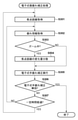
以下に、本発明の第1の実施形態について説明する。第1の実施形態では、図3を参照して、電子式像振れ補正制御部123の揺り戻し調整部206で行われる揺り戻し処理について詳しく説明する。なお、以下に説明する処理は、第2のモードまたは第3のモードが選択されて、電子式像振れ補正が行われる場合に実施される。
<First Embodiment>
The first embodiment of the present invention will be described below. In the first embodiment, the swing-back process performed by the swing-
電子式像振れ補正処理が開始すると、まず、S301ではレンズユニット100の焦点距離を取得する。上述したようにレンズユニット100との通信は一定時間ごとにしか行われないため、ここで得られるレンズユニット100の焦点距離は、次の焦点距離が取得されるまでの間、以下に説明する揺り戻し処理において用いられることになる。次に、S302において、カメラ振れ検出部122及びベクトル検出部126で検出し、計算したカメラの振れ情報を取得する。
When the electronic image shake correction process starts, first, the focal length of the
次に、S303において、S301で取得した焦点距離の履歴から、ズーム中かどうかを判定する。ズーム中であれば、S304において、非ズーム時の揺り戻し量Δθに係数k(k>1)をかけて、揺り戻し量を大きくする(Δθ×k)。ズーム中でなければ、揺り戻し量を変更せずに直接S305に進む。このように、ズーム中の場合はS304で揺り戻し量を変更した上で、S305において振れ補正と揺り戻し処理を同時に行う。最後にS306において、電子式像振れ補正を終了するかどうかを判断し、終了であれば、電子式像振れ補正処理を終了し、終了でなければ、S307において、前回レンズユニット100と通信を行ってから一定時間が経過したか判断する。経過していなければ、レンズユニット100との通信は行われないため、S302の処理から繰り返すことで、電子式手振れ補正を継続する。一方、経過していれば、S301に戻って、レンズユニット100から新たに焦点距離を取得し、上述した処理を繰り返す。
Next, in S303, it is determined whether or not zooming is in progress from the history of the focal length acquired in S301. During zooming, in S304, the swing-back amount Δθ during non-zoom is multiplied by a coefficient k (k> 1) to increase the swing-back amount (Δθ × k). If it is not zooming, proceed directly to S305 without changing the amount of swing back. In this way, in the case of zooming, after changing the swing-back amount in S304, the shake-back correction and the swing-back process are performed at the same time in S305. Finally, in S306, it is determined whether or not to end the electronic image shake correction, and if it is finished, the electronic image shake correction process is finished. If not, in S307, the previous communication with the
次に、図4を参照して、第1の実施形態の効果について説明する。図4(a)は、ズームアウト時(焦点距離が徐々に短くなる場合)の画像の切り出し位置の変化を表すグラフであり、一例として、5フレームごとにレンズユニット100と通信を行って焦点距離を更新する場合について示している。グラフ401は、従来の方法で揺り戻し処理を行った場合の撮像素子のセンサ面中心から画像切り出し位置までの距離を示している。また、グラフ402は、第1の実施形態における方法で揺り戻し処理を行った場合のセンサ面中心から画像切り出し位置までの距離を示している。ここでは、一例として、揺り戻し量Δθにかける係数kを2としている。
Next, the effect of the first embodiment will be described with reference to FIG. FIG. 4A is a graph showing a change in the cropping position of an image at the time of zooming out (when the focal length is gradually shortened). As an example, the focal length is communicated with the
図4(b)は、ズームイン時の(焦点距離が徐々に長くなる場合)の画像の切り出し位置の変化を表すグラフであり、図4(a)と同様に、5フレームごとに焦点距離を更新する場合について示している。グラフ411は、従来の方法で揺り戻し処理を行った場合の画像切り出し位置を示しており、グラフ412は、第1の実施形態における方法で揺り戻し処理を行った場合の画像切り出し位置を示している。一例として、揺り戻し量Δθにかける係数kを2としている。
FIG. 4B is a graph showing a change in the cropping position of the image when zooming in (when the focal length gradually increases), and the focal length is updated every 5 frames as in FIG. 4A. It shows the case of doing.
図4(a)及び(b)から分かるように、ズーム時に第1の実施形態の揺り戻し処理を行った場合に、5フレームごとに起こる変化が、従来例による変化よりも目立たなくなる。 As can be seen from FIGS. 4A and 4B, when the swing-back processing of the first embodiment is performed at the time of zooming, the change occurring every 5 frames becomes less noticeable than the change according to the conventional example.
上記の通り本第1の実施形態によれば、ズームが行われている場合に、ズームが行われていない場合よりも揺り戻し量を大きく設定することで、動画における不自然な動きを抑制することができる。 As described above, according to the first embodiment, when zooming is performed, the amount of swinging back is set to be larger than that when zooming is not performed, thereby suppressing unnatural movement in the moving image. be able to.
<第2の実施形態>
次に、本発明の第2の実施形態について説明する。第2の実施形態は、第1の実施形態と比較して、揺り戻し量の変更の仕方が異なる。第1の実施形態では、非ズーム時の揺り戻し量Δθに1より大きい所定の係数kをかけて、ズーム時の揺り戻し量を変更していた。これに対し、第2の実施形態では、ズーム時に、図3のS304において、ズームの速度(焦点距離の変化量)、通信間隔に応じてズーム時の係数kを変更することにより、揺り戻し量を変更する。この点以外は、第1の実施形態と同様であるため、説明を省略する。
<Second embodiment>
Next, a second embodiment of the present invention will be described. The second embodiment is different from the first embodiment in the method of changing the swing-back amount. In the first embodiment, the swing-back amount Δθ during non-zoom is multiplied by a predetermined coefficient k larger than 1, and the swing-back amount during zooming is changed. On the other hand, in the second embodiment, at the time of zooming, in S304 of FIG. 3, the swing-back amount is changed by changing the zoom speed (change amount of focal length) and the coefficient k at the time of zooming according to the communication interval. To change. Other than this point, since it is the same as that of the first embodiment, the description thereof will be omitted.
第2の実施形態では、S304において、S301で得られた焦点距離情報から、ズームの速度、通信間隔を計算し、計算した値に基づいて、揺り戻し量にかける係数kを変更する。レンズとの通信間隔が長い場合やズーム速度が速い場合(焦点距離の変化量が大きい場合)は、レンズ通信で焦点距離が更新される際の変化量が大きくなる。そのため、通信間隔が短い場合やズーム速度が遅い場合(焦点距離の変化量が小さい場合)よりも、これを目立たなくするために係数kをより大きな値にする。 In the second embodiment, in S304, the zoom speed and the communication interval are calculated from the focal length information obtained in S301, and the coefficient k to be applied to the swing-back amount is changed based on the calculated values. When the communication interval with the lens is long or the zoom speed is fast (when the amount of change in the focal length is large), the amount of change when the focal length is updated by lens communication becomes large. Therefore, the coefficient k is set to a larger value in order to make it inconspicuous than when the communication interval is short or the zoom speed is slow (when the amount of change in the focal length is small).
上記の通り本第2の実施形態によれば、ズームの速度、通信間隔に応じて、揺り戻し処理における動画の不自然な動きを更に適切に抑制することができる。 As described above, according to the second embodiment, it is possible to more appropriately suppress the unnatural movement of the moving image in the swing-back process according to the zoom speed and the communication interval.
<第3の実施形態>
次に、本発明の第3の実施形態について説明する。第3の実施形態は、第1及び第2の実施形態と比較して、揺り戻し量の変更の仕方が異なる。第1及び第2の実施形態では、非ズーム時の揺り戻し量Δθに係数kをかけて、ズーム時の揺り戻し量を変更していた。これに対し、第3の実施形態では、ズーム時に、レンズ通信で焦点距離が更新された時の変化量を、次のレンズ通信までのフレームに分散して各時間帯の焦点距離を決定する。
<Third embodiment>
Next, a third embodiment of the present invention will be described. The third embodiment is different from the first and second embodiments in the method of changing the swing-back amount. In the first and second embodiments, the swing-back amount Δθ during non-zoom is multiplied by a coefficient k to change the swing-back amount during zooming. On the other hand, in the third embodiment, at the time of zooming, the amount of change when the focal length is updated by the lens communication is dispersed in the frame until the next lens communication to determine the focal length in each time zone.
図5は、第3の実施形態における電子式像振れ補正制御部123の揺り戻し調整部206で行われる揺り戻し処理を示すフローチャートである。図5において、図3と同様の処理には同じ参照番号を付して、説明を省略する。
FIG. 5 is a flowchart showing a swing-back process performed by the swing-
第3の実施形態では、S504において、前回取得した焦点距離と今回取得した焦点距離間の変化量Δfを通信間隔に相当するフレーム数で割った値を、今回取得した焦点距離から減算(ズームアウト時)または加算(ズームイン時)する。図6は、揺り戻し処理に用いる焦点距離を示す図で、グラフ601は従来の方法で用いられる焦点距離を、グラフ602は第3の実施形態で用いられる焦点距離を示している。
In the third embodiment, in S504, the value obtained by dividing the change amount Δf between the focal length acquired last time and the focal length acquired this time by the number of frames corresponding to the communication interval is subtracted (zoom out) from the focal length acquired this time. Hour) or add (when zooming in). FIG. 6 is a diagram showing the focal length used for the swing-back process, in which
グラフ601はレンズ通信が行われた際に、焦点距離は大幅に変化してしまう。これに対し、グラフ602では、上述したように、レンズ通信を行った際の焦点距離の変化量を、次にレンズ通信するまでのフレームで分散させる。例えば、5フレーム目で取得した焦点距離が、先に取得した焦点距離と比較して25mm異なるものとする。この場合、5フレーム間で分散させるため、現在の焦点距離をfpとすると、iフレーム目の焦点距離fをfp[mm]+5[mm]×i[フレーム]とする。
In the
図6から分かるように、焦点距離は連続的に変化していくので、画像切り出し位置の変化も連続的になり、動画における不自然な動きを生じなくすることができる。 As can be seen from FIG. 6, since the focal length changes continuously, the change in the image cropping position also becomes continuous, and it is possible to prevent unnatural movement in the moving image.
以上、本発明の好ましい実施形態について説明したが、本発明はこれらの実施形態に限定されず、その要旨の範囲内で種々の変形及び変更が可能である。 Although the preferred embodiments of the present invention have been described above, the present invention is not limited to these embodiments, and various modifications and modifications can be made within the scope of the gist thereof.
<他の実施形態>
また、本発明は、上述の実施形態の1以上の機能を実現するプログラムを、ネットワーク又は記憶媒体を介してシステム又は装置に供給し、そのシステム又は装置のコンピュータにおける1つ以上のプロセッサーがプログラムを読出し実行する処理でも実現可能である。また、1以上の機能を実現する回路(例えば、ASIC)によっても実現可能である。
<Other embodiments>
The present invention also supplies a program that realizes one or more functions of the above-described embodiment to a system or device via a network or storage medium, and one or more processors in the computer of the system or device provide the program. It can also be realized by the process of reading and executing. It can also be realized by a circuit (for example, ASIC) that realizes one or more functions.
100:レンズユニット、101:ズームユニット、102:ズーム駆動制御部、112:レンズ通信制御部、115:撮像部、116:撮像信号処理部、117:映像信号処理部、119:記憶部、121:カメラ操作部、122:カメラ振れ検出部、123:電子式像振れ補正制御部、124:カメラシステム制御部、125:カメラ通信制御部、126:ベクトル検出部、200:カメラ本体、206:揺り戻し調整部、208:Pixel変換部、209:電子像振れ補正部 100: Lens unit, 101: Zoom unit, 102: Zoom drive control unit, 112: Lens communication control unit, 115: Imaging unit, 116: Imaging signal processing unit, 117: Video signal processing unit, 119: Storage unit, 121: Camera operation unit, 122: camera shake detection unit, 123: electronic image shake correction control unit, 124: camera system control unit, 125: camera communication control unit, 126: vector detection unit, 200: camera body, 206: swing back Adjustment unit, 208: Pixel conversion unit, 209: Electronic image shake correction unit
Claims (12)
前記切り出し位置を、予め決められた戻し量ずつ、前記画像の中心に向けて移動するように、前記振れ補正手段を制御する制御手段と、
前記レンズユニットから予め決められた時間間隔で得られた焦点距離に基づいて、光学ズームによるズーム動作が行われているかどうかを判断する判断手段と、を有し、
前記制御手段は、ズーム動作が行われている場合に、ズーム動作が行われていない場合よりも、前記戻し量を大きくすることを特徴とする像振れ補正装置。 A cutout position for cutting out a part of an image obtained by photoelectric conversion of an image formed through a detachable lens unit by an image sensor based on the amount of runout detected by the shake detection means. A runout correction means that corrects runout by changing the
A control means for controlling the runout correction means so that the cutout position is moved toward the center of the image by a predetermined return amount.
It has a determination means for determining whether or not a zoom operation by optical zoom is performed based on a focal length obtained from the lens unit at a predetermined time interval.
The control means is an image shake correction device characterized in that when the zoom operation is performed, the return amount is larger than when the zoom operation is not performed.
δ=θ×f
で表した場合に、前記戻し量は、予め決められた期間における前記角度θの変化量であることを特徴とする請求項1に記載の像振れ補正装置。 The distance between the center of the image and the center of the cutout position on the sensor surface of the image sensor is δ, the focal length is f, and the sensor of the image sensor corresponding to the center of the cutout position. Let θ be the angle [rad] of the position of the surface from the central axis orthogonal to the sensor surface.
δ = θ × f
The image shake correction device according to claim 1, wherein the return amount is a change amount of the angle θ in a predetermined period.
前記切り出し位置を、予め決められた戻し量ずつ、前記画像の中心に向けて移動するように、前記振れ補正手段を制御する制御手段と、
前記レンズユニットから予め決められた時間間隔で得られた焦点距離に基づいて、光学ズームによるズーム動作が行われているかどうかを判断する判断手段と、を有し、
前記画像の中心と前記切り出し位置の中心とにそれぞれ対応する、前記撮像素子のセンサ面における位置の間の距離をδ、前記焦点距離をf、画像切り出し位置の、前記センサ面と直交する中心軸からの角度[rad]をθとして、
δ=θ×f
で表され、予め決められた期間における前記角度θの変化量が一定である場合に、前記制御手段は、ズーム動作が行われていれば、前記予め決められた期間における前記焦点距離の変化量が一定となるように、前記予め決められた時間間隔で得られた焦点距離の差を分散することを特徴とする像振れ補正装置。 A cutout position for cutting out a part of an image obtained by photoelectric conversion of an image formed through a detachable lens unit by an image sensor based on the amount of runout detected by the shake detection means. A runout correction means that corrects runout by changing the
A control means for controlling the runout correction means so that the cutout position is moved toward the center of the image by a predetermined return amount.
It has a determination means for determining whether or not a zoom operation by optical zoom is performed based on a focal length obtained from the lens unit at a predetermined time interval.
The distance between the center of the image and the center of the cutout position on the sensor surface of the image sensor is δ, the focal length is f, and the central axis of the image cutout position orthogonal to the sensor surface. Let θ be the angle [rad] from
δ = θ × f
When the amount of change in the angle θ is constant in a predetermined period, the control means has the amount of change in the focal length in the predetermined period if the zoom operation is performed. An image shake correction device, characterized in that the difference in focal lengths obtained at predetermined time intervals is dispersed so that
請求項1乃至6のいずれか1項に記載の像振れ補正装置と、を有し、
前記レンズユニットを着脱可能であることを特徴とする撮像装置。 Image sensor and
The image shake correction device according to any one of claims 1 to 6 is provided.
An imaging device characterized in that the lens unit can be attached and detached.
前記撮像装置に着脱可能なレンズユニットと
を有することを特徴とする撮像システム。 The image pickup apparatus according to claim 7 and
An imaging system characterized by having a detachable lens unit in the imaging device.
制御手段が、前記切り出し位置を、予め決められた戻し量ずつ、前記画像の中心に向けて移動するように、前記振れ補正手段を制御する制御工程と、
判断手段が、前記レンズユニットから予め決められた時間間隔で得られた焦点距離に基づいて、光学ズームによるズーム動作が行われているかどうかを判断する判断工程と、を有し、
前記制御工程では、ズーム動作が行われている場合に、ズーム動作が行われていない場合よりも、前記戻し量を大きくすることを特徴とする像振れ補正方法。 A part of the light image formed by the shake correction means passing through the removable lens unit is photoelectrically converted by an image sensor based on the amount of runout detected by the shake detection means. A shake correction process that corrects runout by changing the cutout position to cut out the image,
A control step of controlling the runout correction means so that the control means moves the cutout position toward the center of the image by a predetermined return amount.
The determination means includes a determination step of determining whether or not a zoom operation by optical zoom is performed based on a focal length obtained from the lens unit at a predetermined time interval.
The image shake correction method, characterized in that, in the control step, when the zoom operation is performed, the return amount is made larger than when the zoom operation is not performed.
制御手段が、前記切り出し位置を、予め決められた戻し量ずつ、前記画像の中心に向けて移動するように、前記振れ補正手段を制御する制御工程と、
判断手段が、前記レンズユニットから予め決められた時間間隔で得られた焦点距離に基づいて、光学ズームによるズーム動作が行われているかどうかを判断する判断工程と、を有し、
前記画像の中心と前記切り出し位置の中心とにそれぞれ対応する、前記撮像素子のセンサ面における位置の間の距離をδ、前記焦点距離をf、画像切り出し位置の、前記センサ面と直交する中心軸からの角度[rad]をθとして、
δ=θ×f
で表され、予め決められた期間における前記角度θの変化量が一定である場合に、前記制御手段は、ズーム動作が行われていれば、前記予め決められた期間における前記焦点距離の変化量が一定となるように、前記予め決められた時間間隔で得られた焦点距離の差を分散することを特徴とする像振れ補正方法。 A part of the light image formed by the shake correction means passing through the removable lens unit is photoelectrically converted by an image sensor based on the amount of runout detected by the shake detection means. A shake correction process that corrects runout by changing the cutout position to cut out the image,
A control step of controlling the runout correction means so that the control means moves the cutout position toward the center of the image by a predetermined return amount.
The determination means includes a determination step of determining whether or not a zoom operation by optical zoom is performed based on a focal length obtained from the lens unit at a predetermined time interval.
The distance between the center of the image and the center of the cutout position on the sensor surface of the image sensor is δ, the focal length is f, and the central axis of the image cutout position orthogonal to the sensor surface. Let θ be the angle [rad] from
δ = θ × f
When the amount of change in the angle θ is constant in a predetermined period, the control means has the amount of change in the focal length in the predetermined period if the zoom operation is performed. A method for correcting image shake, which comprises dispersing the difference in focal length obtained at a predetermined time interval so that
Priority Applications (3)
| Application Number | Priority Date | Filing Date | Title |
|---|---|---|---|
| JP2017086546A JP6990985B2 (en) | 2017-04-25 | 2017-04-25 | Image shake correction device and method, image pickup device and image pickup system |
| US15/958,041 US10554891B2 (en) | 2017-04-25 | 2018-04-20 | Image stabilization apparatus, image stabilization method, image capturing apparatus, image capturing system and non-transitory storage medium |
| CN201810380508.7A CN108737698B (en) | 2017-04-25 | 2018-04-25 | Image stabilization apparatus and method, image pickup apparatus, image pickup system, and storage medium |
Applications Claiming Priority (1)
| Application Number | Priority Date | Filing Date | Title |
|---|---|---|---|
| JP2017086546A JP6990985B2 (en) | 2017-04-25 | 2017-04-25 | Image shake correction device and method, image pickup device and image pickup system |
Publications (3)
| Publication Number | Publication Date |
|---|---|
| JP2018185407A JP2018185407A (en) | 2018-11-22 |
| JP2018185407A5 JP2018185407A5 (en) | 2020-05-14 |
| JP6990985B2 true JP6990985B2 (en) | 2022-01-12 |
Family
ID=63854330
Family Applications (1)
| Application Number | Title | Priority Date | Filing Date |
|---|---|---|---|
| JP2017086546A Active JP6990985B2 (en) | 2017-04-25 | 2017-04-25 | Image shake correction device and method, image pickup device and image pickup system |
Country Status (3)
| Country | Link |
|---|---|
| US (1) | US10554891B2 (en) |
| JP (1) | JP6990985B2 (en) |
| CN (1) | CN108737698B (en) |
Families Citing this family (3)
| Publication number | Priority date | Publication date | Assignee | Title |
|---|---|---|---|---|
| JP6823189B2 (en) * | 2017-09-28 | 2021-01-27 | 富士フイルム株式会社 | Imaging device, its operating method and operating program |
| JP2019216374A (en) * | 2018-06-13 | 2019-12-19 | キヤノン株式会社 | Imaging apparatus and control method therefor |
| JP7301531B2 (en) * | 2018-12-04 | 2023-07-03 | キヤノン株式会社 | CONTROL DEVICE, IMAGING DEVICE, LENS DEVICE, AND CONTROL METHOD |
Citations (6)
| Publication number | Priority date | Publication date | Assignee | Title |
|---|---|---|---|---|
| CN1744674A (en) | 2005-10-09 | 2006-03-08 | 北京中星微电子有限公司 | Video electronic flutter-proof method |
| JP2006259327A (en) | 2005-03-17 | 2006-09-28 | Matsushita Electric Ind Co Ltd | Imaging apparatus |
| US20110176015A1 (en) | 2010-01-19 | 2011-07-21 | Samsung Electronics Co., Ltd. | Method and apparatus for processing digital image |
| JP2012114809A (en) | 2010-11-26 | 2012-06-14 | Sanyo Electric Co Ltd | Imaging apparatus and electronic apparatus |
| JP2013130836A5 (en) | 2011-12-22 | 2015-01-15 | Anti-vibration control device, anti-vibration control method, optical device, imaging device | |
| JP2015210287A (en) | 2014-04-23 | 2015-11-24 | キヤノン株式会社 | Imaging apparatus and control method of the same, program, storage medium |
Family Cites Families (16)
| Publication number | Priority date | Publication date | Assignee | Title |
|---|---|---|---|---|
| DE69426314T2 (en) * | 1993-02-12 | 2001-04-12 | Sony Corp | Electronic zoom control and image stabilization |
| JP2002182260A (en) * | 2000-12-11 | 2002-06-26 | Hitachi Ltd | Imaging device |
| JP5274130B2 (en) * | 2008-07-15 | 2013-08-28 | キヤノン株式会社 | Image blur correction apparatus, optical apparatus, image pickup apparatus, and image blur correction apparatus control method |
| JP5477897B2 (en) | 2009-09-28 | 2014-04-23 | 京セラ株式会社 | Image motion correction apparatus and method, and imaging apparatus |
| JP5653636B2 (en) * | 2010-02-26 | 2015-01-14 | オリンパスイメージング株式会社 | Focus control device |
| JP5917133B2 (en) | 2011-12-22 | 2016-05-11 | キヤノン株式会社 | Anti-vibration control device, anti-vibration control method, optical device, imaging device |
| JP6083972B2 (en) * | 2012-07-28 | 2017-02-22 | キヤノン株式会社 | Imaging device |
| JP6150655B2 (en) * | 2013-08-01 | 2017-06-21 | キヤノン株式会社 | Image shake correction apparatus and control method therefor, lens barrel, optical apparatus, and imaging apparatus |
| JP2016035543A (en) * | 2014-08-04 | 2016-03-17 | オリンパス株式会社 | Imaging device and method for correcting image blur using the device |
| JP6506517B2 (en) * | 2014-08-25 | 2019-04-24 | キヤノン株式会社 | Image processing apparatus, control method therefor, and imaging apparatus |
| JP6362556B2 (en) * | 2015-02-26 | 2018-07-25 | キヤノン株式会社 | Control device, imaging device, control method, program, and storage medium |
| JP6614810B2 (en) * | 2015-05-29 | 2019-12-04 | キヤノン株式会社 | Blur correction device, imaging device, and blur correction method |
| JP6562773B2 (en) * | 2015-08-26 | 2019-08-21 | キヤノン株式会社 | Imaging apparatus, control method therefor, program, and storage medium |
| US10659676B2 (en) * | 2015-12-08 | 2020-05-19 | Canon Kabushiki Kaisha | Method and apparatus for tracking a moving subject image based on reliability of the tracking state |
| JP6682336B2 (en) * | 2016-04-20 | 2020-04-15 | オリンパス株式会社 | Camera system and camera body |
| TWI672628B (en) * | 2016-12-08 | 2019-09-21 | 日商摩如富股份有限公司 | Image processing device, method, and computer readable recording medium |
-
2017
- 2017-04-25 JP JP2017086546A patent/JP6990985B2/en active Active
-
2018
- 2018-04-20 US US15/958,041 patent/US10554891B2/en active Active
- 2018-04-25 CN CN201810380508.7A patent/CN108737698B/en active Active
Patent Citations (6)
| Publication number | Priority date | Publication date | Assignee | Title |
|---|---|---|---|---|
| JP2006259327A (en) | 2005-03-17 | 2006-09-28 | Matsushita Electric Ind Co Ltd | Imaging apparatus |
| CN1744674A (en) | 2005-10-09 | 2006-03-08 | 北京中星微电子有限公司 | Video electronic flutter-proof method |
| US20110176015A1 (en) | 2010-01-19 | 2011-07-21 | Samsung Electronics Co., Ltd. | Method and apparatus for processing digital image |
| JP2012114809A (en) | 2010-11-26 | 2012-06-14 | Sanyo Electric Co Ltd | Imaging apparatus and electronic apparatus |
| JP2013130836A5 (en) | 2011-12-22 | 2015-01-15 | Anti-vibration control device, anti-vibration control method, optical device, imaging device | |
| JP2015210287A (en) | 2014-04-23 | 2015-11-24 | キヤノン株式会社 | Imaging apparatus and control method of the same, program, storage medium |
Also Published As
| Publication number | Publication date |
|---|---|
| JP2018185407A (en) | 2018-11-22 |
| US10554891B2 (en) | 2020-02-04 |
| US20180309932A1 (en) | 2018-10-25 |
| CN108737698B (en) | 2021-02-02 |
| CN108737698A (en) | 2018-11-02 |
Similar Documents
| Publication | Publication Date | Title |
|---|---|---|
| EP2187626B1 (en) | Image pickup apparatus and control method thereof | |
| JP7277513B2 (en) | a lens device, a lens device control method, and a lens device control program; | |
| JP6530602B2 (en) | Image pickup apparatus and control method thereof | |
| JP6808399B2 (en) | Accessory device, control device, imaging system, communication control method and communication control program | |
| JP2017152996A (en) | Imaging system, method for controlling the same, imaging apparatus, and lens device | |
| JP6543946B2 (en) | Shake correction device, camera and electronic device | |
| JP6429500B2 (en) | Optical apparatus, interchangeable lens, and image blur correction method | |
| JP2015130612A (en) | Imaging apparatus and control method of the same | |
| JP2005215388A (en) | Interchangeable lens and camera system using the same | |
| JP6990985B2 (en) | Image shake correction device and method, image pickup device and image pickup system | |
| JP2017219635A (en) | Image processing device and method, imaging device, and imaging system | |
| JP2016080918A (en) | Image shake correction device and control method therefor | |
| US9635266B2 (en) | Image stabilization apparatus and control method thereof, and storage medium | |
| JP2020076897A (en) | Imaging system, control method of the same, lens unit, imaging apparatus, program, and storage medium | |
| JP5886623B2 (en) | Imaging apparatus and control method thereof | |
| JP7071204B2 (en) | Imaging system, lens device, imaging device, and its control method | |
| JP7395552B2 (en) | Control device, imaging device, lens device, control method, and program | |
| JP6702737B2 (en) | Image blur correction apparatus and method for controlling image blur correction apparatus | |
| JP6611585B2 (en) | Zoom control device, zoom control method, and imaging device | |
| JP6943323B2 (en) | interchangeable lens | |
| JP6465553B2 (en) | Imaging apparatus and control method thereof | |
| JP2011154104A (en) | View angle center deviation correction device and view angle deviation correction method | |
| JP6778014B2 (en) | Imaging device and its control method, program, storage medium | |
| JP2015118147A (en) | Imaging apparatus and control method thereof | |
| JP2021026081A (en) | Lens device, imaging apparatus, imaging system, method for controlling these, program, and recording medium |
Legal Events
| Date | Code | Title | Description |
|---|---|---|---|
| A521 | Request for written amendment filed |
Free format text: JAPANESE INTERMEDIATE CODE: A523 Effective date: 20200401 |
|
| A621 | Written request for application examination |
Free format text: JAPANESE INTERMEDIATE CODE: A621 Effective date: 20200401 |
|
| RD01 | Notification of change of attorney |
Free format text: JAPANESE INTERMEDIATE CODE: A7421 Effective date: 20210103 |
|
| A521 | Request for written amendment filed |
Free format text: JAPANESE INTERMEDIATE CODE: A523 Effective date: 20210113 |
|
| A977 | Report on retrieval |
Free format text: JAPANESE INTERMEDIATE CODE: A971007 Effective date: 20210222 |
|
| A131 | Notification of reasons for refusal |
Free format text: JAPANESE INTERMEDIATE CODE: A131 Effective date: 20210319 |
|
| A521 | Request for written amendment filed |
Free format text: JAPANESE INTERMEDIATE CODE: A523 Effective date: 20210517 |
|
| TRDD | Decision of grant or rejection written | ||
| A01 | Written decision to grant a patent or to grant a registration (utility model) |
Free format text: JAPANESE INTERMEDIATE CODE: A01 Effective date: 20211108 |
|
| A61 | First payment of annual fees (during grant procedure) |
Free format text: JAPANESE INTERMEDIATE CODE: A61 Effective date: 20211207 |
|
| R151 | Written notification of patent or utility model registration |
Ref document number: 6990985 Country of ref document: JP Free format text: JAPANESE INTERMEDIATE CODE: R151 |