JP6990567B2 - Door pinch detection device and door opening / closing device - Google Patents
Door pinch detection device and door opening / closing device Download PDFInfo
- Publication number
- JP6990567B2 JP6990567B2 JP2017224882A JP2017224882A JP6990567B2 JP 6990567 B2 JP6990567 B2 JP 6990567B2 JP 2017224882 A JP2017224882 A JP 2017224882A JP 2017224882 A JP2017224882 A JP 2017224882A JP 6990567 B2 JP6990567 B2 JP 6990567B2
- Authority
- JP
- Japan
- Prior art keywords
- door
- vehicle
- state
- detection
- detection signal
- Prior art date
- Legal status (The legal status is an assumption and is not a legal conclusion. Google has not performed a legal analysis and makes no representation as to the accuracy of the status listed.)
- Active
Links
Images


Classifications
-
- E—FIXED CONSTRUCTIONS
- E05—LOCKS; KEYS; WINDOW OR DOOR FITTINGS; SAFES
- E05F—DEVICES FOR MOVING WINGS INTO OPEN OR CLOSED POSITION; CHECKS FOR WINGS; WING FITTINGS NOT OTHERWISE PROVIDED FOR, CONCERNED WITH THE FUNCTIONING OF THE WING
- E05F15/00—Power-operated mechanisms for wings
- E05F15/40—Safety devices, e.g. detection of obstructions or end positions
- E05F15/42—Detection using safety edges
- E05F15/47—Detection using safety edges responsive to changes in fluid pressure
-
- E—FIXED CONSTRUCTIONS
- E05—LOCKS; KEYS; WINDOW OR DOOR FITTINGS; SAFES
- E05Y—INDEXING SCHEME RELATING TO HINGES OR OTHER SUSPENSION DEVICES FOR DOORS, WINDOWS OR WINGS AND DEVICES FOR MOVING WINGS INTO OPEN OR CLOSED POSITION, CHECKS FOR WINGS AND WING FITTINGS NOT OTHERWISE PROVIDED FOR, CONCERNED WITH THE FUNCTIONING OF THE WING
- E05Y2400/00—Electronic control; Power supply; Power or signal transmission; User interfaces
- E05Y2400/10—Electronic control
- E05Y2400/44—Sensors therefore
-
- E—FIXED CONSTRUCTIONS
- E05—LOCKS; KEYS; WINDOW OR DOOR FITTINGS; SAFES
- E05Y—INDEXING SCHEME RELATING TO HINGES OR OTHER SUSPENSION DEVICES FOR DOORS, WINDOWS OR WINGS AND DEVICES FOR MOVING WINGS INTO OPEN OR CLOSED POSITION, CHECKS FOR WINGS AND WING FITTINGS NOT OTHERWISE PROVIDED FOR, CONCERNED WITH THE FUNCTIONING OF THE WING
- E05Y2400/00—Electronic control; Power supply; Power or signal transmission; User interfaces
- E05Y2400/10—Electronic control
- E05Y2400/50—Fault detection
- E05Y2400/508—Fault detection of detection
-
- E—FIXED CONSTRUCTIONS
- E05—LOCKS; KEYS; WINDOW OR DOOR FITTINGS; SAFES
- E05Y—INDEXING SCHEME RELATING TO HINGES OR OTHER SUSPENSION DEVICES FOR DOORS, WINDOWS OR WINGS AND DEVICES FOR MOVING WINGS INTO OPEN OR CLOSED POSITION, CHECKS FOR WINGS AND WING FITTINGS NOT OTHERWISE PROVIDED FOR, CONCERNED WITH THE FUNCTIONING OF THE WING
- E05Y2400/00—Electronic control; Power supply; Power or signal transmission; User interfaces
- E05Y2400/10—Electronic control
- E05Y2400/52—Safety arrangements
- E05Y2400/53—Wing impact prevention or reduction
- E05Y2400/54—Obstruction or resistance detection
-
- E—FIXED CONSTRUCTIONS
- E05—LOCKS; KEYS; WINDOW OR DOOR FITTINGS; SAFES
- E05Y—INDEXING SCHEME RELATING TO HINGES OR OTHER SUSPENSION DEVICES FOR DOORS, WINDOWS OR WINGS AND DEVICES FOR MOVING WINGS INTO OPEN OR CLOSED POSITION, CHECKS FOR WINGS AND WING FITTINGS NOT OTHERWISE PROVIDED FOR, CONCERNED WITH THE FUNCTIONING OF THE WING
- E05Y2900/00—Application of doors, windows, wings or fittings thereof
- E05Y2900/50—Application of doors, windows, wings or fittings thereof for vehicles
- E05Y2900/506—Application of doors, windows, wings or fittings thereof for vehicles for buses
-
- E—FIXED CONSTRUCTIONS
- E05—LOCKS; KEYS; WINDOW OR DOOR FITTINGS; SAFES
- E05Y—INDEXING SCHEME RELATING TO HINGES OR OTHER SUSPENSION DEVICES FOR DOORS, WINDOWS OR WINGS AND DEVICES FOR MOVING WINGS INTO OPEN OR CLOSED POSITION, CHECKS FOR WINGS AND WING FITTINGS NOT OTHERWISE PROVIDED FOR, CONCERNED WITH THE FUNCTIONING OF THE WING
- E05Y2900/00—Application of doors, windows, wings or fittings thereof
- E05Y2900/50—Application of doors, windows, wings or fittings thereof for vehicles
- E05Y2900/51—Application of doors, windows, wings or fittings thereof for vehicles for railway cars or mass transit vehicles
-
- E—FIXED CONSTRUCTIONS
- E05—LOCKS; KEYS; WINDOW OR DOOR FITTINGS; SAFES
- E05Y—INDEXING SCHEME RELATING TO HINGES OR OTHER SUSPENSION DEVICES FOR DOORS, WINDOWS OR WINGS AND DEVICES FOR MOVING WINGS INTO OPEN OR CLOSED POSITION, CHECKS FOR WINGS AND WING FITTINGS NOT OTHERWISE PROVIDED FOR, CONCERNED WITH THE FUNCTIONING OF THE WING
- E05Y2900/00—Application of doors, windows, wings or fittings thereof
- E05Y2900/50—Application of doors, windows, wings or fittings thereof for vehicles
- E05Y2900/53—Application of doors, windows, wings or fittings thereof for vehicles characterised by the type of wing
- E05Y2900/531—Doors
Description
本発明は、車両の乗降口を開閉するドアの戸挟み検知装置及びドア開閉装置に関する。 The present invention relates to a door pinch detection device and a door opening / closing device for doors that open / close the entrance / exit of a vehicle.
車両の乗降口を開閉するドアによって、物が挟まれる戸挟みを検知する戸挟み検知装置が提案されている(例えば、特許文献1参照)。
特許文献1に記載の戸挟み検知装置では、ドアの戸先に取り付けられる弾性部材の変形を圧力スイッチが設けられている。そして、圧力スイッチの結果に基づいて戸挟みを検知している。
A door pinch detection device has been proposed that detects a door pinch in which an object is pinched by a door that opens and closes an entrance / exit of a vehicle (see, for example, Patent Document 1).
In the door pinch detection device described in
ところで、上記の戸挟み検知装置では、車両の走行時の振動による圧力変化が圧力スイッチに検出されると、戸挟みの検知精度が低下するおそれがある。
本発明は、こうした実情に鑑みてなされたものであり、その目的は、戸挟みの検知精度を高めることのできる戸挟み検知装置及びドア開閉装置を提供することにある。
By the way, in the above-mentioned door pinch detection device, if a pressure change due to vibration during traveling of a vehicle is detected by the pressure switch, the door pinch detection accuracy may decrease.
The present invention has been made in view of such circumstances, and an object of the present invention is to provide a door pinch detection device and a door opening / closing device capable of improving the detection accuracy of a door pinch.
上記課題を解決する戸挟み検知装置は、車両の乗降口を開閉するドアが戸挟み状態であるか否かを検知する戸挟み検知装置であって、前記ドアの戸先に取り付けられた弾性部材の変形を検知する検知センサからの出力信号を取得する取得部と、前記取得部が取得した前記出力信号に含まれる前記車両の走行による振動の影響を低減する処理を行って検知信号を生成する検知信号生成部と、前記検知信号生成部により得られた検知信号に基づいて前記ドアが戸挟み状態であるか否かを判定する判定部と、を備える。 The door pinch detection device that solves the above problems is a door pinch detection device that detects whether or not the door that opens and closes the entrance / exit of the vehicle is in the door pinch state, and is an elastic member attached to the door end of the door. The detection signal is generated by performing processing to reduce the influence of vibration caused by the running of the vehicle included in the output signal acquired by the acquisition unit and the acquisition unit that acquires the output signal from the detection sensor that detects the deformation of the vehicle. It includes a detection signal generation unit and a determination unit for determining whether or not the door is in a door-clamped state based on the detection signal obtained by the detection signal generation unit.
上記構成によれば、車両の走行による振動の影響を低減する処理を行って戸挟み状態であるか否かを判定することで、車両の振動に起因する戸挟みの誤検知を抑制することができる。その結果、戸挟みの検知精度を高めることができる。 According to the above configuration, it is possible to suppress erroneous detection of door pinching caused by vehicle vibration by performing a process of reducing the influence of vibration caused by vehicle running to determine whether or not the vehicle is in a door pinching state. can. As a result, the detection accuracy of the door pinch can be improved.
上記戸挟み検知装置について、前記検知信号生成部は、前記取得部が取得した前記出力信号から前記車両の走行に起因する振動の周波数成分を低減させた検知信号を生成する。
車両の走行時には、車両の振動の周波数成分が検知センサからの出力信号に含まれる。上記構成によれば、出力信号に含まれる車両の振動の周波数成分を低減することで、車両の振動に起因する戸挟みの誤検知を抑制することができる。ここで、「低減させた信号」とは、車両の走行に起因する振動の周波数成分を低減させた信号のみならず、走行に起因する振動の周波数以外のある特定の周波数帯域のみの信号も含むものとする。
Regarding the door pinch detection device, the detection signal generation unit generates a detection signal in which the frequency component of vibration caused by the running of the vehicle is reduced from the output signal acquired by the acquisition unit.
When the vehicle is running, the frequency component of the vibration of the vehicle is included in the output signal from the detection sensor. According to the above configuration, by reducing the frequency component of the vibration of the vehicle included in the output signal, it is possible to suppress the false detection of the door pinch caused by the vibration of the vehicle. Here, the "reduced signal" includes not only a signal in which the frequency component of vibration caused by traveling of the vehicle is reduced, but also a signal of only a specific frequency band other than the frequency of vibration caused by traveling. It shall be muted.
上記戸挟み検知装置について、前記検知信号生成部は、前記車両の走行状態に応じて、低減する周波数成分を異ならせて前記検知信号を生成することが好ましい。
車両の走行状態によって車両の振動の周波数成分が異なることがある。そこで、上記構成によれば、車両の走行状態に応じた周波数成分が低減されるため、戸挟みの検知精度を更に高めることができる。
With respect to the door pinch detection device, it is preferable that the detection signal generation unit generates the detection signal with different frequency components to be reduced according to the traveling state of the vehicle.
The frequency component of the vibration of the vehicle may differ depending on the running condition of the vehicle. Therefore, according to the above configuration, since the frequency component according to the traveling state of the vehicle is reduced, the detection accuracy of the door pinch can be further improved.
上記戸挟み検知装置について、前記判定部は、前記検知信号と判定値との比較により判定し、前記車両の走行状態に応じて異なる判定値を用いて判定することが好ましい。
車両の走行状態によって車両の振動が異なることがある。そこで、上記構成によれば、戸挟みの検知精度を更に高めることができる。
It is preferable that the determination unit determines the door pinch detection device by comparing the detection signal with the determination value and uses different determination values according to the traveling state of the vehicle.
The vibration of the vehicle may differ depending on the running condition of the vehicle. Therefore, according to the above configuration, the detection accuracy of the door pinch can be further improved.
上記戸挟み検知装置について、前記検知信号生成部は、前記取得部が所定期間内に取得した前記出力信号に含まれる所定基準を超えた出力信号の数を計数して、前記数を検知信号として生成し、前記判定部は、前記数が閾値以上であるときに戸挟み状態であると判定することが好ましい。 Regarding the door pinch detection device, the detection signal generation unit counts the number of output signals in the output signal acquired by the acquisition unit within a predetermined period and exceeds a predetermined reference, and uses the number as a detection signal. It is preferable that the determination unit determines that the door is pinched when the number is equal to or greater than the threshold value.
車両の走行時には、車両の振動を検知部材が検知する可能性がある。上記構成によれば、取得部が所定期間内に取得した出力信号に含まれる所定基準を超えた出力信号の数を計数して、前記数が閾値以上であるときに戸挟み状態であると判定することで、車両の走行による振動の検知を抑制することができる。 When the vehicle is running, the detection member may detect the vibration of the vehicle. According to the above configuration, the acquisition unit counts the number of output signals included in the output signals acquired within a predetermined period and exceeds a predetermined reference, and determines that the door is pinched when the number is equal to or greater than the threshold value. By doing so, it is possible to suppress the detection of vibration caused by the running of the vehicle.
上記戸挟み検知装置について、前記判定部は、前記車両の速度に応じて前記閾値を変更することが好ましい。
上記構成によれば、車両の速度に応じて閾値が変更されるため、戸挟みの検知精度を更に高めることができる。
Regarding the door pinch detection device, it is preferable that the determination unit changes the threshold value according to the speed of the vehicle.
According to the above configuration, since the threshold value is changed according to the speed of the vehicle, the detection accuracy of the door pinch can be further improved.
上記戸挟み検知装置について、前記判定部は、前記車両の駆動開始信号が入力したときに前記閾値を変更することが好ましい。
上記構成によれば、車両の駆動開始信号が入力したときに車両に駆動力が付与されて車両が走りだすため、車両が走行状態であると判定して戸挟みを検知することができる。
Regarding the door pinch detection device, it is preferable that the determination unit changes the threshold value when the drive start signal of the vehicle is input.
According to the above configuration, when the drive start signal of the vehicle is input, the driving force is applied to the vehicle and the vehicle starts to run. Therefore, it is possible to determine that the vehicle is in the running state and detect the door pinch.
上記戸挟み検知装置について、前記判定部は、前記車両のブレーキ解除信号が入力したときに前記閾値を変更することが好ましい。
上記構成によれば、車両のブレーキ解除信号が入力したときに車両の制動が解除されて、地形によっては車両が走行することが考えられるので、車両が走行状態であると判定して戸挟みを検知することができる。
Regarding the door pinch detection device, it is preferable that the determination unit changes the threshold value when the brake release signal of the vehicle is input.
According to the above configuration, when the brake release signal of the vehicle is input, the braking of the vehicle is released, and it is possible that the vehicle runs depending on the terrain. Can be detected.
上記戸挟み検知装置について、前記検知センサを備え前記検知センサは、前記弾性部材の内部に形成されている中空部内の圧力を検知する圧力センサであることが好ましい。
上記課題を解決するドア開閉装置は、前記ドアの開閉を制御するドア制御装置を備え、前記ドア制御装置は、前記ドアの戸先に取り付けられた弾性部材の変形を検知する検知センサからの出力信号を取得する取得部と、前記取得部が取得した前記出力信号に含まれる前記車両の走行による振動の影響を低減する処理を行って検知信号を生成する検知信号生成部と、前記検知信号生成部により得られた検知信号に基づいて前記ドアが戸挟み状態であるか否かを判定する判定部と、を備える。
The door pinch detection device is preferably provided with the detection sensor, and the detection sensor is preferably a pressure sensor that detects the pressure in the hollow portion formed inside the elastic member.
The door opening / closing device that solves the above problems includes a door control device that controls the opening / closing of the door, and the door control device outputs from a detection sensor that detects deformation of an elastic member attached to the door end of the door. An acquisition unit that acquires a signal, a detection signal generation unit that generates a detection signal by performing processing that reduces the influence of vibration due to the running of the vehicle included in the output signal acquired by the acquisition unit, and the detection signal generation unit. A determination unit for determining whether or not the door is in a door-clamped state based on a detection signal obtained by the unit is provided.
上記構成によれば、出力信号に含まれる車両の走行による振動の影響を低減する処理を行って戸挟み状態であるか否かを判定することで、車両の振動に起因する戸挟みの誤検知を抑制することができる。その結果、戸挟みの検知精度を高めることができる。 According to the above configuration, false detection of door pinching due to vehicle vibration is performed by performing a process of reducing the influence of vibration due to vehicle running included in the output signal to determine whether or not the vehicle is in a door pinching state. Can be suppressed. As a result, the detection accuracy of the door pinch can be improved.
本発明によれば、戸挟みの検知精度を高めることができる。 According to the present invention, the accuracy of detecting a door pinch can be improved.
(第1の実施形態)
以下、図1~図4を参照して、戸挟み検知装置の第1の実施形態について説明する。戸挟み検知装置は、電車等の車両の乗降口を開閉する各ドアに対して設けられ、ドアに物等が挟まれる戸挟みを検知する装置である。
(First Embodiment)
Hereinafter, the first embodiment of the door pinch detection device will be described with reference to FIGS. 1 to 4. The door pinch detection device is provided for each door that opens and closes the entrance / exit of a vehicle such as a train, and is a device that detects a door pinch in which an object or the like is caught in the door.
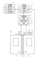
図1に示すように、車両のドア30は、図中左側の第1ドア31と図中右側の第2ドア32とを備える両開きドアである。ドア30は、空気圧シリンダの動作によって開閉される。ドア30は、ドア制御装置2によって駆動制御される。ドア制御装置2は、空気圧シリンダを制御することでドア30を開閉する。なお、ドア30の駆動装置は、空気圧シリンダに限らず、電動モータ等も駆動装置であってもよい。
As shown in FIG. 1, the
ドア30には、ドア30に物等が挟まれたことを検知する戸挟み検知装置1が設けられている。戸挟み検知装置1は、ドア制御装置2と電気的に接続され、信号を相互通信している。また、ドア制御装置2は、車両を制御する運転室等に設置される車両制御盤4と電気的に接続され、信号を相互通信している。ドア制御装置2と戸挟み検知装置1とを備える装置をドア開閉装置3とする。
The
ドア制御装置2は、ドア30の開閉の制御を行うドア開閉部21と、全閉時に減圧制御を行うドア減圧部22とを備える。ドア開閉部21は、図示しないコンプレッサの空気圧によって空気圧シリンダの駆動を制御して、ドア30を全開状態と全閉状態との間で移動させる。ドア減圧部22は、全閉状態のドア30において、全閉状態になってから所定期間のみ、空気圧シリンダの閉まる方向の駆動を弱める。これより、乗降者の物等が第1ドア31と第2ドア32との間に挟まった際に、ドア30を乗降者によって開いて戸挟みを解消することができる。なお、ドア減圧部22の構成を省略してもよい。
The
車両制御盤4は、ドア制御装置2にドア30の開閉指令を行う開閉指令部41と、戸挟みの検知を許可する検知許可部42と、戸挟みを報知する戸挟み報知部43とを備える。開閉指令部41は、運転士によって操作され、開指令又は閉指令をドア制御装置2に出力する。ドア制御装置2は、開指令が入力されると、ドア開閉部21がドア30を開状態に移動させ、閉指令が入力されると、ドア開閉部21がドア30を閉状態に移動させる。検知許可部42は、運転士によって操作され、戸挟み検知を行うときには検知指令を出力し、戸挟み検知を行わないときには検知指令を出力しない。戸挟み報知部43は、戸挟み検知装置1によって戸挟みが検知されたときに、車両制御盤4に設けられたランプを点灯させたり、戸挟みの情報を表示させたりする。
The
第1ドア31の戸先には、ゴム等の弾性材料からなる第1弾性部材51が取り付けられている。第1弾性部材51は、内部に空間51Aを有する筒状部材である。第1弾性部材51は、ドア30に物が挟まったときには変形し、空間51Aの体積が変化する。第2ドア32の戸先には、ゴム等の弾性材料からなる第2弾性部材52が取り付けられている。第2弾性部材52は、内部に空間52Aを有する筒状部材である。第2弾性部材52は、ドア30に物が挟まったときには変形し、空間52Aの体積が変化する。なお、空間51A,52Aが弾性部材の中空部に相当する。
A first
第1ドア31には、第1弾性部材51の変形を検知する第1検知センサ53が設けられている。第1検知センサ53は、第1弾性部材51の空間51Aの圧力を検知する圧力センサである。第1検知センサ53は、ドア30が閉じた状態での圧力を基準圧力として、基準圧力に対する変動圧力を出力信号として出力する。第1検知センサ53は、第1ドア31の上部に取り付けられ、第1弾性部材51の空間51Aの上端部にチューブ53Aを介して接続されている。なお、第1検知センサ53を戸挟み検知装置1の構成の一部としてもよい。また、第1検知センサ53及び第1弾性部材51を戸挟み検知装置1の構成の一部としてもよい。
The
第2ドア32には、第2弾性部材52の変形を検知する第2検知センサ54が設けられている。第2検知センサ54は、第2弾性部材52の空間52Aの圧力を検知する圧力センサである。第2検知センサ54は、ドア30が閉じた状態での圧力を基準圧力として、基準圧力に対する変動圧力を出力信号として出力する。第2検知センサ54は、第2ドア32の上部に取り付けられ、第2弾性部材52の空間52Aの上端部にチューブ54Aを介して接続されている。なお、第2検知センサ54を戸挟み検知装置1の構成の一部としてもよい。また、第2検知センサ54及び第2弾性部材52を戸挟み検知装置1の構成の一部としてもよい。
The
ドア30には、ドア30が閉じられたことを検出する戸閉スイッチ23が設けられている。戸閉スイッチ23は、ドア30が閉じられることにより第2ドア32が所定位置に達すると、車両の本体に取り付けられる接触部60に接触するように、第2ドア32に取り付けられている。接触部60に接触した戸閉スイッチ23は、ドア30が閉じたことを示す戸閉信号をドア制御装置2に出力する。戸閉信号は、ドア制御装置2を介して車両制御盤4に出力される。なお、戸閉スイッチ23は、第1ドア31に取り付けられてもよい。
The
戸挟み検知装置1は、第1検知センサ53及び第2検知センサ54からの出力信号を取得する取得部11と、判定に用いる検知信号を生成する検知信号生成部12と、戸挟みであるか否かを判定する判定部13とを備える。
Whether the door
取得部11は、第1検知センサ53から出力された第1出力信号を取得する。
検知信号生成部12は、取得部11が取得した出力信号に含まれる車両の走行による振動の影響を低減する処理を行って検知信号を生成する。すなわち、検知信号生成部12は取得部11が取得した第1出力信号をフィルタ12Aに通過させて車両の振動の周波数成分を低減させた第1検知信号を判定部13に出力する。検知信号生成部12は、フィルタ12Aを備える。フィルタ12Aは、車両の振動の周波数成分が高周波数であることが多いので、ローパスフィルタが有効である。フィルタ12Aは、例えば6Hz以上の周波数の信号を除去する。検知信号生成部12は、第2検知センサ54から出力された第2出力信号を取得し、第2出力信号をフィルタ12Aに通過させて車両の振動の周波数成分を低減させた第2検知信号を判定部13に出力する。
The
The detection
判定部13は、検知信号生成部12により得られた検知信号に基づいて戸挟み状態であるか否かを判定する。判定部13は、検知信号生成部12から入力される検知信号と判定値との比較によって戸挟み状態であるか否かを判定し、検知信号が判定値よりも大きいときに戸挟み状態であると判定する。なお、判定部13は、検知信号生成部12から入力される第1検知信号と第2検知信号との少なくとも一方が判定値よりも大きいときに戸挟み状態であると判定する。第1検知信号と第2検知信号との一方のみが判定値よりも大きいときに戸挟み状態であると判定すれば、戸挟みを早く検知することができる可能性が高くなる。また、第1検知信号と第2検知信号との両方が判定値よりも大きいときに戸挟み状態であると判定すれば、戸挟みを確実に検知することができる可能性が高くなる。
The
ここで、図2及び図3を参照して、フィルタ12Aによる車両の振動の周波数成分の低減について説明する。
図2は、検知センサ53,54から出力された出力信号を示している。図2の左側には、車両が停止状態における戸挟みが発生したときの出力信号X1を示し、低周波の信号となる。図2の右側には、車両走行時の走行振動があるときの出力信号X2を示し、高周波の信号となる。走行振動を含む出力信号X2の振幅は第1振幅W1となるため、戸挟みを判定するための判定値は第1振幅W1よりも大きな第1判定値T1とせざるを得ない。第1判定値T1では、戸挟みにおける左側の山M1を検知することができず、戸挟みにおける右側の山M2のように左側の山M1よりも大きな値でないと検知することができない。そこで、検知センサ53,54から出力された出力信号をフィルタ12Aに通過させることで、図3に示す検知信号が得られる。
Here, with reference to FIGS. 2 and 3, the reduction of the frequency component of the vibration of the vehicle by the
FIG. 2 shows the output signals output from the
図3は、出力信号をフィルタ12Aに通過させた検知信号を示している。図3の左側には、車両が停止状態における戸挟みが発生したときの検知信号Y1を示している。図3の右側には、車両走行時の走行振動があるときの検知信号Y2を示している。走行振動を含む検知信号Y2の振幅は第1振幅W1よりも小さな第2振幅W2となるため、戸挟みを判定するための判定値は第1判定値T1よりも小さな第2判定値T2とすることができる。第2判定値T2では、戸挟みにおける右側の山M2よりも小さい左側の山M1を検知することができる。
FIG. 3 shows a detection signal in which the output signal is passed through the
次に、図4を参照して、戸挟み検知装置1による戸挟み検知処理について説明する。
まず、戸挟み検知装置1は、ドア閉指令があるか否かを判定する(ステップS11)。すなわち、戸挟み検知装置1は、ドア制御装置2を介して車両制御盤4から出力されたドア閉指令の入力があると、ドア30が閉まるので戸挟みがあるか否かの検知を開始する。なお、戸挟み検知装置1は、ドア閉指令がないとき(ステップS11:NO)には、ドア閉指令があるまで待機する。
Next, with reference to FIG. 4, the door pinch detection process by the door
First, the door
一方、戸挟み検知装置1は、ドア閉指令があるとき(ステップS11:YES)には、検知信号を取得する(ステップS12)。すなわち、取得部11は、第1検知センサ53から第1出力信号が入力すると、第1出力信号をフィルタ12Aに通過させて、車両の振動の周波数成分を低減させた第1検知信号として取得する。また、取得部11は、第2検知センサ54から第2出力信号が入力すると、第2出力信号をフィルタ12Aに通過させて、車両の振動の周波数成分を低減させた第2検知信号として取得する。そして、取得部11は、第1検知信号及び第2検知信号を判定部13に出力する。
On the other hand, the door
続いて、戸挟み検知装置1は、検知信号が判定値よりも大きいか否かを判定する(ステップS13)。すなわち、判定部13は、検知信号が判定値T2以下であると判定すると(ステップS13:NO)、終了条件が成立するか否かを判定する(ステップS17)。判定部13は、終了条件が成立しない場合には(ステップS17:NO)、ステップS12に移行して処理を継続する。また、判定部13は、終了条件が成立する場合には(ステップS17:YES)、ステップS16に移行する。ここで、終了条件は、車両が走行を開始して所定時間経過した、車両後端がホーム端を通過した、車両速度が所定速度を超えた等の戸挟み検知が不要となる条件である。
Subsequently, the door
一方、判定部13は、検知信号が判定値T2よりも大きいと判定すると(ステップS13:YES)、戸挟みありと判定する(ステップS14)。すなわち、判定部13は、出
力信号に車両の走行振動が含まれていたとしても、出力信号をフィルタ12Aに通過させた検知信号に対して判定することで、出力信号に対して判定する第1判定値T1よりも小さい第2判定値T2により判定することができるようになる。
On the other hand, when the
ここで、ステップS12、ステップS13、及びステップS17の処理を言い換えると、判定部13は、検知信号を継続して取得して、判定値T2よりも大きい検知信号が存在するか終了条件が成立するまで判定を継続する。
Here, in other words, the processing of step S12, step S13, and step S17 is that the
続いて、戸挟み検知装置1は、戸挟みを出力する(ステップS15)。判定部13は、戸挟みありと判定すると、戸挟みがあることをドア制御装置2に出力し、ドア制御装置2を介して車両制御盤4に戸挟みを出力する。
Subsequently, the door
続いて、戸挟み検知装置1は、検知信号の取得を停止して(ステップS16)、戸挟み検知処理を終了する。すなわち、取得部11は、出力信号の入力自体を停止する。また、取得部11は、第1検知センサ53及び第2検知センサ54からの出力信号の出力を停止させてもよいし、第1検知センサ53及び第2検知センサ54による圧力の検知を停止させてもよい。
Subsequently, the door
上記の戸挟み検知装置1では、検知センサ53,54を用いることで、従来技術の検知スイッチによって戸挟みを判定するものと異なり、弾性部材51,52の変形による圧力変動を用いることで、車両の振動の周波数成分を低減することができる。
In the above-mentioned door
以上説明したように、本実施形態によれば、以下の効果を奏することができる。
(1)車両の走行による振動の影響を低減する処理を行って戸挟み状態であるか否かを判定することで、車両の振動に起因する戸挟みの誤検知を抑制することができる。その結果、戸挟みの検知精度を高めることができる。
As described above, according to the present embodiment, the following effects can be obtained.
(1) By performing a process of reducing the influence of vibration caused by the running of the vehicle and determining whether or not the vehicle is in a door-pinched state, it is possible to suppress erroneous detection of door-pinched due to the vibration of the vehicle. As a result, the detection accuracy of the door pinch can be improved.
(2)出力信号に含まれる車両の振動の周波数成分を低減することで、車両の振動に起因する戸挟みの誤検知を抑制することができる。
(第2の実施形態)
以下、図5を参照して、戸挟み検知装置の第2の実施形態について説明する。この実施形態の戸挟み検知装置は、車両の走行状態を加味して判定する点が上記第1の実施形態と異なっている。以下、第1の実施形態との相違点を中心に説明する。
(2) By reducing the frequency component of the vibration of the vehicle included in the output signal, it is possible to suppress the false detection of the door pinch caused by the vibration of the vehicle.
(Second embodiment)
Hereinafter, a second embodiment of the door pinch detection device will be described with reference to FIG. The door pinch detection device of this embodiment is different from the first embodiment in that the determination is made in consideration of the traveling state of the vehicle. Hereinafter, the differences from the first embodiment will be mainly described.
戸挟み検知装置1は、車両の走行状態を示す走行状態情報を車両制御盤4からドア制御装置2を介して取得する。ここで、走行状態情報とは、車両の状態である停止、走行(力行)、及び制動(ブレーキ)、や車両速度を示す情報等である。
The door
戸挟み検知装置1の検知信号生成部12のフィルタ12Aは、車両の走行状態に応じて異なる周波数成分を除去する。フィルタ12Aは、車両速度が上昇するほど、走行振動による出力信号の周波数は上昇するので、除去する周波数の下限が上昇される。また、フィルタ12Aは、車両の状態から車両速度が上昇すると考えられる場合には除去する周波数の下限が上昇され、車両の状態から車両速度が減少すると考えられる場合には除去する周波数の下限が減少される。
The
戸挟み検知装置1の判定部13は、車両の走行状態に応じて異なる判定値を用いて判定する。車両速度が上昇するほど戸挟みの可能性は減少するので、判定値が上昇される。また、車両の状態から車両速度が上昇すると考えられる場合には判定値が上昇され、車両の状態から車両速度が減少すると考えられる場合には判定値が減少される。
The
図5に示すように、戸挟み検知装置1は、ドア閉指令があるとき(ステップS11:YES)には、走行状態情報を取得する(ステップS21)。すなわち、戸挟み検知装置1は、車両制御盤4からドア制御装置2を介して走行状態情報を取得する。
As shown in FIG. 5, the door
続いて、戸挟み検知装置1は、走行状態に応じてフィルタ12Aを設定する(ステップS22)。すなわち、検知信号生成部12は、フィルタ12Aの除去する周波数の下限を走行状態に応じて変更する。
Subsequently, the door
続いて、戸挟み検知装置1は、検知信号を取得する(ステップS23)。すなわち、取得部11は、第1検知センサ53及び第2検知センサ54から出力信号を取得する。そして、検知信号生成部12は、出力信号をフィルタ12Aに通過させて、車両の振動の周波数成分を低減させた検知信号を判定部13に出力する。
Subsequently, the door
続いて、戸挟み検知装置1は、走行状態に応じて判定値を設定する(ステップS24)。すなわち、判定部13は、走行状態に応じて判定値を変更する。
続いて、戸挟み検知装置1は、走行状態に応じて設定されたフィルタ12Aを通過した検知信号と、走行状態に応じて設定された判定値とを比較することで、戸挟み状態であるか否かを判定する(ステップS13)。
以下、第1の実施形態と同様にステップS14~S17の処理を進め、戸挟み検知処理を終了する。
Subsequently, the door
Subsequently, the door pinching
Hereinafter, the processes of steps S14 to S17 are carried out in the same manner as in the first embodiment, and the door pinch detection process is completed.
以上説明したように、本実施形態によれば、第1の実施形態の(1)及び(2)の効果に加え、以下の効果を奏することができる。
(3)車両の走行状態によって車両の振動の周波数成分が異なることがあるため、車両の走行状態に応じた周波数成分を低減することで、戸挟みの検知精度を更に高めることができる。
As described above, according to the present embodiment, the following effects can be obtained in addition to the effects of (1) and (2) of the first embodiment.
(3) Since the frequency component of the vibration of the vehicle may differ depending on the running state of the vehicle, it is possible to further improve the detection accuracy of the door pinch by reducing the frequency component according to the running state of the vehicle.
(4)車両の走行状態に応じて異なる判定値を用いることで、戸挟みの検知精度を更に高めることができる。
(第3の実施形態)
以下、図6~図8を参照して、戸挟み検知装置の第3の実施形態について説明する。この実施形態の戸挟み検知装置は、戸挟み状態であるか否かの判定が上記第1の実施形態と異なっている。以下、第1の実施形態との相違点を中心に説明する。
(4) By using different determination values according to the traveling state of the vehicle, the detection accuracy of the door pinch can be further improved.
(Third embodiment)
Hereinafter, a third embodiment of the door pinch detection device will be described with reference to FIGS. 6 to 8. The door pinching detection device of this embodiment is different from the first embodiment in determining whether or not it is in the door pinching state. Hereinafter, the differences from the first embodiment will be mainly described.
第1ドア31に設けられる第1検知センサ73は、第1弾性部材51の空間51Aの変動圧力が判定値を超えたら出力信号を出力する圧力スイッチである。第1検知センサ73と空間51Aとはチューブ73Aによって接続されている。また、第2ドア32に設けられる第2検知センサ74は、第2弾性部材52の空間52Aの変動圧力が判定値を超えると出力信号を出力する圧力スイッチである。第2検知センサ74と空間52Aとはチューブ74Aによって接続されている。
The
戸挟み検知装置1の検知信号生成部12は、フィルタ12Aを備えず、第1検知センサ73から出力された第1出力信号及び第2検知センサ74から出力された第2出力信号に含まれる所定基準(判定値)を超えた出力信号の数を計数して、当該数を検知信号として判定部13に出力する。
The detection
戸挟み検知装置1は、車両制御盤4からドア制御装置2を介して力行開始信号が入力される。力行開始信号は、力行状態となると出力される信号であって、例えば速度Xkm/時間が5km/時間となると出力される信号である。
The door
検知信号生成部12は、取得部11が所定期間内に取得した出力信号に含まれる所定基準(判定値)を超えた出力信号の数を計数して、当該数を検知信号として生成する。判定部13は、前記数が閾値以上であるときに戸挟み状態であると判定する。なお、判定部13は、取得部11から入力される第1出力信号と第2出力信号との少なくとも一方の出力信号に含まれる所定基準(判定値)を超えた出力信号の数が閾値よりも大きいときに戸挟み状態であると判定する。第1出力信号と第2出力信号との一方のみの出力信号に含まれる所定基準(判定値)を超えた出力信号の数が閾値以上であるときに戸挟み状態であると判定すれば、戸挟みを早く検知することができる可能性が高くなる。また、第1出力信号と第2出力信号との両方の出力信号に含まれる所定基準(判定値)を超えた出力信号の数が閾値以上であるときに戸挟み状態であると判定すれば、戸挟みを確実に検知することができる可能性が高くなる。
The detection
判定部13は、この閾値を車両の走行状態と停止状態とで変更することで、車両の走行による振動の影響を低減させて戸挟み状態であるか否かを判定する。判定部13は、駆動開始信号として力行開始信号を、車両制御盤4からドア制御装置2を介して取得する。
By changing this threshold value between the traveling state and the stopped state of the vehicle, the
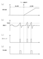
図7(a)~(d)に示すように、判定部13は、車両制御盤4から力行開始信号が入力したときには車両が走行状態であるとして閾値を第2閾値とする。例えば、第2閾値を「2」とする。判定部13は、車両が走行状態であるときには出力信号が2個存在すると、戸挟みありと判定する。車両が走行状態であるときの閾値は、車両が走行状態では走行振動によって出力信号が出力される可能性があるため、車両が停止状態であるときの閾値よりも大きい数が設定される。
As shown in FIGS. 7A to 7D, the
一方、判定部13は、力行開始信号が入力していないときには車両が停止状態であるとして閾値を第1閾値とする。例えば、第1閾値を「1」とする。判定部13は、車両が停止状態であるときには出力信号が1個存在すると、戸挟みありと判定する。
On the other hand, the
図8に示すように、戸挟み検知装置1は、ドア閉指令があるとき(ステップS11:YES)には、出力信号を取得する(ステップS31)。すなわち、取得部11は、第1検知センサ73及び第2検知センサ74から出力信号を取得する。そして、検知信号生成部12は、取得部11が所定期間内に取得した出力信号に含まれる所定基準(判定値)を超えた出力信号の数を計数して、当該数を検知信号として判定部13に出力する。
As shown in FIG. 8, the door
続いて、戸挟み検知装置1は、力行開始信号があるか否かを判定する(ステップS32)。すなわち、判定部13は、力行開始信号の有無によって走行状態であるか否かを判定する。そして、判定部13は、力行開始信号があると判定した場合には(ステップS32:YES)、閾値を第2閾値に設定する(ステップS38)。
Subsequently, the door
一方、判定部13は、力行開始信号がないと判定した場合には(ステップS32:NO)、閾値を第1閾値に設定する(ステップS33)。
続いて、戸挟み検知装置1は、出力信号に含まれる所定基準(判定値)を超えた出力信号の数が閾値に達したか否かを判定する(ステップS34)。すなわち、判定部13は、出力信号に含まれる所定基準(判定値)を超えた出力信号の数が閾値に達していないと判定した場合には(ステップS34:NO)、終了条件が成立するか否かを判定する(ステップS17)。判定部13は、終了条件が成立しない場合には(ステップS17:NO)、ステップS31に移行して処理を継続する。また、判定部13は、終了条件が成立する場合には(ステップS17:YES)、ステップS37に移行する。
On the other hand, when the
Subsequently, the door
一方、判定部13は、出力信号に含まれる所定基準(判定値)を超えた出力信号の数が閾値に達していると判定した場合には(ステップS34:YES)、戸挟みありと判定する(ステップS35)。すなわち、判定部13は、車両の走行振動によって出力信号が出力されていたとしても、停止状態と走行状態とで異なる閾値を設定して判定することで、車両の走行による振動の影響を低減させて判定することができる。図9(a)~(d)に示すように、車両の停止状態で出力信号に含まれる所定基準(判定値)を超えた出力信号が1個存在すると、第1閾値の「1」に達するので、判定部13は戸挟みありと判定する。また、車両の走行状態で、停止状態で戸挟ありと判定されなかった後に、出力信号に含まれる所定基準(判定値)を超えた出力信号が2個存在すると、第2閾値の「2」に達するので、判定部13は戸挟みありと判定する。
On the other hand, when the
ここで、ステップS31~S34及びステップS17の処理を言い換えると、判定部13は、出力信号を継続して取得して、出力信号に含まれる所定基準(判定値)を超えた出力信号の数が閾値に達するか又は終了条件が成立するまで判定を継続する。
Here, in other words, the processing of steps S31 to S34 and step S17, the
続いて、戸挟み検知装置1は、検知信号の取得を停止して(ステップS37)、戸挟み検知処理を終了する。すなわち、取得部11は、出力信号の入力自体を停止してもよい。また、取得部11は、第1検知センサ73及び第2検知センサ74からの出力信号の出力を停止させてもよいし、第1検知センサ73及び第2検知センサ74による圧力の検知を停止させてもよい。
Subsequently, the door
以上説明したように、本実施形態によれば、第1の実施形態の(1)の効果に加え、以下の効果を奏することができる。
(5)取得部11が所定期間内に取得した出力信号に含まれる所定基準(判定値)を超えた出力信号の数を計数して、前記数が閾値以上であるときに戸挟み状態であると判定することで、車両の走行による振動の検知を抑制することができる。
As described above, according to the present embodiment, the following effects can be obtained in addition to the effect of (1) of the first embodiment.
(5) The
(6)車両の力行開始信号が入力したときに車両に駆動力が付与されて車両が走りだすため、車両が走行状態であると判定して戸挟みを検知することができる。
(第4の実施形態)
以下、図9及び図10を参照して、戸挟み検知装置の第4の実施形態について説明する。この実施形態の戸挟み検知装置は、車両の走行状態と停止状態との判定が上記第3の実施形態と異なっている。以下、第3の実施形態との相違点を中心に説明する。
(6) When the power running start signal of the vehicle is input, the driving force is applied to the vehicle and the vehicle starts running. Therefore, it is possible to determine that the vehicle is in a running state and detect the door pinch.
(Fourth Embodiment)
Hereinafter, a fourth embodiment of the door pinch detection device will be described with reference to FIGS. 9 and 10. In the door pinch detection device of this embodiment, the determination of the running state and the stopped state of the vehicle is different from that of the third embodiment. Hereinafter, the differences from the third embodiment will be mainly described.
戸挟み検知装置1は、ブレーキが解除されると、車両制御盤4からドア制御装置2を介してブレーキ解除信号が入力される。判定部13は、このブレーキ解除信号の有無によって車両の走行状態と停止状態とを判定する。
When the brake is released, the door
図9(a)~(d)に示すように、判定部13は、車両制御盤4からブレーキ解除信号が入力したときには車両が走行状態であるとして閾値を第2閾値とする。例えば、第2閾値を「2」とする。判定部13は、車両が走行状態であるときには出力信号に含まれる所定基準を超えた出力信号が2個存在すると、戸挟みありと判定する。車両が走行状態であるときの閾値は、車両が走行状態では走行振動によって出力信号が出力される可能性があるため、車両が停止状態であるときの閾値よりも大きい数が設定される。
As shown in FIGS. 9A to 9D, the
一方、判定部13は、ブレーキ解除信号が入力していないときには車両が停止状態であるとして閾値を第1閾値とする。例えば、第1閾値を「1」とする。判定部13は、車両が停止状態であるときには出力信号に含まれる所定基準(判定値)を超えた出力信号が1個存在すると、戸挟みありと判定する。
On the other hand, the
図10に示すように、戸挟み検知装置1は、ドア閉指令があるとき(ステップS11:YES)には、出力信号を取得する(ステップS31)。すなわち、取得部11は、第1検知センサ73及び第2検知センサ74から出力信号を取得する。そして、検知信号生成部12は、取得部11が所定期間内に取得した出力信号に含まれる所定基準(判定値)を超えた出力信号の数を計数して、当該数を検知信号として判定部13に出力する。
As shown in FIG. 10, the door
続いて、戸挟み検知装置1は、車両が停止状態であるか否かを判定する(ステップS42)。すなわち、判定部13は、ブレーキ解除信号の有無によって停止状態であるか否かを判定する。そして、判定部13は、ブレーキ解除信号がない、すなわち車両が停止状態であると判定した場合には(ステップS42:YES)、閾値を第1閾値に設定する(ステップS33)。
Subsequently, the door
一方、判定部13は、ブレーキ解除信号がある、すなわち車両が走行状態であると判定した場合には(ステップS42:NO)、閾値を第2閾値に設定する(ステップS38)。
以下、第3の実施形態と同様にステップS34~S37、S17の処理を進め、戸挟み検知処理を終了する。
On the other hand, when the
Hereinafter, the processes of steps S34 to S37 and S17 are carried out in the same manner as in the third embodiment, and the door pinch detection process is completed.
以上説明したように、本実施形態によれば、第1の実施形態の(1)の効果及び第3の実施形態の(5)の効果に加え、以下の効果を奏することができる。
(7)車両のブレーキ解除信号が入力したときに車両の制動が解除されて、地形によっては車両が走行することが考えられるので、車両が走行状態であると判定して戸挟みを検知することができる。
As described above, according to the present embodiment, the following effects can be obtained in addition to the effect of (1) of the first embodiment and the effect of (5) of the third embodiment.
(7) When the brake release signal of the vehicle is input, the braking of the vehicle is released, and it is possible that the vehicle runs depending on the terrain. Therefore, it is determined that the vehicle is in a running state and the door pinch is detected. Can be done.
なお、上記実施形態は、これを適宜変更した以下の形態にて実施することもできる。
・上記各実施形態では、第1検知センサ53,73及び第2検知センサ54,74をドアの上部に取り付けたが、第1検知センサ53,73及び第2検知センサ54,74の取付位置は任意に設定可能である。
In addition, the above-mentioned embodiment can also be carried out in the following embodiment which changed this as appropriate.
-In each of the above embodiments, the
・上記第1及び第2の実施形態では、第1検知センサ53及び第2検知センサ54の両方の出力信号を用いて戸挟みを判定したが、いずれか一方のみの出力信号を用いて戸挟みを判定してもよい。
-In the first and second embodiments, the door pinch is determined using the output signals of both the
・上記第3及び第4の実施形態では、第1検知センサ73及び第2検知センサ74の両方の検知信号を用いて戸挟みを判定したが、いずれか一方のみの検知信号を用いて戸挟みを判定してもよい。
-In the third and fourth embodiments, the door pinch is determined by using the detection signals of both the
・上記第2の実施形態では、車両の走行状態に応じて異なる周波数成分を除去するフィルタ12Aを備えるとともに、車両の走行状態に応じて異なる判定値を用いるようにした。しかしながら、車両の走行状態に応じて異なる周波数成分を除去するフィルタ12Aを備えることと、車両の走行状態に応じて異なる判定値を用いることとのいずれか一方のみでもよい。
-In the second embodiment, the
・上記第1及び第2の実施形態では、検知信号生成部12のフィルタ12Aが車両の振動の周波数成分を含む周波数以上の信号を除去した。しかしながら、検知信号生成部12のフィルタ12Aが車両の振動の周波数成分のみの周波数の信号を除去してもよい。
-In the first and second embodiments, the
・上記第3及び第4の実施形態では、車両の走行状態における判定の閾値を第2閾値としたが、車両の速度に応じて閾値を変更してもよい。すなわち、速度の増加に従って第2閾値の次に第3閾値、第4閾値を設定する。なお、閾値の大きさは、第1閾値<第2閾値<第3閾値<第4閾値が好ましい。このようにすれば、車両の速度に応じて閾値が変更されるため、戸挟みの検知精度を更に高めることができる。ここで、「車両の速度に応じて閾値を変更する」には、車両の走行状態と停止状態とで閾値を変更することも含む。 -In the third and fourth embodiments, the threshold value for determination in the running state of the vehicle is set as the second threshold value, but the threshold value may be changed according to the speed of the vehicle. That is, the third threshold value and the fourth threshold value are set next to the second threshold value as the speed increases. The magnitude of the threshold value is preferably the first threshold value <second threshold value <third threshold value <fourth threshold value. By doing so, since the threshold value is changed according to the speed of the vehicle, the detection accuracy of the door pinch can be further improved. Here, "changing the threshold value according to the speed of the vehicle" includes changing the threshold value depending on the running state and the stopped state of the vehicle.
・上記第3及び第4の実施形態では、戸挟み検知装置1は、検知信号生成部12と判定部13とを備えた。しかしながら、判定部13が検知信号生成部12の機能を有してもよい。すなわち、判定部13は、取得部11が所定期間内に取得した出力信号に含まれる所定基準(判定値)を超えた出力信号の数を計数して、当該数が閾値以上であるときに戸挟み状態であると判定してもよい。
-In the third and fourth embodiments, the door
・上記第1及び第2の実施形態では、検知センサとして圧力センサを採用し、上記第3及び第4の実施形態では、検知センサとして圧力スイッチを採用したが、弾性部材51,52の変形量を直接的に計測するひずみセンサ等を採用してもよい。すなわち、「弾性部材の変形を検知する」とは、弾性部材の内部に設けられた中空部内の圧力の変化を検知することにより弾性部材の変形を間接的に検出する形態も、弾性部材の変形を直接的に検出する形態も含まれる。
-In the first and second embodiments, a pressure sensor is adopted as a detection sensor, and in the third and fourth embodiments, a pressure switch is adopted as a detection sensor, but the amount of deformation of the
・上記各実施形態において、図11に示すように、ドア制御装置2が戸挟み検知装置1の機能を備えてもよい。すなわち、ドア制御装置2は、ドア開閉部21及びドア減圧部22に加えて、取得部11と検知信号生成部12と判定部13とを備える。
-In each of the above embodiments, as shown in FIG. 11, the
1…戸挟み検知装置、2…ドア制御装置、3…ドア開閉装置、4…車両制御盤、11…取得部、12…検知信号生成部、12A…フィルタ、13…判定部、21…ドア開閉部、22…ドア減圧部、23…戸閉スイッチ、30…ドア、31…第1ドア、32…第2ドア、41…開閉指令部、42…検知許可部、43…戸挟み報知部、51…第1弾性部材、51A…空間、52…第2弾性部材、52A…空間、53…第1検知センサ、53A…チューブ、54…第2検知センサ、54A…チューブ、60…接触部、73…第1検知センサ、73A…チューブ、74…第2検知センサ、74A…チューブ。 1 ... Door pinch detection device, 2 ... Door control device, 3 ... Door opening / closing device, 4 ... Vehicle control panel, 11 ... Acquisition unit, 12 ... Detection signal generation unit, 12A ... Filter, 13 ... Judgment unit, 21 ... Door opening / closing Unit, 22 ... Door decompression unit, 23 ... Door close switch, 30 ... Door, 31 ... First door, 32 ... Second door, 41 ... Open / close command unit, 42 ... Detection permission unit, 43 ... Door pinch notification unit, 51 ... first elastic member, 51A ... space, 52 ... second elastic member, 52A ... space, 53 ... first detection sensor, 53A ... tube, 54 ... second detection sensor, 54A ... tube, 60 ... contact part, 73 ... First detection sensor, 73A ... tube, 74 ... second detection sensor, 74A ... tube.
Claims (10)
前記ドアの戸先に取り付けられた弾性部材の変形を検知する検知センサからの出力信号を取得する取得部と、
前記取得部が取得した前記出力信号に含まれる前記車両の走行による振動の影響を低減する処理を行って検知信号を生成する検知信号生成部と、
前記検知信号生成部により得られた検知信号に基づいて前記ドアが戸挟み状態であるか否かを判定する判定部と、を備え、
前記検知信号生成部は、前記取得部が取得した前記出力信号から前記車両の走行に起因する振動の周波数成分を低減させた検知信号を生成し、
前記車両の状態が第1状態であると判断される場合には、第1周波数で振動の影響を低減し、
前記車両の状態が前記第1状態の速度よりも速い第2状態であると判断される場合には、前記第1周波数よりも大きい第2周波数で振動の影響を低減する
戸挟み検知装置。 It is a door pinch detection device that detects whether the door that opens and closes the entrance of the vehicle is in the door pinch state.
An acquisition unit that acquires an output signal from a detection sensor that detects deformation of the elastic member attached to the door end of the door, and an acquisition unit.
A detection signal generation unit that generates a detection signal by performing a process of reducing the influence of vibration due to the running of the vehicle included in the output signal acquired by the acquisition unit.
A determination unit for determining whether or not the door is pinched based on the detection signal obtained by the detection signal generation unit is provided .
The detection signal generation unit generates a detection signal in which the frequency component of vibration caused by the running of the vehicle is reduced from the output signal acquired by the acquisition unit.
When it is determined that the state of the vehicle is the first state, the influence of vibration is reduced at the first frequency.
When it is determined that the state of the vehicle is a second state faster than the speed of the first state, the influence of vibration is reduced at a second frequency higher than the first frequency.
Door pinch detection device.
請求項1に記載の戸挟み検知装置。 The door pinch detection device according to claim 1 , wherein the determination unit makes a determination by comparing the detection signal with the determination value, and makes a determination using the determination value that differs depending on the state of the vehicle.
前記ドアの戸先に取り付けられた弾性部材の変形を検知する検知センサからの出力信号を取得する取得部と、
前記取得部が取得した前記出力信号に含まれる前記車両の走行による振動の影響を低減する処理を行って検知信号を生成する検知信号生成部と、
前記検知信号生成部により得られた検知信号に基づいて前記ドアが戸挟み状態であるか否かを判定する判定部と、を備え、
前記検知信号生成部は、前記取得部が取得した前記出力信号から前記車両の走行に起因する振動の周波数成分を低減させた検知信号を生成し、
前記判定部は、前記検知信号と判定値との比較により判定し、前記車両の状態に応じて異なる前記判定値を用いて判定し、
前記車両の状態が第1状態であると判断される場合には、第1判定値を用いて判定し、
前記車両の状態が前記第1状態の速度よりも速い第2状態であると判断される場合には、前記第1判定値よりも大きい第2判定値を用いて判定する
戸挟み検知装置。 It is a door pinch detection device that detects whether the door that opens and closes the entrance of the vehicle is in the door pinch state.
An acquisition unit that acquires an output signal from a detection sensor that detects deformation of the elastic member attached to the door end of the door, and an acquisition unit.
A detection signal generation unit that generates a detection signal by performing a process of reducing the influence of vibration due to the running of the vehicle included in the output signal acquired by the acquisition unit.
A determination unit for determining whether or not the door is pinched based on the detection signal obtained by the detection signal generation unit is provided .
The detection signal generation unit generates a detection signal in which the frequency component of vibration caused by the running of the vehicle is reduced from the output signal acquired by the acquisition unit.
The determination unit makes a determination by comparing the detection signal with the determination value, and makes a determination using the determination value different depending on the state of the vehicle.
When it is determined that the state of the vehicle is the first state, it is determined using the first determination value.
When it is determined that the state of the vehicle is the second state faster than the speed of the first state, the determination is made using the second determination value larger than the first determination value.
Door pinch detection device.
前記判定部は、前記数が閾値以上であるときに戸挟み状態であると判定する
請求項1~3のいずれか一項に記載の戸挟み検知装置。 The detection signal generation unit counts the number of output signals in the output signal acquired by the acquisition unit within a predetermined period and exceeds a predetermined reference, and generates the number as a detection signal.
The door pinch detection device according to any one of claims 1 to 3 , wherein the determination unit determines that the door pinch state is obtained when the number is equal to or greater than a threshold value.
請求項4に記載の戸挟み検知装置。 The door pinch detection device according to claim 4 , wherein the determination unit changes the threshold value according to the speed of the vehicle.
請求項4又は5に記載の戸挟み検知装置。 The door pinch detection device according to claim 4 or 5 , wherein the determination unit changes the threshold value when a drive start signal of the vehicle is input.
請求項4又は5に記載の戸挟み検知装置。 The door pinch detection device according to claim 4 or 5 , wherein the determination unit changes the threshold value when a brake release signal of the vehicle is input.
前記検知センサは、前記弾性部材の内部に形成されている中空部内の圧力を検知する圧力センサである
請求項1~7のいずれか一項に記載の戸挟み検知装置。 Equipped with the detection sensor
The door pinch detection device according to any one of claims 1 to 7 , wherein the detection sensor is a pressure sensor that detects the pressure in the hollow portion formed inside the elastic member.
前記ドアの開閉を制御するドア制御装置を備え、
前記ドア制御装置は、
前記ドアの戸先に取り付けられた弾性部材の変形を検知する検知センサからの出力信号を取得する取得部と、
前記取得部が取得した前記出力信号に含まれる前記車両の走行による振動の影響を低減する処理を行って検知信号を生成する検知信号生成部と、
前記検知信号生成部により得られた検知信号に基づいて前記ドアが戸挟み状態であるか否かを判定する判定部と、を備え、
前記検知信号生成部は、前記取得部が取得した前記出力信号から前記車両の走行に起因する振動の周波数成分を低減させた検知信号を生成し、
前記車両の状態が第1状態であると判断される場合には、第1周波数で振動の影響を低減し、
前記車両の状態が前記第1状態の速度よりも速い第2状態であると判断される場合には、前記第1周波数よりも大きい第2周波数で振動の影響を低減する
ドア開閉装置。 A door opening / closing device that opens and closes vehicle doors.
A door control device for controlling the opening and closing of the door is provided.
The door control device is
An acquisition unit that acquires an output signal from a detection sensor that detects deformation of the elastic member attached to the door end of the door, and an acquisition unit.
A detection signal generation unit that generates a detection signal by performing a process of reducing the influence of vibration due to the running of the vehicle included in the output signal acquired by the acquisition unit.
A determination unit for determining whether or not the door is pinched based on the detection signal obtained by the detection signal generation unit is provided .
The detection signal generation unit generates a detection signal in which the frequency component of vibration caused by the running of the vehicle is reduced from the output signal acquired by the acquisition unit.
When it is determined that the state of the vehicle is the first state, the influence of vibration is reduced at the first frequency.
When it is determined that the state of the vehicle is a second state faster than the speed of the first state, the influence of vibration is reduced at a second frequency higher than the first frequency.
Door switchgear.
前記ドアの開閉を制御するドア制御装置を備え、
前記ドア制御装置は、
前記ドアの戸先に取り付けられた弾性部材の変形を検知する検知センサからの出力信号を取得する取得部と、
前記取得部が取得した前記出力信号に含まれる前記車両の走行による振動の影響を低減する処理を行って検知信号を生成する検知信号生成部と、
前記検知信号生成部により得られた検知信号に基づいて前記ドアが戸挟み状態であるか否かを判定する判定部と、を備え、
前記検知信号生成部は、前記取得部が取得した前記出力信号から前記車両の走行に起因する振動の周波数成分を低減させた検知信号を生成し、
前記判定部は、前記検知信号と判定値との比較により判定し、前記車両の状態に応じて異なる前記判定値を用いて判定し、
前記車両の状態が第1状態であると判断される場合には、第1判定値を用いて判定し、
前記車両の状態が前記第1状態の速度よりも速い第2状態であると判断される場合には、前記第1判定値よりも大きい第2判定値を用いて判定する
ドア開閉装置。 A door opening / closing device that opens and closes vehicle doors.
A door control device for controlling the opening and closing of the door is provided.
The door control device is
An acquisition unit that acquires an output signal from a detection sensor that detects deformation of the elastic member attached to the door end of the door, and an acquisition unit.
A detection signal generation unit that generates a detection signal by performing a process of reducing the influence of vibration due to the running of the vehicle included in the output signal acquired by the acquisition unit.
A determination unit for determining whether or not the door is pinched based on the detection signal obtained by the detection signal generation unit is provided .
The detection signal generation unit generates a detection signal in which the frequency component of vibration caused by the running of the vehicle is reduced from the output signal acquired by the acquisition unit.
The determination unit makes a determination by comparing the detection signal with the determination value, and makes a determination using the determination value different depending on the state of the vehicle.
When it is determined that the state of the vehicle is the first state, it is determined using the first determination value.
When it is determined that the state of the vehicle is the second state faster than the speed of the first state, the determination is made using the second determination value larger than the first determination value.
Door switchgear.
Priority Applications (4)
| Application Number | Priority Date | Filing Date | Title |
|---|---|---|---|
| JP2017224882A JP6990567B2 (en) | 2017-11-22 | 2017-11-22 | Door pinch detection device and door opening / closing device |
| EP18207192.8A EP3489447B1 (en) | 2017-11-22 | 2018-11-20 | Door entrapment detector and door opening-closing device |
| CN201811386388.8A CN109812166B (en) | 2017-11-22 | 2018-11-20 | Door clamp detecting device and door opening and closing device |
| TW107141280A TWI695792B (en) | 2017-11-22 | 2018-11-20 | Door entrapment detector and door opening-closing device |
Applications Claiming Priority (1)
| Application Number | Priority Date | Filing Date | Title |
|---|---|---|---|
| JP2017224882A JP6990567B2 (en) | 2017-11-22 | 2017-11-22 | Door pinch detection device and door opening / closing device |
Publications (3)
| Publication Number | Publication Date |
|---|---|
| JP2019093900A JP2019093900A (en) | 2019-06-20 |
| JP2019093900A5 JP2019093900A5 (en) | 2020-12-10 |
| JP6990567B2 true JP6990567B2 (en) | 2022-01-12 |
Family
ID=64402045
Family Applications (1)
| Application Number | Title | Priority Date | Filing Date |
|---|---|---|---|
| JP2017224882A Active JP6990567B2 (en) | 2017-11-22 | 2017-11-22 | Door pinch detection device and door opening / closing device |
Country Status (4)
| Country | Link |
|---|---|
| EP (1) | EP3489447B1 (en) |
| JP (1) | JP6990567B2 (en) |
| CN (1) | CN109812166B (en) |
| TW (1) | TWI695792B (en) |
Families Citing this family (2)
| Publication number | Priority date | Publication date | Assignee | Title |
|---|---|---|---|---|
| FR3097637B1 (en) * | 2019-06-18 | 2021-05-28 | Psa Automobiles Sa | Method for managing a motorized assistance mechanism when opening a motor vehicle door |
| CN110566075B (en) * | 2019-09-29 | 2020-11-03 | 白云帆 | Automatic protective shielding door |
Citations (6)
| Publication number | Priority date | Publication date | Assignee | Title |
|---|---|---|---|---|
| US20030192252A1 (en) | 1999-10-05 | 2003-10-16 | Harrison Nicholas Charles | Detection of obstruction of doors |
| JP2004003159A (en) | 2002-05-31 | 2004-01-08 | Aisin Seiki Co Ltd | Apparatus for sensing object caught in opening/closing body |
| WO2004090273A1 (en) | 2003-04-09 | 2004-10-21 | Matsushita Electric Industrial Co., Ltd. | Moving device and open/close control device for moving body |
| JP2006064594A (en) | 2004-08-27 | 2006-03-09 | Aisin Seiki Co Ltd | Pinching detection device |
| WO2007000797A1 (en) | 2005-06-27 | 2007-01-04 | Aisin Seiki Kabushiki Kaisha | Device for controlling opening/closing body for vehicle |
| JP2016159847A (en) | 2015-03-04 | 2016-09-05 | 西日本旅客鉄道株式会社 | Door catching detection device |
Family Cites Families (6)
| Publication number | Priority date | Publication date | Assignee | Title |
|---|---|---|---|---|
| JPH09317322A (en) * | 1996-05-31 | 1997-12-09 | Sensor Technol Kk | Automatic opening/closing door of vehicles and preventive device against being caught by window |
| CN1288321C (en) * | 1999-05-13 | 2006-12-06 | 松下电器产业株式会社 | Pressure-sensitive sensor and object detecting device |
| JP3182411B2 (en) * | 1999-08-11 | 2001-07-03 | 川崎重工業株式会社 | Door pinch detection device |
| JP2004308304A (en) * | 2003-04-09 | 2004-11-04 | Matsushita Electric Ind Co Ltd | Moving body opening/closing control device |
| JP4914131B2 (en) * | 2006-06-30 | 2012-04-11 | パナソニック電工Sunx株式会社 | Door clamp detector |
| JP2012076566A (en) * | 2010-09-30 | 2012-04-19 | Panasonic Electric Works Sunx Co Ltd | Door catching detection device |
-
2017
- 2017-11-22 JP JP2017224882A patent/JP6990567B2/en active Active
-
2018
- 2018-11-20 CN CN201811386388.8A patent/CN109812166B/en active Active
- 2018-11-20 EP EP18207192.8A patent/EP3489447B1/en active Active
- 2018-11-20 TW TW107141280A patent/TWI695792B/en active
Patent Citations (6)
| Publication number | Priority date | Publication date | Assignee | Title |
|---|---|---|---|---|
| US20030192252A1 (en) | 1999-10-05 | 2003-10-16 | Harrison Nicholas Charles | Detection of obstruction of doors |
| JP2004003159A (en) | 2002-05-31 | 2004-01-08 | Aisin Seiki Co Ltd | Apparatus for sensing object caught in opening/closing body |
| WO2004090273A1 (en) | 2003-04-09 | 2004-10-21 | Matsushita Electric Industrial Co., Ltd. | Moving device and open/close control device for moving body |
| JP2006064594A (en) | 2004-08-27 | 2006-03-09 | Aisin Seiki Co Ltd | Pinching detection device |
| WO2007000797A1 (en) | 2005-06-27 | 2007-01-04 | Aisin Seiki Kabushiki Kaisha | Device for controlling opening/closing body for vehicle |
| JP2016159847A (en) | 2015-03-04 | 2016-09-05 | 西日本旅客鉄道株式会社 | Door catching detection device |
Also Published As
| Publication number | Publication date |
|---|---|
| TWI695792B (en) | 2020-06-11 |
| TW201927612A (en) | 2019-07-16 |
| JP2019093900A (en) | 2019-06-20 |
| CN109812166A (en) | 2019-05-28 |
| EP3489447A1 (en) | 2019-05-29 |
| CN109812166B (en) | 2021-10-22 |
| EP3489447B1 (en) | 2023-05-31 |
Similar Documents
| Publication | Publication Date | Title |
|---|---|---|
| JP6990567B2 (en) | Door pinch detection device and door opening / closing device | |
| WO2013129261A1 (en) | Device for controlling vehicle opening/closing element | |
| JP6141987B2 (en) | Vehicle opening / closing body control apparatus and vehicle opening / closing system | |
| US10464399B2 (en) | Vehicle window opening device | |
| CN106812410B (en) | Switch member control apparatus for vehicle | |
| KR101106475B1 (en) | Pinch protection method and device for a motor-driven closing system | |
| EP3272014B1 (en) | Reducing erroneous detection of input command gestures | |
| JP2007315069A (en) | Vehicular automatic opening-closing device | |
| US6924614B2 (en) | Opening and closing control device for opening and closing member of vehicle | |
| US20190330910A1 (en) | Method for controlling a drive arrangement for a flap of a motor vehicle | |
| JP7002301B2 (en) | Door pinch detection device and door opening / closing device | |
| US10626658B2 (en) | Control device for a vehicle having an automatically closing hatch | |
| JP2010053528A (en) | Apparatus for controlling electrically-driven door | |
| KR20050057437A (en) | Method for the detection of an impact | |
| JP2019093900A5 (en) | ||
| JP3070465B2 (en) | Tire pressure detector | |
| US20200224476A1 (en) | Vehicle door device | |
| JP7181788B2 (en) | Traction detection device for railway vehicles | |
| JP7387861B2 (en) | Railway vehicle side sliding door control device | |
| JP6288919B2 (en) | Vehicle door control device | |
| JP2012036567A (en) | Door opening/closing drive unit | |
| JP2019019493A (en) | Power window device | |
| JP2002200979A (en) | Jinrikisha | |
| JP2007169002A (en) | Elevator abnormality detecting device | |
| JP2628261B2 (en) | Door closing device for vehicle door |
Legal Events
| Date | Code | Title | Description |
|---|---|---|---|
| A521 | Request for written amendment filed |
Free format text: JAPANESE INTERMEDIATE CODE: A523 Effective date: 20201016 |
|
| A621 | Written request for application examination |
Free format text: JAPANESE INTERMEDIATE CODE: A621 Effective date: 20201016 |
|
| A977 | Report on retrieval |
Free format text: JAPANESE INTERMEDIATE CODE: A971007 Effective date: 20210831 |
|
| A131 | Notification of reasons for refusal |
Free format text: JAPANESE INTERMEDIATE CODE: A131 Effective date: 20210901 |
|
| A521 | Request for written amendment filed |
Free format text: JAPANESE INTERMEDIATE CODE: A523 Effective date: 20211029 |
|
| TRDD | Decision of grant or rejection written | ||
| A01 | Written decision to grant a patent or to grant a registration (utility model) |
Free format text: JAPANESE INTERMEDIATE CODE: A01 Effective date: 20211116 |
|
| A61 | First payment of annual fees (during grant procedure) |
Free format text: JAPANESE INTERMEDIATE CODE: A61 Effective date: 20211206 |
|
| R151 | Written notification of patent or utility model registration |
Ref document number: 6990567 Country of ref document: JP Free format text: JAPANESE INTERMEDIATE CODE: R151 |