JP6989508B2 - Disinfection cap for IV needleless connectors - Google Patents
Disinfection cap for IV needleless connectors Download PDFInfo
- Publication number
- JP6989508B2 JP6989508B2 JP2018537466A JP2018537466A JP6989508B2 JP 6989508 B2 JP6989508 B2 JP 6989508B2 JP 2018537466 A JP2018537466 A JP 2018537466A JP 2018537466 A JP2018537466 A JP 2018537466A JP 6989508 B2 JP6989508 B2 JP 6989508B2
- Authority
- JP
- Japan
- Prior art keywords
- thread
- cap
- contour
- starting
- path
- Prior art date
- Legal status (The legal status is an assumption and is not a legal conclusion. Google has not performed a legal analysis and makes no representation as to the accuracy of the status listed.)
- Active
Links
Images


Classifications
-
- A—HUMAN NECESSITIES
- A61—MEDICAL OR VETERINARY SCIENCE; HYGIENE
- A61M—DEVICES FOR INTRODUCING MEDIA INTO, OR ONTO, THE BODY; DEVICES FOR TRANSDUCING BODY MEDIA OR FOR TAKING MEDIA FROM THE BODY; DEVICES FOR PRODUCING OR ENDING SLEEP OR STUPOR
- A61M39/00—Tubes, tube connectors, tube couplings, valves, access sites or the like, specially adapted for medical use
- A61M39/20—Closure caps or plugs for connectors or open ends of tubes
-
- A—HUMAN NECESSITIES
- A61—MEDICAL OR VETERINARY SCIENCE; HYGIENE
- A61B—DIAGNOSIS; SURGERY; IDENTIFICATION
- A61B90/00—Instruments, implements or accessories specially adapted for surgery or diagnosis and not covered by any of the groups A61B1/00 - A61B50/00, e.g. for luxation treatment or for protecting wound edges
- A61B90/70—Cleaning devices specially adapted for surgical instruments
-
- A—HUMAN NECESSITIES
- A61—MEDICAL OR VETERINARY SCIENCE; HYGIENE
- A61M—DEVICES FOR INTRODUCING MEDIA INTO, OR ONTO, THE BODY; DEVICES FOR TRANSDUCING BODY MEDIA OR FOR TAKING MEDIA FROM THE BODY; DEVICES FOR PRODUCING OR ENDING SLEEP OR STUPOR
- A61M39/00—Tubes, tube connectors, tube couplings, valves, access sites or the like, specially adapted for medical use
- A61M39/10—Tube connectors; Tube couplings
- A61M39/16—Tube connectors; Tube couplings having provision for disinfection or sterilisation
- A61M39/162—Tube connectors; Tube couplings having provision for disinfection or sterilisation with antiseptic agent incorporated within the connector
-
- A—HUMAN NECESSITIES
- A61—MEDICAL OR VETERINARY SCIENCE; HYGIENE
- A61M—DEVICES FOR INTRODUCING MEDIA INTO, OR ONTO, THE BODY; DEVICES FOR TRANSDUCING BODY MEDIA OR FOR TAKING MEDIA FROM THE BODY; DEVICES FOR PRODUCING OR ENDING SLEEP OR STUPOR
- A61M39/00—Tubes, tube connectors, tube couplings, valves, access sites or the like, specially adapted for medical use
- A61M39/10—Tube connectors; Tube couplings
- A61M39/16—Tube connectors; Tube couplings having provision for disinfection or sterilisation
- A61M39/165—Shrouds or protectors for aseptically enclosing the connector
-
- A—HUMAN NECESSITIES
- A61—MEDICAL OR VETERINARY SCIENCE; HYGIENE
- A61M—DEVICES FOR INTRODUCING MEDIA INTO, OR ONTO, THE BODY; DEVICES FOR TRANSDUCING BODY MEDIA OR FOR TAKING MEDIA FROM THE BODY; DEVICES FOR PRODUCING OR ENDING SLEEP OR STUPOR
- A61M39/00—Tubes, tube connectors, tube couplings, valves, access sites or the like, specially adapted for medical use
- A61M39/10—Tube connectors; Tube couplings
- A61M39/16—Tube connectors; Tube couplings having provision for disinfection or sterilisation
- A61M39/18—Methods or apparatus for making the connection under sterile conditions, i.e. sterile docking
-
- A—HUMAN NECESSITIES
- A61—MEDICAL OR VETERINARY SCIENCE; HYGIENE
- A61M—DEVICES FOR INTRODUCING MEDIA INTO, OR ONTO, THE BODY; DEVICES FOR TRANSDUCING BODY MEDIA OR FOR TAKING MEDIA FROM THE BODY; DEVICES FOR PRODUCING OR ENDING SLEEP OR STUPOR
- A61M39/00—Tubes, tube connectors, tube couplings, valves, access sites or the like, specially adapted for medical use
- A61M39/02—Access sites
- A61M2039/0205—Access sites for injecting media
-
- A—HUMAN NECESSITIES
- A61—MEDICAL OR VETERINARY SCIENCE; HYGIENE
- A61M—DEVICES FOR INTRODUCING MEDIA INTO, OR ONTO, THE BODY; DEVICES FOR TRANSDUCING BODY MEDIA OR FOR TAKING MEDIA FROM THE BODY; DEVICES FOR PRODUCING OR ENDING SLEEP OR STUPOR
- A61M39/00—Tubes, tube connectors, tube couplings, valves, access sites or the like, specially adapted for medical use
- A61M39/02—Access sites
- A61M39/0247—Semi-permanent or permanent transcutaneous or percutaneous access sites to the inside of the body
- A61M2039/0258—Semi-permanent or permanent transcutaneous or percutaneous access sites to the inside of the body for vascular access, e.g. blood stream access
-
- A—HUMAN NECESSITIES
- A61—MEDICAL OR VETERINARY SCIENCE; HYGIENE
- A61M—DEVICES FOR INTRODUCING MEDIA INTO, OR ONTO, THE BODY; DEVICES FOR TRANSDUCING BODY MEDIA OR FOR TAKING MEDIA FROM THE BODY; DEVICES FOR PRODUCING OR ENDING SLEEP OR STUPOR
- A61M39/00—Tubes, tube connectors, tube couplings, valves, access sites or the like, specially adapted for medical use
- A61M39/02—Access sites
- A61M39/0247—Semi-permanent or permanent transcutaneous or percutaneous access sites to the inside of the body
- A61M2039/0285—Semi-permanent or permanent transcutaneous or percutaneous access sites to the inside of the body with sterilisation means, e.g. antibacterial coatings, disinfecting pads, UV radiation LEDs or heating means in the port
-
- A—HUMAN NECESSITIES
- A61—MEDICAL OR VETERINARY SCIENCE; HYGIENE
- A61M—DEVICES FOR INTRODUCING MEDIA INTO, OR ONTO, THE BODY; DEVICES FOR TRANSDUCING BODY MEDIA OR FOR TAKING MEDIA FROM THE BODY; DEVICES FOR PRODUCING OR ENDING SLEEP OR STUPOR
- A61M39/00—Tubes, tube connectors, tube couplings, valves, access sites or the like, specially adapted for medical use
- A61M39/02—Access sites
- A61M39/0247—Semi-permanent or permanent transcutaneous or percutaneous access sites to the inside of the body
- A61M2039/0288—Semi-permanent or permanent transcutaneous or percutaneous access sites to the inside of the body protectors, caps or covers therefor
-
- A—HUMAN NECESSITIES
- A61—MEDICAL OR VETERINARY SCIENCE; HYGIENE
- A61M—DEVICES FOR INTRODUCING MEDIA INTO, OR ONTO, THE BODY; DEVICES FOR TRANSDUCING BODY MEDIA OR FOR TAKING MEDIA FROM THE BODY; DEVICES FOR PRODUCING OR ENDING SLEEP OR STUPOR
- A61M39/00—Tubes, tube connectors, tube couplings, valves, access sites or the like, specially adapted for medical use
- A61M39/10—Tube connectors; Tube couplings
- A61M2039/1033—Swivel nut connectors, e.g. threaded connectors, bayonet-connectors
-
- A—HUMAN NECESSITIES
- A61—MEDICAL OR VETERINARY SCIENCE; HYGIENE
- A61M—DEVICES FOR INTRODUCING MEDIA INTO, OR ONTO, THE BODY; DEVICES FOR TRANSDUCING BODY MEDIA OR FOR TAKING MEDIA FROM THE BODY; DEVICES FOR PRODUCING OR ENDING SLEEP OR STUPOR
- A61M39/00—Tubes, tube connectors, tube couplings, valves, access sites or the like, specially adapted for medical use
- A61M39/10—Tube connectors; Tube couplings
- A61M2039/1038—Union screw connectors, e.g. hollow screw or sleeve having external threads
-
- A—HUMAN NECESSITIES
- A61—MEDICAL OR VETERINARY SCIENCE; HYGIENE
- A61M—DEVICES FOR INTRODUCING MEDIA INTO, OR ONTO, THE BODY; DEVICES FOR TRANSDUCING BODY MEDIA OR FOR TAKING MEDIA FROM THE BODY; DEVICES FOR PRODUCING OR ENDING SLEEP OR STUPOR
- A61M39/00—Tubes, tube connectors, tube couplings, valves, access sites or the like, specially adapted for medical use
- A61M39/20—Closure caps or plugs for connectors or open ends of tubes
- A61M2039/205—Closure caps or plugs for connectors or open ends of tubes comprising air venting means
-
- A—HUMAN NECESSITIES
- A61—MEDICAL OR VETERINARY SCIENCE; HYGIENE
- A61M—DEVICES FOR INTRODUCING MEDIA INTO, OR ONTO, THE BODY; DEVICES FOR TRANSDUCING BODY MEDIA OR FOR TAKING MEDIA FROM THE BODY; DEVICES FOR PRODUCING OR ENDING SLEEP OR STUPOR
- A61M39/00—Tubes, tube connectors, tube couplings, valves, access sites or the like, specially adapted for medical use
- A61M39/02—Access sites
- A61M39/0247—Semi-permanent or permanent transcutaneous or percutaneous access sites to the inside of the body
Description
関連出願の相互参照
本出願は、2016年1月18日に出願された米国仮出願第62/279,986号および2016年2月26日に出願された米国仮出願第62/300,247号からの35USC§119(e)に基づく優先権を主張し、その内容(それと共に提出された全ての添付書類を含む)は、それによってその全体が参照によって組み込まれる。
Cross-references to related applications This application is for US Provisional Application Nos. 62 / 279,986 filed January 18, 2016 and US Provisional Application Nos. 62/300, 247 filed February 26, 2016. Claims priority under 35 USC § 119 (e) from, and its content (including all attachments submitted with it) is thereby incorporated by reference in its entirety.
概して、本発明の例示的な実施形態は、医療用消毒キャップの分野、および特に、IVニードルレスコネクタと共に使用するための消毒キャップに関する。 In general, exemplary embodiments of the invention relate to the field of medical disinfection caps and, in particular, disinfection caps for use with IV needleless connectors.
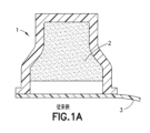
高いコストおよび高い関連死亡率を伴うインパクトの強いイベントであるカテーテル関連血流感染(CRBSI)の件数を減少させるために、消毒キャップが特許文献2として発行される特許文献1に最初に開示され(その両方の開示全体は、参照によって本明細書中に組み込まれる)および市場に紹介されて以来、ニードルレスコネクタ消毒キャップ空間は急速に拡大し続けている。特許文献2に開示されるもののような消毒キャップは、図1Aおよび図1Bに図示されており、そこでキャップ1は、消毒パッド2および蓋3を含み、およびキャップ4は、消毒パッド5および蓋7ならびにニードルレスコネクタハブと噛み合うためのその内周8上のねじ山6をも含む。図2に図示されるように、図1Aおよび図1Bのキャップ1および/またはキャップ4のような複数の消毒キャップ23は、IVポール(IV pole)上にストリップ22を吊るすための開口部24を含むストリップ22上に配置され得る。IVポール吊るしデバイス21において、ストリップ22は、取り外されたキャップ25がニードルレスコネクタ上にすぐに配置できるように、その上に配置されたキャップ23のための、例えば蓋3および/または7と同じ機能を有する、共通の蓋としての役割を果たし得る。
In order to reduce the number of catheter-related bloodstream infections (CRBSI), which is a high-impact event with high cost and high associated mortality, the disinfectant cap is first disclosed in
消毒キャップは、米国医療疫学学会(SHEA)ガイドラインに加えられており、および早期指摘は、キャップは、また、2016輸液看護師基準(INS)ガイドラインにも組み入れられるであろうということである。 Disinfectant caps have been added to the American Society of Medical Epidemiology (SHEA) guidelines, and an early indication is that caps will also be incorporated into the 2016 Infusion Nurse Standards (INS) guidelines.
発展した市場において、IVカテーテルを利用するとき、ニードルレスコネクタは、典型的には、システムを遮断するために使用され、および次いでその後に、薬物または他の必要な流体をカテーテルを介して患者に投与するためにアクセスされる。INS実施基準(INS Standards of Practice)は、ニードルレスコネクタの使用を推奨し、および「各アクセスの前に、アルコール、ヨウ素のチンキ剤またはグルコン酸クロルヘキシジン/アルコールの組み合わせを使用して一貫しておよび完全に消毒される」べきであることを表明している。ニードルレスコネクタの消毒は、表面上に生存しておりおよび前に記載されたCRBSIイベントを含む様々なカテーテル関連合併症をもたらす可能性のあるバクテリアの減少に役立つことが最終的に意図される。看護師は、典型的には70%IPAアルコールパッドを利用して「ハブをこすり洗いすること(scrubbing the hub)」として知られていることを行うことによって、この消毒タスクを完了することとなる。しかしながら、この実務に対するコンプライアンスは、典型的には非常に低い。「ハブをこすり洗いすること」に対するコンプライアンスの欠如に加えて、また、臨床医インタビューを通して、こすり洗い時間、乾燥時間、およびニードルレスコネクタがこすり洗いされる回数にしばしば変動があることも知られている。 In the developed market, when utilizing IV catheters, needleless connectors are typically used to shut off the system, and then a drug or other required fluid to the patient via the catheter. Accessed for administration. The INS Standards of Practice recommend the use of needleless connectors and "consistently and with alcohol, iodine tinctures or chlorhexidine gluconate / alcohol combinations prior to each access. It has stated that it should be "completely disinfected." Disinfection of needleless connectors is ultimately intended to help reduce bacteria that are alive on the surface and can lead to various catheter-related complications, including the CRBSI events previously described. Nurses will complete this disinfection task by doing what is typically known as "scrubbing the hub" with a 70% IPA alcohol pad. .. However, compliance with this practice is typically very low. In addition to the lack of compliance with "rubbing the hub", it is also known through clinician interviews that there are often variations in scrubbing time, drying time, and the number of times needleless connectors are scrubbed. There is.
キャップ技術は、ニードルレスコネクタに関連する重大な課題を提示する。現在市販されている消毒キャップの全ては、活性消毒成分として70%イソプロピルアルコールを含有する。しかしながら、ニードルレスコネクタ設計の多くは、メインハウジングのためにアクリルまたは同様の材料を使用する。アクリルは、長い露出時間にわたって、軽度から劣った化学的安定性のイソプロピルアルコール耐性を有する。したがって、イソプロピルアルコールは、変色および/またはニードルレスコネクタ材料のクラッキングの形で、アクリルの化学的ブレークダウンダメージを引き起こす可能性がある。加えて、市販されているニードルレスコネクタのほとんど全ては、流体経路弁設計のためにシリコーン材料を使用する。シリコーン材料は、長い露出時間にわたって軽度から劣った化学的安定性のイソプロピルアルコール耐性を有する。これは、次いでニードルレスコネクタ弁がくっついて閉じおよび/または閉じることができないことを引き起こす(血液漏出を引き起こす)可能性のある、シリコーン部品の膨張をもたらす可能性がある。その上、増大したシリコーン膨張は、外側アクリルニードルレスコネクタハウジングのクラッキング問題を拡大させ得るコネクタハウジング上の応力を増大させ得る。 Cap technology presents significant challenges associated with needleless connectors. All disinfectant caps currently on the market contain 70% isopropyl alcohol as an active disinfectant component. However, many needleless connector designs use acrylic or similar materials for the main housing. Acrylic has mild to inferior chemical stability isopropyl alcohol resistance over long exposure times. Therefore, isopropyl alcohol can cause chemical breakdown damage to the acrylic in the form of discoloration and / or cracking of the needleless connector material. In addition, almost all needleless connectors on the market use silicone materials for fluid path valve design. Silicone materials have mild to inferior chemical stability isopropyl alcohol resistance over long exposure times. This can result in swelling of the silicone component, which can then cause the needleless connector valve to stick together and not close and / or close (causing blood leakage). Moreover, the increased silicone expansion can increase the stress on the connector housing which can exacerbate the cracking problem of the outer acrylic needleless connector housing.
従来、ニードルレスコネクタ材料とのイソプロピルアルコールの化学的不適合性の問題に取り組むために、(特許文献3、特許文献4、および特許文献5に記載されたもののような)アルコール通気口を有する消毒キャップが開発されてきた。そのような通気口は、キャップが、そのような通気口を有さない現在市販されているキャップよりも速く、消毒用アルコール(disinfecting alcohol)をニードルレスコネクタから離れて通気することを可能にする。従って、アルコール通気は、ニードルレスコネクタ材料に対する化学的ダメージを低減させることができる。
Traditionally, disinfectant caps with alcohol vents (such as those described in
しかしながら、そのような従来の通気口機構は、いくつかの重大な欠点を有する。1つの欠点は、通気機構は、例えば特許文献6に記載されたように、キャップ内に専用の通気穴を形成することを必要とするか、または重要なアンダーカット範囲および/または2つの成型部品、主キャップハウジングおよびねじ山リングの組立品に依存する可能性があることである。そのような従来の通気機構は、キャップ設計を、別々の部品の成型を必要とするように追いやる。これら別々の部品は、合わせて、次いで組み立てられ、次いで溶接されまたは接着結合されなければならない。従って、そのような設計は、例えばシングルショット成型されたキャップハウジング設計と比べて、本来的に高い工具費、製造複雑性、および生産費を有する。
However, such conventional vent mechanisms have some serious drawbacks. One drawback is that the ventilation mechanism requires, for example, to form a dedicated ventilation hole in the cap, as described in
従って、もしアンダーカットを回避する通気機構を含む消毒キャップが開発されたとしたら、それは、費用が掛かる組み立て工程および溶接工程を排除し得る。加えて、もし増大された通気性能を持つ消毒キャップが開発されたとしたら、それは、ニードルレスコネクタの機能不全をさらに低減させる可能性がある。 Therefore, if a disinfectant cap with a ventilation mechanism to avoid undercuts is developed, it can eliminate costly assembly and welding steps. In addition, if a disinfectant cap with increased ventilation performance is developed, it has the potential to further reduce the malfunction of needleless connectors.
本発明の態様に従って、消毒キャップは、閉鎖頂部を含むハウジング、本質的に円筒状の側壁、および前記ニードルレスコネクタの相手機構(mating feature)を含む先端部を受け入れるための前記ハウジング内部の内部空間への開口部を有する前記側壁によって形成された開放底部を含む。消毒スポンジは、キャップの使用前に内部空洞内部にスポンジを封止するための内部空洞への開口部を封止する取り外し可能なカバーにより、内部空洞内部に構成され得る。内部空洞は、側壁の内側側壁表面上に少なくとも1つのねじ山を含む。キャップねじ山は、ニードルレスコネクタの相手機構と噛み合うのに十分であり、キャップねじ山は、ニードルレスコネクタの相手機構に対応しない。 According to aspects of the invention, the disinfectant cap is an internal space inside the housing for receiving a housing including a closed top, an essentially cylindrical side wall, and a tip including a mating feature of the needleless connector. Includes an open bottom formed by the sidewall having an opening to. The disinfectant sponge may be configured inside the internal cavity with a removable cover that seals the opening to the internal cavity for sealing the sponge inside the internal cavity prior to use of the cap. The internal cavity comprises at least one thread on the inner sidewall surface of the sidewall. The cap thread is sufficient to mesh with the mating mechanism of the needleless connector, and the cap thread does not correspond to the mating mechanism of the needleless connector.
本発明の別の態様に従って、キャップねじ山の大径、小径、ピッチ、ねじ山区画輪郭、およびねじ山の数、のうちの少なくとも1つは、ニードルレスコネクタの相手機構に対応しない。 According to another aspect of the invention, at least one of the large diameter, small diameter, pitch, thread section contour, and number of threads of the cap thread does not correspond to the mating mechanism of the needleless connector.
本発明の別の態様に従って、開放底部を形成する側壁の部分は、ニードルレスコネクタがハウジングと確実に係合しているときに開放底部はニードルレスコネクタの外側表面と気密封止を形成しないように、内部空洞への開口部を形成する内側側壁表面を含む。 According to another aspect of the invention, the portion of the sidewall forming the open bottom so that the open bottom does not form an airtight seal with the outer surface of the needleless connector when the needleless connector is securely engaged with the housing. Includes an inner sidewall surface that forms an opening to the internal cavity.
本発明の別の態様に従って、ハウジングの前記側壁によって形成された開放底部は、平坦面とハウジングの底部との間に出口空間が存在するように、平坦ではなく、それによって、消毒スポンジの通気は、内部空洞への開口部を通って、本質的に、ニードルレスコネクタの相手機構の外部の周囲でおよび出口空間を介して、キャップハウジングの外部に向かって生じる。 According to another aspect of the invention, the open bottom formed by the side wall of the housing is not flat so that there is an outlet space between the flat surface and the bottom of the housing, thereby allowing the disinfectant sponge to ventilate. It occurs towards the outside of the cap housing, essentially through the opening to the internal cavity, around the outside of the mating mechanism of the needleless connector and through the exit space.
本発明の別の態様に従って、ハウジングの側壁によって形成された開放底部は、内部空洞への開口部がニードルレスコネクタの外側表面と気密封止を形成しないように1つまたは複数のディボットを有する不規則な底部内側側壁表面を含み、それによって、消毒スポンジの通気は、内部空洞への開口部を通って、本質的に、ニードルレスコネクタの相手機構の外部の周囲でおよびディボットの少なくとも1つを介して、キャップハウジングの外部に向かって生じる。 According to another aspect of the invention, the open bottom formed by the side walls of the housing does not have one or more dibots so that the opening to the internal cavity does not form an airtight seal with the outer surface of the needleless connector. Includes a regular bottom inner sidewall surface, whereby the ventilation of the disinfectant sponge passes through the opening to the internal cavity, essentially around the outside of the mating mechanism of the needleless connector and at least one of the dibots. Through, it occurs toward the outside of the cap housing.
本発明の別の態様に従って、ハウジングは、内部空洞への開口部を画定する底部内側側壁表面に沿って規則的にまたは無作為に間隔が開けられた1つまたは複数のディボットを含む開放底部に形成されたフレアー状下部を含む。 According to another aspect of the invention, the housing has an open bottom containing one or more dibots that are regularly or randomly spaced along the surface of the bottom medial wall that defines the opening to the internal cavity. Includes flared lower part formed.
本発明の別の態様に従って、キャップねじ山は、延長された部分がニードルレスコネクタの頂部部分と接触するようにキャップねじ山がニードルレスコネクタと噛み合うときに、逃げ空間がニードルレスコネクタの頂部部分の表面と開放底部との間に存在するように、側壁によって形成された開放底部の下に延びる延長された部分を含み、それによって、消毒スポンジの通気は、内部空洞への開口部を通って、本質的に、ニードルレスコネクタの相手機構の外部の周囲でおよび逃げ空間を介して、キャップハウジングの外部に向かって生じる。 According to another aspect of the invention, the cap thread has a clearance space at the top of the needleless connector when the cap thread meshes with the needleless connector such that the extended portion contacts the top of the needleless connector. Includes an extended portion that extends under the open bottom formed by the sidewalls so that it exists between the surface and the open bottom of the disinfectant so that the ventilation of the disinfectant sponge passes through the opening to the internal cavity. In essence, it occurs around the outside of the mating mechanism of the needleless connector and through the escape space towards the outside of the cap housing.
本発明の別の態様に従って、 開放底部を形成する側壁の部分は、ニードルレスコネクタがハウジングと確実に係合しているときに、開放底部はニードルレスコネクタの外側表面と気密封止を形成しないように、内部空洞への開口部を形成する内側側壁表面を有するフレアー状底部部分を含み、それによって、消毒スポンジの通気は、内部空洞への開口部を通って、本質的に、ニードルレスコネクタの相手機構の外部の周囲で、およびフレアー状底部部分の内側壁表面とニードルレスコネクタの外側表面との間で、キャップハウジングの外部に向かって生じる。 According to another aspect of the invention, the portion of the sidewall forming the open bottom does not form an airtight seal with the outer surface of the needleless connector when the needleless connector is securely engaged with the housing. As such, it includes a flared bottom portion with an inner sidewall surface that forms an opening to the internal cavity, whereby the ventilation of the disinfectant sponge is essentially a needleless connector through the opening to the internal cavity. It occurs around the outside of the mating mechanism and between the inner sidewall surface of the flared bottom portion and the outer surface of the needleless connector towards the outside of the cap housing.
本発明の別の態様に従って、前記ハウジングの側壁によって形成された開放底部は、本質的に平坦である。 According to another aspect of the invention, the open bottom formed by the side walls of the housing is essentially flat.
本発明の別の態様に従って、ハウジングの前記側壁によって形成された開放底部は、平坦面と前記ハウジングの底部との間に出口空間が存在するように、平坦ではない。 According to another aspect of the invention, the open bottom formed by the side walls of the housing is not flat so that there is an outlet space between the flat surface and the bottom of the housing.
本発明の別の態様に従って、内部空洞は、閉鎖頂部内で終わる上部領域および内部空洞への開口部内で終わる下部領域を含み、下部領域は、キャップねじ山を含み、および上部領域は、スポンジと接触および/または係合するように構成された内部空洞内への突起を含む。 According to another aspect of the invention, the internal cavity comprises an upper region ending within the closed apex and a lower region ending within the opening to the internal cavity, the lower region comprising a cap thread, and the upper region with a sponge. Includes protrusions into internal cavities configured to contact and / or engage.
本発明の別の態様に従って、側壁は、キャップねじ山間に複数の区画を含む内側側壁表面を含み、区画の各々は、キャップのハウジングの長手方向軸に関して傾斜を有する。開放底部を形成する区画のうちの少なくとも1つは、長手方向軸から離れて広がって、フレアー状底部部分を形成する。 According to another aspect of the invention, the sidewall comprises an inner sidewall surface comprising a plurality of compartments between the cap threads, each of which has an inclination with respect to the longitudinal axis of the cap housing. At least one of the compartments forming the open bottom extends away from the longitudinal axis to form a flared bottom portion.
本発明の別の態様に従って、内部空洞は、閉鎖頂部内で終わる上部領域、および内部空洞への開口部内で終わる下部領域を含む。内側側壁表面は、下部領域内の移行区画の底部におけるエリアが上部領域内の移行区画の頂部におけるエリアよりも大きくなるように内側側壁表面が下部領域から上部領域に移行する直線状のまたは湾曲した表面を有する移行区画を含む。 According to another aspect of the invention, the internal cavity comprises an upper region ending within the closed apex and a lower region ending within the opening to the internal cavity. The inner side wall surface was linear or curved so that the area at the bottom of the transition compartment in the lower region was larger than the area at the top of the transition compartment in the upper region so that the inner side wall surface transitioned from the lower region to the upper region. Includes transition compartments with surfaces.
本発明の別の態様に従って、スポンジは、スポンジがニードルレスコネクタとの接触を維持しおよび閉鎖頂部の内側表面から離れたままであるように、キャップねじ山がニードルレスコネクタの相手機構と噛み合うときに上部領域内に移動しないことが確実にされる。 According to another aspect of the invention, the sponge is when the cap thread meshes with the mating mechanism of the needleless connector so that the sponge maintains contact with the needleless connector and remains away from the inner surface of the closure apex. It is ensured that it does not move into the upper area.
本発明の別の態様に従って、底部部分の内側側壁表面によって形成された内部空洞への開口部は、本質的に円形でありおよび開口直径を含み、ならびに開口直径は、前記開口直径がハウジングの内側側壁表面とニードルレスコネクタとの間に通気間隙をもたらすように、ニードルレスコネクタのフランジ直径よりも大きく、それによって、内部空洞への開口部は通気間隙を含み、および消毒スポンジの通気は、内部空洞への開口部を通って、本質的に、ニードルレスコネクタの相手機構の外部の周囲でおよび通気間隙を介して、キャップハウジングの外部に向かって生じる。 According to another aspect of the invention, the opening to the internal cavity formed by the inner sidewall surface of the bottom portion is essentially circular and includes an opening diameter, and the opening diameter is such that the opening diameter is inside the housing. Larger than the flange diameter of the needleless connector so as to provide a ventilation gap between the side wall surface and the needleless connector, thereby the opening to the internal cavity contains the ventilation gap, and the ventilation of the disinfectant sponge is internal. It occurs through the opening to the cavity, essentially around the outside of the mating mechanism of the needleless connector and through the ventilation gap towards the outside of the cap housing.
本発明の別の態様に従って、側壁は、キャップねじ山間に多数の区画を含む下部領域内の内側側壁表面を含み、区画の各々は、本質的に、キャップのハウジングの長手方向軸に関して同一の傾斜を有し、および区画のうちの少なくとも1つは開放底部を形成し、区画のうちの少なくとも1つは、長手方向軸から離れて広がって、フレアー状底部部分を形成する。 According to another aspect of the invention, the sidewalls include an inner sidewall surface within a lower region containing a number of compartments between cap threads, each of which is essentially the same tilt with respect to the longitudinal axis of the cap housing. And at least one of the compartments forms an open bottom and at least one of the compartments extends away from the longitudinal axis to form a flared bottom portion.
本発明の別の態様に従って、側壁の内側側壁表面上の少なくとも1つのキャップねじ山は、ニードルレスコネクタの相手機構との噛み合いを容易にするための、キャップねじ山の少なくとも部分上に形成された突起を含む。 According to another aspect of the invention, at least one cap thread on the inner side wall surface of the side wall was formed on at least a portion of the cap thread to facilitate meshing with the mating mechanism of the needleless connector. Including protrusions.
本発明の別の態様に従って、少なくとも1つのキャップねじ山の少なくとも部分は、ニードルレスコネクタの相手機構と係合しない非係合部分を含む。 According to another aspect of the invention, at least a portion of the at least one cap thread comprises a non-engaging portion that does not engage the mating mechanism of the needleless connector.
本発明の別の態様に従って、キャップねじ山は、ニードルレスコネクタの相手機構との噛み合いを容易にするためのキャップねじ山の少なくとも部分上に形成された少なくとも1つの噛み合い部分、およびニードルレスコネクタの相手機構と係合しない少なくとも1つの非係合部分を含む。 According to another aspect of the invention, the cap thread is at least one meshing portion formed on at least a portion of the cap thread for facilitating meshing with the mating mechanism of the needleless connector, and the needleless connector. Includes at least one non-engaged portion that does not engage the mating mechanism.
本発明の別の態様に従って、デバイスは、ストリップ、および前記ストリップ上に配置された本発明の例示的な実施形態による複数の消毒キャップ、を含む。 According to another aspect of the invention, the device comprises a strip and a plurality of disinfectant caps according to exemplary embodiments of the invention placed on the strip.
本発明の例示的な実施に従って、デバイスのストリップは、本質的に平坦であり、およびストリップ内のミシン目によって分離された複数の区画を含み、区画の各々は、その上に配置された複数の消毒キャップのうちの少なくとも1つを含み、それによって、ミシン目は、その上に配置された少なくとも1つの消毒キャップを含む前記区画の少なくとも1つのミシン目における切り離しを容易にする。 According to an exemplary practice of the invention, the strips of the device are inherently flat and include multiple compartments separated by perforations within the strip, each of which is a plurality of compartments disposed on it. It comprises at least one of the disinfectant caps, whereby the perforations facilitate separation at at least one perforation of said compartment containing at least one disinfectant cap placed on it.
本発明の別の例示的な実施に従って、ストリップは、その上に配置された複数の消毒キャップのための取り外し可能なカバーを含み、それによって、複数のキャップの各キャップは、キャップの底部でストリップに取り付けられ、および前記ストリップを剥がしたときにキャップの内部空洞への開口部からカバーを外すストリップから剥離可能である。 According to another exemplary practice of the invention, the strip comprises a removable cover for a plurality of disinfectant caps placed on it, whereby each cap of the plurality of caps strips at the bottom of the cap. Can be detached from the strip, which is attached to and removes the cover from the opening to the internal cavity of the cap when the strip is peeled off.
本発明のさらに別の例示的な実施に従って、ストリップは、各々その上に配置された複数の消毒キャップを有する対向側面を含む両面型である。 According to yet another exemplary practice of the invention, the strips are double-sided, including opposite sides each having a plurality of disinfectant caps placed on it.
本発明の代替的な例示的な実施に従って、ストリップは、ストリップの表面に取り付けられおよびそこから離れて延びる複数のプロングを含み、それによって、前記複数のキャップの各キャップは、キャップの閉鎖頂部の外面に接続されたプロングのうちの1つによって、ストリップに取り外し可能に取り付けられている。 According to an alternative exemplary practice of the invention, the strip comprises a plurality of prongs attached to the surface of the strip and extending away from it, whereby each cap of the plurality of caps is at the closed top of the cap. Removably attached to the strip by one of the prongs connected to the outer surface.
本発明のさらに別の例示的な実施に従って、デバイスは、それに取り付けられたキャップを有するストリップをIVポール上に選択的に配置するための取り付け部分を含む。 According to yet another exemplary practice of the invention, the device comprises a mounting portion for selectively placing a strip with a cap mounted on it on an IV pole.
本発明の例示的な実施形態に従って、医療用デバイスコネクタにおける使用のための多数の開始ねじ山パターンは、第1の開始ねじ山経路であって、大輪郭、小輪郭、ピッチ、および第1のねじ山区画輪郭を有する第1の開始ねじ山経路、少なくとも第2の開始ねじ山経路であって、大輪郭、小輪郭、ピッチ、および第2のねじ山区画輪郭を有する第2の開始ねじ山経路、を含む。前記第1のねじ山区画輪郭および前記第2のねじ山区画輪郭は異なっている。 According to an exemplary embodiment of the invention, the numerous starting thread patterns for use in medical device connectors are the first starting thread path, the large contour, the small contour, the pitch, and the first. A first starting thread path with a thread section contour, at least a second starting thread path with a large contour, a small contour, a pitch, and a second starting thread with a second thread section contour. Includes routes. The first thread section contour and the second thread section contour are different.
本発明の例示的な実施に従って、第1および第2の開始ねじ山経路は、同等のピッチを有し、ならびに大輪郭と、第1および第2の開始ねじ山経路のピッチと実質的に同等のピッチと、を有する二次的な医療用デバイスコネクタの補完ねじ山と、相互作用するように構成されている。 According to the exemplary practice of the invention, the first and second starting thread paths have equivalent pitches, and the large contours are substantially equivalent to the pitches of the first and second starting thread paths. It is configured to interact with a pitch of, and a complementary thread of a secondary medical device connector with.
本発明の別の例示的な実施に従って、補完ねじ山が第1および第2の開始ねじ山経路と係合するとき、補完ねじ山および第1の開始ねじ山経路によって取り囲まれた空間によって第1のらせん状空所が形成され、ならびに補完ねじ山および第2の開始ねじ山経路によって取り囲まれた空間によって第2のらせん状空所が形成される。第2のらせん状空所は、第1のらせん状空所よりも広い。 According to another exemplary practice of the invention, when the complementary thread engages with the first and second starting thread paths, the first by the space surrounded by the complementary thread and the first starting thread path. A spiral void is formed, and a second spiral void is formed by the space surrounded by the complementary thread and the second starting thread path. The second spiral vacant space is wider than the first spiral vacant space.
本発明のさらに別の例示的な実施に従って、第1の開始ねじ山経路および前記第2の開始ねじ山経路は、それぞれの谷区画輪郭およびそれぞれの山区画輪郭をさらに含む。それぞれの谷区画輪郭は、実質的に同様であり、およびそれぞれの山区画輪郭は、実質的に異なっている。 According to yet another exemplary practice of the invention, the first starting thread path and the second starting thread path further include each valley section contour and each thread section contour. The contours of each valley section are substantially similar, and the contours of each mountain section are substantially different.
本発明のさらに別の例示的な実施に従って、第1の開始ねじ山経路および第2の開始ねじ山経路は、雌ねじ山パターンを形成し、および二次的な医療用デバイスコネクタの補完ねじ山は、雄ねじ山パターンを有する。 According to yet another exemplary practice of the invention, the first starting thread path and the second starting thread path form a female thread pattern, and the complementary thread of the secondary medical device connector , Has a male thread pattern.
本発明のさらに別の例示的な実施に従って、第1の開始ねじ山経路および第2の開始ねじ山経路は、雄ねじ山パターンを形成し、および二次的な医療用デバイスコネクタの補完ねじ山は雌ねじ山パターンを有する。 According to yet another exemplary practice of the invention, the first starting thread path and the second starting thread path form a male thread pattern, and the complementary thread of the secondary medical device connector It has a female thread pattern.
本発明のさらに別の例示的な実施に従って、第2の開始ねじ山経路は、実質的に接線方向に補完ねじ山と相互作用する。 According to yet another exemplary practice of the invention, the second starting thread path interacts substantially tangentially with the complementary thread.
本発明のさらに別の例示的な実施に従って、第1の開始ねじ山経路は、実質的に補完ねじ山と係合するように、補完ねじ山と相互作用する。 According to yet another exemplary practice of the invention, the first starting thread path interacts with the complementary thread so that it substantially engages with the complementary thread.
本発明のさらに別の例示的な実施に従って、第1および第2の開始ねじ山経路は、実質的に同等のピッチを有する。 According to yet another exemplary practice of the invention, the first and second starting thread paths have substantially equivalent pitches.
本発明の例示的な実施形態に従って、多数の開始ねじ山パターンを組み入れるキャップは、内部空洞を含み、および補完ねじ山が多数の開始ねじ山パターンと係合するときに、第1および第2のらせん状空所によってキャップの近位端から内部空洞に向かう空気流経路が形成される。 According to an exemplary embodiment of the invention, the cap incorporating a large number of starting thread patterns includes an internal cavity, and when the complementary thread engages a large number of starting thread patterns, the first and second The spiral void forms an air flow path from the proximal end of the cap to the internal cavity.
本発明の例示的な実施に従って、キャップは、内部空洞内において本質的にキャップの遠位端で保持される消毒剤保持部材をさらに含む。 According to the exemplary practice of the invention, the cap further comprises a disinfectant holding member that is essentially held at the distal end of the cap within the internal cavity.
本発明の別の例示的な実施に従って、キャップは、第1および第2の開始ねじ山経路を有しおよび二次的な医療用デバイスコネクタを受け入れる内側表面をさらに含む。 According to another exemplary practice of the invention, the cap further includes an inner surface that has first and second starting thread paths and accepts secondary medical device connectors.
本発明のさらに別の例示的な実施に従って、キャップの内側表面は、キャップの近位端において、より大きい横断面を有する本質的に円錐台状の内部空洞を形成する。 According to yet another exemplary practice of the invention, the inner surface of the cap forms an essentially truncated cone-shaped internal cavity with a larger cross section at the proximal end of the cap.
本発明のさらに別の例示的な実施に従って、キャップの内側表面は、二次的な医療用デバイスコネクタの補完ねじ山の大輪郭よりも大きい横断面を有する本質的に円筒状の内部空間を形成する。 According to yet another exemplary practice of the invention, the inner surface of the cap forms an essentially cylindrical interior space with a cross section larger than the large contour of the complementary thread of the secondary medical device connector. do.
本発明の目的、利点、および目立った特徴は、添付された図面と共に用いられ本発明の例示的な実施形態を開示する以下の詳細な記載から、明らかになるであろう。 Objectives, advantages, and salient features of the invention will become apparent from the following detailed description, which is used in conjunction with the accompanying drawings and discloses exemplary embodiments of the invention.
本発明の様々な実施形態の上記利益および他の利点は、本発明の例示的な実施形態の以下の詳細な記載から、および付随する作図図面から、より明らかになるであろう。 The benefits and other advantages of the various embodiments of the invention will be more apparent from the following detailed description of the exemplary embodiments of the invention and from the accompanying drawing drawings.
図面を通して、同様の参照番号は、同様の部品、構成要素および構造をさすものと理解されよう。 Throughout the drawings, similar reference numbers will be understood to refer to similar parts, components and structures.
この記載において例示される事項は、本発明の例示的な実施形態の包括的な理解の助けとなるように提供される。従って、当業者は、発明の範囲および精神から逸脱することなく本明細書に記載される実施形態の様々な変更および修正を行うことができることを認識するであろう。また、よく知られている機能および構造の記載は、明確性および簡潔さのために省略される。 The matters exemplified in this description are provided to aid in a comprehensive understanding of the exemplary embodiments of the invention. Accordingly, one of ordinary skill in the art will recognize that various modifications and modifications of the embodiments described herein can be made without departing from the scope and spirit of the invention. Also, well-known functional and structural descriptions are omitted for clarity and brevity.
本発明の例示的な実施形態は、増大された通気性能を有し、同時にIVカテーテルニドルレスコネクタハブ上の相手機構に対応しない(ねじ山大径、ねじ山小径、ねじ山ピッチ、ねじ山区画輪郭およびねじ山機構の数)に関するキャップ機構を組み入れることによって消毒流体通気を成し遂げ得る新規なシングルショット成型可能なキャップ設計機構を使用することができる消毒キャップを提供する。 キャップのねじ山小機構(minor features)は、2つの部品間に干渉摩擦嵌合(interference friction fit)を引き起こすニードルレスコネクタねじ山大機構 (major features)をグリップする。これらの非対応のねじ山機構は、 キャップとIVハブとの間のニードルレスコネクタねじ山大区画の外部の周囲に重要ならせん状通気経路をもたらす。これらの経路は、キャップの上部区画内のアルコールに浸漬された消毒スポンジから通じ、キャップの内径をらせん状に下り、およびキャップの底部から外へ大気(atmosphere)に向かって通気する。 Exemplary embodiments of the invention have increased ventilation performance and at the same time do not correspond to mating mechanisms on IV catheter niddleless connector hubs (thread large diameter, thread small diameter, thread pitch, thread compartment). It provides a disinfection cap that can use a novel single-shot moldable cap design mechanism that can achieve disinfection fluid ventilation by incorporating a cap mechanism (number of contour and thread mechanisms). The cap's minor features grip the needleless connector major features that cause an interference friction fit between the two components. These non-compliant thread mechanisms provide an important spiral ventilation path around the outside of the needleless connector thread block between the cap and the IV hub. These pathways lead from an alcohol-soaked disinfectant sponge in the upper compartment of the cap, spiraling down the inner diameter of the cap, and ventilating out from the bottom of the cap towards the atmosphere.
関連技術分野における熟練工によって容易に認識されるように、以下に続く記載の中で、「相手機構に対応しない機構」の定義は、全ての本質的要素または点において相手機構と同一ではない機構である。「同一の」の定義は、射出成型可能なプラスチック部品および射出成型可能なプラスチック部品組立品に関する業界平均許容差の範囲外である。また、「先端部」、「ハブ」、「ねじ山」、「スポンジ」、「突起」、「傾斜」等のような記述的な用語が理解を容易にするために本明細書を通して使用されているが、それは、本発明の実施形態の様々な態様を実施するために組み合わせてまたは個別に使用され得る何らかの構成要素を制限すること意図するものではないことに留意されたい。 As will be easily recognized by skilled workers in the relevant technical field, in the following description, the definition of "mechanism not corresponding to the counterpart mechanism" is a mechanism that is not identical to the counterpart mechanism in all essential elements or points. be. The definition of "identical" is outside the industry average tolerance for injection moldable plastic parts and injection moldable plastic part assemblies. Also, descriptive terms such as "tip", "hub", "thread", "sponge", "protrusion", "tilt", etc. are used throughout the specification for ease of understanding. However, it should be noted that it is not intended to limit any components that may be used in combination or individually to implement the various aspects of the embodiments of the invention.
さらに、キャップねじ山機構寸法付け(sizing)は、ニードルレスコネクタねじ山または相手機構との関連で、他の製品要求を依然として満たしながらキャップの通気速度性能を最大化するように、最適化され得る。製造射出成型品取り出し(Manufacturing injection demolding)は、部品のらせん状の排出または金型コア(mold core)を回転させることによって達成され得る。従って、ツーショット射出および/またはプラスチック部品組立品は、本発明の例示的な実施形態による設計概念により、必要とされない。 In addition, cap thread mechanism sizing can be optimized to maximize cap ventilation rate performance while still meeting other product requirements in the context of needleless connector threads or mating mechanisms. .. Manufacturing injection demolding can be achieved by spiral ejection of parts or by rotating a mold core. Therefore, two-shot injection and / or plastic component assemblies are not required due to the design concepts according to the exemplary embodiments of the present invention.
次に図面を参照し、同様の参照番号は、いくつかの図を通して同一のまたは対応する部分を指定し、本発明の実施形態は、以下のように記載される。 Next, with reference to the drawings, similar reference numbers specify the same or corresponding portions through several figures, and embodiments of the invention are described as follows.
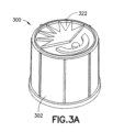
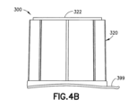
図3A、図3B、および図4〜図7に図示されるような本発明の実施形態の例示的な実施によると、クロススレッドの消毒キャップ300は、ニードルレスコネクタ9の先端部またはハブ12上に嵌合することができ、ならびに閉鎖頂部322、外側側壁表面320を有する本質的に円筒状の側壁304、およびニードルレスコネクタ9の先端部を受け入れるためのハウジング302内部の内部空洞328への開口部326を有する開放底部324、を含むハウジング302を含む。ハウジング302の側壁304によって形成された底部324は、平坦面310とキャップ300の底部324との間に空間370が存在するように、平坦ではない。内部空洞328は、アルコールに浸漬された消毒スポンジ380を収容し、および側壁304の内側側壁表面330上のねじ山(または相手機構)340を有する。キャップ300のねじ山340の直径(大径345および/または小径346)は、ニードルレスコネクタ9のねじ山(または相手機構)13と対応しない。消毒スポンジ380を含む内部空洞328を封止するために、取り外し可能なカバー399をキャップ300の底部324に取り付けることができる。
According to exemplary embodiments of the present invention as illustrated in FIGS. 3A, 3B, and 4-7, the
加えて、図6および図7にさらに図示されるように、例示的な実施によると、キャップ300のねじ山ピッチ、ねじ山区画輪郭、および/またはねじ山の数は、ニードルレスコネクタ9のねじ山13に対応しない。キャップ300のねじ山340はニードルレスコネクタ9のねじ山13に対応しないので、アルコールに浸漬された消毒スポンジ380の通気311は、内部空洞328への1つの開口部326を通って、本質的に、ニードルレスコネクタ9のねじ山13の外部の周囲でおよび空間370を介してキャップハウジング302の外部(atmosphere)に向かって生じる。
In addition, as further illustrated in FIGS. 6 and 7, according to exemplary embodiments, the thread pitch, thread partition contour, and / or number of threads of the
図8Aから図10に図示されるような本発明の実施形態の別の例示的な実施によると、ねじ山大間隙(major gap)消毒キャップ800は、ニードルレスコネクタ9の先端部12上に嵌合することができ、ならびに閉鎖頂部822、外側側壁表面820を有する本質的に円筒状の側壁804、およびニードルレスコネクタ9の先端部を受け入れるためのハウジング802内部の内部空洞828への開口部826を有する開放底部824を含むハウジング802を含む。ハウジング802の側壁804によって形成された底部824は、平坦面810とキャップ800の底部824との間に空間870が存在するように、平坦ではない。内部空洞828は、アルコールに浸漬された消毒スポンジ880を収容し、側壁804の内側側壁表面830上のねじ山840を有する。消毒スポンジ880を含む内部空洞828を封止するために、取り外し可能なカバー899をキャップ800の底部824に取り付けることができる。
According to another exemplary embodiment of the embodiment of the invention as illustrated in FIGS. 8A-10, the major
ねじ山840のピッチは、ニードルレスコネクタ9のねじ山13のピッチに対応する。しかしながら、キャップ800のねじ山840の輪郭(大輪郭841および/または小輪郭842)は、ニードルレスコネクタ9のねじ山13に対応しない。キャップ800のねじ山840はニードルレスコネクタ9のねじ山13に対応しないので、アルコールに浸漬された消毒スポンジ880の通気811は、内部空洞828への1つの開口部826を通って、本質的に、ニードルレスコネクタ9のねじ山13の外部の周囲でおよび空間870を介して、キャップハウジング802の外部(atmosphere)に向かって生じる。
The pitch of the
図11A、図11B、および図12に図示される本発明のまた別の例示的な実施によると、ねじ山キャスタレーション(castellartion)設計の消毒キャップ1100は、ニードルレスコネクタ9の先端部12上に嵌合することができ、ならびに閉鎖頂部1122、外側側壁表面1120を有する本質的に円筒状の側壁1104、およびニードルレスコネクタ9の先端部12を受け入れるためのハウジング1102内部の内部空洞1128への開口部1126を有する開放底部1124を含むハウジング1102を含む。ハウジング1102の側壁1104によって形成された底部1124は、開口部1126がニードルレスコネクタ9の外側表面25と気密封止を形成しないように、ディボット1136を有する不規則な底部内側側壁表面1132を含む。
According to another exemplary practice of the invention illustrated in FIGS. 11A, 11B, and 12, a
例示的な実施において、ハウジング1102は、底部1124に形成されたフレアー状下部1190を含み、これはディボット1136を含む。任意の数の、1つまたは複数のディボット1136が、底部内側側壁表面1132に沿って規則的にまたは無作為に間隔を空けて存在し得る。内部空洞1128は、図10の実施例と同様に、スポンジ1180がニードルレスコネクタ9の少なくとも先端部12と接触しおよびこれを消毒するように、アルコールに浸漬された消毒スポンジ1180を収容する。内部空洞1128は、側壁1104の内側側壁表面1130上のねじ山1140を含む。
In an exemplary embodiment,
ねじ山1140のピッチは、ニードルレスコネクタ9のねじ山13のピッチに対応する。しかしながら、キャップ1100のねじ山1140の輪郭(大輪郭1141および/または小輪郭1142)は、ニードルレスコネクタ9のねじ山13に対応しない。キャップ1100のねじ山1140はニードルレスコネクタ9のねじ山13に対応しないので、アルコールに浸漬された消毒スポンジ1180の通気1111は、本質的に、ニードルレスコネクタ9のねじ山13の外部の周囲で、および内部空洞1128への開口部1126の1つまたは複数のディボット1136を通って、キャップハウジング1102の外部(atmosphere)に向かって生じる。ハウジング1102の側壁1104によって形成された底部1124は、(平坦面810とキャップ800の底部824との間に空間870が存在する図10の例示的な実施形態とは対照的に)本質的に平坦であり得るが、そうである必要はない。消毒スポンジ1180を含む内部空洞1128を封止するために、取り外し可能なカバー1199をキャップ1100の底部1124に取り付けることができる。
The pitch of the
図13、図14Aおよび図14Bに図示されるような本発明の実施形態のその上さらなる例示的な実施によると、延長されたねじ山設計間隙の消毒キャップ1300は、ニードルレスコネクタ9の先端部12上に嵌合することができ、ならびに閉鎖頂部1322、外側側壁表面1320を有する本質的に円筒状の側壁1304、およびニードルレスコネクタ9の先端部を受け入れるためのハウジング1302内部の内部空洞1328への開口部1326を有する開放底部1324を含むハウジング1302を含む。内部空洞1328は、上部領域1312および下部領域1314を含み、ならびにアルコールに浸漬された消毒スポンジ1380を収容する。下部領域1314は、ニードルレスコネクタ9のねじ山13と係合するための側壁1304の内側側壁表面1330上の係合ねじ山1340を含む。ねじ山1340は、延長された部分1348がニードルレスコネクタ9の頂部部分25と接触するようにキャップ1300がコネクタ9上に搭載されたときに、ニードルレスコネクタ9の頂部部分25の表面1310とキャップ1300の底部1324との間に空間1370が存在するように、ハウジング1302の側壁1304によって形成された底部1324の下に延びる延長された部分1348を含む。
According to further exemplary embodiments of embodiments of the invention as illustrated in FIGS. 13, 14A and 14B, the
例示的な実施において、上部領域1312は、消毒スポンジ1380と係合または接触する、側側壁表面1330からの突起1355および/または頂部1322の内側表面からの突起1357を含み得る。係合ねじ山1340のピッチは、ニードルレスコネクタ9のねじ山13のピッチに対応する。しかしながら、キャップ1300の係合ねじ山1340の輪郭(大輪郭1341および/または小輪郭1342)は、ニードルレスコネクタ9のねじ山13に対応しない。キャップ1300の係合ねじ山1340はニードルレスコネクタ9のねじ山13に対応しないので、アルコールに浸漬された消毒スポンジ1380の通気1311は、内部空洞1328への1つの開口部1326を通って、本質的に、ニードルレスコネクタ9のねじ山13の外部の周囲でおよび空間1370を介して、キャップハウジング1302の外部(atmosphere)へ向かって生じる。例示的な実施において、ハウジング1302の側壁1304によって形成された底部1324は、(平坦面810とキャップ800の底部824との間に空間870が存在する図10の例示的な実施形態とは対照的に)本質的に平坦であり得るが、そうである必要はない。消毒スポンジ1380を含む内部空洞1328を封止するために、取り外し可能なカバー1399をキャップ1300の底部1324に取り付けることができる。
In an exemplary embodiment, the
図15から図19に図示されるような本発明の実施形態のまださらなる例示的な実施によると、消毒キャップ1500は、ニードルレスコネクタ9の先端部12上に嵌合することができ、ならびに閉鎖頂部1522、外側側壁表面1520を有する側壁1504、およびニードルレスコネクタ9の先端部を受け入れるためのハウジング1502内部の内部空洞1528に対する開口部1526を有する開放底部1524を含むハウジング1502を含む。内部空洞1528は、上部領域1512および下部領域1514を含み、ならびにアルコールに浸漬された消毒スポンジ1580を収容する。ハウジング1502の側壁1504によって形成された底部1524は、コネクタ9の先端部が少なくとも空洞1528の下部領域1514内部と確実に係合しているときに開口部1526がニードルレスコネクタ9の外側表面25と気密封止を形成しないように、内側側壁表面1532を有するフレアー状底部部分1590を含む。消毒スポンジ1580を含む内部空洞1528を封止するために、取り外し可能なカバー1599をキャップ1500の底部1524に取り付けることができる。
According to still further exemplary embodiments of embodiments of the invention as illustrated in FIGS. 15-19, the
例示的な実施において、内側側壁表面1532によって形成された内部空洞1528への開口部1526は、本質的に円形であり、および、開口直径26が内側側壁表面1532とニードルレスコネクタ9の外側表面25との間に通気間隙1527をもたらすように、ニードルレスコネクタ9の外側表面25のフランジ直径1533よりも大きい開口直径26を有する。
In an exemplary embodiment, the
下部領域1514は、ニードルレスコネクタ9のねじ山13と係合するための側壁1504の内側側壁表面1530上のねじ山1540を含む。例示的な実施において、上部領域1512は、消毒スポンジ1580と係合または接触する、内側側壁表面1530上の突起1555および/または(図13の実施例において図示される突起1357のような)頂部1522の内側表面上の突起(不図示)を含み得る。
The
ねじ山1540のピッチは、ニードルレスコネクタ9のねじ山13のピッチに対応する。しかしながら、キャップ1500のねじ山1540の輪郭(大輪郭1541および/または小輪郭1542)は、ニードルレスコネクタ9のねじ山13に対応しない。キャップ1500の係合ねじ山1540はニードルレスコネクタ9のねじ山13に対応しないので、アルコールに浸漬された消毒スポンジ1580の通気1511は、本質的に、ニードルレスコネクタ9のねじ山13の外部の周囲でおよび内部空洞1528への開口部1526を通って、キャップハウジング1502の外部(atmosphere)に向かって生じる。例示的な実施において、通気1511は、開口部1526を通って通気間隙1527を介して生じる。
The pitch of the
ハウジング1502の側壁1504によって形成される底部1524は、(平坦面810とキャップ800の底部824との間に空間870が存在する図10の例示的な実施形態とは対照的に)本質的に平坦であり得るが、そうである必要はない。
The bottom 1524 formed by the
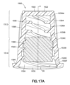
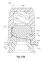
図17A、図17Bおよび図17Cに図示されるような本発明の実施形態の例示的な実施によると、キャップ1500の下部領域1514における内側側壁表面1530は、本質的にねじ山1540間に区画1530C、1530D、1530E、および1530Fを含むことができ、各区画は、長手方向軸Aに関して傾斜を有する。さらなる実施例的な実施において、区画1530Eおよび1530F内の内側側壁表面1530は、長手方向軸Aから離れて広がりフレアー状に広がる開口部1526を形成する。まださらなる例示的な実施において、区画1530Cの頂部における内側エリアは、開口部1526を形成する区画1530Fの底部におけるエリアよりも小さくてもよい。なおさらなる例示的な実施において、区画1530Dの頂部におけるエリアを、図16の実施例において図示されるように、空洞1528内へのニードルレスコネクタ9のさらなる挿入を妨げるように、ニードルレスコネクタ9の先端部12が本質的に区画1530Dの頂部において停止するように、構成することができる。
According to an exemplary embodiment of the invention as illustrated in FIGS. 17A, 17B and 17C, the inner
まださらなる例示的な実施において、キャップ1500の上部領域1512における内側側壁表面1530は、本質的に突起1555間に、区画1530AAおよび1530Aを含むことができ、各区画は、長手方向軸Aに関して傾斜を有する。なおさらなる例示的な実施において、内側側壁表面1530は、領域1514における区画1530Bの底部におけるエリアが領域1512における区画1530Bの頂部におけるエリアよりも大きくなるように内側側壁表面1530が下部領域1514から上部領域1512に移行する直線状の(図19の実施例参照)または湾曲した(図17A、図17B、図17Cおよび図18の実施例参照)表面を有する移行区画1530Bを含むことができる。突起1555および/または区画1530Bの頂部におけるより小さいエリアは、コネクタ9の先端部12がキャップ1500の空洞1528内部に固定されたときに、空洞1528の、ある領域内部、例えば本質的に区画1530Bおよび1530C内部内で、スポンジ1580が圧縮および/または保持され得るように、キャップ1500がニードルレスコネクタ9と係合するときにスポンジ1580が上部領域1512内に移動させられるのを防止することができる。
Yet in further exemplary implementation, the
図18に図示されるような本発明の実施形態のまださらなる例示的な実施において、キャップ1500の下部領域1514における内側側壁表面1530は、本質的にねじ山1540間の区画1530C、1530Dおよび1530E、ならびに最も底部の区画としての区画1530F、または区画1530Fの下方の開口段(aperture step)を含むことができる。全ての区画は、本質的に、長手方向軸Aに関して同一の傾斜または角度を有する。しかしながら、図19に図示される例示的な実施とは異なり、区画1530C、1530D、1530Eおよび/または1530Fは、共線的ではない。
In a still further exemplary embodiment of the embodiment of the invention as illustrated in FIG. 18, the inner
図19に図示されるような本発明の実施形態のまださらなる例示的な実施において、キャップ1500の下部領域1514における内側側壁表面1530は、長手方向軸Aに関して本質的に同一の傾斜または角度を有する本質的にねじ山1540全区画間に、本質的に共線的1531区画1530C、1530Dおよび1530Eを含み得る。しかしながら、図18に図示された例示的な実施とは異なり、区画1530Fを、区画1530Eの一体的な最も底部の部分として構成することができる。
In a still further exemplary embodiment of the embodiment of the invention as illustrated in FIG. 19, the inner
まだ別の例示的な実施において、キャップ1500は、例えば、カバー1599を取り外し、ニードルレスコネクタ9と係合させおよび/またはニードルレスコネクタ9と係合解除させるようにキャップ1500を取り扱うようなときに、キャップ1500のよりよい握りを容易にするために、ハウジング1502の外側側壁表面1520上に形成されたリッジ1598を含む。
In yet another exemplary embodiment, when the
図20A、図20B、および図20Cに図示されるような本発明の実施形態のまださらなる例示的な実施によると、消毒キャップ2000は、ニードルレスコネクタ9の先端部12上に嵌合するとができ、ならびに閉鎖頂部2022、外側側壁表面2020を有する側壁2004、およびニードルレスコネクタ9の先端部を受け入れるためのハウジング2002内部の内部空洞2028への開口部2026を有する開放底部2024、を含むハウジング2002を含む。内部空洞2028は、アルコールに浸漬された消毒スポンジ2080を収容する。ハウジング2002の側壁2004によって形成された底部2024は、コネクタ9の先端部が空洞2028内部と確実に係合しているときに開口部2026がニードルレスコネクタ9の外側表面25と気密封止を形成しないように、内側側壁表面2032を有する底部部分2090を含む。図15の実施例におけるように、消毒スポンジ2080を含む内部空洞2028を封止するために、1599のような取り外し可能なカバーをキャップ2000の底部2024に取り付けることができる。
According to still further exemplary embodiments of embodiments of the invention as illustrated in FIGS. 20A, 20B, and 20C, the
例示的な実施において、内側側壁表面2032によって形成された内部空洞2028への開口部2026は、本質的に円形であり、および開口直径2026Aが内側側壁表面2032とニードルレスコネクタ9の外側表面25との間に通気間隙2027をもたらすように、ニードルレスコネクタ9の外側表面25のフランジ直径2033よりも大きい開口直径2026Aを有する。
In the exemplary, the
内部空洞2028は、ニードルレスコネクタ9のねじ山13と係合するために、側壁2004の内側側壁表面2030上のねじ山2040を含む。例示的な実施において、ねじ山2040の少なくとも部分は、ニードルレスコネクタ9のねじ山13とのより確実な係合を容易にするための突起2040Aを含むことができる。
The
ねじ山2040のピッチは、ニードルレスコネクタ9のねじ山13のピッチに対応する。しかしながら、キャップ2000のねじ山2040の輪郭(大輪郭2041および/または小輪郭2042)は、ニードルレスコネクタ9のねじ山13に対応しない。キャップ2000の係合ねじ山2040はニードルレスコネクタ9のねじ山13に対応しないので、アルコールに浸漬された消毒スポンジ2080の通気2011は、本質的に、ニードルレスコネクタ9のねじ山13の外部の周囲でおよび内部空洞2028への開口部2026を通って、キャップハウジング2002の外部(atmosphere)へ向かって生じる。例示的な実施において、通気2011は、開口部2026を通って通気間隙2027を介して生じる。消毒スポンジ2080を含む内部空洞2028を封止するために、取り外し可能なカバー2099をキャップ2000の底部2024に取り付けることができる。
The pitch of the
図20Aに図示されるような本発明の実施形態の例示的な実施によると、キャップ2000の内側側壁表面2030は、本質的にねじ山2040間に2030Aのような区画を含むことができ、各区画は、長手方向軸Aに関して本質的に同一の傾斜を有する。
According to an exemplary embodiment of the embodiment of the invention as illustrated in FIG. 20A, the
図21A、図21B、および図21Cに図示されるような本発明の実施形態のまださらなる例示的な実施によると、消毒キャップ2100は、ニードルレスコネクタ9の先端部12上に嵌合することができ、ならびに閉鎖頂部2122、外側側壁表面2120を有する側壁2104、およびニードルレスコネクタ9の先端部を受け入れるためのハウジング2102内部の内部空洞2128への開口部2126を有する開放底部2124、を含むハウジング2102を含む。内部空洞2128は、アルコールに浸漬された消毒スポンジ2180を収容する。ハウジング2102の側壁2104によって形成された底部2124は、コネクタ9の先端部が空洞2128内部と確実に係合しているときに開口部2126はニードルレスコネクタ9の外側表面25と気密封止を形成しないように内側側壁表面2132を有する底部部分2190を含む。消毒スポンジ2180を含む内部空洞2128を封止するために、図15の実施例におけるように、1599のような取り外し可能なカバーをキャップ2100の底部2124に取り付けることができる。
According to still further exemplary embodiments of embodiments of the invention as illustrated in FIGS. 21A, 21B, and 21C, the
例示的な実施において、内側側壁表面2132によって形成された内部空洞2128への開口部2126は、本質的に円形であり、および開口直径2126Aが内側側壁表面2132とニードルレスコネクタ9の外側表面25との間に通気間隙2127をもたらすように、ニードルレスコネクタ9の外側表面25のフランジ直径2133よりも大きい開口直径2126Aを有する。
In the exemplary, the
内部空洞2128は、側壁2104の内側側壁表面2130上に、ニードルレスコネクタ9のねじ山13と係合するための、ねじ山2140を含む。例示的な実施において、ねじ山2140の少なくとも部分は、ニードルレスコネクタ9のねじ山13とのより確実な係合を容易にするための突起2140Aを含むことができる。
The
ねじ山2140のピッチは、ニードルレスコネクタ9のねじ山13のピッチに対応する。しかしながら、キャップ2100のねじ山2140の輪郭(大輪郭2141および/または小輪郭2142)は、ニードルレスコネクタ9のねじ山13に対応しない。キャップ2100の係合ねじ山2140はニードルレスコネクタ9のねじ山13に対応しないので、アルコールに浸漬された消毒スポンジ2180の通気2111は、本質的に、ニードルレスコネクタ9のねじ山13の外部の周囲でおよび内部空洞2128への開口部2126を通って、キャップハウジング2102の外部(atmosphere)へ向かって生じる。例示的な実施において、通気2111は、開口部2126を通って通気間隙2027を介して生じる。
The pitch of the
例示的な実施において、内部空洞2128は、ねじ山2140よりも小さい輪郭を有しおよび例えば摩擦嵌合の方法でニードルレスコネクタ9のねじ山13と係合しない、側壁2104の内側側壁表面2130上のねじ山2143を含む。消毒スポンジ2180を含む内部空洞2128を封止するために、取り外し可能なカバー2199をキャップ2100の底部2124に取り付けることができる。
In an exemplary embodiment, the
図21Cに図示されるようなまだ別の例示的な実施においておよび図17Cの例示的な実施形態と同様に、キャップ2100は、例えば、カバー1599を取り外しニードルレスコネクタ9と係合させおよび/またはニードルレスコネクタ9と係合解除させるようにキャップ2100を取り扱うようなときに、キャップ2100のよりよい握りを容易にするために、ハウジング2102の外側側壁表面2120上に形成されたリッジ2198を含む。
In yet another exemplary embodiment as illustrated in FIG. 21C and as in the exemplary embodiment of FIG. 17C, the
図23Aおよび図23Bは、ニードルレスコネクタ93の先端部を受け入れる本発明の実施形態の例示的な実施による消毒キャップ3000を図示し、それは注釈が加えられた図22に示されるように国際規格ISO594−2:1998(E)に従って構成された外部ねじ山113を備える雌6%(ルアー)ロックコニカルフィッティングであり、そこで、αは、非限定的な例示的な方法でコネクタねじ山α機構133Aと呼ばれ得る、ロックフィッティングの軸と垂直な平面との分離に対するねじ山またはラグ支持面角度であり、γは、ロックフィッティングの軸と垂直な平面との分離に対する外部ねじ山またはラグ非支持面の最小角度であり、2Xは、非限定的な例示的な方法でコネクタねじ山大機構133Bと呼ばれ得る、ラグまたは外部ねじ山を横断する外径であり、Eは、雄ロックフィッティングの最小長であり、Gは、ラグの基部における雌ロックフィッティングの最大外径または外部ねじ山の最大内径であり、Sは、ラグまたは外部ねじ山を有する雌ロックフィッティングのラグ山幅またはねじ山山幅であり、Yは、Gに等しい外径に対応する点で測定されるべき雌ロックフィッティングの(軸方向の)ラグの基部または基部におけるねじ山の最大幅である。
23A and 23B illustrate a
図23Aの横断面図および図23Bの三次元図を参照して、消毒キャップ3000は、閉鎖頂部3022、外側側壁表面3020を有する側壁3004、およびニードルレスコネクタ93を受け入れるためのハウジング3002内部の内部空洞3028への開口部3026を有する開放底部3024、を含むハウジング3002を含む。内部空洞3028は、アルコールに浸漬された消毒スポンジ3080を収容し得るが、そうである必要はない。図15の実施例におけるように、1599のような取り外し可能なカバーを、その中に配置される消毒スポンジ3080を伴って、または伴わずに(図23Bに示されるように)、内部空洞3028を封止するように、キャップ3000の底部3024に取り付けることができる。
With reference to the cross-sectional view of FIG. 23A and the three-dimensional view of FIG. 23B, the
キャップ3000の内部空洞3028は、その側壁3004の内側側壁表面3030上の1つまたは複数のねじ山(バンプ、ラグ、またはリブ)3040、3042を含む。例示的な実施において、ねじ山3040のような、少なくとも1つのねじ山の少なくとも部分またはねじ山全体は、ねじ山3040から空洞3028内に延びるさらなる突起(バンプ、ラグ、またはリブ)3040Aを含み得る。突起3040Aは、キャップ3000の空洞3028内部のコネクタ93の係合を容易にするために、コネクタ93のねじ山133の少なくとも部分、例えば、コネクタねじ山α機構133Aの部分および/またはコネクタねじ山大機構133Bの部分と係合可能に相互作用する。
The
例示的な実施において、側壁3004の内側側壁表面3030上のねじ山3042は、ねじ山3040よりも小さい輪郭を有し、および例えば摩擦嵌合の方法で、コネクタ93のねじ山133と係合しない。ねじ山3040および3042は、その上にねじ山3040および/または3042の選択的に形成された機構を備える単一の連続的なまたは部分的なねじ山として、または例えば180度または90度で(例えば、図24Aから図24Iに図示されるように)交互に並ぶ連続的または部分的なねじ山として、形成され得る。
In an exemplary embodiment, the
別のまたは付加的な例示的な実施において、さらなる突起を有さないねじ山3042のようなねじ山(単数または複数)は、例えば図23Aおよび図23Bに図示されるように、コネクタ93上にキャップ3000を配置するときまたはキャップ3000の空洞3028内にコネクタ93を挿入するときに、コネクタ93とのキャップ3000の軸方向位置合わせを容易にすることができる。例示的な実施において、空洞3028内部のねじ山3040の大輪郭は、本質的に厳密にまたは所与の許容差内でコネクタ93のねじ山大機構133Bに対応しまたは一致し得る。換言すれば、ねじ山3042は、その表面接触部分で本質的に接線方向にねじ山133と相互作用する。例えば、キャップ3000の円筒状の実施形態において、ねじ山3042は、本質的に接触直径で、ねじ山133と触れ合い得る。
In another or additional exemplary embodiment, threads (s) such as
キャップ3000および空洞3028が頂部3022に存在するより大きい横断面を有する本質的に円錐台状である例示的な実施において、図23Aの実施例において示されるように、係合ねじ山3040は、それが空洞3028内に進むにつれて、コネクタ93のより確実な係合を提供することができる。非係合ねじ山3042は、例えば、空洞3028内部のコネクタ93のさらなる位置合わせまたは保持を容易にするために、干渉嵌合を提供することができる。
In an exemplary embodiment in which the
まだ別のまたは付加的な例示的な実施において、キャップ3000のねじ山3040および/または3042のピッチおよび/または輪郭は、コネクタ93のねじ山133のピッチおよび/または輪郭に対応しない。したがって、キャップ3000の空洞3028内の通気は、コネクタ93が空洞3028内側にあるときに、本質的に、ねじ山133の外部の周囲で生じる。
In yet another or additional exemplary practice, the pitch and / or contour of the
なお別のまたは付加的な例示的な実施において、ねじ山3040のピッチは、コネクタ93のねじ山133のピッチに対応する。しかしながら、ねじ山3040の輪郭は、ねじ山133に対応しない。係合ねじ山3040はねじ山133に対応しないので、内部空洞3028内の通気は、コネクタ93が内部空洞3028の内側にあるときに、本質的に、ねじ山133の外部の周囲で生じる。
In yet another or additional exemplary practice, the pitch of the
図24Aに図示されたようなまだ別の例示的な実施においてならびに図17Cおよび図21Bの例示的な実施形態と同様に、キャップ3000は、例えば、キャップ3000を取り扱い、コネクタ93を(空洞3028内に)係合させ、および/またはコネクタ93を(空洞3028から)係合解除するようなときにキャップ3000のよりよい握りを容易にするために、ハウジング3002の外側側壁表面3020上に形成されたリッジ3098を含む。
In yet another exemplary embodiment as illustrated in FIG. 24A and as in the exemplary embodiments of FIGS. 17C and 21B, the
図24Aから図24Iを参照して、本発明の実施形態の例示的な実施は、消毒キャップ3000の様々な構成要素の、ある寸法的特性の観点から記載される。図24Aから図24Iに提示される相対的および具体的な数値特性の両方は、特許請求の範囲に示される際の本発明の範囲を限定することなく、本発明の実施形態の例示的な実施のより完全な理解をよいにすることが意図される。図15の実施例におけるように、1599のような取り外し可能なカバーを、その中に配置される消毒スポンジ3080を伴って、または伴わずに(図24A〜図24Iに示されるように)、内部空洞3028を封止するように、キャップ3000の底部3024に取り付けることができる。
With reference to FIGS. 24A to 24I, exemplary embodiments of embodiments of the invention are described in terms of certain dimensional properties of the various components of the
図24Aは、異なる眺望から、キャップ3000の頂部3022を示す角度から(図中左)およびキャップ3000の底部3024を示す角度から(図中右)、のキャップ3000の三次元図を示す。図24Bは、本発明の実施形態の例示的な実施によるキャップ3000の本体3002の6度の円錐台状の構成を図示するキャップ3000の側面図を示す。図24Cは、頂部3022からのキャップ3000の図である。図24Dは、底部3024からのキャップ3000の図であり、これは、内部空洞3028への開口部3026、ねじ山3040/3042も示し、およびそれぞれ図24E、図24Fおよび図24Hに図示されるキャップ3000の横断面図の表示AC−AC、D−D、およびE−Eを含む。例示的な実施において、キャップ3000は、底部3024に形成されたキャップ3000を製造するときに射出成型のために使用される抗回転性のラグであるディボット2499を含むことができる。
FIG. 24A shows a three-dimensional view of the
図24Eは、開口部3026およびねじ山ピッチならびに(もしキャップ3000の底部3024に形成されたならば)ディボット2499を含むキャップ本体3002の相対的寸法特性を示す、キャップ3000の横断面図AC−AC(図24D参照)である。図24Fは、開口部3026およびねじ山ピッチ、ならびに頂部3022の機構およびねじ山3040の細部Bを含むキャップ本体3002の相対的寸法特性を同様に示すキャップ3000の横断面図D−D(図24D参照)である。図24Hは、開口部3026およびねじ山ピッチならびに内部空洞3028の円錐台状の構成、底部3024のリップ機構、およびねじ山3042の細部Aを含むキャップ本体3002の相対的寸法特性をさらに示すキャップ3000の横断面図E−E(図24D参照)である。
FIG. 24E is a cross-sectional view of the
図24Gは、本発明の実施形態の例示的な実施によるねじ山3040の具体的な相対的寸法特性の拡大横断面図B(図24F参照)である。図24Iは、本発明の実施形態の例示的な実施によるねじ山3042の具体的な相対的寸法特性の拡大横断面図A(図24H参照)である。図24Gおよび図24Iの実施例に示されるように、ねじ山3040およびねじ山3042は、実質的に同様のそれぞれの谷区画輪郭3040Rおよび3042R、ならびに実質的に異なる山区画輪郭3040Cおよび3042Cを有し得る。
FIG. 24G is an enlarged cross-sectional view B (see FIG. 24F) of the specific relative dimensional characteristics of the
図25Aおよび図25Bを参照して、本発明の例示的な実施形態による分配デバイス2260は、ミシン目が入れられたストリップ2220上に配置された複数のキャップ2230を含む。例示的な実施において、ミシン目2270は、ストリップ2220上に配置されたキャップ2230間に形成されて、その上に配置された少なくとも1つのキャップ2230を有するストリップ2220の部分2272を画定する。キャップ2230は、図1A、図1Bおよび図3Aから図21Cの実施例において図示されならびにそれらを参照して上述されたキャップのうちのいずれかのように構造的および機能的に構成され得る。例示的な実施において、ストリップ2220は、例えば、図1A、図1B、図4B、図8B、図11B、図14B、図15、図20B、図21B、図25Aを参照して上述されるように、各キャップ2230の内部空洞を封止するために各キャップ2230の底部に取り付けられるキャップカバーとして構成されたピールストリップであり得る。
With reference to FIGS. 25A and 25B, the
図25Aの実施例において図示されるように、即時の使用のために、例えば、ニードルレスコネクタをキャップするために、各キャップ2230をストリップ2220から剥がしまたは分離することができる。他方、図25Bの実施例において図示されるように、その上に配置されたキャップ2230を含む部分2272を、キャップ2230の内部空洞が図1A、図1B、図4B、図8B、図11B、図14B、図15、図20B、および図21Bの実施例において図示される個々のキャップと同様に部分2272によって封止されたままであるように、ストリップから選択的に分離することができる。
As illustrated in the embodiment of FIG. 25A, each
本発明の例示的な実施形態によると、分配デバイス2260は、図25Aおよび図25Bに示されるようにキャップ2230の単一の列を有するミシン目が入れられたストリップ2220、またはそのような実施の上面図を示す図25Cの実施例に例示されるようにミシン目2273によって分離されるキャップ2230の多数の列を有するミシン目が入れられたストリップ2250、を有するように構成され得る。図25Dの側面図に図示されるようなまだ別の例示的な実施形態によると、分配デバイス2260は、2つの封止されたキャップ2230を後の使用のためにミシン目2275においてストリップ2255から選択的に切り離す(図25D参照)および/または即時の使用のためにストリップ2255の両側から個々に取り外す(図25D参照)ことができるように、2つの対向側面2265および2267を有する両面型のミシン目が入れられたピールストリップ2255、ならびにその両側において取り付けられたキャップ2230、を有するように構成され得る。
According to an exemplary embodiment of the invention, the
図25A、図25B、図25C、および図25Dに図示されるように、ストリップ2220/2250/2255は、本質的に平坦であり、および各キャップ2230中間にミシン目を有する。したがって、各ミシン目が入れられたキャップストリップ区画を、後の使用のためにキャップ2230を剥がして開けることができるように、主ストリップからちぎりまたは切り離すことができる(図25B参照)。または、代替的に、即時の使用のために、各キャップをキャップストリップから剥がして開くことができる(図25A参照)。
As illustrated in FIGS. 25A, 25B, 25C, and 25D, the
例示的な実施において、ストリップ2220/2250/2255は、例えば、デバイス2260を便利のためにIVポール上に吊るすことができるようにIVポールのハンガーを収容するために、その少なくとも1つの端部に開口部2240のような取り付け部分を含む。フックまたは同種のもののような、取り付け部分の他のバリエーション、またはIVポール上にストリップ2220/2250/2255を選択的に配置するまたは吊るすための手段は、当業者によって容易に認識されるように、ストリップ2220/2250/2255に一体化されまたは取り付けられ得る。
In an exemplary embodiment, the
図26Aおよび図26Bを参照して、本発明の例示的な実施形態による分配デバイス2360は、例えば、頂部フック2340またはIVポール上にストリップを選択的に配置するまたは吊るすための他の手段のような取り付け部分を含む射出成型されたランナーバーのような任意の形状であり得る吊るし用ストリップ2320上に配置される複数のキャップ2330を含む。キャップ2330は、図1A、図1Bおよび図3Aから図21Cの実施例において図示されならびにそれらを参照して上述されたキャップのうちのいずれかのように構造的および機能的に構成され得る。例示的な実施によると、各キャップ2330は、例えば、図1A、図1B、図4B、図8B、図11B、図14B、図15、図20B、および図21Bの実施例において図示された個々のキャップと同様に、ピールストリップ2372で封止される。
With reference to FIGS. 26A and 26B, the
さらに例示的な実施において、各キャップ2330は、例えば、ストリップ2320の表面に取り付けられおよびそこから延びるプロング2380によって、ストリップ2320に取り付けられている。例示的な実施において、プロング2380は、各キャップ2330を(例えば、キャップの頂部の外面において)主射出成型ランナーバーとして構成されたストリップ2320と接続するランナーゲートプロングとして構成される。図26Aの実施例において図示されるように、プロング2380から引き千切られまたは切り離されたキャップ2330は、それが後刻において使用され得るように、キャップに依然として付着したピールフィルム2372を有する。
In a more exemplary embodiment, each
図26Bの実施例において図示されるようなまだ別の例示的な実施において、分配デバイス2360は、例えば2つのキャップ2330をストリップ2372上の本質的に同一の長手方向の場所においてストリップ2372に取り付けることができるように、その直径方向反対側においてストリップ2372に取り付けられる多数のプロング2380を有し得る。そのような構成は、例えば、同一長のストリップに取り付けられる2倍の数のキャップを可能にし得る。
In yet another exemplary embodiment as illustrated in the embodiment of FIG. 26B, the
本発明は、その特定の例示的な実施形態を参照して示されおよび記載されてきたが、本発明の実施形態の精神および範囲から逸脱することなく形態および詳細における様々な変更が加えられてもよいことは、当事者によって理解されよう。例えば、消毒スポンジは、任意の適当な消毒用または他の特定用途向け物質を含むことができ、および任意の適当な材料で作製され得る。また、キャップを、シングルショット成型することができ、または他の適当な工程によって作製することができる。 The invention has been shown and described with reference to its particular exemplary embodiments, with various modifications in form and detail without departing from the spirit and scope of the embodiments of the invention. It will be understood by the parties that it is good. For example, the disinfectant sponge can contain any suitable disinfectant or other specific purpose substance and can be made of any suitable material. Also, the cap can be single-shot molded or made by other suitable steps.
加えて、含まれた作図図面は、本発明の特定の例示的な実施形態の実施の非制限的な実施例をさらに表現し、およびそれに関連する技術の説明に役立つ。上述のような他の図面に提供される任意の具体的または相対的な寸法または大きさは、例示的であり、および発明の関連分野における熟練工によって理解されるような発明の設計または方法の範囲または内容を制限することを意図するものではない。 In addition, the included drawing drawings further represent non-limiting examples of the implementation of certain exemplary embodiments of the invention and serve to illustrate the techniques associated therewith. Any specific or relative dimensions or sizes provided in other drawings as described above are exemplary and the scope of the design or method of the invention as understood by skilled workers in the relevant field of the invention. Or it is not intended to limit the content.
本発明の他の目的、利点および目立った特徴は、添付された作図図面と共に用いられ本発明の例示的な実施形態を開示する提示された詳細から、当業者にとって明らかになるであろう。 Other objects, advantages and salient features of the invention will be apparent to those skilled in the art from the presented details used with the accompanying drawing drawings and disclosing exemplary embodiments of the invention.
Claims (11)
少なくとも第2の開始ねじ山経路であって、第2の大輪郭、第2の小輪郭、第2のピッチ、および第2のねじ山区画輪郭を有する第2の開始ねじ山経路、
を含み、
前記第1のねじ山区画輪郭および前記第2のねじ山区画輪郭は異なっており、
前記第1のねじ山区画輪郭および前記第2のねじ山区画輪郭は雌ねじ山パターンを形成し、
前記第1および第2の開始ねじ山経路は、二次的な医療用デバイスコネクタの補完雄ねじ山と相互作用するように構成されており、前記補完雄ねじ山は、一様な外径を有する第3の大輪郭、第3の小輪郭、および前記第1のピッチと実質的に同等の第3のピッチを有し、ならびに
少なくとも前記第1の開始ねじ山経路が、前記第3の大輪郭と接する前記補完雄ねじ山と係合するとき、第1のらせん状空所は、前記第1の開始ねじ山経路と、前記補完雄ねじ山の前記第3の大輪郭および前記第3の小輪郭のうちの少なくとも一方と、によって取り囲まれた空間によって形成されることを特徴とする、医療用デバイスコネクタにおける使用のための複数の開始ねじ山パターン。 A first starting thread path, the first starting thread path having a first large contour, a first small contour, a first pitch, and a first thread partition contour.
A second starting thread path having at least a second starting thread path with a second large contour, a second small contour, a second pitch, and a second thread section contour.
Including
The first thread section contour and the second thread section contour are different .
The first thread section contour and the second thread section contour form a female thread pattern.
The first and second starting thread paths are configured to interact with complementary male threads of a secondary medical device connector, the complementary male threads having a uniform outer diameter. It has a large contour of 3, a third minor contour, and a third pitch that is substantially equivalent to the first pitch, and
When at least the first starting thread path engages the complementary male thread that is in contact with the third major contour, the first spiral void is the first starting thread path and the complement. Multiple initiations for use in medical device connectors, characterized by being formed by a space enclosed by at least one of the third major contour and the third minor contour of the male thread. Thread pattern.
少なくとも第2の開始ねじ山経路であって、第2の大輪郭、第2の小輪郭、第2のピッチ、および第2のねじ山区画輪郭を有する、第2の開始ねじ山経路、
を含む、複数の開始ねじ山パターンと、
前記第1および第2の開始ねじ山経路、閉鎖端、および二次的な医療用デバイスコネクタを受け入れるように構成された前記閉鎖端の反対側の開放端を有する内側表面を含む内部空洞と、
を含む複数の開始ねじ山パターンを含むキャップであって、
前記第1のねじ山区画輪郭および前記第2のねじ山区画輪郭は異なっており、
前記第1のピッチおよび前記第2のピッチは実質的に同等であり、
前記第1および第2の開始ねじ山経路は前記二次的医療用デバイスコネクタの補完雄ねじ山と相互作用するように構成されており、前記補完雄ねじ山は一様な外径を有する第3の大輪郭、第3の小輪郭、および前記第1および第2の開始ねじ山経路の前記第1および第2のピッチと実質的に同等の第3のピッチを有し、ならびに
前記補完雄ねじ山が、前記第3の大輪郭と接する前記第1および第2の開始ねじ山経路と係合するとき、第1のらせん状空所は、前記補完雄ねじ山の前記第3の大輪郭および前記第3の小輪郭のうちの少なくとも一方と、前記第1の開始ねじ山経路と、によって取り囲まれた空間によって形成され、および前記第2のらせん状空所は、前記補完雄ねじ山の前記第3の大輪郭および前記第3の小輪郭のうちの少なくとも一方と、前記第2の開始ねじ山経路と、によって取り囲まれた空間によって形成され、前記第2のらせん状空所は、前記第1のらせん状空所よりも大きく、ならびに
前記キャップの近位端から前記内部空洞への空気流経路は、前記補完雄ねじ山が前記複数の開始ねじ山パターンと係合するときに、前記第1および第2のらせん状空所によって形成されることを特徴とするキャップ。 A first starting thread path and a first starting thread path having a first large contour, a first small contour, a first pitch, and a first thread partition contour.
A second starting thread path, which is at least a second starting thread path and has a second large contour, a second small contour, a second pitch, and a second thread partition contour.
With multiple starting thread patterns, including
An internal cavity including an inner surface having an open end opposite the closed end, configured to accommodate the first and second starting thread paths, a closed end, and a secondary medical device connector.
A cap containing multiple starting thread patterns, including
The first thread section contour and the second thread section contour are different.
The first pitch and the second pitch are substantially equivalent.
The first and second starting thread paths are configured to interact with the complementary thread of the secondary medical device connector, the complementary thread having a uniform outer diameter of the third. It has a large contour, a third minor contour, and a third pitch that is substantially equivalent to the first and second pitches of the first and second starting thread paths, and
When the complementary male thread engages with the first and second starting thread paths in contact with the third large contour, the first spiral void is the third large of the complementary male thread. The space is formed by the contour and at least one of the third minor contours and the first starting thread path, and the second spiral void is of the complementary male thread. The second spiral void is formed by a space surrounded by at least one of the third major contour and the third minor contour, and the second starting thread path. greater than the first spiral space, and the air flow path to the interior cavity from the proximal end of said cap when said complementary male thread engaging said multiple start threads pattern, wherein A cap characterized by being formed by a first and second spiral void.
Priority Applications (1)
| Application Number | Priority Date | Filing Date | Title |
|---|---|---|---|
| JP2021196245A JP7136990B2 (en) | 2016-01-18 | 2021-12-02 | Method for connecting first medical device connector and second medical device connector |
Applications Claiming Priority (5)
| Application Number | Priority Date | Filing Date | Title |
|---|---|---|---|
| US201662279986P | 2016-01-18 | 2016-01-18 | |
| US62/279,986 | 2016-01-18 | ||
| US201662300247P | 2016-02-26 | 2016-02-26 | |
| US62/300,247 | 2016-02-26 | ||
| PCT/US2017/013790 WO2017127365A1 (en) | 2016-01-18 | 2017-01-17 | Disinfection cap for iv needleless connectors |
Related Child Applications (1)
| Application Number | Title | Priority Date | Filing Date |
|---|---|---|---|
| JP2021196245A Division JP7136990B2 (en) | 2016-01-18 | 2021-12-02 | Method for connecting first medical device connector and second medical device connector |
Publications (3)
| Publication Number | Publication Date |
|---|---|
| JP2019501741A JP2019501741A (en) | 2019-01-24 |
| JP2019501741A5 JP2019501741A5 (en) | 2020-02-20 |
| JP6989508B2 true JP6989508B2 (en) | 2022-01-05 |
Family
ID=59314991
Family Applications (5)
| Application Number | Title | Priority Date | Filing Date |
|---|---|---|---|
| JP2018537466A Active JP6989508B2 (en) | 2016-01-18 | 2017-01-17 | Disinfection cap for IV needleless connectors |
| JP2018537458A Active JP7071267B2 (en) | 2016-01-18 | 2017-01-17 | Disinfection cap for IV needleless connector |
| JP2021196245A Active JP7136990B2 (en) | 2016-01-18 | 2021-12-02 | Method for connecting first medical device connector and second medical device connector |
| JP2022076670A Active JP7469364B2 (en) | 2016-01-18 | 2022-05-06 | Device Including Disinfecting Cap for IV Needleless Connector - Patent application |
| JP2022139239A Active JP7444938B2 (en) | 2016-01-18 | 2022-09-01 | A device comprising a strip and a cap attached to the strip that includes a plurality of starting thread patterns and an internal cavity. |
Family Applications After (4)
| Application Number | Title | Priority Date | Filing Date |
|---|---|---|---|
| JP2018537458A Active JP7071267B2 (en) | 2016-01-18 | 2017-01-17 | Disinfection cap for IV needleless connector |
| JP2021196245A Active JP7136990B2 (en) | 2016-01-18 | 2021-12-02 | Method for connecting first medical device connector and second medical device connector |
| JP2022076670A Active JP7469364B2 (en) | 2016-01-18 | 2022-05-06 | Device Including Disinfecting Cap for IV Needleless Connector - Patent application |
| JP2022139239A Active JP7444938B2 (en) | 2016-01-18 | 2022-09-01 | A device comprising a strip and a cap attached to the strip that includes a plurality of starting thread patterns and an internal cavity. |
Country Status (13)
| Country | Link |
|---|---|
| US (6) | US11083883B2 (en) |
| EP (3) | EP4088748A1 (en) |
| JP (5) | JP6989508B2 (en) |
| KR (2) | KR20180102162A (en) |
| CN (6) | CN114392475A (en) |
| AU (5) | AU2017208921B2 (en) |
| BR (1) | BR112018014473B1 (en) |
| CA (3) | CA3010519C (en) |
| DK (1) | DK3258971T3 (en) |
| ES (1) | ES2927781T3 (en) |
| MX (4) | MX2018008750A (en) |
| SG (4) | SG11201805607YA (en) |
| WO (2) | WO2017127365A1 (en) |
Families Citing this family (76)
| Publication number | Priority date | Publication date | Assignee | Title |
|---|---|---|---|---|
| USD1002840S1 (en) * | 2007-03-14 | 2023-10-24 | Bayer Healthcare Llc | Syringe plunger |
| US9078992B2 (en) | 2008-10-27 | 2015-07-14 | Pursuit Vascular, Inc. | Medical device for applying antimicrobial to proximal end of catheter |
| US10166381B2 (en) | 2011-05-23 | 2019-01-01 | Excelsior Medical Corporation | Antiseptic cap |
| CN103796704B (en) | 2011-07-12 | 2016-12-07 | 博讯瓦勒公司 | For the device that antimicrobial is delivered in percutaneous catheter |
| WO2016182822A1 (en) | 2015-05-08 | 2016-11-17 | Icu Medical, Inc. | Medical connectors configured to receive emitters of therapeutic agents |
| US10828484B2 (en) | 2015-08-21 | 2020-11-10 | Medline Industries, Inc. | Disinfecting cap |
| SG11201805607YA (en) * | 2016-01-18 | 2018-08-30 | Becton Dickinson Co | Disinfection cap for iv needleless connectors |
| JP7005609B2 (en) | 2016-10-14 | 2022-02-10 | アイシーユー・メディカル・インコーポレーテッド | Purification cap for medical connectors |
| IL249408A0 (en) | 2016-12-06 | 2017-03-30 | Medimop Medical Projects Ltd | Liquid transfer device for use with infusion liquid container and pincers-like hand tool for use therewith for releasing intact drug vial therefrom |
| US10918801B2 (en) | 2016-12-13 | 2021-02-16 | Becton, Dickinson And Company | Caps for integrated fill and inject of safety needle devices |
| JP1596849S (en) * | 2017-04-18 | 2018-02-05 | ||
| WO2018204206A2 (en) | 2017-05-01 | 2018-11-08 | Icu Medical, Inc. | Medical fluid connectors and methods for providing additives in medical fluid lines |
| US10617780B2 (en) * | 2017-06-15 | 2020-04-14 | 3M Innovative Properties Company | Disinfectant caps |
| CA3065821A1 (en) | 2017-06-22 | 2018-12-27 | Becton, Dickinson And Company | Connector cap with safety vent |
| IL254802A0 (en) | 2017-09-29 | 2017-12-31 | Medimop Medical Projects Ltd | Dual vial adapter assemblages with twin vented female vial adapters |
| TWD190900S (en) * | 2017-10-13 | 2018-06-11 | 台灣福興工業股份有限公司 | Part of the lock ring |
| JP1629603S (en) * | 2017-10-25 | 2019-04-15 | ||
| US11344715B2 (en) | 2018-01-26 | 2022-05-31 | Becton, Dickinson And Company | Flush syringe with disinfecting feature |
| US11083847B2 (en) | 2018-01-26 | 2021-08-10 | Becton, Dickinson And Company | Flush syringe with flip cap |
| US10871246B2 (en) | 2018-01-30 | 2020-12-22 | Becton, Dickinson And Company | Universal connector or cap for male and female threaded fittings |
| US20210138221A1 (en) * | 2018-04-10 | 2021-05-13 | Bection, Dickinson And Company | Universal Single-Use Cap For Male And Female Connectors |
| US20210138225A1 (en) * | 2018-04-10 | 2021-05-13 | Becton, Dickinson And Company | Universal Single-Use Cap For Male And Female Connectors |
| WO2019199788A1 (en) * | 2018-04-10 | 2019-10-17 | Becton, Dickinson And Company | Universal single-use cap for male and female connectors |
| US11273298B2 (en) | 2018-04-10 | 2022-03-15 | Becton, Dickinson And Company | Universal single-use cap for male and female connectors |
| US20210138222A1 (en) * | 2018-04-10 | 2021-05-13 | Becton, Dickinson And Company | Universal Single-Use Cap For Male And Female Connectors |
| AU201816011S (en) * | 2018-04-27 | 2018-11-06 | Borla Ind | Connector for medical lines |
| USD867588S1 (en) * | 2018-05-22 | 2019-11-19 | Sanofi | Cap of an injection device |
| US11672967B2 (en) | 2018-06-13 | 2023-06-13 | Grove Group, LLC | Self-cleaning needleless connector |
| USD925732S1 (en) * | 2018-06-29 | 2021-07-20 | Robert Toth | Cap |
| USD923781S1 (en) * | 2018-06-29 | 2021-06-29 | Robert Toth | Cap |
| JP1630477S (en) * | 2018-07-06 | 2019-05-07 | ||
| CN110327543A (en) * | 2018-08-01 | 2019-10-15 | 海南众森生物科技有限公司 | A kind of infusion connector protective cap and production and preparation method thereof |
| USD903858S1 (en) * | 2018-08-29 | 2020-12-01 | Eli Lilly And Company | Drug delivery device |
| USD892319S1 (en) * | 2018-08-31 | 2020-08-04 | Carefusion 303, Inc. | Intravenous priming cap |
| USD887548S1 (en) * | 2018-09-10 | 2020-06-16 | Masimo Corporation | Flow alarm device housing |
| USD887549S1 (en) | 2018-09-10 | 2020-06-16 | Masino Corporation | Cap for a flow alarm device |
| US11471610B1 (en) | 2018-10-18 | 2022-10-18 | Robert Banik | Asymmetrical closure for a medical device |
| US11400195B2 (en) | 2018-11-07 | 2022-08-02 | Icu Medical, Inc. | Peritoneal dialysis transfer set with antimicrobial properties |
| US11541221B2 (en) | 2018-11-07 | 2023-01-03 | Icu Medical, Inc. | Tubing set with antimicrobial properties |
| US11517732B2 (en) | 2018-11-07 | 2022-12-06 | Icu Medical, Inc. | Syringe with antimicrobial properties |
| USD877898S1 (en) * | 2018-11-07 | 2020-03-10 | Importla, Llc | Tattoo transitional grip |
| US11534595B2 (en) | 2018-11-07 | 2022-12-27 | Icu Medical, Inc. | Device for delivering an antimicrobial composition into an infusion device |
| US11541220B2 (en) | 2018-11-07 | 2023-01-03 | Icu Medical, Inc. | Needleless connector with antimicrobial properties |
| USD903865S1 (en) * | 2018-11-19 | 2020-12-01 | International Medical Industries, Inc. | Self-righting tip cap |
| AU2019384564B2 (en) | 2018-11-21 | 2023-11-23 | Icu Medical, Inc. | Antimicrobial device comprising a cap with ring and insert |
| CN113195036B (en) * | 2018-11-30 | 2024-01-30 | 贝克顿·迪金森公司 | Integrated connector with reservoir and disinfection cap |
| CN113226433B (en) * | 2018-11-30 | 2023-08-18 | 贝克顿·迪金森公司 | Rotary actuated universal connector cap |
| USD908492S1 (en) * | 2018-11-30 | 2021-01-26 | Henkel IP & Holding GmbH | Cap |
| USD942176S1 (en) | 2019-01-18 | 2022-02-01 | 1Worldvista Medical, Inc. | Disinfecting cap dispenser |
| US11511100B2 (en) | 2019-01-30 | 2022-11-29 | Becton, Dickinson And Company | Universal cap for male and female connectors |
| KR102036923B1 (en) * | 2019-02-11 | 2019-10-25 | 이동근 | Breakaway prevent type safety cap structure for bolt |
| USD893712S1 (en) * | 2019-02-15 | 2020-08-18 | Action Medical Technologies, Llc | Grip for autoinjectors |
| US11583669B2 (en) | 2019-03-08 | 2023-02-21 | Joan Kunec Threlfall | Prepackaged needleless intravenous tubing with in-line disinfectant port caps |
| USD925730S1 (en) * | 2019-06-20 | 2021-07-20 | Becton, Dickinson And Company | Enteral syringe |
| USD925731S1 (en) * | 2019-06-20 | 2021-07-20 | Becton, Dickinson And Company | Enteral syringe |
| JP2022543848A (en) * | 2019-08-08 | 2022-10-14 | ベクトン・ディキンソン・アンド・カンパニー | Universal cap with pressure seal |
| EP4010061A1 (en) * | 2019-08-09 | 2022-06-15 | Becton, Dickinson and Company | Disinfecting cap with pressure seal capability |
| US11911339B1 (en) | 2019-08-15 | 2024-02-27 | Peter Lehel | Universal additive port cap |
| US11697527B1 (en) | 2019-09-11 | 2023-07-11 | Logan Hendren | Tamper evident closure assembly |
| CN115052655A (en) * | 2019-11-11 | 2022-09-13 | 清洁现场医疗有限公司 | Disposable caps and lids for vascular access devices, and kits and methods of using the same |
| USD996640S1 (en) | 2019-11-11 | 2023-08-22 | Stryker Corporation | Specimen collection tray |
| USD956967S1 (en) | 2019-11-11 | 2022-07-05 | Stryker Corporation | Manifold housing for a medical waste collection device |
| US11357588B1 (en) | 2019-11-25 | 2022-06-14 | Patrick Vitello | Needle packaging and disposal assembly |
| US11890445B2 (en) | 2019-12-23 | 2024-02-06 | Becton, Dickinson And Company | Universal disinfection cap |
| US11904149B1 (en) | 2020-02-18 | 2024-02-20 | Jonathan Vitello | Oral tamper evident closure with retained indicator |
| US11890446B2 (en) | 2020-04-17 | 2024-02-06 | Becton, Dickinson And Company | Cap for male and female threaded fittings |
| US11523970B1 (en) | 2020-08-28 | 2022-12-13 | Jonathan Vitello | Tamper evident shield |
| USD965777S1 (en) * | 2020-09-11 | 2022-10-04 | Becton, Dickinson And Company | Tip cap and disinfecting unit |
| US11648354B2 (en) | 2020-10-08 | 2023-05-16 | Embecta Corp. | Peel-off packaging for pen needles and syringe needles |
| CN112317480B (en) * | 2020-10-21 | 2022-03-04 | 无锡太湖学院 | Safe efficient reation kettle cleaning robot |
| JP2024500319A (en) | 2020-12-07 | 2024-01-09 | アイシーユー・メディカル・インコーポレーテッド | Peritoneal dialysis cap, system, and method |
| US11872187B1 (en) | 2020-12-28 | 2024-01-16 | Jonathan Vitello | Tamper evident seal for a vial cover |
| US20220313852A1 (en) * | 2021-04-05 | 2022-10-06 | Carefusion 303, Inc. | Needleless connector disinfection devices and methods |
| WO2022221814A1 (en) * | 2021-04-12 | 2022-10-20 | 1Worldvista Medical, Inc. | Strip dispenser for individually dispensing small single-use medical devices, method of making and method of using |
| US20230310679A1 (en) * | 2022-03-30 | 2023-10-05 | Becton, Dickinson And Company | Disinfection Device For Female Connectors |
| WO2024064287A1 (en) * | 2022-09-21 | 2024-03-28 | Becton, Dickinson And Company | Hanging blisterpack connector scrubbing device |
Family Cites Families (139)
| Publication number | Priority date | Publication date | Assignee | Title |
|---|---|---|---|---|
| US794A (en) | 1838-06-20 | Improvement in machines for thrashing clover-seed | ||
| US7780A (en) | 1850-11-19 | Aik-heating furnace | ||
| US3147876A (en) | 1961-03-24 | 1964-09-08 | Lever Brothers Ltd | Containers having caps permitting pressure equalization of contents of container |
| US5006114A (en) | 1990-04-20 | 1991-04-09 | Rogers Bobby E | Medical valve assembly |
| US5197620A (en) | 1992-04-27 | 1993-03-30 | Owens-Illinois Closure Inc. | Venting closure |
| US5353969A (en) | 1993-10-13 | 1994-10-11 | Calmar Inc. | Invertible pump sprayer having spiral vent path |
| US5651776A (en) * | 1995-03-22 | 1997-07-29 | Angiodynamics, Inc. | Luer-type connector |
| JP2941204B2 (en) | 1995-07-03 | 1999-08-25 | アルシン・メディカル・インコーポレーテッド | Medical device cap |
| ES2206911T3 (en) | 1997-04-16 | 2004-05-16 | BAUSCH & LOMB INCORPORATED | CLOSURE AND AERATION SYSTEM FOR OXIDATION DISINFECTION BY CONTACT LENSES. |
| USD410081S (en) | 1997-08-22 | 1999-05-18 | Bridge Medical, Inc. | Medication infusion device |
| US6074366A (en) | 1998-01-16 | 2000-06-13 | Tandem Medical Inc. | Medication delivery apparatus |
| US6562300B2 (en) * | 1998-08-28 | 2003-05-13 | Becton, Dickinson And Company | Collection assembly |
| JP3062490B1 (en) | 1999-03-16 | 2000-07-10 | 日本イーライリリー株式会社 | Needle unit holding plate |
| US6482188B1 (en) | 1999-10-01 | 2002-11-19 | Mission Medical Devices, Inc. | Nonvented needle-free injection valve |
| US20040245776A1 (en) | 2000-12-07 | 2004-12-09 | Ql Holdings, Llc | Hose coupling device |
| US6664893B1 (en) | 2001-04-23 | 2003-12-16 | Cardionet, Inc. | Method for controlling access to medical monitoring device service |
| US6665385B2 (en) | 2001-04-23 | 2003-12-16 | Cardionet, Inc. | Medical monitoring system having multipath communications capability |
| TWI226227B (en) | 2001-07-10 | 2005-01-11 | Novartis Ag | Contact lens container |
| US7198611B2 (en) | 2002-02-11 | 2007-04-03 | Baxter International Inc. | Dialysis connector and cap having an integral disinfectant |
| US7708714B2 (en) | 2002-02-11 | 2010-05-04 | Baxter International Inc. | Dialysis connector with retention and feedback features |
| US6957107B2 (en) | 2002-03-13 | 2005-10-18 | Cardionet, Inc. | Method and apparatus for monitoring and communicating with an implanted medical device |
| US20040073171A1 (en) | 2002-10-10 | 2004-04-15 | Rogers Bobby E. | Needle-free valve and catheter assembly |
| US6979323B2 (en) | 2003-02-07 | 2005-12-27 | Aragon Medical Corporation | Closed system catheterization assembly and related methods |
| FR2863162B1 (en) | 2003-12-05 | 2006-12-08 | Vygon | MALE FITTINGS AND FEMALE FITTINGS FOR REALIZING LIQUID TRANSMISSION CONNECTIONS, IN PARTICULAR FOR ENTERALE NUTRITION LINES |
| US20050165351A1 (en) | 2004-01-28 | 2005-07-28 | Tamagni Henry A.Jr. | No choke cover cap |
| JP4680994B2 (en) | 2004-07-14 | 2011-05-11 | メデイカル コンポーネンツ,インコーポレーテツド | Rua cleaner |
| US7660851B2 (en) | 2005-07-06 | 2010-02-09 | Microsoft Corporation | Meetings near me |
| US8740864B2 (en) | 2005-11-17 | 2014-06-03 | Becton, Dickinson And Company | Patient fluid line access valve antimicrobial cap/cleaner |
| US7922701B2 (en) | 2006-02-17 | 2011-04-12 | Buchman Alan L | Catheter cleaning devices |
| US9895526B2 (en) | 2006-03-08 | 2018-02-20 | Ivaxis, Llc | Anti-contamination cover for fluid connections |
| US9259535B2 (en) | 2006-06-22 | 2016-02-16 | Excelsior Medical Corporation | Antiseptic cap equipped syringe |
| US8167847B2 (en) | 2006-06-22 | 2012-05-01 | Excelsior Medical Corporation | Antiseptic cap and antiseptic cap equipped plunger and syringe barrel assembly |
| GB0614452D0 (en) | 2006-07-20 | 2006-08-30 | Young Peter J | Connector system |
| US7780794B2 (en) | 2006-07-21 | 2010-08-24 | Ivera Medical Corporation | Medical implement cleaning device |
| US8523831B2 (en) | 2009-10-30 | 2013-09-03 | Catheter Connections, Inc. | Disinfecting caps having sealing features and related systems and methods |
| US8647326B2 (en) | 2007-01-16 | 2014-02-11 | Catheter Connections, Inc. | System for cleaning luer connectors |
| US8419713B1 (en) | 2012-08-01 | 2013-04-16 | The University Of Utah Research Foundation | Carrier assembly with caps for medical connectors |
| CN100999305A (en) * | 2007-01-16 | 2007-07-18 | 重庆大学 | Method and device for storing volatile liquid |
| US8523830B2 (en) * | 2007-01-16 | 2013-09-03 | Catheter Connections | Disinfecting caps for medical female luer connectors |
| US20080177250A1 (en) | 2007-01-16 | 2008-07-24 | Howlett Michael W | Nestable sterility-protecting caps for separated connectors |
| US8172825B2 (en) | 2007-01-16 | 2012-05-08 | The University Of Utah Research Foundation | Methods for disinfecting medical connectors |
| US8197749B2 (en) | 2007-01-16 | 2012-06-12 | The University Of Utah Research Foundation | Methods for cleaning luer connectors |
| US8177761B2 (en) | 2007-01-16 | 2012-05-15 | The University Of Utah Research Foundation | Assembly for cleaning luer connectors |
| US9259284B2 (en) | 2007-02-12 | 2016-02-16 | 3M Innovative Properties Company | Female Luer connector disinfecting cap |
| US8065773B2 (en) | 2007-04-02 | 2011-11-29 | Bard Access Systems, Inc. | Microbial scrub brush |
| US9192449B2 (en) | 2007-04-02 | 2015-11-24 | C. R. Bard, Inc. | Medical component scrubbing device with detachable cap |
| US8336152B2 (en) | 2007-04-02 | 2012-12-25 | C. R. Bard, Inc. | Insert for a microbial scrubbing device |
| US9737692B2 (en) | 2007-05-18 | 2017-08-22 | Zoll Circulation, Inc. | System and method for effecting non-standard fluid line connections |
| WO2009002887A1 (en) | 2007-06-22 | 2008-12-31 | Zinc Medical, Inc. | Devices for sanitizing medical fittings |
| US20090028750A1 (en) | 2007-07-23 | 2009-01-29 | Ryan Dana Wm | Cleaning and Disinfection Swabbing Device for Needle-Free Intravenous (IV) Connectors |
| CA2644187A1 (en) | 2007-12-05 | 2009-06-05 | Tyco Healthcare Group Lp | Device for reducing microbial contamination |
| US20090165351A1 (en) | 2007-12-26 | 2009-07-02 | Chun Chieh Hsu | Digital photo frame with exchangeable covers |
| US7704002B2 (en) | 2008-02-19 | 2010-04-27 | Medical Components, Inc. | Luer cleaner with self-puncturing reservoir |
| US8388894B2 (en) | 2008-03-20 | 2013-03-05 | Psi Medical Catheter Care, Llc | Apparatus and method for sterilizing a tubular medical line port |
| US8696820B2 (en) | 2008-03-31 | 2014-04-15 | Bard Access Systems, Inc. | Method of removing a biofilm from a surface |
| US9572904B2 (en) | 2008-05-06 | 2017-02-21 | Michael J. Ferlic | Sterilizing device with pinch actuated cap and housing |
| US8273303B2 (en) | 2008-05-06 | 2012-09-25 | Michael J. Ferlic | Universal sterilizing tool |
| US8252247B2 (en) | 2008-05-06 | 2012-08-28 | Ferlic Michael J | Universal sterilizing tool |
| US20100000040A1 (en) * | 2008-07-03 | 2010-01-07 | Shaw Thomas J | Cleaning Tool for Attachment Surfaces |
| US8777504B2 (en) | 2008-07-03 | 2014-07-15 | Retractable Technologies, Inc. | Cleaning tool |
| US20110064512A1 (en) | 2008-07-03 | 2011-03-17 | Shaw Thomas J | Cleaning Tool |
| USD607325S1 (en) | 2008-09-05 | 2010-01-05 | Ivera Medical Corporation | Cleaning cap |
| US8069523B2 (en) | 2008-10-02 | 2011-12-06 | Bard Access Systems, Inc. | Site scrub brush |
| US8627483B2 (en) * | 2008-12-18 | 2014-01-07 | Accenture Global Services Limited | Data anonymization based on guessing anonymity |
| CN102448502B (en) | 2009-04-01 | 2015-06-03 | C·R·巴德股份有限公司 | Microbial scrubbing device |
| US20100306938A1 (en) | 2009-06-01 | 2010-12-09 | Ivera Medical Corporation | Medical implement cleaning device with friction-based fitting |
| US9149624B2 (en) | 2009-09-02 | 2015-10-06 | Carefusion 303, Inc. | Disinfecting male luer connector caps |
| US20110071475A1 (en) | 2009-09-18 | 2011-03-24 | Becton, Dickinson And Company | Outer cover of a pen needle for a drug delivery pen |
| EP2493528B1 (en) | 2009-10-30 | 2019-12-25 | Merit Medical Systems, Inc. | Disinfecting caps and systems and associated methods |
| US8231587B2 (en) | 2009-10-30 | 2012-07-31 | Catheter Connections | Disinfecting caps for medical male luer connectors |
| WO2011066565A1 (en) | 2009-11-30 | 2011-06-03 | Catheter Connections, Inc. | Disinfecting caps having an extendable feature and related systems and methods |
| US20120078203A1 (en) | 2010-01-13 | 2012-03-29 | Gaube Gary J | Antimicrobial injection port barrier cover |
| JP2013523222A (en) | 2010-03-26 | 2013-06-17 | イベラ・メディカル・コーポレイション | Medical device cleaning device with friction fit and energy director |
| US20110314619A1 (en) * | 2010-06-23 | 2011-12-29 | Medical Components, Inc. | Cleaner for Medical Device |
| US8721627B2 (en) | 2010-07-22 | 2014-05-13 | Carefusion 303, Inc. | Needleless valve infection prevention and pre-opening device |
| USD665497S1 (en) * | 2010-07-28 | 2012-08-14 | Owen Mumford Limited | Torque limiting needle cap |
| US8828327B2 (en) | 2010-08-23 | 2014-09-09 | Psi Medical Catheter Care, Llc | Apparatus for sterilizing a tubular medical line port |
| KR101869995B1 (en) | 2010-10-19 | 2018-06-22 | 텔레호낙티에볼라게트 엘엠 에릭슨(피유비엘) | System and method for power saving modes in high speed serial interface communication systems utilizing selective byte synchronization |
| EP2444117A1 (en) | 2010-10-20 | 2012-04-25 | Fresenius Kabi Deutschland GmbH | Protective cap for a connector |
| US8677916B2 (en) | 2010-10-25 | 2014-03-25 | L&P Property Management Company | Multi-needle quilting machine and needle and looper drive mechanism therefor and method of operating same |
| US8877323B2 (en) | 2010-11-30 | 2014-11-04 | Himax Technologies Limited | Semiconductor structures and method for fabricating the same |
| EP2651259B1 (en) | 2010-12-17 | 2016-04-27 | Novartis AG | Pressure-venting container for disinfection and storage of contact lenses |
| JP5811633B2 (en) * | 2011-01-06 | 2015-11-11 | セイコーエプソン株式会社 | Inkjet printing device |
| WO2012112815A2 (en) | 2011-02-18 | 2012-08-23 | Ivera Medical Corporation | Medical implement cleaning system |
| WO2012162259A2 (en) | 2011-05-20 | 2012-11-29 | Excelsior Medical Corporation | Caps for cannula access devices |
| US9867975B2 (en) | 2011-05-23 | 2018-01-16 | Excelsior Medical Corporation | Antiseptic line cap |
| USD688796S1 (en) * | 2011-06-14 | 2013-08-27 | Sekisui Medical Co., Ltd. | Cap for a blood collection tube |
| US8832894B2 (en) | 2011-07-19 | 2014-09-16 | Ivera Medical Corporation | Cleaning device for male end of intraveneous set |
| JP2013034567A (en) | 2011-08-05 | 2013-02-21 | Daikyo Seiko Ltd | Plastic-made nozzle cap |
| WO2013066285A1 (en) | 2011-11-02 | 2013-05-10 | Psi Medical Catheter Care,Llc | Apparatus for sterilizing a tubular medical line port |
| WO2013082187A1 (en) | 2011-11-28 | 2013-06-06 | Hyprotek, Inc. | Antimicrobial composition including a residual barrier film |
| DE102011120637A1 (en) | 2011-12-09 | 2013-06-13 | Schott Schweiz Ag | Closure, in particular syringe closure for the sealing closing of a distal opening of a syringe body |
| US8613739B2 (en) | 2011-12-16 | 2013-12-24 | Baxter International Inc. | Medical tubing connection assembly |
| US8628501B2 (en) | 2011-12-21 | 2014-01-14 | Gordon Hadden | Syringe sterilization cap |
| US9192443B2 (en) | 2012-02-06 | 2015-11-24 | Hyprotek, Inc. | Combined cap applicators |
| ES2676825T3 (en) | 2012-02-15 | 2018-07-25 | Np Medical Inc. | Multipurpose protective cover for use in a medical device |
| US8443999B1 (en) | 2012-04-16 | 2013-05-21 | Robert C. Reinders | Cap, cap/container combination |
| MX348153B (en) | 2012-06-04 | 2017-05-31 | 3M Innovative Properties Company * | Male medical implement cleaning device. |
| WO2013192235A1 (en) | 2012-06-18 | 2013-12-27 | Rogers Bobby E | Source and destination lighted indicator for medical fluid lines |
| US10245342B2 (en) | 2012-06-22 | 2019-04-02 | Health Line International Corp. | Antimicrobial devices for use with medical devices and related assemblies and methods |
| BR212014011566Y1 (en) | 2012-06-22 | 2020-12-08 | Health Line International Corp. | antimicrobial device for use in disinfecting at least part of a medical device and mounting a medical device |
| US9629977B2 (en) | 2012-11-09 | 2017-04-25 | Carefusion 303, Inc. | Capping device for a medical access connector |
| WO2014077906A1 (en) | 2012-11-19 | 2014-05-22 | Health Line International Corp. | Antimicrobial devices for use with medical devices, medical device assemblies and related methods |
| DE102013009619A1 (en) | 2012-12-07 | 2014-06-12 | Schott Schweiz Ag | Closure, in particular syringe closure for the sealing closing of a distal opening of a syringe body |
| CN105142699A (en) | 2012-12-28 | 2015-12-09 | 珀雷克斯公司 | Sintered porous polymeric caps and vents for components of medical devices |
| WO2014116883A1 (en) | 2013-01-23 | 2014-07-31 | University Of Vermont And State Agricultural College | Device for improved prevention of infectious contamination in intravenous ("iv") components |
| US9399125B2 (en) | 2013-02-13 | 2016-07-26 | Becton, Dickinson And Company | Needleless connector and access port disinfection cleaner and antimicrobial protection cap |
| US10207096B2 (en) | 2013-02-27 | 2019-02-19 | Fresenius Medical Care Holdings, Inc. | Fluid line connectors |
| US9974941B2 (en) | 2013-03-13 | 2018-05-22 | Joseph P. Schultz | Medical connector contamination prevention systems |
| JP2016511111A (en) | 2013-03-14 | 2016-04-14 | エクセルシオール・メディカル・コーポレイションExcelsior Medical Corporation | Disinfection end cap |
| US9907617B2 (en) | 2013-03-15 | 2018-03-06 | 3M Innovative Properties Company | Medical implement cleaning device |
| EP2996729A4 (en) | 2013-04-15 | 2017-06-28 | Killara I.P. Pty Ltd. | Improved sterilisation container |
| US10098816B2 (en) | 2013-05-16 | 2018-10-16 | Becton Dickinson and Company Ltd. | Mechanical friction enhancement for threaded connection incorporating micro-threads |
| ITMI20131610A1 (en) | 2013-09-30 | 2015-03-31 | Nex Medical S A S Di Villa Annamar Ia & C | DEVICE TO DISINFECT CONNECTORS |
| WO2015087880A1 (en) * | 2013-12-11 | 2015-06-18 | 株式会社ジェイ・エム・エス | Male connector |
| USD777317S1 (en) * | 2013-12-16 | 2017-01-24 | Ed-Liq | Cannula and cap |
| EP3102248A4 (en) | 2014-02-06 | 2017-08-09 | Excelsior Medical Corporation | Swab devices |
| DE102014002649A1 (en) | 2014-02-27 | 2015-08-27 | Fresenius Medical Care Deutschland Gmbh | Screw connectors for medical tubing systems and medical tubing systems with screw connectors |
| DE102014002650A1 (en) | 2014-02-27 | 2015-08-27 | Fresenius Medical Care Deutschland Gmbh | Screw connectors for medical hose systems and medical hose system with screw connector |
| US9440062B2 (en) | 2014-03-28 | 2016-09-13 | iMed Technology, Inc. | Medical site cover |
| US10376686B2 (en) * | 2014-04-23 | 2019-08-13 | Becton, Dickinson And Company | Antimicrobial caps for medical connectors |
| AU2015252808B2 (en) | 2014-05-02 | 2019-02-21 | Excelsior Medical Corporation | Strip package for antiseptic cap |
| EP3142711B1 (en) | 2014-05-14 | 2019-01-09 | Health Line International Corp. | Antimicrobial devices for use with medical devices and related assemblies and methods |
| USD751192S1 (en) * | 2014-05-14 | 2016-03-08 | Health Line International Corp. | Medical device |
| US9335000B2 (en) | 2014-05-30 | 2016-05-10 | Finesse Solutions, Inc. | Aseptic connectors for bio-processing containers |
| USD773655S1 (en) * | 2014-07-25 | 2016-12-06 | B. Braun Melsungen Ag | Dispenser |
| ES2864351T3 (en) * | 2014-08-13 | 2021-10-13 | Excelsior Medical Corp | Disinfectant caps |
| EP3194012A4 (en) | 2014-09-19 | 2018-09-12 | Children's Medical Center Corporation | Apparatuses for cleaning catheter ports |
| US9527660B2 (en) * | 2014-12-31 | 2016-12-27 | Hyprotek, Inc. | Individually sealed antiseptic applicators |
| USD779057S1 (en) * | 2015-01-07 | 2017-02-14 | Sanofi-Aventis Deutschland Gmbh | Autoinjector cap |
| CN204563304U (en) * | 2015-02-16 | 2015-08-19 | 江西三鑫医疗科技股份有限公司 | Be applicable to the single use disinfectant cap of Needleless barotropic joint |
| DE202015101511U1 (en) | 2015-03-25 | 2015-04-14 | B. Braun Melsungen Ag | A blood trap plug and cap for mounting on the blood collector plug in the provision of a catheter device and for closing a catheter, or other medical device with Luer Lock connection |
| USD789529S1 (en) * | 2015-03-25 | 2017-06-13 | Neomed, Inc. | Tip cap for fluid delivery device |
| CA164922S (en) * | 2015-04-21 | 2016-06-07 | Bayer Pharma AG | Tamper evident cap for prefilled syringe |
| US10828484B2 (en) | 2015-08-21 | 2020-11-10 | Medline Industries, Inc. | Disinfecting cap |
| SG11201805607YA (en) * | 2016-01-18 | 2018-08-30 | Becton Dickinson Co | Disinfection cap for iv needleless connectors |
| USD787669S1 (en) * | 2016-04-14 | 2017-05-23 | Becton, Dickinson And Company | Pen needle outer cover |
| USD804023S1 (en) * | 2016-04-14 | 2017-11-28 | Becton, Dickinson And Company | Pen needle inner shield |
| USD805636S1 (en) * | 2016-05-17 | 2017-12-19 | Mark Pike | Saliva ejector valve tip |
-
2017
- 2017-01-17 SG SG11201805607YA patent/SG11201805607YA/en unknown
- 2017-01-17 AU AU2017208921A patent/AU2017208921B2/en active Active
- 2017-01-17 CA CA3010519A patent/CA3010519C/en active Active
- 2017-01-17 ES ES17741814T patent/ES2927781T3/en active Active
- 2017-01-17 SG SG10202100278WA patent/SG10202100278WA/en unknown
- 2017-01-17 EP EP22182873.4A patent/EP4088748A1/en active Pending
- 2017-01-17 MX MX2018008750A patent/MX2018008750A/en unknown
- 2017-01-17 BR BR112018014473-8A patent/BR112018014473B1/en active IP Right Grant
- 2017-01-17 EP EP17741815.9A patent/EP3405248A4/en active Pending
- 2017-01-17 CA CA3010348A patent/CA3010348C/en active Active
- 2017-01-17 US US15/408,187 patent/US11083883B2/en active Active
- 2017-01-17 WO PCT/US2017/013790 patent/WO2017127365A1/en active Application Filing
- 2017-01-17 DK DK17741814.2T patent/DK3258971T3/en active
- 2017-01-17 AU AU2017210095A patent/AU2017210095B2/en active Active
- 2017-01-17 WO PCT/US2017/013787 patent/WO2017127364A1/en active Application Filing
- 2017-01-17 JP JP2018537466A patent/JP6989508B2/en active Active
- 2017-01-17 SG SG11201805606UA patent/SG11201805606UA/en unknown
- 2017-01-17 KR KR1020187023438A patent/KR20180102162A/en not_active Application Discontinuation
- 2017-01-17 EP EP17741814.2A patent/EP3258971B1/en active Active
- 2017-01-17 JP JP2018537458A patent/JP7071267B2/en active Active
- 2017-01-17 SG SG10202100276UA patent/SG10202100276UA/en unknown
- 2017-01-17 US US15/408,278 patent/US10391295B2/en active Active
- 2017-01-17 MX MX2018008749A patent/MX2018008749A/en unknown
- 2017-01-17 KR KR1020187023437A patent/KR20180102161A/en not_active Application Discontinuation
- 2017-01-18 CN CN202210076756.9A patent/CN114392475A/en active Pending
- 2017-01-18 CN CN202110934443.8A patent/CN113599690B/en active Active
- 2017-01-18 CN CN201710144484.0A patent/CN106975149B/en active Active
- 2017-01-18 CN CN201720309150.XU patent/CN207445338U/en active Active
- 2017-01-18 CN CN201720231405.5U patent/CN207477796U/en active Active
- 2017-01-18 CN CN201710191020.5A patent/CN107398009B/en active Active
- 2017-10-31 US US29/624,402 patent/USD834187S1/en active Active
-
2018
- 2018-04-05 CA CA180627F patent/CA180627S/en active Active
- 2018-07-16 MX MX2022005779A patent/MX2022005779A/en unknown
- 2018-07-16 MX MX2023001437A patent/MX2023001437A/en unknown
-
2019
- 2019-08-21 US US16/547,024 patent/US11229783B2/en active Active
-
2021
- 2021-08-06 US US17/396,037 patent/US11911586B2/en active Active
- 2021-12-02 JP JP2021196245A patent/JP7136990B2/en active Active
- 2021-12-30 US US17/566,384 patent/US20220118241A1/en active Pending
-
2022
- 2022-03-02 AU AU2022201422A patent/AU2022201422A1/en active Pending
- 2022-03-15 AU AU2022201785A patent/AU2022201785B2/en active Active
- 2022-05-06 JP JP2022076670A patent/JP7469364B2/en active Active
- 2022-09-01 JP JP2022139239A patent/JP7444938B2/en active Active
-
2024
- 2024-02-20 AU AU2024201077A patent/AU2024201077A1/en active Pending
Also Published As
Similar Documents
| Publication | Publication Date | Title |
|---|---|---|
| JP6989508B2 (en) | Disinfection cap for IV needleless connectors | |
| JP2019501741A5 (en) | ||
| JP2019503233A5 (en) | ||
| BR112018014555B1 (en) | MULTIPLE INITIAL THREAD PATTERN FOR USE ON A MEDICAL DEVICE CONNECTOR AND CAP |
Legal Events
| Date | Code | Title | Description |
|---|---|---|---|
| A521 | Request for written amendment filed |
Free format text: JAPANESE INTERMEDIATE CODE: A523 Effective date: 20191226 |
|
| A621 | Written request for application examination |
Free format text: JAPANESE INTERMEDIATE CODE: A621 Effective date: 20191226 |
|
| A977 | Report on retrieval |
Free format text: JAPANESE INTERMEDIATE CODE: A971007 Effective date: 20201214 |
|
| A131 | Notification of reasons for refusal |
Free format text: JAPANESE INTERMEDIATE CODE: A131 Effective date: 20210105 |
|
| A601 | Written request for extension of time |
Free format text: JAPANESE INTERMEDIATE CODE: A601 Effective date: 20210405 |
|
| A521 | Request for written amendment filed |
Free format text: JAPANESE INTERMEDIATE CODE: A523 Effective date: 20210607 |
|
| TRDD | Decision of grant or rejection written | ||
| A01 | Written decision to grant a patent or to grant a registration (utility model) |
Free format text: JAPANESE INTERMEDIATE CODE: A01 Effective date: 20211102 |
|
| A61 | First payment of annual fees (during grant procedure) |
Free format text: JAPANESE INTERMEDIATE CODE: A61 Effective date: 20211202 |
|
| R150 | Certificate of patent or registration of utility model |
Ref document number: 6989508 Country of ref document: JP Free format text: JAPANESE INTERMEDIATE CODE: R150 |