JP6987056B2 - Drug injection device - Google Patents
Drug injection device Download PDFInfo
- Publication number
- JP6987056B2 JP6987056B2 JP2018527134A JP2018527134A JP6987056B2 JP 6987056 B2 JP6987056 B2 JP 6987056B2 JP 2018527134 A JP2018527134 A JP 2018527134A JP 2018527134 A JP2018527134 A JP 2018527134A JP 6987056 B2 JP6987056 B2 JP 6987056B2
- Authority
- JP
- Japan
- Prior art keywords
- cap
- drug
- needle
- drug cartridge
- cartridge
- Prior art date
- Legal status (The legal status is an assumption and is not a legal conclusion. Google has not performed a legal analysis and makes no representation as to the accuracy of the status listed.)
- Active
Links
Images


Classifications
-
- A—HUMAN NECESSITIES
- A61—MEDICAL OR VETERINARY SCIENCE; HYGIENE
- A61M—DEVICES FOR INTRODUCING MEDIA INTO, OR ONTO, THE BODY; DEVICES FOR TRANSDUCING BODY MEDIA OR FOR TAKING MEDIA FROM THE BODY; DEVICES FOR PRODUCING OR ENDING SLEEP OR STUPOR
- A61M5/00—Devices for bringing media into the body in a subcutaneous, intra-vascular or intramuscular way; Accessories therefor, e.g. filling or cleaning devices, arm-rests
- A61M5/178—Syringes
- A61M5/24—Ampoule syringes, i.e. syringes with needle for use in combination with replaceable ampoules or carpules, e.g. automatic
- A61M5/2455—Ampoule syringes, i.e. syringes with needle for use in combination with replaceable ampoules or carpules, e.g. automatic with sealing means to be broken or opened
- A61M5/2466—Ampoule syringes, i.e. syringes with needle for use in combination with replaceable ampoules or carpules, e.g. automatic with sealing means to be broken or opened by piercing without internal pressure increase
-
- A—HUMAN NECESSITIES
- A61—MEDICAL OR VETERINARY SCIENCE; HYGIENE
- A61M—DEVICES FOR INTRODUCING MEDIA INTO, OR ONTO, THE BODY; DEVICES FOR TRANSDUCING BODY MEDIA OR FOR TAKING MEDIA FROM THE BODY; DEVICES FOR PRODUCING OR ENDING SLEEP OR STUPOR
- A61M5/00—Devices for bringing media into the body in a subcutaneous, intra-vascular or intramuscular way; Accessories therefor, e.g. filling or cleaning devices, arm-rests
- A61M5/178—Syringes
- A61M5/31—Details
- A61M5/32—Needles; Details of needles pertaining to their connection with syringe or hub; Accessories for bringing the needle into, or holding the needle on, the body; Devices for protection of needles
- A61M5/3202—Devices for protection of the needle before use, e.g. caps
-
- A—HUMAN NECESSITIES
- A61—MEDICAL OR VETERINARY SCIENCE; HYGIENE
- A61M—DEVICES FOR INTRODUCING MEDIA INTO, OR ONTO, THE BODY; DEVICES FOR TRANSDUCING BODY MEDIA OR FOR TAKING MEDIA FROM THE BODY; DEVICES FOR PRODUCING OR ENDING SLEEP OR STUPOR
- A61M5/00—Devices for bringing media into the body in a subcutaneous, intra-vascular or intramuscular way; Accessories therefor, e.g. filling or cleaning devices, arm-rests
- A61M5/178—Syringes
- A61M5/24—Ampoule syringes, i.e. syringes with needle for use in combination with replaceable ampoules or carpules, e.g. automatic
- A61M5/2455—Ampoule syringes, i.e. syringes with needle for use in combination with replaceable ampoules or carpules, e.g. automatic with sealing means to be broken or opened
- A61M5/2466—Ampoule syringes, i.e. syringes with needle for use in combination with replaceable ampoules or carpules, e.g. automatic with sealing means to be broken or opened by piercing without internal pressure increase
- A61M2005/2474—Ampoule syringes, i.e. syringes with needle for use in combination with replaceable ampoules or carpules, e.g. automatic with sealing means to be broken or opened by piercing without internal pressure increase with movable piercing means, e.g. ampoule remains fixed or steady
Description
本発明は薬剤注射デバイスに関する。 The present invention relates to a drug injection device.
薬剤注射デバイスはさまざまな形態をとることができる。1つの形態ではシリンジを使用し、通常ではガラスで形成される中空シリンダに薬剤が収納される。薬剤は、シリンダの中で可動のプランジャと、シリンジの遠位端に流体連結された針とによって環境から封止される。針は、薬剤を滅菌状態のもとで保持するために、キャップを被せたままにしておかなければならない。 Drug injection devices can take various forms. In one form, a syringe is used and the drug is stored in a hollow cylinder, usually made of glass. The drug is sealed from the environment by a plunger that is movable in the cylinder and a needle that is fluid-coupled to the distal end of the syringe. The needle must be left capped to keep the drug in a sterile condition.
注射デバイスの別の形態では、シリンジの代わりにカートリッジを使用し、このカートリッジには、シリンジの針の代わりの遠位封止がある。通常は、注射の前に患者が両頭針をカートリッジに連結し、それによって、カートリッジの封止が両頭針の近位先端部で穿孔される。 Another form of injection device uses a cartridge instead of a syringe, which has a distal encapsulation instead of a syringe needle. Usually, prior to injection, the patient connects the double-ended needle to the cartridge, whereby the cartridge seal is pierced at the proximal tip of the double-ended needle.
カートリッジは、シリンジと比べて取り扱いおよび収納を有利にすることができるが、欠点がないわけではない。たとえば、針をカートリッジに取り付けるには追加の段階が必要である。この段階は、器用さが限られていたり、協調が不十分であったり、または手の感覚をある程度失っている患者にとって問題になり得る。このような短所があっても、特定の状況においては、患者が注射の開始を望むような時間まで針を薬剤から分離したままにしておく注射デバイスが得られることが望ましい。 Cartridges can be easier to handle and store than syringes, but they are not without their drawbacks. For example, attaching a needle to a cartridge requires additional steps. This stage can be problematic for patients with limited dexterity, poor coordination, or some degree of hand sensation. Despite these disadvantages, in certain situations it is desirable to have an injection device that keeps the needle separated from the drug until the time the patient wants to start the injection.
第1の実施形態は薬剤注射デバイスを提供し、このデバイスは、薬剤カートリッジを受けるように配置された本体と;本体に対して軸方向に可動である、針を支持するニードルキャリアと;ニードルキャリアに取り外し可能に連結されている、デバイスの遠位端の回転可能キャップと、案内要素およびスロットリンクを含む、本体とキャップとの間の解放可能配置とを含み、スロットリンクは、キャップの回転運動中に案内要素が所定の経路を少なくとも一部軸方向にたどるように配置され、それによって、ニードルキャリアは、キャップが所定の点まで回転するにつれてデバイスの近位端に向かって軸方向に動き、本体は、薬剤カートリッジホルダを含み、薬剤カートリッジホルダには、キャップと係合するために案内要素が属する。 The first embodiment provides a drug injection device, the device having a body arranged to receive a drug cartridge; a needle carrier that supports a needle that is axially movable with respect to the body; a needle carrier. Includes a rotatable cap at the distal end of the device, detachably connected to, and a releasable arrangement between the body and the cap, including guide elements and slot links, where the slot links rotate the cap. A guide element is placed therein so that it follows at least part of a predetermined path axially, whereby the needle carrier moves axially towards the proximal end of the device as the cap rotates to a predetermined point. The body includes a drug cartridge holder, to which the guide element belongs to engage with the cap.
キャップは管状要素を含むことができ、管状ニードルシールド要素の外面にはスロットリンクが、案内要素を受けるように配置されている。 The cap can include a tubular element, and a slot link is arranged on the outer surface of the tubular needle shield element to receive the guide element.
管状要素はニードルシールドを含み得る。 The tubular element may include a needle shield.
スロットリンクは、キャップが所定の点を越えて回転するとキャップが軸方向の遠位軸方向に動くように構成され得る。 The slot link may be configured such that the cap moves axially distally as the cap rotates beyond a predetermined point.
スロットリンクは、スロットリンクの残りの部分と比較して相対的に狭い部分を含み得る。 The slot link may include a relatively narrow portion compared to the rest of the slot link.
スロットリンクは軸方向直線部分を含み得る。 The slot link may include an axial linear portion.
ニードルホルダは、その近位方向の軸方向運動の後に薬剤カートリッジに固定されるように配置され得る。 The needle holder may be arranged to be secured to the drug cartridge after axial movement of the proximal direction.
ニードルホルダは、薬剤カートリッジのヘッドと協働するように配置されたリップを含み得る。 The needle holder may include a lip arranged to work with the head of the drug cartridge.
ニードルホルダは、薬剤カートリッジのヘッドと摩擦嵌めを形成するように寸法設定され得る。 The needle holder may be sized to form a friction fit with the head of the medicament cartridge.
薬剤カートリッジホルダは、貫通可能バリアを遠位端に有する薬剤カートリッジを含むことができ、ニードルキャリアの近位端に向かう軸方向運動により針が薬剤カートリッジのバリアを穿孔し得る。 The drug cartridge holder can include a drug cartridge having a penetrating barrier at the distal end, and the needle can pierce the barrier of the drug cartridge by axial movement towards the proximal end of the needle carrier.
薬剤カートリッジは薬剤を含み得る。 The drug cartridge may contain the drug.
デバイスは自動注射器であり得る。 The device can be an automatic syringe.
第2の実施形態は、回転可能キャップを有する薬剤注射デバイスを操作する方法を提供し、この方法は、キャップを回し、それによって、案内要素およびスロットリンクを含む、本体とキャップとの間の解放可能配置が協働して、針を軸方向の近位方向に動かし、薬剤カートリッジの分離可能バリアを貫通することを含む。 A second embodiment provides a method of operating a drug injection device having a rotatable cap, which turns the cap, thereby releasing between the body and the cap, including a guide element and a slot link. Possible placements work together to move the needle axially proximally, including penetrating the separable barrier of the drug cartridge.
キャップのさらなる回転によりキャップが軸方向の遠位方向に動き得る。 Further rotation of the cap allows the cap to move axially distally.
本発明の例示的な実施形態について添付の図面を参照して説明する。 An exemplary embodiment of the invention will be described with reference to the accompanying drawings.
諸実施形態では、自動注射器またはシリンジなどの注射デバイスの針を、注射予定の薬剤を含む薬剤カートリッジに挿入するための機構を提供する。このような機構を提供することにより、使用者が注射の開始を望むようなときまで薬剤カートリッジが封止されていることが可能になる。針を薬剤カートリッジに挿入するための自動機構を提供することによりまた、使用者が注射の前に針を手で扱うことが減る。実際、諸実施形態では、使用者は、針を薬剤カートリッジに挿入する段階中、およびその後に薬剤の注射を起動する段階中に針に触れる必要がない。 In embodiments, a mechanism is provided for inserting the needle of an injection device, such as an automatic syringe or syringe, into a drug cartridge containing the drug to be injected. Providing such a mechanism allows the drug cartridge to be sealed until the user wishes to initiate an injection. Providing an automatic mechanism for inserting the needle into the drug cartridge also reduces the user's manual handling of the needle prior to injection. In fact, in embodiments, the user does not need to touch the needle during the stage of inserting the needle into the drug cartridge and subsequently invoking the injection of the drug.
諸実施形態では、針を保持するニードルホルダがデバイスキャップの回転に応じて自動的に薬剤カートリッジに連結される機構を提供する。 In embodiments, a mechanism is provided in which a needle holder holding a needle is automatically coupled to a drug cartridge in response to rotation of the device cap.
本明細書に記載の薬物送達デバイスは、薬剤を患者に注射するように構成される。たとえば送達は、皮下、筋肉内、または静脈内送達とすることができる。このようなデバイスは、患者、または看護師もしくは医師などの介護者によって操作され、さまざまなタイプの安全シリンジ、ペン注射器または自動注射器を含み得る。このデバイスは、使用前に封止アンプルを穿孔する必要がある、カートリッジベースのシステムを含み得る。これらのさまざまなデバイスを用いて送達される薬剤の量は、約0.5mLから約2mLになり得る。さらに別のデバイスは、「大」量の薬剤(通常約2mLから約10mLまで)を送達するためにある期間(たとえば、約5、15、30、60、または120分)患者の皮膚に粘着するように構成された、大容量デバイス(「LVD」)またはパッチポンプを含み得る。 The drug delivery device described herein is configured to inject a drug into a patient. For example, delivery can be subcutaneous, intramuscular, or intravenous delivery. Such devices may be operated by a patient or a caregiver such as a nurse or doctor and include various types of safety syringes, pen syringes or automatic syringes. The device may include a cartridge-based system that requires perforation of a sealed ampoule before use. The amount of drug delivered using these various devices can range from about 0.5 mL to about 2 mL. Yet another device adheres to the patient's skin for a period of time (eg, about 5, 15, 30, 60, or 120 minutes) to deliver a "large" amount of drug (usually from about 2 mL to about 10 mL). It may include a high capacity device (“LVD”) or patch pump configured as such.
特定の薬剤と組み合わせることで、本記載のデバイスはまた、必要な仕様内で動作するようにカスタマイズされる。たとえば、デバイスは、ある一定の期間内(たとえば、自動注射器では約3秒から約20秒、LVDでは約10分から約60分)に薬剤を注射するようにカスタマイズされる。他の仕様には、低レベルまたは最小レベルの不快感、またはヒューマンファクタに関連するいくつかの条件に対し、保存寿命、使用期限、生体適合性、環境的考慮事項などが含まれ得る。このような違いは、たとえば、粘性が約3cPから約50cPまでの薬物など、さまざまな要因により生じ得る。その結果、薬物送達デバイスは、サイズが約25から約31ゲージまでの中空針を含むことが多い。一般的なサイズは27および29ゲージである。 Combined with specific agents, the devices described here are also customized to operate within the required specifications. For example, the device is customized to inject the drug within a certain period of time (eg, about 3 to about 20 seconds for an automatic syringe, about 10 to about 60 minutes for an LVD). Other specifications may include shelf life, expiration dates, biocompatibility, environmental considerations, etc. for low or minimal levels of discomfort, or some conditions related to human factors. Such differences can be caused by a variety of factors, for example, drugs with viscosities ranging from about 3 cP to about 50 cP. As a result, drug delivery devices often include hollow needles ranging in size from about 25 to about 31 gauge. Typical sizes are 27 and 29 gauge.
本明細書に記載の送達デバイスはまた、1つまたはそれ以上の自動化機能を含み得る。たとえば、1回またはそれ以上の針挿入、薬剤注射、および針引き込みが自動化される。1つまたはそれ以上の自動化段階のためのエネルギーは、1つまたはそれ以上のエネルギー源によって供給される。エネルギー源は、たとえば、機械エネルギー、空気エネルギー、化学エネルギーまたは電気エネルギーを含み得る。たとえば、機械エネルギー源は、エネルギーを保存または解放するためのばね、てこ、エラストマー、または他の機械機構を含み得る。1つまたはそれ以上のエネルギー源は、単一のデバイスの中に集約することができる。デバイスはさらに、エネルギーをデバイスの1つまたはそれ以上の構成要素の動きに変換するための歯車、弁、または他の機構を含み得る。 The delivery devices described herein may also include one or more automated functions. For example, one or more needle insertions, drug injections, and needle withdrawals are automated. Energy for one or more automation stages is supplied by one or more energy sources. The energy source may include, for example, mechanical energy, air energy, chemical energy or electrical energy. For example, a mechanical energy source may include springs, levers, elastomers, or other mechanical mechanisms for storing or releasing energy. One or more energy sources can be aggregated in a single device. The device may further include gears, valves, or other mechanisms for converting energy into the movement of one or more components of the device.
自動注射器の1つまたはそれ以上の自動化機能はそれぞれ、起動機構を介して起動される。このような起動機構は、1つまたはそれ以上のボタン、レバー、ニードルスリーブ、または他の起動構成要素を含み得る。自動化機能の起動は、一段階または多段階手順になり得る。すなわち、使用者が、自動化機能を行わせるために1つまたはそれ以上の起動構成要素を起動する必要があり得る。たとえば、一段階手順では、使用者が、薬剤の注射をするためにニードルスリーブを使用者の体に当てて押し下げることができる。他のデバイスでは、自動化機能の多段階起動が必要となり得る。たとえば、使用者が、注射をするためにボタンを押し下げ、ニードルシールドを引き込む必要がある。 Each automation function of one or more automated syringes is activated via an activation mechanism. Such an activation mechanism may include one or more buttons, levers, needle sleeves, or other activation components. Invoking the automation function can be a one-step or multi-step procedure. That is, the user may need to activate one or more activation components in order to perform the automation function. For example, in a one-step procedure, the user can press the needle sleeve against the user's body to inject the drug. Other devices may require multi-step activation of automation features. For example, the user needs to push down a button to make an injection and pull in the needle shield.
加えて、1つの自動化機能の起動が1つまたはそれ以上の後続の自動化機能を起動し、それによって起動シーケンスを形成することもできる。たとえば、第1の自動化機能の起動が、少なくとも2回の針挿入、薬剤注射、および針引き込みを起動することができる。いくつかのデバイスはまた、1つまたはそれ以上の自動化機能を行わせるための特定の一連の段階を必要とし得る。他のデバイスは、一連の独立した段階によって動作し得る。 In addition, the activation of one automation function can also activate one or more subsequent automation functions, thereby forming an activation sequence. For example, activation of the first automation function can activate at least two needle insertions, drug injections, and needle withdrawals. Some devices may also require a specific set of steps to allow one or more automation functions to be performed. Other devices may operate in a series of independent stages.
いくつかの送達デバイスは、安全シリンジ、ペン注射器、または自動注射器の1つまたはそれ以上の機能を含み得る。たとえば、送達デバイスが、薬剤を自動的に注射するように構成された機械エネルギー源(自動注射器で通常見られる)と、用量設定機構(ペン注射器で通常見られる)とを含み得る。 Some delivery devices may include one or more functions of safety syringes, pen syringes, or automatic syringes. For example, the delivery device may include a mechanical energy source (usually found in an automatic syringe) configured to automatically inject a drug and a dose setting mechanism (usually found in a pen syringe).
本開示のいくつかの実施形態による、例示的な薬物送達デバイス10が図1Aおよび図1Bに示されている。上述のように、デバイス10は、薬剤を患者の体に注射するように構成される。デバイス10は、注射予定の薬剤を含むリザーバを通常は含む本体11(たとえば、シリンジ)と、送達手順の1つまたはそれ以上の段階を容易にするために必要な構成要素とを含む。デバイス10はまた、本体11に取り外し可能に取り付けられるキャップアセンブリ12を含み得る。通常は使用者が、デバイス10が動作する前に、キャップ12を本体11から取り外さなければならない。
Exemplary
図示のように、本体11は実質的に円筒形であり、長手方向軸Xに沿って実質的に一定の直径を有する。本体11は、遠位領域120および近位領域121を有する。用語「遠位」は、注射の部位に相対的に近い場所を指し、用語「近位」は、注射部位から相対的に遠い場所を指す。
As shown, the
デバイス10はまた、本体11に対してスリーブ24が動くことを可能にするように本体11に連結されたニードルスリーブ24を含み得る。たとえば、スリーブ24は長手方向軸Xと平行な長手方向に動くことができる。具体的には、スリーブ24が近位方向に動くことにより、針17が本体11の遠位領域120から延びることが可能になり得る。
The
針17を挿入することは、いくつかの機構を介して行うことができる。たとえば、針17は、本体11に対して固定して配置され、最初に、延びたニードルスリーブ24の中に配置される。スリーブ24の遠位端を患者の体に当て、本体11を遠位方向に動かすことによってスリーブ24が近位に動くと、針17の遠位端のカバーが取り外される。このような相対的な動きが、針17の遠位端が患者の体の中へ延びることを可能にする。このような挿入は、スリーブ24に対して本体11が患者の手操作で動くことにより針17が手動で挿入されるので、「手動」挿入と呼ばれる。
Inserting the
挿入の別の形態は「自動化された」ものであり、それによって針17が本体11に対して動く。このような挿入は、スリーブ24が動くことによって、または、たとえばボタン122などの別の形態の起動によってトリガされる。図1Aおよび図1Bに示されるように、ボタン122は本体11の近位端にある。しかし、他の実施形態では、ボタン122は本体11の側面にある。
Another form of insertion is "automated", which causes the
他の手動または自動化機能には、薬物注射もしくは針引き込み、または両方が含まれ得る。注射とは、薬剤をシリンジから針17に強制的に通すために、栓またはピストン123をシリンジ(図示せず)内の近位位置からシリンジ内のより遠くの位置まで動かす過程のことである。いくつかの実施形態では、駆動ばね(図示せず)が、デバイス10が起動される前に圧縮の状態にある。駆動ばねの近位端は本体11の近位領域121内に固定され、駆動ばねの遠位端は、ピストン123の近位面に圧縮力をかけるように構成される。起動に続いて、駆動ばねに保存されたエネルギーの少なくとも一部がピストン123の近位面に加えられる。この圧縮力はピストン123に、ピストンを遠位方向に動かすように作用する。このような遠位の動きは、シリンジ内の液体薬剤を圧縮するように作用して、液体薬剤を針17から外に強制的に出す。
Other manual or automated functions may include lethal injection, needle pulling, or both. Injection is the process of moving a plug or
注射に続いて、針17はスリーブ24または本体11の中に引き込まれる。引き込みは、使用者がデバイス10を患者の体から離すにつれてスリーブ24が遠位に動くときに行うことができる。これは、針17が本体11に対して固定位置にとどまったままであるので行うことができる。スリーブ24の遠位端が針17の遠位端を通り過ぎ、針17が覆われると、スリーブ24がロックされる。このようなロッキングは、本体11に対するスリーブ24の近位の動きをロックすることを含み得る。
Following the injection, the
別の形態の針引き込みは、針17が本体11に対して動く場合に行うことができる。このような動きは、本体11内のシリンジが本体11に対して近位方向に動く場合に行うことができる。この近位動きは、遠位領域120にある引き込みばね(図示せず)を使用して実現される。圧縮された引き込みばねが、起動したときに十分な力をシリンジに供給して、シリンジを近位方向に動かすことができる。十分な引き込みの後では、針17と本体11の間の相対的な動きがロッキング機構によってロックされる。加えて、デバイス10のボタン122または他の構成要素が必要に応じてロックされる。
Another form of needle pulling can be done when the
図2Aは、本発明の第1の実施形態による自動注射器デバイス10の断面を示す。デバイス10は、概ね円筒形の本体11、および概ね円筒形のキャップ12を含む。
FIG. 2A shows a cross section of the
デバイス10はまた、本体11の内側に嵌まる、かつ本体11に対して軸方向に摺動するように配置されている、管状ニードルスリーブ24を含む。ニードルスリーブ24は、針17の望ましくない露出を防止する保護スリーブである。ニードルスリーブ24は本体と同様の形状を有し、中空であり、概ね円筒形である。
The
キャップ12は、端壁および湾曲側壁と、ニードルシールド12cを含んで端壁から延びる管状壁12aとを有する。ニードルシールド12cは、収納中に針17の遠位端を保護する。ニードルシールド12cは、針17を封止する働きをする。ニードルシールド12cと管状壁12aの間には、プレス嵌め、形嵌め、または接着剤が設けられる。
The
ニードルシールド材料は、自動注射器のシリンジ用の、エラストマのような既知のニードルシールドとすることができる。ニードルシールドはまた、2K射出成形されてキャップ12になる熱可塑性エラストマ(TPE)から作ることもできる。
The needle shield material can be a known needle shield, such as an elastomer, for syringes in automatic syringes. The needle shield can also be made from a thermoplastic elastomer (TPE) that is 2K injection molded into a
ニードルシールドは、軸方向の動きに関してはキャップに固定され、そのためニードルシールド12cは、キャップが取り外されるときに除去される。 The needle shield is fixed to the cap for axial movement, so the needle shield 12c is removed when the cap is removed.
キャップ12は、ニードルスリーブ24に嵌まる。キャップ12は、本体11に対して軸方向に可動である。
The
デバイス10は、カートリッジホルダ20によって適所に保持されるカートリッジ19を含む。カートリッジホルダ20およびカートリッジ19は連結され、デバイス10の本体11に対して固定される。カートリッジ19は、デバイス10とは別に使用者に提供される。使用者は、カートリッジ19をデバイス10に挿入することができる。
The
デバイス10は針17を含み、この針は、その近位端に向かってニードルホルダ18によって保持されている。針17の遠位端は、キャップ12の管状部材12aによって覆われる。針17を保持するニードルホルダ18は、本体11およびカートリッジ19に対して軸方向に可動である。
The
カートリッジ19は、カートリッジ本体21、ネック22およびヘッド23を有する。ヘッド23はネック22よりも幅が広く、それによってフランジ付き端部が形成される。ネック22およびヘッド23は、薬剤を通過させる、ならびに針17が挿入されるとこれを受ける、通路を含む。ヘッド23は、通路を封鎖し薬剤カートリッジ19の内容物を封止するための、セプタム23aなどの貫通可能バリアを備える。カートリッジ本体21、ネック22およびヘッド23は、形状が概ね円筒形である。しかし、代替形状を使用することもできる。カップ形部分18aは、カートリッジ19のヘッド23と係合するように形づくられる。
The
カートリッジホルダ20は概ね管状であり、本体11に対して同軸である。カートリッジホルダ20の主壁は、カートリッジ19の本体21の周囲に延び、また、カートリッジ19のヘッド23、ニードルホルダ18、およびキャップ12の管状部材12aの近位端部分を取り囲むようにデバイス10の遠位端に向かって延びる。カートリッジホルダ20は、カートリッジ19およびニードルホルダ18のものより大きい直径を有する。カートリッジホルダ20は、主壁から内向きに延びてカートリッジ19をカートリッジ19の全長に沿って支持するリブ25を有する。あるいは、カートリッジホルダ20は、カートリッジ19とカートリッジホルダ20との間に摩擦嵌めがもたらされるように、カートリッジ19のものとほぼ等しい直径を有し、それによりリブは不要になる。カートリッジホルダ20は、管状部材12aのものとほぼ等しい直径を有し、そのため、図2Aに示されるように、キャップ12がデバイス10の残りの部分に取り付けられると摩擦嵌めが実現される。
The
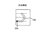
カートリッジホルダ20は、カートリッジホルダ20の主壁の内面から延びるピンなどの案内要素20aを有する。案内要素20aは、キャップ12の管状部材12aの外面に設けられた溝であるスロットリンク12bと係合する。スロットリンク12bは、キャップ12が使用者によって回されるとき、またキャップが本体から引き離されるときに案内要素20aがたどる経路を画成する。
The
図2Bは、スロットリンク12bによって画成された経路の二次元面への投影図である。スロットリンク12bは、この投影図では概ね鉤形をしている。図2Bに示された湾曲部分は、使用者がキャップ12を回したときに案内要素20aが取る経路を画成する。スロットリンクによって画成される湾曲経路は、軸方向に変化すると共に管状部材12aのまわりに円周方向に伸びる。したがって、キャップ12が本体11に対して回転するとスロットリンクによって画成された経路に沿って固定案内要素20aが動くことにより、キャップ12が軸方向に動くことになる。
FIG. 2B is a projection view of the path defined by the
スロットリンク12bの直線部分は、キャップ12が回転し、ニードルホルダ18が薬剤カートリッジ19に取り付けられた後に使用者がキャップ12を本体11から引っ張るときに案内要素20aが取る経路を画成する。スロットリンク12bは、キャップが十分に回されて薬剤カートリッジ19にニードルホルダ18が確実に取り付けられる前にキャップ12が取り外されることを防止する。
The straight portion of the
針17を保持するニードルホルダ18は、本体11およびカートリッジ19に対して軸方向に可動である。ニードルホルダは、概ねカップ形の部分18aと、針17が通過する通路とを有する。カップ形部分18aは、カートリッジ19のヘッド23と係合するように形づくられる。カップ形部分18aは、カートリッジ19にニードルホルダ18を取り付けた後にニードルホルダ18がカートリッジ19から外れることを防止するために、ヘッド23の上に留まる働きをするリップ18bを含む。針17の両端はとがっている。近位端は、針17が薬剤カートリッジ19のセプタム23aを貫通することが可能になるほど十分に鋭い。針17の遠位端は、針が患者の皮膚を貫通できるほど十分に鋭い。
The
図3Aは、使用者がキャップ12を回しているときのデバイス10を示す。案内要素20aは、スロットリンク12bによって画成された経路の湾曲部分に沿って動く。図3で、案内要素20aは、管状部材12aの近位端から最も遠いスロットリンク12bの部分にある。案内要素20aの位置は、本体11および薬剤カートリッジ19に対して軸方向に固定されており、またキャップ12は、本体11および薬剤カートリッジ19に対して軸方向に可動であるので、キャップ12が図2Aおよび図2Bに示された位置から回転すると、キャップ12が薬剤カートリッジ19に向かって軸方向に動くことになる。管状部材12aはニードルホルダ18に当接し、それによって、薬剤カートリッジ19に向かうニードルホルダの軸方向運動が生じる。
FIG. 3A shows the
図3Aに示されるように、針17は薬剤カートリッジ19のセプタム23aを穿孔し、それによって、薬剤が薬剤カートリッジ19から針17の遠位端まで流れるための経路が確立される。
As shown in FIG. 3A, the
軸方向に薬剤カートリッジに向かって動いた後に、ニードルホルダ18のカップ形部18aは、薬剤カートリッジ19のヘッド23に嵌まる。さらに、ニードルホルダのカップ形部18aのまわりに延びるリップ18bは、ニードルホルダ18を薬剤カートリッジ19に固定する役割も果たす。リップ18bは、カップ形部がヘッド23に嵌まるようにするためのテーパ付き案内縁部を有する。
After moving axially toward the drug cartridge, the cup-shaped
代替実施形態では、リップが設けられない。カップ形部18aの直径と、薬剤カートリッジ19のヘッド23の直径とは、ニードルホルダ18と薬剤カートリッジ19との間の緊密摩擦嵌めを確保するように配置される。
In the alternative embodiment, no lip is provided. The diameter of the cup-shaped
しかし、ニードルホルダ18が薬剤カートリッジ19に嵌まった後で、薬剤カートリッジ19から分離するニードルホルダの軸方向運動がリップまたは摩擦嵌めによって防止される。
However, after the
キャップ12が図3Aに示された位置を越えて回転すると、案内要素20aは、図3Bに示された案内要素20aの位置と軸方向に直線の経路の部分との間で、スロットリンク12bの湾曲部分に沿って案内される。スロットリンクの曲線の方向の故に、この段階でキャップが回転するとキャップ12は、ニードルホルダ18および薬剤カートリッジ19から軸方向に離れることになる。
As the
図4Aおよび図4Bは、キャップ12が取り外されるときのデバイス10を示す。案内要素20aは、スロットリンク12bの軸方向直線部分に達する。キャップ12は、スロットリンク12bが直線方向であるので、もはや回すことができない。使用者は、キャップ12を本体11から遠位方向に引っ張る。
4A and 4B show the
キャップ12が取り外された後、使用者は注射を開始することができる。デバイス10の遠位端は患者の注射部位に当てて保持され、デバイスが起動される。
After the
いくつかの実施形態では、図5に示されるように、スロットリンク12bは狭窄部分30を有することができ、この部分はスロットリンク12bの残りの部分よりも狭い。この狭窄部は、キャップ12の偶発的な回転を防止し、そのため針17は、時期尚早にカートリッジ19に挿入されない。
In some embodiments, as shown in FIG. 5, the
用語「薬物」または「薬剤」は、本明細書において同意語として使用され、1つまたはそれ以上の医薬品有効成分または薬学的に許容されるその塩もしくは溶媒和物と、場合により、薬学的に許容される担体とを含む医薬製剤を示す。医薬品有効成分(「API」)とは、最も広範な言い方で、ヒトまたは動物に生物学的影響を及ぼす化学構造のことである。薬理学では、薬物または薬剤が、疾患の処置、治療、予防、または診断に使用され、またはそれとは別に、身体的または精神的健康を向上させるために使用される。薬物または薬剤は、限られた継続期間、または慢性疾患では定期的に、使用される。 The term "drug" or "drug" is used herein as a consensus, with one or more active pharmaceutical ingredients or pharmaceutically acceptable salts or solvates thereof, and optionally pharmaceutically pharmaceutically. The pharmaceutical preparation containing an acceptable carrier is shown. A pharmaceutical active ingredient (“API”) is, in the broadest sense, a chemical structure that has a biological effect on humans or animals. In pharmacology, a drug or drug is used to treat, treat, prevent, or diagnose a disease, or separately, to improve physical or mental health. The drug or drug is used for a limited duration or regularly in chronic diseases.
以下に説明されるように、薬物または薬剤は、1つまたはそれ以上の疾患を処置するための、さまざまなタイプの製剤の少なくとも1つのAPI、またはその組み合わせを含むことができる。APIの例としては、分子量が500Da以下である低分子;ポリペプチド、ペプチド、およびタンパク質(たとえばホルモン、成長因子、抗体、抗体フラグメント、および酵素);炭水化物および多糖類;ならびに核酸、二本鎖または一本鎖DNA(裸およびcDNAを含む)、RNA、アンチセンスDNAおよびRNAなどのアンチセンス核酸、低分子干渉RNA(siRNA)、リボザイム、遺伝子、およびオリゴヌクレオチドが含まれ得る。核酸は、ベクター、プラスミド、またはリポソームなどの分子送達システムに組み込まれる。1つまたはそれ以上の薬物の混合物もまた企図される。 As described below, a drug or agent can include at least one API of different types of formulations, or a combination thereof, for treating one or more diseases. Examples of APIs are small molecules with a molecular weight of 500 Da or less; polypeptides, peptides, and proteins (eg, hormones, growth factors, antibodies, antibody fragments, and enzymes); carbohydrates and polysaccharides; and nucleic acids, double strands or It may include single-stranded DNA (including naked and cDNA), RNA, antisense nucleic acids such as antisense DNA and RNA, small interfering RNA (siRNA), ribozymes, genes, and oligonucleotides. Nucleic acids are integrated into molecular delivery systems such as vectors, plasmids, or liposomes. Mixtures of one or more drugs are also contemplated.
用語「薬物送達デバイス」は、薬物または薬剤をヒトまたは動物の体内に投薬するように構成されたあらゆるタイプのデバイスまたはシステムを包含するものである。それだけには限らないが、薬物送達デバイスは、注射デバイス(たとえばシリンジ、ペン型注射器、自動注射器、大容量デバイス、ポンプ、潅流システム、または眼内、皮下、筋肉内、もしくは血管内送達にあわせて構成された他のデバイス)、皮膚パッチ(たとえば、浸透圧性、化学的、マイクロニードル)、吸入器(たとえば鼻用または肺用)、埋め込み型デバイス(たとえば、薬物またはAPIコーティングされたステント、カプセル)、または胃腸管用の供給システムとすることができる。ここで説明される薬物は、たとえば24以上のゲージ数を有する、たとえば皮下針である針を含む注射デバイスでは特に有用であり得る。 The term "drug delivery device" includes any type of device or system configured to administer a drug or drug into the body of a human or animal. Drug delivery devices are configured for injection devices such as, but not limited to, syringes, pen-type injectors, automatic injectors, high volume devices, pumps, perfusion systems, or intraocular, subcutaneous, intramuscular, or intravascular delivery. Other devices), skin patches (eg osmotic, chemical, microneedles), inhalers (eg nasal or lung), implantable devices (eg drug or API coated stents, capsules), Alternatively, it can be a supply system for the gastrointestinal tract. The drugs described herein may be particularly useful in injection devices, including, for example, needles having a gauge number of 24 or greater, eg, a hypodermic needle.
薬物または薬剤は、薬物送達デバイスで使用するように適用された主要パッケージまたは「薬物容器」内に含まれる。薬物容器は、たとえば、カートリッジ、シリンジ、リザーバ、または1つもしくはそれ以上の薬物の保存(たとえば短期または長期保存)に適したチャンバを提供するように構成された他の固体もしくは可撓性の容器とすることができる。たとえば、場合によって、チャンバは、少なくとも1日(たとえば1日から少なくとも30日まで)の間薬物を収納するように設計される。場合によって、チャンバは、約1ヶ月から約2年の間薬物を保存するように設計される。保存は、室温(たとえば約20℃)または冷蔵温度(たとえば約−4℃から約4℃まで)で行うことができる。場合によって、薬物容器は、投与予定の医薬製剤の2つまたはそれ以上の成分(たとえばAPIおよび希釈剤、または2つの異なるタイプの薬物)を別々に、各チャンバに1つずつ保存するように構成された二重チャンバカートリッジとすることができ、またはこれを含むことができる。そのような場合、二重チャンバカートリッジの2つのチャンバは、ヒトまたは動物の体内に投薬する前、および/または投薬中に2つまたはそれ以上の成分間で混合することを可能にするように構成される。たとえば、2つのチャンバは、これらが(たとえば2つのチャンバ間の導管によって)互いに流体連通し、所望の場合、投薬の前にユーザによって2つの成分を混合することを可能にするように構成される。代替的に、またはこれに加えて、2つのチャンバは、成分がヒトまたは動物の体内に投薬されているときに混合することを可能にするように構成される。 The drug or drug is contained within the main package or "drug container" applied for use with the drug delivery device. The drug container is, for example, a cartridge, syringe, reservoir, or other solid or flexible container configured to provide a chamber suitable for storage of one or more drugs (eg, short-term or long-term storage). Can be. For example, in some cases, the chamber is designed to contain the drug for at least one day (eg, from 1 to at least 30 days). In some cases, the chamber is designed to store the drug for about 1 month to about 2 years. Storage can be performed at room temperature (eg, about 20 ° C.) or refrigerating temperature (eg, from about -4 ° C. to about 4 ° C.). In some cases, the drug container is configured to store two or more components of the pharmaceutical product to be administered (eg API and diluent, or two different types of drugs) separately, one in each chamber. Can be, or can include, a double chamber cartridge. In such cases, the two chambers of the dual chamber cartridge are configured to allow mixing between the two or more components before and / or during dosing into the human or animal body. Will be done. For example, the two chambers are configured to allow them to fluidize with each other (eg, by a conduit between the two chambers) and, if desired, allow the user to mix the two components prior to dosing. .. Alternatively, or in addition to this, the two chambers are configured to allow mixing when the ingredients are being administered into the human or animal body.
本明細書において説明される薬物送達デバイス内に含まれる薬物または薬剤は、数多くの異なるタイプの医学的障害の処置および/または予防に使用される。障害の例としては、たとえば、糖尿病、または糖尿病性網膜症などの糖尿病に伴う合併症、深部静脈血栓塞栓症または肺血栓塞栓症などの血栓塞栓症が含まれる。障害の別の例としては、急性冠症候群(ACS)、狭心症、心筋梗塞、がん、黄斑変性症、炎症、枯草熱、アテローム性動脈硬化症および/または関節リウマチがある。APIおよび薬物の例としては、たとえば、それだけには限らないが、ハンドブックのRote Liste 2014、主グループ12(抗糖尿病薬物)または主グループ86(腫瘍薬物)、およびMerck Index、第15版などに記載されているものがある。 The drugs or agents contained within the drug delivery devices described herein are used to treat and / or prevent a number of different types of medical disorders. Examples of disorders include, for example, diabetes or diabetic complications such as diabetic retinopathy, thromboembolism such as deep venous thromboembolism or pulmonary thromboembolism. Other examples of disorders include acute coronary syndrome (ACS), angina, myocardial infarction, cancer, macular degeneration, inflammation, hay fever, atherosclerosis and / or rheumatoid arthritis. Examples of APIs and drugs are described, for example, in, but not limited to, the Handbooks Rote Liste 2014, Main Group 12 (Anti-Diabetes Drugs) or Main Group 86 (Tumor Drugs), and Merck Index, 15th Edition. There is something that is.
1型もしくは2型の糖尿病、または1型もしくは2型の糖尿病に伴う合併症の処置および/または予防のためのAPIの例としては、インスリン、たとえばヒトインスリン、またはヒトインスリン類似体もしくは誘導体、グルカゴン様ペプチド(GLP−1)、GLP−1類似体もしくはGLP−1受容体アゴニスト、またはその類似体もしくは誘導体、ジペプチジルペプチダーゼ−4(DPP4)阻害剤、または薬学的に許容されるその塩もしくは溶媒和物、またはそれらの任意の混合物が含まれる。本明細書において使用される用語「類似体」および「誘導体」は、元の物質と構造的に十分に類似しており、それによって同様の機能または活性(たとえば治療効果性)を有することができる任意の物質を指す。特に、用語「類似体」は、天然のペプチドの構造、たとえばヒトのインスリンの構造から、天然のペプチド中に見出される少なくとも1つのアミノ酸残基を欠失させるおよび/もしくは交換することによって、ならびに/または少なくとも1つのアミノ酸残基を付加することによって式上で得られる分子構造を有するポリペプチドを指す。付加および/または交換されるアミノ酸残基は、コード可能なアミノ酸残基、または他の天然の残基もしくは完全に合成によるアミノ酸残基とすることができる。インスリン類似体は「インスリン受容体リガンド」とも呼ばれる。特に、用語「誘導体」は、1つまたはそれ以上の有機置換基(たとえば、脂肪酸)が1つまたはそれ以上のアミノ酸に結合している、天然のペプチドの構造、たとえばヒトのインスリンの構造から式上で得られる分子構造を有するポリペプチドを指す。場合により、天然のペプチド中に見出される1つまたはそれ以上のアミノ酸が、欠失され、かつ/もしくはコード不可能なアミノ酸を含む他のアミノ酸によって置換されていてもよく、または、コード不可能なアミノ酸を含むアミノ酸が、天然のペプチドに付加されていてもよい。 Examples of APIs for the treatment and / or prevention of type 1 or 2 diabetes or the complications associated with type 1 or 2 diabetes include insulin, such as human insulin, or human insulin analogs or derivatives, glucagon. Like peptide (GLP-1), GLP-1 analog or GLP-1 receptor agonist, or analog or derivative thereof, dipeptidyl peptidase-4 (DPP4) inhibitor, or pharmaceutically acceptable salt or solvent thereof. Includes Japanese or any mixture thereof. As used herein, the terms "analog" and "derivative" are structurally sufficiently similar to the original substance, thereby allowing them to have similar functions or activities (eg, therapeutic efficacy). Refers to any substance. In particular, the term "similar" is used by deleting and / or exchanging at least one amino acid residue found in a natural peptide from the structure of a natural peptide, eg, the structure of human insulin, and /. Alternatively, it refers to a polypeptide having a molecular structure obtained in the formula by adding at least one amino acid residue. The amino acid residues added and / or exchanged can be encodeable amino acid residues, or other naturally occurring or fully synthetic amino acid residues. Insulin analogs are also called "insulin receptor ligands". In particular, the term "derivative" is formulated from the structure of a natural peptide, eg, the structure of human insulin, in which one or more organic substituents (eg, fatty acids) are attached to one or more amino acids. Refers to the polypeptide having the molecular structure obtained above. In some cases, one or more amino acids found in natural peptides may be deleted and / or replaced by other amino acids, including non-encoding amino acids, or are non-encoding. Amino acids, including amino acids, may be added to the natural peptide.
インスリン類似体の例としては、Gly(A21),Arg(B31),Arg(B32)ヒトインスリン(インスリングラルギン);Lys(B3),Glu(B29)ヒトインスリン(インスリングルリジン);Lys(B28),Pro(B29)ヒトインスリン(インスリンリスプロ);Asp(B28)ヒトインスリン(インスリンアスパルト);B28位におけるプロリンがAsp、Lys、Leu、Val、またはAlaで置き換えられており、B29位において、LysがProで置換されているヒトインスリン;Ala(B26)ヒトインスリン;Des(B28−B30)ヒトインスリン;Des(B27)ヒトインスリンおよびDes(B30)ヒトインスリンがある。 Examples of insulin analogs include Gly (A21), Arg (B31), Arg (B32) human insulin (insulin glargine); Lys (B3), Glu (B29) human insulin (insulin glargine); Lys (B28). , Pro (B29) human insulin (insulin lispro); Asp (B28) human insulin (insulin aspart); proline at position B28 is replaced by Asp, Lys, Leu, Val, or Ala, and at position B29, Lys. There are human insulin in which is replaced with Pro; Ala (B26) human insulin; Des (B28-B30) human insulin; Des (B27) human insulin and Des (B30) human insulin.
インスリン誘導体の例としては、たとえば、B29−N−ミリストイル−des(B30)ヒトインスリン;Lys(B29)(N−テトラデカノイル)−des(B30)ヒトインスリン(インスリンデテミル、Levemir(登録商標))、B29−N−パルミトイル−des(B30)ヒトインスリン;B29−N−ミリストイルヒトインスリン;B29−N−パルミトイルヒトインスリン;B28−N−ミリストイルLysB28ProB29ヒトインスリン;B28−N−パルミトイル−LysB28ProB29ヒトインスリン;B30−N−ミリストイル−ThrB29LysB30ヒトインスリン;B30−N−パルミトイル−ThrB29LysB30ヒトインスリン;B29−N−(N−パルミトイル−γ−グルタミル)−des(B30)ヒトインスリン;B29−N−ω−カルボキシヘプタデカノイル−γ−L−グルタミル−des(B30)ヒトインスリン(インスリンデグルデク、Tresiba(登録商標))、B29−N−(N−リトコリル−γ−グルタミル)−des(B30)ヒトインスリン;B29−N−(ω−カルボキシヘプタデカノイル)−des(B30)ヒトインスリン、およびB29−N−(ω−カルボキシヘプタデカノイル)ヒトインスリンがある。 Examples of insulin derivatives include, for example, B29-N-myristoyl-des (B30) human insulin; Lys (B29) (N-tetradecanoyl) -des (B30) human insulin (insulin detemir, Revemir®). , B29-N-palmitoyle-des (B30) human insulin; B29-N-myristoyl human insulin; B29-N-palmitoyl human insulin; B28-N-myristoyl LysB28ProB29 human insulin; B28-N-palmitoyl-LysB28ProB29 human insulin; B30 -N-myristoyl-ThrB29LysB30 human insulin; B30-N-palmitoyle-ThrB29LysB30 human insulin; B29-N- (N-palmitoyle-γ-glutamyl) -des (B30) human insulin; B29-N-ω-carboxyheptadecanoyl -Γ-L-glutamyl-des (B30) human insulin (insulin detemirdec, Tresiba®), B29-N- (N-lithocholyl-γ-glutamyl) -des (B30) human insulin; B29-N -(Ω-carboxyheptadecanoyl) -des (B30) human insulin and B29-N- (ω-carboxyheptadecanoyl) human insulin.
GLP−1、GLP−1類似体およびGLP−1受容体アゴニストの例としては、たとえば、リキシセナチド(Lyxumia(登録商標)、エキセナチド(エキセンディン−4、Dyetta(登録商標)、Bydureon(登録商標)、アメリカドクトカゲの唾液腺によって産生される39アミノ酸ペプチド)、リラグルチド(Victoza(登録商標))、セマグルチド、タスポグルチド、アルビグルチド(Syncria(登録商標))、デュラグルチド(Trulicity(登録商標))、rエキセンディン−4、CJC−1134−PC、PB−1023、TTP−054、ラングレナチド/HM−11260C、CM−3、GLP−1エリゲン(Eligen)、ORMD−0901、NN−9924、NN−9926、NN−9927、ノデキセン(Nodexen)、ビアドール(Viador)−GLP−1、CVX−096、ZYOG−1、ZYD−1、GSK−2374697、DA−3091、MAR−701、MAR709、ZP−2929、ZP−3022、TT−401、BHM−034、MOD−6030、CAM−2036、DA−15864、ARI−2651、ARI−2255、エキセナチド−XTENおよびグルカゴン−Xtenがある。 Examples of GLP-1, GLP-1 analogs and GLP-1 receptor agonists include, for example, lixisenatide (Lyxumia®, exenatide (Exenatide-4, Dyetta®, Bydureon®), 39 amino acid peptide produced by the salivary gland of the American doctor lizard), liraglutide (Victoriza®), semaglutide, taspoglutide, albiglutide (Syncria®), duraglutide (Trucity®), r exenatide-4, CJC-1134-PC, PB-1023, TTP-054, Liraglutide / HM-11260C, CM-3, GLP-1 Eligen, ORMD-0901, NN-9924, NN-9926, NN-9927, Nodexen ( Nodexen), Viador-GLP-1, CVX-096, ZYOG-1, ZYD-1, GSK-2374697, DA-3091, MAR-701, MAR709, ZP-2929, ZP-3022, TT-401, There are BHM-034, MOD-6030, CAM-2036, DA-15864, ARI-2651, ARI-2255, exenatide-XTEN and glucagon-Xten.
オリゴヌクレオチドの例としては、たとえば:家族性高コレステロール血症の処置のためのコレステロール低下アンチセンス治療薬である、ミポメルセンナトリウム(Kynamro(登録商標))がある。 Examples of oligonucleotides are: for example: mipomersen sodium (Kynamro®), a cholesterol-lowering antisense therapeutic agent for the treatment of familial hypercholesterolemia.
DPP4阻害剤の例としては、ビルダグリプチン、シタグリプチン、デナグリプチン、サキサグリプチン、ベルベリンがある。 Examples of DPP4 inhibitors include vildagliptin, sitagliptin, denagliptin, saxagliptin and berberine.
ホルモンの例としては、ゴナドトロピン(フォリトロピン、ルトロピン、コリオンゴナドトロピン、メノトロピン)、ソマトロピン(ソマトロピン)、デスモプレシン、テルリプレシン、ゴナドレリン、トリプトレリン、ロイプロレリン、ブセレリン、ナファレリン、およびゴセレリンなどの、脳下垂体ホルモンまたは視床下部ホルモンまたは調節性活性ペプチドおよびそれらのアンタゴニストが含まれる。 Examples of hormones include gonadotropins (follitropin, lutropin, corion gonadotropin, menotropin), somatropin (somatropin), desmopressin, telllipresin, gonadorelin, triptolerin, leuprorelin, buserelin, nafarelin, and hypothalamic hormones or hypothalamus. Includes lower hormones or regulatory active peptides and their antagonists.
多糖類の例としては、グルコサミノグリカン、ヒアルロン酸、ヘパリン、低分子量ヘパリン、もしくは超低分子量ヘパリン、またはそれらの誘導体、または上述の多糖類の硫酸化形態、たとえば、ポリ硫酸化形態、および/または、薬学的に許容されるそれらの塩が含まれる。ポリ硫酸化低分子量ヘパリンの薬学的に許容される塩の例としては、エノキサパリンナトリウムがある。ヒアルロン酸誘導体の例としては、ハイランG−F20(Synvisc(登録商標))、ヒアルロン酸ナトリウムがある。 Examples of polysaccharides include glucosaminoglycans, hyaluronic acid, heparin, low molecular weight heparin, or ultra low molecular weight heparin, or derivatives thereof, or sulfated forms of the above-mentioned polysaccharides, such as polysulfated forms, and / Or those pharmaceutically acceptable salts are included. An example of a pharmaceutically acceptable salt of polysulfated low molecular weight heparin is enoxaparin sodium. Examples of hyaluronic acid derivatives include Hylan G-F20 (Synvisc®) and sodium hyaluronate.
本明細書において使用する用語「抗体」は、免疫グロブリン分子またはその抗原結合部分を指す。免疫グロブリン分子の抗原結合部分の例には、抗原を結合する能力を保持するF(ab)およびF(ab’)2フラグメントが含まれる。抗体は、ポリクローナル、モノクローナル、組換え型、キメラ型、非免疫型またはヒト化、完全ヒト型、非ヒト型(たとえばネズミ)、または一本鎖抗体とすることができる。いくつかの実施形態では、抗体はエフェクター機能を有し、補体を固定することができる。いくつかの実施形態では、抗体は、Fc受容体と結合する能力が低く、または結合することはできない。たとえば、抗体は、アイソタイプもしくはサブタイプ、抗体フラグメントまたは変異体とすることができ、これはFc受容体との結合を支持せず、たとえば、突然変異した、または欠失したFc受容体結合領域を有する。用語の抗体はまた、四価二重特異性タンデム免疫グロブリン(TBTI)および/または交差結合領域の配向性を有する二重可変領域抗体様結合タンパク質(CODV)に基づく抗体結合分子を含む。 As used herein, the term "antibody" refers to an immunoglobulin molecule or antigen-binding portion thereof. Examples of antigen-binding moieties of immunoglobulin molecules include F (ab) and F (ab') 2 fragments that retain their ability to bind antigen. Antibodies can be polyclonal, monoclonal, recombinant, chimeric, non-immune or humanized, fully human, non-human (eg, murine), or single chain antibodies. In some embodiments, the antibody has effector function and is capable of immobilizing complement. In some embodiments, the antibody has a low ability to bind or is unable to bind to the Fc receptor. For example, the antibody can be an isotype or subtype, antibody fragment or variant, which does not support binding to the Fc receptor, eg, a mutated or deleted Fc receptor binding region. Have. The term antibody also comprises a tetravalent bispecific tandem immunoglobulin (TBTI) and / or an antibody binding molecule based on a bivariable region antibody-like binding protein (CODV) with cross-binding region orientation.
用語「フラグメント」または「抗体フラグメント」は、全長抗体ポリペプチドを含まないが、抗原と結合することができる全長抗体ポリペプチドの少なくとも一部分を依然として含む、抗体ポリペプチド分子(たとえば、抗体重鎖および/または軽鎖ポリペプチド)由来のポリペプチドを指す。抗体フラグメントは、全長抗体ポリペプチドの切断された部分を含むことができるが、この用語はそのような切断されたフラグメントに限定されない。本発明に有用である抗体フラグメントは、たとえば、Fabフラグメント、F(ab’)2フラグメント、scFv(一本鎖Fv)フラグメント、直鎖抗体、単一特異性抗体フラグメント、または二重特異性、三重特異性、四重特異性および多重特異性抗体(たとえば、ダイアボディ、トリアボディ、テトラボディ)などの多重特異性抗体フラグメント、一価抗体フラグメント、または二価、三価、四価および多価抗体などの多価抗体フラグメント、ミニボディ、キレート組換え抗体、トリボディまたはバイボディ、イントラボディ、ナノボディ、小モジュラー免疫薬(SMIP)、結合ドメイン免疫グロブリン融合タンパク質、ラクダ化抗体、およびVHH含有抗体を含む。抗原結合抗体フラグメントのさらなる例が当技術分野で知られている。 The term "fragment" or "antibody fragment" does not include a full-length antibody polypeptide, but still contains at least a portion of a full-length antibody polypeptide capable of binding an antigen, such as an antibody polypeptide molecule (eg, antibody heavy chain and /). Or a polypeptide derived from a light chain polypeptide). The antibody fragment can include a cleaved portion of the full length antibody polypeptide, but the term is not limited to such cleaved fragments. Antibody fragments useful in the present invention include, for example, Fab fragment, F (ab') 2 fragment, scFv (single chain Fv) fragment, linear antibody, monospecific antibody fragment, or bispecific, triple. Multispecific antibody fragments, monovalent antibody fragments, or bivalent, trivalent, tetravalent and polyvalent antibodies such as specific, quadruspecific and multispecific antibodies (eg, diabody, triabodies, tetrabodies). Includes multivalent antibody fragments such as, minibody, chelate recombinant antibodies, tribody or bibody, intrabody, nanobody, small modular immunopharmaceuticals (SMIPs), binding domain immunoglobulin fusion proteins, camelized antibodies, and VHH-containing antibodies. Further examples of antigen-binding antibody fragments are known in the art.
用語「相補性決定領域」または「CDR」は、特異的抗原認識を仲介する役割を主に担う重鎖および軽鎖両方のポリペプチドの可変領域内の短いポリペプチド配列を指す。用語「フレームワーク領域」は、CDR配列ではなく、CDR配列の正しい位置決めを維持して抗原結合を可能にする役割を主に担う重鎖および軽鎖両方のポリペプチドの可変領域内のアミノ酸配列を指す。フレームワーク領域自体は、通常、当技術分野で知られているように、抗原結合に直接的に関与しないが、特定の抗体のフレームワーク領域内の特定の残基が、抗原結合に直接的に関与することができ、またはCDR内の1つまたはそれ以上のアミノ酸が抗原と相互作用する能力に影響を与えることができる。 The terms "complementarity determining regions" or "CDRs" refer to short polypeptide sequences within the variable regions of both heavy and light chain polypeptides that are primarily responsible for mediating specific antigen recognition. The term "framework regions" refers to amino acid sequences within the variable regions of both heavy and light chain polypeptides that are primarily responsible for maintaining the correct positioning of the CDR sequences and allowing antigen binding, rather than the CDR sequences. Point to. The framework region itself is usually not directly involved in antigen binding, as is known in the art, but certain residues within the framework region of a particular antibody are directly involved in antigen binding. It can be involved, or one or more amino acids in the CDR can affect the ability to interact with the antigen.
抗体の例としては、アンチPCSK−9mAb(たとえばアリロクマブ)、アンチIL−6mAb(たとえばサリルマブ)、およびアンチIL−4mAb(たとえばデュピルマブ)がある。 Examples of antibodies include anti-PCSK-9mAb (eg alirocumab), anti-IL-6mAb (eg sarilumab), and anti-IL-4mAb (eg dupilumab).
本明細書において説明される任意のAPIの薬学的に許容される塩もまた、薬物送達デバイスにおける薬物または薬剤の使用に企図される。薬学的に許容される塩は、たとえば酸付加塩および塩基性塩である。 Pharmaceutically acceptable salts of any API described herein are also contemplated for the use of a drug or drug in a drug delivery device. Pharmaceutically acceptable salts are, for example, acid addition salts and basic salts.
API、製剤、装置、方法、システムのさまざまな構成要素および本明細書に記載の実施形態の修正(追加および/または除去)を、このような修正、およびありとあらゆるその均等物を包含する本発明の全範囲および趣旨から逸脱せずに加えることができることは当業者に理解されよう。 Modifications (additions and / or removals) of the various components of APIs, formulations, devices, methods, systems and embodiments described herein, such modifications, and any equivalent thereof of the present invention. It will be appreciated by those skilled in the art that it can be added without departing from the full scope and purpose.
Claims (16)
薬剤カートリッジを受けるように配置された本体と;
該本体に対して軸方向に可動である、針を支持するニードルキャリアと;
該ニードルキャリアに取り外し可能に連結されている、デバイスの遠位端の回転可能キャップと、
案内要素およびスロットリンクを含む、本体とキャップとの間の解放可能配置とを含み、
ここで、スロットリンクは、キャップの回転運動中に案内要素が所定の経路を少なくとも一部軸方向にたどるように配置され、それによって、ニードルキャリアは、キャップが所定の点まで回転するにつれてデバイスの近位端に向かって軸方向に動き、
本体は、薬剤カートリッジホルダを含み、該薬剤カートリッジホルダは、キャップと係合するための案内要素を有し、該薬剤カートリッジホルダは、本体内に配置されている、前記薬剤注射デバイス。 A drug injection device:
With the body arranged to receive the drug cartridge;
With a needle carrier that supports the needle, which is axially movable with respect to the body;
A rotatable cap at the distal end of the device, detachably connected to the needle carrier,
Including releasable placement between the body and the cap, including guide elements and slot links,
Here, the slot link is arranged such that the guide element follows at least a predetermined path axially during the rotational movement of the cap, whereby the needle carrier is placed on the device as the cap rotates to a predetermined point. Axial movement towards the proximal end,
Body includes a medicine cartridge holder, the medicament cartridge holder, have a guide element for engaging the cap, the agent cartridge holder is disposed within the body, the drug injection device.
キャップを回し、それによって、案内要素およびスロットリンクを含む、本体とキャップとの間の解放可能配置が協働して、針を軸方向の近位方向に動かし、薬剤カートリッジの分離可能バリアを貫通することを含み、
ここで、本体は、薬剤カートリッジホルダを含み、薬剤カートリッジホルダは、キャップと係合するための案内要素を有し、該薬剤カートリッジホルダは、本体内に配置されている、前記方法。 A method of operating a drug injection device with a rotatable cap:
The cap is turned so that the releasable arrangement between the body and the cap, including the guide element and slot link, works together to move the needle axially proximally and through the separable barrier of the drug cartridge. Including doing
Here, the method, wherein the body comprises a drug cartridge holder, the drug cartridge holder has a guide element for engaging with a cap, and the drug cartridge holder is disposed within the body .
Applications Claiming Priority (3)
| Application Number | Priority Date | Filing Date | Title |
|---|---|---|---|
| EP15196709.8 | 2015-11-27 | ||
| EP15196709 | 2015-11-27 | ||
| PCT/EP2016/078274 WO2017089284A1 (en) | 2015-11-27 | 2016-11-21 | Medicament injection device |
Publications (3)
| Publication Number | Publication Date |
|---|---|
| JP2018535041A JP2018535041A (en) | 2018-11-29 |
| JP2018535041A5 JP2018535041A5 (en) | 2021-10-28 |
| JP6987056B2 true JP6987056B2 (en) | 2021-12-22 |
Family
ID=54705508
Family Applications (1)
| Application Number | Title | Priority Date | Filing Date |
|---|---|---|---|
| JP2018527134A Active JP6987056B2 (en) | 2015-11-27 | 2016-11-21 | Drug injection device |
Country Status (5)
| Country | Link |
|---|---|
| US (4) | US11213627B2 (en) |
| EP (1) | EP3380147A1 (en) |
| JP (1) | JP6987056B2 (en) |
| CN (1) | CN108601903B (en) |
| WO (1) | WO2017089284A1 (en) |
Families Citing this family (7)
| Publication number | Priority date | Publication date | Assignee | Title |
|---|---|---|---|---|
| JP6987056B2 (en) | 2015-11-27 | 2021-12-22 | サノフィ−アベンティス・ドイチュラント・ゲゼルシャフト・ミット・ベシュレンクテル・ハフツング | Drug injection device |
| EP3492126A1 (en) * | 2017-12-01 | 2019-06-05 | Sanofi | Injector device |
| EP3492125A1 (en) * | 2017-12-01 | 2019-06-05 | Sanofi | Injector device |
| EP3492123A1 (en) * | 2017-12-01 | 2019-06-05 | Sanofi | Injector device |
| DE202018107232U1 (en) * | 2018-12-18 | 2019-02-07 | FMW Technology Consulting GmbH | Device for the needle tube of a syringe |
| EP3976138A1 (en) | 2019-05-29 | 2022-04-06 | Sanofi | Assembly for a drug delivery device and drug delivery device |
| CN111450355B (en) * | 2020-03-23 | 2022-05-10 | 中国人民解放军海军军医大学 | Needle-prick-proof injector capable of pre-loading medicine |
Family Cites Families (16)
| Publication number | Priority date | Publication date | Assignee | Title |
|---|---|---|---|---|
| DE2315367A1 (en) * | 1973-03-28 | 1974-10-17 | Hoechst Ag | SINGLE USE INJECTION SYRINGE |
| US5250037A (en) | 1992-12-18 | 1993-10-05 | Becton, Dickinson And Company | Syringe having needle isolation features |
| IE970782A1 (en) | 1997-10-22 | 1999-05-05 | Elan Corp | An improved automatic syringe |
| AT410897B (en) | 2002-01-09 | 2003-08-25 | Pickhard Brigitte | INJECTION SYRINGE HEAD WITH ORIGINAL LOCK |
| WO2007131013A1 (en) | 2006-05-03 | 2007-11-15 | Antares Pharma, Inc. | Two-stage reconstituting injector |
| JP2009095392A (en) | 2007-10-13 | 2009-05-07 | Iwaki:Kk | Injection needle and injection syringe using it |
| US9327083B2 (en) * | 2010-04-07 | 2016-05-03 | Shl Group Ab | Medicament delivery device |
| WO2012072563A1 (en) * | 2010-11-29 | 2012-06-07 | Sanofi-Aventis Deutschland Gmbh | Medicated module with automatic reservoir engagement |
| JP5918483B2 (en) | 2011-06-21 | 2016-05-18 | 株式会社スズケン | Prefilled syringe |
| CH705692A2 (en) | 2011-11-03 | 2013-05-15 | Tecpharma Licensing Ag | Delivery device for mixing an active substance with a solution liquid. |
| EP2875838B1 (en) | 2012-07-19 | 2017-04-19 | Terumo Kabushiki Kaisha | Liquid-administering instrument |
| JP6046721B2 (en) | 2012-07-23 | 2016-12-21 | テルモ株式会社 | Liquid dosing device |
| AU2013346797B2 (en) | 2012-11-19 | 2016-07-28 | Shl Medical Ag | Injection needle assembly |
| EP3065800B1 (en) | 2013-10-18 | 2019-06-12 | Sanofi-Aventis Deutschland GmbH | Injection device |
| EP2923714A1 (en) | 2014-03-28 | 2015-09-30 | Sanofi-Aventis Deutschland GmbH | Autoinjector triggered by skin contact |
| JP6987056B2 (en) | 2015-11-27 | 2021-12-22 | サノフィ−アベンティス・ドイチュラント・ゲゼルシャフト・ミット・ベシュレンクテル・ハフツング | Drug injection device |
-
2016
- 2016-11-21 JP JP2018527134A patent/JP6987056B2/en active Active
- 2016-11-21 US US15/778,278 patent/US11213627B2/en active Active
- 2016-11-21 EP EP16798207.3A patent/EP3380147A1/en active Pending
- 2016-11-21 WO PCT/EP2016/078274 patent/WO2017089284A1/en active Application Filing
- 2016-11-21 CN CN201680080063.XA patent/CN108601903B/en active Active
-
2021
- 2021-12-30 US US17/566,155 patent/US11865307B2/en active Active
- 2021-12-30 US US17/566,188 patent/US11865308B2/en active Active
-
2023
- 2023-11-21 US US18/516,637 patent/US20240082495A1/en active Pending
Also Published As
| Publication number | Publication date |
|---|---|
| CN108601903A (en) | 2018-09-28 |
| US11865307B2 (en) | 2024-01-09 |
| EP3380147A1 (en) | 2018-10-03 |
| WO2017089284A1 (en) | 2017-06-01 |
| US11865308B2 (en) | 2024-01-09 |
| US11213627B2 (en) | 2022-01-04 |
| US20220118187A1 (en) | 2022-04-21 |
| US20220118186A1 (en) | 2022-04-21 |
| US20240082495A1 (en) | 2024-03-14 |
| CN108601903B (en) | 2021-10-08 |
| US20180344934A1 (en) | 2018-12-06 |
| JP2018535041A (en) | 2018-11-29 |
Similar Documents
| Publication | Publication Date | Title |
|---|---|---|
| JP6993332B2 (en) | Drug injection device | |
| JP6987056B2 (en) | Drug injection device | |
| JP6916179B2 (en) | Drug injection device | |
| JP6964584B2 (en) | Drug injection device with spring-supported protective needle cap | |
| JP6952032B2 (en) | Drug delivery device | |
| JP6924189B2 (en) | Drug injection device | |
| JP7037481B2 (en) | Drug delivery device | |
| JP6986544B2 (en) | Needle assembly | |
| US20220001107A1 (en) | Medicament injection device | |
| JP6884146B2 (en) | Drug injection device | |
| JP7038051B2 (en) | Drug injection device with pivotal needle holder | |
| JP6902541B2 (en) | Cap removal system | |
| JP7026615B2 (en) | Injection device with an axially moving needle holder | |
| JP6944450B2 (en) | Drug injection device | |
| JP7030693B2 (en) | Drug injection device | |
| JP6987142B2 (en) | Drug injection device | |
| JP7026614B2 (en) | Drug injection device | |
| JP6937754B2 (en) | Drug delivery device |
Legal Events
| Date | Code | Title | Description |
|---|---|---|---|
| A621 | Written request for application examination |
Free format text: JAPANESE INTERMEDIATE CODE: A621 Effective date: 20191107 |
|
| A977 | Report on retrieval |
Free format text: JAPANESE INTERMEDIATE CODE: A971007 Effective date: 20201113 |
|
| A131 | Notification of reasons for refusal |
Free format text: JAPANESE INTERMEDIATE CODE: A131 Effective date: 20201124 |
|
| A521 | Request for written amendment filed |
Free format text: JAPANESE INTERMEDIATE CODE: A523 Effective date: 20210224 |
|
| A131 | Notification of reasons for refusal |
Free format text: JAPANESE INTERMEDIATE CODE: A131 Effective date: 20210615 |
|
| A524 | Written submission of copy of amendment under article 19 pct |
Free format text: JAPANESE INTERMEDIATE CODE: A524 Effective date: 20210915 |
|
| TRDD | Decision of grant or rejection written | ||
| A01 | Written decision to grant a patent or to grant a registration (utility model) |
Free format text: JAPANESE INTERMEDIATE CODE: A01 Effective date: 20211102 |
|
| A61 | First payment of annual fees (during grant procedure) |
Free format text: JAPANESE INTERMEDIATE CODE: A61 Effective date: 20211130 |
|
| R150 | Certificate of patent or registration of utility model |
Ref document number: 6987056 Country of ref document: JP Free format text: JAPANESE INTERMEDIATE CODE: R150 |