CN108601903B - Medicament injection device - Google Patents
Medicament injection device Download PDFInfo
- Publication number
- CN108601903B CN108601903B CN201680080063.XA CN201680080063A CN108601903B CN 108601903 B CN108601903 B CN 108601903B CN 201680080063 A CN201680080063 A CN 201680080063A CN 108601903 B CN108601903 B CN 108601903B
- Authority
- CN
- China
- Prior art keywords
- cap
- needle
- drug cartridge
- drug
- slotted link
- Prior art date
- Legal status (The legal status is an assumption and is not a legal conclusion. Google has not performed a legal analysis and makes no representation as to the accuracy of the status listed.)
- Active
Links
Images


Classifications
-
- A—HUMAN NECESSITIES
- A61—MEDICAL OR VETERINARY SCIENCE; HYGIENE
- A61M—DEVICES FOR INTRODUCING MEDIA INTO, OR ONTO, THE BODY; DEVICES FOR TRANSDUCING BODY MEDIA OR FOR TAKING MEDIA FROM THE BODY; DEVICES FOR PRODUCING OR ENDING SLEEP OR STUPOR
- A61M5/00—Devices for bringing media into the body in a subcutaneous, intra-vascular or intramuscular way; Accessories therefor, e.g. filling or cleaning devices, arm-rests
- A61M5/178—Syringes
- A61M5/24—Ampoule syringes, i.e. syringes with needle for use in combination with replaceable ampoules or carpules, e.g. automatic
- A61M5/2455—Ampoule syringes, i.e. syringes with needle for use in combination with replaceable ampoules or carpules, e.g. automatic with sealing means to be broken or opened
- A61M5/2466—Ampoule syringes, i.e. syringes with needle for use in combination with replaceable ampoules or carpules, e.g. automatic with sealing means to be broken or opened by piercing without internal pressure increase
-
- A—HUMAN NECESSITIES
- A61—MEDICAL OR VETERINARY SCIENCE; HYGIENE
- A61M—DEVICES FOR INTRODUCING MEDIA INTO, OR ONTO, THE BODY; DEVICES FOR TRANSDUCING BODY MEDIA OR FOR TAKING MEDIA FROM THE BODY; DEVICES FOR PRODUCING OR ENDING SLEEP OR STUPOR
- A61M5/00—Devices for bringing media into the body in a subcutaneous, intra-vascular or intramuscular way; Accessories therefor, e.g. filling or cleaning devices, arm-rests
- A61M5/178—Syringes
- A61M5/31—Details
- A61M5/32—Needles; Details of needles pertaining to their connection with syringe or hub; Accessories for bringing the needle into, or holding the needle on, the body; Devices for protection of needles
- A61M5/3202—Devices for protection of the needle before use, e.g. caps
-
- A—HUMAN NECESSITIES
- A61—MEDICAL OR VETERINARY SCIENCE; HYGIENE
- A61M—DEVICES FOR INTRODUCING MEDIA INTO, OR ONTO, THE BODY; DEVICES FOR TRANSDUCING BODY MEDIA OR FOR TAKING MEDIA FROM THE BODY; DEVICES FOR PRODUCING OR ENDING SLEEP OR STUPOR
- A61M5/00—Devices for bringing media into the body in a subcutaneous, intra-vascular or intramuscular way; Accessories therefor, e.g. filling or cleaning devices, arm-rests
- A61M5/178—Syringes
- A61M5/24—Ampoule syringes, i.e. syringes with needle for use in combination with replaceable ampoules or carpules, e.g. automatic
- A61M5/2455—Ampoule syringes, i.e. syringes with needle for use in combination with replaceable ampoules or carpules, e.g. automatic with sealing means to be broken or opened
- A61M5/2466—Ampoule syringes, i.e. syringes with needle for use in combination with replaceable ampoules or carpules, e.g. automatic with sealing means to be broken or opened by piercing without internal pressure increase
- A61M2005/2474—Ampoule syringes, i.e. syringes with needle for use in combination with replaceable ampoules or carpules, e.g. automatic with sealing means to be broken or opened by piercing without internal pressure increase with movable piercing means, e.g. ampoule remains fixed or steady
Abstract
A medication injection device comprising: a body arranged to receive a drug cartridge; a hub carrying a needle, wherein the hub is axially movable relative to the body; and a rotatable cap at a distal end of the device, wherein the cap is removably coupled to the needle hub, a releasable arrangement between the body and the cap, the releasable arrangement comprising a guide element and a slotted link, wherein the slotted link is arranged to cause the guide element to at least partially follow a predetermined path in an axial direction during rotational movement of the cap, thereby moving the needle hub axially towards a proximal end of the device as the cap rotates up to a predetermined point, wherein the body comprises a drug cartridge holder comprising the guide element suspended from the drug cartridge holder for engagement with the cap.
Description
Technical Field
The present invention relates to a medicament injection device.
Background
The medicament injection device may take various forms. One form uses a syringe cartridge in which the medicament is stored in a hollow cylinder, typically formed of glass. The medicament is sealed from the environment by a plunger movable within the barrel and a needle fluidly connected to the distal end of the syringe barrel. The needle must remain capped to maintain the drug in a sterile condition.
Another form of injection device uses a cartridge instead of a syringe, the cartridge having a distal seal instead of the needle of the syringe. Typically, the patient connects the double ended needle to the cartridge prior to injection, whereby the proximal tip of the double ended needle pierces the seal of the cartridge.
Although cartridges may provide operational and storage advantages over syringes, they are not without disadvantages. For example, attaching the needle to the cartridge requires an additional step. This step can be problematic for patients with limited dexterity, poor coordination, or a degree of sensory loss in their hands. Even with such disadvantages, in some instances it is desirable to provide an injection device in which the needle remains separated from the medicament until such time as the patient wishes to initiate an injection.
Disclosure of Invention
A first embodiment provides a medicament injection apparatus comprising: a body arranged to receive a drug cartridge; a hub carrying a needle, wherein the hub is axially movable relative to the body; and a rotatable cap at a distal end of the device, wherein the cap is removably coupled to a needle hub, a releasable arrangement between the body and the cap, the releasable arrangement comprising a guide element and a slotted link, wherein the slotted link is arranged to cause the guide element to at least partially follow a predetermined path in an axial direction during rotational movement of the cap, thereby moving the needle hub axially towards a proximal end of the device as the cap rotates up to a predetermined point, wherein the body comprises a drug cartridge holder comprising the guide element suspended from the drug cartridge holder for engagement with the cap.
The cap may comprise a tubular element with the slotted link arranged on an outer surface of the tubular needle shield element for receiving the guide element.
The tubular element may comprise a needle shield.
The slotted link may be configured to move the cap in an axial direction along a distal axis when the cap is rotated beyond the predetermined point.
The slotted link may include a narrower portion than the remainder of the slotted link.
The slotted link may include an axial straight portion.
The needle holder may be arranged to become fixed to the drug cartridge after its axial movement in the proximal direction.
The needle holder may comprise a lip arranged to cooperate with a head of the drug cartridge.
The needle holder may be dimensioned to form a friction fit with the head of the drug cartridge.
The drug cartridge holder may comprise a drug cartridge having a penetrable septum at a distal end thereof, and axial movement of the needle hub towards the proximal end may cause the needle to puncture the septum of the drug cartridge.
The medicament cartridge may contain a medicament.
The device may be an auto-injector.
A second embodiment provides a method of operating a medicament injection device having a rotatable cap, the method comprising: rotating the cap thereby causing a releasable arrangement between the body and the cap comprising a guide element and a slotted link to cooperate to axially move the needle in a proximal direction and pierce a detachable septum of a drug cartridge.
Further rotation of the cap may cause the cap to move in a distal direction in an axial direction.
Drawings
Exemplary embodiments of the invention are described with reference to the accompanying drawings, in which:
FIGS. 1A and 1B are side views of an autoinjector device according to an embodiment of the present invention;
FIG. 2A is a side cross-sectional schematic view of a device having a cap according to a first embodiment, prior to cap rotation;
FIG. 2B is a diagram of the engagement of a guide element with a slotted link in the device shown in FIG. 2A;
FIG. 3A is a side cross-sectional schematic view of the device of the first embodiment as the cap is rotated;
FIG. 3B is a diagram of the engagement of a guide element with a slotted link in the device shown in FIG. 3A;
FIG. 4A is a side cross-sectional schematic view of the device of the first embodiment when the cap is being removed;
FIG. 4B is a diagram of the engagement of a guide element with a slotted link in the device shown in FIG. 4A; and
figure 5 shows a narrowing of the slotted link.
Detailed Description
Embodiments provide a mechanism for inserting an injection needle of an injection device, such as an auto-injector or a syringe, into a medicament cartridge containing a medicament to be injected. Providing such a mechanism allows the drug cartridge to be sealed until the user wishes to initiate an injection. Providing an automatic mechanism for inserting the needle into the drug cartridge also reduces the amount of user handling of the needle prior to injection. Indeed, in embodiments of the present invention, the user does not need to touch the needle during the steps of inserting the needle into the drug cartridge and then actuating the drug injection.
Embodiments provide a mechanism that causes a needle holder holding a needle to automatically connect to a drug cartridge in response to rotation of a cap of the device.
A drug delivery device as described herein may be configured to inject a drug into a patient. For example, delivery may be subcutaneous, intramuscular, or intravenous. Such devices may be operated by a patient or caregiver (e.g., a nurse or physician) and may include various types of safety syringes, pen-type injectors, or auto-injectors. The device may include a cartridge-based system that requires piercing of a sealed ampoule prior to use. The volume of drug delivered with these various devices may range from about 0.5ml to about 2 ml. Another device may include a large volume device ("LVD") or a patch pump configured to be attached to the skin of a patient over a period of time (e.g., about 5, 15, 30, 60, or 120 minutes) to deliver a "large" volume of drug (typically about 2ml to about 10 ml).
The presently described devices may also be customized to operate within the required specifications in conjunction with a particular drug. For example, the device may be customized to inject the drug over a period of time (e.g., about 3 seconds to about 20 seconds for an auto injector, about 10 minutes to about 60 minutes for an LVD). Other specifications may include low or minimal discomfort, or certain conditions related to human factors, shelf life, expiration date, biocompatibility, environmental considerations, and the like. These variations can occur due to various factors, such as drugs having viscosities in the range of about 3cP to about 50 cP. Accordingly, drug delivery devices will typically include hollow needles ranging in size from about 25 Gauge to about 31 Gauge (Gauge). Common sizes are 27 and 29.
The delivery devices described herein may also include one or more automated functions. For example, one or more of needle insertion, drug injection, and needle retraction may be automated. The energy for one or more automated steps may be provided by one or more energy sources. The energy source may include, for example, mechanical, pneumatic, chemical, or electrical energy. For example, the mechanical energy source may include a spring, a lever, an elastomer, or other mechanical mechanism that stores or releases energy. One or more energy sources may be combined into a single device. The device may further include gears, valves, or other mechanisms that convert energy into movement of one or more components of the device.
One or more automated functions of the autoinjector may each be activated via an activation mechanism. Such activation mechanisms may include one or more of a button, lever, needle sleeve, or other activation component. The activation of the automation function may be a single step or a multi-step process. That is, a user may need to activate one or more activation components to create an automated function. For example, in a single step process, a user may press the needle hub against their body to cause injection of the medicament. Other devices may require multi-step activation of automated functions. For example, the user may need to depress the button and retract the needle shield to cause an injection.
In addition, activation of one automation function may activate one or more subsequent automation functions, thereby forming an activation sequence. For example, activation of the first automated function may activate at least two of needle insertion, drug injection, and needle retraction. Some devices may also require a particular sequence of steps to cause one or more automated functions. Other devices may operate through a series of independent steps.
Some delivery devices may include one or more functions of a safety syringe, pen injector, or auto-injector. For example, the delivery device may include a mechanical energy source (as is commonly found in auto-injectors) and a dose setting mechanism (as is commonly found in pen injectors) configured to automatically inject the medicament.
An exemplary drug delivery device 10 is shown in fig. 1A and 1B, according to some embodiments of the present disclosure. The device 10 as described above is configured to inject a drug into a patient. The device 10 includes a body 11, the body 11 typically housing a reservoir (e.g., a syringe) containing the drug to be injected and the components necessary to facilitate one or more steps of the delivery process. The device 10 may further include a cap assembly 12, the cap assembly 12 being removably mountable to the body 11. Typically, the user must first remove the cap 12 from the body 11 before the device 10 can be operated.
As shown, the body 11 is generally cylindrical and has a diameter that is substantially constant along the longitudinal axis X. The main body 11 has a distal region 120 and a proximal region 121. The term "distal" refers to a location closer to the injection site, while the term "proximal" refers to a location further from the injection site.
The device 10 may also include a needle sleeve 24, the needle sleeve 24 being coupled to the body 11 to allow the sleeve 24 to move relative to the body 11. For example, the sleeve 24 may be movable along a longitudinal direction parallel to the longitudinal axis X. In particular, movement of the sleeve 24 in the proximal direction may allow the needle 17 to extend from the distal region 120 of the body 11.
Insertion of the needle 17 may occur via a number of mechanisms. For example, the needle 17 may be fixedly positioned relative to the body 11 and initially within the extended needle sleeve 24. Proximal movement of the sleeve 24 caused by placing the distal end of the sleeve 24 against the patient's body and moving the body 11 in a distal direction will expose the needle 17. Such relative movement allows the distal end of the needle 17 to extend into the patient's body. This insertion is referred to as "manual" insertion because the needle 17 is inserted manually via manual movement of the body 11 relative to the sleeve 24 by the patient.
Another form of insertion is "automated" whereby the needle 17 is moved relative to the body 11. The insertion can be triggered by movement of the sleeve 24 or by another form of activation (e.g., button 122). As shown in fig. 1A and 1B, the button 122 may be located at the proximal end of the body 11. However, in other embodiments, the button 122 can be located on the side of the body 11.
Other manual or automatic features may include drug injection or needle retraction, or both. Injection is the process of the bung or piston 123 moving from a proximal position within the syringe barrel (not shown) to a more distal position within the syringe barrel to force medicament from the syringe barrel through the needle 17. In some embodiments, the drive spring (not shown) is under compression prior to activation of the device 10. A proximal end of the drive spring may be secured within the proximal region 121 of the body 11, and a distal end of the drive spring may be configured to apply a compressive force to a proximal surface of the piston 123. After activation, at least a portion of the energy stored in the drive spring may be applied to the proximal surface of piston 123. This pressing force may act on piston 123 causing it to move in the distal direction. This distal movement acts to compress the liquid drug in the syringe barrel, forcing it out of the needle 17.
After injection, the needle 17 may be retracted into the sleeve 24 or body 11. Retraction may occur when sleeve 24 is moved in a distal direction as the user removes device 10 from the patient's body. This may occur while the needle 17 remains fixedly positioned relative to the body 11. Once the distal end of the sleeve 24 has moved past the distal end of the needle 17 and the needle 17 is covered, the sleeve 24 may be locked. This locking may include any proximal movement of the locking sleeve 24 relative to the body 11.
Another form of needle retraction may occur as the needle 17 is moved relative to the body 11. This movement may occur if a syringe within the main body 11 is moved in a proximal direction relative to the main body 11. This proximal movement can be achieved by using a retraction spring (not shown) located in the distal region 120. The compressed retraction spring, when activated, can provide sufficient force to the syringe barrel to move the syringe barrel in a proximal direction. After sufficient retraction, any relative movement between the needle 17 and the body 11 can be locked with a locking mechanism. In addition, the button 122 or other components of the device 10 may be locked as desired.
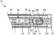
Fig. 2A shows a side cross-section of an autoinjector device 10 according to a first embodiment of the present invention. The device 10 comprises a generally cylindrical body 11 and a generally cylindrical cap 12.
The device 10 further comprises a tubular needle sleeve 24, the needle sleeve 24 being mounted within the main body 11 and arranged to slide in an axial direction relative to the main body 11. The needle sleeve 24 is a protective sleeve that prevents undesired exposure of the needle 17. The needle sleeve 24 has a body-like shape and is hollow and substantially cylindrical.
The material of the needle shield may be an elastomer like known needle shields for syringes of auto-injectors. The needle shield may also be made of a thermoplastic elastomer (TPE), which may be 2K injection molded into cap 12.
The needle shield is fixed to the cap in movement in the axial direction so that the needle shield 12c is also removed when the cap is removed.
The cap 12 is mounted on the needle cannula 24. The cap 12 is axially movable relative to the body 11.
The device 10 comprises a cartridge 19 held in place by a cartridge holder 20. The cartridge holder 20 and the cartridge 19 are connected and fixed with respect to the body 11 of the device 10. The cartridge 19 may be provided to the user independently of the device 10. The user may insert the cartridge 19 into the device 10.
The device 10 comprises a needle 17, the needle 17 being held towards its proximal end by a needle holder 18. The distal end of the needle 17 is covered by the tubular member 12a of the cap 12. The needle holder 18 holding the needle 17 is axially movable relative to the body 11 and the cartridge 19.
The cartridge 19 has a cartridge body 21, a neck 22 and a head 23. The head 23 is wider than the neck 22, forming a flanged end. The neck 22 and head 23 contain a channel that allows the passage of the drug and receives the needle 17 once the needle is inserted. The head 23 is provided with a penetrable septum, such as septum 23a, to close the channel and seal the contents of the drug cartridge 19. The cartridge body 21, neck 22 and head 23 may be substantially cylindrical. However, alternative shapes may be employed. The cup-shaped portion 18a is shaped to engage with the head 23 of the cartridge 19.
The cartridge holder 20 is generally tubular and coaxial with respect to the body 11. The main wall of cartridge holder 20 extends around the body 21 of cartridge 19 and towards the distal end of device 10 such that it surrounds the head 23 of cartridge 19, needle holder 18 and the proximal part of tubular member 12a of cap 12. The diameter of cartridge holder 20 is larger than the diameter of cartridge 19 and the diameter of needle holder 18. The cartridge holder 20 has ribs 25, the ribs 25 extending inwardly from the main wall to support the cartridge 19 along the length of the cartridge 19. Alternatively, the diameter of the cartridge holder 20 is approximately equal to the diameter of the cartridge 19, thereby providing a friction fit between the cartridge 19 and the cartridge holder 20, thereby eliminating the need for ribs. The diameter of the cartridge holder 20 is substantially equal to the diameter of the tubular member 12A so that a friction fit is achieved when the cap 12 is attached to the rest of the device 10, as shown in fig. 2A.
The cartridge holder 20 has a guiding element 20a, such as a pin extending from the inner surface of the main wall of the cartridge holder 20. The guide element 20a engages with a slotted link 12b, the slotted link 12b being a groove provided in the outer surface of the tubular member 12a of the cap 12. The slotted link 12b defines a path that is followed by the guide element 20a when the user rotates the cap 12 and when the cap is pulled away from the body.
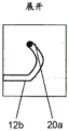
Fig. 2B is a projection of the path defined by the slotted link 12B onto a two-dimensional surface. The slotted link 12b is generally hook-shaped in this projection. The curved portion shown in fig. 2B defines the path taken by the guide element 20a when the user rotates the cap 12. The curved path defined by the slotted link varies axially and extends circumferentially around the tubular member 12 a. Thus, when the cap 12 is rotated relative to the body 11, movement of the fixed guide element 20a along the path defined by the slotted link results in axial movement of the cap 12.
The straight portion of the slotted link 12b defines the path taken by the guide element 20a when the user pulls the cap 12 up from the body 11 after the cap 12 is rotated and the needle holder 18 is attached to the drug cartridge 19. The slotted link 12b prevents separation of the cap 12 before the cap has been rotated sufficiently to ensure attachment of the needle holder 18 to the drug cartridge 19.
A needle holder 18 holding a needle 17 is axially movable relative to the body 11 and the cartridge 19. The needle holder has a generally cup-shaped portion 18a and a passage through which the needle 17 passes. The cup-shaped portion 18a is shaped to engage with the head 23 of the cartridge 19. The cup portion 18a includes a lip 18b, the lip 18b to clip onto the head 23 to prevent the needle holder 18 from separating from the cartridge 19 after the needle holder 18 is attached to the cartridge 19. The ends of the needle 17 are sharp. The proximal end is sufficiently sharp to enable the needle 17 to penetrate the septum 23a of the drug cartridge 19. The distal end of the needle 17 is sufficiently sharp to allow the needle to penetrate the patient's skin.
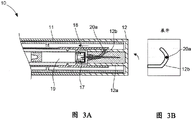
Fig. 3A shows the device 10 when the user rotates the cap 12. The guide element 20a moves along a curved portion of the path defined by the slotted link 12 b. In fig. 3, the guide element 20a is located in the portion of the slotted link 12b that is furthest from the proximal end of the tubular member 12 a. Since the position of the guiding element 20a is axially fixed with respect to the body 11 and the drug cartridge 19 and the cap 12 are axially movable with respect to the body 11 and the drug cartridge 19, rotation of the cap 12 from the position shown in fig. 2A and 2B results in an axial movement of the cap 12 towards the drug cartridge 19. The tubular member 12a abuts the needle holder 18 thereby causing axial movement of the needle holder towards the drug cartridge 19.
As shown in fig. 3A, the needle 17 pierces the septum 23A of the drug cartridge 19, thereby establishing a passage for the drug to flow from the drug cartridge 19 to the distal end of the needle 17.
After axial movement towards the medicament cartridge, the cup-shaped portion 18a of the needle holder 18 fits over the head portion 23 of the medicament cartridge 19. Furthermore, the lip 18b extending around the cup-shaped portion 18a of the needle holder also serves to secure the needle holder 18 to the drug cartridge 19. The lip 18b has a tapered leading edge to allow the cup to fit over the head 23.
In an alternative embodiment, no lip is provided. The diameter of the cup-shaped portion 18a and the diameter of the head 23 of the medicament cartridge 19 may be arranged to ensure a tight friction fit between the needle holder 18 and the medicament cartridge 19.
However, once needle holder 18 is assembled to drug cartridge 19, axial movement of the needle holder away from drug cartridge 19 and separation from drug cartridge 19 is prevented by a lip or friction fit.
When the cap 12 is rotated beyond the position shown in fig. 3A, the guide element 20a is guided along the curved portion of the slotted link 12B between the guide element 20a position shown in fig. 3B and the axially straight portion of the path. Rotation of the cap at this stage causes the cap 12 to move axially away from the needle holder 18 and the medicament cartridge 19 due to the direction of the bending of the slotted link.
Fig. 4A and 4B show the device 10 with the cap 12 removed. The guide element 20a reaches the axial straight portion of the slotted link 12 b. The cap 12 can no longer rotate due to the axial guidance of the slotted link 12 b. The user pulls the cap 12 away from the body 11 in the distal direction.
Once the cap 12 is removed, the user may begin the injection. The distal end of the device 10 is held against the injection site of the patient and the device is actuated.
In some embodiments, as shown in fig. 5, the slotted link 12b may have a narrow portion 30, the narrow portion 30 being narrower than the remainder of the slotted link 12 b. This helps prevent accidental rotation of cap 12 so that needle 17 is not inserted prematurely into cartridge 19.
The terms "drug" or "agent" are used synonymously herein and describe a pharmaceutical formulation containing one or more active pharmaceutical ingredients or a pharmaceutically acceptable salt or solvate thereof and optionally a pharmaceutically acceptable carrier. In its broadest sense, an active pharmaceutical ingredient ("API") is a chemical structure that has a biological effect on humans or animals. In pharmacology, drugs or medicaments are used in the treatment, cure, prevention or diagnosis of diseases or to otherwise enhance physical or mental health. Drugs or medicaments may be used for a limited duration of time, or periodically for chronic diseases.
As described below, the drug or medicament may include at least one API, or a combination thereof, in various forms of formulations for the treatment of one or more diseases. Examples of APIs may include small molecules having a molecular weight below 500 Da; a polypeptide; peptides and proteins (e.g., hormones, growth factors, antibodies, antibody fragments, and enzymes); sugars and polysaccharides; and nucleic acids, double-or single-stranded DNA (including naked and cDNA), RNA, antisense nucleic acids such as antisense DNA and RNA, small interfering RNA (siRNA), ribozymes, genes, and oligonucleotides. The nucleic acid may be incorporated into a molecular delivery system such as a vector, plasmid or liposome. Mixtures of one or more drugs are also contemplated.
The term "drug delivery device" shall cover any type of device or system configured to dispense a drug into the body of a human or animal. Without limitation, the drug delivery device may be an injection device (e.g., syringe, pen-type injector, auto-injector, bulk device, pump, infusion system, or other device configured for intraocular, subcutaneous, intramuscular, or intravascular delivery), a dermal patch (e.g., osmotic, chemical, microneedle), an inhaler (e.g., for the nose or lung), an implantable device (e.g., drug or API-coated stent, capsule), or a delivery system for the gastrointestinal tract. The medicaments described herein may be particularly useful with injection devices that include a needle (e.g., a hypodermic needle having a gauge number of 24 or higher).
The medicament or medicament may be contained within a primary package or "drug container" suitable for use with the drug delivery device. The drug container may be, for example, a cartridge, syringe, reservoir, or other fixed or flexible container configured to provide a suitable chamber for storing (e.g., short-term or long-term storage) one or more drugs. For example, in some cases, the chamber may be designed to store the drug for at least one day (e.g., 1 day to at least 30 days). In some cases, the chamber may be designed to store the drug for about 1 month to about 2 years. Storage may be at room temperature (e.g., about 20 ℃) or at freezing temperatures (e.g., about-4 ℃ to about 4 ℃). In certain instances, the drug container may be or include a dual-chamber cartridge configured to separately store two or more components (e.g., API and diluent, or two different drugs) of a drug formulation to be administered, one component for each chamber. In such cases, the two chambers of the dual-chamber cartridge may be configured to allow mixing between two or more components of a drug or medicament prior to and/or during dispensing into the human or animal body. For example, the two chambers may be configured such that they are in fluid communication with each other (e.g., via a conduit between the two chambers) and allow the two components to be mixed when desired by a user prior to dispensing. Alternatively or additionally, the two chambers may be configured to allow mixing while the ingredients are being dispensed into the human or animal body.
The drugs or agents contained in a drug delivery device as described herein may be used to treat and/or prevent many different types of medical conditions. Examples of disorders include, for example, diabetes or complications associated with diabetes, such as diabetic retinopathy, thromboembolic disorders such as deep vein or pulmonary thromboembolism. Other examples of disorders are Acute Coronary Syndrome (ACS), angina pectoris, myocardial infarction, cancer, macular degeneration, inflammation, hay fever, atherosclerosis and/or rheumatoid arthritis. Examples of APIs and drugs are those described in manuals such as Rote list 2014, such as but not limited to major group 12 (anti-diabetic drug) or 86 (tumor drug), and those described in Merck Index, 15 th edition.
Examples of APIs for use in the treatment and/or prevention of type 1 or type 2 diabetes or complications associated with type 1 or type 2 diabetes include insulin, such as human insulin or a human insulin analogue or derivative, a glucagon-like peptide (GLP-1), a GLP-1 analogue or a GLP-1 receptor antagonist or an analogue or derivative thereof, a dipeptidyl peptidase-4 (DPP4) inhibitor, or a pharmaceutically acceptable salt or solvate thereof, or any mixture thereof. As used herein, the terms "analog" and "derivative" relate to any substance that is sufficiently similar in structure to the original substance to have substantially similar function or activity (e.g., therapeutic effectiveness). In particular, the term "analogue" refers to a polypeptide having a molecular structure formally derivable from the structure of a naturally occurring peptide, such as the structure of human insulin, by deletion and/or exchange of at least one amino acid residue present in the naturally occurring peptide and/or by addition of at least one amino acid residue. The amino acid residues added and/or exchanged may be codable amino acid residues, or other naturally occurring residues, or pure synthetic amino acid residues. Insulin analogs are also known as "insulin receptor ligands". In particular, the term "derivative" refers to a polypeptide having a molecular structure formally derivable from the structure of a naturally occurring peptide, such as the structure derived from human insulin, wherein one or more organic substituents (e.g. fatty acids) are bound to one or more amino acids. Optionally, one or more amino acids present in the naturally occurring peptide may have been deleted and/or replaced with other amino acids, including non-codable amino acids, or amino acids (including non-codable amino acids) have been added to the naturally occurring peptide.
Exemplary insulin analogs are Gly (a21), Arg (B31), Arg (B32) human insulin (insulin glargine); lys (B3), Glu (B29) human insulin (insulin glulisine); lys (B28), Pro (B29) human insulin (insulin lispro); asp (B28) human insulin (insulin aspart); human insulin, wherein proline at position B28 is replaced by Asp, Lys, Leu, Val or Ala and wherein Lys at position B29 is replaced by Pro; ala (B26) human insulin; des (B28-B30) human insulin; des (B27) human insulin and Des (B30) human insulin.
Exemplary insulin derivatives are, for example, B29-N-myristoyl-Des (B30) human insulin; lys (B29) (N-tetradecanoyl) -Des (B30) human insulin (insulin detemir, ) (ii) a B29-N-palmitoyl-Des (B30) human insulin; B29-N-myristoyl human insulin; B29-N-palmitoyl human insulin; B28-N-myristoyl LysB28ProB29 human insulin; B28-N-palmitoyl-LysB 28ProB29 human insulin; B30-N-myristoyl-ThrB 29LysB30 human insulin; B30-N-palmitoyl-ThrB 29LysB30 human insulin; B29-N- (N-palmitoyl- γ -glutamyl) -Des (B30) human insulin; B29-N- ω -carboxypentadecanoyl- γ -L-glutamyl-Des (B30) human insulin (deglutinin,
 ) (ii) a B29-N- (N-lithocholyl- γ -glutamyl) -Des (B30) human insulin; B29-N- (. omega. -carboxyheptadecanoyl) -Des (B30) human insulin and B29-N- (. omega. -carboxyheptadecanoyl) human insulin.
Exemplary GLP-1, GLP-1 analogs, and GLP-1 receptor agonists are, for example: lixisenatide (Lixisenatide) ((r)) Exenatide (Exenatide) (Exendin-4),
 a 39 amino acid peptide produced by the salivary gland of exendin), Liraglutide (Liraglutide)
 Semaglutide (somaglutide), tasoglutide (taslutitade), Albiglutide (abilutitade)
 Dulaglutide (Dulaglutide)
 rExendin-4, CJC-1134-PC, PB-1023, TTP-054, Langlendatide/HM-11260C, CM-3, GLP-1Eligen, ORMD-0901, NN-9924, NN-9926, NN-9927, Nodexen, Viador-GLP-1, CVX-096, ZYOG-1, ZYD-1, GSK-2374697, DA-3091, MAR-701, MAR709, ZP-2929, ZP-3022, TT-401, BHM-034, MOD-6030, CAM-2036, DA-15864, ARI-2651, ARI-2255, Exenatide-XTEN, and Glucag-Xten.
Exemplary oligonucleotides are, for example, mipermersen sodium A cholesterol-lowering antisense therapy for the treatment of familial hypercholesterolemia.
Exemplary DPP4 inhibitors are Vildagliptin (Vildagliptin), Sitagliptin (Sitagliptin), Denagliptin (dinagliptin), Saxagliptin (Saxagliptin), Berberine (Berberine).
Exemplary hormones include pituitary or hypothalamic hormones or regulatory active peptides and antagonists thereof, such as gonadotropin (Gonadotropine) (Follitropin), luteinizing hormone (Lutropin), chorionic gonadotropin (cholongonadotropin), menotrophin (Menotropin), Somatropin (Somatropin), Desmopressin (Desmopressin), Terlipressin (Terlipressin), Gonadorelin (Gonadorelin), Triptorelin (Triptorelin), leuprolide (Leuprorelin), Buserelin (Buserelin), Nafarelin (Nafarelin), and Goserelin (Goserelin).
Exemplary polysaccharides include glycosaminoglycans, hyaluronic acid, heparin, low or ultra-low molecular weight heparin or derivatives thereof, or sulfated polysaccharides such as polysulfated forms of the above polysaccharides and/or pharmaceutically acceptable salts thereof. An example of a pharmaceutically acceptable salt of polysulfated low molecular weight heparin is enoxaparin sodium (enoxaparin sodium). An example of a hyaluronic acid derivative is Hylan G-F20 (Xinweike) ) Sodium hyaluronate.
The term "antibody" as used herein refers to an immunoglobulin molecule or antigen-binding portion thereof. Examples of antigen-binding portions of immunoglobulin molecules include F (ab) and F (ab')2A fragment which retains the ability to bind an antigen. The antibody may be polyclonal, monoclonal, recombinant, chimeric, de-immunized or humanized, fully human, non-human (e.g., murine), or single chain. In some embodiments, the antibody has effector function and can fix complement. In some embodiments, the antibody does not have or has a reduced ability to bind Fc receptors. For example, the antibody may be of the same type or subtype, an antibody fragment or mutant which does not support binding to an Fc receptor, e.g. which has a mutagenized or deleted Fc receptor binding region. The term antibody also includes Tetravalent Bispecific Tandem Immunoglobulin (TBTI) -based antigen binding moietiesAnd/or dual variable region antibody-like binding proteins with cross-binding domain orientation (CODV).
The term "fragment" or "antibody fragment" refers to a polypeptide derived from an antibody polypeptide molecule (e.g., an antibody heavy and/or light chain polypeptide) that does not comprise a full-length antibody polypeptide but still comprises at least a portion of a full-length antibody polypeptide that is capable of binding an antigen. Antibody fragments can comprise cleaved portions of full-length antibody polypeptides, but the terms are not limited to these cleaved fragments. Antibody fragments useful in the present invention include, for example, Fab fragments, F (ab')2 fragments, scFv (single chain Fv) fragments, linear antibodies, monospecific or multispecific antibody fragments such as bispecific, trispecific, tetraspecific and multispecific antibodies (e.g., diabodies, triabodies, tetrabodies), monovalent or multivalent antibody fragments such as bivalent, trivalent, tetravalent and multivalent antibodies, minibodies, chelating recombinant antibodies, trifunctional antibodies (tribods) or bifunctional antibodies (bibodies), intrabodies, nanobodies, Small Modular Immunopharmaceuticals (SMIPs), binding domain immunoglobulin fusion proteins, camelized antibodies, and VHH-containing antibodies. Other examples of antigen-binding antibody fragments are known in the art.
The term "complementarity determining region" or "CDR" refers to a short polypeptide sequence within the variable regions of both heavy and light chain polypeptides that is primarily responsible for mediating specific antigen recognition. The term "framework region" refers to amino acid sequences within the variable regions of both heavy and light chain polypeptides that are not CDR sequences and are primarily responsible for maintaining the correct positioning of the CDR sequences to allow antigen binding. As is known in the art, while the framework regions themselves are not typically directly involved in antigen binding, some residues within some antibody framework regions may be directly involved in antigen binding or may affect the ability of one or more amino acids in the CDRs to interact with the antigen.
Examples of antibodies are anti-PCSK-9 mAbs (e.g., Alirocumab), anti-IL-6 mAbs (e.g., Sarilumab), and anti-IL-4 mAbs (e.g., Dupilumab).
Pharmaceutically acceptable salts of any of the APIs described herein are also contemplated for use in a drug or medicament in a drug delivery device. Pharmaceutically acceptable salts are for example acid addition salts and base salts.
Those skilled in the art will appreciate that modifications (additions and/or deletions) may be made to the various components/parts of the API, formulation, device, method, system and embodiments described herein without departing from the full scope and spirit of the present invention, which encompasses such modifications and any and all equivalents thereof.
Claims (14)
1. A medication injection device comprising:
a main body;
a drug cartridge holder coaxially disposed within the body and arranged to receive a drug cartridge;
a hub carrying a needle, wherein the hub is axially movable relative to the body; and
a rotatable cap at a distal end of the device, wherein the cap is removably coupled to the hub,
a releasable arrangement between the drug cartridge holder and the cap, the releasable arrangement comprising a guiding element and a slotted link, wherein the slotted link is arranged to cause the guiding element to follow a predetermined path at least partially in an axial direction during rotational movement of the cap, thereby moving the needle hub axially towards a proximal end of the device as the cap rotates up to a predetermined point;
wherein the drug cartridge holder comprises the guiding element suspended from the drug cartridge holder for releasable engagement with the cap.
2. The device of claim 1, wherein the cap comprises a tubular member having the slotted link disposed on an outer surface thereof to receive the guide member.
3. The device of claim 2, wherein the tubular element comprises a needle shield.
4. The device of any of claims 1-3, wherein the slotted link is configured to move the cap in an axial direction along a distal axis when the cap is rotated beyond the predetermined point.
5. The device of any of claims 1-3, wherein the slotted link includes a narrower portion than a remainder of the slotted link.
6. The device of any of claims 1-3, wherein the slotted link comprises an axially straight portion.
7. A device according to any of claims 1-3, wherein the needle hub is arranged to become fixed to the drug cartridge after its axial movement in the proximal direction.
8. The device of claim 7, wherein the needle hub comprises a lip arranged to cooperate with a head of the drug cartridge.
9. The device of claim 7, wherein the needle hub is sized to form a friction fit with a head of the drug cartridge.
10. The device of any one of claims 1-3, wherein the drug cartridge holder comprises a drug cartridge having a penetrable septum at a distal end thereof, and axial movement of the needle hub towards the proximal end causes the needle to pierce the septum of the drug cartridge.
11. The device of claim 10, wherein the drug cartridge contains a drug.
12. The device of any one of claims 1-3, wherein the device is an auto-injector.
13. A method of operating a drug injection device having a rotatable cap, a body and a drug cartridge holder coaxially arranged within the body, the method comprising:
rotating the cap thereby causing a releasable arrangement between the drug cartridge holder and the cap comprising a guide element and a slotted link to cooperate to axially move a needle in a proximal direction and penetrate a detachable partition of a drug cartridge, wherein the drug cartridge holder comprises the guide element suspended from the drug cartridge holder for releasable engagement with the cap.
14. The method of claim 13, wherein further rotation of the cap causes the cap to move in a distal direction in an axial direction.
Applications Claiming Priority (3)
| Application Number | Priority Date | Filing Date | Title |
|---|---|---|---|
| EP15196709.8 | 2015-11-27 | ||
| EP15196709 | 2015-11-27 | ||
| PCT/EP2016/078274 WO2017089284A1 (en) | 2015-11-27 | 2016-11-21 | Medicament injection device |
Publications (2)
| Publication Number | Publication Date |
|---|---|
| CN108601903A CN108601903A (en) | 2018-09-28 |
| CN108601903B true CN108601903B (en) | 2021-10-08 |
Family
ID=54705508
Family Applications (1)
| Application Number | Title | Priority Date | Filing Date |
|---|---|---|---|
| CN201680080063.XA Active CN108601903B (en) | 2015-11-27 | 2016-11-21 | Medicament injection device |
Country Status (5)
| Country | Link |
|---|---|
| US (4) | US11213627B2 (en) |
| EP (1) | EP3380147A1 (en) |
| JP (1) | JP6987056B2 (en) |
| CN (1) | CN108601903B (en) |
| WO (1) | WO2017089284A1 (en) |
Families Citing this family (7)
| Publication number | Priority date | Publication date | Assignee | Title |
|---|---|---|---|---|
| JP6987056B2 (en) | 2015-11-27 | 2021-12-22 | サノフィ−アベンティス・ドイチュラント・ゲゼルシャフト・ミット・ベシュレンクテル・ハフツング | Drug injection device |
| EP3492126A1 (en) * | 2017-12-01 | 2019-06-05 | Sanofi | Injector device |
| EP3492125A1 (en) * | 2017-12-01 | 2019-06-05 | Sanofi | Injector device |
| EP3492123A1 (en) | 2017-12-01 | 2019-06-05 | Sanofi | Injector device |
| DE202018107232U1 (en) * | 2018-12-18 | 2019-02-07 | FMW Technology Consulting GmbH | Device for the needle tube of a syringe |
| US20220241505A1 (en) | 2019-05-29 | 2022-08-04 | Sanofi | Assembly for a drug delivery device and drug delivery device |
| CN111450355B (en) * | 2020-03-23 | 2022-05-10 | 中国人民解放军海军军医大学 | Needle-prick-proof injector capable of pre-loading medicine |
Citations (6)
| Publication number | Priority date | Publication date | Assignee | Title |
|---|---|---|---|---|
| US3916893A (en) * | 1973-03-28 | 1975-11-04 | Hoechst Ag | Single-injection device |
| US5250037A (en) * | 1992-12-18 | 1993-10-05 | Becton, Dickinson And Company | Syringe having needle isolation features |
| WO2003057289A1 (en) * | 2002-01-09 | 2003-07-17 | Brigitte Pickhard | Hypodermic-syringe head comprising a tamper-proof seal |
| US20140221916A1 (en) * | 2006-05-03 | 2014-08-07 | Antares Pharma, Inc. | Two-stage reconstituting injector |
| CN104470562A (en) * | 2012-07-19 | 2015-03-25 | 泰尔茂株式会社 | Liquid-administering instrument |
| CN104487115A (en) * | 2012-07-23 | 2015-04-01 | 泰尔茂株式会社 | Liquid administration tool |
Family Cites Families (10)
| Publication number | Priority date | Publication date | Assignee | Title |
|---|---|---|---|---|
| IE970782A1 (en) | 1997-10-22 | 1999-05-05 | Elan Corp | An improved automatic syringe |
| JP2009095392A (en) | 2007-10-13 | 2009-05-07 | Iwaki:Kk | Injection needle and injection syringe using it |
| AU2011238967B2 (en) | 2010-04-07 | 2013-08-15 | Shl Medical Ag | Medicament delivery device |
| AU2011335080B2 (en) * | 2010-11-29 | 2014-06-05 | Sanofi-Aventis Deutschland Gmbh | Medicated module with automatic reservoir engagement |
| JP5918483B2 (en) | 2011-06-21 | 2016-05-18 | 株式会社スズケン | Prefilled syringe |
| CH705692A2 (en) * | 2011-11-03 | 2013-05-15 | Tecpharma Licensing Ag | Delivery device for mixing an active substance with a solution liquid. |
| AU2013346797B2 (en) * | 2012-11-19 | 2016-07-28 | Shl Medical Ag | Injection needle assembly |
| WO2015055592A1 (en) | 2013-10-18 | 2015-04-23 | Sanofi-Aventis Deutschland Gmbh | Injection device |
| EP2923714A1 (en) | 2014-03-28 | 2015-09-30 | Sanofi-Aventis Deutschland GmbH | Autoinjector triggered by skin contact |
| JP6987056B2 (en) | 2015-11-27 | 2021-12-22 | サノフィ−アベンティス・ドイチュラント・ゲゼルシャフト・ミット・ベシュレンクテル・ハフツング | Drug injection device |
-
2016
- 2016-11-21 JP JP2018527134A patent/JP6987056B2/en active Active
- 2016-11-21 US US15/778,278 patent/US11213627B2/en active Active
- 2016-11-21 EP EP16798207.3A patent/EP3380147A1/en active Pending
- 2016-11-21 WO PCT/EP2016/078274 patent/WO2017089284A1/en active Application Filing
- 2016-11-21 CN CN201680080063.XA patent/CN108601903B/en active Active
-
2021
- 2021-12-30 US US17/566,188 patent/US11865308B2/en active Active
- 2021-12-30 US US17/566,155 patent/US11865307B2/en active Active
-
2023
- 2023-11-21 US US18/516,637 patent/US20240082495A1/en active Pending
Patent Citations (6)
| Publication number | Priority date | Publication date | Assignee | Title |
|---|---|---|---|---|
| US3916893A (en) * | 1973-03-28 | 1975-11-04 | Hoechst Ag | Single-injection device |
| US5250037A (en) * | 1992-12-18 | 1993-10-05 | Becton, Dickinson And Company | Syringe having needle isolation features |
| WO2003057289A1 (en) * | 2002-01-09 | 2003-07-17 | Brigitte Pickhard | Hypodermic-syringe head comprising a tamper-proof seal |
| US20140221916A1 (en) * | 2006-05-03 | 2014-08-07 | Antares Pharma, Inc. | Two-stage reconstituting injector |
| CN104470562A (en) * | 2012-07-19 | 2015-03-25 | 泰尔茂株式会社 | Liquid-administering instrument |
| CN104487115A (en) * | 2012-07-23 | 2015-04-01 | 泰尔茂株式会社 | Liquid administration tool |
Also Published As
| Publication number | Publication date |
|---|---|
| US11865307B2 (en) | 2024-01-09 |
| US11865308B2 (en) | 2024-01-09 |
| EP3380147A1 (en) | 2018-10-03 |
| CN108601903A (en) | 2018-09-28 |
| US20180344934A1 (en) | 2018-12-06 |
| US20220118186A1 (en) | 2022-04-21 |
| US20220118187A1 (en) | 2022-04-21 |
| US20240082495A1 (en) | 2024-03-14 |
| US11213627B2 (en) | 2022-01-04 |
| JP2018535041A (en) | 2018-11-29 |
| WO2017089284A1 (en) | 2017-06-01 |
| JP6987056B2 (en) | 2021-12-22 |
Similar Documents
| Publication | Publication Date | Title |
|---|---|---|
| CN108495672B (en) | Medicament injection device | |
| US11865307B2 (en) | Medicament injection device | |
| CN108495666B (en) | Medicament injection device | |
| CN108495675B (en) | Medicament injection device | |
| CN108697850B (en) | Medicament delivery device | |
| CN109475695B (en) | Injection needle assembly | |
| CN108495671B (en) | Medicament injection device | |
| CN109069748B (en) | Medicament injection device with pivoting needle holder | |
| CN108495676B (en) | System for cap removal | |
| US11147923B2 (en) | Medicament injection device | |
| CN109069747B (en) | Injection device with axially moving needle holder | |
| CN108495677B (en) | Medicament injection device | |
| US11419992B2 (en) | Medicament injection device | |
| CN109862929B (en) | Medicament injection device | |
| CN108495679B (en) | Medicament injection device | |
| CN108601900B (en) | Drug delivery device |
Legal Events
| Date | Code | Title | Description |
|---|---|---|---|
| PB01 | Publication | ||
| PB01 | Publication | ||
| SE01 | Entry into force of request for substantive examination | ||
| SE01 | Entry into force of request for substantive examination | ||
| GR01 | Patent grant | ||
| GR01 | Patent grant |