JP6986332B2 - Insulation materials, vacuum heat insulating materials, their manufacturing methods and refrigerators equipped with them - Google Patents
Insulation materials, vacuum heat insulating materials, their manufacturing methods and refrigerators equipped with them Download PDFInfo
- Publication number
- JP6986332B2 JP6986332B2 JP2016091732A JP2016091732A JP6986332B2 JP 6986332 B2 JP6986332 B2 JP 6986332B2 JP 2016091732 A JP2016091732 A JP 2016091732A JP 2016091732 A JP2016091732 A JP 2016091732A JP 6986332 B2 JP6986332 B2 JP 6986332B2
- Authority
- JP
- Japan
- Prior art keywords
- heat insulating
- adsorbent
- insulating material
- container
- vacuum heat
- Prior art date
- Legal status (The legal status is an assumption and is not a legal conclusion. Google has not performed a legal analysis and makes no representation as to the accuracy of the status listed.)
- Active
Links
- 239000011810 insulating material Substances 0.000 title claims description 179
- 238000004519 manufacturing process Methods 0.000 title claims description 13
- 239000012774 insulation material Substances 0.000 title claims 2
- 239000003463 adsorbent Substances 0.000 claims description 217
- 239000007789 gas Substances 0.000 claims description 84
- XLYOFNOQVPJJNP-UHFFFAOYSA-N water Substances O XLYOFNOQVPJJNP-UHFFFAOYSA-N 0.000 claims description 40
- UFHFLCQGNIYNRP-UHFFFAOYSA-N Hydrogen Chemical compound [H][H] UFHFLCQGNIYNRP-UHFFFAOYSA-N 0.000 claims description 35
- 229910001868 water Inorganic materials 0.000 claims description 34
- KDLHZDBZIXYQEI-UHFFFAOYSA-N Palladium Chemical compound [Pd] KDLHZDBZIXYQEI-UHFFFAOYSA-N 0.000 claims description 31
- 239000011162 core material Substances 0.000 claims description 25
- 239000000203 mixture Substances 0.000 claims description 25
- 239000001257 hydrogen Substances 0.000 claims description 24
- 229910052739 hydrogen Inorganic materials 0.000 claims description 24
- 229910000314 transition metal oxide Inorganic materials 0.000 claims description 23
- QVGXLLKOCUKJST-UHFFFAOYSA-N atomic oxygen Chemical compound [O] QVGXLLKOCUKJST-UHFFFAOYSA-N 0.000 claims description 22
- 229910052760 oxygen Inorganic materials 0.000 claims description 22
- 239000001301 oxygen Substances 0.000 claims description 22
- 229910000420 cerium oxide Inorganic materials 0.000 claims description 20
- BMMGVYCKOGBVEV-UHFFFAOYSA-N oxo(oxoceriooxy)cerium Chemical compound [Ce]=O.O=[Ce]=O BMMGVYCKOGBVEV-UHFFFAOYSA-N 0.000 claims description 20
- 238000000034 method Methods 0.000 claims description 19
- 239000000292 calcium oxide Substances 0.000 claims description 17
- ODINCKMPIJJUCX-UHFFFAOYSA-N calcium oxide Inorganic materials [Ca]=O ODINCKMPIJJUCX-UHFFFAOYSA-N 0.000 claims description 17
- -1 polyethylene Polymers 0.000 claims description 17
- OGIDPMRJRNCKJF-UHFFFAOYSA-N titanium oxide Inorganic materials [Ti]=O OGIDPMRJRNCKJF-UHFFFAOYSA-N 0.000 claims description 17
- GWEVSGVZZGPLCZ-UHFFFAOYSA-N Titan oxide Chemical compound O=[Ti]=O GWEVSGVZZGPLCZ-UHFFFAOYSA-N 0.000 claims description 16
- 230000004888 barrier function Effects 0.000 claims description 15
- BRPQOXSCLDDYGP-UHFFFAOYSA-N calcium oxide Chemical compound [O-2].[Ca+2] BRPQOXSCLDDYGP-UHFFFAOYSA-N 0.000 claims description 15
- 229910052763 palladium Inorganic materials 0.000 claims description 15
- 230000002950 deficient Effects 0.000 claims description 14
- 239000004745 nonwoven fabric Substances 0.000 claims description 11
- 239000002245 particle Substances 0.000 claims description 11
- 239000000843 powder Substances 0.000 claims description 11
- WMFOQBRAJBCJND-UHFFFAOYSA-M Lithium hydroxide Chemical compound [Li+].[OH-] WMFOQBRAJBCJND-UHFFFAOYSA-M 0.000 claims description 9
- HBEQXAKJSGXAIQ-UHFFFAOYSA-N oxopalladium Chemical compound [Pd]=O HBEQXAKJSGXAIQ-UHFFFAOYSA-N 0.000 claims description 9
- 230000008569 process Effects 0.000 claims description 9
- 229920005989 resin Polymers 0.000 claims description 9
- 239000011347 resin Substances 0.000 claims description 9
- 229910000287 alkaline earth metal oxide Inorganic materials 0.000 claims description 8
- 229910044991 metal oxide Inorganic materials 0.000 claims description 8
- 150000004706 metal oxides Chemical class 0.000 claims description 8
- QPLDLSVMHZLSFG-UHFFFAOYSA-N Copper oxide Chemical compound [Cu]=O QPLDLSVMHZLSFG-UHFFFAOYSA-N 0.000 claims description 7
- 239000005751 Copper oxide Substances 0.000 claims description 7
- MYMOFIZGZYHOMD-UHFFFAOYSA-N Dioxygen Chemical compound O=O MYMOFIZGZYHOMD-UHFFFAOYSA-N 0.000 claims description 7
- 229910000431 copper oxide Inorganic materials 0.000 claims description 7
- 229910001882 dioxygen Inorganic materials 0.000 claims description 7
- PXHVJJICTQNCMI-UHFFFAOYSA-N Nickel Chemical compound [Ni] PXHVJJICTQNCMI-UHFFFAOYSA-N 0.000 claims description 6
- XLOMVQKBTHCTTD-UHFFFAOYSA-N Zinc monoxide Chemical compound [Zn]=O XLOMVQKBTHCTTD-UHFFFAOYSA-N 0.000 claims description 6
- QVQLCTNNEUAWMS-UHFFFAOYSA-N barium oxide Chemical compound [Ba]=O QVQLCTNNEUAWMS-UHFFFAOYSA-N 0.000 claims description 6
- 229910000000 metal hydroxide Inorganic materials 0.000 claims description 6
- 150000004692 metal hydroxides Chemical class 0.000 claims description 6
- 230000000149 penetrating effect Effects 0.000 claims description 6
- 229920000139 polyethylene terephthalate Polymers 0.000 claims description 6
- 239000005020 polyethylene terephthalate Substances 0.000 claims description 6
- IATRAKWUXMZMIY-UHFFFAOYSA-N strontium oxide Chemical compound [O-2].[Sr+2] IATRAKWUXMZMIY-UHFFFAOYSA-N 0.000 claims description 6
- 239000010457 zeolite Substances 0.000 claims description 6
- 239000004698 Polyethylene Substances 0.000 claims description 5
- 239000004743 Polypropylene Substances 0.000 claims description 5
- 229920000573 polyethylene Polymers 0.000 claims description 5
- 229920001155 polypropylene Polymers 0.000 claims description 5
- RTAQQCXQSZGOHL-UHFFFAOYSA-N Titanium Chemical compound [Ti] RTAQQCXQSZGOHL-UHFFFAOYSA-N 0.000 claims description 4
- 230000035699 permeability Effects 0.000 claims description 4
- 229910052719 titanium Inorganic materials 0.000 claims description 4
- 239000010936 titanium Substances 0.000 claims description 4
- FYYHWMGAXLPEAU-UHFFFAOYSA-N Magnesium Chemical compound [Mg] FYYHWMGAXLPEAU-UHFFFAOYSA-N 0.000 claims description 3
- AXCZMVOFGPJBDE-UHFFFAOYSA-L calcium dihydroxide Chemical compound [OH-].[OH-].[Ca+2] AXCZMVOFGPJBDE-UHFFFAOYSA-L 0.000 claims description 3
- 239000000920 calcium hydroxide Substances 0.000 claims description 3
- 229910001861 calcium hydroxide Inorganic materials 0.000 claims description 3
- 229910052749 magnesium Inorganic materials 0.000 claims description 3
- 239000011777 magnesium Substances 0.000 claims description 3
- 239000000395 magnesium oxide Substances 0.000 claims description 3
- CPLXHLVBOLITMK-UHFFFAOYSA-N magnesium oxide Inorganic materials [Mg]=O CPLXHLVBOLITMK-UHFFFAOYSA-N 0.000 claims description 3
- AXZKOIWUVFPNLO-UHFFFAOYSA-N magnesium;oxygen(2-) Chemical compound [O-2].[Mg+2] AXZKOIWUVFPNLO-UHFFFAOYSA-N 0.000 claims description 3
- 229910052759 nickel Inorganic materials 0.000 claims description 3
- 239000011164 primary particle Substances 0.000 claims description 3
- 239000011787 zinc oxide Substances 0.000 claims description 3
- 238000001179 sorption measurement Methods 0.000 description 37
- 230000000052 comparative effect Effects 0.000 description 24
- 230000007774 longterm Effects 0.000 description 24
- 239000000463 material Substances 0.000 description 22
- 229910052751 metal Inorganic materials 0.000 description 13
- 239000002184 metal Substances 0.000 description 13
- 239000006185 dispersion Substances 0.000 description 12
- UGFAIRIUMAVXCW-UHFFFAOYSA-N Carbon monoxide Chemical compound [O+]#[C-] UGFAIRIUMAVXCW-UHFFFAOYSA-N 0.000 description 10
- VYPSYNLAJGMNEJ-UHFFFAOYSA-N Silicium dioxide Chemical compound O=[Si]=O VYPSYNLAJGMNEJ-UHFFFAOYSA-N 0.000 description 10
- 229910002091 carbon monoxide Inorganic materials 0.000 description 10
- IJGRMHOSHXDMSA-UHFFFAOYSA-N Atomic nitrogen Chemical compound N#N IJGRMHOSHXDMSA-UHFFFAOYSA-N 0.000 description 9
- CURLTUGMZLYLDI-UHFFFAOYSA-N Carbon dioxide Chemical compound O=C=O CURLTUGMZLYLDI-UHFFFAOYSA-N 0.000 description 8
- 239000011491 glass wool Substances 0.000 description 8
- 239000000835 fiber Substances 0.000 description 7
- 238000002360 preparation method Methods 0.000 description 7
- 238000003860 storage Methods 0.000 description 7
- 239000004952 Polyamide Substances 0.000 description 6
- HNPSIPDUKPIQMN-UHFFFAOYSA-N dioxosilane;oxo(oxoalumanyloxy)alumane Chemical compound O=[Si]=O.O=[Al]O[Al]=O HNPSIPDUKPIQMN-UHFFFAOYSA-N 0.000 description 6
- 229920002647 polyamide Polymers 0.000 description 6
- 229910052782 aluminium Inorganic materials 0.000 description 5
- XAGFODPZIPBFFR-UHFFFAOYSA-N aluminium Chemical compound [Al] XAGFODPZIPBFFR-UHFFFAOYSA-N 0.000 description 5
- 230000006866 deterioration Effects 0.000 description 5
- 239000011888 foil Substances 0.000 description 5
- XKRFYHLGVUSROY-UHFFFAOYSA-N Argon Chemical compound [Ar] XKRFYHLGVUSROY-UHFFFAOYSA-N 0.000 description 4
- XEEYBQQBJWHFJM-UHFFFAOYSA-N Iron Chemical compound [Fe] XEEYBQQBJWHFJM-UHFFFAOYSA-N 0.000 description 4
- 229910021536 Zeolite Inorganic materials 0.000 description 4
- PNEYBMLMFCGWSK-UHFFFAOYSA-N aluminium oxide Inorganic materials [O-2].[O-2].[O-2].[Al+3].[Al+3] PNEYBMLMFCGWSK-UHFFFAOYSA-N 0.000 description 4
- 229910002092 carbon dioxide Inorganic materials 0.000 description 4
- 239000001569 carbon dioxide Substances 0.000 description 4
- 229910052757 nitrogen Inorganic materials 0.000 description 4
- 229920000728 polyester Polymers 0.000 description 4
- 239000000377 silicon dioxide Substances 0.000 description 4
- 206010021143 Hypoxia Diseases 0.000 description 3
- 230000001133 acceleration Effects 0.000 description 3
- 239000000853 adhesive Substances 0.000 description 3
- 230000001070 adhesive effect Effects 0.000 description 3
- 239000011324 bead Substances 0.000 description 3
- 238000001035 drying Methods 0.000 description 3
- 238000009413 insulation Methods 0.000 description 3
- 238000002156 mixing Methods 0.000 description 3
- 229920000098 polyolefin Polymers 0.000 description 3
- 230000001681 protective effect Effects 0.000 description 3
- 239000003507 refrigerant Substances 0.000 description 3
- 238000007789 sealing Methods 0.000 description 3
- 239000000126 substance Substances 0.000 description 3
- 229920005992 thermoplastic resin Polymers 0.000 description 3
- JOYRKODLDBILNP-UHFFFAOYSA-N Ethyl urethane Chemical compound CCOC(N)=O JOYRKODLDBILNP-UHFFFAOYSA-N 0.000 description 2
- 229920000219 Ethylene vinyl alcohol Polymers 0.000 description 2
- 229910000733 Li alloy Inorganic materials 0.000 description 2
- 229920010126 Linear Low Density Polyethylene (LLDPE) Polymers 0.000 description 2
- 239000002250 absorbent Substances 0.000 description 2
- XECAHXYUAAWDEL-UHFFFAOYSA-N acrylonitrile butadiene styrene Chemical compound C=CC=C.C=CC#N.C=CC1=CC=CC=C1 XECAHXYUAAWDEL-UHFFFAOYSA-N 0.000 description 2
- 239000004676 acrylonitrile butadiene styrene Substances 0.000 description 2
- 229920000122 acrylonitrile butadiene styrene Polymers 0.000 description 2
- 229910045601 alloy Inorganic materials 0.000 description 2
- 239000000956 alloy Substances 0.000 description 2
- 229910052786 argon Inorganic materials 0.000 description 2
- 238000006243 chemical reaction Methods 0.000 description 2
- 238000005553 drilling Methods 0.000 description 2
- 230000008014 freezing Effects 0.000 description 2
- 238000007710 freezing Methods 0.000 description 2
- 239000012943 hotmelt Substances 0.000 description 2
- 150000002431 hydrogen Chemical class 0.000 description 2
- 239000011261 inert gas Substances 0.000 description 2
- 238000003780 insertion Methods 0.000 description 2
- 230000037431 insertion Effects 0.000 description 2
- 238000009434 installation Methods 0.000 description 2
- 229910052742 iron Inorganic materials 0.000 description 2
- 239000001989 lithium alloy Substances 0.000 description 2
- 238000005259 measurement Methods 0.000 description 2
- 150000002739 metals Chemical class 0.000 description 2
- 238000004806 packaging method and process Methods 0.000 description 2
- 229920003229 poly(methyl methacrylate) Polymers 0.000 description 2
- 239000004926 polymethyl methacrylate Substances 0.000 description 2
- 230000009467 reduction Effects 0.000 description 2
- 239000000741 silica gel Substances 0.000 description 2
- 229910002027 silica gel Inorganic materials 0.000 description 2
- 239000010935 stainless steel Substances 0.000 description 2
- 229910001220 stainless steel Inorganic materials 0.000 description 2
- 229920002994 synthetic fiber Polymers 0.000 description 2
- 239000012209 synthetic fiber Substances 0.000 description 2
- 238000003466 welding Methods 0.000 description 2
- DTQHSUHILQWIOM-UHFFFAOYSA-J 2-hydroxypropanoate titanium(4+) dihydroxide Chemical compound O[Ti++]O.CC(O)C([O-])=O.CC(O)C([O-])=O DTQHSUHILQWIOM-UHFFFAOYSA-J 0.000 description 1
- QTBSBXVTEAMEQO-UHFFFAOYSA-M Acetate Chemical compound CC([O-])=O QTBSBXVTEAMEQO-UHFFFAOYSA-M 0.000 description 1
- 238000004438 BET method Methods 0.000 description 1
- 235000008733 Citrus aurantifolia Nutrition 0.000 description 1
- RYGMFSIKBFXOCR-UHFFFAOYSA-N Copper Chemical compound [Cu] RYGMFSIKBFXOCR-UHFFFAOYSA-N 0.000 description 1
- 229920000742 Cotton Polymers 0.000 description 1
- 229910007919 Li-Ba Inorganic materials 0.000 description 1
- 239000004677 Nylon Substances 0.000 description 1
- 239000004642 Polyimide Substances 0.000 description 1
- 239000004372 Polyvinyl alcohol Substances 0.000 description 1
- 229920001328 Polyvinylidene chloride Polymers 0.000 description 1
- 229920001131 Pulp (paper) Polymers 0.000 description 1
- 229920000297 Rayon Polymers 0.000 description 1
- 235000011941 Tilia x europaea Nutrition 0.000 description 1
- 238000010521 absorption reaction Methods 0.000 description 1
- NIXOWILDQLNWCW-UHFFFAOYSA-N acrylic acid group Chemical group C(C=C)(=O)O NIXOWILDQLNWCW-UHFFFAOYSA-N 0.000 description 1
- 230000009471 action Effects 0.000 description 1
- 229910052784 alkaline earth metal Inorganic materials 0.000 description 1
- 150000001342 alkaline earth metals Chemical class 0.000 description 1
- 229910000323 aluminium silicate Inorganic materials 0.000 description 1
- 239000004760 aramid Substances 0.000 description 1
- 229920003235 aromatic polyamide Polymers 0.000 description 1
- 125000004429 atom Chemical group 0.000 description 1
- 229920002678 cellulose Polymers 0.000 description 1
- 239000001913 cellulose Substances 0.000 description 1
- 238000009833 condensation Methods 0.000 description 1
- 230000005494 condensation Effects 0.000 description 1
- 229910052802 copper Inorganic materials 0.000 description 1
- 239000010949 copper Substances 0.000 description 1
- 230000009849 deactivation Effects 0.000 description 1
- 230000003111 delayed effect Effects 0.000 description 1
- 238000000151 deposition Methods 0.000 description 1
- 229910001873 dinitrogen Inorganic materials 0.000 description 1
- 239000006260 foam Substances 0.000 description 1
- 239000011521 glass Substances 0.000 description 1
- 239000004700 high-density polyethylene Substances 0.000 description 1
- 239000012784 inorganic fiber Substances 0.000 description 1
- 238000010030 laminating Methods 0.000 description 1
- 239000004571 lime Substances 0.000 description 1
- 229920004889 linear high-density polyethylene Polymers 0.000 description 1
- 229920000092 linear low density polyethylene Polymers 0.000 description 1
- 239000004707 linear low-density polyethylene Substances 0.000 description 1
- 229920001684 low density polyethylene Polymers 0.000 description 1
- 239000004702 low-density polyethylene Substances 0.000 description 1
- 239000008267 milk Substances 0.000 description 1
- 210000004080 milk Anatomy 0.000 description 1
- 235000013336 milk Nutrition 0.000 description 1
- 239000011490 mineral wool Substances 0.000 description 1
- 239000004570 mortar (masonry) Substances 0.000 description 1
- 235000012149 noodles Nutrition 0.000 description 1
- 229920001778 nylon Polymers 0.000 description 1
- 230000003647 oxidation Effects 0.000 description 1
- 238000007254 oxidation reaction Methods 0.000 description 1
- 238000005192 partition Methods 0.000 description 1
- 230000002093 peripheral effect Effects 0.000 description 1
- 239000002985 plastic film Substances 0.000 description 1
- 229920006255 plastic film Polymers 0.000 description 1
- 229920001200 poly(ethylene-vinyl acetate) Polymers 0.000 description 1
- 229920000747 poly(lactic acid) Polymers 0.000 description 1
- 229920001721 polyimide Polymers 0.000 description 1
- 239000004626 polylactic acid Substances 0.000 description 1
- 229920006327 polystyrene foam Polymers 0.000 description 1
- 229920002451 polyvinyl alcohol Polymers 0.000 description 1
- 239000005033 polyvinylidene chloride Substances 0.000 description 1
- 239000002964 rayon Substances 0.000 description 1
- 238000005057 refrigeration Methods 0.000 description 1
- 239000011163 secondary particle Substances 0.000 description 1
- 239000000758 substrate Substances 0.000 description 1
- 238000002834 transmittance Methods 0.000 description 1
- 238000009423 ventilation Methods 0.000 description 1
- 239000011800 void material Substances 0.000 description 1
- 238000005303 weighing Methods 0.000 description 1
- 210000002268 wool Anatomy 0.000 description 1
- 229910052726 zirconium Inorganic materials 0.000 description 1
Images


Classifications
-
- F—MECHANICAL ENGINEERING; LIGHTING; HEATING; WEAPONS; BLASTING
- F25—REFRIGERATION OR COOLING; COMBINED HEATING AND REFRIGERATION SYSTEMS; HEAT PUMP SYSTEMS; MANUFACTURE OR STORAGE OF ICE; LIQUEFACTION SOLIDIFICATION OF GASES
- F25D—REFRIGERATORS; COLD ROOMS; ICE-BOXES; COOLING OR FREEZING APPARATUS NOT OTHERWISE PROVIDED FOR
- F25D23/00—General constructional features
- F25D23/06—Walls
- F25D23/065—Details
-
- B—PERFORMING OPERATIONS; TRANSPORTING
- B01—PHYSICAL OR CHEMICAL PROCESSES OR APPARATUS IN GENERAL
- B01D—SEPARATION
- B01D53/00—Separation of gases or vapours; Recovering vapours of volatile solvents from gases; Chemical or biological purification of waste gases, e.g. engine exhaust gases, smoke, fumes, flue gases, aerosols
- B01D53/02—Separation of gases or vapours; Recovering vapours of volatile solvents from gases; Chemical or biological purification of waste gases, e.g. engine exhaust gases, smoke, fumes, flue gases, aerosols by adsorption, e.g. preparative gas chromatography
- B01D53/04—Separation of gases or vapours; Recovering vapours of volatile solvents from gases; Chemical or biological purification of waste gases, e.g. engine exhaust gases, smoke, fumes, flue gases, aerosols by adsorption, e.g. preparative gas chromatography with stationary adsorbents
-
- B—PERFORMING OPERATIONS; TRANSPORTING
- B01—PHYSICAL OR CHEMICAL PROCESSES OR APPARATUS IN GENERAL
- B01J—CHEMICAL OR PHYSICAL PROCESSES, e.g. CATALYSIS OR COLLOID CHEMISTRY; THEIR RELEVANT APPARATUS
- B01J20/00—Solid sorbent compositions or filter aid compositions; Sorbents for chromatography; Processes for preparing, regenerating or reactivating thereof
- B01J20/02—Solid sorbent compositions or filter aid compositions; Sorbents for chromatography; Processes for preparing, regenerating or reactivating thereof comprising inorganic material
- B01J20/0203—Solid sorbent compositions or filter aid compositions; Sorbents for chromatography; Processes for preparing, regenerating or reactivating thereof comprising inorganic material comprising compounds of metals not provided for in B01J20/04
- B01J20/0225—Compounds of Fe, Ru, Os, Co, Rh, Ir, Ni, Pd, Pt
-
- B—PERFORMING OPERATIONS; TRANSPORTING
- B01—PHYSICAL OR CHEMICAL PROCESSES OR APPARATUS IN GENERAL
- B01J—CHEMICAL OR PHYSICAL PROCESSES, e.g. CATALYSIS OR COLLOID CHEMISTRY; THEIR RELEVANT APPARATUS
- B01J20/00—Solid sorbent compositions or filter aid compositions; Sorbents for chromatography; Processes for preparing, regenerating or reactivating thereof
- B01J20/02—Solid sorbent compositions or filter aid compositions; Sorbents for chromatography; Processes for preparing, regenerating or reactivating thereof comprising inorganic material
- B01J20/0203—Solid sorbent compositions or filter aid compositions; Sorbents for chromatography; Processes for preparing, regenerating or reactivating thereof comprising inorganic material comprising compounds of metals not provided for in B01J20/04
- B01J20/024—Compounds of Zn, Cd, Hg
- B01J20/0244—Compounds of Zn
-
- B—PERFORMING OPERATIONS; TRANSPORTING
- B01—PHYSICAL OR CHEMICAL PROCESSES OR APPARATUS IN GENERAL
- B01J—CHEMICAL OR PHYSICAL PROCESSES, e.g. CATALYSIS OR COLLOID CHEMISTRY; THEIR RELEVANT APPARATUS
- B01J20/00—Solid sorbent compositions or filter aid compositions; Sorbents for chromatography; Processes for preparing, regenerating or reactivating thereof
- B01J20/02—Solid sorbent compositions or filter aid compositions; Sorbents for chromatography; Processes for preparing, regenerating or reactivating thereof comprising inorganic material
- B01J20/04—Solid sorbent compositions or filter aid compositions; Sorbents for chromatography; Processes for preparing, regenerating or reactivating thereof comprising inorganic material comprising compounds of alkali metals, alkaline earth metals or magnesium
-
- B—PERFORMING OPERATIONS; TRANSPORTING
- B01—PHYSICAL OR CHEMICAL PROCESSES OR APPARATUS IN GENERAL
- B01J—CHEMICAL OR PHYSICAL PROCESSES, e.g. CATALYSIS OR COLLOID CHEMISTRY; THEIR RELEVANT APPARATUS
- B01J20/00—Solid sorbent compositions or filter aid compositions; Sorbents for chromatography; Processes for preparing, regenerating or reactivating thereof
- B01J20/28—Solid sorbent compositions or filter aid compositions; Sorbents for chromatography; Processes for preparing, regenerating or reactivating thereof characterised by their form or physical properties
- B01J20/28002—Solid sorbent compositions or filter aid compositions; Sorbents for chromatography; Processes for preparing, regenerating or reactivating thereof characterised by their form or physical properties characterised by their physical properties
- B01J20/28004—Sorbent size or size distribution, e.g. particle size
-
- F—MECHANICAL ENGINEERING; LIGHTING; HEATING; WEAPONS; BLASTING
- F25—REFRIGERATION OR COOLING; COMBINED HEATING AND REFRIGERATION SYSTEMS; HEAT PUMP SYSTEMS; MANUFACTURE OR STORAGE OF ICE; LIQUEFACTION SOLIDIFICATION OF GASES
- F25D—REFRIGERATORS; COLD ROOMS; ICE-BOXES; COOLING OR FREEZING APPARATUS NOT OTHERWISE PROVIDED FOR
- F25D11/00—Self-contained movable devices, e.g. domestic refrigerators
- F25D11/02—Self-contained movable devices, e.g. domestic refrigerators with cooling compartments at different temperatures
- F25D11/022—Self-contained movable devices, e.g. domestic refrigerators with cooling compartments at different temperatures with two or more evaporators
-
- F—MECHANICAL ENGINEERING; LIGHTING; HEATING; WEAPONS; BLASTING
- F25—REFRIGERATION OR COOLING; COMBINED HEATING AND REFRIGERATION SYSTEMS; HEAT PUMP SYSTEMS; MANUFACTURE OR STORAGE OF ICE; LIQUEFACTION SOLIDIFICATION OF GASES
- F25D—REFRIGERATORS; COLD ROOMS; ICE-BOXES; COOLING OR FREEZING APPARATUS NOT OTHERWISE PROVIDED FOR
- F25D17/00—Arrangements for circulating cooling fluids; Arrangements for circulating gas, e.g. air, within refrigerated spaces
- F25D17/04—Arrangements for circulating cooling fluids; Arrangements for circulating gas, e.g. air, within refrigerated spaces for circulating air, e.g. by convection
- F25D17/042—Air treating means within refrigerated spaces
-
- F—MECHANICAL ENGINEERING; LIGHTING; HEATING; WEAPONS; BLASTING
- F25—REFRIGERATION OR COOLING; COMBINED HEATING AND REFRIGERATION SYSTEMS; HEAT PUMP SYSTEMS; MANUFACTURE OR STORAGE OF ICE; LIQUEFACTION SOLIDIFICATION OF GASES
- F25D—REFRIGERATORS; COLD ROOMS; ICE-BOXES; COOLING OR FREEZING APPARATUS NOT OTHERWISE PROVIDED FOR
- F25D23/00—General constructional features
- F25D23/06—Walls
- F25D23/065—Details
- F25D23/066—Liners
-
- F—MECHANICAL ENGINEERING; LIGHTING; HEATING; WEAPONS; BLASTING
- F16—ENGINEERING ELEMENTS AND UNITS; GENERAL MEASURES FOR PRODUCING AND MAINTAINING EFFECTIVE FUNCTIONING OF MACHINES OR INSTALLATIONS; THERMAL INSULATION IN GENERAL
- F16L—PIPES; JOINTS OR FITTINGS FOR PIPES; SUPPORTS FOR PIPES, CABLES OR PROTECTIVE TUBING; MEANS FOR THERMAL INSULATION IN GENERAL
- F16L59/00—Thermal insulation in general
- F16L59/06—Arrangements using an air layer or vacuum
- F16L59/065—Arrangements using an air layer or vacuum using vacuum
-
- F—MECHANICAL ENGINEERING; LIGHTING; HEATING; WEAPONS; BLASTING
- F25—REFRIGERATION OR COOLING; COMBINED HEATING AND REFRIGERATION SYSTEMS; HEAT PUMP SYSTEMS; MANUFACTURE OR STORAGE OF ICE; LIQUEFACTION SOLIDIFICATION OF GASES
- F25D—REFRIGERATORS; COLD ROOMS; ICE-BOXES; COOLING OR FREEZING APPARATUS NOT OTHERWISE PROVIDED FOR
- F25D2201/00—Insulation
- F25D2201/10—Insulation with respect to heat
- F25D2201/14—Insulation with respect to heat using subatmospheric pressure
-
- F—MECHANICAL ENGINEERING; LIGHTING; HEATING; WEAPONS; BLASTING
- F25—REFRIGERATION OR COOLING; COMBINED HEATING AND REFRIGERATION SYSTEMS; HEAT PUMP SYSTEMS; MANUFACTURE OR STORAGE OF ICE; LIQUEFACTION SOLIDIFICATION OF GASES
- F25D—REFRIGERATORS; COLD ROOMS; ICE-BOXES; COOLING OR FREEZING APPARATUS NOT OTHERWISE PROVIDED FOR
- F25D2317/00—Details or arrangements for circulating cooling fluids; Details or arrangements for circulating gas, e.g. air, within refrigerated spaces, not provided for in other groups of this subclass
- F25D2317/04—Treating air flowing to refrigeration compartments
- F25D2317/041—Treating air flowing to refrigeration compartments by purification
- F25D2317/0411—Treating air flowing to refrigeration compartments by purification by dehumidification
-
- F—MECHANICAL ENGINEERING; LIGHTING; HEATING; WEAPONS; BLASTING
- F25—REFRIGERATION OR COOLING; COMBINED HEATING AND REFRIGERATION SYSTEMS; HEAT PUMP SYSTEMS; MANUFACTURE OR STORAGE OF ICE; LIQUEFACTION SOLIDIFICATION OF GASES
- F25D—REFRIGERATORS; COLD ROOMS; ICE-BOXES; COOLING OR FREEZING APPARATUS NOT OTHERWISE PROVIDED FOR
- F25D2400/00—General features of, or devices for refrigerators, cold rooms, ice-boxes, or for cooling or freezing apparatus not covered by any other subclass
- F25D2400/04—Refrigerators with a horizontal mullion
-
- Y—GENERAL TAGGING OF NEW TECHNOLOGICAL DEVELOPMENTS; GENERAL TAGGING OF CROSS-SECTIONAL TECHNOLOGIES SPANNING OVER SEVERAL SECTIONS OF THE IPC; TECHNICAL SUBJECTS COVERED BY FORMER USPC CROSS-REFERENCE ART COLLECTIONS [XRACs] AND DIGESTS
- Y10—TECHNICAL SUBJECTS COVERED BY FORMER USPC
- Y10T—TECHNICAL SUBJECTS COVERED BY FORMER US CLASSIFICATION
- Y10T428/00—Stock material or miscellaneous articles
- Y10T428/23—Sheet including cover or casing
- Y10T428/231—Filled with gas other than air; or under vacuum
Description
本発明は、断熱材、真空断熱材、それらの製造方法及びそれらを備えた冷蔵庫に関するものである。 The present invention relates to heat insulating materials, vacuum heat insulating materials, methods for producing them, and refrigerators provided with them.
近年、世界的に冷蔵庫の省エネルギー化及び大容量化が進み、国内・海外を問わず冷蔵庫への真空断熱材の採用拡大が急速に進んでいる。真空断熱材とは、例えばグラスウールやシリカ粉末などの内部に微細で連通した空間を有する芯材を、ガスバリア性を有する外被材で覆い、外被材の内側を減圧密閉したものである。 In recent years, the energy saving and capacity of refrigerators have been increasing worldwide, and the adoption of vacuum heat insulating materials for refrigerators is rapidly expanding both in Japan and overseas. The vacuum heat insulating material is a material in which a core material having a fine and communicative space inside, such as glass wool or silica powder, is covered with an outer cover material having a gas barrier property, and the inside of the outer cover material is decompressed and sealed.
冷蔵庫の大容量化を目的に冷蔵庫の断熱厚を薄壁化するためには、省エネルギー性能確保の観点から、用いる断熱材の初期性能向上が必要である。また、薄壁化により、高温多湿環境において、冷蔵庫表面に結露が発生しやすくなることから、その防止のために、長期に亘ってその断熱性能が維持できるようにしなければならない。 In order to reduce the heat insulating thickness of the refrigerator for the purpose of increasing the capacity of the refrigerator, it is necessary to improve the initial performance of the heat insulating material used from the viewpoint of ensuring energy saving performance. Further, since the thinning of the wall makes it easy for dew condensation to occur on the surface of the refrigerator in a high temperature and high humidity environment, it is necessary to maintain the heat insulating performance for a long period of time in order to prevent it.
真空断熱材は真空排気後に内部に残存する空気や水蒸気をはじめとするガスが熱伝導の一因となる。また、外被材を通して外からガスが内部に侵入することで内部真空度が悪化し、断熱性能が低下する。そのため、真空断熱材内部に吸着材を配置し、吸着材がガスを吸着することで内部真空度が維持される。 In the vacuum heat insulating material, gas such as air and water vapor remaining inside after vacuum exhaust contributes to heat conduction. In addition, the degree of internal vacuum deteriorates due to the intrusion of gas from the outside through the outer cover material, and the heat insulating performance deteriorates. Therefore, the adsorbent is arranged inside the vacuum heat insulating material, and the adsorbent adsorbs the gas to maintain the internal vacuum degree.
吸着材により真空断熱材を高性能化するためには、真空排気後に内部残存ガスを早期に除去する構成と、外部から侵入するガスを長期に除去する構成の両方が求められる。 In order to improve the performance of the vacuum heat insulating material by using the adsorbent, both a configuration for removing the internal residual gas at an early stage after vacuum exhaust and a configuration for removing the gas invading from the outside for a long period of time are required.
真空排気後に内部残存ガスを早期に除去する吸着材の構成としては、例えば特許文献1等がある。これは、芯材の表面より等間隔に設けた複数の挿入穴の底部内に吸着材を配置することにより、芯材の水分及びガス成分の吸着時間を短くするものである。
As a configuration of the adsorbent for early removing the internal residual gas after vacuum exhaust, for example,
また、外部から侵入するガスを長期に除去する構成としては、例えば特許文献2等がある。これは、難吸着性気体雰囲気で、ゼオライト系吸着材を非通気性包袋に気密に包装し、これに通気孔を形成した後、真空排気することで、真空度を保持して断熱性能の劣化を防止するものである。
Further, as a configuration for removing gas invading from the outside for a long period of time, for example,
しかし、特許文献1に記載の構成では、複数の挿入穴の底部内に吸着材を配置した場合、吸着材の吸着時間が短くなるため、吸着材の失活が早まってしまい、長期に吸着性能を発揮できない課題がある。
However, in the configuration described in
また、特許文献2に記載の構成では、吸着材を非通気性包袋で包装し、これに通気孔を形成した場合、通気孔の無い部分に存在する吸着材はターゲットのガスが近傍に来ないため、ガスの吸着が遅くなり、早期に吸着性能を発揮できない課題がある。
Further, in the configuration described in
そこで、本発明では、ガスを吸着する吸着材を含む断熱材について、吸着材による内部残存ガスの早期の吸着性能と、外部から侵入してくるガスの長期に亘る吸着性能を向上させて、断熱材の短期性能と長期性能とを同時に向上させることを目的とする。 Therefore, in the present invention, with respect to the heat insulating material containing the adsorbent that adsorbs the gas, the heat insulating performance is improved by improving the early adsorption performance of the internal residual gas by the adsorbent and the long-term adsorption performance of the gas invading from the outside. The purpose is to improve the short-term performance and long-term performance of the material at the same time.
前記の目的を達成するために、本発明では、断熱材に含まれるガス吸着材の一部を容器の内部に収容させるとともに、ガス吸着材の他の部分を外装体と容器の外面で形成される空間に分散させるようにした。 In order to achieve the above object, in the present invention, a part of the gas adsorbent contained in the heat insulating material is housed inside the container, and the other part of the gas adsorbent is formed on the exterior body and the outer surface of the container. I tried to disperse it in the space.
すなわち、ここに開示する断熱材は、外装体と、前記外装体に収納された容器と、前記外装体に収納され、ガスを吸着する吸着材と、前記容器の内面で形成される第1空間と、前記容器の外面と前記外装体の内面とで形成される第2空間と、を備え、前記容器は、前記第1空間と前記第2空間とに連通する開口部を備えており、前記吸着材の一部は、前記第1空間に存在しており、前記吸着材の残りの部分は、前記第2空間における少なくとも前記開口部周辺に存在しており、前記吸着材の残りの部分は、前記吸着材の全量に対して5質量%以上50質量%以下であることを特徴とする。 That is, the heat insulating material disclosed here is the outer body, the container housed in the outer body, the adsorbent housed in the outer body and adsorbing gas, and the first space formed on the inner surface of the container. And a second space formed by the outer surface of the container and the inner surface of the exterior body, the container includes an opening communicating with the first space and the second space. A part of the adsorbent is present in the first space, the rest of the adsorbent is at least around the opening in the second space, and the rest of the adsorbent is. It is characterized in that it is 5% by mass or more and 50% by mass or less with respect to the total amount of the adsorbent.
本発明によれば、容器外側の第2空間に吸着材が分散しているため、断熱材内に含まれるガスを早期に吸着することができる。また、吸着材は、容器内側の第1空間にも存在しているため、第2空間の吸着材の吸着性能が低下した場合であっても、第1空間に存在する吸着材の吸着性能により、長期に亘って吸着材の吸着性能を維持することができる。従って、断熱材の断熱性能において、短期性能及び長期性能のいずれも向上させることができる。 According to the present invention, since the adsorbent is dispersed in the second space outside the container, the gas contained in the heat insulating material can be adsorbed at an early stage. Further, since the adsorbent is also present in the first space inside the container, even if the adsorbent performance of the adsorbent in the second space is deteriorated, the adsorbent performance of the adsorbent existing in the first space is affected. , The adsorption performance of the adsorbent can be maintained for a long period of time. Therefore, in the heat insulating performance of the heat insulating material, both short-term performance and long-term performance can be improved.
また、前記吸着材の残りの部分は、前記吸着材の全量に対して5質量%以上50質量%以下である。これにより、第2空間に存在する吸着材によるガスの吸着が促進されるとともに、第1空間に存在する吸着材による長期的なガスの吸着性能も確保され、断熱材の短期性能と長期性能をともに向上させることができる。 The remaining portion of the adsorbent is less than 5 wt% to 50 wt% based on the total amount of the adsorbent. As a result, the adsorption of gas by the adsorbent existing in the second space is promoted, and the long-term gas adsorption performance by the adsorbent existing in the first space is also ensured, so that the short-term performance and long-term performance of the heat insulating material can be improved. Both can be improved.
好ましい態様では、前記容器は酸素ガス透過率が16g/m2・24h・atm以下である樹脂製の不織布で形成されている。これにより、容器における酸素等のガス透過量を適量にコントロール可能となることで、第1空間に存在する吸着材の劣化が生じにくくなり、吸着材の長期吸着性能を向上することができる。 In a preferred embodiment, the container is an oxygen gas permeability is formed of a resin nonwoven fabric is not more than 16g / m 2 · 24h · atm . As a result, the amount of gas permeated by oxygen or the like in the container can be controlled to an appropriate amount, so that deterioration of the adsorbent existing in the first space is less likely to occur, and the long-term adsorption performance of the adsorbent can be improved.
好ましい態様では、前記樹脂はポリエチレン、ポリプロピレン及びポリエチレンテレフタレートのいずれか又はその組み合わせである。これにより、前記容器の酸素ガス透過率を適正なものにすることができる。 In a preferred embodiment, the resin is any or a combination of polyethylene, polypropylene and polyethylene terephthalate. As a result, the oxygen gas permeability of the container can be made appropriate.
好ましい態様では、前記吸着材は、前記開口部を通じて前記第1空間から前記第2空間に分散するように配置されている。これにより、第2空間に存在する吸着材のガス吸着性能が低下してきても、第1空間に存在する吸着材が開口部を通じて効果的に外部から侵入してくるガスを吸着し、長期に亘って、断熱材の優れた断熱性能を維持できる。 In a preferred embodiment, prior Symbol adsorbent is arranged to distribute to the second space from the first space through the opening. As a result, even if the gas adsorption performance of the adsorbent existing in the second space deteriorates, the adsorbent existing in the first space effectively adsorbs the gas invading from the outside through the opening, and for a long period of time. Therefore, the excellent heat insulating performance of the heat insulating material can be maintained.
好ましい態様では、前記開口部の最大径は、3mm以上35mm以下である。これにより、外装体の外部から侵入するガスを容器内に取り込みやすくなり、断熱材の長期性能を向上させることができる。 In a preferred embodiment, the maximum diameter of the opening is 3 mm or more and 35 mm or less. This makes it easier to take in the gas that invades from the outside of the exterior body into the container, and it is possible to improve the long-term performance of the heat insulating material.
また、ここに開示する真空断熱材は、前記断熱材を用いたものであって、前記外装体は、ガスバリア性を有しており、前記外装体の内部は減圧されている。これにより、断熱材の断熱性能が大幅に向上する。 Further, the vacuum heat insulating material disclosed here uses the heat insulating material, the exterior body has a gas barrier property, and the inside of the exterior body is depressurized. This greatly improves the heat insulating performance of the heat insulating material.
好ましい態様では、前記容器の対向する2つの面にそれぞれ開口部が設けられており、前記2つの開口部の両方を貫通する軸が存在する。これにより、容器内の通気性が向上するから、第1空間に存在する吸着材の外部から侵入するガスの吸着性能が向上する。
また、ここに開示する真空断熱材は、外装体と、前記外装体に収納された容器と、前記外装体に収納され、ガスを吸着する吸着材と、前記容器の内面で形成される第1空間と、前記容器の外面と前記外装体の内面とで形成される第2空間と、を備え、前記容器は、前記第1空間と前記第2空間とに連通する開口部を備えており、前記吸着材の一部は、前記第1空間に存在しており、前記吸着材の残りの部分は、前記第2空間における少なくとも前記開口部周辺に存在しており、前記外装体は、ガスバリア性を有しており、前記外装体の内部は減圧されており、前記容器の対向する2つの面にそれぞれ開口部が設けられており、前記2つの開口部の両方を貫通する軸が存在することを特徴とする。
In a preferred embodiment, openings are provided on each of the two opposing surfaces of the container, and there is a shaft that penetrates both of the two openings. As a result, the air permeability inside the container is improved, so that the adsorption performance of the gas invading from the outside of the adsorbent existing in the first space is improved.
Further, the vacuum heat insulating material disclosed here is a first formed on the inner surface of the outer body, the container housed in the outer body body, the adsorbent housed in the outer body body and adsorbing gas, and the inner surface of the container. The container comprises a space and a second space formed by the outer surface of the container and the inner surface of the exterior body, and the container has an opening communicating with the first space and the second space. A part of the adsorbent exists in the first space, the rest of the adsorbent exists at least around the opening in the second space, and the exterior body has a gas barrier property. The inside of the exterior body is depressurized, openings are provided on the two facing surfaces of the container, and there is a shaft penetrating both of the two openings. It is characterized by.
好ましい態様では、前記外装体には、真空排気を行うための排気口が設けられており、前記軸は、さらに前記排気口を貫いている。これにより、真空断熱材内部の残存ガスを効果的に吸着することができる。 In a preferred embodiment, the exterior body is provided with an exhaust port for performing vacuum exhaust, and the shaft further penetrates the exhaust port. As a result, the residual gas inside the vacuum heat insulating material can be effectively adsorbed.
好ましい態様では、前記第2空間には、芯材が充填されており、前記開口部周辺には、前記芯材が存在しない空間が設けられている。これにより、この開口部近傍の空間に配置された吸着材がガスと接触しやすくなるから、第2空間に存在する吸着材の吸着性能が向上する。 In a preferred embodiment, the second space is filled with a core material, and a space in which the core material does not exist is provided around the opening. As a result, the adsorbent arranged in the space near the opening is likely to come into contact with the gas, so that the adsorption performance of the adsorbent existing in the second space is improved.
前記吸着材は粉末状であり、前記吸着材の平均粒子径は0.1μm以上500μm以下である。これにより、ガスと吸着材との接触機会が増え、吸着材の吸着性能が向上するから、真空断熱材の短期性能と長期性能をともに向上させることができる。 The adsorbent is in the form of powder, and the average particle size of the adsorbent is 0.1 μm or more and 500 μm or less. As a result, the chance of contact between the gas and the adsorbent is increased, and the adsorption performance of the adsorbent is improved, so that both the short-term performance and the long-term performance of the vacuum heat insulating material can be improved.
好ましい態様では、前記吸着材は水分吸着材と水素吸着材を含む。これにより、真空断熱材内に存在する、又は真空断熱材の外部から侵入する水、水蒸気及び水素ガスを吸着することができる。 In a preferred embodiment, the adsorbent comprises a moisture adsorbent and a hydrogen adsorbent. Thereby, water, water vapor and hydrogen gas existing in the vacuum heat insulating material or invading from the outside of the vacuum heat insulating material can be adsorbed.
前記水素吸着材は、具体的には例えば、酸化パラジウム(II)、酸化亜鉛、パラジウム、チタン、ニッケル、及びマグネシウムのいずれか1種又はこれらの混合物である。これにより、真空断熱材内に存在する、又は真空断熱材外部から侵入する水素ガスの吸着性能が向上する。 Specifically, the hydrogen adsorbent is, for example, any one of palladium (II) oxide, zinc oxide, palladium, titanium, nickel, and magnesium, or a mixture thereof. This improves the adsorption performance of hydrogen gas existing in the vacuum heat insulating material or invading from the outside of the vacuum heat insulating material.
好ましい態様では、前記吸着材は水分吸着材と酸素欠損した金属酸化物を含む。これにより、真空断熱材内に存在する、又は真空断熱材の外部から侵入する酸素ガスを吸着することができる。 In a preferred embodiment, the adsorbent comprises a moisture adsorbent and an oxygen-deficient metal oxide. As a result, oxygen gas existing in the vacuum heat insulating material or invading from the outside of the vacuum heat insulating material can be adsorbed.
好ましい態様では、前記酸素欠損した金属酸化物は、チタン酸化物又はセリウム酸化物であり、具体的には例えば、酸素欠損した酸化チタンTiO2−x(x:0.1以上0.5以下)、酸素欠損した酸化セリウムCeO2−x(x:0.1以上0.7以下)である。これにより、真空断熱材内に存在する、又は真空断熱材外部から侵入する酸素ガスの吸着性能が向上する。 In a preferred embodiment, the oxygen-deficient metal oxide is a titanium oxide or a cerium oxide, and specifically, for example, oxygen-deficient titanium oxide TIO 2-x (x: 0.1 or more and 0.5 or less). , Oxygen-deficient cerium oxide CeO 2-x (x: 0.1 or more and 0.7 or less). This improves the adsorption performance of oxygen gas existing in the vacuum heat insulating material or invading from the outside of the vacuum heat insulating material.
好ましい態様では、前記水分吸着材はアルカリ土類酸化物及びゼオライトのいずれか又はこれらの混合物である。これにより、真空断熱材内に存在する、又は真空断熱材の外部から侵入する水または水蒸気を吸着することができる。 In a preferred embodiment, the water adsorbent is either an alkaline earth oxide and a zeolite or a mixture thereof. Thereby, water or water vapor existing in the vacuum heat insulating material or invading from the outside of the vacuum heat insulating material can be adsorbed.
前記アルカリ土類酸化物は、具体的には例えば、酸化カルシウム、酸化マグネシウム、酸化ストロンチウム、及び酸化バリウムのいずれか1種又はこれらの混合物である。より好ましい態様では、前記アルカリ土類酸化物は平均1次粒子径が1μm以下で且つ比表面積が10m2/g未満の酸化カルシウムである。これにより、併用する水素吸着材や酸素欠損した金属酸化物のガス吸着性能が向上し、真空断熱材の短期性能と長期性能をともに向上させることができる。 The alkaline earth oxide is specifically, for example, any one of calcium oxide, magnesium oxide, strontium oxide, and barium oxide, or a mixture thereof. In a more preferred embodiment, the alkaline earth oxide is calcium oxide having an average primary particle size of 1 μm or less and a specific surface area of less than 10 m 2 / g. As a result, the gas adsorption performance of the hydrogen adsorbent and the oxygen-deficient metal oxide used together can be improved, and both the short-term performance and the long-term performance of the vacuum heat insulating material can be improved.
好ましい態様では、前記吸着材は遷移金属酸化物及びパラジウムの混合物を含み、前記パラジウムの量は前記遷移金属酸化物に対して0.2質量%以上2質量%以下であり、前記遷移金属酸化物は酸化セリウム及び酸化銅を含み、前記酸化銅が前記遷移金属酸化物の全質量に対して5質量%以上50質量%以下の範囲である。これにより、真空断熱材内に存在する、又は真空断熱材の外部から侵入する水素ガス及び一酸化炭素ガスを吸着することができる。 In a preferred embodiment, the adsorbent comprises a mixture of a transition metal oxide and palladium, the amount of the palladium being 0.2% by mass or more and 2% by mass or less with respect to the transition metal oxide, and the transition metal oxide. Contains cerium oxide and copper oxide, and the copper oxide is in the range of 5% by mass or more and 50% by mass or less with respect to the total mass of the transition metal oxide. As a result, hydrogen gas and carbon monoxide gas existing in the vacuum heat insulating material or invading from the outside of the vacuum heat insulating material can be adsorbed.
好ましい態様では、前記遷移金属酸化物は比表面積が5m2/g以上50m2/g以下である。これにより、真空断熱材内に存在する、又は真空断熱材の外部から侵入する水素ガス及び一酸化炭素ガスの吸着容量が増大する。 In a preferred embodiment, the transition metal oxide has a specific surface area of 5 m 2 / g or more and 50 m 2 / g or less. This increases the adsorption capacity of hydrogen gas and carbon monoxide gas existing in the vacuum heat insulating material or invading from the outside of the vacuum heat insulating material.
好ましい態様では、前記吸着材は水酸化リチウム又は水酸化カルシウムよりなる群から選択される少なくとも一つの金属水酸化物をさらに含む。これにより、真空断熱材内に存在する、又は真空断熱材の外部から侵入する水素ガス及び一酸化炭素ガスの吸着容量が増大する。 In a preferred embodiment, the adsorbent further comprises at least one metal hydroxide selected from the group consisting of lithium hydroxide or calcium hydroxide. This increases the adsorption capacity of hydrogen gas and carbon monoxide gas existing in the vacuum heat insulating material or invading from the outside of the vacuum heat insulating material.
好ましい態様では、前記少なくとも一つの金属水酸化物は前記遷移金属酸化物及び金属パラジウムの混合物に対して50質量%以上95質量%以下である。これにより、真空断熱材内に存在する、又は真空断熱材の外部から侵入する水素ガス及び一酸化炭素ガスの吸着容量が増大する。 In a preferred embodiment, the at least one metal hydroxide is 50% by mass or more and 95% by mass or less with respect to the mixture of the transition metal oxide and the metal palladium. This increases the adsorption capacity of hydrogen gas and carbon monoxide gas existing in the vacuum heat insulating material or invading from the outside of the vacuum heat insulating material.
好ましい態様では、前記吸着材は水分吸着材をさらに含み、前記遷移金属酸化物及びパラジウムの混合物は前記水分吸着材に対して0.8質量%以上5質量%以下である。これにより、真空断熱材内に存在する、又は真空断熱材の外部から侵入する水、水蒸気、水素ガス及び一酸化炭素ガスの吸着容量が増大する。 In a preferred embodiment, the adsorbent further contains a water adsorbent, and the mixture of the transition metal oxide and palladium is 0.8% by mass or more and 5% by mass or less with respect to the water adsorbent. This increases the adsorption capacity of water, water vapor, hydrogen gas and carbon monoxide gas existing in the vacuum heat insulating material or entering from the outside of the vacuum heat insulating material.
また、ここに開示する真空断熱材の製造方法は、外装体と、前記外装体に収納された容器と、前記外装体に収納され、ガスを吸着する吸着材とを備えた真空断熱材の製造方法であって、前記容器を前記外装体内に挿入する前に、前記容器内側の第1空間に前記吸着材を配置する工程と、前記容器に開口部を設ける工程と、前記開口部が設けられた容器を前記外装体内に挿入して、前記外装体の内部の所定位置に配設する工程と、前記容器が配設された外装体内の真空排気をする工程とを備え、前記真空排気をする工程では、前記真空排気の吸引力により、前記吸着材を前記容器から前記開口部の少なくとも一部を通じて前記外装体と前記容器との間の第2空間に露出、分散させることを特徴とする。 Further, the method for manufacturing a vacuum heat insulating material disclosed herein is to manufacture a vacuum heat insulating material including an exterior body, a container housed in the exterior body, and an adsorbent housed in the exterior body and adsorbing gas. In the method, a step of arranging the adsorbent in a first space inside the container, a step of providing an opening in the container, and a step of providing the opening before inserting the container into the exterior body are provided. The container is inserted into the exterior body and arranged at a predetermined position inside the exterior body, and the vacuum exhaust is performed by providing a step of vacuum exhausting the inside of the exterior body in which the container is arranged. The step is characterized in that the adsorbent is exposed and dispersed in a second space between the exterior body and the container through at least a part of the opening from the container by the suction force of the vacuum exhaust.
本発明によれば、前記容器の開口部から第2空間に露出、分散した吸着材により、真空断熱材内部に存在するガスを早急に吸着させて、真空断熱材の初期性能・短期性能を向上させることができる。また、前記容器内側の第1空間に残った吸着材は、真空断熱材の外部から内部に入ってくるガスを長期に亘り吸着させることができるから、真空断熱材の長期性能を向上させることができる。 According to the present invention, the gas existing inside the vacuum heat insulating material is quickly adsorbed by the adsorbent exposed and dispersed in the second space from the opening of the container, and the initial performance and short-term performance of the vacuum heat insulating material are improved. Can be made to. Further, since the adsorbent remaining in the first space inside the container can adsorb the gas entering the inside from the outside of the vacuum heat insulating material for a long period of time, the long-term performance of the vacuum heat insulating material can be improved. can.
好ましい態様では、前記第1空間は、前記開口部で前記第2空間と連通しており、前記開口部は、前記容器の対向する二面に1つずつ形成されており、前記真空排気の吸引方向と平行の軸が、前記2つの開口部をともに貫くように前記開口部は形成されている。これにより、真空排気の吸引作用により、排気口から遠い方の開口部から近い方の開口部に向かって、断熱材内の気体の流れが生じ、第1空間に収納された吸着材が排気口に近い方の開口部を通じて第2空間内に効果的に分散される。また、真空断熱材内部の残存ガスを効果的に吸着することができる。 In a preferred embodiment, the first space communicates with the second space at the opening, and the opening is formed one on each of the two opposing surfaces of the container to suck the vacuum exhaust. The opening is formed so that an axis parallel to the direction penetrates the two openings together. As a result, the suction action of the vacuum exhaust causes a gas flow in the heat insulating material from the opening far from the exhaust port to the opening closer to the exhaust port, and the adsorbent stored in the first space is the exhaust port. It is effectively dispersed in the second space through the opening closer to. In addition, the residual gas inside the vacuum heat insulating material can be effectively adsorbed.
好ましい態様では、前記第2空間には、芯材が充填されており、前記開口部が設けられた容器を前記外装体内に配設する工程前に、前記開口部が配置される予定の位置周辺に前記芯材の凹部を形成する工程を備える。これにより、第1空間に位置していた吸着材が開口部を通じて第2空間に広がりやすくなる。 In a preferred embodiment, the second space is filled with a core material, and the area around the position where the opening is planned to be arranged before the step of disposing the container provided with the opening in the exterior body. Is provided with a step of forming a recess of the core material. As a result, the adsorbent located in the first space can easily spread in the second space through the opening.
好ましい態様では、前記吸着材は粉末状であり、前記吸着材の平均粒子径は0.1μm以上500μm以下である。これにより、開口部からの吸着材の露出・分散が促進されるため、短期性能及び長期性能の双方に優れた真空断熱材をもたらすことができる。 In a preferred embodiment, the adsorbent is in the form of powder, and the average particle size of the adsorbent is 0.1 μm or more and 500 μm or less. As a result, the exposure and dispersion of the adsorbent from the opening are promoted, so that a vacuum heat insulating material excellent in both short-term performance and long-term performance can be obtained.
上述の断熱材及び真空断熱材は、例えば冷蔵庫、冷凍庫、給湯容器、自動車用断熱材、建造物用断熱材、自動販売機、保冷箱、保温箱、保冷車等に使用され得、特に好適には冷蔵庫に配設することができる。 The above-mentioned heat insulating materials and vacuum heat insulating materials can be used, for example, in refrigerators, freezers, hot water containers, heat insulating materials for automobiles, heat insulating materials for buildings, vending machines, cold storage boxes, heat insulating boxes, cold storage vehicles, etc., and are particularly preferable. Can be placed in the refrigerator.
以上述べたように、本発明によれば、容器外側の第2空間に吸着材が分散しているため、断熱材内に含まれるガスを早期に吸着することできる。また、吸着材は、容器内側の第1空間にも存在しているため、第2空間の吸着材の吸着性能が低下した場合であっても、第1空間に存在する吸着材の吸着性能により、長期に亘って吸着材の吸着性能を維持することができる。従って、断熱材の断熱性能において、短期性能及び長期性能のいずれも向上させることができる。 As described above, according to the present invention, since the adsorbent is dispersed in the second space outside the container, the gas contained in the heat insulating material can be adsorbed at an early stage. Further, since the adsorbent is also present in the first space inside the container, even if the adsorbent performance of the adsorbent in the second space is deteriorated, the adsorbent performance of the adsorbent existing in the first space is affected. , The adsorption performance of the adsorbent can be maintained for a long period of time. Therefore, in the heat insulating performance of the heat insulating material, both short-term performance and long-term performance can be improved.
以下、本発明の実施形態を図面に基づいて詳細に説明する。以下の好ましい実施形態の説明は、本質的に例示に過ぎず、本発明、その適用物或いはその用途を制限することを意図するものでは全くない。 Hereinafter, embodiments of the present invention will be described in detail with reference to the drawings. The following description of preferred embodiments is merely exemplary and is not intended to limit the invention, its applications or its uses.
(第1実施形態)
<冷蔵庫>
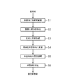
本実施形態に係る冷蔵庫Eは、図1に示すように、外箱33と、外箱33内に収納され、それぞれ内部に貯蔵室を形成する内箱32,31とを備えている。内箱32,31及び外箱33は、共に前方に開口部が形成されている。図1に示す例では、内箱32内の貯蔵室は、冷凍温度帯に設定される冷凍室43であり、内箱31内の貯蔵室は冷蔵温度帯に設定される冷蔵室45である。
(First Embodiment)
<Refrigerator>
As shown in FIG. 1, the refrigerator E according to the present embodiment includes an
冷蔵庫Eの背面部における内箱32,31と外箱33との間には真空断熱材1、冷蔵庫Eの天井部における内箱31と外箱33との間には真空断熱材38、冷蔵庫Eの底部における内箱32と外箱33との間には真空断熱材39が配置されている。また、冷蔵庫Eの両側面部における内箱32,31と外箱33との間にも真空断熱材(図示せず)が配置されている。なお、真空断熱材38,39は、本実施形態に係る真空断熱材であってもよいし、冷蔵庫に一般に用いられる公知の断熱材又は真空断熱材であってもよい。また、冷蔵庫Eの扉、仕切り等にも真空断熱材1を適用してもよい。これにより、さらに断熱性能を向上させることができ、断熱性能や省エネ性能、内容積効率に優れた冷蔵庫を得ることができる。
The vacuum
この内箱32,31、外箱33、真空断熱材1,38,39と、内箱32の開口部を閉塞する引き出し式の扉37、及び内箱31の開口部を閉塞する例えば回転式の扉35とは、断熱箱体40を構成している。外箱33は一部を除いて外部に露出しており、前方の端部で内箱32,31に接続されている。
The
また、本実施形態の冷蔵庫Eは、断熱箱体40に加えて、発泡(硬質)ウレタン34、圧縮機41を含む冷凍サイクル、電気基板及び電気配線とを備える(図示しないものを含む)。外箱33と内箱32,31との間の壁となる空間の適所には、冷凍サイクルにおける冷媒配管の一部や電気配線の一部、真空断熱材1がそれぞれ配設され、それ以外の空間のすべてが発泡ウレタン34又は発泡ポリスチレン等の断熱材で充填されている。それぞれの材質や基材厚さは特に限定されることはなく、例えば、外箱33は鉄やステンレス等、内箱32,31はアクリロニトリル−ブタジエン−スチレン共重合体(ABS)等、冷媒配管は銅やアルミニウム、鉄等、冷媒はR134a、R600a等が使用可能である。
Further, the refrigerator E of the present embodiment includes, in addition to the heat insulating
冷蔵庫Eへの真空断熱材1の配設位置としては、外箱33の内面への貼り付け、内箱32,31の外面への貼り付け、外箱33と内箱32,31の間に外箱33及び内箱32,31に接着等させずに設置のいずれか、またはこれらの組み合わせである。貼り付け手段は、両面テープやホットメルト等の接着剤、粘着剤等を適用可能である。また、ホットメルトの塗布方法にはビード、ロールコート、バーコート、スパイラル等があるが、接着力が十分で且つ、作業上、工程上適切な手段を適宜選択する。
The positions of the vacuum
<真空断熱材>
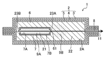
本実施形態に係る真空断熱材1は、図2に示すように、外装体2に収容されたグラスウールやシリカ粉末などの微細空隙を有する芯材6と、容器7と、ガスを吸着する吸着材9とを備える。これらの芯材6、容器7及び吸着材9は、外装体2を構成する2枚の外装材で挟むように内包、密閉するように構成されている。真空断熱材1は、冷蔵庫Eの他に、例えば冷凍庫、給湯容器、自動車用断熱材、建造物用断熱材、自動販売機、保冷箱、保温箱、保冷車等に使用され得る。
<Vacuum heat insulating material>
As shown in FIG. 2, the vacuum
外装体2を構成する外装材は、芯材6を空気や水分から隔離する役割を果たし、ガスバリア性を有する材料であれば、従来の如何なるものも利用できる。例えば、熱可塑性樹脂からなるプラスチックフィルムや金属箔等をラミネート加工することでバリア性を付与したラミネートフィルム等を用いることができる。具体的には、図2に示すように、熱溶着フィルム5と、中間層のガスバリアフィルム4と、最外層の表面保護フィルム3を有する構成とすることができる。熱溶着フィルム5は、例えば、低密度ポリエチレン、直鎖状低密度ポリエチレン、高密度ポリエチレンなどのポリオレフィン、エチレン−酢酸ビニル共重合体等の熱可塑性樹脂、又はこれらの混合物等が挙げられる。ガスバリアフィルム4は、アルミニウムやステンレス等の金属箔や、ポリエチレンテレフタレートフィルムやエチレン−ビニルアルコール共重合体に、アルミニウム等の金属原子や、アルミナやシリカ等の金属酸化物を蒸着したフィルム等が使用できる。表面保護フィルム3は、例えば、ポリアミド(ナイロン)(PA)、ポリエステル、ポリオレフィン、ポリイミド、ポリメチルメタクリレート(PMMA)等が挙げられる。また、外装体2は、上記のようなラミネートフィルムでなくてもよく、例えば、金属容器やガラス容器、樹脂と金属の積層されたガスバリア容器のようなものであってもよい。例えば、ポリ塩化ビニリデン、ポリビニルアルコール、エチレン−ビニルアルコール共重合体、ポリエステル、ポリプロピレン、ポリアミド、ポリエチレン、及びこれらのフィルムに金属蒸着したフィルム、金属箔などを成形した容器等を使用することができる。また、これらの例示したフィルム等の内、一種又は二種以上のフィルムをラミネートしたものを成形してもよい。
The exterior material constituting the
芯材6は、図2に示すように、外装体2の内部に配置されており、真空断熱材1の骨格としての役割を有する。芯材6の材質としては、特に限定されず、公知の材料を使用できる。具体的には、グラスウール、ロックウール、アルミナ繊維、熱伝導率の低い金属からなる金属繊維等の無機繊維;ポリエステルやポリアミド、アクリル、ポリオレフィン、アラミドなどの合成繊維や木材パルプから製造されるセルロース、コットン、麻、ウール、シルクなどの天然繊維、レーヨンなどの再生繊維、アセテートなどの半合成繊維等の有機繊維等が挙げられる。上記芯材材料は、単独で使用されても又は2種以上の混合物であってもよい。これらのうち、断熱性能やコストの観点からグラスウールが好ましい。これらの材料からなる芯材は、繊維自体の弾性が高く、また繊維自体の熱伝導率が低く、なおかつ工業的に安価である。
As shown in FIG. 2, the
外装体2の内部は、断熱性能向上の観点から、外装体2の端に設けられた排気口8から真空引きされて、減圧されている。
From the viewpoint of improving the heat insulating performance, the inside of the
容器7は、図2に示すように、後述する吸着材9Aを保持する役割を有する。容器7としては、例えば不織布やガス透過性フィルム等の通気性のもの、あるいはガスバリアフィルム等の非通気性のものが使用可能である。容器7の材質としては、例えばポリエチレン、ポリプロピレン、ポリエステル、ポリ乳酸等の熱可塑性樹脂、およびそれらの混合物や積層体が挙げられる。容器7の形状は、特に限定されるものではなく、直方体、立方体、球状、袋状等の一般的な容器の形状を採用することができる。
As shown in FIG. 2, the
また、容器7は、酸素ガスの透過率が16g/m2・24h・atm以下である樹脂製の不織布で形成されていることが好ましい。このような特性の不織布を用いることにより、容器7における酸素等のガス透過量を適量にコントロール可能となることで、第1空間21に存在する吸着材9Aの劣化が生じにくくなり、吸着材の長期吸着性能を向上することができる。このような特性の不織布は、例えば、ポリエチレン、ポリプロピレン、及びポリエチレンテレフタレート等の1種又はこれらの混合体により形成することができる。
The
真空断熱材1の内部は、容器7の内面7Aで形成される第1空間21と、容器7の外面7Bと外装体2の内面2Aとで形成される第2空間22とを備える。容器7には、開口部23A,23Bが設けられており、第1空間21と第2空間22はこの開口部23A,23Bによって連通している。なお、図2において、開口部23A,23Bの内周面内の空間は、第1空間21の一部とする。
The inside of the vacuum
開口部23Aは、容器7の面のうち外装体2の排気口8に最も近い面に形成されている。そして、開口部23Bは、開口部23Aが形成されている面に対向する面、言い換えると外装体2の排気口8から最も遠い面に形成されている。開口部23A,23Bはともに円形であり、その直径は、開口部23A,23Bともに同一である。
The
図2に示すように、開口部23Aと開口部23Bとを貫通する軸11が存在する。言い換えると容器7を開口部23A側の面から見たときに、開口部23Aと開口部23Bは重なっており、吸着材9が存在しない場合は開口部23A,23Bを通じて容器7の外側が見える状態となっている。また、軸11は、外装体2の排気口8の吸引方向とも平行になっている(図2では一致している)。
As shown in FIG. 2, there is a
ここに、吸着材9の一部である吸着材9Aは、容器7の内側の第1空間21に存在しており、吸着材9の残りの部分である吸着材9Bは、容器7と外装体2とで形成された第2空間22に存在している。吸着材9Bは、容器7の開口部23Aを通じて第1空間21から第2空間22に分散するように配置されている。
Here, the adsorbent 9A, which is a part of the adsorbent 9, exists in the
本構成によれば、第2空間22に吸着材9Bが分散しているため、真空断熱材1内に含まれるガスを早期に吸着することができる。また、吸着材9Aが容器7内側の第1空間21に存在しているため、第2空間22の吸着材9Bの吸着性能が低下した場合であっても、第1空間21に存在する吸着材9Aにより、開口部23A,23Bを通じて外部から侵入してくるガスを吸着し、長期に亘って吸着材9の吸着性能を維持することができる。
According to this configuration, since the adsorbent 9B is dispersed in the
また、図2に示すように、排気口8に近い側の開口部23A周辺の第2空間22側には、開口部23A近傍における芯材6の除去、又は押し潰し等により、凹部61が形成されている。そして、凹部61から広がるように吸着材9Bが第2空間22に分散している。これにより、開口部23A近傍の凹部61に配置された吸着材9Bがガスと接触しやすくなるから、吸着材9の吸着性能が向上する。
Further, as shown in FIG. 2, a
吸着材9は、ターゲットガスを吸着するガス吸着材、特に水素を吸着する水素吸着材と、水分を吸着する水分吸着材とを含むことが好ましい。以下、詳述する。 The adsorbent 9 preferably contains a gas adsorbent that adsorbs the target gas, particularly a hydrogen adsorbent that adsorbs hydrogen, and a moisture adsorbent that adsorbs water. The details will be described below.
まず、吸着材9は水素吸着材を含むことが好ましい。これは以下の理由による。すなわち、本発明者が鋭意検討したところ、水分吸着材のみを収容した真空断熱材中に残存する主なガスは、窒素、水素、酸素、一酸化炭素及び二酸化炭素であることが分かった。これらの内、水素は窒素、酸素、水と比べて熱伝導率が高い気体であり、真空断熱材中に存在することで熱伝導率の悪化に大きく影響する。また、酸素欠損を有するチタン酸化物又はセリウム酸化物等が水素還元によって製造された場合には、減圧状態でチタン酸化物又はセリウム酸化物等から水素が放出されることが分かった。これは、水素還元により酸素欠損構造を作り出すため、その欠損部分にトラップされた水素が減圧状態における酸素吸着過程でチタン酸化物又はセリウム酸化物等から放出される事によるものである。したがって、真空断熱材中に既述のチタン酸化物又はセリウム酸化物等を適用した場合に水素が放出され、真空断熱材の熱伝導率が却って悪化することがあり得ることが明らかとなった。したがって、本願発明のガス吸着材は、水素吸着成分を含有することが好ましい。水素吸着材と酸素欠損を有するチタン酸化物又はセリウム酸化物等とを同一空間に置くことによって、チタン酸化物又はセリウム酸化物等が酸素を吸着する過程で放出される水素を脱水素材が吸着することによって、存在する微量水素を水に変換し、変換された水は、ガス吸着材に併存する水分吸着材によって吸着され、減圧環境の熱伝導率の劣化を抑えることが可能になる。 First, the adsorbent 9 preferably contains a hydrogen adsorbent. This is due to the following reasons. That is, as a result of diligent studies by the present inventor, it was found that the main gases remaining in the vacuum heat insulating material containing only the water adsorbent are nitrogen, hydrogen, oxygen, carbon monoxide and carbon dioxide. Of these, hydrogen is a gas having a higher thermal conductivity than nitrogen, oxygen, and water, and its presence in the vacuum heat insulating material greatly affects the deterioration of the thermal conductivity. It was also found that when a titanium oxide or cerium oxide having an oxygen deficiency was produced by hydrogen reduction, hydrogen was released from the titanium oxide or cerium oxide under reduced pressure. This is because the oxygen-deficient structure is created by hydrogen reduction, and the hydrogen trapped in the deficient portion is released from the titanium oxide, the cerium oxide, or the like in the oxygen adsorption process in the reduced pressure state. Therefore, it has been clarified that when the above-mentioned titanium oxide, cerium oxide or the like is applied to the vacuum heat insulating material, hydrogen may be released and the thermal conductivity of the vacuum heat insulating material may be deteriorated. Therefore, the gas adsorbent of the present invention preferably contains a hydrogen adsorbing component. By placing the hydrogen adsorbent and the oxygen-deficient titanium oxide or cerium oxide in the same space, the dehydrating material adsorbs the hydrogen released in the process of the titanium oxide or cerium oxide adsorbing oxygen. Thereby, the existing trace amount of hydrogen is converted into water, and the converted water is adsorbed by the water adsorbent coexisting with the gas adsorbent, and it becomes possible to suppress the deterioration of the thermal conductivity in the reduced pressure environment.
水素吸着材は具体的には例えば、酸化パラジウム(II)、酸化亜鉛、パラジウム、チタン、ニッケル、及びマグネシウムのいずれか1種又はこれらの混合物を使用できる。これらの内、特に好ましいものは酸化パラジウム(II)である。酸化パラジウム(II)は、水素を水に変換する。このため、水分吸着材と酸化パラジウム(II)とを合わせてガス吸着材とすることにより、水分だけでなく水素も除去できる吸着材が得られ、真空断熱材内に存在する、又は真空断熱材外部から侵入する水素ガスの吸着性能が向上する。 Specifically, as the hydrogen adsorbent, for example, any one of palladium (II) oxide, zinc oxide, palladium, titanium, nickel, and magnesium, or a mixture thereof can be used. Of these, palladium (II) oxide is particularly preferable. Palladium (II) oxide converts hydrogen into water. Therefore, by combining the water adsorbent and the palladium (II) oxide to form a gas adsorbent, an adsorbent capable of removing not only water but also hydrogen can be obtained, which exists in the vacuum heat insulating material or is a vacuum heat insulating material. The adsorption performance of hydrogen gas entering from the outside is improved.
従って、吸着材9は、真空断熱材1内に存在する、又は真空断熱材1の外部から侵入する水素ガスを吸着させる観点から、酸化パラジウム(II)を含むことが好ましい。吸着材9の総量に対する酸化パラジウム(II)PdOの含有量は、好ましくは0.001質量%以上2.5質量%以下、より好ましくは0.0015質量%以上1質量%以下、特に好ましくは0.002質量%以上0.25質量%以下である。
Therefore, the adsorbent 9 preferably contains palladium (II) oxide from the viewpoint of adsorbing hydrogen gas existing in the vacuum
また、吸着材9は、好ましくは酸素欠損した金属酸化物を含み、具体的には例えば酸素欠損した酸化チタンTiO2−x(x:0.1以上0.5以下)、酸素欠損した酸化セリウムCeO2−x(x:0.1以上0.7以下)を含む。これにより、真空断熱材1内に存在する、又は真空断熱材1の外部から侵入する酸素ガス等の吸着性能が向上する。吸着材9の総量における酸素欠損した金属酸化物の含有量は、好ましくは0.01質量%以上25質量%以下、より好ましくは0.05質量%以上2.5質量%以下、特に好ましくは0.1質量%以上0.25質量%以下である。
Further, the adsorbent 9 preferably contains an oxygen-deficient metal oxide, specifically, for example, oxygen-deficient titanium oxide TiO 2-x (x: 0.1 or more and 0.5 or less), oxygen-deficient cerium oxide. Includes CeO 2-x (x: 0.1 or more and 0.7 or less). As a result, the adsorption performance of oxygen gas or the like existing in the vacuum
酸素欠損を有するチタン酸化物又はセリウム酸化物等の酸素吸着速度はとても大きく、粉体のまま大気中に出すと吸着熱により発熱し、大気中の酸素との反応で発火する虞がある。これに対して、樹脂とチタン酸化物又はセリウム酸化物等との混合物や二酸化炭素によるキャッピングにより、対処する手法も知られている。しかしながら、減圧下においては、樹脂との混合物は、樹脂からのアウトガスが発生し、二酸化炭素によるキャッピングも同様に二酸化炭素がアウトガスになる可能性が高い。 The oxygen adsorption rate of titanium oxide or cerium oxide having oxygen deficiency is very high, and if the powder is put out into the atmosphere as it is, it will generate heat due to the heat of adsorption and may ignite due to the reaction with oxygen in the atmosphere. On the other hand, a method of dealing with this by capping with a mixture of a resin and a titanium oxide or a cerium oxide or carbon dioxide is also known. However, under reduced pressure, the mixture with the resin generates outgas from the resin, and there is a high possibility that carbon dioxide becomes outgas in the capping by carbon dioxide as well.
したがって、チタン酸化物又はセリウム酸化物等を真空断熱材に挿入する以前での大気中でのハンドリングの問題点が存在する。そこで、チタン酸化物又はセリウム酸化物等を水分吸着材と混合する、チタン酸化物又はセリウム酸化物等の核を水分吸着材で覆う有核錠の形態を利用する等で酸素欠損を有するチタン酸化物又はセリウム酸化物等と酸素との反応を律速させることができる。 Therefore, there is a problem of handling in the atmosphere before inserting titanium oxide, cerium oxide or the like into the vacuum heat insulating material. Therefore, titanium oxidation having oxygen deficiency is achieved by mixing titanium oxide or cerium oxide with a water adsorbent, or by using a nucleated tablet in which the nucleus of titanium oxide or cerium oxide is covered with a water adsorbent. The reaction between an object or a cerium oxide and oxygen can be rate-determining.
さらに、吸着材9は、真空断熱材1内に存在する、又は真空断熱材1の外部から侵入する窒素ガスを吸着させる観点から、窒素吸着能を有する材料を含有してもよい。具体的には例えば、Li、V及びZrの少なくとも一種、例えば、金属Li、及び/又は、Li合金である。Li合金の中でもLiとアルカリ土類金属との合金、特に、Li−Ba合金が窒素の吸収特性が高いことから好ましい。吸着材9における上記金属の含有量は、好ましくは0.01質量%以上2.5質量%以下、より好ましくは0.1質量%以上2.0質量%以下、特に好ましくは1.3質量%以上1.6質量%以下である。なお、これらの金属は水分により不活性化され得るため、上述の酸化カルシウム等の吸水性材料と併用することが好ましい。
Further, the adsorbent 9 may contain a material having a nitrogen adsorbing ability from the viewpoint of adsorbing nitrogen gas existing in the vacuum
また、吸着材9は、真空断熱材1内に存在する、又は真空断熱材1の外部から侵入する水分を吸着させる観点から、水分吸着能を有する吸水性材料、すなわち水分吸着材を含むことが好ましい。
Further, the adsorbent 9 may include a water-absorbent material having a moisture-adsorbing ability, that is, a moisture adsorbent, from the viewpoint of adsorbing moisture existing in the vacuum
水分吸着材は、格別限定されるものではないが、化学的な水分吸着材であるアルカリ土類酸化物が好ましい。アルカリ土類酸化物は、具体的には例えば、酸化カルシウム、酸化マグネシウム、酸化ストロンチウム、及び酸化バリウムのいずれか1種又はこれらの混合物である。特に、酸化カルシウムは、水蒸気圧の極めて低い環境においても水分を吸着することができ、且つコスト面においても好ましい。酸化カルシウムは、比表面積が大きい方が水分を吸着しやすいと予想される。しかし、本発明者が検討した結果、酸化パラジウム(II)と組み合わせて水素の除去も行う場合には、ある程度比表面積が小さい方が良いことが明らかとなった。具体的に、酸化カルシウムの比表面積を10m2/g未満にすることにより、比表面積が大きい酸化カルシウムを用いる場合と比べて、真空断熱材内部の水素濃度を大幅に低減できる。酸化カルシウムの比表面積はBET法により測定することができる。このような比表面積の酸化カルシウムを得るために、酸化カルシウムの平均1次粒子径は1μm以下であることが好ましい。 The water adsorbent is not particularly limited, but an alkaline earth oxide which is a chemical water adsorbent is preferable. The alkaline earth oxide is specifically, for example, any one of calcium oxide, magnesium oxide, strontium oxide, and barium oxide, or a mixture thereof. In particular, calcium oxide can adsorb water even in an environment where the water vapor pressure is extremely low, and is preferable in terms of cost. It is expected that the larger the specific surface area of calcium oxide, the easier it is to adsorb water. However, as a result of the study by the present inventor, it has been clarified that when hydrogen is also removed in combination with palladium (II) oxide, it is better to have a small specific surface area to some extent. Specifically, by setting the specific surface area of calcium oxide to less than 10 m 2 / g, the hydrogen concentration inside the vacuum heat insulating material can be significantly reduced as compared with the case of using calcium oxide having a large specific surface area. The specific surface area of calcium oxide can be measured by the BET method. In order to obtain calcium oxide having such a specific surface area, the average primary particle size of calcium oxide is preferably 1 μm or less.
また、物理的な水分吸着材を使用することもできる。物理的な水分吸着材としては、例えばゼオライト、アルミナ及びシリカゲル等の少なくとも1つを用いることができ、中でもゼオライトが好ましい。ゼオライトは特に限定されないが、例えば、多孔性結晶性アルミノケイ酸塩からなり、ゼオライト骨格中のシリカ対アルミナ比(Si/Al)が1〜1500、好ましくは5〜1000、さらに好ましくは5.5〜500であるものを用いることができる。 It is also possible to use a physical moisture adsorbent. As the physical moisture adsorbent, for example, at least one of zeolite, alumina, silica gel and the like can be used, and zeolite is particularly preferable. Zeolites are not particularly limited, but are, for example, made of porous crystalline aluminosilicate, and the silica to alumina ratio (Si / Al) in the zeolite skeleton is 1 to 1500, preferably 5 to 1000, and more preferably 5.5 to 5. Those that are 500 can be used.
吸着材9における水分吸着材の含有量は、好ましくは75質量%以上99.999質量%以下、より好ましくは95質量%以上99.99質量%以下、特に好ましくは99.5質量%以上99.9質量%以下である。 The content of the water adsorbent in the adsorbent 9 is preferably 75% by mass or more and 99.99% by mass or less, more preferably 95% by mass or more and 99.99% by mass or less, and particularly preferably 99.5% by mass or more and 99. It is 9% by mass or less.
また、吸着材9は、遷移金属酸化物及びパラジウムの混合物を含んでもよい。このとき、パラジウムの量は遷移金属酸化物に対して、好ましくは0.2質量%以上2質量%以下、より好ましくは0.3質量%以上1.9質量%以下、特に好ましくは0.4質量%以上1.8質量%以下である。また、遷移金属酸化物は酸化セリウム及び酸化銅を含んでもよい。このとき、酸化銅の含有量は、遷移金属酸化物の全質量に対して、好ましくは5質量%以上50質量%以下、より好ましくは7質量%以上30質量%以下、特に好ましくは10質量%以上20質量%以下の範囲である。これにより、真空断熱材1内に存在する、又は真空断熱材1の外部から侵入する水素ガス及び一酸化炭素ガスを吸着することができる。
Further, the adsorbent 9 may contain a mixture of a transition metal oxide and palladium. At this time, the amount of palladium is preferably 0.2% by mass or more and 2% by mass or less, more preferably 0.3% by mass or more and 1.9% by mass or less, and particularly preferably 0.4 with respect to the transition metal oxide. It is mass% or more and 1.8 mass% or less. Further, the transition metal oxide may contain cerium oxide and copper oxide. At this time, the content of copper oxide is preferably 5% by mass or more and 50% by mass or less, more preferably 7% by mass or more and 30% by mass or less, and particularly preferably 10% by mass, based on the total mass of the transition metal oxide. It is in the range of 20% by mass or less. As a result, hydrogen gas and carbon monoxide gas existing in the vacuum
なお、遷移金属酸化物の比表面積は、好ましくは5m2/g以上50m2/g以下、より好ましくは7m2/g以上48m2/g以下、特に好ましくは10m2/g以上45m2/g以下である。これにより、真空断熱材1内に存在する、又は真空断熱材1の外部から侵入する水素ガス及び一酸化炭素ガスの吸着容量が増大する。
The specific surface area of the transition metal oxide is preferably 5 m 2 / g or more and 50 m 2 / g or less, more preferably 7 m 2 / g or more and 48 m 2 / g or less, and particularly preferably 10 m 2 / g or more and 45 m 2 / g. It is as follows. As a result, the adsorption capacity of the hydrogen gas and the carbon monoxide gas existing in the vacuum
吸着材9は水酸化リチウム又は水酸化カルシウムよりなる群から選択される少なくとも一つの金属水酸化物をさらに含んでもよい。このとき、金属水酸化物の含有量は遷移金属酸化物及び金属パラジウムの混合物に対して、好ましくは50質量%以上95質量%以下、より好ましくは55質量%以上90質量%以下、特に好ましくは60質量%以上85質量%以下である。これにより、真空断熱材1内に存在する、又は真空断熱材1の外部から侵入する水素ガス及び一酸化炭素ガスの吸着容量が増大する。
The adsorbent 9 may further contain at least one metal hydroxide selected from the group consisting of lithium hydroxide or calcium hydroxide. At this time, the content of the metal hydroxide is preferably 50% by mass or more and 95% by mass or less, more preferably 55% by mass or more and 90% by mass or less, particularly preferably, with respect to the mixture of the transition metal oxide and the metal palladium. It is 60% by mass or more and 85% by mass or less. As a result, the adsorption capacity of the hydrogen gas and the carbon monoxide gas existing in the vacuum
また、吸着材9は前記遷移金属酸化物及びパラジウムの混合物に加えてさらに上述のような水分吸着材を含んでもよい。前記遷移金属酸化物及びパラジウムの混合物の含有量は、水分吸着材に対して、好ましくは0.8質量%以上5質量%以下、より好ましくは1.0質量%以上4.5質量%以下、特に好ましくは1.2質量%以上4.0質量%以下である。これにより、真空断熱材1内に存在する、又は真空断熱材1の外部から侵入する水、水蒸気、水素ガス及び一酸化炭素ガスの吸着容量が増大する。
Further, the adsorbent 9 may further contain the above-mentioned water adsorbent in addition to the mixture of the transition metal oxide and palladium. The content of the mixture of the transition metal oxide and palladium is preferably 0.8% by mass or more and 5% by mass or less, more preferably 1.0% by mass or more and 4.5% by mass or less, based on the water adsorbent. Particularly preferably, it is 1.2% by mass or more and 4.0% by mass or less. As a result, the adsorption capacities of water, water vapor, hydrogen gas and carbon monoxide gas existing in the vacuum
<真空断熱材の製造方法>
図3に示すように、吸着材9を準備し、開口部23A,23Bを形成する前の容器7に吸着材9を配置する(S1)。吸着材9は、上述の材料を例えば自動乳鉢、混合ミル、ボールミル等の一般的な公知の手段を用いて混合させて用いることができる。なお、この工程は、アルゴンガス下などの不活性ガス雰囲気下で行うことが好ましい。また、吸着材9の総量に対する各材料の含有量が小さい場合には、各材料を数十倍にスケールアップして混合した後、混合物から必要量の吸着材9を秤量して用いるようにしてもよい。
<Manufacturing method of vacuum heat insulating material>
As shown in FIG. 3, the adsorbent 9 is prepared, and the adsorbent 9 is placed in the
そして、工程S1において、吸着材9を配置した容器7に開口部23A,23Bを例えば穴あけ用治具等を用いて形成する(S2)。
Then, in step S1,
次に、外装体2の内部に芯材6を配置し、容器7が設置される予定の位置の、開口部23A周辺に該当する部分の芯材6を所定量取り除く、又は他の領域へ押しよけることにより、凹部61を形成する(S3)。
Next, the
そして、図4に示すように、開口部23A,23Bを形成した容器7を上記外装体2の内部の所定位置に配置する(S4)。なお、開口部23Aが排気口8に最も近くなり且つ開口部23A,23Bを貫通する軸11が真空排気の吸引方向と略平行(一致)になるように、容器7を配置する。
Then, as shown in FIG. 4, the
最後に、外装体2内の気体を例えば真空ポンプなどで開放された排気口8から排気し(S5)、排気口8を閉じて外装体2を封止する(S6)。
Finally, the gas in the
ここに、工程S5において、図4に示すように、真空排気の吸引力により、吸着材9は容器7の内側の第1空間21から開口部23Aを通じて第2空間22に露出、分散される。
Here, in step S5, as shown in FIG. 4, the adsorbent 9 is exposed and dispersed from the
上述のごとく、真空排気の吸引方向と、開口部23A,23Bを貫通する軸11とは略平行であるため、排気口8から遠い方の開口部23Bから近い方の開口部23Aに向かって、真空断熱材1内に気体の流れが生じ、第1空間21に収納された吸着材9が排気口8に近い方の開口部23Aを通じて第2空間22内に効果的に分散される。
As described above, since the suction direction of the vacuum exhaust is substantially parallel to the
このように、容器7の開口部23Aから第2空間22に露出、分散した吸着材9Bにより、真空断熱材1内部に存在するガスを早急に吸着させて、真空断熱材1の初期性能・短期性能を向上させることができる。また、容器7内側の第1空間21に残った吸着材9Aは、第2空間22の吸着材9Bの吸着性能が低下した後であっても、真空断熱材1の外部から内部に入ってくるガスを長期に亘り吸着させることができるので、真空断熱材1の長期性能を向上させることができる。
In this way, the gas existing inside the vacuum
なお、真空排気の速度は、特に限定されるものではないが、初速度を約200m3/h、最大速度を約400m3/hとすることができる。また、真空断熱材1内の真空度は、断熱性能向上の観点から、好ましくは1Pa以下、より好ましくは0.1Pa以下、特に好ましくは0.01Pa以下である。
The speed of vacuum exhaust is not particularly limited, but the initial speed can be about 200 m 3 / h and the maximum speed can be about 400 m 3 / h. The degree of vacuum in the vacuum
また、吸着材9は、工程S5における第2空間22への分散性向上の観点から、好ましくは粉末状であり、吸着材9の平均粒子径は好ましくは0.1μm以上500μm以下、より好ましくは1μm以上300μm以下、特に好ましくは10μm以上100μm以下である。なお、ここでいう粒子径とは、おおよそ二次粒子径を指している。
Further, the adsorbent 9 is preferably in the form of powder from the viewpoint of improving the dispersibility in the
吸着材9の全量に対する第2空間22に分散した吸着材9Bの量の割合(以下、「分散率」という。)は、真空断熱材1の短期性能と長期性能をともに向上させる観点から、好ましくは5質量%以上60質量%未満、より好ましくは5質量%以上50質量%以下、特に好ましくは10質量%以上25質量%以下である。吸着材9Bの量が5質量%未満では、吸着材9Bの短期性能が十分に発揮されず、60質量%以上では、吸着材9の長期性能が向上しない。
The ratio of the amount of the adsorbent 9B dispersed in the
なお、工程S2で形成する開口部23の形状は、特に限定されるものではないが、円形、矩形等の形状とすることができる。また、図4で示す容器7において、容器7の上面から側面を通って下面に亘って略半円筒状や略直方体状にくりぬくような構成にしてもよい。このとき、容器7の展開図における開口部23の最大径、すなわち例えば開口部23が円形の場合は直径、矩形の場合は対角線の長さ、楕円・長円の場合は長径等で表される開口部23の最大の幅は、好ましくは3mm以上35mm以下、より好ましくは4mm以上34mm以下、特に好ましくは5mm以上33mm以下である。
The shape of the
具体的には例えば、後述する実施例にあるように、図6に示すような容器7を用いてもよい。このとき、図7〜図9に示すように、略半円筒状の開口部23A,23Bを形成することができる。略半円筒状の開口部23A,23Bは、図7〜図9に示すように、開口径d及び最大径Dを有する。このとき、図9の展開図において、ヒートシール部75は展開していない。また容器7の上面に形成される開口は開口径dの半円となっている。図8,図9に示す開口部23Aにおいて、最大径Dは、以下の式(1)により算出できる。
Specifically, for example, as shown in Examples described later, a
D=(d/2)×2+2h+k ・・・(1)
但し、式(1)において、hは側面71の高さ、kはヒートシール部の厚さを示す。
D = (d / 2) × 2 + 2h + k ・ ・ ・ (1)
However, in the formula (1), h indicates the height of the
また、開口部23A,23Bを形成する際には、図7に示すように、L1の形状でくりぬいてもよいし、L2の形状でくりぬいてもよい。なお、図7〜図9では、開口部23A,23Bは同一形状同一寸法で形成されているが、開口部23Aの最大径(あるいは面積)は開口部23Bの最大径(あるいは面積)と異なる構成とし、異なる形状異なる寸法で形成してもよい。これにより、工程S5の真空排気時に、開口部23からの吸着材9の分散が促進され得る。
Further, when forming the
工程S3で形成する凹部61の形状は、特に限定されるものではないが、開口部23の周辺に略半球状や略直方体状に形成することができる。凹部61の大きさは、吸着材9の吸着性能及び真空断熱材1の断熱性能の両立の観点から、開口部23の大きさと同程度かそれ以上であり、容器7における開口部23を有する面の表面積よりも小さいことが好ましい。凹部61を形成することにより、容器7の開口部23近傍に配置される芯材6の量が減少し、又は無くなるため、第1空間21に位置していた吸着材9が開口部23を通じて第2空間22に広がりやすくなる。
The shape of the
(第2実施形態)
上記実施形態の真空断熱材1において、容器7は2つの開口部23A,23Bを備えていたが、図5に示すように、開口部23を1つだけ設ける構成としてもよい。また、開口部23を設ける位置は、外装体2の排気口8側に限らず、容器7のいずれの面に形成してもよい。具体的には例えば、図6に示すように、容器7の面72に開口部23を設け、図5に示すように、真空排気の吸引方向に対して開口部23の開口方向が垂直方向を向くように設置してもよい。
(Second Embodiment)
In the vacuum
本構成によれば、開口部23を1つだけ形成するから、工程S2,S4における作業性が向上する。また、工程S4において容器7を外装体2内に設置する際に、排気口8の方向と合わせる必要がないので、容器7の設置方向を気にすることなく容易に設置することができる。
According to this configuration, since only one
(第3実施形態)
第1〜第2実施形態では、開口部23は2つ又は1つ形成する構成であったが、3つ以上の複数の開口部を設けてもよい。具体的には例えば、最大径3mm程度の小さな開口部を多数設ける構成としてもよい。これにより、工程S4において容器7を外装体2内に設置する際に、容器7の内部から吸着材9がこぼれにくく、作業性が向上する。
(Third Embodiment)
In the first and second embodiments, the
開口部23の態様によらず、容器7の外面7Bの総表面積に対する、開口部23の面積の割合(以下、「面積率」という。)は、好ましくは2%以上40%以下、より好ましくは3%以上30%以下、特に好ましくは4%以上20%以下である。これにより、吸着材9Aと吸着材9Bの割合を調節し、吸着材9の短期性能及び長期性能をともに向上させることができる。
Regardless of the aspect of the
本構成の場合、吸着材9Bは、形成された多数の開口部のうちの少なくとも一部から第2空間22に分散していればよい。
In the case of this configuration, the adsorbent 9B may be dispersed in the
(第4実施形態)
第1〜第3実施形態では、真空断熱材1内に、吸着材9を収容する容器7を1個設置する構成であったが、真空断熱材1内に、吸着材9を収納する容器7を複数個設置する構成としてもよい。これにより、開口部の数も増加させることができ、真空断熱材1内の広範囲に亘って吸着材9Bを分散させることができるので、吸着材9Bの分散性が効果的に向上する。容器7同士は近くに設置されても遠くに設置されてもよいが、離して設置して吸着材9Bをそれぞれにおいて分散する場合、吸着の効率が更に向上する。なお、容器7を複数個設置する場合には、上記工程S3において、それぞれの容器7の設置場所に応じて複数の凹部61を形成しておくことが好ましい。
(Fourth Embodiment)
In the first to third embodiments, one
(その他の実施形態)
上記第1〜第4実施形態において、真空断熱材1は、外装体2の内部が減圧されたものであったが、真空引きを行わず、外装体2の内外で常圧の一般的な断熱材として構成することもできる。この場合、吸着材9Aを収納する容器7を外装体2内に配置させるとともに、吸着材9Bを芯材6内に分散させて配置させ、工程S5を省略することにより断熱材を製造することができる。また、常圧の断熱材の製造方法として、上記工程S5において真空排気を行って吸着材9Bを分散させた後に、外装体2内部をアルゴン等の不活性ガスで大気開放して常圧に戻した後、外装体2を封止することにより、常圧の断熱材を製造してもよい。これにより、熱伝導率が空気に対して大きい気体等や吸湿した水等が断熱材内部の空隙に侵入しても、断熱性能の低下(熱伝導率の増大)を抑制可能であり、断熱材の短期性能と長期性能をともに向上させ得る。このような常圧の断熱材は、特に、保冷性能等を必要としない自動車用断熱材、建造物用断熱材等に好適に用いることができる。
(Other embodiments)
In the first to fourth embodiments, the vacuum
次に、具体的に実施した実施例について説明する。 Next, a specific embodiment will be described.
実施例1〜7及び比較例1〜7の真空断熱材のサンプルを作製し、試料作製から7日後及び加速試験後の熱伝導率を測定して、真空断熱材の性能を評価した。結果を表1に示す。 Samples of the vacuum heat insulating materials of Examples 1 to 7 and Comparative Examples 1 to 7 were prepared, and the thermal conductivity was measured 7 days after the sample preparation and after the acceleration test to evaluate the performance of the vacuum heat insulating material. The results are shown in Table 1.

<真空断熱材サンプルの作製>
[実施例1]
Arガス雰囲気下、吸着材として、酸化カルシウムCaO(平均粒子径50μm、BET比表面積5m2/g、吉澤石灰工業製)120g(99.783質量%)、酸素欠損した酸化チタンTiO2−x(平均粒子径10μm、赤穂化成製Tilack NUT)258mg(0.215質量%)、酸化パラジウムPdO(平均粒子径10μm、和光純薬工業製)3.0mg(0.002質量%)の粉末をそれぞれ秤量し、乳鉢に入れてめん棒で混合させた。
<Preparation of vacuum heat insulating material sample>
[Example 1]
Under Ar gas atmosphere, as an adsorbent, calcium oxide CaO (
上記吸着材のうち4.0087gを秤量し、図6に示すような略直方体袋状の不織布容器(幅67mm、長さ67mm、厚さ3mm、ヒートシール幅10mm、ヒートシール部75を除く外面の総表面積4982mm2、ミラクロンPM−30D、山中産業製)に入れて封をした後、図7〜図9に示すように、対向する2つの面71,74に1つずつ開口径dが8mm、最大径Dが11mmとなる略半円筒状の開口部を、穴あけ用治具で切り抜いて形成した。
Of the above adsorbent, 4.087 g is weighed, and the outer surface of the non-woven fabric container (width 67 mm, length 67 mm,
別途、芯材としてグラスウール積層体を準備し、上記吸着材を入れた容器を配置する位置の開口部周辺のグラスウールを切り取って凹部を形成した。乾燥炉でグラスウール積層体を乾燥後、上記吸着材を入れた容器を、最大径11mmの開口部が排気口に向かうように所定位置に配置した。 Separately, a glass wool laminate was prepared as a core material, and the glass wool around the opening at the position where the container containing the adsorbent was placed was cut out to form a recess. After drying the glass wool laminate in a drying oven, the container containing the adsorbent was placed at a predetermined position so that the opening having a maximum diameter of 11 mm faces the exhaust port.
表面保護フィルム3をポリアミド(PA)15μm、ガスバリアフィルム4をアルミニウム蒸着されたポリエチレンテレフタレートフィルム(vmPET)12μm及びアルミニウム箔(AL)7μm、熱溶着フィルム5を直鎖状低密度ポリエチレン(LLDPE)50μmとしたラミネートフィルムと、ガスバリアフィルム4をアルミニウム蒸着されたポリエチレンテレフタレートフィルム(vmPET)12μm×3枚、熱溶着フィルム5を直鎖状低密度ポリエチレン(LLDPE)50μmとしたラミネートフィルムとで構成され、各々の熱溶着フィルム5同士をヒートシール(熱溶着)して袋状に形成した外装体を乾燥炉で乾燥した後、外装体内に上記吸着材を入れた容器が配置されたグラスウール積層体を挿入した。
The surface
最後に、排気口から外装体内の気体を真空ポンプ(LEYVAC LV80、WSU501及びWAU501、Leybold Vacuum社製)を用いて初速度約200m3/hで排気し、真空チャンバー内の真空度が0.01Paとなってから15分後に、排気口をヒートシールにより密閉して真空断熱材を作製した。 Finally, the gas inside the exterior is exhausted from the exhaust port using a vacuum pump (LEYVAC LV80, WSU501 and WAU501, manufactured by Leebold Vacuum) at an initial speed of about 200 m 3 / h, and the degree of vacuum in the vacuum chamber is 0.01 Pa. After 15 minutes, the exhaust port was sealed with a heat seal to prepare a vacuum heat insulating material.
[実施例2]
開口部の開口径dを20mm、最大径Dを23mmとした以外は、実施例1と同様にサンプルを作製した。
[Example 2]
A sample was prepared in the same manner as in Example 1 except that the opening diameter d of the opening was 20 mm and the maximum diameter D was 23 mm.
[実施例3]
開口部の開口径dを30mm、最大径Dを33mmとした以外は、実施例1と同様にサンプルを作製した。
[Example 3]
A sample was prepared in the same manner as in Example 1 except that the opening diameter d of the opening was 30 mm and the maximum diameter D was 33 mm.
[実施例4]
吸着材のうち2.00435gを秤量して不織布容器に入れ、開口部の開口径dを26.5mm、最大径Dを29.5mmとして、これを2個設置した以外は、実施例1と同様にサンプルを作製した。
[Example 4]
Of the adsorbent, 2.00435 g was weighed and placed in a non-woven fabric container, the opening diameter d of the opening was 26.5 mm, the maximum diameter D was 29.5 mm, and the same as in Example 1 except that two of them were installed. A sample was prepared in.
[実施例5]
吸着材のうち2.00435gを秤量して不織布容器に入れ、開口部の開口径dを30mm、最大径Dを33mmとして、これを2個設置した以外は、実施例1と同様にサンプルを作製した。
[Example 5]
Of the adsorbent, 2.00435 g was weighed and placed in a non-woven fabric container, and a sample was prepared in the same manner as in Example 1 except that the opening diameter d of the opening was 30 mm and the maximum diameter D was 33 mm, and two of them were installed. did.
[実施例6]
図6の符号72で示す面に、直径3mmの円形の開口部を30箇所形成した以外は、実施例1と同様にサンプルを作製した。
[Example 6]
A sample was prepared in the same manner as in Example 1 except that 30 circular openings having a diameter of 3 mm were formed on the surface indicated by
[実施例7]
図6の符号72で示す面に、対角線の長さが28.3mm(一辺の長さが20mm)の正方形の開口部を1つ形成した以外は、実施例1と同様にサンプルを作製した。
[Example 7]
A sample was prepared in the same manner as in Example 1 except that one square opening having a diagonal length of 28.3 mm (one side length of 20 mm) was formed on the surface indicated by
[比較例1]
開口部を設けない構成とした以外は、実施例1と同様にサンプルを作製した。
[Comparative Example 1]
A sample was prepared in the same manner as in Example 1 except that the structure was not provided with an opening.
[比較例2]
開口部を設けない構成とし、且つ、吸着材として酸化カルシウムCaOのみ4gを用いた以外は、実施例1と同様にサンプルを作製した。
[Comparative Example 2]
A sample was prepared in the same manner as in Example 1 except that the structure was not provided with an opening and 4 g of calcium oxide CaO was used as an adsorbent.
[比較例3]
吸着材のうち2.00435gを秤量して不織布容器に入れ、開口部の開口径dを34mm、最大径Dを37mmとして、これを2個設置した以外は、実施例1と同様にサンプルを作製した。
[Comparative Example 3]
Of the adsorbent, 2.00435 g was weighed and placed in a non-woven fabric container, and a sample was prepared in the same manner as in Example 1 except that the opening diameter d of the opening was 34 mm and the maximum diameter D was 37 mm, and two of them were installed. did.
[比較例4]
吸着材のうち2.00435gを秤量して不織布容器に入れ、開口部の開口径dを38mm、最大径Dを41mmとして、これを2個設置した以外は、実施例1と同様にサンプルを作製した。
[Comparative Example 4]
Of the adsorbent, 2.00435 g was weighed and placed in a non-woven fabric container, and a sample was prepared in the same manner as in Example 1 except that the opening diameter d of the opening was 38 mm and the maximum diameter D was 41 mm, and two of them were installed. did.
[比較例5]
図6の符号72で示す面に、直径2mmの円形の開口部を1つ形成した以外は、実施例1と同様にサンプルを作製した。
[Comparative Example 5]
A sample was prepared in the same manner as in Example 1 except that one circular opening having a diameter of 2 mm was formed on the surface indicated by
[比較例6]
開口部の開口径dを40mm、最大径Dを43mmの半円筒状とした以外は、実施例1と同様にサンプルを作製した。
[Comparative Example 6]
A sample was prepared in the same manner as in Example 1 except that the opening diameter d of the opening was 40 mm and the maximum diameter D was 43 mm in a semi-cylindrical shape.
[比較例7]
図6の符号72で示す面に、直径10mmの円形の開口部を1つ形成し、吸着材を平均粒子径2000μmのビーズ(シリカゲル、三菱化学アナリテック社製)とした以外は、実施例1と同様にサンプルを作製した。
[Comparative Example 7]
Example 1 except that one circular opening having a diameter of 10 mm was formed on the surface indicated by
<吸着材の分散率について>
作製した真空断熱材サンプルについて、作製直後のサンプルの外装体を開封し、吸着材を含む容器の質量を秤量することにより、当初容器内に収容した吸着材の質量(総量)及び作製前後での質量差から容器内に残存する吸着材の質量と容器外に分散したと考えられる吸着材の質量を算出し、吸着材の総量に対する容器外に分散した吸着材の質量の割合を百分率で算出した。
<Dispersion rate of adsorbent>
For the prepared vacuum heat insulating material sample, by opening the outer body of the sample immediately after preparation and weighing the mass of the container containing the adsorbent, the mass (total amount) of the adsorbent initially contained in the container and before and after the production From the mass difference, the mass of the adsorbent remaining in the container and the mass of the adsorbent considered to be dispersed outside the container were calculated, and the ratio of the mass of the adsorbent dispersed outside the container to the total amount of the adsorbent was calculated as a percentage. ..
<加速試験について>
作製した真空断熱材のサンプルに対し、下記条件A,Bのサイクル試験を恒温恒湿槽(SSE−47TX−A、カトー社製)を用いて行った。
条件A:−30℃、2.5時間
条件B:80℃、65%RH、5.5時間
条件A、昇温、条件B、降温の順で実施したものを1サイクルとし、これを28サイクル行った。
<About accelerated test>
The cycle test of the following conditions A and B was performed on the prepared sample of the vacuum heat insulating material using a constant temperature and humidity chamber (SSE-47TX-A, manufactured by Kato Co., Ltd.).
Condition A: -30 ° C, 2.5 hours Condition B: 80 ° C, 65% RH, 5.5 hours Condition A, temperature rise, condition B, and temperature decrease are performed in this order as one cycle, and this is 28 cycles. gone.
<熱伝導率の測定>
作製した真空断熱材のサンプル(幅290mm、長さ410mm、厚さ12mm)について、
熱伝導率測定装置(NETZSCH社製、HFM436、JIS A 1412−2(熱流計法)に準拠)を用い、高温側38℃、低温側10℃(平均温度24℃、ΔT=28K)の条件で、外装体においてアルミニウム箔を含むラミネートフィルム側を低温側として熱伝導率を測定した。測定は、真空断熱材のサンプルを作製後7日間経過後と、上記加速試験後に行った。
<Measurement of thermal conductivity>
About the prepared sample of vacuum heat insulating material (width 290 mm, length 410 mm, thickness 12 mm)
Using a thermal conductivity measuring device (manufactured by NETZSCH, HFM436, JIS A 1414-2 (heat flow meter method)), under the conditions of 38 ° C on the high temperature side and 10 ° C on the low temperature side (average temperature 24 ° C, ΔT = 28K). In the exterior body, the thermal conductivity was measured with the laminated film side containing the aluminum foil as the low temperature side. The measurement was performed 7 days after the sample of the vacuum heat insulating material was prepared and after the acceleration test.
なお、表1では、比較例1の真空断熱材のサンプルを作製後7日間経過後に測定した熱伝導率の測定値を100とし、それぞれのサンプルの測定値をその相対値である熱伝導率指数として示した。 In Table 1, the measured value of the thermal conductivity measured 7 days after the sample of the vacuum heat insulating material of Comparative Example 1 was prepared is set to 100, and the measured value of each sample is the relative value of the thermal conductivity index. Shown as.
<作業性>
図3の工程S2及び工程S4における作業性を示す。開口部の形成の容易さ及び開口部を形成後の容器の外装体への設置の時の作業性を、「◎(非常に良い)」「○(良い)」、「△(普通)」「×(悪い)」の4段階で評価した。
<Workability>
The workability in the process S2 and the process S4 of FIG. 3 is shown. The ease of forming the opening and the workability when installing the container on the exterior body after forming the opening are described as "◎ (very good)""○(good)","△(normal)"" It was evaluated on a four-point scale of "x (bad)".
<考察>
表1に示すように、開口部を設けない構成の比較例1,2の真空断熱材サンプルに対し、実施例1〜5のサンプルでは、熱伝導率指数が作製7日後及び加速試験後の双方で減少することが判った。このことから、容器に開口部を設け、吸着材を第2空間に分散させることにより、真空断熱材の短期性能及び長期性能の両方が向上することが判った。
<Discussion>
As shown in Table 1, in contrast to the vacuum heat insulating material samples of Comparative Examples 1 and 2 having no opening, in the samples of Examples 1 to 5, the thermal conductivity index was obtained both after 7 days of preparation and after the acceleration test. It turned out to decrease in. From this, it was found that both the short-term performance and the long-term performance of the vacuum heat insulating material are improved by providing an opening in the container and dispersing the adsorbent in the second space.
実施例1〜5及び比較例1,3,4のサンプルについて、吸着材の分散率に対する熱伝導率指数を図10,11に示す。分散率が5%〜50%の実施例1〜5では、作製7日後及び加速試験後の熱伝導率指数はともに比較例1よりも低い値となり、短期性能及び長期性能のいずれも向上することが判った。分散率が60%の比較例3では、作製7日後の熱伝導率指数は比較例1よりも低いものの、加速試験後の熱伝導率指数は比較例1よりも高い値となり、短期性能は向上するものの長期性能は比較例1より悪化傾向にあることが判った。 For the samples of Examples 1 to 5 and Comparative Examples 1, 3 and 4, the thermal conductivity index with respect to the dispersion rate of the adsorbent is shown in FIGS. 10 and 11. In Examples 1 to 5 having a dispersion rate of 5% to 50%, both the thermal conductivity index after 7 days of preparation and after the accelerated test are lower than those of Comparative Example 1, and both short-term performance and long-term performance are improved. I found out. In Comparative Example 3 having a dispersion rate of 60%, the thermal conductivity index after 7 days of preparation was lower than that of Comparative Example 1, but the thermal conductivity index after the accelerated test was higher than that of Comparative Example 1, and the short-term performance was improved. However, it was found that the long-term performance tended to be worse than that of Comparative Example 1.
分散率が75%の比較例4では、加速試験後の熱伝導率指数は比較例1,3よりもさらに高い値となり、長期性能は向上しないことが判った。 In Comparative Example 4 having a dispersion rate of 75%, the thermal conductivity index after the accelerated test was even higher than that in Comparative Examples 1 and 3, and it was found that the long-term performance was not improved.
実施例6では、容器の排気口に面さない面72に開口部を30箇所設ける構成としたが、分散量は多く作業性も良好であった。
In Example 6, 30 openings were provided on the
実施例7では、容器の排気口に面さない面72に開口部を1つ設ける構成で、開口部の形状を正方形としたが、分散量は多く作業性も良好であった。
In Example 7, one opening was provided on the
比較例5では、実施例7と同様に開口部を1つ設ける構成で、開口部の最大径Dを2mmの円形としたが、作業性は良いものの吸着材の分散量が少なかった。 In Comparative Example 5, the same as in Example 7, one opening was provided, and the maximum diameter D of the opening was a circle of 2 mm, but the workability was good but the amount of the adsorbent dispersed was small.
比較例6では、実施例1と同様に開口部を2つ設ける構成で、開口部の最大径Dを43mmとしたが、分散量は多いものの作業性が悪かった。 In Comparative Example 6, the maximum diameter D of the openings was set to 43 mm in the configuration in which two openings were provided as in Example 1, but the workability was poor although the amount of dispersion was large.
比較例7では、吸着材の形状を平均粒子径2000μmのビーズ状としたが、作業性及び分散量ともに良好ではなかった。 In Comparative Example 7, the shape of the adsorbent was a bead shape having an average particle diameter of 2000 μm, but the workability and the amount of dispersion were not good.
本発明は、ガスを吸着する吸着材を含む断熱材について、断熱材の短期性能と長期性能とを同時に向上させることができるので、極めて有用である。 The present invention is extremely useful for a heat insulating material containing an adsorbent that adsorbs gas, because the short-term performance and long-term performance of the heat insulating material can be improved at the same time.
1 真空断熱材(断熱材)
2 外装体
2A (外装体の)内面
6 芯材
7 容器
7A (容器の)内面
7B (容器の)外面
8 排気口
9,9A,9B 吸着材
11 軸
21 第1空間
22 第2空間
23,23A,23B 開口部
61 凹部
1 Vacuum heat insulating material (heat insulating material)
2
Claims (29)
前記外装体に収納された容器と、
前記外装体に収納され、ガスを吸着する吸着材と、
前記容器の内面で形成される第1空間と、
前記容器の外面と前記外装体の内面とで形成される第2空間と、
を備え、
前記容器は、前記第1空間と前記第2空間とに連通する開口部を備えており、
前記吸着材の一部は、前記第1空間に存在しており、
前記吸着材の残りの部分は、前記第2空間における少なくとも前記開口部周辺に存在しており、
前記吸着材の残りの部分は、前記吸着材の全量に対して5質量%以上50質量%以下である
ことを特徴とする断熱材。 With the exterior
The container housed in the exterior body and
An adsorbent that is housed in the exterior and adsorbs gas,
The first space formed on the inner surface of the container and
A second space formed by the outer surface of the container and the inner surface of the exterior body,
Equipped with
The container has an opening that communicates with the first space and the second space.
A part of the adsorbent exists in the first space, and
The rest of the adsorbent is present at least around the opening in the second space .
The remaining portion of the adsorbent is a heat insulating material, which is 5% by mass or more and 50% by mass or less with respect to the total amount of the adsorbent.
前記容器は酸素ガス透過率が16g/m2・24h・atm以下である樹脂製の不織布で形成されている
ことを特徴とする断熱材。 Oite to claim 1,
Insulation material said container, characterized in that the oxygen gas permeability is formed of a resin of the nonwoven fabric is not more than 16g / m 2 · 24h · atm .
前記樹脂はポリエチレン、ポリプロピレン及びポリエチレンテレフタレートのいずれか又はその組み合わせである
ことを特徴とする断熱材。 In claim 2 ,
The resin is a heat insulating material, which is any one of polyethylene, polypropylene and polyethylene terephthalate, or a combination thereof.
前記吸着材は、前記開口部を通じて前記第1空間から前記第2空間に分散するように配置されている
ことを特徴とする断熱材。 In any one of claims 1 to 3 ,
The heat insulating material is characterized in that the adsorbent is arranged so as to be dispersed from the first space to the second space through the opening.
前記開口部の最大径は、3mm以上35mm以下である
ことを特徴とする断熱材。 In any one of claims 1 to 4 ,
A heat insulating material having a maximum diameter of 3 mm or more and 35 mm or less.
前記外装体は、ガスバリア性を有しており、
前記外装体の内部は減圧されている
ことを特徴とする真空断熱材。 A vacuum heat insulating material using the heat insulating material according to any one of claims 1 to 5.
The exterior body has a gas barrier property and has a gas barrier property.
A vacuum heat insulating material characterized in that the inside of the exterior body is decompressed.
前記容器の対向する2つの面にそれぞれ開口部が設けられており、
前記2つの開口部の両方を貫通する軸が存在する
ことを特徴とする真空断熱材。 In claim 6 ,
An opening is provided on each of the two opposing surfaces of the container.
A vacuum heat insulating material characterized by the presence of a shaft penetrating both of the two openings.
前記外装体に収納された容器と、The container housed in the exterior body and
前記外装体に収納され、ガスを吸着する吸着材と、An adsorbent that is housed in the exterior and adsorbs gas,
前記容器の内面で形成される第1空間と、The first space formed on the inner surface of the container and
前記容器の外面と前記外装体の内面とで形成される第2空間と、A second space formed by the outer surface of the container and the inner surface of the exterior body,
を備え、Equipped with
前記容器は、前記第1空間と前記第2空間とに連通する開口部を備えており、The container has an opening that communicates with the first space and the second space.
前記吸着材の一部は、前記第1空間に存在しており、A part of the adsorbent exists in the first space, and
前記吸着材の残りの部分は、前記第2空間における少なくとも前記開口部周辺に存在しており、The rest of the adsorbent is present at least around the opening in the second space.
前記外装体は、ガスバリア性を有しており、The exterior body has a gas barrier property and has a gas barrier property.
前記外装体の内部は減圧されており、The inside of the exterior body is decompressed,
前記容器の対向する2つの面にそれぞれ開口部が設けられており、An opening is provided on each of the two opposing surfaces of the container.
前記2つの開口部の両方を貫通する軸が存在するThere is an axis that penetrates both of the two openings
ことを特徴とする真空断熱材。The vacuum heat insulating material that is characterized by that.
前記外装体には、真空排気を行うための排気口が設けられており、
前記軸は、さらに前記排気口を貫いている
ことを特徴とする真空断熱材。 In claim 7 or 8,
The exterior body is provided with an exhaust port for performing vacuum exhaust.
The shaft is a vacuum heat insulating material further penetrating the exhaust port.
前記第2空間には、芯材が充填されており、
前記開口部周辺には、前記芯材が存在しない空間が設けられている
ことを特徴とする真空断熱材。 In any one of claims 6 to 9,
The second space is filled with a core material.
A vacuum heat insulating material characterized in that a space in which the core material does not exist is provided around the opening.
前記吸着材は粉末状であり、
前記吸着材の平均粒子径は0.1μm以上500μm以下である
ことを特徴とする真空断熱材。 In any one of claims 6 to 10,
The adsorbent is in powder form and is in the form of powder.
A vacuum heat insulating material characterized in that the average particle size of the adsorbent is 0.1 μm or more and 500 μm or less.
前記吸着材は水分吸着材と水素吸着材を含む
ことを特徴とする真空断熱材。 In any one of claims 6 to 11,
The vacuum heat insulating material is characterized in that the adsorbent contains a water adsorbent and a hydrogen adsorbent.
前記水素吸着材は酸化パラジウム(II)、酸化亜鉛、パラジウム、チタン、ニッケル、及びマグネシウムのいずれか1種又はこれらの混合物である
ことを特徴とする真空断熱材。 In claim 12,
The vacuum heat insulating material, wherein the hydrogen adsorbent is any one of palladium (II) oxide, zinc oxide, palladium, titanium, nickel, and magnesium, or a mixture thereof.
前記吸着材は水分吸着材と酸素欠損した金属酸化物を含む
ことを特徴とする真空断熱材。 In any one of claims 6 to 13,
The vacuum heat insulating material is characterized by containing a water adsorbent and an oxygen-deficient metal oxide.
前記金属酸化物はチタン酸化物又はセリウム酸化物である
ことを特徴とする真空断熱材。 In claim 14,
The vacuum heat insulating material, wherein the metal oxide is a titanium oxide or a cerium oxide.
前記水分吸着材はアルカリ土類酸化物及びゼオライトのいずれか又はこれらの混合物である
ことを特徴とする真空断熱材。 In any one of claims 12 to 15,
The vacuum heat insulating material, wherein the water adsorbent is any one of alkaline earth oxides and zeolites or a mixture thereof.
前記アルカリ土類酸化物は酸化カルシウム、酸化マグネシウム、酸化ストロンチウム、及び酸化バリウムのいずれか1種又はこれらの混合物である
ことを特徴とする真空断熱材。 In claim 16,
The vacuum heat insulating material, wherein the alkaline earth oxide is any one of calcium oxide, magnesium oxide, strontium oxide, and barium oxide, or a mixture thereof.
前記アルカリ土類酸化物は平均1次粒子径が1μm以下で且つ比表面積が10m2/g未満の酸化カルシウムである
ことを特徴とする真空断熱材。 In claim 16,
The vacuum heat insulating material is characterized in that the alkaline earth oxide is calcium oxide having an average primary particle diameter of 1 μm or less and a specific surface area of less than 10 m 2 / g.
前記吸着材は遷移金属酸化物及びパラジウムの混合物を含み、
前記パラジウムの量は前記遷移金属酸化物に対して0.2質量%以上2質量%以下であり、
前記遷移金属酸化物は酸化セリウム及び酸化銅を含み、
前記酸化銅が前記遷移金属酸化物の全質量に対して5質量%以上50質量%以下の範囲である
ことを特徴とする真空断熱材。 In any one of claims 6 to 11,
The adsorbent contains a mixture of transition metal oxides and palladium.
The amount of the palladium is 0.2% by mass or more and 2% by mass or less with respect to the transition metal oxide.
The transition metal oxide contains cerium oxide and copper oxide, and the transition metal oxide contains cerium oxide and copper oxide.
A vacuum heat insulating material, wherein the copper oxide is in the range of 5% by mass or more and 50% by mass or less with respect to the total mass of the transition metal oxide.
前記遷移金属酸化物は比表面積が5m2/g以上50m2/g以下である
ことを特徴とする真空断熱材。 In claim 19.
The transition metal oxide is a vacuum heat insulating material having a specific surface area of 5 m 2 / g or more and 50 m 2 / g or less.
前記吸着材は水酸化リチウム又は水酸化カルシウムよりなる群から選択される少なくとも一つの金属水酸化物をさらに含む
ことを特徴とする真空断熱材。 In claim 19.
The vacuum heat insulating material is characterized in that the adsorbent further contains at least one metal hydroxide selected from the group consisting of lithium hydroxide or calcium hydroxide.
前記少なくとも一つの金属水酸化物は前記遷移金属酸化物及び金属パラジウムの混合物に対して50質量%以上95質量%以下である
ことを特徴とする真空断熱材。 In claim 21,
The vacuum heat insulating material, wherein the at least one metal hydroxide is 50% by mass or more and 95% by mass or less with respect to the mixture of the transition metal oxide and the metallic palladium.
前記吸着材は水分吸着材をさらに含み、
前記遷移金属酸化物及びパラジウムの混合物は前記水分吸着材に対して0.8質量%以上5質量%以下である
ことを特徴とする真空断熱材。 In claim 19 or 21,
The adsorbent further contains a moisture adsorbent,
The vacuum heat insulating material, wherein the mixture of the transition metal oxide and palladium is 0.8% by mass or more and 5% by mass or less with respect to the water adsorbent.
前記外装体に収納された容器と、
前記外装体に収納され、ガスを吸着する吸着材と
を備えた真空断熱材の製造方法であって、
前記容器を前記外装体内に挿入する前に、前記容器内側の第1空間に前記吸着材を配置する工程と、
前記容器に開口部を設ける工程と、
前記開口部が設けられた容器を前記外装体内に挿入して、前記外装体の内部の所定位置に配設する工程と、
前記容器が配設された外装体内の真空排気をする工程と
を備え、
前記真空排気をする工程では、前記真空排気の吸引力により、前記吸着材を前記容器から前記開口部の少なくとも一部を通じて前記外装体と前記容器との間の第2空間に露出、分散させる
ことを特徴とする真空断熱材の製造方法。 With the exterior
The container housed in the exterior body and
A method for manufacturing a vacuum heat insulating material, which is housed in the exterior body and includes an adsorbent that adsorbs gas.
A step of arranging the adsorbent in the first space inside the container before inserting the container into the exterior body.
The process of providing an opening in the container and
A step of inserting a container provided with the opening into the exterior body and arranging the container at a predetermined position inside the exterior body.
It is provided with a step of evacuating the inside of the exterior in which the container is arranged.
In the step of performing the vacuum exhaust, the suction force of the vacuum exhaust exposes and disperses the adsorbent from the container to the second space between the exterior body and the container through at least a part of the opening. A method for manufacturing a vacuum heat insulating material.
前記第1空間は、前記開口部で前記第2空間と連通しており、
前記開口部は、前記容器の対向する二面に1つずつ形成されており、
前記真空排気の吸引方向と平行の軸が、前記2つの開口部をともに貫くように前記開口部は形成されている
ことを特徴とする真空断熱材の製造方法。 24.
The first space communicates with the second space at the opening.
The openings are formed one on each of the two opposing surfaces of the container.
A method for manufacturing a vacuum heat insulating material, wherein the opening is formed so that an axis parallel to the suction direction of the vacuum exhaust penetrates the two openings together.
前記第2空間には、芯材が充填されており、
前記開口部が設けられた容器を前記外装体内に配設する工程前に、前記開口部が配置される予定の位置周辺に前記芯材の凹部を形成する工程を備えた
ことを特徴とする真空断熱材の製造方法。 In claim 24 or 25,
The second space is filled with a core material.
A vacuum characterized by comprising a step of forming a recess of the core material around a position where the opening is planned to be arranged before the step of arranging the container provided with the opening in the exterior body. Manufacturing method of heat insulating material.
前記吸着材は粉末状であり、
前記吸着材の平均粒子径は0.1μm以上500μm以下である
ことを特徴とする真空断熱材の製造方法。 In any one of claims 24 to 26,
The adsorbent is in powder form and is in the form of powder.
A method for producing a vacuum heat insulating material, wherein the average particle size of the adsorbent is 0.1 μm or more and 500 μm or less.
Priority Applications (6)
| Application Number | Priority Date | Filing Date | Title |
|---|---|---|---|
| JP2016091732A JP6986332B2 (en) | 2016-04-28 | 2016-04-28 | Insulation materials, vacuum heat insulating materials, their manufacturing methods and refrigerators equipped with them |
| KR1020160115188A KR20170123215A (en) | 2016-04-28 | 2016-09-07 | Vacuum insulation, manufacturing method thereof and refrigerator having the saem |
| CN201780026507.6A CN109154467B (en) | 2016-04-28 | 2017-02-15 | Vacuum heat insulation member, method of manufacturing the same, and refrigerator having the same |
| PCT/KR2017/001631 WO2017188571A1 (en) | 2016-04-28 | 2017-02-15 | Vacuum insulator, method of manufacturing the same and refrigerator having the same |
| EP17789756.8A EP3433554B1 (en) | 2016-04-28 | 2017-02-15 | Vacuum insulator and refrigerator having the same |
| US15/444,022 US10240855B2 (en) | 2016-04-28 | 2017-02-27 | Vacuum insulator, method of manufacturing the same and refrigerator having the same |
Applications Claiming Priority (1)
| Application Number | Priority Date | Filing Date | Title |
|---|---|---|---|
| JP2016091732A JP6986332B2 (en) | 2016-04-28 | 2016-04-28 | Insulation materials, vacuum heat insulating materials, their manufacturing methods and refrigerators equipped with them |
Publications (2)
| Publication Number | Publication Date |
|---|---|
| JP2017198324A JP2017198324A (en) | 2017-11-02 |
| JP6986332B2 true JP6986332B2 (en) | 2021-12-22 |
Family
ID=60237720
Family Applications (1)
| Application Number | Title | Priority Date | Filing Date |
|---|---|---|---|
| JP2016091732A Active JP6986332B2 (en) | 2016-04-28 | 2016-04-28 | Insulation materials, vacuum heat insulating materials, their manufacturing methods and refrigerators equipped with them |
Country Status (4)
| Country | Link |
|---|---|
| EP (1) | EP3433554B1 (en) |
| JP (1) | JP6986332B2 (en) |
| KR (1) | KR20170123215A (en) |
| CN (1) | CN109154467B (en) |
Families Citing this family (4)
| Publication number | Priority date | Publication date | Assignee | Title |
|---|---|---|---|---|
| WO2020255974A1 (en) * | 2019-06-17 | 2020-12-24 | パナソニックIpマネジメント株式会社 | Glass panel unit, method for producing glass panel unit, composite getter material and getter paste |
| CN112824802A (en) * | 2019-11-21 | 2021-05-21 | 博西华电器(江苏)有限公司 | Heat insulation piece and refrigerator comprising same |
| CN111569605B (en) * | 2020-05-20 | 2022-03-29 | 绥阳县华丰电器有限公司 | Combined multi-stage purifying filter |
| CN112610806A (en) * | 2020-12-22 | 2021-04-06 | 上海海事大学 | Vacuum insulation panel adopting waste cotton fibers as core materials and preparation method thereof |
Family Cites Families (28)
| Publication number | Priority date | Publication date | Assignee | Title |
|---|---|---|---|---|
| JPS5368412A (en) * | 1976-11-30 | 1978-06-17 | Nippon Telegr & Teleph Corp <Ntt> | Vaccume exhausting method |
| JPS6166070A (en) * | 1984-09-07 | 1986-04-04 | 株式会社東芝 | Manufacture of vacuum heat-insulating panel |
| JP2694576B2 (en) * | 1992-06-08 | 1997-12-24 | サエス ゲッタース ソチエタ ペル アツィオニ | Improved process for venting heat insulating jackets, in particular dewar or other cryogenic jackets |
| IT1265269B1 (en) * | 1993-12-10 | 1996-10-31 | Getters Spa | DEVICE FOR THE STABILIZATION OF THE VACUUM AND METHOD FOR ITS PRODUCTION. |
| JPH07269780A (en) * | 1994-03-30 | 1995-10-20 | Toshiba Corp | Vacuum heat insulating body and manufacture thereof |
| JPH08159377A (en) * | 1994-12-02 | 1996-06-21 | Matsushita Refrig Co Ltd | Vacuum heat insulator |
| US5532034A (en) * | 1994-12-06 | 1996-07-02 | Whirlpool Corporation | Getter system for vacuum insulation panel |
| IT1277457B1 (en) * | 1995-08-07 | 1997-11-10 | Getters Spa | COMBINATION OF GETTER MATERIALS AND RELATED DEVICE |
| JP4752422B2 (en) * | 2005-09-26 | 2011-08-17 | パナソニック株式会社 | Method for manufacturing vacuum insulator |
| JP4892944B2 (en) * | 2005-12-08 | 2012-03-07 | パナソニック株式会社 | Method for manufacturing vacuum insulator and vacuum insulator |
| JP2009063033A (en) * | 2007-09-05 | 2009-03-26 | Panasonic Corp | Heat insulator |
| JP5194823B2 (en) * | 2008-01-18 | 2013-05-08 | パナソニック株式会社 | Vacuum insulation box |
| JP2009287586A (en) * | 2008-05-27 | 2009-12-10 | Panasonic Corp | Vacuum heat insulating material |
| JP2010060045A (en) * | 2008-09-03 | 2010-03-18 | Hitachi Appliances Inc | Vacuum heat insulating material, refrigerator using the same, and manufacturing method of vacuum heat insulating material |
| JP5458562B2 (en) * | 2008-12-11 | 2014-04-02 | パナソニック株式会社 | Gas adsorption device |
| EP2676715B1 (en) * | 2011-02-14 | 2015-04-15 | Panasonic Corporation | Gas adsorption device and vacuum heat insulating panel provided therewith |
| KR101323490B1 (en) * | 2011-08-23 | 2013-10-31 | (주)엘지하우시스 | Vacuum insulation panel with moisture-gas adsorbing getter material and manufacturing method thereof |
| KR20130074608A (en) * | 2011-12-26 | 2013-07-04 | (주)엘지하우시스 | Vacuum insulation including getter having high specific surface area |
| CN104203372B (en) * | 2012-03-21 | 2017-09-26 | 松下电器产业株式会社 | Gas absorption device and its ducted body of storage |
| JP6149253B2 (en) * | 2012-12-07 | 2017-06-21 | パナソニックIpマネジメント株式会社 | Vacuum insulation |
| JP2014228135A (en) * | 2013-05-27 | 2014-12-08 | 大日本印刷株式会社 | Method of manufacturing vacuum heat insulation material, and the vacuum heat insulation material |
| JP2015034571A (en) * | 2013-08-08 | 2015-02-19 | 東芝ホームテクノ株式会社 | Vacuum insulation material |
| CN104968584B (en) * | 2013-09-12 | 2018-02-13 | 松下知识产权经营株式会社 | Heat-insulated container with vacuum heat-insulation component |
| JP6327430B2 (en) * | 2013-10-24 | 2018-05-23 | 三星電子株式会社Samsung Electronics Co.,Ltd. | Vacuum insulation |
| JP2015104704A (en) * | 2013-11-29 | 2015-06-08 | 三星電子株式会社Samsung Electronics Co.,Ltd. | Particulate adsorbent |
| CN105617976A (en) * | 2014-09-25 | 2016-06-01 | 张红 | Getter for vacuum heat insulating plate and vacuum heat insulating plate |
| JP6577848B2 (en) * | 2014-12-26 | 2019-09-18 | 三星電子株式会社Samsung Electronics Co.,Ltd. | Gas adsorbent and vacuum heat insulating material using the same |
| JP6465754B2 (en) * | 2015-06-04 | 2019-02-06 | 三星電子株式会社Samsung Electronics Co.,Ltd. | Gas adsorbent and vacuum heat insulating material using the same |
-
2016
- 2016-04-28 JP JP2016091732A patent/JP6986332B2/en active Active
- 2016-09-07 KR KR1020160115188A patent/KR20170123215A/en not_active Application Discontinuation
-
2017
- 2017-02-15 CN CN201780026507.6A patent/CN109154467B/en active Active
- 2017-02-15 EP EP17789756.8A patent/EP3433554B1/en active Active
Also Published As
| Publication number | Publication date |
|---|---|
| CN109154467A (en) | 2019-01-04 |
| CN109154467B (en) | 2021-03-09 |
| EP3433554A4 (en) | 2019-04-10 |
| EP3433554A1 (en) | 2019-01-30 |
| JP2017198324A (en) | 2017-11-02 |
| KR20170123215A (en) | 2017-11-07 |
| EP3433554B1 (en) | 2024-04-10 |
Similar Documents
| Publication | Publication Date | Title |
|---|---|---|
| JP6986332B2 (en) | Insulation materials, vacuum heat insulating materials, their manufacturing methods and refrigerators equipped with them | |
| CN107110588B (en) | Adsorbent, vacuum insulation material having the same, and refrigerator | |
| JP5798942B2 (en) | Vacuum heat insulating material and refrigerator and equipment using the same | |
| JP3507776B2 (en) | refrigerator | |
| EP3239420B1 (en) | Dwelling wall provided with vacuum heat-insulating material and vacuum heat-insulating material | |
| US9901900B2 (en) | Gas-adsorbing material and vacuum insulation material including the same | |
| US10875009B2 (en) | Gas-adsorbing material and vacuum insulation material including the same | |
| US10240855B2 (en) | Vacuum insulator, method of manufacturing the same and refrigerator having the same | |
| JP2006207701A (en) | Insulator, and freezing/refrigerating device or cryogenic device | |
| JP6726842B2 (en) | Insulation | |
| JP4797614B2 (en) | Insulation | |
| JP6465754B2 (en) | Gas adsorbent and vacuum heat insulating material using the same | |
| JP6784440B2 (en) | Gas adsorbent and vacuum heat insulating material using this | |
| JP4613557B2 (en) | VACUUM INSULATOR AND REFRIGERATOR HAVING VACUUM INSULATOR | |
| KR102455230B1 (en) | Adsorbent, vacuum heat insulating material having the same and refrigerator | |
| JP6660871B2 (en) | Vacuum insulation and thermal insulation | |
| KR20160057342A (en) | Gas Adsorbing Material, and Vacuum Insulation Material Including Same | |
| JP2006153077A (en) | Vacuum heat insulating material and heat insulating box using the same |
Legal Events
| Date | Code | Title | Description |
|---|---|---|---|
| A621 | Written request for application examination |
Free format text: JAPANESE INTERMEDIATE CODE: A621 Effective date: 20190426 |
|
| A131 | Notification of reasons for refusal |
Free format text: JAPANESE INTERMEDIATE CODE: A131 Effective date: 20200310 |
|
| A977 | Report on retrieval |
Free format text: JAPANESE INTERMEDIATE CODE: A971007 Effective date: 20200313 |
|
| A521 | Request for written amendment filed |
Free format text: JAPANESE INTERMEDIATE CODE: A523 Effective date: 20200604 |
|
| A131 | Notification of reasons for refusal |
Free format text: JAPANESE INTERMEDIATE CODE: A131 Effective date: 20201117 |
|
| A601 | Written request for extension of time |
Free format text: JAPANESE INTERMEDIATE CODE: A601 Effective date: 20210208 |
|
| A521 | Request for written amendment filed |
Free format text: JAPANESE INTERMEDIATE CODE: A523 Effective date: 20210413 |
|
| A131 | Notification of reasons for refusal |
Free format text: JAPANESE INTERMEDIATE CODE: A131 Effective date: 20210817 |
|
| A521 | Request for written amendment filed |
Free format text: JAPANESE INTERMEDIATE CODE: A523 Effective date: 20211108 |
|
| TRDD | Decision of grant or rejection written | ||
| A01 | Written decision to grant a patent or to grant a registration (utility model) |
Free format text: JAPANESE INTERMEDIATE CODE: A01 Effective date: 20211124 |
|
| A61 | First payment of annual fees (during grant procedure) |
Free format text: JAPANESE INTERMEDIATE CODE: A61 Effective date: 20211129 |
|
| R150 | Certificate of patent or registration of utility model |
Ref document number: 6986332 Country of ref document: JP Free format text: JAPANESE INTERMEDIATE CODE: R150 |