JP6986047B2 - Fuel cell system - Google Patents

Fuel cell system Download PDF

Info

Publication number
JP6986047B2
JP6986047B2 JP2019102730A JP2019102730A JP6986047B2 JP 6986047 B2 JP6986047 B2 JP 6986047B2 JP 2019102730 A JP2019102730 A JP 2019102730A JP 2019102730 A JP2019102730 A JP 2019102730A JP 6986047 B2 JP6986047 B2 JP 6986047B2
Authority
JP
Japan
Prior art keywords
gas
fuel cell
pipe
cathode
expander
Prior art date
Legal status (The legal status is an assumption and is not a legal conclusion. Google has not performed a legal analysis and makes no representation as to the accuracy of the status listed.)
Active
Application number
JP2019102730A
Other languages
Japanese (ja)
Other versions
JP2020198180A (en
Inventor
亮一 吉冨
Current Assignee (The listed assignees may be inaccurate. Google has not performed a legal analysis and makes no representation or warranty as to the accuracy of the list.)
Honda Motor Co Ltd
Original Assignee
Honda Motor Co Ltd
Priority date (The priority date is an assumption and is not a legal conclusion. Google has not performed a legal analysis and makes no representation as to the accuracy of the date listed.)
Filing date
Publication date
Application filed by Honda Motor Co Ltd filed Critical Honda Motor Co Ltd
Priority to JP2019102730A priority Critical patent/JP6986047B2/en
Priority to US16/879,816 priority patent/US20200388863A1/en
Priority to CN202010458705.3A priority patent/CN112018410A/en
Publication of JP2020198180A publication Critical patent/JP2020198180A/en
Application granted granted Critical
Publication of JP6986047B2 publication Critical patent/JP6986047B2/en
Active legal-status Critical Current
Anticipated expiration legal-status Critical

Links

Images

Classifications

    • HELECTRICITY
    • H01ELECTRIC ELEMENTS
    • H01MPROCESSES OR MEANS, e.g. BATTERIES, FOR THE DIRECT CONVERSION OF CHEMICAL ENERGY INTO ELECTRICAL ENERGY
    • H01M8/00Fuel cells; Manufacture thereof
    • H01M8/24Grouping of fuel cells, e.g. stacking of fuel cells
    • H01M8/2465Details of groupings of fuel cells
    • HELECTRICITY
    • H01ELECTRIC ELEMENTS
    • H01MPROCESSES OR MEANS, e.g. BATTERIES, FOR THE DIRECT CONVERSION OF CHEMICAL ENERGY INTO ELECTRICAL ENERGY
    • H01M8/00Fuel cells; Manufacture thereof
    • H01M8/04Auxiliary arrangements, e.g. for control of pressure or for circulation of fluids
    • H01M8/04082Arrangements for control of reactant parameters, e.g. pressure or concentration
    • H01M8/04089Arrangements for control of reactant parameters, e.g. pressure or concentration of gaseous reactants
    • H01M8/04119Arrangements for control of reactant parameters, e.g. pressure or concentration of gaseous reactants with simultaneous supply or evacuation of electrolyte; Humidifying or dehumidifying
    • H01M8/04156Arrangements for control of reactant parameters, e.g. pressure or concentration of gaseous reactants with simultaneous supply or evacuation of electrolyte; Humidifying or dehumidifying with product water removal
    • H01M8/04164Arrangements for control of reactant parameters, e.g. pressure or concentration of gaseous reactants with simultaneous supply or evacuation of electrolyte; Humidifying or dehumidifying with product water removal by condensers, gas-liquid separators or filters
    • HELECTRICITY
    • H01ELECTRIC ELEMENTS
    • H01MPROCESSES OR MEANS, e.g. BATTERIES, FOR THE DIRECT CONVERSION OF CHEMICAL ENERGY INTO ELECTRICAL ENERGY
    • H01M8/00Fuel cells; Manufacture thereof
    • H01M8/04Auxiliary arrangements, e.g. for control of pressure or for circulation of fluids
    • H01M8/04082Arrangements for control of reactant parameters, e.g. pressure or concentration
    • H01M8/04089Arrangements for control of reactant parameters, e.g. pressure or concentration of gaseous reactants
    • H01M8/04104Regulation of differential pressures
    • HELECTRICITY
    • H01ELECTRIC ELEMENTS
    • H01MPROCESSES OR MEANS, e.g. BATTERIES, FOR THE DIRECT CONVERSION OF CHEMICAL ENERGY INTO ELECTRICAL ENERGY
    • H01M8/00Fuel cells; Manufacture thereof
    • H01M8/04Auxiliary arrangements, e.g. for control of pressure or for circulation of fluids
    • H01M8/04082Arrangements for control of reactant parameters, e.g. pressure or concentration
    • H01M8/04089Arrangements for control of reactant parameters, e.g. pressure or concentration of gaseous reactants
    • H01M8/04119Arrangements for control of reactant parameters, e.g. pressure or concentration of gaseous reactants with simultaneous supply or evacuation of electrolyte; Humidifying or dehumidifying
    • HELECTRICITY
    • H01ELECTRIC ELEMENTS
    • H01MPROCESSES OR MEANS, e.g. BATTERIES, FOR THE DIRECT CONVERSION OF CHEMICAL ENERGY INTO ELECTRICAL ENERGY
    • H01M8/00Fuel cells; Manufacture thereof
    • H01M8/04Auxiliary arrangements, e.g. for control of pressure or for circulation of fluids
    • H01M8/04082Arrangements for control of reactant parameters, e.g. pressure or concentration
    • H01M8/04201Reactant storage and supply, e.g. means for feeding, pipes
    • HELECTRICITY
    • H01ELECTRIC ELEMENTS
    • H01MPROCESSES OR MEANS, e.g. BATTERIES, FOR THE DIRECT CONVERSION OF CHEMICAL ENERGY INTO ELECTRICAL ENERGY
    • H01M8/00Fuel cells; Manufacture thereof
    • H01M8/04Auxiliary arrangements, e.g. for control of pressure or for circulation of fluids
    • H01M8/04298Processes for controlling fuel cells or fuel cell systems
    • H01M8/04694Processes for controlling fuel cells or fuel cell systems characterised by variables to be controlled
    • H01M8/04828Humidity; Water content
    • H01M8/04843Humidity; Water content of fuel cell exhausts
    • HELECTRICITY
    • H01ELECTRIC ELEMENTS
    • H01MPROCESSES OR MEANS, e.g. BATTERIES, FOR THE DIRECT CONVERSION OF CHEMICAL ENERGY INTO ELECTRICAL ENERGY
    • H01M8/00Fuel cells; Manufacture thereof
    • H01M8/06Combination of fuel cells with means for production of reactants or for treatment of residues
    • H01M8/0662Treatment of gaseous reactants or gaseous residues, e.g. cleaning
    • H01M8/0687Reactant purification by the use of membranes or filters
    • HELECTRICITY
    • H01ELECTRIC ELEMENTS
    • H01MPROCESSES OR MEANS, e.g. BATTERIES, FOR THE DIRECT CONVERSION OF CHEMICAL ENERGY INTO ELECTRICAL ENERGY
    • H01M2250/00Fuel cells for particular applications; Specific features of fuel cell system
    • H01M2250/20Fuel cells in motive systems, e.g. vehicle, ship, plane
    • YGENERAL TAGGING OF NEW TECHNOLOGICAL DEVELOPMENTS; GENERAL TAGGING OF CROSS-SECTIONAL TECHNOLOGIES SPANNING OVER SEVERAL SECTIONS OF THE IPC; TECHNICAL SUBJECTS COVERED BY FORMER USPC CROSS-REFERENCE ART COLLECTIONS [XRACs] AND DIGESTS
    • Y02TECHNOLOGIES OR APPLICATIONS FOR MITIGATION OR ADAPTATION AGAINST CLIMATE CHANGE
    • Y02EREDUCTION OF GREENHOUSE GAS [GHG] EMISSIONS, RELATED TO ENERGY GENERATION, TRANSMISSION OR DISTRIBUTION
    • Y02E60/00Enabling technologies; Technologies with a potential or indirect contribution to GHG emissions mitigation
    • Y02E60/30Hydrogen technology
    • Y02E60/50Fuel cells
    • YGENERAL TAGGING OF NEW TECHNOLOGICAL DEVELOPMENTS; GENERAL TAGGING OF CROSS-SECTIONAL TECHNOLOGIES SPANNING OVER SEVERAL SECTIONS OF THE IPC; TECHNICAL SUBJECTS COVERED BY FORMER USPC CROSS-REFERENCE ART COLLECTIONS [XRACs] AND DIGESTS
    • Y02TECHNOLOGIES OR APPLICATIONS FOR MITIGATION OR ADAPTATION AGAINST CLIMATE CHANGE
    • Y02TCLIMATE CHANGE MITIGATION TECHNOLOGIES RELATED TO TRANSPORTATION
    • Y02T90/00Enabling technologies or technologies with a potential or indirect contribution to GHG emissions mitigation
    • Y02T90/40Application of hydrogen technology to transportation, e.g. using fuel cells

Description

本発明は、燃料電池スタックのガス及び水を排出する燃料電池システムに関する。 The present invention relates to a fuel cell system that discharges gas and water from a fuel cell stack.

燃料電池スタックは、アノードガス系装置による水素等のアノードガスの供給と、カソードガス系装置によるエア等のカソードガスの供給に基づき発電を行う。例えば、特許文献1には、カソードガスを圧縮して燃料電池スタックに供給すると共に、燃料電池スタックから排出されたカソードオフガスを膨張させるエキスパンダを備えたカソードガス系装置が開示されている。 The fuel cell stack generates electricity based on the supply of an anode gas such as hydrogen by an anode gas system device and the supply of a cathode gas such as air by a cathode gas system device. For example, Patent Document 1 discloses a cathode gas system device including an expander that compresses a cathode gas and supplies it to a fuel cell stack and expands a cathode off gas discharged from the fuel cell stack.

特開2012−164516号公報Japanese Unexamined Patent Publication No. 2012-164516

ところで、特許文献1に開示されているように、エキスパンダをカソードオフガス流路に有する構成では、カソードオフガスに含まれる燃料電池スタックの生成水等の液体がエキスパンダ内に流入し易い。エキスパンダは、水が多量に溜まった場合に動作不良となる可能性がある。特に、燃料電池車両において燃料電池スタックの重力方向の下方側にエキスパンダを搭載した構成では、エキスパンダに水が流れ込む懸念が高まる。 By the way, as disclosed in Patent Document 1, in the configuration having the expander in the cathode off gas flow path, the liquid such as the generated water of the fuel cell stack contained in the cathode off gas easily flows into the expander. Expanders can malfunction if a large amount of water accumulates. In particular, in a fuel cell vehicle in which an expander is mounted on the lower side of the fuel cell stack in the direction of gravity, there is a growing concern that water will flow into the expander.

本発明は、上記の課題を解決するためになされたものであって、エキスパンダに水が流入するのを抑制して、エキスパンダを安定的に動作させることができる燃料電池システムを提供することを目的とする。 The present invention has been made to solve the above problems, and to provide a fuel cell system capable of suppressing the inflow of water into the expander and allowing the expander to operate stably. With the goal.

前記の目的を達成するために、本発明の一態様は、燃料電池スタックと、前記燃料電池スタックにカソードガスを供給する供給管と、前記燃料電池スタックからカソードオフガスを排出する排出管と、前記排出管に連通し前記カソードオフガスを膨張させるエキスパンダと、前記燃料電池スタックと前記エキスパンダの間の前記排出管に設けられ、前記カソードオフガスに含まれる水を分離して排出する気液分離装置と、を備える燃料電池システムであって、前記気液分離装置は、前記エキスパンダの上方に配置されると共に、前記水を排出する排水管を有し、前記排水管は、前記エキスパンダよりも下流側の前記排出管の接続部に接続され、且つ前記気液分離装置から前記接続部に向かって前記エキスパンダから離間する方向へ斜め下方に延在し、前記エキスパンダよりも下流側の前記排出管は、前記エキスパンダと接続される端部よりも、前記接続部と接続される端部の方が上方に配置されている。
In order to achieve the above object, one aspect of the present invention includes a fuel cell stack, a supply pipe for supplying cathode gas to the fuel cell stack, and an discharge pipe for discharging cathode off gas from the fuel cell stack. A gas-liquid separation device provided in the discharge pipe between the fuel cell stack and the expander, which communicates with the discharge pipe and expands the cathode off gas, and separates and discharges water contained in the cathode off gas. In a fuel cell system comprising It is connected to the connection portion of the discharge pipe on the downstream side, extends diagonally downward from the gas-liquid separator toward the connection portion in a direction away from the expander, and extends downstream from the expander. The discharge pipe is arranged above the end connected to the expander with respect to the end connected to the expander .

本発明によれば、燃料電池システムは、エキスパンダに水が流入するのを抑制して、エキスパンダを安定的に動作させることができる。 According to the present invention, the fuel cell system can suppress the inflow of water into the expander and allow the expander to operate stably.

本発明の第1実施形態に係る燃料電池システムを部分的に示す説明図である。It is explanatory drawing which partially shows the fuel cell system which concerns on 1st Embodiment of this invention. 燃料電池スタック及び補機ケースの側面断面図である。It is a side sectional view of a fuel cell stack and an auxiliary machine case. 図1の燃料電池システムのカソードガス系装置の配管構造を示す側面図である。It is a side view which shows the piping structure of the cathode gas system apparatus of the fuel cell system of FIG. カソードガス系装置の流体の流通を示す側面図である。It is a side view which shows the flow of the fluid of a cathode gas system apparatus. 燃料電池車両の後方に向かう加速度を受けた場合の排水管の状態を示す部分断面図である。It is a partial cross-sectional view which shows the state of the drainage pipe when the acceleration toward the rear of a fuel cell vehicle is received. 本発明の第2実施形態に係る燃料電池システムを部分的に示す説明図である。It is explanatory drawing which partially shows the fuel cell system which concerns on 2nd Embodiment of this invention. 図6の燃料電池システムのカソードガス系装置の配管構造を示す側面図である。It is a side view which shows the piping structure of the cathode gas system apparatus of the fuel cell system of FIG.

以下、本発明について好適な実施形態を挙げ、添付の図面を参照して詳細に説明する。 Hereinafter, preferred embodiments of the present invention will be given and will be described in detail with reference to the accompanying drawings.

〔第1実施形態〕
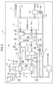
本発明の第1実施形態に係る燃料電池システム10は、図1に示すように、燃料電池スタック12、アノードガス系装置14及びカソードガス系装置16を備える。燃料電池スタック12は、アノードガス系装置14から供給されるアノードガス(水素等の燃料ガス)と、カソードガス系装置16から供給されるカソードガス(エア等の酸化剤ガス)とに基づき発電を行う。この燃料電池システム10は、例えば、燃料電池車両11(以下、単に車両11ともいう)の図示しないモータルーム等に搭載される。
[First Embodiment]
As shown in FIG. 1, the fuel cell system 10 according to the first embodiment of the present invention includes a fuel cell stack 12, an anode gas system device 14, and a cathode gas system device 16. The fuel cell stack 12 generates power based on the anode gas (fuel gas such as hydrogen) supplied from the anode gas system device 14 and the cathode gas (oxidizer gas such as air) supplied from the cathode gas system device 16. conduct. The fuel cell system 10 is mounted in, for example, a motor room of a fuel cell vehicle 11 (hereinafter, also simply referred to as a vehicle 11), which is not shown.

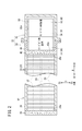
図2に示すように、燃料電池スタック12は、アノードガスとカソードガスの電気化学反応により発電を行う複数の発電セル18を有する。複数の発電セル18は、燃料電池スタック12を車両11に搭載した状態で、電極面を立位姿勢にして車長方向(紙面手前及び紙面奥方向:矢印A方向)に直交する車幅方向(矢印B方向)に沿って積層された積層体20に構成されている。なお、複数の発電セル18は、車長方向や重力方向(矢印C方向)に積層されていてもよい。 As shown in FIG. 2, the fuel cell stack 12 has a plurality of power generation cells 18 that generate power by an electrochemical reaction between an anode gas and a cathode gas. The plurality of power generation cells 18 have the fuel cell stack 12 mounted on the vehicle 11 and have the electrode surface in an upright position and are orthogonal to the vehicle length direction (front of the paper and back of the paper: arrow A direction) in the vehicle width direction (the direction of the arrow A). It is configured as a laminated body 20 laminated along the arrow B direction). The plurality of power generation cells 18 may be stacked in the vehicle length direction or the gravity direction (arrow C direction).

発電セル18は、図示しない電解質膜・電極構造体(以下、「MEA」という)と、MEAを挟持する図示しない2つのセパレータとで構成される。隣り合う発電セル18同士のセパレータは、その外周同士が溶接、ろう付け、かしめ等により接合され、一体的な接合セパレータに構成される。 The power generation cell 18 is composed of an electrolyte membrane / electrode structure (hereinafter referred to as “MEA”) (hereinafter, not shown) and two separators (hereinafter, not shown) that sandwich the MEA. The separators between adjacent power generation cells 18 are formed by joining the outer periphery thereof by welding, brazing, caulking, or the like to form an integral joining separator.

発電セル18のMEAは、電解質膜(例えば、固体高分子電解質膜(陽イオン交換膜))と、電解質膜の一方の面に設けられたアノード電極と、電解質膜の他方の面に設けられたカソード電極とを有する(共に不図示)。2つのセパレータは、MEAと対向し合う面の各々に、アノードガスを流通させるアノードガス流路と、カソードガスを流通させるカソードガス流路とを形成する。また、2つのセパレータ同士が対向し合う面には、冷却媒体を流通させる冷却媒体流路が形成される。アノードガス流路、カソードガス流路、冷却媒体流路は、各流体を矢印A方向に流通させる。 The MEA of the power generation cell 18 is provided on an electrolyte membrane (for example, a solid polymer electrolyte membrane (cation exchange membrane)), an anode electrode provided on one surface of the electrolyte membrane, and the other surface of the electrolyte membrane. It has a cathode electrode (both not shown). The two separators form an anode gas flow path through which the anode gas flows and a cathode gas flow path through which the cathode gas flows on each of the surfaces facing the MEA. Further, a cooling medium flow path through which the cooling medium flows is formed on the surface where the two separators face each other. The anode gas flow path, the cathode gas flow path, and the cooling medium flow path allow each fluid to flow in the direction of arrow A.

また、複数の発電セル18(積層体20)は、アノードガス、カソードガス及び冷却媒体を、発電セル18の積層方向(矢印B方向)に沿ってセパレータ面の各々に独立して流通させる複数の連通孔(アノードガス連通孔22、カソードガス連通孔24、冷却媒体連通孔26)を備える。積層体20内において、アノードガス連通孔22はアノードガス流路に連通し、カソードガス連通孔24はカソードガス流路に連通し、冷却媒体連通孔26は冷却媒体流路に連通している。 Further, the plurality of power generation cells 18 (laminated body 20) independently distribute the anode gas, the cathode gas and the cooling medium to each of the separator surfaces along the stacking direction (arrow B direction) of the power generation cells 18. A communication hole (anode gas communication hole 22, cathode gas communication hole 24, cooling medium communication hole 26) is provided. In the laminate 20, the anode gas communication hole 22 communicates with the anode gas flow path, the cathode gas communication hole 24 communicates with the cathode gas flow path, and the cooling medium communication hole 26 communicates with the cooling medium flow path.

燃料電池スタック12に供給されたアノードガスは、アノードガス連通孔22(アノード入口連通孔)を流通してアノードガス流路に流入する。アノード電極で発電に使用されたアノードオフガスは、アノードガス流路からアノードガス連通孔22(アノード出口連通孔)に流出して燃料電池スタック12の外部に排出される。 The anode gas supplied to the fuel cell stack 12 flows through the anode gas communication hole 22 (anode inlet communication hole) and flows into the anode gas flow path. The anode off gas used for power generation at the anode electrode flows out from the anode gas flow path to the anode gas communication hole 22 (anode outlet communication hole) and is discharged to the outside of the fuel cell stack 12.

燃料電池スタック12に供給されたカソードガスは、カソードガス連通孔24(カソード入口連通孔)を流通してカソードガス流路に流入する。カソード電極で発電に使用されたカソードオフガスは、カソードガス流路からカソードガス連通孔24(カソード出口連通孔)に流出して燃料電池スタック12の外部に排出される。 The cathode gas supplied to the fuel cell stack 12 flows through the cathode gas communication hole 24 (cathode inlet communication hole) and flows into the cathode gas flow path. The cathode off gas used for power generation at the cathode electrode flows out from the cathode gas flow path to the cathode gas communication hole 24 (cathode outlet communication hole) and is discharged to the outside of the fuel cell stack 12.

燃料電池スタック12に供給された冷却媒体は、冷却媒体連通孔26(冷却媒体入口連通孔)を流通して冷却媒体流路に流入される。発電セル18を冷却した冷却媒体は、冷却媒体流路から冷却媒体連通孔26(冷却媒体出口連通孔)に流出して燃料電池スタック12の外部に排出される。 The cooling medium supplied to the fuel cell stack 12 flows through the cooling medium communication hole 26 (cooling medium inlet communication hole) and flows into the cooling medium flow path. The cooling medium that has cooled the power generation cell 18 flows out from the cooling medium flow path to the cooling medium communication hole 26 (cooling medium outlet communication hole) and is discharged to the outside of the fuel cell stack 12.

さらに、本実施形態に係る燃料電池スタック12は、スタックケース28に積層体20を収容している。スタックケース28の発電セル18の積層方向(矢印B方向)の両側面には、スタックケース28の内部空間に連通する開孔28aが形成されている。 Further, in the fuel cell stack 12 according to the present embodiment, the laminated body 20 is housed in the stack case 28. Opening holes 28a communicating with the internal space of the stack case 28 are formed on both side surfaces of the power generation cells 18 of the stack case 28 in the stacking direction (direction of arrow B).

積層体20の矢印B方向の一端側(矢印Br側)には、図示しないターミナルプレート及び絶縁プレートが外方に向かって配置され、これらはスタックケース28内に収容される。スタックケース28の矢印Br側には、スタックケース28の開孔28aを閉塞するエンドプレート30が取り付けられる。エンドプレート30は、発電セル18の積層方向に締付荷重を付与する。 A terminal plate and an insulating plate (not shown) are arranged outward on one end side (arrow Br side) of the laminate 20 in the arrow B direction, and these are housed in the stack case 28. An end plate 30 that closes the opening 28a of the stack case 28 is attached to the arrow Br side of the stack case 28. The end plate 30 applies a tightening load in the stacking direction of the power generation cells 18.

積層体20の矢印B方向の他端側(矢印Bl側)には、図示しないターミナルプレート及び絶縁プレートが外方に向かって配置され、これらはスタックケース28内に収容される。そして、スタックケース28の矢印Bl側には、開孔28aを閉塞するように補機ケース32が取り付けられる。 A terminal plate and an insulating plate (not shown) are arranged outward on the other end side (arrow Bl side) of the laminate 20 in the arrow B direction, and these are housed in the stack case 28. Then, an auxiliary machine case 32 is attached to the arrow Bl side of the stack case 28 so as to close the opening 28a.

補機ケース32は、燃料電池システム10の補機34や配管36の一部を収容及び保護するための保護筐体であり、スタックケース28の矢印Bl側に固定される。補機ケース32は、スタックケース28に接合される凹形状の第1ケース部材38と、第1ケース部材38に接合される凹形状の第2ケース部材40とを備え、これらの部材の内部に、補機34を収納する収納空間32aを有する。 The auxiliary machine case 32 is a protective housing for accommodating and protecting a part of the auxiliary machine 34 and the pipe 36 of the fuel cell system 10, and is fixed to the arrow Bl side of the stack case 28. The auxiliary machine case 32 includes a concave first case member 38 joined to the stack case 28 and a concave second case member 40 joined to the first case member 38, and is inside these members. , Has a storage space 32a for accommodating the auxiliary machine 34.

第1ケース部材38は、ボルトによりスタックケース28に接合され、スタックケース28の内部空間と補機ケース32の収納空間32aとを区画する取付壁部42と、取付壁部42の外縁に連なると共に矢印Bl方向に突出する周壁44とを有する。取付壁部42は、発電セル18の積層体20に積層方向の締付荷重を付与するエンドプレートとしての機能を有している。取付壁部42には、発電セル18のアノードガス連通孔22、カソードガス連通孔24、冷却媒体連通孔26にそれぞれ連通して、流体の流通用の配管36を接続する孔部42aが設けられている。 The first case member 38 is joined to the stack case 28 by bolts, and is connected to the mounting wall portion 42 that separates the internal space of the stack case 28 and the storage space 32a of the auxiliary machine case 32 and the outer edge of the mounting wall portion 42. It has a peripheral wall 44 protruding in the direction of the arrow Bl. The mounting wall portion 42 has a function as an end plate that applies a tightening load in the stacking direction to the laminated body 20 of the power generation cell 18. The mounting wall portion 42 is provided with a hole portion 42a that communicates with the anode gas communication hole 22, the cathode gas communication hole 24, and the cooling medium communication hole 26 of the power generation cell 18 to connect the fluid flow pipe 36. ing.

また、補機ケース32内は、取付壁部42に隣接して主にアノードガス系装置14が設けられる第1空間46と、第1空間46に隣接して主にカソードガス系装置16が設けられる第2空間48とを有する。本実施形態に係る燃料電池システム10の配管構造50は、主にカソードガス系装置16に関わり、その一部が補機ケース32内の第2空間48に設けられると共に、他部が補機ケース32の外部に設けられる。 Further, in the auxiliary machine case 32, a first space 46 in which the anode gas system device 14 is mainly provided adjacent to the mounting wall portion 42 and a cathode gas system device 16 mainly provided adjacent to the first space 46 are provided. It has a second space 48 and the like. The piping structure 50 of the fuel cell system 10 according to the present embodiment is mainly related to the cathode gas system device 16, a part thereof is provided in the second space 48 in the auxiliary machine case 32, and the other part is the auxiliary machine case. It is provided outside the 32.

図1に戻り、次にカソードガス系装置16の全体構成について説明する。カソードガス系装置16は、配管構造50を構成する配管36として、外部のカソードガス(エア)を燃料電池スタック12に供給する供給管52と、燃料電池スタック12から外部にカソードオフガスを排出する排出管54とを有する。さらに、カソードガス系装置16は、供給管52と排出管54の間を接続し、供給管52を流通する水分を含むカソードガスを、燃料電池スタック12に通さずに排出管54に流通させるバイパス管56を有する。 Returning to FIG. 1, the overall configuration of the cathode gas system device 16 will be described next. The cathode gas system device 16 has a supply pipe 52 for supplying an external cathode gas (air) to the fuel cell stack 12 as a pipe 36 constituting the piping structure 50, and a discharge pipe for discharging the cathode off gas from the fuel cell stack 12 to the outside. It has a tube 54. Further, the cathode gas system device 16 connects between the supply pipe 52 and the discharge pipe 54, and allows the cathode gas containing water flowing through the supply pipe 52 to flow to the discharge pipe 54 without passing through the fuel cell stack 12. It has a tube 56.

カソードガス系装置16は、供給管52及び排出管54の途上に複数種類の補機34を備える。具体的には、カソードガス系装置16の供給系は、供給管52上のカソードガスの流通方向上流側から下流側に向かって順に、エアクリーナ58、エキスパンダ98に連結するコンプレッサ96(エキスパンダユニット60)、インタークーラ62、加湿器64、供給側気液分離装置66を備える。このため、供給管52は、エアクリーナ58とコンプレッサ96の間を接続する第1供給管68、コンプレッサ96とインタークーラ62の間を接続する第2供給管70、インタークーラ62と加湿器64の間を接続する第3供給管72、加湿器64と供給側気液分離装置66の間を接続する第4供給管74、及び供給側気液分離装置66と燃料電池スタック12の間を接続する第5供給管76を含んで構成される。 The cathode gas system device 16 includes a plurality of types of auxiliary equipment 34 in the middle of the supply pipe 52 and the discharge pipe 54. Specifically, the supply system of the cathode gas system device 16 is connected to the air cleaner 58 and the expander 98 in order from the upstream side to the downstream side in the flow direction of the cathode gas on the supply pipe 52 (expander unit). 60), an intercooler 62, a humidifier 64, and a supply-side gas-liquid separation device 66 are provided. Therefore, the supply pipe 52 is between the first supply pipe 68 connecting between the air cleaner 58 and the compressor 96, the second supply pipe 70 connecting between the compressor 96 and the intercooler 62, and between the intercooler 62 and the humidifier 64. A third supply pipe 72 for connecting, a fourth supply pipe 74 for connecting between the humidifier 64 and the supply-side air-liquid separator 66, and a second for connecting between the supply-side air-liquid separator 66 and the fuel cell stack 12. 5 Supply pipe 76 is included.

また、カソードガス系装置16の排出系は、排出管54上のカソードオフガスの流通方向上流側から下流側に向かって順に、前記加湿器64、排出側気液分離装置78、エキスパンダ98(エキスパンダユニット60)、希釈装置80を備える。このため、排出管54は、燃料電池スタック12と加湿器64の間を接続する第1排出管82、加湿器64と排出側気液分離装置78の間を接続する第2排出管84、排出側気液分離装置78とエキスパンダ98の間を接続する第3排出管86、及びエキスパンダ98と希釈装置80の間を接続する第4排出管88を含んで構成される。 Further, the discharge system of the cathode gas system device 16 includes the humidifier 64, the discharge side gas-liquid separator 78, and the expander 98 (extracts) in this order from the upstream side to the downstream side in the flow direction of the cathode off gas on the discharge pipe 54. A panda unit 60) and a diluting device 80 are provided. Therefore, the discharge pipe 54 includes a first discharge pipe 82 that connects between the fuel cell stack 12 and the humidifier 64, and a second discharge pipe 84 that connects between the humidifier 64 and the discharge side air-liquid separation device 78. It includes a third discharge pipe 86 connecting between the side air-liquid separation device 78 and the expander 98, and a fourth discharge pipe 88 connecting between the expander 98 and the diluting device 80.

エアクリーナ58は、図示しない除去フィルタを内部に有し、外部から取り込んだエアに含まれる異物(ゴミ、塵芥、水等)を取り除き、このエアを第1供給管68に流出する。 The air cleaner 58 has a removal filter (not shown) inside, removes foreign matter (dust, dust, water, etc.) contained in the air taken in from the outside, and discharges the air to the first supply pipe 68.

エキスパンダユニット60は、ステータ(不図示)及びロータ90を筐体92(図1も参照)内に有し、燃料電池システム10の電源(燃料電池スタック12、図示しないバッテリ)から供給される電力によりロータ90を回転させるモータ機構94を備える。ロータ90は、コンプレッサ96を構成する第1フィン96aを一端に有すると共に、エキスパンダ98を構成する第2フィン98aを他端に有する。また、筐体92は、第1及び第2供給管68、70が連通すると共に第1フィン96aを収容するコンプレッサ96の供給用空間と、第3及び第4排出管86、88が連通すると共に第2フィン98aを収容するエキスパンダ98の排出用空間とを独立して備える。図3に示すように、第3排出管86は、円筒状の筐体92の外周面側に接続され、第4排出管88は、円筒状の筐体92の一端側中心部に接続される。 The expander unit 60 has a stator (not shown) and a rotor 90 in a housing 92 (see also FIG. 1), and power is supplied from a power source of the fuel cell system 10 (fuel cell stack 12, battery (not shown)). A motor mechanism 94 for rotating the rotor 90 is provided. The rotor 90 has a first fin 96a constituting the compressor 96 at one end and a second fin 98a constituting the expander 98 at the other end. Further, in the housing 92, the first and second supply pipes 68 and 70 communicate with each other, and the supply space of the compressor 96 accommodating the first fin 96a and the third and fourth discharge pipes 86 and 88 communicate with each other. It is provided independently with a discharge space for the expander 98 that accommodates the second fin 98a. As shown in FIG. 3, the third discharge pipe 86 is connected to the outer peripheral surface side of the cylindrical housing 92, and the fourth discharge pipe 88 is connected to the central portion on one end side of the cylindrical housing 92. ..

エキスパンダユニット60は、図1に示すように、インバータ装置(Power Drive Unit:PDU60a)の電力供給に基づき、ロータ90の回転速度が調整される。カソードガス系装置16は、ロータ90(第1フィン96a)の回転により供給管52の第1供給管68からカソードガスを吸引して、第2供給管70に圧縮されたカソードガス(圧縮エア)を流出させる。 As shown in FIG. 1, the expander unit 60 adjusts the rotation speed of the rotor 90 based on the power supply of the inverter device (Power Drive Unit: PDU60a). The cathode gas system device 16 sucks cathode gas from the first supply pipe 68 of the supply pipe 52 by the rotation of the rotor 90 (first fin 96a), and the cathode gas (compressed air) compressed into the second supply pipe 70. To leak.

インタークーラ62は、第2供給管70を介してコンプレッサ96から流入されるカソードガスを冷却して、第3供給管72に流出させる。インタークーラ62は、空冷式と水冷式の一方又は両方を採ることができる。第3供給管72には、上述のバイパス管56の一端が接続される。 The intercooler 62 cools the cathode gas flowing from the compressor 96 through the second supply pipe 70 and causes it to flow out to the third supply pipe 72. The intercooler 62 can be either an air-cooled type or a water-cooled type, or both. One end of the above-mentioned bypass pipe 56 is connected to the third supply pipe 72.

加湿器64は、第3供給管72から供給されるカソードガスを、排出管54のカソードオフガスを利用して加湿する。すなわち、カソードオフガスには、燃料電池スタック12の発電で生じた水(生成水)が含まれており、加湿器64は、この水をカソードガスに適宜移動させて第4供給管74に流出させる。 The humidifier 64 humidifies the cathode gas supplied from the third supply pipe 72 by using the cathode off gas of the discharge pipe 54. That is, the cathode off gas contains water (generated water) generated by the power generation of the fuel cell stack 12, and the humidifier 64 appropriately moves this water to the cathode gas and causes it to flow out to the fourth supply pipe 74. ..

供給側気液分離装置66は、加湿されたカソードガスが供給され、カソードガスから水分を分離し適宜の湿潤状態として、第5供給管76にカソードガスを流出させる。第5供給管76は、燃料電池スタック12のカソードガス連通孔24に連通する孔部42a(図2参照)に接続され、カソードガスを燃料電池スタック12に供給する。 The supply-side gas-liquid separation device 66 is supplied with a humidified cathode gas, separates water from the cathode gas, puts it in an appropriate wet state, and causes the cathode gas to flow out to the fifth supply pipe 76. The fifth supply pipe 76 is connected to a hole 42a (see FIG. 2) communicating with the cathode gas communication hole 24 of the fuel cell stack 12, and supplies the cathode gas to the fuel cell stack 12.

また、燃料電池システム10は、アノードガス系装置14にアノードオフガスの流路を開閉するバルブ106を備える。すなわち、燃料電池システム10は、適宜のタイミングでバルブ106を開閉することで、アノードガス系装置14の気液分離装置14aに流入したアノードオフガス(水及び水素ガス)をカソードガス系装置16の排出系に排出する。 Further, the fuel cell system 10 includes a valve 106 for opening and closing the flow path of the anode off gas in the anode gas system device 14. That is, the fuel cell system 10 opens and closes the valve 106 at an appropriate timing to discharge the anode off gas (water and hydrogen gas) flowing into the gas-liquid separation device 14a of the anode gas system device 14 from the cathode gas system device 16. Discharge to the system.

さらに、供給側気液分離装置66には、排水管108が接続され、この排水管108は、所定経路を通って第4排出管88に接続されている。排水管108の途中位置には、排水する水の量を調整するオリフィス110が設けられている。 Further, a drain pipe 108 is connected to the supply-side gas-liquid separation device 66, and the drain pipe 108 is connected to the fourth discharge pipe 88 through a predetermined path. An orifice 110 for adjusting the amount of drained water is provided at an intermediate position of the drain pipe 108.

一方、カソードガス系装置16の第1排出管82には、上述したように、燃料電池スタック12の発電時に生じた生成水がカソードオフガスに含まれて排出される。このカソードオフガスは、第1排出管82から加湿器64に流入して供給側のカソードガスを加湿する。加湿器64の下流側に接続される第2排出管84には、加湿に利用されなかった水と共にカソードオフガスが流出される。 On the other hand, as described above, the cathode off gas contains the generated water generated during the power generation of the fuel cell stack 12 and is discharged to the first discharge pipe 82 of the cathode gas system device 16. This cathode off gas flows into the humidifier 64 from the first discharge pipe 82 to humidify the cathode gas on the supply side. The cathode off gas flows out to the second discharge pipe 84 connected to the downstream side of the humidifier 64 together with the water not used for humidification.

また、燃料電池システム10は、燃料電池スタック12の反応に伴い生成される生成水をカソードガス連通孔24から排出するため、スタックケース28と第4排出管88の間にドレン排出管100を設けている。このドレン排出管100の途中位置には、ドレン排出管100の流路を開閉するバルブ102が設けられる。さらに、第1排出管82の途中位置には、第1排出管82とドレン排出管100との間を接続する分岐管83が設けられている。すなわち、第1排出管82を流通する水の一部は、バルブ102の開状態で、加湿器64の上流側から分岐管83に流入して第4排出管88に排出される。 Further, in the fuel cell system 10, a drain discharge pipe 100 is provided between the stack case 28 and the fourth discharge pipe 88 in order to discharge the generated water generated by the reaction of the fuel cell stack 12 from the cathode gas communication hole 24. ing. A valve 102 for opening and closing the flow path of the drain discharge pipe 100 is provided at an intermediate position of the drain discharge pipe 100. Further, a branch pipe 83 connecting between the first discharge pipe 82 and the drain discharge pipe 100 is provided at an intermediate position of the first discharge pipe 82. That is, a part of the water flowing through the first discharge pipe 82 flows into the branch pipe 83 from the upstream side of the humidifier 64 in the open state of the valve 102 and is discharged to the fourth discharge pipe 88.

一方、加湿器64の下流側に接続される第2排出管84には、排出管54のカソードオフガスの圧力を調整する背圧弁112が設けられている。背圧弁112は、例えばバタフライバルブとして構成され、燃料電池スタック12に要求される発電電流値、図示しない圧力センサや流量センサで検出される圧力値や流量値に基づきその開度が制御される。 On the other hand, the second discharge pipe 84 connected to the downstream side of the humidifier 64 is provided with a back pressure valve 112 for adjusting the pressure of the cathode off gas of the discharge pipe 54. The back pressure valve 112 is configured as, for example, a butterfly valve, and its opening degree is controlled based on the power generation current value required for the fuel cell stack 12, the pressure value and the flow rate value detected by a pressure sensor or a flow rate sensor (not shown).

排出側気液分離装置78は、第2排出管84から流入されるカソードオフガスを、気体(主にエア)と液体(主に水)に分離して水分を除去することで、カソードオフガス中の水分濃度を低下させる。この排出側気液分離装置78には、第2及び第3排出管84、86の他に、排水管114が接続されている。排水管114は、エキスパンダユニット60から導出される第4排出管88に接続されている。また排水管114には、内部流路を開閉するバルブ116が設けられている。 The discharge side gas-liquid separation device 78 separates the cathode off gas flowing from the second discharge pipe 84 into a gas (mainly air) and a liquid (mainly water) to remove water, so that the cathode off gas is contained in the cathode off gas. Reduces water concentration. In addition to the second and third discharge pipes 84 and 86, a drain pipe 114 is connected to the discharge side gas-liquid separation device 78. The drain pipe 114 is connected to a fourth drain pipe 88 led out from the expander unit 60. Further, the drain pipe 114 is provided with a valve 116 for opening and closing the internal flow path.

排出側気液分離装置78は、気体に可及的に水を含まない状態として、この気体(カソードオフガス)を第3排出管86に流出させる。このため例えば、排出側気液分離装置78は、重力方向に適度な深さを有する筒体78aに形成されている(図3も参照)。第3排出管86は、このカソードオフガスをエキスパンダ98に流通させる。 The discharge-side gas-liquid separation device 78 causes the gas (cathode-off gas) to flow out to the third discharge pipe 86 in a state where the gas contains as little water as possible. Therefore, for example, the discharge-side gas-liquid separation device 78 is formed in a tubular body 78a having an appropriate depth in the direction of gravity (see also FIG. 3). The third discharge pipe 86 distributes this cathode off gas to the expander 98.

エキスパンダ98は、カソードオフガスにより第2フィン98aが回転することで、カソードオフガスの流体エネルギをコンプレッサ96に伝達する。すなわち流体エネルギの再生装置として機能する。またエキスパンダ98は、流体エネルギの回収に伴いカソードオフガスを膨張することでカソードオフガスの圧力を低下させ、このカソードオフガスを第4排出管88に流出させる。 The expander 98 transfers the fluid energy of the cathode off gas to the compressor 96 by rotating the second fin 98a by the cathode off gas. That is, it functions as a fluid energy regenerator. Further, the expander 98 reduces the pressure of the cathode off gas by expanding the cathode off gas with the recovery of the fluid energy, and causes the cathode off gas to flow out to the fourth discharge pipe 88.

第3排出管86の途中位置には、バイパス管56の他端が接続されている。バイパス管56には、管内を開閉するバイパス弁120が設けられる。バイパス弁120は、燃料電池システム10のECUの制御下に適宜開閉することで、供給管52のカソードガスを排出管54に流通させ、排出管54を介して排気する。 The other end of the bypass pipe 56 is connected to the middle position of the third discharge pipe 86. The bypass pipe 56 is provided with a bypass valve 120 that opens and closes the inside of the pipe. The bypass valve 120 appropriately opens and closes under the control of the ECU of the fuel cell system 10 to allow the cathode gas of the supply pipe 52 to flow through the discharge pipe 54 and exhaust the gas through the discharge pipe 54.

希釈装置80は、図示しないフィルタを内部に有し、第4排出管88を介して流通してきた気体及び液体が流入される。上述したように第4排出管88には、排水管108、114、及びドレン排出管100が接続されている。このため、希釈装置80は、水素を希釈しつつ、気体や液体をクリーンな状態として車両11の外部に排出する。 The diluting device 80 has a filter (not shown) inside, and the gas and liquid flowing through the fourth discharge pipe 88 flow into the diluting device 80. As described above, the drain pipes 108 and 114 and the drain discharge pipe 100 are connected to the fourth discharge pipe 88. Therefore, the diluting device 80 dilutes hydrogen and discharges the gas or liquid to the outside of the vehicle 11 in a clean state.

以上のように構成されるカソードガス系装置16は、カソードオフガスが流通する排出管54の上流側に多くの水が含まれる。ここで、エキスパンダ98を排出管54に接続した構成では、カソードオフガスの水が筐体92(排出側空間)内に多量に流入した場合、エキスパンダ98が動作不良となるおそれがある。また仮に、車両11の周囲の気温が低温(氷点下以下)となりエキスパンダ98に流入した水が凍結すると、エキスパンダ98が故障する可能性がある。 The cathode gas system device 16 configured as described above contains a large amount of water on the upstream side of the discharge pipe 54 through which the cathode off gas flows. Here, in the configuration in which the expander 98 is connected to the discharge pipe 54, if a large amount of water of the cathode off gas flows into the housing 92 (discharge side space), the expander 98 may malfunction. Further, if the temperature around the vehicle 11 becomes low (below freezing point) and the water flowing into the expander 98 freezes, the expander 98 may break down.

このため、燃料電池システム10の配管構造50では、車両11に搭載した状態(実際のシステム構成)において、エキスパンダ98に水が流入することを可及的に回避する構成としている。以下、図3を参照して、実際のシステム構成について詳述していく。なお以下では、図3(又は図2)の矢印表記に基づき各構成の位置及び方向を説明する。図示例の矢印A方向は車両11の前後方向であり、矢印Af方向は車両11の前方向に相当し、矢印Ar方向は車両11の後方向に相当する。図示例の矢印B方向は車両11の左右方向であり、矢印Bl方向は車両11の左方向に相当し、矢印Br方向は車両11の右方向に相当する。図示例の矢印C方向は車両11の上下方向(重力方向)であり、矢印Ctは車両11の上方向に相当し、矢印Cbは車両11の下方向に相当する。 Therefore, the piping structure 50 of the fuel cell system 10 is configured to prevent water from flowing into the expander 98 as much as possible when it is mounted on the vehicle 11 (actual system configuration). Hereinafter, the actual system configuration will be described in detail with reference to FIG. In the following, the position and direction of each configuration will be described based on the arrow notation in FIG. 3 (or FIG. 2). The arrow A direction in the illustrated example is the front-rear direction of the vehicle 11, the arrow Af direction corresponds to the front direction of the vehicle 11, and the arrow Ar direction corresponds to the rear direction of the vehicle 11. The arrow B direction in the illustrated example is the left-right direction of the vehicle 11, the arrow Bl direction corresponds to the left direction of the vehicle 11, and the arrow Br direction corresponds to the right direction of the vehicle 11. The arrow C direction in the illustrated example is the vertical direction (gravity direction) of the vehicle 11, the arrow Ct corresponds to the upward direction of the vehicle 11, and the arrow Cb corresponds to the downward direction of the vehicle 11.

図3は、補機ケース32の第1ケース部材38から第2ケース部材40を外した状態におけるカソードガス系装置16(燃料電池システム10)の配管構造50を示す側面図である。なお、カソードガス系装置16は、上述したようにアノードガス系装置14の外側隣接位置に設けられており(図2も参照)、図3中では図示は省略するが、カソードガス系装置16の奥側にアノードガス系装置14の補機34や配管36が部分的に設けられる。 FIG. 3 is a side view showing a piping structure 50 of the cathode gas system device 16 (fuel cell system 10) in a state where the second case member 40 is removed from the first case member 38 of the auxiliary machine case 32. As described above, the cathode gas system device 16 is provided at a position adjacent to the outside of the anode gas system device 14 (see also FIG. 2), and although not shown in FIG. 3, the cathode gas system device 16 is provided. Auxiliary equipment 34 and piping 36 of the anode gas system device 14 are partially provided on the back side.

実際のシステム構成において、燃料電池スタック12は、図示しないマウント構造によりモータルームに収納されている。エキスパンダユニット60は、燃料電池スタック12の重力方向下方(矢印Cb方向)で当該燃料電池スタック12から離間し、且つ燃料電池スタック12の矢印Af側と重なる位置に固定されている。エキスパンダユニット60の周囲には、エアクリーナ58及びインタークーラ62が配置されている。つまり、カソードガス系装置16の供給系上流側の補機34(エアクリーナ58、エキスパンダユニット60、インタークーラ62)は、補機ケース32の外部に設けられる。 In an actual system configuration, the fuel cell stack 12 is housed in a motor room by a mount structure (not shown). The expander unit 60 is fixed at a position that is separated from the fuel cell stack 12 below the gravity direction (arrow Cb direction) of the fuel cell stack 12 and overlaps with the arrow Af side of the fuel cell stack 12. An air cleaner 58 and an intercooler 62 are arranged around the expander unit 60. That is, the auxiliary equipment 34 (air cleaner 58, expander unit 60, intercooler 62) on the upstream side of the supply system of the cathode gas system device 16 is provided outside the auxiliary equipment case 32.

その一方で、カソードガス系装置16の加湿器64は、燃料電池スタック12の側方(補機ケース32内の上側)に設けられる。また、加湿器64の重力方向下方(矢印Cb方向)(補機ケース32内の下側)には、供給側気液分離装置66及び排出側気液分離装置78が設けられる。供給側気液分離装置66は、補機ケース32の矢印Ar側に配置され、排出側気液分離装置78は、補機ケース32の矢印Af側に配置される。つまり、カソードガス系装置16の加湿器64、2つの気液分離装置66、78は、補機ケース32内に収容される。 On the other hand, the humidifier 64 of the cathode gas system device 16 is provided on the side of the fuel cell stack 12 (upper side in the auxiliary machine case 32). Further, a supply-side gas-liquid separation device 66 and a discharge-side gas-liquid separation device 78 are provided below the humidifier 64 in the gravity direction (direction of arrow Cb) (lower side in the auxiliary machine case 32). The supply-side gas-liquid separation device 66 is arranged on the arrow Ar side of the auxiliary machine case 32, and the discharge-side gas-liquid separation device 78 is arranged on the arrow Af side of the auxiliary machine case 32. That is, the humidifier 64 of the cathode gas system device 16 and the two gas-liquid separation devices 66 and 78 are housed in the auxiliary machine case 32.

カソードガス系装置16の供給管52及び排出管54は、上記のように配置された各補機34を、図1に示す接続関係で連結する。具体的には、第1供給管68は、エアクリーナ58の上端部とエキスパンダユニット60の筐体92の矢印Af側との間を接続している。第2供給管70は、エキスパンダユニット60の上部とインタークーラ62の矢印Ar側との間を接続している。 The supply pipe 52 and the discharge pipe 54 of the cathode gas system device 16 connect the auxiliary machines 34 arranged as described above in the connection relationship shown in FIG. Specifically, the first supply pipe 68 connects the upper end portion of the air cleaner 58 and the arrow Af side of the housing 92 of the expander unit 60. The second supply pipe 70 is connected between the upper portion of the expander unit 60 and the arrow Ar side of the intercooler 62.

第3供給管72は、インタークーラ62の上部と加湿器64の矢印Af側との間を接続している。第3供給管72は、補機ケース32の外と内を貫通するように補機ケース32に固定されるコネクタ部材122を有する。このコネクタ部材122は、補機ケース32の外部においてバイパス管56が接続される分岐部122aを有するT型又はY型コネクタに構成されている。 The third supply pipe 72 connects the upper part of the intercooler 62 and the arrow Af side of the humidifier 64. The third supply pipe 72 has a connector member 122 fixed to the auxiliary machine case 32 so as to penetrate the outside and the inside of the auxiliary machine case 32. The connector member 122 is configured as a T-type or Y-type connector having a branch portion 122a to which the bypass pipe 56 is connected outside the auxiliary machine case 32.

第4供給管74は、加湿器64の矢印Ar側と、供給側気液分離装置66の上部との間を接続している。また、供給側気液分離装置66と燃料電池スタック12との間を接続する第5供給管76は、取付壁部42の孔部42aに接続される。 The fourth supply pipe 74 connects between the arrow Ar side of the humidifier 64 and the upper part of the gas-liquid separation device 66 on the supply side. Further, the fifth supply pipe 76 connecting between the supply-side gas-liquid separation device 66 and the fuel cell stack 12 is connected to the hole portion 42a of the mounting wall portion 42.

一方、第1排出管82は、燃料電池スタック12の矢印Af側且つ矢印C方向の中間部と、加湿器64の矢印Af側との間を接続している。第1排出管82から分岐する分岐管83は、矢印Ar方向に延在した後、下方に向かいドレン排出管100に接続されている。第2排出管84は、加湿器64の筒状側面の下側から下方に突出し、排出側気液分離装置78の上端部78bに接続されている。第2排出管84と排出側気液分離装置78の接続箇所に設けられた継手124の内部には、背圧弁112が設けられている。 On the other hand, the first discharge pipe 82 is connected between the arrow Af side and the intermediate portion in the arrow C direction of the fuel cell stack 12 and the arrow Af side of the humidifier 64. The branch pipe 83 branching from the first discharge pipe 82 extends in the direction of the arrow Ar and then faces downward and is connected to the drain discharge pipe 100. The second discharge pipe 84 projects downward from the lower side of the tubular side surface of the humidifier 64, and is connected to the upper end portion 78b of the discharge side gas-liquid separation device 78. A back pressure valve 112 is provided inside the joint 124 provided at the connection point between the second discharge pipe 84 and the discharge side gas-liquid separation device 78.

排出側気液分離装置78は、第2排出管84が接続される上端部78bから矢印C方向の下方に所定長さ延在する筒体78aに形成されている。筒体78aの下部には、カソードオフガスから分離した水が貯留される一方で、排出側気液分離装置78の上端部78bには、水から分離した気体が流通する。この上端部78bには、第3排出管86が接続されると共にバイパス管56が接続される。 The discharge-side gas-liquid separation device 78 is formed in a tubular body 78a extending downward in the direction of arrow C from the upper end portion 78b to which the second discharge pipe 84 is connected. Water separated from the cathode off gas is stored in the lower part of the cylinder 78a, while the gas separated from the water flows in the upper end 78b of the gas-liquid separation device 78 on the discharge side. A third discharge pipe 86 is connected and a bypass pipe 56 is connected to the upper end portion 78b.

バイパス管56は、コネクタ部材122から補機ケース32の外を矢印Cb方向に延在し補機ケース32の下部に固定されたバルブ付コネクタ部材126に接続される外管128と、補機ケース32内でバルブ付コネクタ部材126から上端部78bに向かう内管130とを有する。バルブ付コネクタ部材126の内部にはバイパス弁120が設けられている。 The bypass pipe 56 includes an outer pipe 128 extending from the connector member 122 to the outside of the auxiliary equipment case 32 in the direction of the arrow Cb and connected to the connector member 126 with a valve fixed to the lower part of the auxiliary equipment case 32, and the auxiliary equipment case. Within 32, there is an inner pipe 130 that goes from the connector member 126 with a valve to the upper end 78b. A bypass valve 120 is provided inside the connector member 126 with a valve.

第3排出管86は、上端部78bに固定されると共に補機ケース32に固定されるコネクタ部材134と、コネクタ部材134に接続され補機ケース32の外で矢印Cb方向に延びてエキスパンダユニット60に接続される外管136とを備える。外管136は、エキスパンダユニット60の筐体92の矢印Ar側に接続される。 The third discharge pipe 86 has a connector member 134 fixed to the upper end portion 78b and fixed to the auxiliary machine case 32, and an expander unit connected to the connector member 134 and extending in the arrow Cb direction outside the auxiliary machine case 32. It is provided with an outer tube 136 connected to 60. The outer tube 136 is connected to the arrow Ar side of the housing 92 of the expander unit 60.

そして、第4排出管88は、エキスパンダユニット60の矢印Ar側の端部から矢印Ar方向に向かって延在している。この第4排出管88は、エキスパンダユニット60の筐体92から斜め上方に向かって所定長さ延在し、第4排出管88に設定された曲部138に至る。そして、第4排出管88は、曲部138において湾曲し、矢印Ar方向且つ斜め下方に再び延在し、希釈装置80(図1参照)に接続されている。希釈装置80は、例えば、車両11の矢印Ar側に配置される。 The fourth discharge pipe 88 extends from the end of the expander unit 60 on the arrow Ar side toward the arrow Ar direction. The fourth discharge pipe 88 extends diagonally upward from the housing 92 of the expander unit 60 by a predetermined length and reaches the curved portion 138 set in the fourth discharge pipe 88. Then, the fourth discharge pipe 88 is curved at the curved portion 138, extends in the direction of the arrow Ar and diagonally downward again, and is connected to the diluting device 80 (see FIG. 1). The diluting device 80 is arranged, for example, on the arrow Ar side of the vehicle 11.

排出側気液分離装置78の排水管114は、補機ケース32に固定され、バルブ116を内部に有するバルブ付コネクタ部材140を介して、筒体78aの下端部に接続されている。この排水管114は、補機ケース32の外部に露出されて、モータルーム内を矢印Ar方向且つ斜め下方に緩やかに延在している。また、排水管114は、途中位置114aにおいて若干曲がり、下方に急角度となった後に第4排出管88の接続コネクタ142に接続されている。第4排出管88の接続コネクタ142は、第4排出管88の曲部138よりも矢印Ar方向(下流側)に向かって(エキスパンダユニット60から)離れた位置に設定されている。 The drain pipe 114 of the discharge-side gas-liquid separation device 78 is fixed to the auxiliary machine case 32 and is connected to the lower end portion of the tubular body 78a via a connector member 140 with a valve having a valve 116 inside. The drainage pipe 114 is exposed to the outside of the auxiliary machine case 32, and gently extends in the motor room in the direction of the arrow Ar and diagonally downward. Further, the drainage pipe 114 is slightly bent at the intermediate position 114a and is connected to the connection connector 142 of the fourth discharge pipe 88 after making a steep downward angle. The connector 142 of the fourth discharge pipe 88 is set at a position (from the expander unit 60) toward the arrow Ar direction (downstream side) from the curved portion 138 of the fourth discharge pipe 88.

さらに、供給側気液分離装置66の排水管108は、補機ケース32に取り付けられるオリフィス付コネクタ部材144を介して、供給側気液分離装置66の下端部に接続されている。排水管108は、補機ケース32の外部に露出されて下方に向かって延在し、第4排出管88の接続コネクタ142に接続されている。またドレン排出管100は、燃料電池スタック12の矢印Cb側の孔部42aから突出し、バルブ102を有するバルブ付コネクタ部材146を介して下方に延在し、接続コネクタ142に接続されている。例えば、接続コネクタ142は、メインの配管36(第4排出管88)に対し2つの配管36(排水管108、排水管114)を接続可能な分岐部を有するマニホールドに構成されているとよい。 Further, the drain pipe 108 of the supply-side gas-liquid separation device 66 is connected to the lower end of the supply-side gas-liquid separation device 66 via a connector member 144 with an orifice attached to the auxiliary machine case 32. The drainage pipe 108 is exposed to the outside of the auxiliary machine case 32 and extends downward, and is connected to the connection connector 142 of the fourth drainage pipe 88. Further, the drain discharge pipe 100 protrudes from the hole 42a on the arrow Cb side of the fuel cell stack 12, extends downward via the valved connector member 146 having the valve 102, and is connected to the connection connector 142. For example, the connection connector 142 may be configured in a manifold having a branch portion capable of connecting two pipes 36 (drainage pipe 108, drainage pipe 114) to the main pipe 36 (fourth discharge pipe 88).

本実施形態に係る燃料電池システム10の配管構造50は、基本的には以上のように構成され、以下、その作用について説明する。 The piping structure 50 of the fuel cell system 10 according to the present embodiment is basically configured as described above, and its operation will be described below.

図1に示すように、燃料電池システム10は、通常の運転時(燃料電池スタック12の発電時)に、アノードガス系装置14により燃料電池スタック12にアノードガスを供給すると共に、燃料電池スタック12からアノードオフガスを排出する。また燃料電池システム10は、燃料電池スタック12の発電時に、カソードガス系装置16によりカソードガスを燃料電池スタック12に供給すると共に、燃料電池スタック12からカソードオフガスを排出する。 As shown in FIG. 1, the fuel cell system 10 supplies an anode gas to the fuel cell stack 12 by the anodic gas system device 14 during normal operation (during power generation of the fuel cell stack 12), and the fuel cell stack 12 Discharge the anode off gas from. Further, the fuel cell system 10 supplies the cathode gas to the fuel cell stack 12 by the cathode gas system device 16 at the time of power generation of the fuel cell stack 12, and discharges the cathode off gas from the fuel cell stack 12.

詳細には、図1及び図4に示すように、カソードガス系装置16は、エアクリーナ58を介して第1供給管68にカソードガスを流入させる。このカソードガスは、コンプレッサ96の駆動に基づき加圧され、第2供給管70、インタークーラ62及び第3供給管72を介して加湿器64に供給される。そしてカソードガスは、加湿器64において加湿されると、第4供給管74、供給側気液分離装置66、第5供給管76を介して燃料電池スタック12に供給される。 Specifically, as shown in FIGS. 1 and 4, the cathode gas system device 16 causes the cathode gas to flow into the first supply pipe 68 via the air cleaner 58. This cathode gas is pressurized based on the drive of the compressor 96, and is supplied to the humidifier 64 via the second supply pipe 70, the intercooler 62, and the third supply pipe 72. When the cathode gas is humidified in the humidifier 64, the cathode gas is supplied to the fuel cell stack 12 via the fourth supply pipe 74, the supply-side gas-liquid separation device 66, and the fifth supply pipe 76.

カソードガスは、燃料電池スタック12の発電により使用されることで、水を多量に含むカソードオフガスとなる。このカソードオフガスは、燃料電池スタック12から第1排出管82に排出される。そしてカソードオフガスは、第1排出管82から加湿器64に流入すると、保有する水分により供給するカソードガスを加湿する一方で、残った水分を含んだまま第2排出管84に排出される。 The cathode gas is used by the power generation of the fuel cell stack 12 to become a cathode off gas containing a large amount of water. This cathode off gas is discharged from the fuel cell stack 12 to the first discharge pipe 82. When the cathode off gas flows into the humidifier 64 from the first discharge pipe 82, the cathode gas supplied by the retained water is humidified, and the cathode off gas is discharged to the second discharge pipe 84 while containing the remaining water.

さらに、カソードオフガスは、第2排出管84から排出側気液分離装置78に流入して、排出側気液分離装置78により気体と液体(液水)に分離される。排出側気液分離装置78により液水が分離されたカソードオフガスは、排出側気液分離装置78の上端部78bに接続された第3排出管86を介してエキスパンダ98に流通する。排出側気液分離装置78の下流側に流出したカソードオフガスに含まれる液水は少ない。よって、エキスパンダ98は、液水が流入することによる動作不良が抑制され、良好な運転状態を維持し続けることができる。 Further, the cathode off gas flows into the discharge side gas-liquid separation device 78 from the second discharge pipe 84, and is separated into a gas and a liquid (liquid water) by the discharge side gas-liquid separation device 78. The cathode off gas from which the liquid water is separated by the discharge side gas-liquid separation device 78 flows to the expander 98 via the third discharge pipe 86 connected to the upper end portion 78b of the discharge side gas-liquid separation device 78. The amount of liquid water contained in the cathode off gas flowing out to the downstream side of the discharge-side gas-liquid separator 78 is small. Therefore, the expander 98 can be prevented from malfunctioning due to the inflow of liquid water, and can continue to maintain a good operating state.

また、排出側気液分離装置78は、カソードオフガスから分離した液水を、筒体78aの下端部に接続された排水管114を介して流出させる。ここで排水管114は、排出側気液分離装置78から矢印Ar方向(エキスパンダ98から離間する方向)且つ斜め下方に傾斜している。このため、液水は、その自重により、排水管114の傾斜に沿って滞留することなく流通することができ、第4排出管88の接続コネクタ142においてカソードオフガスに合流する。また図5に示すように、液水は、車両11の前進時における加速度を受けることで、矢印Ar方向に延在する排水管114内で矢印Ar側にスムーズに移動して、第4排出管88に合流する。従って、排出側気液分離装置78から液水を良好に排出することができる。 Further, the discharge-side gas-liquid separation device 78 causes the liquid water separated from the cathode off gas to flow out through the drain pipe 114 connected to the lower end portion of the tubular body 78a. Here, the drain pipe 114 is inclined diagonally downward in the direction of arrow Ar (direction away from the expander 98) from the discharge-side gas-liquid separation device 78. Therefore, the liquid water can flow along the inclination of the drain pipe 114 without staying due to its own weight, and joins the cathode off gas at the connection connector 142 of the fourth discharge pipe 88. Further, as shown in FIG. 5, the liquid water receives the acceleration when the vehicle 11 moves forward, and smoothly moves toward the arrow Ar side in the drainage pipe 114 extending in the arrow Ar direction, and is the fourth discharge pipe. Join 88. Therefore, the liquid water can be satisfactorily discharged from the gas-liquid separation device 78 on the discharge side.

第4排出管88は、エキスパンダ98から矢印Ar方向且つ斜め上方に一旦延在した後に、曲部138から矢印Ar方向且つ斜め下方に延在している。排水管114を通して第4排出管88に流入する液水は、曲部138よりも後方の接続コネクタ142から合流することで、エキスパンダ98側への逆流が防止される。なお、第4排出管88の接続コネクタ142には、上述したように排水管108を介して供給側気液分離装置66の液水や水素(アノードオフガス)も流入される。この液水についてもエキスパンダ98側に逆流することを防止することができる。そして、第4排出管88は、接続コネクタ142よりも後方の排出経路を通して、カソードオフガス(エア)、水、アノードオフガス(水素)を流通させ、さらに希釈装置80を介してこれらを車両11の外部に排出する。 The fourth discharge pipe 88 extends from the expander 98 in the direction of arrow Ar and diagonally upward, and then extends from the curved portion 138 in the direction of arrow Ar and diagonally downward. The liquid water flowing into the fourth discharge pipe 88 through the drain pipe 114 joins from the connection connector 142 behind the curved portion 138 to prevent backflow to the expander 98 side. As described above, the liquid water and hydrogen (anode off gas) of the supply-side gas-liquid separation device 66 also flow into the connection connector 142 of the fourth discharge pipe 88 via the drain pipe 108. This liquid water can also be prevented from flowing back to the expander 98 side. Then, the fourth discharge pipe 88 circulates the cathode off gas (air), water, and the anode off gas (hydrogen) through the discharge path behind the connector 142, and further, these are circulated to the outside of the vehicle 11 via the diluting device 80. Discharge to.

〔第2実施形態〕
次に、本発明の第2実施形態に係る燃料電池システム10Aについて説明する。なお、以降の説明において、燃料電池システム10と同一の構成又は同一の機能を有する構成には、同一の符号を付与してその詳細な説明は省略する。
[Second Embodiment]
Next, the fuel cell system 10A according to the second embodiment of the present invention will be described. In the following description, the same reference numerals are given to the configurations having the same configuration or the same functions as those of the fuel cell system 10, and detailed description thereof will be omitted.

図6に示すように、燃料電池システム10Aは、供給管52(第3供給管72)の途中位置に供給側バルブ150を備える点で、上記の燃料電池システム10と異なる。供給側バルブ150は、図示しないECUの制御下に開閉操作がなされることで、供給管52から燃料電池スタック12へのカソードガスの供給又は供給停止を行う。 As shown in FIG. 6, the fuel cell system 10A differs from the above fuel cell system 10 in that the supply side valve 150 is provided at an intermediate position of the supply pipe 52 (third supply pipe 72). The supply-side valve 150 is opened and closed under the control of an ECU (not shown) to supply or stop the supply of cathode gas from the supply pipe 52 to the fuel cell stack 12.

また、燃料電池システム10Aは、水が流通する箇所(ドレン排出管100、アノードガス系装置14の排水管108)のバルブ102、バルブ106にヒータ102a、106aを備える。ヒータ102a、106aは、低温環境下でバルブ102、106を加熱することにより、水の凍結によるバルブ102、106の動作不良(閉塞等)を回避する。 Further, the fuel cell system 10A includes heaters 102a and 106a at valves 102 and valves 106 at locations where water flows (drain discharge pipe 100, drain pipe 108 of the anode gas system device 14). The heaters 102a and 106a heat the valves 102 and 106 in a low temperature environment to avoid malfunction (blockage, etc.) of the valves 102 and 106 due to freezing of water.

さらに、燃料電池システム10Aは、図7に示すように、第3供給管72とバイパス管56の分岐部分を構成するユニット構造体152を備える。ユニット構造体152は、補機ケース32の外側に設けられる外側固定マニホールド154と、外側固定マニホールド154に連結されると共に補機ケース32の内側に収容されるバルブユニット156とを含む。 Further, as shown in FIG. 7, the fuel cell system 10A includes a unit structure 152 constituting a branch portion of the third supply pipe 72 and the bypass pipe 56. The unit structure 152 includes an outer fixed manifold 154 provided on the outside of the auxiliary machine case 32 and a valve unit 156 connected to the outer fixed manifold 154 and housed inside the auxiliary machine case 32.

外側固定マニホールド154は、その上端部154aに第3供給管72の可撓管が接続される。外側固定マニホールド154は、上端部154aから矢印Ar方向に延在する第1管部154bと、上端部154aから下方に短く延在した後矢印Ar方向に延在する第2管部154cとを備える。 The flexible pipe of the third supply pipe 72 is connected to the upper end portion 154a of the outer fixed manifold 154. The outer fixed manifold 154 includes a first pipe portion 154b extending in the arrow Ar direction from the upper end portion 154a, and a second pipe portion 154c extending downward from the upper end portion 154a in the arrow Ar direction. ..

バルブユニット156は、矢印A方向に短く延在して第1管部154bが接続される第1筒部156aと、同じく矢印A方向に短く延在して第2管部154cが接続される第2筒部156bとを有する。第1筒部156aと第2筒部156bは矢印C方向に並んで相互に連結されている。そして、第1筒部156aの内部には供給側バルブ150が設けられ、第2筒部156bの内部にはバイパス弁120が設けられている。 The valve unit 156 has a first tubular portion 156a extending shortly in the direction of arrow A to which the first pipe portion 154b is connected, and a second valve unit 156 extending shortly in the direction of arrow A to connect the second pipe portion 154c. It has two tubular portions 156b. The first cylinder portion 156a and the second cylinder portion 156b are arranged side by side in the direction of arrow C and are connected to each other. A supply-side valve 150 is provided inside the first cylinder portion 156a, and a bypass valve 120 is provided inside the second cylinder portion 156b.

第1筒部156aは、バルブユニット156の矢印Ar方向に設けられた加湿器64に接続される一方で、第2筒部156bは、矢印A方向後方に設けられた排出側気液分離装置158に接続される。すなわち、カソードガスは、インタークーラ62の下流において第3供給管72を流通すると、供給側バルブ150の開状態で、第1管部154b、第1筒部156aを流通して加湿器64に流入する。またカソードガスは、バイパス弁120の開状態で、第2管部154c、第2筒部156bを流通して排出側気液分離装置158に流入する。 The first cylinder portion 156a is connected to the humidifier 64 provided in the direction of the arrow Ar of the valve unit 156, while the second cylinder portion 156b is connected to the discharge side gas-liquid separation device 158 provided in the rear in the arrow A direction. Connected to. That is, when the cathode gas flows through the third supply pipe 72 downstream of the intercooler 62, the cathode gas flows through the first pipe portion 154b and the first cylinder portion 156a in the open state of the supply side valve 150 and flows into the humidifier 64. do. Further, the cathode gas flows through the second pipe portion 154c and the second cylinder portion 156b in the open state of the bypass valve 120 and flows into the gas-liquid separation device 158 on the discharge side.

排出側気液分離装置158は、補機ケース32内において加湿器64よりも矢印Cb方向に配置され、且つ矢印A方向に延在している。排出側気液分離装置158は、上記の第2筒部156bに接続される供給系ポート158aと、加湿器64の下流側に設けられる第2排出管84に接続される排出系ポート158bとを有する。排出系ポート158bは、加湿器64の下部に連通し内部に背圧弁112が設けられた継手124に接続されている。 The discharge-side gas-liquid separation device 158 is arranged in the auxiliary machine case 32 in the direction of arrow Cb with respect to the humidifier 64, and extends in the direction of arrow A. The discharge-side gas-liquid separator 158 has a supply system port 158a connected to the second cylinder portion 156b and a discharge system port 158b connected to a second discharge pipe 84 provided on the downstream side of the humidifier 64. Have. The discharge system port 158b communicates with the lower part of the humidifier 64 and is connected to a joint 124 provided with a back pressure valve 112 inside.

排出側気液分離装置158は、矢印A方向に延在する内部の空間内で第2排出管84のカソードオフガスを気体と液体に分離して水分を除去することで、カソードオフガス中の水分濃度を低下させる。そして排出側気液分離装置158の矢印Ar側の端部には、気体(空気、水素等)を流出させる気体流出ポート158cと、分離した液体(液水)を流出させる液体流出ポート158dとが設けられている。 The discharge side gas-liquid separation device 158 separates the cathode off gas of the second discharge pipe 84 into a gas and a liquid in the internal space extending in the direction of arrow A to remove water, thereby removing the water concentration in the cathode off gas. To reduce. At the end of the discharge side gas-liquid separation device 158 on the arrow Ar side, there are a gas outflow port 158c that allows gas (air, hydrogen, etc.) to flow out, and a liquid outflow port 158d that allows the separated liquid (liquid water) to flow out. It is provided.

気体流出ポート158cは、排出側気液分離装置158の本体部分から上方に突出し、また第3排出管86の一端が接続される固定コネクタ160が設けられている。第3排出管86は、排出側気液分離装置158から下方に延在し、その他端がエキスパンダ98に接続される。つまり、排出側気液分離装置158は、上方に突出する気体流出ポート158cから第3排出管86に気体を流出することで、カソードオフガスの水分(液水)を除去することができる。 The gas outflow port 158c projects upward from the main body portion of the discharge-side gas-liquid separation device 158, and is provided with a fixed connector 160 to which one end of the third discharge pipe 86 is connected. The third discharge pipe 86 extends downward from the discharge side gas-liquid separator 158, and the other end is connected to the expander 98. That is, the discharge side gas-liquid separation device 158 can remove the water content (liquid water) of the cathode off gas by flowing out the gas from the gas outflow port 158c projecting upward to the third discharge pipe 86.

液体流出ポート158dは、排出側気液分離装置158の矢印Ar側に設けられ、バルブ116を介して排水用コネクタ162に接続されている。排水用コネクタ162は、補機ケース32の外側且つ下方に突出して排水管114が接続される。また、排水用コネクタ162には、供給側気液分離装置66につながる排水管108と、分岐管83がつながるドレン排出管100とが接続されている。 The liquid outflow port 158d is provided on the arrow Ar side of the discharge-side gas-liquid separation device 158, and is connected to the drainage connector 162 via a valve 116. The drainage connector 162 projects outward and downward of the auxiliary machine case 32, and the drainage pipe 114 is connected to the drainage connector 162. Further, the drainage connector 162 is connected to a drainage pipe 108 connected to the supply-side gas-liquid separation device 66 and a drain discharge pipe 100 to which the branch pipe 83 is connected.

排水管114は、排水用コネクタ162の下端に連結される硬質配管(樹脂配管、金属配管)164により構成されている。硬質配管164(排水管114)は、排水用コネクタ162の接続箇所から矢印Ar方向且つ下方に緩やかに傾斜して延在している。硬質配管164が斜め下方に延在している途中位置には、矢印Bl側(図2参照:車幅方向)に第4排出管88が接続される接続コネクタ164aが設けられている。第4排出管88は、エキスパンダ98から矢印Ar方向且つ上方(矢印Ct方向)に傾斜して延在し、また接続コネクタ164aよりも若干上方に位置する曲部138を経由して、矢印Ar方向且つ下方に延在して接続コネクタ164aに接続されている。 The drainage pipe 114 is composed of a hard pipe (resin pipe, metal pipe) 164 connected to the lower end of the drainage connector 162. The rigid pipe 164 (drainage pipe 114) extends from the connection point of the drainage connector 162 in the direction of the arrow Ar and gently inclined downward. A connector 164a to which the fourth discharge pipe 88 is connected is provided on the side of the arrow Bl (see FIG. 2: in the vehicle width direction) at an intermediate position where the rigid pipe 164 extends diagonally downward. The fourth discharge pipe 88 extends from the expander 98 in the direction of the arrow Ar and inclined upward (in the direction of the arrow Ct), and passes through the curved portion 138 located slightly above the connector 164a, and the arrow Ar extends. It extends directionally and downwardly and is connected to the connector 164a.

第2実施形態に係る燃料電池システム10Aは、基本的には以上のように構成され、以下その作用効果について説明する。燃料電池システム10Aのカソードガス系装置16では、コンプレッサ96の駆動に基づきカソードガスを加圧することで、カソードガスが第3供給管72を矢印Ct方向に流通してユニット構造体152内に流入する。ユニット構造体152では、供給側バルブ150が開放している場合に、第1管部154b、第1筒部156aを介してカソードガスを加湿器64に供給する。カソードガスは、加湿器64にて加湿されると、加湿器64から供給側気液分離装置66等を介して燃料電池スタック12に供給される。 The fuel cell system 10A according to the second embodiment is basically configured as described above, and its operation and effect will be described below. In the cathode gas system device 16 of the fuel cell system 10A, by pressurizing the cathode gas based on the drive of the compressor 96, the cathode gas flows through the third supply pipe 72 in the direction of arrow Ct and flows into the unit structure 152. .. In the unit structure 152, when the supply-side valve 150 is open, the cathode gas is supplied to the humidifier 64 via the first pipe portion 154b and the first cylinder portion 156a. When the cathode gas is humidified by the humidifier 64, the cathode gas is supplied from the humidifier 64 to the fuel cell stack 12 via the supply-side air-liquid separator 66 and the like.

燃料電池スタック12の発電により使用されたカソードオフガスは、第1排出管82を介して加湿器64に流入する。加湿器64においてカソードオフガスは、保有する水分により供給するカソードガスを加湿する一方で、残った水分を含んだまま排出され、さらに排出系ポート158bを介して排出側気液分離装置158に流入する。 The cathode off gas used by the power generation of the fuel cell stack 12 flows into the humidifier 64 through the first discharge pipe 82. In the humidifier 64, the cathode off gas humidifies the cathode gas supplied by the retained water, and is discharged while containing the remaining water, and further flows into the discharge side gas-liquid separation device 158 via the discharge system port 158b. ..

また、ユニット構造体152においてバイパス弁120が開放している場合には、第2管部154c、第2筒部156b、供給系ポート158aを介して排出側気液分離装置158にカソードガスが供給される。排出側気液分離装置158では、カソードガス又はカソードオフガスが矢印Ar方向に移動し、この移動時に気体と液水を分離する。そして、気体は、排出側気液分離装置158の上部の気体流出ポート158c、固定コネクタ160を介して流出し、第3排出管86に沿って矢印Cb方向のエキスパンダ98に向かう。この気体に含まれる液水は少ないので、エキスパンダ98は、液水が流入することによる動作不良が抑制され、良好な運転状態を維持し続けることができる。 When the bypass valve 120 is open in the unit structure 152, the cathode gas is supplied to the discharge side gas-liquid separation device 158 via the second pipe portion 154c, the second cylinder portion 156b, and the supply system port 158a. Will be done. In the discharge side gas-liquid separation device 158, the cathode gas or the cathode off gas moves in the direction of the arrow Ar, and during this movement, the gas and the liquid water are separated. Then, the gas flows out through the gas outflow port 158c at the upper part of the discharge side gas-liquid separation device 158 and the fixed connector 160, and goes toward the expander 98 in the arrow Cb direction along the third discharge pipe 86. Since the amount of liquid water contained in this gas is small, the expander 98 can suppress malfunction due to the inflow of liquid water and can continue to maintain a good operating state.

一方、排出側気液分離装置158の液水は、装置後部の液体流出ポート158dを介して排水用コネクタ162に流入し、排水用コネクタ162から硬質配管164に流出する。硬質配管164は、傾斜角度が固定されている(可撓性を有していない)ことで液水をスムーズに流出させる。そして液水は、硬質配管164を流通する途中の接続コネクタ164aにおいて、エキスパンダ98から排出される気体と合流する。 On the other hand, the liquid water of the discharge side gas-liquid separation device 158 flows into the drainage connector 162 through the liquid outflow port 158d at the rear of the device, and flows out from the drainage connector 162 to the hard pipe 164. The rigid pipe 164 has a fixed inclination angle (does not have flexibility), so that liquid water can flow out smoothly. Then, the liquid water merges with the gas discharged from the expander 98 at the connector 164a in the middle of flowing through the hard pipe 164.

ここで、エキスパンダ98から延在する第4排出管88は、矢印A方向後方且つ矢印Ct方向に斜めに延在し、曲部138を経由して硬質配管164の接続コネクタ164aに接続されている。カソードオフガスから分離した液水は、その自重により硬質配管164内を斜め下方に傾斜して流通しており、第4排出管88に液体が向かうこと(つまりエキスパンダ98側への逆流)が防止される。 Here, the fourth discharge pipe 88 extending from the expander 98 extends rearward in the direction of arrow A and diagonally in the direction of arrow Ct, and is connected to the connection connector 164a of the hard pipe 164 via the curved portion 138. There is. The liquid water separated from the cathode off gas circulates diagonally downward in the hard pipe 164 due to its own weight, and prevents the liquid from heading to the fourth discharge pipe 88 (that is, backflow to the expander 98 side). Will be done.

本発明に係る燃料電池システム10は、以下の効果を奏する。 The fuel cell system 10 according to the present invention has the following effects.

燃料電池システム10、10Aは、気液分離装置(排出側気液分離装置78、158)の排水管114がエキスパンダ98よりも下流側の排出管54の接続部(接続コネクタ142、164a)に接続され、且つ排出側気液分離装置78、158から接続コネクタ142、164aに向かってエキスパンダ98から離間する方向へ斜め下方に延在していることで、エキスパンダ98に水が流入するのを抑制することができる。すなわち、排出側気液分離装置78、158は、エキスパンダ98の上方において、カソードオフガスから分離した水を、斜め下方に傾斜する排水管114を通じてエキスパンダ98の下流側の排出管54(第4排出管88)に安定的に流入させる。第4排出管88には、エキスパンダ98からカソードオフガスが流通しており、排水管114から第4排出管88に流通した水は逆流することなく排出管54の下流側に流出する。よって、燃料電池システム10、10Aは、水を殆ど含まないカソードオフガスを排出側気液分離装置78、158からエキスパンダ98に流入させ、エキスパンダ98を安定的に動作させることができる。これにより、エキスパンダ98の耐久性を大幅に高めることができ、また凍結等による損傷を抑制することができる。 In the fuel cell systems 10 and 10A, the drain pipe 114 of the gas-liquid separation device (discharge side gas-liquid separation device 78, 158) is connected to the connection portion (connection connector 142, 164a) of the discharge pipe 54 on the downstream side of the expander 98. Water flows into the expander 98 because it is connected and extends diagonally downward from the discharge side gas-liquid separator 78, 158 toward the connection connector 142, 164a in a direction away from the expander 98. Can be suppressed. That is, the discharge-side gas-liquid separation device 78, 158 is a discharge pipe 54 (fourth) on the downstream side of the expander 98, through a drain pipe 114 that inclines diagonally downward, to allow water separated from the cathode off gas above the expander 98. Stable inflow into the discharge pipe 88). The cathode off gas flows from the expander 98 to the fourth discharge pipe 88, and the water flowing from the drain pipe 114 to the fourth discharge pipe 88 flows out to the downstream side of the discharge pipe 54 without flowing back. Therefore, in the fuel cell systems 10 and 10A, the cathode off gas containing almost no water can flow into the expander 98 from the discharge side gas-liquid separation device 78 and 158, and the expander 98 can be operated stably. As a result, the durability of the expander 98 can be significantly improved, and damage due to freezing or the like can be suppressed.

また、エキスパンダ98と排出側気液分離装置78、158の間の排出管54(第3排出管86)は、排出側気液分離装置78の上端部78b(気体流出ポート158c)に接続されていることが好ましい。これにより、排出側気液分離装置78、158は、水の自重に基づきカソードオフガスから分離した水を装置内の下部側に貯留するので、より確実に水を含まないカソードオフガスを排出管54に流出することができる。 Further, the discharge pipe 54 (third discharge pipe 86) between the expander 98 and the discharge side gas-liquid separation device 78 and 158 is connected to the upper end portion 78b (gas outflow port 158c) of the discharge side gas-liquid separation device 78. Is preferable. As a result, the discharge-side gas-liquid separation device 78, 158 stores the water separated from the cathode off-gas based on its own weight in the lower part of the device, so that the cathode-off gas containing no water is more reliably discharged to the discharge pipe 54. Can be leaked.

また、供給管52と排出管54の間には、供給管52から排出管54にカソードガスを流通可能なバイパス管56が設けられ、バイパス管56は、排出側気液分離装置78、158に接続されているとよい。これにより、燃料電池システム10(カソードガス系装置16)は、バイパスしたカソードガスが排出側気液分離装置78、158を通過することで、エキスパンダ98に流通する気体の水分を大幅に低下させることができる。 Further, a bypass pipe 56 capable of flowing cathode gas from the supply pipe 52 to the discharge pipe 54 is provided between the supply pipe 52 and the discharge pipe 54, and the bypass pipe 56 is connected to the discharge side gas-liquid separation device 78 and 158. It should be connected. As a result, the fuel cell system 10 (cathode gas system device 16) significantly reduces the water content of the gas flowing through the expander 98 by allowing the bypassed cathode gas to pass through the discharge side gas-liquid separation devices 78 and 158. be able to.

また、供給管52とバイパス管56が接続される部分は、ユニット構造体152として構成され、ユニット構造体152は、供給管52としてカソードガスを燃料電池スタック12に向かわせる部分と、バイパス管56として気液分離装置158に連通する部分とを有する。このようにユニット構造体152を有することで、燃料電池システム10Aは、供給管52の分岐箇所がより簡単な構成となり、しかも排出側気液分離装置158にカソードガスを流通させる構造となる。よって、部品点数が削減され、作業効率を一層高めることができる。 Further, the portion where the supply pipe 52 and the bypass pipe 56 are connected is configured as a unit structure 152, and the unit structure 152 includes a portion where the cathode gas is directed to the fuel cell stack 12 as the supply pipe 52 and the bypass pipe 56. It has a portion that communicates with the gas-liquid separation device 158. By having the unit structure 152 in this way, the fuel cell system 10A has a structure in which the branching point of the supply pipe 52 has a simpler structure, and the cathode gas is circulated to the discharge side gas-liquid separation device 158. Therefore, the number of parts can be reduced and the work efficiency can be further improved.

また、燃料電池スタック12とエキスパンダ98の間の供給管52及び排出管54には、水を含むカソードオフガスによりカソードガスを加湿する加湿器64が設けられ、排出側気液分離装置78、158は、加湿器64の下流側の排出管54に設けられ、且つ加湿器64の下方に配置されるとよい。このように、燃料電池システム10、10Aの配管構造50は、加湿器64の下方に排出側気液分離装置78、158が配置されていることで、加湿器64内の水を自重によってスムーズに排出側気液分離装置78、158に流入させることができる。すなわち、加湿器64は、内部に多量の水が滞留することが抑制され、カソードガスを適度に加湿することができる。 Further, the supply pipe 52 and the discharge pipe 54 between the fuel cell stack 12 and the expander 98 are provided with a humidifier 64 for humidifying the cathode gas with the cathode off gas containing water, and the discharge side gas-liquid separation device 78, 158. Is provided in the discharge pipe 54 on the downstream side of the humidifier 64, and may be arranged below the humidifier 64. As described above, in the piping structure 50 of the fuel cell systems 10 and 10A, the discharge side air-liquid separation devices 78 and 158 are arranged below the humidifier 64, so that the water in the humidifier 64 can be smoothly fed by its own weight. It can flow into the discharge side gas-liquid separation device 78, 158. That is, the humidifier 64 suppresses the retention of a large amount of water inside, and can appropriately humidify the cathode gas.

また、加湿器64と燃料電池スタック12の間の供給管52には、カソードガスから水を分離する供給側気液分離装置66が設けられ、供給側気液分離装置66は、エキスパンダ98よりも上方に配置されると共に、接続コネクタ142に接続され分離した水を排出管54に排出する排水管108を有するとよい。燃料電池システム10は、供給側気液分離装置66を備える構成であっても、排水管108を介して分離した水を排出管54に容易に流入させることが可能となる。 Further, the supply pipe 52 between the humidifier 64 and the fuel cell stack 12 is provided with a supply-side air-liquid separation device 66 that separates water from the cathode gas, and the supply-side air-liquid separation device 66 is provided by the expander 98. It is preferable to have a drain pipe 108 which is arranged above and discharges the separated water connected to the connection connector 142 to the discharge pipe 54. Even if the fuel cell system 10 is configured to include the supply-side gas-liquid separation device 66, the water separated through the drain pipe 108 can be easily flowed into the discharge pipe 54.

また、エキスパンダ98よりも下流側の排出管54(第4排出管88)は、接続コネクタ142、164aの上流側の曲部138まで斜め上方に延在し、曲部138から接続コネクタ142、164aに向かって斜め下方に延在しているとよい。これにより、排水管114から接続コネクタ142、164aに流入した水が逆流することをより確実に防止することができ、エキスパンダ98を一層安定的に動作させることができる。 Further, the discharge pipe 54 (fourth discharge pipe 88) on the downstream side of the expander 98 extends diagonally upward to the curved portion 138 on the upstream side of the connecting connector 142, 164a, and extends from the curved portion 138 to the connecting connector 142. It is preferable that it extends diagonally downward toward 164a. As a result, it is possible to more reliably prevent the water flowing from the drain pipe 114 into the connection connector 142 and 164a from flowing back, and the expander 98 can be operated more stably.

また、当該燃料電池システム10、10Aは、車両11に搭載され、エキスパンダ98の下流側の排出管54(第4排出管88)は、エキスパンダ98から車両11の後方に延在し、排水管114は、排出側気液分離装置78、158から車両11の後方(矢印Ar方向)に延在して接続コネクタ142、164aに接続されているとよい。これにより、車両11の前方進行時にかかる加速度を利用して水を後方に流通させることができ、水の排出を一層スムーズに行うことができる。 Further, the fuel cell systems 10 and 10A are mounted on the vehicle 11, and the discharge pipe 54 (fourth discharge pipe 88) on the downstream side of the expander 98 extends from the expander 98 to the rear of the vehicle 11 to drain water. It is preferable that the pipe 114 extends from the discharge side gas-liquid separation device 78, 158 to the rear of the vehicle 11 (in the direction of the arrow Ar) and is connected to the connection connectors 142, 164a. As a result, the water can be circulated backward by utilizing the acceleration applied when the vehicle 11 travels forward, and the water can be discharged more smoothly.

また、排水管114は、排出側気液分離装置158との接続部分に固定されて下方に傾斜する硬質配管164により構成される。これにより、硬質配管164は、排水管114の傾斜角度を固定して、排出側気液分離装置158の水を安定的に斜め下方に流通させることができる。そのため、排水管114と排出管54の接続部からエキスパンダ98への水の逆流をより確実に抑制することができる。 Further, the drain pipe 114 is composed of a hard pipe 164 fixed to a connection portion with the discharge side gas-liquid separation device 158 and inclined downward. As a result, the rigid pipe 164 can fix the inclination angle of the drain pipe 114 and allow the water of the discharge-side gas-liquid separation device 158 to stably flow diagonally downward. Therefore, the backflow of water from the connection portion between the drain pipe 114 and the drain pipe 54 to the expander 98 can be more reliably suppressed.

なお、本発明は、上述の実施形態に限定されず、発明の要旨に沿って種々の改変が可能である。例えば、カソードガス系装置16の供給管52や排出管54の経路は、上記構成に限定されず、排出側気液分離装置78の排水管114がエキスパンダ98をバイパスしていれば、その経路を自由に設計してよい。一例として、カソードガス系装置16は、供給側気液分離装置66を備えない構成でもよい。 The present invention is not limited to the above-described embodiment, and various modifications can be made according to the gist of the invention. For example, the route of the supply pipe 52 and the discharge pipe 54 of the cathode gas system device 16 is not limited to the above configuration, and if the drain pipe 114 of the discharge-side gas-liquid separation device 78 bypasses the expander 98, the route is not limited to the above configuration. You may freely design. As an example, the cathode gas system device 16 may be configured not to include the supply-side gas-liquid separation device 66.

10…燃料電池システム 11…燃料電池車両
12…燃料電池スタック 16…カソードガス系装置
34…補機 36…配管
52…供給管 54…排出管
56…バイパス管 60…エキスパンダユニット
64…加湿器 66…供給側気液分離装置
78…排出側気液分離装置 78a…筒体
78b…上端部 98…エキスパンダ
108、114…排水管 138…曲部
142…接続コネクタ
10 ... Fuel cell system 11 ... Fuel cell vehicle 12 ... Fuel cell stack 16 ... Cathode gas system device 34 ... Auxiliary machine 36 ... Piping 52 ... Supply pipe 54 ... Discharge pipe 56 ... Bypass pipe 60 ... Expander unit 64 ... Humidifier 66 ... Supply-side fuel-liquid separator 78 ... Discharge-side gas-liquid separator 78a ... Cylinder 78b ... Upper end 98 ... Expanders 108, 114 ... Drain pipe 138 ... Curved portion 142 ... Connection connector

Claims (9)

燃料電池スタックと、
前記燃料電池スタックにカソードガスを供給する供給管と、
前記燃料電池スタックからカソードオフガスを排出する排出管と、
前記排出管に連通し前記カソードオフガスを膨張させるエキスパンダと、
前記燃料電池スタックと前記エキスパンダの間の前記排出管に設けられ、前記カソードオフガスに含まれる水を分離して排出する気液分離装置と、を備える燃料電池システムであって、
前記気液分離装置は、前記エキスパンダの上方に配置されると共に、前記水を排出する排水管を有し、
前記排水管は、前記エキスパンダよりも下流側の前記排出管の接続部に接続され、且つ前記気液分離装置から前記接続部に向かって前記エキスパンダから離間する方向へ斜め下方に延在し
前記エキスパンダよりも下流側の前記排出管は、前記エキスパンダと接続される端部よりも、前記接続部と接続される端部の方が上方に配置される、
燃料電池システム。
With the fuel cell stack,
A supply pipe that supplies cathode gas to the fuel cell stack,
An exhaust pipe that discharges cathode off gas from the fuel cell stack,
An expander that communicates with the discharge pipe and expands the cathode off gas,
A fuel cell system comprising a gas-liquid separator provided in the discharge pipe between the fuel cell stack and the expander to separate and discharge water contained in the cathode off gas.
The gas-liquid separation device is arranged above the expander and has a drain pipe for discharging the water.
The drainage pipe is connected to a connection portion of the discharge pipe on the downstream side of the expander, and extends diagonally downward from the gas-liquid separator toward the connection portion in a direction away from the expander. ,
The discharge pipe on the downstream side of the expander is arranged so that the end portion connected to the connection portion is higher than the end portion connected to the expander.
Fuel cell system.
請求項1記載の燃料電池システムにおいて、
前記エキスパンダと前記気液分離装置の間の前記排出管は、前記気液分離装置の上端部に接続されている
燃料電池システム。
In the fuel cell system according to claim 1,
A fuel cell system in which the discharge pipe between the expander and the gas-liquid separator is connected to the upper end of the gas-liquid separator.
請求項2記載の燃料電池システムにおいて、
前記供給管と前記排出管の間には、前記供給管から前記排出管に前記カソードガスを流通可能なバイパス管が設けられ、
前記バイパス管は、前記気液分離装置に接続されている
燃料電池システム。
In the fuel cell system according to claim 2,
A bypass pipe capable of flowing the cathode gas from the supply pipe to the discharge pipe is provided between the supply pipe and the discharge pipe.
The bypass pipe is a fuel cell system connected to the gas-liquid separator.
請求項3記載の燃料電池システムにおいて、
前記供給管と前記バイパス管が接続される部分は、ユニット構造体として構成され、
前記ユニット構造体は、前記供給管として前記カソードガスを前記燃料電池スタックに向かわせる部分と、前記バイパス管として前記気液分離装置に連通する部分とを有する
燃料電池システム。
In the fuel cell system according to claim 3,
The portion where the supply pipe and the bypass pipe are connected is configured as a unit structure.
The unit structure is a fuel cell system having a portion as a supply pipe for directing the cathode gas to the fuel cell stack and a portion as a bypass pipe for communicating with the gas-liquid separation device.
請求項4記載の燃料電池システムにおいて、
前記燃料電池スタックと前記エキスパンダの間の前記供給管及び前記排出管には、前記水を含む前記カソードオフガスにより前記カソードガスを加湿する加湿器が設けられ、
前記気液分離装置は、前記加湿器の下流側の前記排出管に設けられ、且つ前記加湿器の下方に配置される
燃料電池システム。
In the fuel cell system according to claim 4,
The supply pipe and the discharge pipe between the fuel cell stack and the expander are provided with a humidifier for humidifying the cathode gas with the cathode off gas containing the water.
The gas-liquid separation device is a fuel cell system provided in the discharge pipe on the downstream side of the humidifier and arranged below the humidifier.
請求項5記載の燃料電池システムにおいて、
前記加湿器と前記燃料電池スタックの間の前記供給管には、前記カソードガスから水を分離する供給側気液分離装置が設けられ、
前記供給側気液分離装置は、前記エキスパンダよりも上方に配置されると共に、前記接続部に接続され分離した水を前記排出管に排出する排水管を有する
燃料電池システム。
In the fuel cell system according to claim 5,
The supply pipe between the humidifier and the fuel cell stack is provided with a supply-side gas-liquid separator that separates water from the cathode gas.
The supply-side gas-liquid separator is a fuel cell system that is arranged above the expander and has a drain pipe that is connected to the connection portion and discharges the separated water to the discharge pipe.
請求項1〜6のいずれか1項に記載の燃料電池システムにおいて、
前記エキスパンダよりも下流側の前記排出管は、前記接続部の上流側の曲部まで斜め上方に延在し、前記曲部から前記接続部に向かって斜め下方に延在している
燃料電池システム。
In the fuel cell system according to any one of claims 1 to 6.
The discharge pipe on the downstream side of the expander extends diagonally upward to the curved portion on the upstream side of the connecting portion, and extends diagonally downward from the curved portion toward the connecting portion. system.
請求項1〜7のいずれか1項に記載の燃料電池システムにおいて、
当該燃料電池システムは、燃料電池車両に搭載され、
前記エキスパンダの下流側の前記排出管は、前記エキスパンダから前記燃料電池車両の後方に延在し、
前記排水管は、前記気液分離装置から前記燃料電池車両の後方に延在して前記接続部に接続されている
燃料電池システム。
In the fuel cell system according to any one of claims 1 to 7.
The fuel cell system is installed in a fuel cell vehicle and is installed in a fuel cell vehicle.
The discharge pipe on the downstream side of the expander extends from the expander to the rear of the fuel cell vehicle.
A fuel cell system in which the drain pipe extends from the gas-liquid separation device to the rear of the fuel cell vehicle and is connected to the connection portion.
請求項1〜8のいずれか1項に記載の燃料電池システムにおいて、
前記排水管は、前記気液分離装置との接続部分に固定されて下方に傾斜する硬質配管により構成される
燃料電池システム。
In the fuel cell system according to any one of claims 1 to 8.
The drainage pipe is a fuel cell system composed of a rigid pipe fixed to a connection portion with the gas-liquid separation device and inclined downward.
JP2019102730A 2019-05-31 2019-05-31 Fuel cell system Active JP6986047B2 (en)

Priority Applications (3)

Application Number Priority Date Filing Date Title
JP2019102730A JP6986047B2 (en) 2019-05-31 2019-05-31 Fuel cell system
US16/879,816 US20200388863A1 (en) 2019-05-31 2020-05-21 Fuel cell system
CN202010458705.3A CN112018410A (en) 2019-05-31 2020-05-27 Fuel cell system

Applications Claiming Priority (1)

Application Number Priority Date Filing Date Title
JP2019102730A JP6986047B2 (en) 2019-05-31 2019-05-31 Fuel cell system

Publications (2)

Publication Number Publication Date
JP2020198180A JP2020198180A (en) 2020-12-10
JP6986047B2 true JP6986047B2 (en) 2021-12-22

Family

ID=73506614

Family Applications (1)

Application Number Title Priority Date Filing Date
JP2019102730A Active JP6986047B2 (en) 2019-05-31 2019-05-31 Fuel cell system

Country Status (3)

Country Link
US (1) US20200388863A1 (en)
JP (1) JP6986047B2 (en)
CN (1) CN112018410A (en)

Families Citing this family (4)

* Cited by examiner, † Cited by third party
Publication number Priority date Publication date Assignee Title
JP7140000B2 (en) * 2019-03-01 2022-09-21 トヨタ自動車株式会社 fuel cell system
JP7219784B2 (en) * 2021-03-22 2023-02-08 本田技研工業株式会社 fuel cell system
CN114122454A (en) * 2021-11-25 2022-03-01 上海捷氢科技股份有限公司 Fuel cell and air supply system thereof
CN114976118B (en) * 2022-07-29 2022-10-21 河南新飞电器集团有限公司 Power device of hydrogen fuel cell new energy special vehicle

Family Cites Families (21)

* Cited by examiner, † Cited by third party
Publication number Priority date Publication date Assignee Title
DE19807876C2 (en) * 1998-02-25 2002-10-24 Xcellsis Gmbh The fuel cell system
DE19953799A1 (en) * 1999-11-09 2001-05-10 Daimler Chrysler Ag Liquid particle separation device for fuel cell system process gas flow has liquid separator in thermal contact with fuel cell stack
DE10394059B4 (en) * 2003-01-31 2012-10-31 General Motors Corp. (N.D.Ges.D. Staates Delaware) Fuel cell system with a recuperative heat exchanger
US20040151958A1 (en) * 2003-01-31 2004-08-05 Volker Formanski Fuel cell system with recuperative heat exchanger
RU2333845C2 (en) * 2003-08-26 2008-09-20 Тойота Дзидося Кабусики Кайся Vehicle (versions)
JP4410526B2 (en) * 2003-10-06 2010-02-03 本田技研工業株式会社 Fuel cell exhaust gas treatment device
JP2005150025A (en) * 2003-11-19 2005-06-09 Nissan Motor Co Ltd Fuel cell system
JP2006315578A (en) * 2005-05-13 2006-11-24 Nissan Motor Co Ltd Vehicular fuel cell system
JP2008130236A (en) * 2006-11-16 2008-06-05 Denso Corp Fuel cell system
JP4998942B2 (en) * 2007-03-06 2012-08-15 本田技研工業株式会社 Fuel cell motorcycle
CN102576886B (en) * 2009-10-23 2014-12-17 丰田自动车株式会社 Fuel cell system
JP5389090B2 (en) * 2011-03-31 2014-01-15 本田技研工業株式会社 Fuel cell system
DE102011109644A1 (en) * 2011-08-05 2013-02-07 Daimler Ag Fuel cell system with at least one fuel cell
JP5811155B2 (en) * 2013-10-07 2015-11-11 トヨタ自動車株式会社 Piping member for fuel cell and fuel cell vehicle equipped with the same
GB2528825B (en) * 2014-02-24 2021-07-21 Intelligent Energy Ltd Water recovery in a fuel cell system
JP6102792B2 (en) * 2014-02-25 2017-03-29 トヨタ自動車株式会社 Electric vehicle
JP6272726B2 (en) * 2014-04-24 2018-01-31 本田技研工業株式会社 Vehicle exhaust structure
DE102014017985A1 (en) * 2014-12-04 2016-06-09 Daimler Ag Gas / gas humidifier and housing for it
JP6561595B2 (en) * 2015-06-01 2019-08-21 日産自動車株式会社 Fuel cell system
US10347928B2 (en) * 2016-05-19 2019-07-09 Ford Global Technologies, Llc Air control system and method for fuel cell stack system
KR102371604B1 (en) * 2017-05-26 2022-03-07 현대자동차주식회사 Fuel cell stack

Also Published As

Publication number Publication date
CN112018410A (en) 2020-12-01
US20200388863A1 (en) 2020-12-10
JP2020198180A (en) 2020-12-10

Similar Documents

Publication Publication Date Title
JP6986047B2 (en) Fuel cell system
JP7141380B2 (en) fuel cell system
JP6565865B2 (en) Fuel cell system and vehicle
JP5070727B2 (en) Electric vehicle with fuel cell
US20210143453A1 (en) Fuel cell system
JP2008269844A (en) Fuel cell system
JP2007087761A (en) Vehicle-mounted fuel cell system
EP1469546B1 (en) Fuel cell system and related method
US10998570B2 (en) Fuel cell vehicle
JP2011243408A (en) Fuel cell system
JP2021082547A (en) Fuel cell system
CN112635792B (en) Fuel cell system
JP7120983B2 (en) fuel cell system
JP2010003603A (en) Fuel cell stack
JP2005032685A (en) Fuel cell system
JP7255455B2 (en) Pipe module for ejector
JP7440564B2 (en) Fuel cell system and fuel cell system assembly
JP7441884B2 (en) fuel cell system
JP7441885B2 (en) fuel cell system
JP7441265B2 (en) fuel cell system
JP2009187713A (en) Fuel cell system
JP2005203189A (en) Polymer electrolyte fuel cell
CN116979083A (en) Fuel cell system
CN116979084A (en) Fuel cell system
JP2009146832A (en) Fuel cell system

Legal Events

Date Code Title Description
A621 Written request for application examination

Free format text: JAPANESE INTERMEDIATE CODE: A621

Effective date: 20200124

A131 Notification of reasons for refusal

Free format text: JAPANESE INTERMEDIATE CODE: A131

Effective date: 20210330

A521 Written amendment

Free format text: JAPANESE INTERMEDIATE CODE: A523

Effective date: 20210526

TRDD Decision of grant or rejection written
A01 Written decision to grant a patent or to grant a registration (utility model)

Free format text: JAPANESE INTERMEDIATE CODE: A01

Effective date: 20211109

A61 First payment of annual fees (during grant procedure)

Free format text: JAPANESE INTERMEDIATE CODE: A61

Effective date: 20211126

R150 Certificate of patent or registration of utility model

Ref document number: 6986047

Country of ref document: JP

Free format text: JAPANESE INTERMEDIATE CODE: R150