JP2010003603A - Fuel cell stack - Google Patents
Fuel cell stack Download PDFInfo
- Publication number
- JP2010003603A JP2010003603A JP2008162829A JP2008162829A JP2010003603A JP 2010003603 A JP2010003603 A JP 2010003603A JP 2008162829 A JP2008162829 A JP 2008162829A JP 2008162829 A JP2008162829 A JP 2008162829A JP 2010003603 A JP2010003603 A JP 2010003603A
- Authority
- JP
- Japan
- Prior art keywords
- fuel cell
- cell stack
- communication hole
- gas
- fuel gas
- Prior art date
- Legal status (The legal status is an assumption and is not a legal conclusion. Google has not performed a legal analysis and makes no representation as to the accuracy of the status listed.)
- Granted
Links
Images


Classifications
-
- Y—GENERAL TAGGING OF NEW TECHNOLOGICAL DEVELOPMENTS; GENERAL TAGGING OF CROSS-SECTIONAL TECHNOLOGIES SPANNING OVER SEVERAL SECTIONS OF THE IPC; TECHNICAL SUBJECTS COVERED BY FORMER USPC CROSS-REFERENCE ART COLLECTIONS [XRACs] AND DIGESTS
- Y02—TECHNOLOGIES OR APPLICATIONS FOR MITIGATION OR ADAPTATION AGAINST CLIMATE CHANGE
- Y02E—REDUCTION OF GREENHOUSE GAS [GHG] EMISSIONS, RELATED TO ENERGY GENERATION, TRANSMISSION OR DISTRIBUTION
- Y02E60/00—Enabling technologies; Technologies with a potential or indirect contribution to GHG emissions mitigation
- Y02E60/30—Hydrogen technology
- Y02E60/50—Fuel cells
Abstract
Description
本発明は、複数の発電セルが積層され、発電反応に使用された反応ガスを積層方向に流通させる反応ガス連通孔が設けられるとともに、積層方向の一端部に配置されるエンドプレートには、前記反応ガス連通孔に連通する反応ガス出口が開口される燃料電池スタックに関する。 In the present invention, a plurality of power generation cells are stacked, a reaction gas communication hole for flowing a reaction gas used in a power generation reaction in the stacking direction is provided, and an end plate disposed at one end in the stacking direction includes The present invention relates to a fuel cell stack in which a reaction gas outlet communicating with a reaction gas communication hole is opened.
例えば、固体高分子型燃料電池は、高分子イオン交換膜からなる電解質膜(電解質)の両側に、それぞれアノード側電極及びカソード側電極を配設した電解質膜・電極構造体(電解質・電極構造体)を、セパレータによって挟持した発電セルを備えている。この種の燃料電池は、通常、所定の数の発電セルを積層することにより、燃料電池スタックとして使用されている。 For example, in a polymer electrolyte fuel cell, an electrolyte membrane / electrode structure (an electrolyte / electrode structure) in which an anode electrode and a cathode electrode are disposed on both sides of an electrolyte membrane (electrolyte) made of a polymer ion exchange membrane, respectively. ) Is held by a separator. This type of fuel cell is normally used as a fuel cell stack by stacking a predetermined number of power generation cells.
燃料電池では、積層されている各発電セルのアノード側電極及びカソード側電極に、それぞれ反応ガスである燃料ガス及び酸化剤ガスを供給するため、内部マニホールドを構成する場合が多い。この内部マニホールドは、発電セルの積層方向に貫通して設けられる反応ガス供給連通孔及び反応ガス排出連通孔を備えており、燃料電池スタックには、前記反応ガス供給連通孔及び前記反応ガス排出連通孔に連通する供給側配管及び排出側配管が接続されている。その際、燃料電池スタックと供給側配管及び排出側配管との接続部位から漏電するおそれがある。 In a fuel cell, an internal manifold is often configured to supply a fuel gas and an oxidant gas, which are reaction gases, to the anode side electrode and the cathode side electrode of each of the stacked power generation cells. The internal manifold includes a reaction gas supply communication hole and a reaction gas discharge communication hole that are provided so as to penetrate in the stacking direction of the power generation cells. The fuel cell stack includes the reaction gas supply communication hole and the reaction gas discharge communication hole. A supply side pipe and a discharge side pipe communicating with the hole are connected. At that time, there is a risk of electric leakage from a connection portion between the fuel cell stack, the supply side pipe, and the discharge side pipe.
そこで、この種の漏電を抑制するために、例えば、特許文献1に開示されている燃料電池システムが提案されている。この燃料電池システムは、図7に示すように、燃料電池スタック1を備えており、この燃料電池スタック1は、複数のセルモジュール2を積層した積層体を備えるとともに、この積層体の積層方向両端には、エンドプレート3a、3bが配設されている。
Therefore, in order to suppress this type of leakage, for example, a fuel cell system disclosed in Patent Document 1 has been proposed. As shown in FIG. 7, the fuel cell system includes a fuel cell stack 1, and the fuel cell stack 1 includes a stacked body in which a plurality of
一方のエンドプレート3aには、加湿された水素ガス、加湿された空気及び冷却液のそれぞれの供給配管4a、5a及び6aと、それぞれの排出配管4b、5b及び6bが接続されている。これらの供給配管4a〜6a及び排出配管4b〜6bは、電気絶縁性部材で形成されている。
One
しかしながら、上記の特許文献1では、特に排出配管5bに連通する空気排出連通孔(図示せず)には、発電により生成される生成水が凝縮して滞留水が発生し易い一方、排出配管4bに連通する水素ガス排出連通孔(図示せず)には、生成水の電解質膜を介した逆拡散による水分が凝縮して滞留水が発生し易い。
However, in Patent Document 1 described above, in particular, the air discharge communication hole (not shown) that communicates with the
このため、排出配管4b、5b内には、凝縮水が反応ガス排出圧力によって排出されており、この凝縮水を介して金属部材同士が電気的に短絡(液絡)するという問題がある。その際、排出配管4b、5bを相当に長尺に構成して絶縁抵抗を大きくすることが考えられる。ところが、排出配管4b、5bは、電気絶縁性部材で形成されるため、長尺化により強度不足が発生し易くなるとともに、外部配管の取り回しが煩雑化し、配管構造が大型化するという問題がある。
For this reason, the condensed water is discharged by the reaction gas discharge pressure in the
本発明はこの種の問題を解決するものであり、簡単且つコンパクトな構成で、液絡を確実に阻止することができ、良好な発電性能を確保することが可能な燃料電池スタックを提供することを目的とする。 The present invention solves this type of problem, and provides a fuel cell stack capable of reliably preventing liquid junctions and ensuring good power generation performance with a simple and compact configuration. With the goal.
本発明は、複数の発電セルが積層され、発電反応に使用された反応ガスを積層方向に流通させる反応ガス供給連通孔及び反応ガス排出連通孔が設けられるとともに、積層方向の一端部に配置されるエンドプレートには、前記反応ガス排出連通孔に連通する反応ガス出口が開口される燃料電池スタックに関するものである。 In the present invention, a plurality of power generation cells are stacked, and provided with a reaction gas supply communication hole and a reaction gas discharge communication hole through which a reaction gas used in a power generation reaction flows in the stacking direction, and disposed at one end in the stacking direction. The end plate relates to a fuel cell stack in which a reaction gas outlet communicating with the reaction gas discharge communication hole is opened.
燃料電池スタックは、反応ガス出口に連結され、先端がエンドプレートから外方に突出する出口配管と、前記出口配管の先端から排出される反応ガスに含まれる水分を捕集するとともに、前記出口配管の先端よりも下方に水面が位置するように配置される水捕集機構とを備えている。 The fuel cell stack is connected to the reaction gas outlet, and an outlet pipe whose tip protrudes outward from the end plate, and collects moisture contained in the reaction gas discharged from the tip of the outlet pipe, and the outlet pipe And a water collecting mechanism arranged such that the water surface is positioned below the tip of the water.
また、燃料電池スタックは、反応ガス出口から排出される反応ガスを、反応ガス供給連通孔に循環供給するための反応ガス循環系を備え、前記反応ガス循環系に水捕集機構が配設されることが好ましい。 The fuel cell stack includes a reaction gas circulation system for circulating and supplying the reaction gas discharged from the reaction gas outlet to the reaction gas supply communication hole, and a water collection mechanism is provided in the reaction gas circulation system. It is preferable.
本発明によれば、反応ガス排出連通孔に排出された反応ガスは、出口配管を通って水捕集機構に送られるとともに、前記反応ガスに含まれている水分は、前記水捕集機構により捕集されている。 According to the present invention, the reaction gas discharged to the reaction gas discharge communication hole is sent to the water collection mechanism through the outlet pipe, and the water contained in the reaction gas is caused to flow by the water collection mechanism. It has been collected.
その際、水捕集機構の水面は、出口配管の先端よりも下方に位置しており、前記出口配管内の水と前記水捕集機構内の水とによる導電経路が遮断されている。従って、簡単且つコンパクトな構成で、液絡が発生することを良好に阻止することができる。 At that time, the water surface of the water collecting mechanism is located below the tip of the outlet pipe, and the conductive path between the water in the outlet pipe and the water in the water collecting mechanism is blocked. Therefore, it is possible to satisfactorily prevent the occurrence of a liquid junction with a simple and compact configuration.
図1は、本発明の実施形態に係る燃料電池スタック10を組み込む燃料電池システム12の概略構成図である。
FIG. 1 is a schematic configuration diagram of a
燃料電池システム12は、図示しない燃料電池車両に搭載されており、燃料電池スタック10と、前記燃料電池スタック10に冷却媒体を供給するための冷却媒体供給機構16と、前記燃料電池スタック10に酸化剤ガス(反応ガス)を供給するための酸化剤ガス供給機構18と、前記燃料電池スタック10に燃料ガス(反応ガス)を供給するための燃料ガス供給機構20とを備える。
The
冷却媒体供給機構16は、ラジエータ24を備える。このラジエータ24には、冷媒用ポンプ26を介して冷却媒体供給配管28と、冷却媒体排出配管30とが接続される。
The cooling
酸化剤ガス供給機構18は、空気用ポンプ32を備え、この空気用ポンプ32に一端が接続される空気供給配管34は、加湿器36に他端が接続されるとともに、この加湿器36には、加湿空気供給配管38を介して燃料電池スタック10が接続される。燃料電池スタック10と加湿器36とには、使用済みの生成水を含んだ酸化剤ガス(以下、オフガスという)を加湿流体として供給するためのオフガス供給配管40が接続される。加湿器36では、オフガス供給配管40を介して供給されたオフガスの排出側に、背圧弁42が配設される。
The oxidant
燃料ガス供給機構20は、燃料ガスとして水素ガスが貯留される燃料ガスタンク(燃料タンク)44を備える。この燃料ガスタンク44には、燃料ガスパイプ45の一端が接続され、前記燃料ガスパイプ45には、遮断弁46、レギュレータ48及びエゼクタ50を介して燃料ガス供給配管51が接続されるとともに、前記燃料ガス供給配管51が燃料電池スタック10に接続される。
The fuel
燃料電池スタック10には、使用済みの燃料ガスが排出される排出燃料ガス配管52が、水捕集タンク(水捕集機構)53を介装して接続される。この排出燃料ガス配管52は、リターン配管54を介してエゼクタ50に接続され、燃料ガス循環系(反応ガス循環系)を構成するとともに、一部がパージ弁56に連通する。
An exhaust
燃料電池スタック10は、複数の発電セル60が車長方向である水平方向(図2及び図3中、矢印A方向)に積層されるとともに、積層方向の両端には、図示しないが、ターミナルプレート及び絶縁プレートを介して金属製エンドプレート62a、62bが配設される(図1参照)。エンドプレート62a、62bから積層方向外方に電力取り出し端子63a、63bが突出し、前記電力取り出し端子63a、63bは、図示しない車両走行用モータや補機類に接続される。
In the
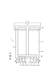
図2に示すように、各発電セル60は、電解質膜・電極構造体(電解質・電極構造体)66と、前記電解質膜・電極構造体66を挟持する第1及び第2セパレータ68、70とを備えるとともに、縦長に構成される。なお、第1及び第2セパレータ68、70は、カーボンセパレータ又は金属セパレータで構成される。
As shown in FIG. 2, each
発電セル60の長辺方向(矢印C方向)の一端縁部(上端縁部)には、矢印A方向に互いに連通して、酸化剤ガス、例えば、酸素含有ガスを供給するための酸化剤ガス供給連通孔72a、及び燃料ガス、例えば、水素含有ガスを供給するための燃料ガス供給連通孔76aが設けられる。
One end edge (upper end edge) of the
発電セル60の長辺方向の他端縁部(下端縁部)には、矢印A方向に互いに連通して、酸化剤ガスを排出するための酸化剤ガス排出連通孔(反応ガス排出連通孔)72b及び燃料ガスを排出するための燃料ガス排出連通孔(反応ガス排出連通孔)76bが設けられる。
The other end edge (lower end edge) in the long side direction of the
発電セル60の短辺方向(矢印B方向)の一端縁部には、冷却媒体を供給するための冷却媒体供給連通孔74aが設けられるとともに、前記発電セル60の短辺方向の他端縁部には、冷却媒体を排出するための冷却媒体排出連通孔74bが設けられる。冷却媒体供給連通孔74a及び冷却媒体排出連通孔74bは、縦長形状に設定される。
A cooling medium
電解質膜・電極構造体66は、例えば、パーフルオロスルホン酸の薄膜に水が含浸された固体高分子電解質膜78と、前記固体高分子電解質膜78を挟持するアノード側電極80及びカソード側電極82とを備える。
The electrolyte membrane /
第1セパレータ68の電解質膜・電極構造体66に向かう面68aには、燃料ガス供給連通孔76aと燃料ガス排出連通孔76bとを連通する燃料ガス流路84が形成される。この燃料ガス流路84は、例えば、矢印C方向に延在する溝部により構成される。第1セパレータ68の面68aとは反対の面68bには、冷却媒体供給連通孔74aと冷却媒体排出連通孔74bとを連通する冷却媒体流路86が形成される。
A fuel
第2セパレータ70の電解質膜・電極構造体66に向かう面70aには、例えば、矢印C方向に延在する溝部からなる酸化剤ガス流路88が設けられるとともに、この酸化剤ガス流路88は、酸化剤ガス供給連通孔72aと酸化剤ガス排出連通孔72bとに連通する。第2セパレータ70の面70aとは反対の面70bには、第1セパレータ68の面68bと重なり合って冷却媒体流路86が一体的に形成される。図示しないが、第1及び第2セパレータ68、70には、必要に応じてシール部材が設けられる。
The
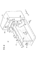
図3に示すように、燃料電池スタック10は、例えば、エンドプレート62a、62bを端板とするケーシング89を備える。なお、ケーシング89に代えて、エンドプレート62a、62b間を図示しないタイロッドで連結して構成してもよい。
As shown in FIG. 3, the
図1に示すように、エンドプレート62aには、冷却媒体入口マニホールド96aと、冷却媒体出口マニホールド96bとが設けられる。冷却媒体入口マニホールド96aは、冷却媒体供給連通孔74aに連通する一方、冷却媒体出口マニホールド96bは、冷却媒体排出連通孔74bに連通する。冷却媒体入口マニホールド96a及び冷却媒体出口マニホールド96bは、冷却媒体供給配管28及び冷却媒体排出配管30を介してラジエータ24に連通している。
As shown in FIG. 1, the
図3に示すように、エンドプレート62bには、酸化剤ガス供給連通孔72aに連通する酸化剤ガス入口マニホールド98a、燃料ガス供給連通孔76aに連通する燃料ガス入口マニホールド100a、酸化剤ガス排出連通孔72bに連通する酸化剤ガス出口マニホールド98b、及び燃料ガス排出連通孔76bに連通する燃料ガス出口マニホールド100bが設けられる。
As shown in FIG. 3, the
図4に示すように、燃料電池スタック10のエンドプレート62bには、加湿器36が固定される。加湿器36のケーシングは、例えば、鋳造成形されており、エンドプレート62bに接するフランジ部106に複数のボルト108が挿入される。ボルト108がエンドプレート62bに螺合することにより、加湿器36が前記エンドプレート62bに直接固定される。
As shown in FIG. 4, the
加湿器36内には、第1及び第2加湿部110a、110bが上下に配列して収容される。第1加湿部110a及び第2加湿部110bは、空気供給配管34と加湿空気供給配管38とに接続される。第1加湿部110a及び第2加湿部110bは、例えば、中空糸膜型加湿構造を採用することができる。加湿器36には、燃料ガス供給機構20を構成する各補機類、例えば、遮断弁46、レギュレータ48、エゼクタ50及び背圧弁42が一体化される。
In the
図3、図5及び図6に示すように、燃料ガス出口マニホールド100bには、出口配管120が連結され、この出口配管120の先端120aがエンドプレート62bから外方に突出する。出口配管120は、電気絶縁材(例えば、樹脂材)又は内面に樹脂コートが施された金属部材で構成されており、水捕集タンク53の室122に先端120aが挿入される(図5及び図6参照)。
As shown in FIGS. 3, 5 and 6, an
図6に示すように、水捕集タンク53の室122に貯留される水の最高水位における水面124は、出口配管120の先端120aの下部よりも下方に距離hだけ離間するように設定される。水捕集タンク53の下部には、室122内の水を外部に排出するためのドレン管126が設けられる。
As shown in FIG. 6, the
このように構成される燃料電池システム12の動作について、以下に説明する。
The operation of the
先ず、図1に示すように、酸化剤ガス供給機構18を構成する空気用ポンプ32が駆動され、酸化剤ガスである外部空気が吸引されて空気供給配管34に導入される。この空気は、空気供給配管34から加湿器36内に導入され、第1及び第2加湿部110a、110bを通って加湿空気供給配管38に供給される(図4参照)。
First, as shown in FIG. 1, the
その際、オフガス供給配管40には、後述するように、反応に使用された酸化剤ガスであるオフガスが供給されている。このため、使用前の空気には、加湿器36の水透過膜(図示せず)を介してオフガス中に含まれる水分が移動し、この使用前の空気が加湿される。加湿された空気は、加湿空気供給配管38からエンドプレート62bを通って燃料電池スタック10内の酸化剤ガス供給連通孔72aに供給される。
At that time, as will be described later, off-gas which is an oxidant gas used for the reaction is supplied to the off-
一方、燃料ガス供給機構20では、遮断弁46の開放作用下に、燃料ガスタンク44内の燃料ガス(水素ガス)がレギュレータ48で降圧された後、エゼクタ50を通って燃料ガス供給配管51からエンドプレート62bを通って燃料電池スタック10内の燃料ガス供給連通孔76aに導入される。
On the other hand, in the fuel
さらに、冷却媒体供給機構16では、冷媒用ポンプ26の作用下に、冷却媒体供給配管28からエンドプレート62aを通って燃料電池スタック10内の冷却媒体供給連通孔74aに冷却媒体が導入される。
Further, in the cooling
図2に示すように、燃料電池スタック10内の発電セル60に供給された空気は、酸化剤ガス供給連通孔72aから第2セパレータ70の酸化剤ガス流路88に導入され、電解質膜・電極構造体66のカソード側電極82に沿って移動する。一方、燃料ガスは、燃料ガス供給連通孔76aから第1セパレータ68の燃料ガス流路84に導入され、電解質膜・電極構造体66のアノード側電極80に沿って移動する。
As shown in FIG. 2, the air supplied to the
従って、各電解質膜・電極構造体66では、カソード側電極82に供給される空気中の酸素と、アノード側電極80に供給される燃料ガス(水素)とが、電極触媒層内で電気化学反応により消費され、発電が行われる。
Therefore, in each electrolyte membrane /
次いで、カソード側電極82に供給されて消費された空気は、酸化剤ガス排出連通孔72bに沿って流動した後、オフガスとしてエンドプレート62bからオフガス供給配管40に排出される(図1参照)。
Next, the air consumed by being supplied to the
同様に、アノード側電極80に供給されて消費された燃料ガスは、燃料ガス排出連通孔76bに排出されて流動し、排出燃料ガスとしてエンドプレート62bから水捕集タンク53を通って排出燃料ガス配管52に排出される(図1参照)。排出燃料ガス配管52に排出された排出燃料ガスは、一部がリターン配管54を通ってエゼクタ50の吸引作用下に燃料ガス供給配管51に戻される。
Similarly, the fuel gas consumed by being supplied to the
排出燃料ガスは、新たな燃料ガスに混在して燃料ガス供給配管51から燃料電池スタック10内に供給される。残余の排出燃料ガスは、パージ弁56の開放作用下に排出される。
The discharged fuel gas is mixed with new fuel gas and supplied into the
ここで、アノード側電極80では、生成水が逆拡散しており、この生成水が燃料ガス排出連通孔76bに排出されている。燃料ガス排出連通孔76bでは、エンドプレート62b側に導入された生成水が、排出燃料ガスの流れに沿って出口配管120を通って水捕集タンク53に送られる。従って、生成水は、出口配管120の先端120aから水捕集タンク53に滴下して前記水捕集タンク53の室122内に貯留(捕集)されている。
Here, in the
この場合、本実施形態では、図6に示すように、室122に貯留される水の最高水位における水面124は、出口配管120の先端120aよりも下方に距離hだけ離間するように設定されている。これにより、出口配管120内の水と水捕集タンク53内の水とによる導電経路が遮断され、簡単且つコンパクトな構成で、液絡が発生することを良好に阻止することができるという効果が得られる。
In this case, in the present embodiment, as shown in FIG. 6, the
また、冷却媒体は、図2に示すように、冷却媒体供給連通孔74aから第1及び第2セパレータ68、70間の冷却媒体流路86に導入された後、矢印B方向に沿って流動する。この冷却媒体は、電解質膜・電極構造体66を冷却した後、冷却媒体排出連通孔74bを移動してエンドプレート62aの冷却媒体出口マニホールド96bから冷却媒体排出配管30に排出される。この冷却媒体は、図1に示すように、ラジエータ24により冷却された後、冷媒用ポンプ26の作用下に冷却媒体供給配管28から燃料電池スタック10に供給される。
As shown in FIG. 2, the cooling medium is introduced into the cooling
なお、本実施形態では、燃料ガス排出連通孔76bから排出される水分を除去するために、排出燃料ガス配管52に水捕集タンク53を設けているが、これに限定されるものではない。例えば、酸化剤ガス排出連通孔72bから排出される水分を除去するために、オフガス供給配管40にも水捕集タンク53を設けることができる。
In the present embodiment, the
また、酸化剤ガスとして高純度の酸素ガスを使用し、上記の燃料ガス循環系と同様に酸素ガス循環系(反応ガス循環系)を構成して、この酸素ガス循環系に水捕集タンク53を設けてもよい。
Further, high-purity oxygen gas is used as the oxidant gas, and an oxygen gas circulation system (reactive gas circulation system) is formed in the same manner as the fuel gas circulation system described above, and the
10…燃料電池スタック 12…燃料電池システム
16…冷却媒体供給機構 18…酸化剤ガス供給機構
20…燃料ガス供給機構 24…ラジエータ
26、32…ポンプ 28…冷却媒体供給配管
30…冷却媒体排出配管 34…空気供給配管
36…加湿器 38…加湿空気供給配管
40…オフガス供給配管 44…燃料ガスタンク
51…燃料ガス供給配管 52…排出燃料ガス配管
53…水捕集タンク 54…リターン配管
60…発電セル 62a、62b…エンドプレート
66…電解質膜・電極構造体 68、70…セパレータ
72a…酸化剤ガス供給連通孔 72b…酸化剤ガス排出連通孔
74a…冷却媒体供給連通孔 74b…冷却媒体排出連通孔
76a…燃料ガス供給連通孔 76b…燃料ガス排出連通孔
78…固体高分子電解質膜 80…アノード側電極
82…カソード側電極 84…燃料ガス流路
86…冷却媒体流路 88…酸化剤ガス流路
96a…冷却媒体入口マニホールド 96b…冷却媒体出口マニホールド
98a…酸化剤ガス入口マニホールド 98b…酸化剤ガス出口マニホールド
100a…燃料ガス入口マニホールド 100b…燃料ガス出口マニホールド
120…出口配管 120a…先端
122…室
DESCRIPTION OF
Claims (2)
前記反応ガス出口に連結され、先端が前記エンドプレートから外方に突出する出口配管と、
前記出口配管の先端から排出される前記反応ガスに含まれる水分を捕集するとともに、前記出口配管の先端よりも下方に水面が位置するように配置される水捕集機構と、
を備えることを特徴とする燃料電池スタック。 A plurality of power generation cells are stacked, provided with a reaction gas supply communication hole and a reaction gas discharge communication hole for circulating the reaction gas used in the power generation reaction in the stacking direction, and an end plate disposed at one end in the stacking direction. Is a fuel cell stack in which a reaction gas outlet communicating with the reaction gas discharge communication hole is opened,
An outlet pipe connected to the reaction gas outlet and having a tip protruding outward from the end plate;
A water collecting mechanism that collects moisture contained in the reaction gas discharged from the tip of the outlet pipe, and is arranged so that a water surface is positioned below the tip of the outlet pipe;
A fuel cell stack comprising:
前記反応ガス循環系に前記水捕集機構が配設されることを特徴とする燃料電池スタック。 The fuel cell stack according to claim 1, further comprising a reactive gas circulation system for circulatingly supplying the reactive gas discharged from the reactive gas outlet to the reactive gas supply passage.
The fuel cell stack, wherein the water collection mechanism is disposed in the reaction gas circulation system.
Priority Applications (1)
| Application Number | Priority Date | Filing Date | Title |
|---|---|---|---|
| JP2008162829A JP5474318B2 (en) | 2008-06-23 | 2008-06-23 | Fuel cell stack |
Applications Claiming Priority (1)
| Application Number | Priority Date | Filing Date | Title |
|---|---|---|---|
| JP2008162829A JP5474318B2 (en) | 2008-06-23 | 2008-06-23 | Fuel cell stack |
Publications (2)
| Publication Number | Publication Date |
|---|---|
| JP2010003603A true JP2010003603A (en) | 2010-01-07 |
| JP5474318B2 JP5474318B2 (en) | 2014-04-16 |
Family
ID=41585153
Family Applications (1)
| Application Number | Title | Priority Date | Filing Date |
|---|---|---|---|
| JP2008162829A Active JP5474318B2 (en) | 2008-06-23 | 2008-06-23 | Fuel cell stack |
Country Status (1)
| Country | Link |
|---|---|
| JP (1) | JP5474318B2 (en) |
Cited By (3)
| Publication number | Priority date | Publication date | Assignee | Title |
|---|---|---|---|---|
| JP2011154909A (en) * | 2010-01-27 | 2011-08-11 | Honda Motor Co Ltd | Fuel cell stack |
| JP2012038467A (en) * | 2010-08-04 | 2012-02-23 | Honda Motor Co Ltd | Fuel cell stack |
| US9368813B2 (en) | 2012-06-04 | 2016-06-14 | Honda Motor Co., Ltd. | Drainage structure for gas outlet region in fuel cell stack |
Citations (9)
| Publication number | Priority date | Publication date | Assignee | Title |
|---|---|---|---|---|
| JPH113722A (en) * | 1997-06-09 | 1999-01-06 | Fuji Electric Co Ltd | Steam separator for fuel cell |
| JP2000090954A (en) * | 1998-09-16 | 2000-03-31 | Honda Motor Co Ltd | Fuel cell stack |
| JP2003190725A (en) * | 2001-12-25 | 2003-07-08 | Maruyasu Industries Co Ltd | Gas-liquid separator |
| JP2004327059A (en) * | 2003-04-21 | 2004-11-18 | Honda Motor Co Ltd | Fuel cell stack |
| JP2005251526A (en) * | 2004-03-03 | 2005-09-15 | Honda Motor Co Ltd | Fuel cell stack |
| JP2006120455A (en) * | 2004-10-21 | 2006-05-11 | Toyota Motor Corp | Muffler for fuel cell |
| JP2006120503A (en) * | 2004-10-22 | 2006-05-11 | Honda Motor Co Ltd | Vapor-liquid separator for on-vehicle fuel cell |
| JP2007184144A (en) * | 2006-01-06 | 2007-07-19 | Toyota Motor Corp | Gas/liquid separator for fuel cell |
| JP2007265676A (en) * | 2006-03-27 | 2007-10-11 | Nissan Motor Co Ltd | Fuel cell system |
-
2008
- 2008-06-23 JP JP2008162829A patent/JP5474318B2/en active Active
Patent Citations (9)
| Publication number | Priority date | Publication date | Assignee | Title |
|---|---|---|---|---|
| JPH113722A (en) * | 1997-06-09 | 1999-01-06 | Fuji Electric Co Ltd | Steam separator for fuel cell |
| JP2000090954A (en) * | 1998-09-16 | 2000-03-31 | Honda Motor Co Ltd | Fuel cell stack |
| JP2003190725A (en) * | 2001-12-25 | 2003-07-08 | Maruyasu Industries Co Ltd | Gas-liquid separator |
| JP2004327059A (en) * | 2003-04-21 | 2004-11-18 | Honda Motor Co Ltd | Fuel cell stack |
| JP2005251526A (en) * | 2004-03-03 | 2005-09-15 | Honda Motor Co Ltd | Fuel cell stack |
| JP2006120455A (en) * | 2004-10-21 | 2006-05-11 | Toyota Motor Corp | Muffler for fuel cell |
| JP2006120503A (en) * | 2004-10-22 | 2006-05-11 | Honda Motor Co Ltd | Vapor-liquid separator for on-vehicle fuel cell |
| JP2007184144A (en) * | 2006-01-06 | 2007-07-19 | Toyota Motor Corp | Gas/liquid separator for fuel cell |
| JP2007265676A (en) * | 2006-03-27 | 2007-10-11 | Nissan Motor Co Ltd | Fuel cell system |
Cited By (3)
| Publication number | Priority date | Publication date | Assignee | Title |
|---|---|---|---|---|
| JP2011154909A (en) * | 2010-01-27 | 2011-08-11 | Honda Motor Co Ltd | Fuel cell stack |
| JP2012038467A (en) * | 2010-08-04 | 2012-02-23 | Honda Motor Co Ltd | Fuel cell stack |
| US9368813B2 (en) | 2012-06-04 | 2016-06-14 | Honda Motor Co., Ltd. | Drainage structure for gas outlet region in fuel cell stack |
Also Published As
| Publication number | Publication date |
|---|---|
| JP5474318B2 (en) | 2014-04-16 |
Similar Documents
| Publication | Publication Date | Title |
|---|---|---|
| JP5220495B2 (en) | Fuel cell stack | |
| JP4456188B2 (en) | Fuel cell stack | |
| JP5965423B2 (en) | Fuel cell vehicle | |
| JP5354941B2 (en) | Fuel cell system | |
| JP2008226711A (en) | Fuel cell system | |
| JP4824375B2 (en) | In-vehicle fuel cell system | |
| JP4598638B2 (en) | In-vehicle fuel cell system | |
| JP2012134067A (en) | Fuel cell system | |
| JP5354942B2 (en) | Fuel cell system | |
| JP5354943B2 (en) | Fuel cell system | |
| JP5474318B2 (en) | Fuel cell stack | |
| JP7130616B2 (en) | fuel cell system | |
| JP5372668B2 (en) | Fuel cell stack | |
| US9105915B2 (en) | Fuel cell stack coupled to a humidifier via an inclined channel | |
| JP5350966B2 (en) | Humidification module | |
| JP5366635B2 (en) | Fuel cell system | |
| JP5214298B2 (en) | Fuel cell system | |
| JP5103411B2 (en) | Fuel cell stack | |
| JP5430318B2 (en) | Fuel cell stack | |
| JP5450312B2 (en) | Fuel cell stack | |
| JP5404542B2 (en) | Fuel cell stack | |
| JP5329112B2 (en) | Fuel cell system | |
| JP2012022865A (en) | Fuel battery stack | |
| JP4643968B2 (en) | Fuel cell system | |
| JP5504077B2 (en) | Fuel cell stack |
Legal Events
| Date | Code | Title | Description |
|---|---|---|---|
| A621 | Written request for application examination |
Free format text: JAPANESE INTERMEDIATE CODE: A621 Effective date: 20101125 |
|
| A131 | Notification of reasons for refusal |
Free format text: JAPANESE INTERMEDIATE CODE: A131 Effective date: 20121002 |
|
| A521 | Written amendment |
Free format text: JAPANESE INTERMEDIATE CODE: A523 Effective date: 20121130 |
|
| A131 | Notification of reasons for refusal |
Free format text: JAPANESE INTERMEDIATE CODE: A131 Effective date: 20130528 |
|
| A521 | Written amendment |
Free format text: JAPANESE INTERMEDIATE CODE: A523 Effective date: 20130726 |
|
| TRDD | Decision of grant or rejection written | ||
| A01 | Written decision to grant a patent or to grant a registration (utility model) |
Free format text: JAPANESE INTERMEDIATE CODE: A01 Effective date: 20140107 |
|
| A61 | First payment of annual fees (during grant procedure) |
Free format text: JAPANESE INTERMEDIATE CODE: A61 Effective date: 20140205 |
|
| R150 | Certificate of patent or registration of utility model |
Ref document number: 5474318 Country of ref document: JP Free format text: JAPANESE INTERMEDIATE CODE: R150 Free format text: JAPANESE INTERMEDIATE CODE: R150 |