JP6986027B2 - Tugboat with capsizing and sinking prevention system - Google Patents

Tugboat with capsizing and sinking prevention system Download PDF

Info

Publication number
JP6986027B2
JP6986027B2 JP2018551945A JP2018551945A JP6986027B2 JP 6986027 B2 JP6986027 B2 JP 6986027B2 JP 2018551945 A JP2018551945 A JP 2018551945A JP 2018551945 A JP2018551945 A JP 2018551945A JP 6986027 B2 JP6986027 B2 JP 6986027B2
Authority
JP
Japan
Prior art keywords
tugboat
control unit
towline
electronic control
thrust
Prior art date
Legal status (The legal status is an assumption and is not a legal conclusion. Google has not performed a legal analysis and makes no representation as to the accuracy of the status listed.)
Active
Application number
JP2018551945A
Other languages
Japanese (ja)
Other versions
JP2019510679A5 (en
JP2019510679A (en
Inventor
バングスランド,トーマス
Original Assignee
エー・ピー・モラー−マースク エー/エス
Priority date (The priority date is an assumption and is not a legal conclusion. Google has not performed a legal analysis and makes no representation as to the accuracy of the date listed.)
Filing date
Publication date
Application filed by エー・ピー・モラー−マースク エー/エス filed Critical エー・ピー・モラー−マースク エー/エス
Publication of JP2019510679A publication Critical patent/JP2019510679A/en
Publication of JP2019510679A5 publication Critical patent/JP2019510679A5/ja
Application granted granted Critical
Publication of JP6986027B2 publication Critical patent/JP6986027B2/en
Active legal-status Critical Current
Anticipated expiration legal-status Critical

Links

Images

Classifications

    • BPERFORMING OPERATIONS; TRANSPORTING
    • B63SHIPS OR OTHER WATERBORNE VESSELS; RELATED EQUIPMENT
    • B63BSHIPS OR OTHER WATERBORNE VESSELS; EQUIPMENT FOR SHIPPING 
    • B63B43/00Improving safety of vessels, e.g. damage control, not otherwise provided for
    • B63B43/02Improving safety of vessels, e.g. damage control, not otherwise provided for reducing risk of capsizing or sinking
    • BPERFORMING OPERATIONS; TRANSPORTING
    • B63SHIPS OR OTHER WATERBORNE VESSELS; RELATED EQUIPMENT
    • B63BSHIPS OR OTHER WATERBORNE VESSELS; EQUIPMENT FOR SHIPPING 
    • B63B35/00Vessels or similar floating structures specially adapted for specific purposes and not otherwise provided for
    • B63B35/66Tugs
    • B63B35/68Tugs for towing
    • BPERFORMING OPERATIONS; TRANSPORTING
    • B63SHIPS OR OTHER WATERBORNE VESSELS; RELATED EQUIPMENT
    • B63HMARINE PROPULSION OR STEERING
    • B63H21/00Use of propulsion power plant or units on vessels
    • B63H21/21Control means for engine or transmission, specially adapted for use on marine vessels

Landscapes

  • Chemical & Material Sciences (AREA)
  • Engineering & Computer Science (AREA)
  • Combustion & Propulsion (AREA)
  • Mechanical Engineering (AREA)
  • Ocean & Marine Engineering (AREA)
  • Control Of Position, Course, Altitude, Or Attitude Of Moving Bodies (AREA)
  • Selective Calling Equipment (AREA)
  • Jib Cranes (AREA)
  • Alarm Systems (AREA)
  • Traffic Control Systems (AREA)

Description

本開示は、船舶の操縦を支援するためのタグボートに関する。 The present disclosure relates to tugboats to assist in maneuvering vessels.

例えば、入港、接岸、離岸、および出港する貨物船のような船舶を支援するための支援操作は、従来方式では、0〜8人の熟練船員のような多数の他の乗組員によって支援される船長によって操作される有人タグボートによって行われる。船舶は、一般的には、港湾環境の制約内では、自力で操縦することができないので、この支援が必要である。1隻または複数隻のタグボートは、タグボート上のウィンチを船舶上のキャプスタンまたはボラードに接続する曳航索を使用して船舶を曳航するのに使用される。船舶上の接続点は、船尾の近くまたは船首の近くに位置し得るが、船尾と船首との間のどの場所にも位置し得る。さらに、1隻または複数隻のタグボートは、必要に応じて、船舶を押すのに使用され得る。この点に関して、タグボートの船首は、支援すべき船舶(以降、「被支援船舶」と呼ぶ)の船体上のストロングポイント(押し位置)に係合する。通常、船体上のストロングポイントには、タグボートの乗組員がストロングポイントの位置を識別することができるように、大きな文字TUGが印されている。 For example, assistive operations to assist vessels such as cargo ships entering, berthing, leaving, and leaving the port are traditionally assisted by a large number of other crew members, such as 0-8 skilled seafarers. It is done by a manned tugboat operated by the captain. Vessels generally cannot operate on their own within the constraints of the port environment and need this assistance. One or more tugboats are used to tow a vessel using a towline that connects the winch on the tugboat to the capstan or bollard on the vessel. Connection points on the ship can be located near the stern or near the bow, but can be located anywhere between the stern and the bow. In addition, one or more tugboats may be used to push the vessel, if desired. In this regard, the bow of the tugboat engages a strong point (push position) on the hull of the vessel to be supported (hereinafter referred to as the "supported vessel"). Strong points on the hull are usually marked with a large letter TUG so that the tugboat crew can identify the location of the strong point.

一般に、タグボートは、水空間、港湾、入り江、可航水路、湖、および河川において運航するボートであり、タグボートの目的は、タグボートのエンジンおよび推進器を使用して、タグボートから曳航/支援すべき船舶に力学的エネルギーを伝達することである。タグボートは、強力なディーゼル電気駆動装置またはディーゼル駆動装置を装備することによりタグボートの作業に適応され、大きな引張力/押す力(ボラードプル)を発生させるために、極めて高い出力対トン数比を有する。 In general, tugboats are boats that operate in water spaces, harbors, coves, navigators, lakes, and rivers, and the purpose of tugboats should be tow / support from tugboats using tugboat engines and propulsion devices. It is the transfer of mechanical energy to the ship. The tugboat is adapted to the tugboat work by equipping it with a powerful diesel electric drive or diesel drive and has an extremely high output-tonnage ratio to generate a large tensile / pushing force (bolado pull).

タグボートの出力は、一般的には、エンジンの馬力およびタグボートの総ボラードプルで表される。コンテナ船等を曳航するために使用される2000年代〜2010年代の最大商業港タグボートは、約60〜65トンのボラードプルを有するものであった。これは、「標準」タグボートより15トン大きいと考えられる。 The output of a tugboat is generally expressed in terms of engine horsepower and total tugboat pull. The largest commercial port tugboats of the 2000s and 2010s used to tow container ships and the like had a borad pull of about 60 to 65 tons. This is considered to be 15 tonnes larger than a "standard" tugboat.

タグボートは、非常に操縦しやすく、操縦性および安全性を向上させるために様々な推進システムが開発されてきた。ほとんどのタグボートは、プロペラ駆動型である。kW/hp当たりの推進力を増すために、コルトノズルが追加されている。ノズルラダーを使用すると、従来のラダーを使用する必要がなくなる。タグボートには、一般的には、いわゆるZドライブまたは(アジマススラスタ)が設けられており、これは、360°回転することができるポッドであり、推力方向の急速な変化を可能にする。 Tugboats are extremely manoeuvrable and various propulsion systems have been developed to improve maneuverability and safety. Most tugs are propeller driven. A Colt nozzle has been added to increase propulsion per kW / hp. Using a nozzle ladder eliminates the need to use a conventional ladder. Tugboats are typically equipped with so-called Z-drives or (azimuth thrusters), which are pods that can rotate 360 ° and allow rapid changes in thrust direction.

追加として、または代替として、タグボートには、専用舶用推進システムであるサイクロイドドライブとしても周知のフォイト・シュナイダー・プロペラ(VSP)が設けられている。VSPは、非常に操縦しやすく、ほとんど瞬時に推力の方向を変えることができる。VSPは、タグボートで広く使用されている。垂直ブレード(水中翼の形状)の円形配列は、垂直軸を中心として回転する円板から、ボートの底の外に突出している。各々のブレードは、垂直軸を中心として回転し得る。内歯車は、円板の回転と同期してブレードの迎え角を変化させるので、各々のブレードは、ヘリコプタのコレクティブピッチコントロールおよび周期と非常に似た形で、任意の方向に推力を生成し得る。 In addition or as an alternative, tugboats are equipped with a Foyt Schneider propeller (VSP), also known as a cycloidal drive, a dedicated marine propulsion system. The VSP is very easy to maneuver and can change the direction of thrust almost instantly. VSPs are widely used in tugboats. A circular array of vertical blades (the shape of a hydrofoil) projects out of the bottom of the boat from a disk that rotates about a vertical axis. Each blade can rotate about a vertical axis. Since the internal gear changes the angle of attack of the blades in synchronization with the rotation of the disk, each blade can generate thrust in any direction, much like the collective pitch control and period of the helicopter. ..

タグボート運航、すなわち、船舶支援操作の運用コストは、乗組員に対する費用が大きな割合を占める。したがって、タグボート操作の費用を低減することが求められる。 The cost of tugboat operation, that is, the operation cost of ship support operation, accounts for a large proportion of the cost to the crew. Therefore, it is required to reduce the cost of tugboat operation.

タグボートは、現状では、引張力および推力の不注意な組み合わせにより転覆または沈没する可能性がある。このような状況は、通常は、経験豊富な船長によって回避されるが、乗組員が対応策をとることができない場合、またはタグボートが無人ボートである場合は、このような状況における保護を強化する必要がある。 Tugboats can currently capsize or sink due to inadvertent combinations of tensile and thrust forces. Such situations are usually avoided by experienced captains, but if the crew is unable to take action or if the tugboat is an unmanned boat, the protection in such situations will be enhanced. There is a need.

本発明の目的は、上記の問題を克服する、または少なくとも低減するシステムを提供することである。 An object of the present invention is to provide a system that overcomes, or at least reduces, the above problems.

上述の目的および他の目的は、独立請求項の特徴によって達成される。さらなる実装形態は、従属請求項、説明および図面から明らかである。 The above and other objectives are achieved by the characteristics of the independent claims. Further implementations are apparent from the dependent claims, description and drawings.

第1の態様によれば、船舶の操縦を支援するためのタグボートであって、推力の制御可能な方向を有する1つまたは複数の推進器を駆動するエンジンと、被支援船舶とタグボートとの間の引張接続を確立するための曳航索と、曳航索がタグボートに及ぼす引張力の大きさおよび方向を検知するように構成された第1のセンサ装置と、タグボートの向きを検知するように構成された第2のセンサ装置と、第1のセンサ装置からの信号を受信し、第2のセンサ装置からの信号を受信するコントローラとを備え、コントローラには、1つまたは複数の推進器によって生成された推力の大きさおよび方向が伝えられ、コントローラは、検知された推力の大きさならびに方向、検知された引張力の大きさならびに方向、および検知されたタグボートの向きに基づいて、安全閾値を超えたかどうかを判断するように構成される、タグボートが提供される。 According to the first aspect, a tugboat for assisting the maneuvering of a ship, between an engine driving one or more propulsion units having a controllable direction of thrust, between the supported ship and the tugboat. A towline for establishing a tugboat, a first sensor device configured to detect the magnitude and direction of the tugboat's tensile force on the tugboat, and a tugboat orientation. It comprises a second sensor device and a controller that receives signals from the first sensor device and receives signals from the second sensor device, the controller being generated by one or more propulsion units. The magnitude and direction of the tugboat is communicated and the controller exceeds the safety threshold based on the magnitude and direction of the detected thrust, the magnitude and direction of the detected tugboat, and the orientation of the detected tugboat. A tugboat is provided that is configured to determine if it was.

タグボートに作用する力およびタグボートの向きが伝えられるコントローラをタグボートに配設することによって、例えば、曳航索の過剰な力によるタグボートの転覆および/または沈没を防止する自動システムを形成することができる。 By disposing a controller on the tugboat that conveys the force acting on the tugboat and the orientation of the tugboat, for example, an automated system can be formed to prevent capsizing and / or sinking of the tugboat due to excessive force of the tugboat.

第1の態様の第1の可能な実施形態では、タグボートが安全閾値を超えているとコントローラが判断した場合に、コントローラは、推力の大きさを低減し、および/または推力の方向を変更するように構成される。 In the first possible embodiment of the first aspect, if the controller determines that the tugboat has exceeded the safety threshold, the controller reduces the magnitude of the thrust and / or changes the direction of the thrust. It is configured as follows.

第1の態様の第2の可能な実施形態ではタグボートには、コントローラからのコマンドに応答して、タグボートを曳航索から切り離す装置が設けられ、該装置は、好ましくは、曳航索を切断する器具を備える。 In the second possible embodiment of the first aspect, the tugboat is provided with a device for disconnecting the tugboat from the towline in response to a command from the controller, the device being preferably an instrument for cutting the towline. To prepare for.

第1の態様の第3の可能な実施形態では、タグボートが安全閾値を超えているとコントローラが判断した場合に、コントローラは、曳航索を切断するように構成される。 In a third possible embodiment of the first aspect, the controller is configured to disconnect the towline if the controller determines that the tugboat has exceeded the safety threshold.

第1の態様の第4の可能な実施形態では、第1の安全閾値ならびに第2の安全閾値はタグボートが転覆するリスクであり、および/または第1の安全閾値ならびに第2の安全閾値はタグボートが沈没するリスクである。 In a fourth possible embodiment of the first aspect, the first safety threshold and the second safety threshold are the risks of the tagboat overturning, and / or the first safety threshold and the second safety threshold are the tagboat. Is the risk of sinking.

第1の態様の第5の可能な実施形態では、コントローラは、タグボートの挙動をシミュレートするコンピュータモデルに基づいて、タグボートが転覆または沈没するリスクを判断するように構成される。 In a fifth possible embodiment of the first aspect, the controller is configured to determine the risk of capsizing or sinking of the tugboat based on a computer model that simulates the behavior of the tugboat.

第1の態様の第6の可能な実施形態では、タグボートは、自律動作タグボート、無人タグボート、および/または被遠隔制御タグボートである。 In a sixth possible embodiment of the first aspect, the tugboat is an autonomous tugboat, an unmanned tugboat, and / or a remotely controlled tugboat.

第1の態様の第7の可能な実施形態では、コントローラには、前記タグボートの数学モデルが設けられる。 In a seventh possible embodiment of the first aspect, the controller is provided with a mathematical model of the tugboat.

第2の態様によれば、タグボートを操作する方法であって、タグボートの推進器によって生成された推力の大きさおよび方向を決定することと、曳航索によってタグボートに加えられる引張力の大きさおよび方向を決定することと、タグボートの向きを決定することと、推力の大きさならびに方向、引張力の大きさならびに方向、およびタグボートの向きの組み合わせが安全閾値を超えているかどうかを判断することとを含む、方法が提供される。 According to the second aspect, it is a method of operating a tugboat, which determines the magnitude and direction of the thrust generated by the tugboat propulsion, and the magnitude and magnitude of the tensile force applied to the tugboat by towing. Determining the direction, determining the orientation of the tugboat, and determining whether the combination of thrust magnitude and direction, tensile force magnitude and direction, and tugboat orientation exceeds the safety threshold. Methods are provided, including.

第2の態様の第1の可能な実施形態では、該方法は、タグボートが安全閾値を超えないように、推力の大きさおよび/または方向を調整することをさらに含む。 In the first possible embodiment of the second aspect, the method further comprises adjusting the magnitude and / or direction of thrust so that the tugboat does not exceed the safety threshold.

第2の態様の第1の可能な実施形態では、該方法は、タグボートが安全閾値を超えたときに、推力の大きさおよび/または方向を調整することをさらに含む。 In the first possible embodiment of the second aspect, the method further comprises adjusting the magnitude and / or direction of thrust when the tugboat exceeds the safety threshold.

本発明の上記の態様および他の態様は、以下に説明する実施形態から明らかになるであろう。 The above and other aspects of the invention will become apparent from the embodiments described below.

本開示の以下の詳細な説明部分において、図面に示された実施形態例を参照しながら、本発明をより詳細に説明する。 In the following detailed description of the present disclosure, the invention will be described in more detail with reference to examples of embodiments shown in the drawings.

支援操作の間の被支援船舶および複数のタグボートの側面図である。It is a side view of a supported vessel and a plurality of tugboats during a support operation. 支援操作の間の図1の被支援船舶および複数のタグボートの上面図であり、1隻の追加のタグボートが被支援船舶の横側に位置する状態を示した図である。It is a top view of the supported vessel and a plurality of tugboats of FIG. 1 during a support operation, and is a diagram showing a state in which one additional tugboat is located on the side of the supported vessel. 支援操作の間の図1の被支援船舶および複数のタグボートの上面図であり、2隻の追加のタグボートが被支援船舶の横側に位置する状態を示した図である。It is a top view of the supported vessel and a plurality of tugboats of FIG. 1 during a support operation, and is a diagram showing a state in which two additional tugboats are located on the side of the supported vessel. システム内にパイロット用の遠隔制御ユニット、制御センター用の遠隔制御ユニットおよび各々のタグボート用の制御ユニットを有するシステムの系統図である。It is a system diagram of the system which has the remote control unit for a pilot, the remote control unit for a control center, and the control unit for each tugboat in a system. クレーンアームが休止位置にあるタグボートの側面図である。It is a side view of a tugboat in which a crane arm is in a dormant position. 曳航索を保持する上昇位置にある図5のタグボートの側面図である。It is a side view of the tugboat of FIG. 5 in the ascending position which holds the towline. クレーンが休止位置にある図5のタグボートの上面図である。FIG. 5 is a top view of the tugboat of FIG. 5 in which the crane is in a dormant position. 図5のタグボートの正面図である。It is a front view of the tugboat of FIG. クレーンが受取人に曳航索を渡す動作位置にある図5のタグボートの上面図である。It is a top view of the tugboat of FIG. 5 in the operating position where the crane passes the towline to the recipient. 図5のタグボートの操作を制御するためのシステムのブロック図である。It is a block diagram of the system for controlling the operation of the tugboat of FIG. 把持具の第1の実施形態の側面図である。It is a side view of the 1st Embodiment of a gripper. 図11の把持具の別の側面図である。It is another side view of the gripping tool of FIG. 把持具の第2の実施形態の側面図である。It is a side view of the 2nd Embodiment of a gripper. 図13の把持具の別の側面図である。It is another side view of the gripping tool of FIG. 堅硬なアイスプライスを有する曳航索の上面図である。It is a top view of a towline having a solid ice price. 柔軟なアイスプライスを有する曳航索の上面図である。It is a top view of a towline having a flexible ice price. クレーンアーム用の支持部を有するガイドビットの斜視図である。It is a perspective view of the guide bit which has the support part for a crane arm. 図5のタグボートを操作する方法を示したフローチャートである。It is a flowchart which showed the method of operating the tugboat of FIG. 図5のタグボートを操作する方法を示したフローチャートである。It is a flowchart which showed the method of operating the tugboat of FIG. 図5のタグボートを操作する方法を示したフローチャートである。It is a flowchart which showed the method of operating the tugboat of FIG. 図5のタグボートを操作する方法を示したフローチャートである。It is a flowchart which showed the method of operating the tugboat of FIG. 図5のタグボートを操作する方法を示したフローチャートである。It is a flowchart which showed the method of operating the tugboat of FIG. 図5のタグボートを操作する方法を示したフローチャートである。It is a flowchart which showed the method of operating the tugboat of FIG. 図5のタグボートを操作する方法を示したフローチャートである。It is a flowchart which showed the method of operating the tugboat of FIG. 図5のタグボートを操作する方法を示したフローチャートである。It is a flowchart which showed the method of operating the tugboat of FIG. 制御センターのブロック図である。It is a block diagram of a control center. 図26の制御センターの上面図である。It is a top view of the control center of FIG. 26. パイロット用の携帯型制御ユニットの上面図である。It is a top view of the portable control unit for a pilot. 図28の携帯型制御ユニットのブロック図である。It is a block diagram of the portable control unit of FIG. 28. 図28の携帯型制御ユニットのタッチスクリーンのスクリーンショットである。FIG. 28 is a screenshot of the touch screen of the portable control unit of FIG. 28. 図28の携帯型制御ユニットのタッチスクリーンのスクリーンショットである。FIG. 28 is a screenshot of the touch screen of the portable control unit of FIG. 28. 電気接続部が短いクレーンを有するボートの上面図である。It is a top view of a boat having a crane with a short electrical connection. 衝突防止を示すチャートである。It is a chart which shows collision prevention.

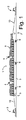
図1は、支援操作の間の被支援船舶1および複数のタグボート2の側面図である。図2は、同じ船舶1または別の船舶1であり得る被支援船舶1の上面図であり、1隻の追加のタグボートが被支援船舶1の側面を押している状態を示した図である。図3は、被支援船舶1の別の上面図であり、2隻のタグボートが被支援船舶1の側面から引っ張っている状態を示した図である。支援操作に関与するタグボート2の数は、被支援船舶1のサイズ、自力で操縦するための被支援船舶1の積載力、および個々のタグボート2によってもたらされ得る引張力(ボラードプル)に依存する。一般的には、タグボート2は、少なくとも40トン、好ましくは少なくとも50トン、さらに好ましくは少なくとも60トンのボラードプルを発生させることができる。被支援船舶1は、例えば、貨物船のような支援を必要とする任意のタイプの船舶1であり得、図1ではコンテナ船が例として示されている。この例は、船尾6のより近くに排ガス用の煙突4および船首7のより近くにブリッジ5を有するように設計された、いわゆるツインアイランド方式のコンテナ船を示している。コンテナ8は、甲板上に積み上げられた状態で示されており、通常は、甲板の下にも積み込まれる。船体3の側面には、船体3を押すタグボート2によって係合されるのに適した船体上の位置を示すために、「TUG」という文字で印されたストロングポイント9が設けられている。 FIG. 1 is a side view of a supported vessel 1 and a plurality of tugboats 2 during a support operation. FIG. 2 is a top view of a supported vessel 1, which may be the same vessel 1 or another vessel 1, showing a state in which one additional tugboat is pushing the side surface of the supported vessel 1. FIG. 3 is another top view of the supported vessel 1, showing a state in which two tugboats are pulled from the side surface of the supported vessel 1. The number of tugboats 2 involved in the assisted operation depends on the size of the supported vessel 1, the loading capacity of the assisted vessel 1 for self-maneuvering, and the tensile force (bolard pull) that can be provided by the individual tugboats 2. .. In general, the tugboat 2 can generate at least 40 tonnes, preferably at least 50 tonnes, more preferably at least 60 tonnes of borad pull. The supported vessel 1 can be any type of vessel 1 that requires assistance, such as a cargo ship, and in FIG. 1, a container vessel is shown as an example. This example shows a so-called twin-island container ship designed to have a chimney 4 for exhaust gas closer to the stern 6 and a bridge 5 closer to the bow 7. The container 8 is shown stacked on the deck and is usually also loaded under the deck. A strong point 9 marked with the letters "TUG" is provided on the side surface of the hull 3 to indicate a suitable position on the hull to be engaged by the tugboat 2 pushing the hull 3.

船舶1には、曳航索10を取り付けるために、船舶の側面に沿っていくつかの位置にボラードおよびキャプスタンが設けられる。一般的には、ボラードおよびキャプスタンは、船尾6の近くおよび船首7の近くに、船体3の側面に沿って等間隔に設けられる。曳航索10は、実際の要求に応じて、船舶1の適切な位置に取り付けられる。したがって、曳航索10の一端は船舶1に取り付けられ、曳航索10の他端はタグボート2に取り付けられる Vessel 1 is provided with bollards and capstans at several positions along the sides of the vessel to attach the towline 10. Generally, bollards and capstans are evenly spaced along the sides of the hull 3 near the stern 6 and near the bow 7. The towing line 10 is mounted at an appropriate position on the vessel 1 according to actual requirements. Therefore, one end of the towing line 10 is attached to the ship 1, and the other end of the towing line 10 is attached to the tugboat 2.

支援操作時には、パイロットは被支援船舶1に乗船し、パイロットはタグボート2の推力動作の制御を担当する。従来の手順では、パイロットは、無線通信を介して個々のタグボートの船長に推力コマンドを出すことになる。 At the time of the support operation, the pilot is on board the supported ship 1, and the pilot is in charge of controlling the thrust operation of the tugboat 2. In the conventional procedure, the pilot would issue thrust commands to the captains of individual tugboats via wireless communication.

本発明の実施形態は、好ましくは無人であり、好ましくは部分的に遠隔制御であり、好ましくは部分的に自律的に動作するタグボート2に関する。タグボート2は、好ましくは、(無線で)受信した指示に応答して部分的に自律的に動作することができ、部分的に直接(無線)遠隔制御下で動作することができる。 Embodiments of the present invention relate to a tugboat 2, preferably unmanned, preferably partially remote controlled, and preferably partially autonomously operated. The tugboat 2 can preferably operate partially autonomously in response to an instruction received (wirelessly) and can operate partially directly (wirelessly) under remote control.

図4は、タグボート2を制御するためのシステムを示す系統図である。各々のタグボート2には、無線通信手段を装備した電子制御ユニット50が設けられる。関与するタグボート2の数は、1〜nの番号で図示されているように、変化し得る。無線通信手段を有するシステムコントローラ250は制御センター200に設けられ、無線通信手段を有するリモートコントローラ150は、例えば、被支援船舶1上のパイロットに提供される。タグボート2は、プログラムされた指示に基づいて自律的に動作し、制御センター200のシステムコントローラ250からの指示に基づいて半自律的に動作し、またはパイロットによって操作される遠隔制御ユニット150からの指示に基づいて直接遠隔制御で動作する。 FIG. 4 is a system diagram showing a system for controlling the tugboat 2. Each tugboat 2 is provided with an electronic control unit 50 equipped with wireless communication means. The number of tugboats 2 involved can vary, as illustrated by numbers 1-n. The system controller 250 having wireless communication means is provided in the control center 200, and the remote controller 150 having wireless communication means is provided to, for example, a pilot on the supported vessel 1. The tugboat 2 operates autonomously based on programmed instructions, semi-autonomously based on instructions from the system controller 250 of the control center 200, or instructions from a remote control unit 150 operated by a pilot. Operates directly with remote control based on.

システムコントローラ250は、例えば、陸上の制御センター200に配置され、通常は、タグボート2を視認できる状態にない。システムコントローラ250は、船隊または複数のタグボート2を制御する。システムコントローラ250は、どのタグボート2を作業に送るかを決定し、係船位置から動員位置まで、および動員位置から係船位置までタグボート2のナビゲートを指示する。したがって、システムコントローラ250は、特定の位置までナビゲートするようにタグボート2に対して指示するのに使用され、一実施形態では、タグボート2は、指示を受信した後、自律的に特定の位置までナビゲートする。タグボート2が動員位置に到着すると、タグボート2の制御は、遠隔制御ユニット150を使用するパイロットに引き継がれる。遠隔制御ユニット150は、船舶1の操縦を支援しながらタグボート2を制御するのに使用される。遠隔制御ユニット150は、パイロットによって操作され、パイロットは、一般的には、船舶1の操縦を支援するのに使用されるタグボート2を視認できる状態にある。 The system controller 250 is located, for example, in the control center 200 on land, and normally, the tugboat 2 is not in a visible state. The system controller 250 controls the fleet or a plurality of tugboats 2. The system controller 250 determines which tugboat 2 to send to work and directs navigation of the tugboat 2 from mooring position to mobilization position and from mobilization position to mooring position. Therefore, the system controller 250 is used to instruct the tugboat 2 to navigate to a specific position, and in one embodiment, the tugboat 2 autonomously reaches a specific position after receiving the instruction. Navigate. When the tugboat 2 arrives at the mobilization position, control of the tugboat 2 is taken over by the pilot using the remote control unit 150. The remote control unit 150 is used to control the tugboat 2 while assisting the maneuvering of the vessel 1. The remote control unit 150 is operated by the pilot so that the pilot can see the tugboat 2, which is generally used to assist the maneuvering of the vessel 1.

遠隔制御センター200または遠隔制御ユニット150に信号を送信するクレーン上のカメラにより、遠隔制御センター200のオペレータまたは遠隔制御ユニット150を使用するパイロットの操作が可能になる。 A camera on a crane that sends a signal to the remote control center 200 or the remote control unit 150 allows the operator of the remote control center 200 or the pilot using the remote control unit 150 to operate.

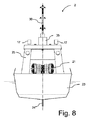
図5〜図9は、船舶1の操縦を支援するのに使用され得るタグボート2の一実施形態例である。タグボート2は、スケグ24が設けられた船体23を備える。船体23は、船尾26から船首27まで延在する。船体23には、周方向フェンダ29が設けられる。 5 to 9 are examples of an embodiment of a tugboat 2 that can be used to assist the maneuvering of a vessel 1. The tugboat 2 includes a hull 23 provided with a skeg 24. The hull 23 extends from the stern 26 to the bow 27. A circumferential fender 29 is provided on the hull 23.

1つまたは2つのアジマススラスタ28(ノズルドライブ)の形状の1つまたは2つの推進器は、船尾26の近くに設けられ(他の位置も可能である)、任意の所望の方向(水平方向)の推力を発生させる。アジマススラスタ28は、推力(例えば、少なくとも40トンのボラードプル)を発生させるために、内燃機関(ディーゼルエンジン)またはディーゼル電気駆動装置または電気駆動モータに接続される。燃料タンクおよび/またはバッテリも船体23内に収容される。 One or two propulsion units in the form of one or two azimuth thrusters 28 (nozzle drives) are provided near the stern 26 (other positions are possible) and in any desired direction (horizontal direction). Generates thrust. The azimuth thruster 28 is connected to an internal combustion engine (diesel engine) or diesel electric drive or electric drive motor to generate thrust (eg, at least 40 tons of borad pull). The fuel tank and / or battery is also housed in the hull 23.

タグボート2には、動力ウィンチ21(この実施形態では、2つの動力ウィンチが1つのシャフト上に並んで設けられる)を収容し、レーダアンテナ31および無線通信用の他のアンテナが設けられたレーダマスト30を支承する上部構造体25が設けられる。上部構造体25はさらに、クレーン22および2つのLIDARセンサ17を支持する。 The tugboat 2 houses a power winch 21 (in this embodiment, two power winches are provided side by side on one shaft), and a radar mast 30 provided with a radar antenna 31 and another antenna for wireless communication. The superstructure 25 for supporting the above is provided. The superstructure 25 further supports the crane 22 and two lidar sensors 17.

クレーン22は、少なくとも部分的に動力ウィンチ21に巻き上げられる曳航索10を操作するために、すなわち、曳航索10の自由端を持ち上げて曳航索10を被支援船舶1の甲板上の熟練船員または他の乗組員に渡すために使用される。クレーン22の別の役割は、係留ロープを掴んで、タグボート2が接岸したときに陸への電気接続を行うことである。 The crane 22 is to operate the towline 10 which is at least partially wound up on the power winch 21, that is, lifts the free end of the towline 10 to bring the towline 10 to a skilled seafarer or others on the deck of the supported vessel 1. Used to pass to the crew of. Another role of the crane 22 is to grab the mooring rope and make an electrical connection to the land when the tugboat 2 berths.

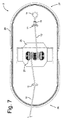
1つの曳航索10は、動力ウィンチ21から、上部構造体25の前方に位置するビット11の開口部まで延在し開口部を通過する。動力ウィンチ21は、好ましくは、ダブルウィンチであり、別の曳航索10(図7)は、動力ウィンチ21から延在し上部構造体25の後方に位置するビット12の開口部を通過する。 One towing line 10 extends from the power winch 21 to the opening of the bit 11 located in front of the superstructure 25 and passes through the opening. The power winch 21 is preferably a double winch, and another towline 10 (FIG. 7) extends from the power winch 21 and passes through an opening of a bit 12 located behind the superstructure 25.

ビット11、12は、曳航索10を案内して、正確に曳航索10の巻き上げおよび読み出しを行うために、確実に曳航索10が動力ウィンチ21に対して直角を成すようにする。曳航索10の自由端は、クレーン22の自由端の把持具によって保持される。いわゆる、もやい綱13は、曳航索10の自由端に取り付けられる。もやい綱13は、乗組員によって扱われ、被支援船舶1内の索道器を通過して被支援船舶1上のキャプスタンまで延びることができる軽い紐である。その後、キャプスタンを作動させることにより、重い曳航索10が索道器を通って船舶1の甲板まで引っ張られ得る。 Bits 11 and 12 guide the towline 10 to ensure that the towline 10 is at right angles to the power winch 21 in order to accurately wind and read the towline 10. The free end of the towline 10 is held by a gripper at the free end of the crane 22. The so-called Moyai rope 13 is attached to the free end of the towline 10. The Moyai rope 13 is a light string that is handled by the crew and can extend through the cableway in the supported vessel 1 to the capstan on the supported vessel 1. Then, by activating the capstan, the heavy towline 10 can be pulled through the cableway to the deck of the vessel 1.

上部構造体25は、レーダアンテナ31が設けられたレーダマスト30を支承する。さらに、レーダマスト30には、無線通信のための他のアンテナが設けられる。 The superstructure 25 supports a radar mast 30 provided with a radar antenna 31. Further, the radar mast 30 is provided with another antenna for wireless communication.

上部構造体25はさらに、クレーン22を支承する機能を果たす。この実施形態では、クレーン22は、ナックルブームクレーンであるが、任意の他の適切なタイプのクレーンまたはロボットアームを使用することも可能である。一実施形態では、クレーンアームには、放水銃(図示せず)が設けられる、または少なくとも放水銃をクレーンアームに固定する手段が設けられる。 The superstructure 25 further serves to support the crane 22. In this embodiment, the crane 22 is a knuckle boom crane, but any other suitable type of crane or robot arm can also be used. In one embodiment, the crane arm is provided with a water cannon (not shown), or at least a means of fixing the water cannon to the crane arm.

タグボート2上のクレーン22、動力ウィンチ21および他の機器は、油圧駆動式であり得る。この点に関して、タグボート2には、電子制御ユニット50の制御下で上記の消耗部品に対して加圧油圧作動液を供給する油圧ポンプまたはポンプ場が設けられる。 The crane 22, power winch 21 and other equipment on the tugboat 2 can be hydraulically driven. In this regard, the tugboat 2 is provided with a hydraulic pump or pumping station that supplies the pressurized hydraulic hydraulic fluid to the consumable parts under the control of the electronic control unit 50.

クレーン22は、好ましくは環状ベース部材35によって、タグボート2の垂直軸を中心として上部構造体25から枢動可能に吊り下げられる。クレーンアームの内側部分32の近位端は、ベース部材35にヒンジ連結され、内側部分32の遠位端は、ヒンジ34によってクレーンアームの外側部分33にヒンジ連結される。クレーンアームの外側部分33は、クレーンの届く範囲を広げるために伸縮自在である。 The crane 22 is pivotally suspended from the superstructure 25 about the vertical axis of the tugboat 2, preferably by an annular base member 35. The proximal end of the inner portion 32 of the crane arm is hinged to the base member 35, and the distal end of the inner portion 32 is hinged to the outer portion 33 of the crane arm by the hinge 34. The outer portion 33 of the crane arm is stretchable to increase the reach of the crane.

第1の油圧シリンダ36の近位端は、ベース部材35にヒンジ連結され、その遠位端は、外側部分33にヒンジ連結される。第1の油圧シリンダ36は、クレーンアームの上げ下げに使用され得る。クレーンアームは、図5では下降した休止位置にある状態で示されており、図6では上昇位置にある状態で示されているが、クレーン22は図6に示されているよりも高く上昇され得ることは理解されよう。第2の油圧シリンダ37は、伸縮自在の外側部分33の長さを調節するために、外側部分33に沿って延在する。クレーンアームは、図9では、外側部分が伸長位置にある状態で示されている。 The proximal end of the first hydraulic cylinder 36 is hinged to the base member 35 and its distal end is hinged to the outer portion 33. The first hydraulic cylinder 36 can be used for raising and lowering the crane arm. The crane arm is shown in the lowered resting position in FIG. 5 and in the raised position in FIG. 6, but the crane 22 is raised higher than shown in FIG. It will be understood to get. The second hydraulic cylinder 37 extends along the outer portion 33 in order to adjust the length of the stretchable outer portion 33. The crane arm is shown in FIG. 9 with the outer portion in the extended position.

治具42は、クレーンアームの自由遠位端に設けられる。一実施形態では、治具42は、把持具であるが、治具42は、交換可能な治具であり、ニーズに応じて異なる目的の治具、例えば、放水銃または電気コネクタ、フック、サーチライトのような治具に交換され得ることは理解されよう。この点に関して、タグボート2には、クレーンアームの自由遠位端に嵌合され得る治具アセンブリが設けられる。治具アセンブリは、タグボート2上のクレーン22の自由端が到達し得る位置に格納されるので、クレーンアームの自由端の端部の治具は、人間のオペレータが現実に存在しなくても変更可能である。 The jig 42 is provided at the free distal end of the crane arm. In one embodiment, the jig 42 is a gripping tool, but the jig 42 is a replaceable jig and has different purposes depending on the needs, such as a water cannon or an electric connector, a hook, a search. It will be understood that it can be replaced with a jig such as a light. In this regard, the tugboat 2 is provided with a jig assembly that can be fitted to the free distal end of the crane arm. Since the jig assembly is stored in a position on the tag boat 2 where the free end of the crane 22 can reach, the jig at the end of the free end of the crane arm can be modified without the actual presence of a human operator. It is possible.

クレーンアームには、クレーンアームの位置を示すセンサ(図示せず)が設けられる。一実施形態では、クレーンアームには、クレーンアームに作用する力/負荷を決定するためのセンサ(図示せず)が設けられる。 The crane arm is provided with a sensor (not shown) indicating the position of the crane arm. In one embodiment, the crane arm is provided with a sensor (not shown) for determining the force / load acting on the crane arm.

タグボート2には、クレーンアームが作動していないときにクレーンアームが載置され得る、すなわち、クレーンアームのパーツ位置を提供するためのクレーンアーム用の支持体38が設けられる。一実施形態では、支持体38は、前甲板上のビット11の一体部品であり、好ましくは、ヨークの形状を有する。タグボートには、前甲板上の1つの支持体38および後甲板上の1つの支持体39の2つの支持体が設けられ得るので、クレーンアームは、前方位置または後方位置の部品であり得る。支持体39は、好ましくは、ビット12の一体部品であり、ヨークのような形状である。支持体38、39は、クレーンアームの位置を調整するための基準点としての機能を果たす。一実施形態では、電子制御ユニット50は、支持体38または支持体39において規則的な時間間隔でクレーンアームを再補正するように構成される。 The tugboat 2 is provided with a support 38 for the crane arm to which the crane arm can be mounted when the crane arm is not operating, i.e., to provide a part position for the crane arm. In one embodiment, the support 38 is an integral part of the bit 11 on the front deck, preferably in the shape of a yoke. Since the tugboat may be provided with two supports, one support 38 on the front deck and one support 39 on the rear deck, the crane arm can be a front or rear position component. The support 39 is preferably an integral part of the bit 12 and has a yoke-like shape. The supports 38 and 39 serve as reference points for adjusting the position of the crane arm. In one embodiment, the electronic control unit 50 is configured to re-correct the crane arm at regular time intervals in the support 38 or support 39.

一実施形態では、曳航索10の自由遠位端には、アイスプライス14が設けられる。曳航索10は、好ましくは、強く、浮くのに十分に軽い合成材料で作られる。このようなタイプの曳航索は、市販されている。ブッシング15は、アイスプライス14に近い位置で曳航索10の周囲に設けられる。ブッシング15およびその機能について、さらに詳細に後述する。 In one embodiment, an ice price 14 is provided at the free distal end of the towline 10. The towline 10 is preferably made of a synthetic material that is strong and light enough to float. This type of towing line is commercially available. The bushing 15 is provided around the towline 10 at a position close to the ice price 14. The bushing 15 and its function will be described in more detail later.

図9では、クレーンは、伸長位置のクレーンアームの伸縮自在外側部分33で曳航索10の自由端を保持した状態で示されている。これは、被支援船舶1上の熟練船員に曳航索10の自由端を渡すのに適した位置である。 In FIG. 9, the crane is shown in a state where the free end of the towline 10 is held by the telescopic outer portion 33 of the crane arm in the extended position. This is a suitable position for passing the free end of the towline 10 to a skilled seafarer on the supported vessel 1.

図10は、タグボート2上の制御システムおよび設備のブロック図である。電子制御ユニット50は、測位システム(GPS)、モーションセンサ(または加速力を検知することができる動き参照センサ)、マイクロホンまたはマイクロホン装置、カメラ装置(好ましくはデジタルビデオカメラ)、RADAR31、LIDAR(レーザスキャナ)、ノズル角検出器、第1のRFIDリーダ、第2のRFIDリーダ、および曳航索力センサ、好ましくは、指向性力センサ、クレーン位置センサ、クレーン力センサを含むセンサアレイに接続される。電子制御ユニットはさらに、無線通信装置54、動力ウィンチ21、ノズルドライブ28を駆動するエンジンまたは駆動モータ、ノズルドライブ28(指向性制御角度センサ)、動き補正ユニットおよび把持具42を含むクレーン22に接続される。曳航索力センサは、動力ウィンチ21上のトルクセンサと各々のビット11、12の歪みゲージまたは同様の力測定装置との組み合わせであり得るので、電子制御ユニット50には、曳航索10に加わる引張力の大きさおよび曳航索10によって加えられる引張力の方向が伝えられる。 FIG. 10 is a block diagram of the control system and equipment on the tugboat 2. The electronic control unit 50 includes a positioning system (GPS), a motion sensor (or a motion reference sensor capable of detecting acceleration force), a microphone or a microphone device, a camera device (preferably a digital video camera), RADAR31, and LIDAR (laser scanner). ), Nozzle angle detector, first RFID reader, second RFID reader, and tow line force sensor, preferably connected to a sensor array including a directional force sensor, a crane position sensor, a crane force sensor. The electronic control unit is further connected to a crane 22 including a wireless communication device 54, a power winch 21, an engine or drive motor for driving the nozzle drive 28, a nozzle drive 28 (directional control angle sensor), a motion compensation unit and a grip 42. Will be done. Since the towing force sensor can be a combination of a torque sensor on the power winch 21 and a strain gauge of each bit 11 or 12 or a similar force measuring device, the electronic control unit 50 has a tension applied to the towing line 10. The magnitude of the force and the direction of the tensile force applied by the towline 10 are communicated.

一実施形態では、タグボート2には、好ましくはタグボート2の周囲領域全体を見渡せるように水平面において360°の視界を有する、光学センサ装置またはデジタルカメラ装置が設けられる。カメラ装置は、スペクトルの可視部内および/またはスペクトルの可視部の外側で動作し得る。電子制御ユニット50は、一実施形態では、カメラ装置の信号を制御センター200または遠隔制御ユニット150に無線で送信するように構成される。 In one embodiment, the tugboat 2 is preferably provided with an optical sensor device or digital camera device having a 360 ° field of view in a horizontal plane so as to overlook the entire perimeter of the tugboat 2. The camera device may operate within the visible part of the spectrum and / or outside the visible part of the spectrum. In one embodiment, the electronic control unit 50 is configured to wirelessly transmit the signal of the camera device to the control center 200 or the remote control unit 150.

電子制御ユニット50には、ナビゲーションモジュール、衝突防止モジュールおよび画像認識モジュールが設けられ、これらについては、以下により詳細に説明する。 The electronic control unit 50 is provided with a navigation module, a collision prevention module, and an image recognition module, which will be described in more detail below.

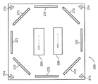
図26および図27に示されている制御センター200には、例えば、タグボート2上の通信装置54によって送信されたカメラ装置からの信号、および、言うまでもなく、通信装置54によって送信された任意の他の情報を受信するために、通信装置254が設けられる。制御センター200には、表示画面272であって、好ましくはリアルタイムで、さらに好ましくはリアルタイムでかつ表示画面272を360°の円形配列にして、制御センター内の人間のオペレータにカメラ装置の信号を表示するための表示画面272が設けられる。本発明の実施形態では、8つの表示画面272が円形配列で設けられているが、円形配列で8つより少ない数の表示画面を使用することもでき、また円形配列で8つより多い数の表示画面を使用することもできることは理解されよう。さらに、1つの全周囲にわたる表示画面を提供するために、代わりにプロジェクタなどが使用され得る。 The control center 200 shown in FIGS. 26 and 27 may include, for example, a signal from the camera device transmitted by the communication device 54 on the tugboat 2, and, needless to say, any other signal transmitted by the communication device 54. A communication device 254 is provided to receive the information of. The control center 200 has a display screen 272, preferably in real time, more preferably in real time, and the display screens 272 are arranged in a circular arrangement of 360 ° to display the signal of the camera device to a human operator in the control center. A display screen 272 is provided for this purpose. In the embodiment of the present invention, the eight display screens 272 are provided in a circular arrangement, but a smaller number of display screens in the circular arrangement can be used, and a larger number than eight in the circular arrangement can be used. It will be understood that the display screen can also be used. Further, a projector or the like may be used instead to provide one all-around display screen.

一実施形態では、例えば、タグボート2の針路における音の発生源(距離ならびに方向)および障害物に関する情報の両方に対して、拡張現実が表示画面277上に重ねられる。 In one embodiment, augmented reality is superimposed on the display screen 277, for example, for both sound sources (distance and direction) and information about obstacles in the course of the tugboat 2.

タグボート2には、音響センサ、好ましくは水平面において360°の領域の音を捕らえる指向性音響センサ装置が設けられる。一実施形態では、電子制御ユニット50は、指向性音響センサ装置からの信号を制御センター200または遠隔制御ユニット150に送信するように構成される。制御センター200内の電子制御ユニット250は、例えば、拡張現実によって、計器または表示画面上で、検出された音の発生源の方向および位置に関する情報を表示するように構成される。 The tugboat 2 is provided with an acoustic sensor, preferably a directional acoustic sensor device that captures sound in a region of 360 ° in a horizontal plane. In one embodiment, the electronic control unit 50 is configured to transmit a signal from the directional acoustic sensor device to the control center 200 or the remote control unit 150. The electronic control unit 250 in the control center 200 is configured to display information about the direction and position of the detected sound source on the instrument or display screen, for example by augmented reality.

制御センター200には、好ましくはリアルタイムで、さらに好ましくはリアルタイムでかつ空間的に、制御センター200内の人間のオペレータに、無線通信装置254を介して受信した光学センサ装置の信号を再生するために、トランスデューサ(ラウドスピーカ)274が設けられる。その結果、人間のオペレータは、検出された音の発生源の方向の印象を受け取る。 The control center 200 is preferably in real time, more preferably in real time and spatially, to reproduce the signal of the optical sensor device received via the wireless communication device 254 to the human operator in the control center 200. , Transducer (loud speaker) 274 is provided. As a result, the human operator receives an impression of the direction of the detected sound source.

さらに、制御センター200には、オペレータがタグボート2の操作を制御するための指示またはコマンドを入力できるようにする少なくとも1つの制御コンソール280が設けられる。制御コンソール280、無線通信装置254、ラウドスピーカ274および表示画面272は全て、電子制御ユニット250に接続される。電子制御ユニット250は、人間のオペレータから制御コンソール280を介して指示およびコマンドを受信し、これらの指示/コマンドを関与しているタグボート2に無線で送信するように構成される。電子制御ユニット250はさらに、表示画面272上に、ラウドスピーカ274を介して、および制御コンソール280内の計器および/またはディスプレイ上に、タグボートから受信した情報を再生するように構成される。 Further, the control center 200 is provided with at least one control console 280 that allows the operator to input instructions or commands for controlling the operation of the tugboat 2. The control console 280, the wireless communication device 254, the loudspeaker 274 and the display screen 272 are all connected to the electronic control unit 250. The electronic control unit 250 is configured to receive instructions and commands from a human operator via the control console 280 and wirelessly transmit these instructions / commands to the tugboat 2 involved. The electronic control unit 250 is further configured to reproduce information received from the tugboat on the display screen 272, via the loudspeaker 274, and on the instrument and / or display within the control console 280.

タグボート2上の測位システムは、一実施形態では、衛星型測位システム(例えば、GPS)であり、タグボート2は、一実施形態では、測位システムによって決定されたタグボートの地理的位置を制御センター200および/または遠隔制御ユニット150に無線で送信するように構成される。 The positioning system on the tugboat 2 is, in one embodiment, a satellite positioning system (eg, GPS), and in one embodiment, the tugboat 2 controls the geographical position of the tugboat determined by the positioning system with the control center 200 and / Or configured to transmit wirelessly to the remote control unit 150.

一実施形態では、電子制御ユニット50は、タグボート2を自律的に接岸させるように構成される。この点に関して、電子制御ユニット50は、係船場所または船体23の過負荷を回避するために、少なくとも1隻のタグボート2の付近の環境に的確に反応するように構成される。電子制御ユニットは、特に、加速度情報およびジャーク(加速度の変化、すなわち、時間に対する加速度の導関数)を含む動き参照センサからの信号を使用する。 In one embodiment, the electronic control unit 50 is configured to autonomously berth the tugboat 2. In this regard, the electronic control unit 50 is configured to respond appropriately to the environment in the vicinity of at least one tugboat 2 in order to avoid overloading the mooring site or hull 23. The electronic control unit specifically uses signals from motion reference sensors that include acceleration information and jerk (change in acceleration, i.e., derivative of acceleration over time).

一実施形態では、遠隔位置の制御センター200から少なくとも1隻のタグボート2を制御する方法は、タグボート2を配備することと、遠隔位置の制御センター200を配設することと、遠隔位置の制御センター200から少なくとも1隻のタグボート2に指示を無線で送信することと、タグボート2上で指示を無線で受信することと、タグボート2によって指示を実行することとを含む。 In one embodiment, the method of controlling at least one tugboat 2 from the remote control center 200 is to deploy the tugboat 2, dispose of the remote control center 200, and to control the remote control center. It includes transmitting an instruction wirelessly from 200 to at least one tugboat 2, receiving the instruction wirelessly on the tugboat 2, and executing the instruction by the tugboat 2.

一実施形態では、指示を無線で送信することは、特定の位置まで航行するようにとの指示をタグボート2に送信することと、タグボート2が指示を受信することと、タグボート2が特定の位置まで航行することとを含む。一実施形態では、該方法はさらに、好ましくはタグボート2が自律的に現在位置から特定の位置までナビゲートすることを含む、タグボート2が自律的に現在位置から特定の位置まで航行することを含む。 In one embodiment, transmitting the instruction wirelessly means transmitting an instruction to the tugboat 2 to navigate to a specific position, the tugboat 2 receiving the instruction, and the tugboat 2 at a specific position. Including sailing to. In one embodiment, the method further comprises the tugboat 2 autonomously navigating from the current position to the particular position, preferably comprising the tugboat 2 autonomously navigating from the current position to the particular position. ..

一実施形態では、指示を無線で送信することは、一定の距離を置いて被支援船舶1、好ましくは曳航索10に張力をかけずに曳航索10によってタグボート2に接続された被支援船舶を追尾するようにとの指示をタグボート2に送信することを含む。 In one embodiment, transmitting the instruction wirelessly means that the supported vessel 1 is connected to the tugboat 2 by the towline 10 without tensioning the towline 10, preferably the towline 10 at a certain distance. Includes sending instructions to the tugboat 2 to track.

一実施形態では、該方法は、遠隔制御ユニット150から少なくとも1隻のタグボート2に、タグボート2に接続された曳航索10の自由端を被支援船舶1上の受取人、特に、被支援船舶1上の特定の位置にいる受取人に渡すようにとの指示を送信することと、タグボート2が被支援船舶1の甲板上の乗組員に曳航索10の自由端を渡すためにクレーン22を使用して受取人に曳航索10の自由端を渡すこととを含む。 In one embodiment, the method comprises the remote control unit 150 to at least one tugboat 2 with the free end of the towline 10 connected to the tugboat 2 to the recipient on the supported vessel 1, in particular the supported vessel 1. The tugboat 2 uses the crane 22 to pass the free end of the towline 10 to the crew on the deck of the supported vessel 1 by sending instructions to pass it to the recipient at a specific position above. And passing the free end of the tugboat 10 to the recipient.

一実施形態では、該方法は、遠隔制御ユニット、例えば、パイロットによって操作される被支援船舶1上の携帯型遠隔制御ユニット150からタグボート2に、曳航索10を巻き上げる、または繰り出すようにとの指示を送信することと、タグボート10が動力ウィンチ21の作動によって曳航索10を繰り出すために巻き上げることとを含む。 In one embodiment, the method directs a remote control unit, eg, a portable remote control unit 150 on a supported vessel 1 operated by a pilot, to wind or unwind a towline 10 onto a tugboat 2. And the tugboat 10 is wound up to unwind the towline 10 by the operation of the power winch 21.

一実施形態では、該方法は、遠隔制御ユニット、例えば、パイロットによって操作される被支援船舶上の携帯型遠隔制御ユニット150から、被支援船舶1に対して所定の大きさおよび方向の推力を加えるためにタグボート2に対する所定の大きさおよび方向の推力コマンドのための指示を送信することと、タグボート2が被支援船舶1に指示された大きさおよび方向の推力を加えることとを含む。 In one embodiment, the method applies thrust of predetermined magnitude and direction to the supported vessel 1 from a remote control unit, eg, a portable remote control unit 150 on a supported vessel operated by a pilot. This includes sending instructions for thrust commands of predetermined magnitude and direction to the tugboat 2 and the tugboat 2 applying thrust of the indicated magnitude and direction to the supported vessel 1.

一実施形態では、該方法は、遠隔制御ユニット、例えば、パイロットによって操作される被支援船舶1上の携帯型遠隔制御ユニット150から、推力位置および任意で最適な推力角度のための指示を送信することと、タグボート2が指示された推力位置および最適な推力角度まで移動することとを含む。 In one embodiment, the method transmits instructions for a thrust position and optionally an optimal thrust angle from a remote control unit, eg, a portable remote control unit 150 on a supported vessel 1 operated by a pilot. This includes moving the tugboat 2 to the indicated thrust position and optimum thrust angle.

第1のRFIDリーダは、ビット11、12の各々に関連付けられ、第2のRFIDリーダは、クレーン22の自由端に関連付けられる。通信装置54により、電子制御ユニット50は情報を送受信することができる。 The first RFID reader is associated with each of the bits 11 and 12, and the second RFID reader is associated with the free end of the crane 22. The communication device 54 allows the electronic control unit 50 to transmit and receive information.

電子制御ユニット50は、動力ウィンチ21の動作、エンジン/駆動モータの動作(動力)、およびノズルドライブ28の動作(角度)を制御するように構成される。電子制御ユニット50はさらに、クレーン22の動作および把持具(グリッパ)42の動作を制御するように構成される。 The electronic control unit 50 is configured to control the operation of the power winch 21, the operation (power) of the engine / drive motor, and the operation (angle) of the nozzle drive 28. The electronic control unit 50 is further configured to control the operation of the crane 22 and the operation of the gripper (gripper) 42.

一実施形態では、カメラ、RADARならびにLIDAR、測位システム、利用可能であればソーナーからの信号は、通信装置54を介して制御センター200内の制御ユニット250またはパイロットの携帯型遠隔制御ユニット150に送信される。 In one embodiment, signals from the camera, RADAR and LIDAR, positioning system, and sonar, if available, are transmitted via the communication device 54 to the control unit 250 in the control center 200 or the pilot's portable remote control unit 150. Will be done.

クレーン22は、タグボート2の中央に取り付けられるので、前甲板および後甲板において曳航索10を操作することができる。さらに、中央位置に配置することにより、クレーン22は、接岸した状態で、また被支援船舶1上の熟練船員または他の乗組員に曳航索10を渡すときに、側面を超えることができる。 Since the crane 22 is attached to the center of the tugboat 2, the towing line 10 can be operated on the front deck and the rear deck. Further, by arranging in the central position, the crane 22 can cross the sides while berthing and when passing the towline 10 to a skilled seafarer or other crew member on the supported vessel 1.

電子制御ユニット50は、クレーン上の位置センサおよびモーションセンサおよび/またはタグボートの動き参照ユニットに応答して、またクレーン上のRFIDリーダに応答して、クレーンの動作を制御するように構成される。 The electronic control unit 50 is configured to control the movement of the crane in response to position sensors and motion sensors on the crane and / or motion reference units on the tugboat and in response to RFID readers on the crane.

一実施形態では、クレーン22には、動き補正ユニットが設けられる。一実施形態では、動き補正ユニットには、少なくとも2つの直交軸を中心として枢動し得る要素が設けられ、動き補正ユニットは、少なくとも2つの直交軸を中心として制御可能に要素を枢動させるためのアクチュエータを備える。一実施形態では、クレーン22は、動き補正プラットフォーム上に配置される。すなわち、動き補正ユニットは、動き補正プラットフォームによって形成される。動き補正プラットフォームは、電子制御ユニット50の制御の周囲でプラットフォームを支持する3つ以上の線形アクチュエータを備え得る。別の実施形態では、クレーン22の自由端の動きは、クレーン22のアクチュエータを使用することによって補正される。すなわち、動き補正ユニットは、クレーン22のアクチュエータによって形成される。一実施形態では、タグボート2の船首揺れは、クレーン22の回転によって少なくとも部分的に補正され、前後上下の揺れは、少なくとも部分的にクレーンアームの上げ下げおよび/または伸長収縮によって補正される。 In one embodiment, the crane 22 is provided with a motion compensation unit. In one embodiment, the motion correction unit is provided with an element capable of pivoting around at least two orthogonal axes, and the motion correction unit controlsably pivots the element around at least two orthogonal axes. Equipped with an actuator. In one embodiment, the crane 22 is placed on a motion compensation platform. That is, the motion correction unit is formed by the motion correction platform. The motion correction platform may include three or more linear actuators that support the platform around the control of the electronic control unit 50. In another embodiment, the movement of the free end of the crane 22 is corrected by using the actuator of the crane 22. That is, the motion correction unit is formed by the actuator of the crane 22. In one embodiment, the bow sway of the tugboat 2 is at least partially compensated by the rotation of the crane 22, and the front-back and up-down sway is at least partially compensated by the raising and lowering and / or extension and contraction of the crane arm.

モーションセンサ(動き参照ユニット)は、電子制御ユニット50に、タグボート2の動き、例えば、縦揺れ、横揺れおよび船首揺れ、より好ましくは、縦揺れ、横揺れ、船首揺れ、上下揺れ、前後揺れおよび左右揺れを含む動きを伝える。電子制御ユニット50は、クレーンアームの自由端の実質的にグローバル座標系に対する自由な動きを維持するために、タグボート2の移動を補正するように構成される。あるいは、電子制御ユニット50は、被支援船舶1上に搭載されているモーションセンサおよび/または位置センサの情報を受信し得、クレーンアームの自由端の被支援船舶1に対する実質的に自由な動きを維持し得る。一実施形態では、電子制御ユニット50は、タグボート2の実際の航行速度を無視するように構成される。すなわち、タグボートの航行速度によって生じる動きは、補正の際に考慮されない。したがって、クレーンアームの自由端は、タグボート2が被支援船舶1を追尾している間は安定し得る。タグボート2の動きを補正することによって、またはクレーンアームの自由端の被支援船舶1に対する自由な動きを維持することによって、クレーンアームが被支援船舶1の甲板上の乗組員に曳航索10を渡すときに、被支援船舶1の甲板上の乗組員がクレーンアームに取り付けられている曳航索10またはもやい綱13をずっと掴みやすくなる、または捕まえやすくなる。電子制御ユニット50は、陸への電気的接続を確立するときに、クレーンアームの自由端の動きを補正するように構成される。したがって、電子制御ユニット50は、有益な状況において、タグボートの動きによってもたらされるクレーンの自由端の動きを最小限に抑えるように構成される。クレーン22がビット11またはビット12におけるホームポジション(格納位置)から曳航索10の自由端を集めるのに使用されるとき、電子制御ユニット50は、参照用にタグボート2自身の座標系を使用する。電子制御ユニット50は、支持体38または支持体39上の休止位置を使用してクレーンアームの自由端の位置を再補正するように構成される。 The motion sensor (motion reference unit) is attached to the electronic control unit 50 to the movement of the tugboat 2, for example, pitching, rolling and bowing, more preferably pitching, rolling, bowing, up and down, back and forth and Communicate movements including left-right sway. The electronic control unit 50 is configured to compensate for the movement of the tugboat 2 in order to maintain substantially free movement of the free end of the crane arm with respect to a substantially global coordinate system. Alternatively, the electronic control unit 50 may receive information from a motion sensor and / or a position sensor mounted on the supported vessel 1 and allow the free end of the crane arm to move substantially freely with respect to the supported vessel 1. Can be maintained. In one embodiment, the electronic control unit 50 is configured to ignore the actual sailing speed of the tugboat 2. That is, the movement caused by the navigation speed of the tugboat is not taken into consideration in the correction. Therefore, the free end of the crane arm can be stable while the tugboat 2 is tracking the supported vessel 1. By compensating for the movement of the tugboat 2 or by maintaining the free movement of the free end of the crane arm with respect to the supported vessel 1, the crane arm passes the towline 10 to the crew on the deck of the supported vessel 1. Occasionally, it becomes much easier or easier for the crew on the deck of the supported vessel 1 to grab or catch the tugboat 10 or the fast rope 13 attached to the crane arm. The electronic control unit 50 is configured to compensate for the movement of the free end of the crane arm when establishing an electrical connection to land. Therefore, the electronic control unit 50 is configured to minimize the free end movement of the crane caused by the movement of the tugboat in beneficial situations. When the crane 22 is used to collect the free ends of the towline 10 from the home position in bit 11 or bit 12, the electronic control unit 50 uses the tugboat 2's own coordinate system for reference. The electronic control unit 50 is configured to re-correct the position of the free end of the crane arm using the rest position on the support 38 or support 39.

電子制御ユニット50には、電子制御ユニット52がタグボート2を自律的に現在位置から受信指示位置まで、例えば、支援を必要としている船舶1の近くの位置までナビゲートすることを可能にするナビゲーションモジュールが設けられる。ナビゲーションモジュールは、タグボート2の安全なナビゲートに必要な海図を含み、タグボート2用のナビゲーションシステムを形成する。ナビゲーションモジュールにより、電子制御ユニット50は、タグボート2を係船位置から目標位置まで、例えば、動員位置まで、すなわち、船舶1の操縦を支援するようにタグボート2を配備すべき位置まで、ナビゲートすることができる。さらに、ナビゲーションモジュールにより、電子制御ユニットは、動員位置から係船位置まで戻るようにタグボートをナビゲートすることができる。したがって、電子制御ユニット50は、無線通信装置54を介して指示を受信した時に、タグボート2を係船位置から動員位置まで、および動員位置から係船位置まで自律的に航行させる。タグボート2の針路における障害物との衝突は、電子制御ユニットが衝突防止モジュールを配備することによって回避される。これに関して、以下でさらに詳細に説明する。衝突防止ユニットの支援によって、電子制御ユニット50は、別の船舶、陸地、橋杙または浅海域のような物体との衝突を回避するために、必要に応じて回避行動を取る。 The electronic control unit 50 is a navigation module that allows the electronic control unit 52 to autonomously navigate the tugboat 2 from the current position to the receive instruction position, for example, to a position near the vessel 1 in need of assistance. Is provided. The navigation module contains nautical charts necessary for safe navigation of the tugboat 2 and forms a navigation system for the tugboat 2. With the navigation module, the electronic control unit 50 navigates the tugboat 2 from the mooring position to the target position, for example, to the mobilization position, i.e., to the position where the tugboat 2 should be deployed to assist the maneuvering of the vessel 1. Can be done. In addition, the navigation module allows the electronic control unit to navigate the tugboat back from the mobilization position to the mooring position. Therefore, when the electronic control unit 50 receives an instruction via the wireless communication device 54, the tugboat 2 autonomously navigates from the mooring position to the mobilization position and from the mobilization position to the mooring position. Collisions with obstacles in the course of the tugboat 2 are avoided by the electronic control unit deploying a collision prevention module. This will be described in more detail below. With the support of the anti-collision unit, the electronic control unit 50 takes evasive action as necessary to avoid collisions with objects such as other vessels, land, bridges or shallow waters.

ナビゲーションシステムは、好ましくは、COLREG条約の意図の範囲内の全てのシナリオにおいてタグボート2を操縦するように構成された自律ナビゲーションシステムである。COLREG条約に準拠したアルゴリズムは、電子制御ユニット50内に記憶されるので、電子制御ユニット50は、全てのシナリオにおいて安全にナビゲートするために、必要な針路修正を行うことができる。 The navigation system is preferably an autonomous navigation system configured to steer the tugboat 2 in all scenarios within the intent of the COLREG Convention. Since the algorithm conforming to the COLREG Convention is stored in the electronic control unit 50, the electronic control unit 50 can make necessary course corrections for safe navigation in all scenarios.

衝突防止モジュールは、例えば、COLREG(海上における衝突の予防のための国際規約に関する条約、1972)のような衝突予防に関する規制情報を含み、規則に従った回避行動を取る。衝突防止モジュールは、電子制御ユニット2がいつどの回避行動を取るべきかを決定するのを可能にする。 The collision prevention module contains regulatory information on collision prevention, such as COLREG (International Regulations for Preventing Collisions at Sea, 1972), and takes evasive action in accordance with the rules. The anti-collision module allows the electronic control unit 2 to determine when and which avoidance action should be taken.

さらに、電子制御ユニット50には、電子制御ユニット50が船体3の側面のストロングポイントおよび被支援船舶1を示す画像を認識できるようにする画像認識モジュールが設けられる。一実施形態では、電子制御ユニットは、画像認識モジュールの助けを借りて、甲板上の乗組員、すなわち、曳航索10を受け取る準備ができた被支援船舶を認識することができる。 Further, the electronic control unit 50 is provided with an image recognition module that enables the electronic control unit 50 to recognize an image showing a strong point on the side surface of the hull 3 and the supported ship 1. In one embodiment, the electronic control unit can recognize a crew member on the deck, i.e., a supported vessel ready to receive the towline 10, with the help of an image recognition module.

図11および図12は、把持具42の第1の実施形態の2つの側面をより詳細に示した図である。把持具42は、ヒンジピン78で互いに枢動可能に接続された2つのミラー対称部品71を備える。線ばね75は、2つの部品71を一緒に付勢する。2つの部品71の一端は、曳航索10を係合する、または曳航索10上のブッシング15を受容するためのV字形凹部を形成する。V字形凹部79の表面が曳航索10またはブッシング15と接触することで、洗濯ばさみが物干しロープに対して付勢される形と同じように、線ばね75の力に逆らって2つの部品71が互いに離れてヒンジピン78を中心として枢動するように付勢力が生じる。把持具42が曳航索10またはブッシング15を挟んだときに、曳航索10またはブッシング15は、図11に示されているように、各々の部品71の2つの半円筒状凹部によって形成された実質的に円筒状凹部72内に受容される。実質的に円筒状凹部72のV字形凹部79に最も近い部分は、線ばね75の力に逆らって円筒状凹部72から曳航索10を引き抜きやすくする実質的にV字形の断面を成すような形状にされる。 11 and 12 are views showing in more detail the two aspects of the first embodiment of the grip 42. The grip 42 comprises two mirror symmetric components 71 pivotally connected to each other by hinge pins 78. The wire spring 75 urges the two parts 71 together. One end of the two components 71 forms a V-shaped recess for engaging the towline 10 or receiving a bushing 15 on the towline 10. Two parts against the force of the wire spring 75, similar to the way clothespins are urged against the clothesline by contacting the surface of the V-shaped recess 79 with the towline 10 or bushing 15. An urging force is generated so that the 71 are separated from each other and pivotally centered on the hinge pin 78. When the gripper 42 sandwiches the towline 10 or bushing 15, the towline 10 or bushing 15 is substantially formed by the two semi-cylindrical recesses of each part 71, as shown in FIG. Is received in the cylindrical recess 72. The portion of the cylindrical recess 72 closest to the V-shaped recess 79 has a substantially V-shaped cross section that makes it easier to pull out the towline 10 from the cylindrical recess 72 against the force of the wire spring 75. Be made.

2つの部品71のヒンジピン7を中心とした枢動運動は、電磁制御式、空気圧制御式、または油圧制御式の係止ピン73の作用によって防止され得る。電気式、空気圧式、または油圧式のアクチュエータ74は、係止ピン73が2つの部品71間の円筒状凹部77まで前進しない後退位置と、係止ピンが円筒状凹部77まで前進する前進位置(図12)との間で係止ピン73の位置を制御する。凹部77は、部品71間の円筒状凹部72と反対側のヒンジピン78の側に配置される。係止ピン72は、凹部77まで前進すると、部品71が互いに離れることを防止するので、大きな力が曳航索10に加えられた場合でも曳航索10は実質的に円筒状凹部72内で保持され得る。 The pivotal movement of the two components 71 around the hinge pin 7 can be prevented by the action of an electromagnetically controlled, pneumatically controlled, or hydraulically controlled locking pin 73. The electric, pneumatic, or hydraulic actuator 74 has a retracted position in which the locking pin 73 does not advance to the cylindrical recess 77 between the two components 71, and a forward position in which the locking pin advances to the cylindrical recess 77 ( The position of the locking pin 73 is controlled to and from FIG. 12). The recess 77 is arranged on the side of the hinge pin 78 opposite the cylindrical recess 72 between the parts 71. The locking pin 72 prevents the parts 71 from separating from each other when advanced to the recess 77, so that the towline 10 is substantially held in the cylindrical recess 72 even when a large force is applied to the towline 10. obtain.

図13および図14は、把持具42の第2の実施形態を示しており、ばねを設ける必要がなく、ヒンジピン78を中心とした2つの部品71の運動は1つまたは2つのダブルの空気圧シリンダまたは油圧シリンダ80の作用によって制御されるという点を除けば、第1の実施形態と同様である。凹部72は、把持具42が能動的に開くことができるため、ばねの力に逆らって曳航索を引き抜く必要がないので、円筒状であり得る。1つまたは2つの空気圧シリンダまたは油圧シリンダ80は、部品71の上方(図13および図14の向きで示されている上方の)先端間に延在し、把持具を開くために引張力を加えて曳航索10を受容または解放し、把持具42を閉じるために押す力を加えて、円筒状凹部72内の曳航索10の有無に関係なく把持具42を閉じた状態で維持する。空気圧シリンダまたは油圧シリンダ80の動作は、電子制御ユニット50によって制御される。 13 and 14 show a second embodiment of the grip 42, without the need for a spring, the movement of the two parts 71 around the hinge pin 78 is one or two double pneumatic cylinders. Alternatively, it is the same as the first embodiment except that it is controlled by the action of the hydraulic cylinder 80. The recess 72 may be cylindrical as the grip 42 can be actively opened and therefore the towline does not need to be pulled out against the force of the spring. One or two pneumatic or hydraulic cylinders 80 extend between the upper tips (upper, shown in the orientations of FIGS. 13 and 14) of the part 71 and apply tensile force to open the grip. The towing line 10 is received or released, and a pushing force is applied to close the gripping tool 42 to keep the gripping tool 42 closed regardless of the presence or absence of the towing line 10 in the cylindrical recess 72. The operation of the pneumatic cylinder or hydraulic cylinder 80 is controlled by the electronic control unit 50.

ヒンジピン78は、把持具42から、クレーンの自由端から把持具42を吊り下げる働きをするヨーク84の対向するアーム内の凹部まで延在する。第1の実施形態の把持具42は、同様にヨークによってクレーンの自由端から吊り下げられ得る。 The hinge pin 78 extends from the grip 42 to a recess in the opposite arm of the yoke 84 that serves to suspend the grip 42 from the free end of the crane. The grip 42 of the first embodiment can also be suspended from the free end of the crane by a yoke.

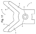
図15は、曳航索10の一実施形態の遠位部分を示す。曳航索10の自由遠位端には、堅硬なアイスプライス14が設けられる。堅硬なアイスプライスは、エンドストップを形成する。構造上の剛性を付与するために、軽金属または頑丈な弾性プラスチックのリング42がアイの中に配置される。堅硬なアイスプライス14によって形成されたエンドストップは、ビット11、12内の開口部18(図17)を通過することができないような大きさおよび形状であるので、堅硬なアイスプライス14はエンドストップを形成する。このことにより、動力ウィンチ21は、エンドストップがビット11、12に突き当たるまで完全に曳航索10を巻き上げることができる。 FIG. 15 shows the distal portion of one embodiment of the towline 10. A rigid ice price 14 is provided at the free distal end of the towline 10. A solid ice price forms an end stop. A light metal or sturdy elastic plastic ring 42 is placed in the eye to provide structural rigidity. The rigid ice price 14 is an end stop because the end stop formed by the rigid ice price 14 is such a size and shape that it cannot pass through the opening 18 (FIG. 17) in the bits 11 and 12. To form. This allows the power winch 21 to completely wind up the towline 10 until the end stop hits the bits 11 and 12.

一実施形態では、動力ウィンチ21には、電子制御ユニット50に結合される回転位置センサ(図示せず)が設けられ、回転位置センサによって、電子制御ユニット50に、繰り出される曳航索10の長さがおおまかに知らされる。 In one embodiment, the power winch 21 is provided with a rotation position sensor (not shown) coupled to the electronic control unit 50, and the length of the towing line 10 delivered to the electronic control unit 50 by the rotation position sensor. Is roughly informed.

一実施形態では、動力ウィンチ21には、力またはトルクセンサが設けられ、電子制御ユニット50は、力またはトルクセンサからの信号を使用して、巻き上げのときに曳航索に加えられる力を制限するように構成される。電子制御ユニット50は、好ましくは、エンドストップに向かって牽引するときに動力ウィンチ21によって曳航索10に加えられる力を制限するように構成される。 In one embodiment, the power winch 21 is provided with a force or torque sensor, and the electronic control unit 50 uses a force or signal from the torque sensor to limit the force applied to the towline during hoisting. It is configured as follows. The electronic control unit 50 is preferably configured to limit the force applied to the towline 10 by the power winch 21 when towing towards the end stop.

電子制御ユニット50が動力ウィンチ21に曳航索10を巻き上げるように指示したときに、曳航索10がホームポジション(部品位置)にあるため、動力ウィンチ21上の力センサからの信号の急増が電子制御ユニット50に曳航索10の巻き上げを停止するように伝える。 When the electronic control unit 50 instructs the power winch 21 to wind up the tow line 10, since the tow line 10 is in the home position (part position), the sudden increase in the signal from the force sensor on the power winch 21 is electronically controlled. Tell unit 50 to stop hoisting the towline 10.

一実施形態では、曳航索10は、その自由端に、または自由端の近くに、第1のRFIDタグ90が設けられる。第1のRFIDタグは、好ましくは、パッシブRFID90タグ90である。タグボート2には、一実施形態では、第1のRFIDリーダ、好ましくは、アクティブRFIDリーダが設けられ、第1のRFIDリーダは、曳航索10の自由端がビット11またはビット12のごく近くにあるときに、すなわち、ホームポジションまたは部品位置にあるときに、RFIDリーダが第1のRFIDタグ90を検出するように配置される。好ましくは、各々のビット11、12の近くに1つずつ、2つの第1のRFIDリーダが設けられる。第1のRFIDタグ90は、好ましくは、パッシブタグであり、第1のRFIDリーダは、好ましくは、アクティブRFIDリーダである。 In one embodiment, the towline 10 is provided with a first RFID tag 90 at or near its free end. The first RFID tag is preferably a passive RFID 90 tag 90. In one embodiment, the tugboat 2 is provided with a first RFID reader, preferably an active RFID reader, in which the free end of the towline 10 is very close to bit 11 or bit 12. Occasionally, ie, when in the home position or component position, the RFID reader is arranged to detect the first RFID tag 90. Preferably, two first RFID readers are provided, one near each of the bits 11 and 12. The first RFID tag 90 is preferably a passive tag and the first RFID reader is preferably an active RFID reader.

第1のRFIDタグ90は、一実施形態では、堅硬なアイスプライス14内または堅硬なアイスプライス14の位置に設けられる。別の実施形態では、第1のRFIDタグ90は、エンドストップ15の位置に設けられる。 In one embodiment, the first RFID tag 90 is provided in the rigid ice price 14 or at the position of the rigid ice price 14. In another embodiment, the first RFID tag 90 is provided at the position of the end stop 15.

第1のRFIDリーダは、エンドストップ15または堅硬なアイスプライス14がビット11またはビット12のごく近くにあるときに、RFIDリーダが第1のRFIDタグ90を検出するように配置される。 The first RFID reader is arranged such that the RFID reader detects the first RFID tag 90 when the end stop 15 or the rigid ice price 14 is in close proximity to the bit 11 or bit 12.

電子制御ユニット50は、第1のRFIDリーダに結合され、電子制御ユニット50は、巻き上げ動作の間に、第1のRFIDリーダがビット11またはビット12における第1のRFIDタグ90の存在を検出したときに、動力ウィンチ21の動作を終了させるように構成される。 The electronic control unit 50 is coupled to the first RFID reader, and the electronic control unit 50 detects the presence of the first RFID tag 90 in bit 11 or bit 12 by the first RFID reader during the winding operation. Occasionally, it is configured to terminate the operation of the power winch 21.

一実施形態では、クレーン22には、第2のRFIDリーダ、好ましくはアクティブRFIDリーダが設けられる。第2のRFIDリーダは、把持具42のごく近くに配置されているので、第2のRFIDリーダは、把持具がアイスプライス14の位置またはアイスプライス14の近くで曳航索を掴むのに適切な位置にあるときに、第1のRFIDタグを検出する。したがって、電子制御ユニット50に、把持具42が曳航索10の自由端の近くにある時点が伝えられる。 In one embodiment, the crane 22 is provided with a second RFID reader, preferably an active RFID reader. Since the second RFID reader is located very close to the grip 42, the second RFID reader is suitable for the grip to grab the towline at or near the ice price 14. Detects the first RFID tag when in position. Therefore, the electronic control unit 50 is informed of the time point when the gripping tool 42 is near the free end of the towline 10.

一実施形態では、曳航索10には、曳航索10の長さに沿って、間隔を置いて、好ましくは、規則的な距離間隔を置いて、複数のRFIDタグ90が設けられる。第1のRFIDリーダは、曳航索10の巻き上げまたは繰り出しの間に、複数のRFIDタグのうちのRFIDタグ90がビット11、12内の開口部18(図17)を通過したときにRFIDタグ90を記録するように配置される。各々のRFID90は、個々の情報を記憶し得るので、試験制御ユニット50は、特定のRFIDタグ90が第1のRFIDリーダを通過したときに、どのくらいの時系列リンクが巻き上げまたは繰り出しを行ったかを正確に判断することができる。したがって、有能な電子制御ユニット50は、第1のRFIDリーダからの信号を使用して、繰り出される曳航索10の長さを非常に正確に制御するように構成され、曳航索10の破損または曳航索10の張力不足による動力ウィンチ21とビット11またはビット12との間の曳航索10の積み重なりのようなエラーを判断することができる。 In one embodiment, the towline 10 is provided with a plurality of RFID tags 90 at intervals, preferably at regular distance intervals, along the length of the towline 10. The first RFID reader determines the RFID tag 90 when the RFID tag 90 of the plurality of RFID tags passes through the opening 18 (FIG. 17) in the bits 11 and 12 during the winding or unwinding of the tow line 10. Is arranged to record. Since each RFID 90 can store individual information, the test control unit 50 determines how many time series links rolled up or unwound when a particular RFID tag 90 passed through the first RFID reader. It can be judged accurately. Therefore, the competent electronic control unit 50 is configured to use the signal from the first RFID reader to control the length of the towline 10 to be unwound very accurately, and the towline 10 is damaged or damaged. It is possible to determine an error such as the stacking of the towline 10 between the power winch 21 and the bit 11 or the bit 12 due to insufficient tension of the towline 10.

別の実施形態では、曳航索10には、曳航索10の長さに沿って間隔を置いて、好ましくは規則的な距離間隔を置いて配置された複数の光学タグが設けられ、動力ウィンチ21の位置、ビット11、12の位置、または動力ウィンチ21とビット11、12との間で電子制御ユニット50に接続された光学リーダが、繰り出される曳航索10の長さを決定するために光学タグを検出する。 In another embodiment, the towline 10 is provided with a plurality of optical tags spaced along the length of the towed line 10, preferably spaced at regular distances, and the power winch 21. The position, the position of the bits 11 and 12, or the optical reader connected to the electronic control unit 50 between the power winch 21 and the bits 11 and 12 determines the length of the tow line 10 to be unwound. Is detected.

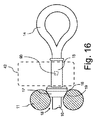
図16は、柔軟なアイスプライス14を有する曳航索10の別の実施形態を示す。好ましくは軽金属または頑丈な弾性プラスチックで形成されたブッシング15は、曳航索10に配置され、柔軟なアイスプライス14の近くで曳航索10に固定される。したがって、曳航索10は、ブッシング15を通って延在する。ブッシング15は、柔軟なアイスプライス14に最も近い端部にフランジが設けられ、その反対側の端部にエンドストップ17が設けられる。ブッシング15の主要延長部は、把持具42(図16には破線で示されている)の把持対象としての機能を果たす。ブッシング15の主要延長部の長さは、把持具42がブッシング15の周囲を掴むことができるのに十分な長さである。エンドストップ17は、ビット11、12内の対応円錐座19に係合するための係合面としての機能を果たす円錐台を備える(図16および図17)。ビット11、12内の開口部18は、曳航索10が通過することができる大きさであるが、エンドストップ17が開口部18を通過することができないほどの小さい直径を有する。図16に示されているように、動力ウィンチ21が曳航索10を引いて巻き上げるときに、エンドストップ17はビット11、12および円錐座表面19と当接し、動力ウィンチ21によって維持される曳航索10の張力により、確実にブッシング15が常にビット11、12から同じ方向に延在するようになる。したがって、曳航索10が完全に巻き上げられたときに、ブッシング15の位置および向きがわかり、常に同じである。このことにより、把持具42はブッシング15の正確な位置を認識するので、大幅に把持具42でブッシング15を掴みやすくなる。 FIG. 16 shows another embodiment of the towline 10 having a flexible ice price 14. The bushing 15, preferably made of light metal or sturdy elastic plastic, is placed on the towline 10 and secured to the towline 10 near the flexible ice price 14. Therefore, the towline 10 extends through the bushing 15. The bushing 15 is provided with a flange at the end closest to the flexible ice price 14, and an end stop 17 at the opposite end. The main extension of the bushing 15 serves as a gripping object for the gripping tool 42 (shown by the dashed line in FIG. 16). The length of the main extension of the bushing 15 is long enough for the gripper 42 to grip around the bushing 15. The end stop 17 comprises a truncated cone that serves as an engaging surface for engaging the corresponding cones 19 in the bits 11 and 12 (FIGS. 16 and 17). The openings 18 in the bits 11 and 12 are large enough for the towline 10 to pass through, but have a diameter so small that the end stop 17 cannot pass through the openings 18. As shown in FIG. 16, when the power winch 21 pulls and winds up the towline 10, the end stop 17 comes into contact with the bits 11 and 12 and the conical seat surface 19 and is maintained by the power winch 21. The tension of 10 ensures that the bushing 15 always extends in the same direction from the bits 11 and 12. Therefore, when the towline 10 is completely wound up, the position and orientation of the bushing 15 is known and is always the same. As a result, since the gripping tool 42 recognizes the exact position of the bushing 15, it becomes much easier for the gripping tool 42 to grip the bushing 15.

支持体38は、好ましくは、ビット11、12の一体部品であり、クレーンアームを支持体38の中心に向けて案内するための2つの先細案内部43を形成する2つの羽根部44で形成されたヨーク形状支持部を備える。ヨークの支持面は、好ましくは、休止(格納)位置で支持面に載置されるクレーンアームの角度と一致するように傾斜している。 The support 38 is preferably an integral part of the bits 11 and 12 and is formed by two blades 44 forming two tapered guides 43 for guiding the crane arm toward the center of the support 38. It is equipped with a crane-shaped support. The support surface of the yoke is preferably tilted to match the angle of the crane arm mounted on the support surface in the resting (retracted) position.

一実施形態では、電子制御ユニット50に、クレーンアームの操作によって任意の位置からビット11、12に近い第1の参照位置まで把持具42を移動させる指示が出される。電子制御ユニット50に、把持具52が第1の参照位置に到達したときに曳航索10を掴むように把持具を作動させる指示が出される。さらに、電子制御ユニット50に、クレーンアームの自由端の把持具42を第1の参照位置から指示位置まで移動させる指示が出され、指示位置は、好ましくは、遠隔送信器(例えば、パイロットの遠隔制御ユニット150)から通信装置54によって無線で受信される位置である。電子制御ユニット50はさらに、クレーンアームが所望の位置に向けて曳航索の自由端を移動させるのと同時に、曳航索10を繰り出すように構成される。したがって、クレーン22が曳航索10の自由端を格納位置から所望位置まで移動させる間、曳航索10上で一定の張力が維持され得る。 In one embodiment, the electronic control unit 50 is instructed to move the gripping tool 42 from an arbitrary position to a first reference position close to the bits 11 and 12 by operating the crane arm. The electronic control unit 50 is instructed to operate the gripping tool so as to grip the towing line 10 when the gripping tool 52 reaches the first reference position. Further, the electronic control unit 50 is instructed to move the gripping tool 42 at the free end of the crane arm from the first reference position to the indicated position, and the indicated position is preferably a remote transmitter (eg, remote of the pilot). It is a position that is wirelessly received from the control unit 150) by the communication device 54. The electronic control unit 50 is further configured to deliver the towline 10 at the same time that the crane arm moves the free end of the towline toward a desired position. Therefore, a constant tension can be maintained on the towline 10 while the crane 22 moves the free end of the towline 10 from the retracted position to the desired position.

電子制御ユニット50は、把持具42が指示位置に到達したときに、および/または把持具42を停止させる/開くためにタグボート2上の投薬装置54が遠隔送信器から確認を受信したときに、すなわち、被支援船舶1の甲板上の乗組員が曳航索10を受け取ったときに、曳航索10を解放するために把持具42を停止させる/開くように構成される。パイロットの遠隔制御ユニット150には、把持具42が曳航索を解放することができるように、曳航索10が渡されたことを示す入力手段が設けられる。あるいは、乗組員は、曳航索10が受け取られたとの肯定応答を送信するために、自分用の携帯型無線通信ユニットを有し得る。 The electronic control unit 50 receives confirmation from the remote transmitter when the grip 42 reaches the indicated position and / or when the dosing device 54 on the tugboat 2 receives confirmation from the remote transmitter to stop / open the grip 42. That is, when the crew member on the deck of the supported vessel 1 receives the tugboat 10, the gripping tool 42 is stopped / opened in order to release the tugboat 10. The pilot's remote control unit 150 is provided with input means indicating that the towline 10 has been passed so that the gripping tool 42 can release the towline. Alternatively, the crew may have their own portable radio communication unit to transmit an acknowledgment that the towline 10 has been received.

一実施形態では、タグボート2には、タグボートに対する座標系においてクレーンまたはロボットアームを補正するための第2の基準点が設けられ、第2の基準点は、支持体38または支持体39のようなタグボート上に設けられた固定構造物であり得る。電子制御ユニット50は、所定の時間間隔で第2の基準点においてクレーン22を再補正するように構成される。 In one embodiment, the tugboat 2 is provided with a second reference point for correcting the crane or robot arm in the coordinate system with respect to the tugboat, the second reference point being such as support 38 or support 39. It can be a fixed structure provided on a tugboat. The electronic control unit 50 is configured to re-correct the crane 22 at a second reference point at predetermined time intervals.

電子制御ユニット50は、通信装置54を介して指示を受信したときに、すなわち、曳航索10が受け取られて被支援船舶1から解放されたときに、動力ウィンチ21を作動させることによって曳航索10を巻き上げるように構成される。曳航索10を巻き上げるようにとの指示は、例えば、支援操作が完了し、システム船舶1上の乗組員がシステム船舶1上のボラードまたはキャプスタンから曳航索10を取り外したとパイロットが判断したときに、遠隔制御ユニット150から出され得る。関与している乗組員がタグボート2に、曳航索10が被支援船舶1から解放され、タグボート2によって巻き上げられ得ることを無線で通信することができるように、被支援船舶1の甲板上で曳航索10を操作する乗組員によって、追加の遠隔制御ユニット(図示せず)が携行される場合がある。甲板上で曳航索を操作する乗組員が使用するためのこの追加の遠隔制御ユニットは、一実施形態では、ビーコンXと併用される。 The electronic control unit 50 operates the power winch 21 when the instruction is received via the communication device 54, that is, when the towline 10 is received and released from the supported vessel 1. Is configured to wind up. The instruction to wind up the towline 10 is given, for example, when the pilot determines that the support operation has been completed and the crew on the system vessel 1 has removed the towline 10 from the bollard or capstan on the system vessel 1. , Can be taken out of the remote control unit 150. Towed on the deck of the supported vessel 1 so that the crew involved can wirelessly communicate to the tugboat 2 that the towline 10 is released from the supported vessel 1 and can be hoisted by the tugboat 2. An additional remote control unit (not shown) may be carried by the crew operating the rope 10. This additional remote control unit for use by the crew operating the towline on the deck is, in one embodiment, used in conjunction with Beacon X.

電子制御ユニット50は、巻き上げ操作の間、動力ウィンチ21上の回転位置センサからの信号を使用して、利用可能で有れば、第1のRFIDリーダまたは光学リーダからの信号を使用して、繰り出される曳航索10の長さを追跡する。 The electronic control unit 50 uses the signal from the rotational position sensor on the power winch 21 during the hoisting operation and, if available, the signal from the first RFID reader or optical reader. Track the length of the towline 10 to be unwound.

電子制御ユニット50は、ロケーション装置54を介して指示を受信したときに、動力ウィンチ21を作動させることによって曳航索10を繰り出すように構成されるので、タグボート2は、被支援船舶1から最適な距離にある最適な所望の推力位置を推測することができる。曳航索10を繰り出すようにとの指示は、パイロットの遠隔制御ユニット150によって出され得る。 Since the electronic control unit 50 is configured to pay out the towing line 10 by operating the power winch 21 when receiving an instruction via the location device 54, the tugboat 2 is optimal from the supported vessel 1. The optimum desired thrust position at a distance can be inferred. Instructions to unwind the towline 10 may be issued by the pilot's remote control unit 150.

一実施形態では、クレーンアームには、デジタルカメラが設けられ、画像認識ユニットは、被支援船舶1の船体上の図形模様を認識する、または被支援船舶1の甲板上の乗組員を認識する、または被支援船舶1上の索道器を認識する、または入渠位置もしくは係船位置を認識するように構成される。一実施形態では、カメラからの信号は、通信装置54を介して遠隔位置の受信者(例えば、制御センター200)に無線で送信される。 In one embodiment, the crane arm is provided with a digital camera, and the image recognition unit recognizes a graphic pattern on the hull of the supported ship 1 or recognizes a crew member on the deck of the supported ship 1. Alternatively, it is configured to recognize the rope device on the supported vessel 1 or to recognize the docking position or the mooring position. In one embodiment, the signal from the camera is wirelessly transmitted to a remote receiver (eg, control center 200) via the communication device 54.

一実施形態では、タグボート2には、被支援船舶1上のビーコンX(図3)の位置を検出するためのセンサ(図示せず)が設けられる。被支援船舶1上のビーコンXは、GPSビーコン、レーダービーコン、または被支援船舶1の位置を容易にかつ正確に決定することができる他の適切なビーコンであり得る。ビーコンXは、一実施形態では、曳航索10を受け取るべき被支援船舶1に乗船している乗組員によって携行される。したがって、電子制御ユニット50には、曳航索10が被支援船舶1に渡すべき正確な位置が伝えられる。ビーコンXは、1つまたは複数のビーコンXおよび遠隔制御ユニット150を含むパッケージの一部であり得る。このパッケージは、パイロットによって被支援船舶1に乗船した状態で携行される。パイロットは、遠隔制御ユニットを操作し、パイロットは、曳航索(単数または複数)10を受け取るべき個々の乗組員に単数または複数のビーコンXを配布する。一実施形態では、タグボート2には、曳航索10を受け取る準備ができている乗組員の正確な位置で曳航索10を渡しやすくするために、ビーコンXの有無および正確な位置を検出するための専用のセンサが設けられる。 In one embodiment, the tugboat 2 is provided with a sensor (not shown) for detecting the position of the beacon X (FIG. 3) on the supported vessel 1. The beacon X on the supported vessel 1 can be a GPS beacon, a radar beacon, or any other suitable beacon that can easily and accurately determine the position of the supported vessel 1. In one embodiment, the beacon X is carried by a crew member aboard the supported vessel 1 to receive the towline 10. Therefore, the electronic control unit 50 is informed of the exact position that the towline 10 should pass to the supported vessel 1. Beacon X may be part of a package that includes one or more Beacons X and the remote control unit 150. This package is carried by the pilot on board the supported vessel 1. The pilot operates the remote control unit, and the pilot distributes the single or multiple Beacon X to the individual crew members who should receive the towline (s) 10. In one embodiment, the tugboat 2 is used to detect the presence and absence of Beacon X and its exact location to facilitate passing the tugboat 10 at the exact location of the crew ready to receive the towline 10. A dedicated sensor is provided.

一実施形態では、電子制御ユニット50は、交換可能な治具を選択するようにとの指示を受信したときに、治具アセンブリから交換可能な治具を選択するように構成される。一実施形態では、交換可能な治具を選択するようにとの指示は、クレーン22によって実行される作業に関連する特定の交換可能な治具を選択するための情報を含む。交換可能な治具を選択するようにとの指示は、自律的動作の一部として電子制御センター200から、またはパイロットの遠隔制御ユニット150のような遠隔送信者から出され得る。 In one embodiment, the electronic control unit 50 is configured to select a replaceable jig from the jig assembly when it receives an instruction to select a replaceable jig. In one embodiment, the instruction to select a replaceable jig includes information for selecting a particular replaceable jig associated with the work performed by the crane 22. Instructions to select a replaceable jig can be issued by the electronic control center 200 as part of the autonomous operation, or by a remote sender such as the pilot's remote control unit 150.

一実施形態では、遠隔制御ユニット150は、パイロットが遠隔制御ユニット150のユーザインターフェースを介して遠隔制御ユニット150に指示を入力することによって、少なくとも1隻のタグボート2から遠い位置から、例えば、システム船舶1から、少なくとも1隻のタグボート2の動作を無線で制御するように構成される。 In one embodiment, the remote control unit 150 is such that the pilot inputs instructions to the remote control unit 150 through the user interface of the remote control unit 150 from a position far from at least one tugboat 2, eg, a system vessel. From 1, the operation of at least one tugboat 2 is configured to be controlled wirelessly.

遠隔制御ユニット150は、少なくとも1隻のタグボート2に推力コマンドを無線で送信するように構成される。電子制御ユニット50は、遠隔制御ユニット150から無線で受信した推力コマンドを実行するために、タグボート2の推進器を制御するように構成される。一実施形態では、推力コマンドは、加えるべき推力の大きさおよび方向を示すベクトルを含む。 The remote control unit 150 is configured to wirelessly transmit thrust commands to at least one tugboat 2. The electronic control unit 50 is configured to control the propulsion unit of the tugboat 2 in order to execute a thrust command wirelessly received from the remote control unit 150. In one embodiment, the thrust command comprises a vector indicating the magnitude and direction of the thrust to be applied.

推力コマンドは、一実施形態では、被支援船舶1の船体3に対するベクトルとして実行される。一実施形態では、電子制御ユニット50は、無効コマンド、すなわち、関与する船舶間の衝突をもたらすコマンドをブロックするように構成される。 The thrust command, in one embodiment, is executed as a vector for the hull 3 of the supported vessel 1. In one embodiment, the electronic control unit 50 is configured to block invalid commands, i.e., commands that result in collisions between the vessels involved.

一実施形態では、遠隔制御ユニット150は、少なくとも1隻のタグボート2に対して、被支援船舶1を追尾するようにとの指示を送信するように構成される。電子制御ユニット50は、受信した指示を実行するために、被支援船舶1と一定の距離を置いて被支援船舶1を自律的に追尾するようにタグボート2を制御するように構成される。被支援船舶1を追尾するようにとの指示は、被支援船舶1を追尾する操作の間に曳航索10に必要な張力に関する指示を含む。 In one embodiment, the remote control unit 150 is configured to send an instruction to at least one tugboat 2 to track the supported vessel 1. The electronic control unit 50 is configured to control the tugboat 2 so as to autonomously track the supported vessel 1 at a certain distance from the supported vessel 1 in order to execute the received instruction. The instruction to track the supported vessel 1 includes an instruction regarding the tension required for the towline 10 during the operation of tracking the supported vessel 1.

一実施形態では、護衛(追尾モード)のときに、タグボートの所望の位置は、被支援船舶1上の基準点からの相対ベクトルとして、または被支援船舶1の近くの任意の点として定義される。 In one embodiment, during escort (tracking mode), the desired position of the tugboat is defined as a relative vector from a reference point on the supported vessel 1 or as any point near the supported vessel 1. ..

電子制御ユニット50は、一実施形態では、遠隔制御ユニット150にセンサデータを送信するように構成され、遠隔制御ユニット150は、情報を受信してパイロットに受信した情報を提示するように構成される。したがって、パイロットには、例えば、タグボート2の正確な位置、加えられる推力の量ならびに推力の方向、および曳航索10の張力が伝えられ得る。 In one embodiment, the electronic control unit 50 is configured to transmit sensor data to the remote control unit 150, and the remote control unit 150 is configured to receive information and present the received information to the pilot. .. Thus, the pilot may be informed, for example, of the exact location of the tugboat 2, the amount and direction of thrust applied, and the tension of the towline 10.

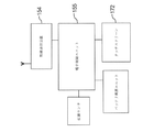
図28〜図31は、遠隔制御ユニット150およびその動作を示す。一実施形態では、遠隔制御ユニット150は、タッチスクリーン172付き携帯型タブレットコンピュータ150である。タブレットコンピュータ150は、無線通信装置154、バッテリ電源ユニット、位置センサ(GPS)、およびタッチスクリーン172に結合された電子制御ユニット155を備える。 28 to 31 show the remote control unit 150 and its operation. In one embodiment, the remote control unit 150 is a portable tablet computer 150 with a touch screen 172. The tablet computer 150 includes a wireless communication device 154, a battery power supply unit, a position sensor (GPS), and an electronic control unit 155 coupled to a touch screen 172.

一実施形態では、遠隔制御ユニット150は、タグボート2が被支援船舶1の位置を識別することができるように、すなわち、タグボート2が被支援船舶1の近くの動員位置に到達しやすくなるように、遠隔制御ユニット150の(GPS)位置をタグボート2に送信するように構成される。 In one embodiment, the remote control unit 150 allows the tugboat 2 to identify the position of the supported vessel 1, that is, facilitates the tugboat 2 to reach a mobilization position near the supported vessel 1. , The (GPS) position of the remote control unit 150 is configured to be transmitted to the tugboat 2.

電子制御ユニット155は、表示画面上に船体の輪郭の形で被支援船舶1を表示すると共に、図28に示されているように、航跡図に被支援船舶1に接続されたタグボート2(TUG1、TUG2、・・・TUGn)の位置を表示するように構成される。被支援船舶1の所望の係留位置は、例として、係留位置が破線で示された船舶1の輪郭で示されている。パイロットは、タッチスクリーンを使用して被支援船舶1を拡大表示して、曳航索10が取り付けられる被支援船舶1上の位置を選択することができる。可能な取付位置は、図30のスクリーンショットに示されているように、被支援船舶1の輪郭内の破線円で示されている。パイロットは、タッチスクリーン172を使用して接続位置を変更することができ、パイロットは、関与しているタグボート2に指示を送信するためにタッチスクリーン172上のタグボート2の1つを選択することができる。パイロットは、関与しているタグボート2をタッチスクリーン上の別の位置に移動させることによって、タグボート2の所望の位置を変更することができる。 The electronic control unit 155 displays the supported vessel 1 in the form of the outline of the hull on the display screen, and as shown in FIG. 28, the tugboat 2 (TUG1) connected to the supported vessel 1 in the track map. , TUG2, ... TUGn). The desired mooring position of the supported vessel 1 is shown, for example, by the outline of the vessel 1 whose mooring position is indicated by a broken line. The pilot can use the touch screen to magnify the supported vessel 1 and select the position on the supported vessel 1 to which the towline 10 is attached. Possible mounting positions are indicated by dashed circles within the contour of the supported vessel 1, as shown in the screenshot of FIG. The pilot can use the touch screen 172 to change the connection position, and the pilot can select one of the tugboats 2 on the touchscreen 172 to send instructions to the tugboats 2 involved. can. The pilot can change the desired position of the tugboat 2 by moving the tugboat 2 involved to another position on the touch screen.

図31は、特定のタグボート2が選択されたときのタッチスクリーン172上の情報を示したスクリーンショットである。実線ベクトルは、関与しているタグボート2(この特許のケースではTUG1)によって加えられた現在の推力の大きさおよび方向を示している。示されている現在の推力の大きさおよび方向は、(もしあれば)直近で出された推力指示に従う、またはタグボート2上のセンサによって検出された曳航索10上の力の大きさおよび/または方向に従うものであり得る。 FIG. 31 is a screenshot showing information on the touch screen 172 when a particular tugboat 2 is selected. The solid vector indicates the magnitude and direction of the current thrust applied by the tugboat 2 involved (TUG1 in the case of this patent). The current thrust magnitudes and directions shown follow the most recent thrust instructions (if any), or the magnitude and / or force on the towline 10 detected by the sensors on the tugboat 2. It can follow the direction.

パイロットは、タッチスクリーン172を使用することによって、図31に破線ベクトルで示されるように、新しい推力の大きさおよび方向を示すことができる。パイロットは、タッチスクリーン172上に「変更を実行する」と表示された仮想ボタンを押すことによって、関与しているタグボート2に対する新しい推力指示の変更および送信を実行することができる。 By using the touch screen 172, the pilot can indicate the magnitude and direction of the new thrust, as shown by the dashed line vector in FIG. The pilot can change and send new thrust instructions to the tugboat 2 involved by pressing the virtual button labeled "Perform changes" on the touch screen 172.

タグボート2上の通信装置54が遠隔制御ユニット150から新しい推力コマンドを受信したときに、電子制御ユニット50は、推力コマンドに応答してエンジン/モータおよびアジマススラスタ28を制御して、被支援船舶1に対してある大きさおよび方向の推力を加える。 When the communication device 54 on the tugboat 2 receives a new thrust command from the remote control unit 150, the electronic control unit 50 controls the engine / motor and the azimuth thruster 28 in response to the thrust command to control the supported vessel 1. A thrust of a certain magnitude and direction is applied to.

遠隔制御ユニット150はさらに、タグボート2に対して被支援船舶を追尾するコマンドを出すためにパイロットによって使用され得る。無線通信装置54によって被支援船舶を追尾する指示を受信することに応答して、電子制御ユニット50は、指示に基づいてエンジンおよびアジマススラスタ(ノズルドライブ)28を操作する。したがって、電子制御ユニット50は、タグボート2に一定の距離を置いて被支援船舶1を追尾させる、さらに好ましくは、電子制御ユニット50は、タグボート2に一定の距離を置いて、かつ被支援船舶1に対する一定の相対位置で、被支援船舶1を追尾させる。 The remote control unit 150 can also be used by the pilot to issue a command to the tugboat 2 to track the supported vessel. In response to receiving an instruction to track the supported vessel by the wireless communication device 54, the electronic control unit 50 operates the engine and the azimuth thruster (nozzle drive) 28 based on the instruction. Therefore, the electronic control unit 50 keeps the tugboat 2 at a certain distance to track the supported vessel 1, and more preferably, the electronic control unit 50 keeps the tugboat 2 at a certain distance and the supported vessel 1 is tracked. The supported vessel 1 is tracked at a certain relative position with respect to.

遠隔制御ユニット150には、一実施形態では、タグボート2上のマイクロホン(装置)によって拾われた音を再生する、またはパイロットがタグボート2から受信する必要のある他の情報を再生するためのラウドスピーカが設けられる。 The remote control unit 150, in one embodiment, is a loudspeaker for reproducing the sound picked up by the microphone (device) on the tugboat 2 or for reproducing other information that the pilot needs to receive from the tugboat 2. Is provided.

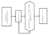
一実施形態では、タグボート2には、スプレッダバー111(図32)を使用してタグボート22を陸110上のボラード112に固定する自動係留システムが設けられる。クレーン22は、スプレッダバー110を操作する、すなわち、タグボート上またはタグボートの位置からボラード112の後ろ(タグボート2から見て後ろ)の位置までスプレッダバーを移動させるのに使用される。係留索は、スプレッダバー111の各々の端部に取り付けられ、係留索は、好ましくは、1つまたは複数の小型動力ウィンチ(図示せず)を含む自動張力付与システムを介して、タグボート2に固定される。図18は、タグボート2を自動的に係留および解放する方法の一実施形態を示す。タグボート2が接岸状態にあるとき、タグボート2は、通信装置54を介して任務命令を受信し、電子制御ユニット50は、任務目的を処理して航路を計画する。次に、電子制御ユニット50は、何らかのシステムエラーまたは近くの障害物が存在するかどうかを確認して、何らかのシステムエラーまたは近くの障害物が存在する場合、電子制御ユニット50は、接岸状態で留まることを決定し、通信装置54を介して制御センター200にその問題を報告して、プロセスが終了する。何らかのシステムエラーまたは近くの障害物が存在しない場合、電子制御ユニット50は、自動係留システムを作動させて、陸からタグボートを解放する。次に、任務が実行され、電子制御ユニットは、任務が完了したかどうかを確認する。任務が完了した場合、電子制御ユニット50は、帰りの航路を計画して実行することによって係船場所まで戻るようにタグボート2を制御する。係船場所の近くでは、電子制御ユニットは、状況を認識するために利用可能なセンサ信号を使用して、タグボートを接岸させるように慎重に操縦する。その際に、電子制御ユニット50は、自動係留システムを作動させてタグボート2を陸に繋ぎ、プロセスはブロック「接岸」に戻る。 In one embodiment, the tugboat 2 is provided with an automatic mooring system that secures the tugboat 22 to the bollard 112 on land 110 using a spreader bar 111 (FIG. 32). The crane 22 is used to operate the spreader bar 110, i.e., to move the spreader bar from the position on the tugboat or from the position of the tugboat to the position behind the bollard 112 (behind the tugboat 2). The mooring line is attached to each end of the spreader bar 111, and the mooring line is preferably secured to the tugboat 2 via an automatic tensioning system including one or more small power winches (not shown). Will be done. FIG. 18 shows an embodiment of a method of automatically mooring and releasing a tugboat 2. When the tugboat 2 is in the berthing state, the tugboat 2 receives a mission command via the communication device 54, and the electronic control unit 50 processes the mission purpose to plan the route. Next, the electronic control unit 50 checks whether there is any system error or nearby obstacle, and if there is any system error or nearby obstacle, the electronic control unit 50 stays in the berthing state. It is determined that the problem is reported to the control center 200 via the communication device 54, and the process ends. In the absence of any system error or nearby obstacles, the electronic control unit 50 activates an automated mooring system to release the tugboat from land. The mission is then performed and the electronic control unit checks to see if the mission is complete. When the mission is completed, the electronic control unit 50 controls the tugboat 2 to return to the mooring location by planning and executing a return route. Near the mooring site, the electronic control unit carefully steers the tugboat to berth using sensor signals available to recognize the situation. At that time, the electronic control unit 50 activates the automatic mooring system to connect the tugboat 2 to the land, and the process returns to the block "berthing".

図19は、タグボート2が待機位置にある状態で開始され、その後、通信装置54を介して命令を受信するタグボート2の操作方法を示すフローチャートである。電子制御ユニット50は、任務目的を処理し、航路を計画して実行する。衝突防止システムによって障害物が検出された場合、以下でさらに詳細に説明するように、電子制御ユニット50は、必要に応じて回避行動を取って新しい航路を計画する。タグボート2が被支援船舶1に近くに到着すると、タグボート2は被支援船舶1上のパイロットからの新しい指示/コマンドを待つ。 FIG. 19 is a flowchart showing an operation method of the tugboat 2 which is started in a state where the tugboat 2 is in the standby position and then receives a command via the communication device 54. The electronic control unit 50 processes mission objectives, plans and executes routes. If an obstacle is detected by the anti-collision system, the electronic control unit 50 takes evasive action as necessary to plan a new route, as described in more detail below. When the tugboat 2 arrives near the supported vessel 1, the tugboat 2 waits for a new instruction / command from the pilot on the supported vessel 1.

図20は、被支援船舶1の近くにいる状態で、曳航索10に張力をかけて被支援船舶1を追尾する指示を受信するタグボート2の操作方法を示すフローチャートである。次のステップで、電子制御ユニット50は、利用可能なセンサ情報を使用して、曳航索10上の張力が規定範囲内にあることを確認する。張力が規定範囲内である場合、電子制御ユニットは、タグボート2が、一定の距離を置いて、曳航索10に必要な張力がかけられた状態で被支援船舶1を追尾するように制御を続ける。張力が最小閾値未満である場合、電子制御ユニット50は、曳航索10上の張力を増加させるためにタグボート2の操作を制御する。曳航索10上の張力が最高閾値を超える場合、電子制御ユニット50は、曳航索10上の張力を減少させるためにタグボート2の操作を制御する。曳航索10の張力変更は、例えば、エンジン/モータがアジマススラスタ28に送る動力を変化させることによって達成される。 FIG. 20 is a flowchart showing an operation method of the tugboat 2 for receiving an instruction to apply tension to the towline 10 and track the supported vessel 1 while being near the supported vessel 1. In the next step, the electronic control unit 50 uses the available sensor information to confirm that the tension on the towline 10 is within the specified range. When the tension is within the specified range, the electronic control unit continues to control the tugboat 2 to track the supported vessel 1 at a certain distance with the necessary tension applied to the towline 10. .. If the tension is less than the minimum threshold, the electronic control unit 50 controls the operation of the tugboat 2 to increase the tension on the towline 10. When the tension on the towline 10 exceeds the maximum threshold, the electronic control unit 50 controls the operation of the tugboat 2 to reduce the tension on the towline 10. The tension change of the towline 10 is achieved, for example, by changing the power sent by the engine / motor to the azimuth thruster 28.

図21は、被支援船舶1の近くの待機位置にいる状態で、曳航索10を被支援船舶上の特定の位置に渡すようにとの指示を受信するタグボート2の操作方法を示すフローチャートである。この点に関して、電子制御ユニット50は、例えば、曳航索10を受け取る準備ができている被支援船舶1の甲板上の乗組員を識別するために、ビーコンXを使用して、またはカメラおよび画像処理ソフトウェアを使用して、被支援船舶1上の受渡地点を識別する。次に、電子制御ユニット50は、タグボート2を所定位置へと、すなわち、識別された受渡地点の近くまで航行させるようにタグボート2を制御する。次に、電子制御ユニット50は、クレーンアームを伸長するための基準が満たされていることを確認する。クレーンアームを伸長するための基準が満たされていない場合、電子制御ユニット50は、タグボートの位置を調整する、またはクレーン22の安定性(動き補正)を調整する。クレーンアームを伸長するための基準が満たされている場合、電子制御ユニット50は、タグボートの位置を維持し、クレーン操作を開始および/または継続して、安全基準が範囲外であるかどうかを確認する。安全基準が範囲外である場合、クレーン操作は終了する。次に、タグボート2ならびに/もしくはクレーン22の位置が調整され、クレーン2の安定性が調整される、およびまたは安全基準を満たすために他の基準が調整される。安全基準が範囲内である場合、曳航索10が受け取られたという肯定応答を通信装置54が被支援船舶1から受信するまで、クレーン操作は継続される。この肯定応答が受信されなかった場合、クレーン操作は継続される。肯定応答が受信されると、クレーン操作は終了し、クレーンは収縮されて、図5に示されている休止位置で格納される。 FIG. 21 is a flowchart showing an operation method of the tugboat 2 for receiving an instruction to pass the towline 10 to a specific position on the supported vessel while in a standby position near the supported vessel 1. .. In this regard, the electronic control unit 50 may use the Beacon X or perform camera and image processing, for example, to identify the crew on the deck of the supported vessel 1 ready to receive the towline 10. The software is used to identify the delivery point on the supported vessel 1. Next, the electronic control unit 50 controls the tugboat 2 so as to navigate the tugboat 2 to a predetermined position, that is, close to the identified delivery point. Next, the electronic control unit 50 confirms that the criteria for extending the crane arm are satisfied. If the criteria for extending the crane arm are not met, the electronic control unit 50 adjusts the position of the tugboat or adjusts the stability (movement correction) of the crane 22. If the criteria for extending the crane arm are met, the electronic control unit 50 will maintain the position of the tugboat and start and / or continue the crane operation to check if the safety standards are out of range. do. If safety standards are out of range, the crane operation is terminated. Next, the position of the tugboat 2 and / or the crane 22 is adjusted, the stability of the crane 2 is adjusted, and / or other standards are adjusted to meet safety standards. If the safety standards are within range, the crane operation will continue until the communication device 54 receives an acknowledgment from the supported vessel 1 that the towline 10 has been received. If this acknowledgment is not received, the crane operation will continue. Upon receipt of the acknowledgment, the crane operation is terminated and the crane is retracted and stowed in the dormant position shown in FIG.

図22に示されているように、電子制御ユニット50は、曳航索10が渡されたとの肯定応答を受信した後、曳航索10を繰り出しながらタグボート2と被支援船舶1との間の距離を調整する。このプロセスは、必要な距離に達するまで継続される。必要な距離に達すると、プロセスは、被支援船舶1からの推力コマンドを待つプロセスに移る。 As shown in FIG. 22, after receiving the acknowledgment that the towline 10 has been passed, the electronic control unit 50 determines the distance between the tugboat 2 and the supported vessel 1 while paying out the towline 10. adjust. This process continues until the required distance is reached. When the required distance is reached, the process shifts to the process of waiting for a thrust command from the supported vessel 1.

図24は、推力コマンドが受信されるときのプロセスを示す。タグボートは、曳航索10が被支援船舶1に接続された状態で待機位置にある。電子制御ユニットは、電子制御ユニット150から通信装置54を介してパイロットによって出された推力コマンドを受信する。推力コマンドは、加える必要のある推力の大きさおよび方向を示す推力ベクトルを含む。一実施形態では、推力コマンドはさらに、推力位置、すなわち、推力コマンドを実行すべき被支援船舶1に対する位置を含み得、推力コマンドはさらに、推力角度を含み得る。あるいは、電子制御ユニットは、最適な推力角度を決定するように構成され得る。電子制御ユニット50は、推力コマンドを受信したときに、タグボート2を推力位置まで移動させるように制御する。次に、電子制御ユニット50は、タグボート2が推力位置および角度に達したことを確認する。タグボート2が推力位置に達していない場合、電子制御ユニットは、タグボート2の位置を調整して、最適な推力角度まで船体を回転させる。タグボート2が推力位置および角度に達したときに、電子制御ユニット50は、曳航索10が必要な張力に達するまで、曳航索10に加わる推力を徐々に増大させる。その際に、電子制御ユニット50は、曳航索10上の必要な張力を維持して、被支援船舶1から(遠隔制御ユニット150から)次のコマンドを待つと同時に、曳航索10上の張力を維持するために推力調整が必要であるかどうかを判断する。新しい推力コマンドが遠隔制御ユニット150から受信された場合、電子制御ユニットは、タグボート2の位置を調整して、最適な推力角度まで船体を回転させる。次に、プロセスは、ボックス「推力位置に達したか?」まで戻り、プロセスは繰り返される。推力コマンドが受信されない場合、電子制御ユニットは、推力任務が完了したかどうかを確認する。推力任務が完了していない場合、プロセスはボックス「被支援船舶からコマンドを待つ。推力調整が必要か?」に戻る。推力任務が完了した場合、プロセスはボックス「待機位置に移動する」に戻る。 FIG. 24 shows the process when a thrust command is received. The tugboat is in a standby position with the towline 10 connected to the supported vessel 1. The electronic control unit receives a thrust command issued by the pilot from the electronic control unit 150 via the communication device 54. The thrust command contains a thrust vector indicating the magnitude and direction of the thrust that needs to be applied. In one embodiment, the thrust command may further include a thrust position, i.e., a position with respect to the supported vessel 1 on which the thrust command should be executed, and the thrust command may further include a thrust angle. Alternatively, the electronic control unit may be configured to determine the optimum thrust angle. The electronic control unit 50 controls the tugboat 2 to move to the thrust position when the thrust command is received. Next, the electronic control unit 50 confirms that the tugboat 2 has reached the thrust position and angle. If the tugboat 2 has not reached the thrust position, the electronic control unit adjusts the position of the tugboat 2 to rotate the hull to the optimum thrust angle. When the tugboat 2 reaches the thrust position and angle, the electronic control unit 50 gradually increases the thrust applied to the towline 10 until the towline 10 reaches the required tension. At that time, the electronic control unit 50 maintains the necessary tension on the towline 10, waits for the next command from the supported vessel 1 (from the remote control unit 150), and at the same time, applies the tension on the towline 10. Determine if thrust adjustment is needed to maintain. When a new thrust command is received from the remote control unit 150, the electronic control unit adjusts the position of the tugboat 2 to rotate the hull to the optimum thrust angle. The process then returns to the box "Have you reached the thrust position?" And the process repeats. If no thrust command is received, the electronic control unit checks to see if the thrust mission is complete. If the thrust mission is not completed, the process returns to the box "Wait for command from supported vessel. Need thrust adjustment?". When the thrust mission is completed, the process returns to the box "Move to Standby".

図24のプロセスは、被支援船舶の船体3上のストロングポイント9をタグボート2の船首27と係合させることで推力がタグボート2によって加えられることを除いて、実際には図25のプロセスと同じである。説明したように、電子制御ユニット50は、船体3上の印を識別するためのカメラおよび画像認識ソフトウェアを使用してストロングポイント9を識別する。図24のプロセスでは、必要な推力が加えられたこと確認するために曳航索10上の張力を使用することができない。その代わりに、電子制御ユニットは、タグボート2のルックアップテーブルまたは数学モデルを使用して、被支援船舶1の船体3に加えられる推力の必要量および方向を達成するように推進器を制御する。 The process of FIG. 24 is actually the same as the process of FIG. 25, except that thrust is applied by the tugboat 2 by engaging the strong point 9 on the hull 3 of the supported vessel with the bow 27 of the tugboat 2. Is. As described, the electronic control unit 50 identifies the strong point 9 using a camera and image recognition software for identifying marks on the hull 3. In the process of FIG. 24, the tension on the towline 10 cannot be used to confirm that the required thrust has been applied. Instead, the electronic control unit uses the tugboat 2 look-up table or mathematical model to control the propulsion unit to achieve the required amount and direction of thrust applied to the hull 3 of the supported vessel 1.

図25は、推力任務が完了したときに曳航索10を解放するプロセスを示す。電子制御ユニット50は、曳航索10が被支援船舶1から解放されたとの肯定応答の受信を待つ。この際に、制御ユニット50は、曳航索10を巻き上げるように動力ウィンチ21を作動させる。電子制御ユニット50は、巻き上げの間に、上述したように、曳航索50が完全に巻き上げられたかどうか、および曳航索10の自由端が格納位置にあることを確認する。曳航索10が完全に巻き上げられていない場合、巻き上げプロセスは継続される。曳航索10が完全に巻き上げられると、電子制御ユニット50は、遠隔制御ユニット150を介して被支援船舶1から、または制御センター200から次のコマンドを待つ。 FIG. 25 shows the process of releasing the towline 10 when the thrust mission is completed. The electronic control unit 50 waits for the reception of an acknowledgment that the towline 10 has been released from the supported vessel 1. At this time, the control unit 50 operates the power winch 21 so as to wind up the towing line 10. During winding, the electronic control unit 50 confirms whether the towline 50 has been completely wound up and that the free end of the towline 10 is in the retracted position, as described above. If the towline 10 is not completely wound up, the winding process continues. When the towline 10 is completely wound up, the electronic control unit 50 waits for the next command from the supported vessel 1 or from the control center 200 via the remote control unit 150.

図32は、陸110に係留されたタグボート2(クレーン22またはロボットアームが設けられた任意の他のタイプのボートであり得る)を示す。スプレッダバー111に接続された係留索は、ボート2を陸110に固定するのに使用される。クレーン22は、この実施形態では、ボート2が係留されたときに陸110への接続を確立するように構成される。陸110への接続は、電気的なデータ接続および/または電力接続であり得る。電子制御ユニット50は、クレーン22を使用して、陸への電気的接続を確立するように構成される。電子制御ユニット50は、ボート2が係留されたときに、このプロセスを自律的に実行するようにプログラムされ得、電子制御ユニット50はさらに、ボートが離岸しつつあるときに電気的接続を切断するように構成される。電子制御ユニット50は、接続を確立するためにコネクタを陸上の接続点と接続するように構成される。一実施形態では、コネクタは、誘導接続を確立するためにコイル95で形成される。陸110上の接続相手は、陸(岸壁など)上の対応電極99のコイルである。コイル95には、電極99に適合するサイズおよび形状の開口部が設けられる。コイル95には、把持要素97が取り付けられる。把持要素97は、ブッシング15と同様または同一の形状およびサイズを有する。したがって、把持要素97は把持具42と合致し、そのことにより、コイル95を把持具42で操作することができる。コイル95には、ボート2上に設けられたケーブルリール98まで延在する電力ケーブル96が取り付けられ、ケーブルリール98は、ボート2の電気系統に接続される。コイル95は、使用されていないときは、図31の破線で示されているように、クレーン22によってボート2の甲板上の単純電極91の上に配置される。 FIG. 32 shows a tugboat 2 moored on land 110, which may be a crane 22 or any other type of boat provided with a robotic arm. The mooring line connected to the spreader bar 111 is used to secure the boat 2 to the land 110. In this embodiment, the crane 22 is configured to establish a connection to the land 110 when the boat 2 is moored. The connection to land 110 can be an electrical data connection and / or a power connection. The electronic control unit 50 is configured to use a crane 22 to establish an electrical connection to land. The electronic control unit 50 may be programmed to perform this process autonomously when the boat 2 is moored, and the electronic control unit 50 also disconnects electrical connections when the boat is leaving the shore. It is configured to do. The electronic control unit 50 is configured to connect the connector to a land connection point to establish a connection. In one embodiment, the connector is formed of a coil 95 to establish an inductive connection. The connection partner on the land 110 is the coil of the corresponding electrode 99 on the land (such as a quay). The coil 95 is provided with an opening of a size and shape that fits the electrode 99. A gripping element 97 is attached to the coil 95. The grip element 97 has the same or the same shape and size as the bushing 15. Therefore, the gripping element 97 matches the gripping tool 42, whereby the coil 95 can be operated by the gripping tool 42. A power cable 96 extending to the cable reel 98 provided on the boat 2 is attached to the coil 95, and the cable reel 98 is connected to the electric system of the boat 2. When not in use, the coil 95 is placed by the crane 22 on a simple electrode 91 on the deck of the boat 2, as shown by the dashed line in FIG.

電子制御ユニット50は、把持具42および把持要素97を使用してコイル95をボート2の甲板から持ち上げて、陸上の電極99に向けて電極99の上までコイル95を移動させるように構成される。したがって、誘導電気的接続は、電力および/またはデータを送信するのに使用され得る陸で確立される。 The electronic control unit 50 is configured to lift the coil 95 from the deck of the boat 2 using the grip 42 and the grip element 97 and move the coil 95 toward the land electrode 99 over the electrode 99. .. Therefore, inductive electrical connections are established on land that can be used to transmit power and / or data.

電子制御ユニット50は、ボートが係留された状態で電気的接続を維持するように構成されるので、例えば、ボート2に搭載されているバッテリを充電することができ、ボート2に搭載されている電気機器に電力を供給することができる。電子制御ユニット50は、コネクタ95がコイル99の形態の接続点に接続された状態で陸に対するボート2の移動を調節するために、クレーン22アームを自由に移動させることができる。 Since the electronic control unit 50 is configured to maintain an electrical connection while the boat is moored, for example, the battery mounted on the boat 2 can be charged and mounted on the boat 2. It can supply electric power to electrical equipment. The electronic control unit 50 can freely move the crane 22 arm in order to adjust the movement of the boat 2 with respect to the land while the connector 95 is connected to the connection point in the form of the coil 99.

電子制御ユニット50は、ボート2が離岸しなければならない、例えば、作業を開始しなければならないときに、電気的接続を切断するように構成される。電子制御ユニット50は、把持具42を使用して把持要素97を掴み、岸壁のコイル付き電極99からコイル95を持ち上げて、甲板上の電極91に向けて電極91の上までコイル95を移動させるように構成される。 The electronic control unit 50 is configured to disconnect the electrical connection when the boat 2 has to leave the shore, for example, to start work. The electronic control unit 50 grips the gripping element 97 using the gripping tool 42, lifts the coil 95 from the coiled electrode 99 on the quay, and moves the coil 95 toward the electrode 91 on the deck and above the electrode 91. It is configured as follows.

一実施形態では、ケーブルリール98は、弾性手段または他の適切な手段を使用して、電力ケーブル96上の所定量の張力を維持しながら電力ケーブル96の巻き上げおよび繰り出しを自動的に行う。 In one embodiment, the cable reel 98 uses elastic means or other suitable means to automatically wind and unwind the power cable 96 while maintaining a predetermined amount of tension on the power cable 96.

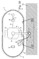
一実施形態では、タグボート2は、曳航索10上の過負荷による転覆または沈没を自動的に防止するように構成される。この点に関して、タグボート2には、曳航索10がタグボート2に及ぼす引張力の大きさおよび方向を検知するように構成されたセンサ装置が設けられる。このセンサ装置は、動力ウィンチ21に加わるトルクを決定する動力ウィンチ21上のセンサと、特にタグボート2に曳航索が及ぼす力の方向を決定するのに役立つビット11、12における歪みゲージなどとの組み合わせであり得る。さらに、タグボート2には、タグボートの向きを検知するように構成されたセンサ装置が設けられる。この目的のために、モーションセンサ(エモーション参照ユニット)が使用され得る。センサ装置は、電子制御ユニット50に検知情報または検知信号を送信するように構成される。電子制御ユニット50は、センサ装置から検知情報または検知信号を受信するように構成される。電子制御ユニット50は、有線または無線構成のセンサ装置に接続され得る。電子制御ユニット50は、上記センサの信号を受信し、電子制御ユニット50に、推進器によって生成された推力の大きさおよび方向が伝えられる。いくつかの実施形態では、電子制御ユニット50は、推進器によって生成された推力の大きさおよび方向を検知するセンサ装置に結合される。代替的に、または追加的に、他の実施形態では、推力の大きさおよび方向を検出するセンサは存在せず、その代わりに、推進器の制御ユニットが電子制御ユニット50と直接通信する。推進器の制御ユニットは、推進器の推力の大きさおよび方向に関する情報を電子制御ユニット50に送信する。いくつかの実施形態では、電子制御ユニット50は、推力に関する情報を受信するように構成される。このようにして、電子制御ユニット50には、複数の方法のうちの1つまたは複数によって推力の大きさおよび方向に関する情報が伝えられる。電子制御ユニット50は、検知された推力の大きさならび方向、検知された引張力の大きさならびに方向、および検知されたタグボートの向きに基づいて、タグボート2が安全閾値を超えているかどうかを判断する。安全閾値は、タグボート2の水平線に対する最大傾きを含み得る。いくつかの実施形態では、電子制御ユニット50は、本願の実施形態に関して述べた動作閾値に関する情報を含む電子メモリまたは記憶装置を備える。電子メモリはさらに、所定の安全閾値情報に関する情報を含み得る。例えば、電子制御ユニット50は、検知された情報に基づいた引張力の決定された大きさならびに方向およびタグボートの決定された向きを、記憶されている所定のタグボートの最大傾きおよび/または引張力の所定の大きさならびに方向と比較する。電子制御ユニット50は、1つまたは複数の状況に対して変化する複数の所定の安全閾値およびまたは動作閾値を含むルックアップテーブルを参照し得る。電子制御ユニット50には、例えば、推進器から、例えば、推進器によって生成された推力の大きさおよび方向を表す信号によって、推進器によって生成された推力の大きさおよび方向が伝えられる。 In one embodiment, the tugboat 2 is configured to automatically prevent capsizing or sinking due to overload on the towline 10. In this regard, the tugboat 2 is provided with a sensor device configured to detect the magnitude and direction of the tensile force exerted by the tugboat 10 on the tugboat 2. This sensor device is a combination of a sensor on the power winch 21 that determines the torque applied to the power winch 21, and a strain gauge on the bits 11 and 12 that are particularly useful in determining the direction of the force exerted by the tugboat 2 on the tugboat 2. Can be. Further, the tugboat 2 is provided with a sensor device configured to detect the direction of the tugboat. A motion sensor (emotion reference unit) may be used for this purpose. The sensor device is configured to transmit detection information or detection signal to the electronic control unit 50. The electronic control unit 50 is configured to receive detection information or detection signal from the sensor device. The electronic control unit 50 may be connected to a sensor device in a wired or wireless configuration. The electronic control unit 50 receives the signal of the sensor, and the magnitude and direction of the thrust generated by the propulsion unit are transmitted to the electronic control unit 50. In some embodiments, the electronic control unit 50 is coupled to a sensor device that detects the magnitude and direction of thrust generated by the propeller. Alternatively or additionally, in other embodiments, there is no sensor to detect the magnitude and direction of thrust, instead the control unit of the propulsion unit communicates directly with the electronic control unit 50. The control unit of the propulsion unit transmits information regarding the magnitude and direction of the thrust of the propulsion unit to the electronic control unit 50. In some embodiments, the electronic control unit 50 is configured to receive information about thrust. In this way, the electronic control unit 50 is informed about the magnitude and direction of thrust by one or more of the plurality of methods. The electronic control unit 50 determines whether or not the tag boat 2 exceeds the safety threshold based on the detected magnitude and direction of the thrust, the detected magnitude and direction of the tensile force, and the detected orientation of the tag boat. do. The safety threshold may include the maximum slope of the tugboat 2 with respect to the horizon. In some embodiments, the electronic control unit 50 comprises an electronic memory or storage device that includes information about the operating thresholds described for embodiments of the present application. The electronic memory may further contain information regarding predetermined safety threshold information. For example, the electronic control unit 50 may store a determined magnitude and direction of tugboat based on the detected information and a determined orientation of the tugboat for the maximum tilt and / or tensile force of a given tugboat stored. Compare with a given size and direction. The electronic control unit 50 may refer to a look-up table containing a plurality of predetermined safety thresholds and / or operation thresholds that change for one or more situations. To the electronic control unit 50, for example, the magnitude and direction of the thrust generated by the propulsion device are transmitted from the propulsion device, for example, by a signal indicating the magnitude and direction of the thrust generated by the propulsion device.

いくつかの実施形態では、電子制御ユニット50は、安全閾値を超えたかどうかを判断する。一実施形態では、安全閾値を超えていると電子制御ユニット50が判断した場合に、電子制御ユニット50は、推力の大きさを低減し、および/または推力の方向を変更する。好ましくは、電子制御ユニットは、通信装置54を介して、この推力の大きさの低減およびまたは推力の方向の変更を制御センター200または遠隔制御センター150に無線で伝える。 In some embodiments, the electronic control unit 50 determines if the safety threshold has been exceeded. In one embodiment, when the electronic control unit 50 determines that the safety threshold has been exceeded, the electronic control unit 50 reduces the magnitude of the thrust and / or changes the direction of the thrust. Preferably, the electronic control unit wirelessly transmits the reduction in the magnitude of the thrust and / or the change in the direction of the thrust to the control center 200 or the remote control center 150 via the communication device 54.

一実施形態では、タグボート2には、電子制御ユニット50からのコマンドに応答して、タグボート2を曳航索10から切り離す装置が設けられ、好ましくは、該装置は、曳航索10を切断する器具を備える。切断することによってタグボート2を曳航索10から切り離す装置は、好ましくは、曳航索10を切断するために、ナイフもしくは斧など、または一般にポリマー系の曳航索10に熱を加える要素を含む。 In one embodiment, the tugboat 2 is provided with a device for disconnecting the tugboat 2 from the towline 10 in response to a command from the electronic control unit 50, preferably such a device as an instrument for cutting the towline 10. Be prepared. A device that separates the tugboat 2 from the towline 10 by cutting preferably comprises a knife or ax or the like, or generally a polymer-based towline 10, to heat the towline 10 in order to cut the towline 10.

電子制御ユニット50は、好ましくは、タグボート2が第1の安全閾値より高い第2の安全閾値を超えたと電子制御ユニット50が判断したときに、曳航索10を切断するように構成される。一実施形態では、第1の安全閾値ならびに第2の安全閾値はタグボートが転覆するリスクであり、および/または第1の安全閾値ならびに第2の安全閾値はタグボートが沈没するリスクである。 The electronic control unit 50 is preferably configured to cut the towline 10 when the electronic control unit 50 determines that the tugboat 2 has exceeded a second safety threshold higher than the first safety threshold. In one embodiment, the first and second safety thresholds are the risk of the tagboat overturning, and / or the first and second safety thresholds are the risk of the tagboat sinking.

一実施形態では、電子制御ユニット50は、タグボート2の挙動をシミュレートするコンピュータモデルに基づいて、タグボート2が転覆または沈没するリスクを判断するように構成される。この点に関して、電子制御ユニット50には、推力、曳航索の力ならびに方向、および任意で波に反応したタグボート2の挙動をシミュレートするタグボート2の数学モデルが設けられ得る。 In one embodiment, the electronic control unit 50 is configured to determine the risk of capsizing or sinking of the tugboat 2 based on a computer model that simulates the behavior of the tugboat 2. In this regard, the electronic control unit 50 may be provided with a mathematical model of the tagboat 2 that simulates the thrust, the force and direction of the towline, and optionally the behavior of the tagboat 2 in response to waves.

したがって、一実施形態では、電子制御ユニット50は、タグボート2の推進器によって生成された推力の大きさおよび方向を決定し、曳航索10によってタグボート1に加えられた引張力の大きさおよび方向を決定し、タグボート2の向きを決定し、推力の大きさおよび方向と、引張力の大きさおよび方向と、タグボート2の向きとの組み合わせが安全閾値を超えているかどうかを判断する。電子制御ユニット50はさらに、タグボート2が安全閾値を超えるのを防止するために、推力の大きさおよび/または方向を調整するように構成され得る。電子制御ユニットはさらに、安全閾値を超えたときに曳航索10を切断するように構成され得る。 Therefore, in one embodiment, the electronic control unit 50 determines the magnitude and direction of the thrust generated by the tugboat 2 propulsion and the magnitude and direction of the tensile force applied to the tugboat 1 by the tugboat 10. Determine, determine the orientation of the tugboat 2, and determine if the combination of the magnitude and direction of the thrust, the magnitude and direction of the tensile force, and the orientation of the tugboat 2 exceeds the safety threshold. The electronic control unit 50 may also be configured to adjust the magnitude and / or direction of thrust to prevent the tugboat 2 from exceeding the safety threshold. The electronic control unit may also be configured to disconnect the towline 10 when the safety threshold is exceeded.

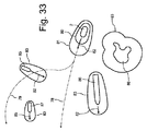
一実施形態では、ボートまたは船舶(任意のタイプのボート、船または船舶であり得、タグボート2である必要はない)には、例えば、他のボートまたは船舶のような障害物との衝突を回避するように乗組員を支援し得る衝突防止システムが設けられる。一実施形態では、ボートまたは船舶は、第1のリスクレベルを超えた場合に乗組員に警告を発するように構成され、一実施形態では、ボートまたは船舶はさらに、第1のリスクレベルより高い第2のリスクレベルを超えたときに乗組員が回避行動を取った場合に回避行動を取るように構成される。さらに、衝突防止システムは、自律的動作するボートまたは船舶で使用され得、この場合、衝突防止システムは、第1のリスクレベルを超えたときに遠隔の受信者に無線で送信される警告を発し、第2のリスクレベルを超えたときにナビゲーションシステムが回避行動を取る。図33は、衝突防止システムの機能を示すために図上でシナリオを示す。 In one embodiment, the boat or ship (which can be any type of boat, ship or ship, not necessarily tugboat 2) avoids collision with obstacles such as other boats or ships. A collision prevention system will be provided that can assist the crew to do so. In one embodiment, the boat or ship is configured to warn the crew if the first risk level is exceeded, and in one embodiment the boat or ship is further higher than the first risk level. It is configured to take evasive action if the crew takes evasive action when the risk level of 2 is exceeded. In addition, anti-collision systems can be used on autonomously operating boats or vessels, in which case the anti-collision system issues a warning that is transmitted wirelessly to remote recipients when the first risk level is exceeded. , The navigation system takes evasive action when the second risk level is exceeded. FIG. 33 shows a scenario on the diagram to show the function of the anti-collision system.

図33に示されているように、衝突防止システム(電子制御ユニット50の一体部品であり得る)は、ボート2の周囲の第1の衝突ゾーン80を指定し、さらにボート2の周囲の第2の衝突ゾーン81を指定しており、第2の衝突ゾーン81は第1の衝突ゾーン80を取り囲む。第1の衝突ゾーン80の形状およびサイズと、第2の衝突ゾーン81の形状およびサイズは、ボートまたは船舶2の速度および船首方向に依存する。ボートまたは船舶2の速度および船首方向は、ベクトル82で示されている。 As shown in FIG. 33, the anti-collision system (which can be an integral part of the electronic control unit 50) designates a first collision zone 80 around the boat 2 and a second around the boat 2. The collision zone 81 is designated, and the second collision zone 81 surrounds the first collision zone 80. The shape and size of the first collision zone 80 and the shape and size of the second collision zone 81 depend on the speed and bow direction of the boat or vessel 2. The speed and bow direction of the boat or vessel 2 are indicated by the vector 82.

第1の衝突ゾーン80および第2の衝突ゾーン81は、ボートまたは船舶の船首方向に向かってより大きく、ボートまたは船舶2の速度が増すにつれて少なくとも船首方向に向かってより大きくなり、好ましくは、さらに船首方向の横断方向に向かってわずかに大きくなる。 The first collision zone 80 and the second collision zone 81 become larger toward the bow of the boat or ship, and at least toward the bow as the speed of the boat or ship 2 increases, preferably further. It increases slightly toward the crossing direction toward the bow.

図33に示されているように、衝突防止システムは、例えば、RADAR、LIDAR、およびカメラのようなボート2上のセンサを使用して複数障害物を検出している。この例では、検出された障害物は、プレジャーボート(ヨット)85、漁船87、貨物船86、および島88を含む。しかしながら、これは、可能性のある障害物の種類の単なる例に過ぎず、他の障害物の種類も検出可能であることは理解されよう。 As shown in FIG. 33, the anti-collision system uses sensors on the boat 2 such as RADAR, LIDAR, and cameras to detect multiple obstacles. In this example, the detected obstacles include pleasure boat (yacht) 85, fishing boat 87, cargo ship 86, and island 88. However, it should be understood that this is just an example of possible obstacle types, and other obstacle types are also detectable.

衝突防止システムは、カテゴリを各々の検出された障害物に割り当てるように構成される。カテゴリの例は、例えば、水上乗り物、固定構造物、浅海域、陸であり、カテゴリは、好ましくは、ボート、船舶を含む水上乗り物の複数のカテゴリを含み、前記ボートの複数のカテゴリは、さらに好ましくは、漁船、タグボート、スピードボート、ヨットおよび帆走ヨットを含み、前記船舶のカテゴリは、貨物船、海軍船艇、クルーズ船およびフェリーを含む。しかしながら、このリストは単なる例に過ぎず、このリストは網羅的リストでないことは理解されよう。 The anti-collision system is configured to assign categories to each detected obstacle. Examples of categories are, for example, surface vehicles, fixed structures, shallow waters, land, the categories preferably include multiple categories of surface vehicles including boats, ships, and the plurality of categories of said boats further. Preferably, the boat category includes fishing boats, tag boats, speed boats, yachts and sailing yachts, and the vessel category includes freight boats, naval boats, cruise boats and ferries. However, it should be understood that this list is just an example and this list is not an exhaustive list.

各々のカテゴリには、例えば、好ましくは(利用可能であれば)検出障害物のナビゲーション計画に対する、また(利用可能であれば)検出障害物の数学モデルを使用した、検出障害物の位置変更、針路変更および/または速度変更の可能性に関する情報が関連付けられている。各々のカテゴリには、好ましくは検出障害物の検出された速度および船首方向(検出されれば)に対して、第1の衝突ゾーンならびに第2の衝突ゾーンの形状およびサイズに関する情報が関連付けられている場合もある。 For each category, eg, repositioning of the detected obstacle, preferably for a navigation plan for the detected obstacle (if available) and using a mathematical model of the detected obstacle (if available). Information about the possibility of course changes and / or speed changes is associated. Each category is associated with information about the shape and size of the first and second collision zones, preferably with respect to the detected speed and bow direction (if detected) of the detected obstacle. In some cases.

一実施形態では、ナビゲーションシステムは、検出障害物の針路を追跡するように構成される。一実施形態では、ナビゲーションシステムは、好ましくは障害物が配置されているカテゴリに基づいて、検出障害物の針路および/または速度の変更の可能性を決定するように構成される。 In one embodiment, the navigation system is configured to track the course of the detected obstacle. In one embodiment, the navigation system is configured to determine the potential course and / or speed change of the detected obstacle, preferably based on the category in which the obstacle is located.

ナビゲーションシステムは、決定されたカテゴリおよび検出障害物の速度に基づいて、各々の検出障害物の周囲の衝突ゾーン83を決定する。 The navigation system determines the collision zone 83 around each detected obstacle based on the determined category and the speed of the detected obstacle.

図33の例では、ボート2は、計画航路78を有する。この航路78を取った場合、ナビゲーションシステムは、しばらくしてプレジャーボート85の衝突ゾーン83がボートの第2の衝突ゾーン82と重なることを検出する。その際に、衝突防止システムは、遠隔制御センター200および/または遠隔制御ユニット150に警告を無線で送信する。ボート2は、遠隔制御センター200および/または遠隔制御ユニット150から無線指示を受信しなければ、計画された針路78を進む。このような航路変更の無線指示が受信されなければ、衝突防止システムは、しばらくして、プレジャーボート85の衝突ゾーン83がボート2の第1の衝突ゾーン80と重なることを検出し、その際に、衝突防止システムは、好ましくはCOLREGに従って、確実にボート2が安全距離を置いてプレジャーボート85の後ろを通過する新しい航路79を進むことで、回避行動を取る。回避行動を決定するために、衝突防止システムは、好ましくは(入手可能であれば)ボートまたは船舶2の数学モデルを使用して、ボートまたは船舶2の航行制限を考慮に入れる。 In the example of FIG. 33, the boat 2 has a planned route 78. When this route 78 is taken, the navigation system detects after a while that the collision zone 83 of the pleasure boat 85 overlaps with the second collision zone 82 of the boat. At that time, the anti-collision system wirelessly transmits a warning to the remote control center 200 and / or the remote control unit 150. Boat 2 follows the planned course 78 if it does not receive radio instructions from the remote control center 200 and / or the remote control unit 150. If such a rerouting radio instruction is not received, the collision prevention system will, after a while, detect that the collision zone 83 of the pleasure boat 85 overlaps with the first collision zone 80 of the boat 2, at which time. The anti-collision system takes evasive action, preferably according to COLREG, by ensuring that Boat 2 keeps a safe distance and follows a new route 79 passing behind Pleasure Boat 85. To determine evasive behavior, the anti-collision system preferably uses a mathematical model of the boat or vessel 2 (if available) to take into account the navigation restrictions of the boat or vessel 2.

同時に、衝突防止システムは、好ましくは標準海事VHF通信(例えば、緊急安全メッセージに使用されるチャンネル16)のようなVHF通信を使用して、好ましくは、例えば、「IMO標準海事航海用語集」のような国際基準ルートに従って、ルート変更を放送する。 両方の船舶が同じ衝突防止システムを有する場合には、データ交換に標準通信プロトコルが使用される。 At the same time, the anti-collision system preferably uses VHF communication such as standard maritime VHF communication (eg, channel 16 used for emergency safety messages), preferably, for example, "IMO Standard Maritime Navigation Glossary". Broadcast route changes according to international standard routes such as. If both vessels have the same anti-collision system, standard communication protocols are used for data exchange.

一実施形態では、携帯型制御ユニット150は、被支援船舶から従来型のタグボートへの従来のVHF通信を向上させるのに使用され得る。該システムは、パイロットが動的な位置決め方式でタグボート2および被支援船舶1を含むシステム全体を制御するようにとのコマンドを出すことができるように構成される。正式な制御ユニット150上のインターフェースは、DP操作を支援し、(被支援船舶1の)船長およびパイロットが利用できる位置データを強化するために、追加のセンサを含み得る。 In one embodiment, the portable control unit 150 can be used to improve conventional VHF communication from a supported vessel to a conventional tugboat. The system is configured to allow the pilot to command the entire system, including the tugboat 2 and the supported vessel 1, in a dynamic positioning manner. The interface on the formal control unit 150 may include additional sensors to assist the DP operation and enhance the position data available to the captain and pilot (of the supported vessel 1).

一実施形態では、タグボート2には、自動アンカリングシステム(図示せず)が設けられる。自動アンカリングシステムには、安全機能が付与され得、電子制御ユニット50は、一実施形態では、セーフフォールバック(例えば、欠陥モードがこの動作を支援する)として、自動アンカリングシステムを始動させるように構成され得る。 In one embodiment, the tugboat 2 is provided with an automatic anchoring system (not shown). The automatic anchoring system may be provided with a safety feature, the electronic control unit 50, in one embodiment, to initiate the automatic anchoring system as a safe fallback (eg, defect mode assists in this operation). Can be configured in.

一実施形態では、タグボート2は、完全な無人水上艇(USV)である。すなわち、タグボート2は、乗組員が乗船せずに操作され得、場合によっては、遠隔制御センサ200または遠隔制御ユニット150のような遠隔制御ステーションからの指示によって支援され得るように自動化される。遠隔制御ステーションの設備が整っているため、1人のオペレータが全ての作業シナリオにおいてタグボート2を安全に操縦する、または監視することができる。オペレータは、制御ステーションからタグボート2の周囲の操作領域を360°見渡すことができ、好ましくは、同時に360°の領域の音を捕らえることができる。 In one embodiment, the tugboat 2 is a fully unmanned surface boat (USV). That is, the tugboat 2 can be operated without the crew on board and, in some cases, automated to be assisted by instructions from a remote control station such as the remote control sensor 200 or the remote control unit 150. The equipment of the remote control station allows one operator to safely steer or monitor the tugboat 2 in all work scenarios. The operator can see the operation area around the tugboat 2 from the control station by 360 °, and preferably can catch the sound in the area of 360 ° at the same time.

通信は、高い信頼性および迅速かつ効果的な通信のための帯域幅を提供する。一実施形態では、通信システムは、複数の異なる通信チャネルを利用するトポロジを使用することによって、それ自体が冗長システムになる。二次的なフォールバックオプションとして、衛星型通信システムが設けられる。 Communication provides high reliability and bandwidth for fast and effective communication. In one embodiment, the communication system itself becomes a redundant system by using a topology that utilizes a plurality of different communication channels. A satellite communication system is provided as a secondary fallback option.

ボート、タグボート、船舶、および方法の好適な実施形態をこれらが展開されている環境に関して説明したが、これらは本発明の原理を説明する例に過ぎない。さまざまな実施形態の要素は、他の種類の要素と組み合わせてこれらの要素の利益を享受するために他の種類の要素の各々に組み込まれてよく、実施形態におけるさまざまな有益な特徴は、単独で、または互いに組み合わせて採用されてよい。1つのコントローラまたは制御ユニットは、複数のコントローラまたは複数の制御ユニットの組み合わせで形成されてよい。本発明の精神および添付の特許請求の範囲から逸脱せずに、他の実施形態および構成が考案されてよい。特許請求の範囲において、用語「備える」は、他の要素またはステップを除外するものではなく、不定冠詞「a」または「an」は、複数を除外するものではない。特定の手段が互いに異なる独立請求項の中で述べられているということだけでは、利点をもたらすためにこれらの手段の組み合わせを使用することができないということを示さない。 Suitable embodiments of boats, tugboats, ships, and methods have been described with respect to the environment in which they are deployed, but these are merely examples illustrating the principles of the invention. The elements of the various embodiments may be incorporated into each of the other types of elements in combination with other types of elements to enjoy the benefits of these elements, and the various beneficial features of the embodiment alone. It may be adopted in or in combination with each other. One controller or control unit may be formed by a combination of a plurality of controllers or a plurality of control units. Other embodiments and configurations may be devised without departing from the spirit of the invention and the appended claims. In the claims, the term "provide" does not exclude other elements or steps, and the indefinite article "a" or "an" does not exclude more than one. The fact that certain means are described in distinct claims does not indicate that the combination of these means cannot be used to bring benefits.

Claims (11)

船舶の操縦を支援するためのタグボートであって、
推力の制御可能な方向を有する1つまたは複数の推進器を駆動するエンジンと、
前記船舶と前記タグボートとの間の引張接続を確立するための曳航索と、
前記曳航索が前記タグボートに及ぼす引張力の大きさおよび方向を検知するように構成された第1のセンサ装置と、
前記タグボートの向きを検知するように構成された第2のセンサ装置と、
前記第1のセンサ装置からの信号を受信し、前記第2のセンサ装置からの信号を受信するコントローラとを備え、
前記コントローラには、前記1つまたは複数の推進器によって生成された推力の大きさおよび方向が伝えられ、
前記コントローラは、
記1つまたは複数の推進器によって生成された推力の大きさならびに方向、
前記検知された引張力の大きさならびに方向、および
前記検知された前記タグボートの向き
に基づいて、当該タグボートに関する第1の安全閾値を超えたかどうかを判断するように構成される、タグボート。
A tugboat to assist in maneuvering a ship
An engine that drives one or more propulsion units with controllable directions of thrust,
A towline to establish a tensile connection between the vessel and the tugboat,
A first sensor device configured to detect the magnitude and direction of the tensile force exerted by the tugboat on the tugboat.
A second sensor device configured to detect the orientation of the tugboat,
A controller that receives a signal from the first sensor device and receives a signal from the second sensor device is provided.
The controller is informed of the magnitude and direction of thrust generated by the one or more propulsion units.
The controller
Before SL one or more of size and direction of the thrust generated by the propeller,
A tugboat configured to determine if a first safety threshold for the tugboat has been exceeded based on the magnitude and direction of the detected tugboat and the orientation of the tugboat detected.
前記タグボートが前記第1の安全閾値を超えていると前記コントローラが判断した場合に、前記コントローラは、前記1つまたは複数の推進器によって生成された前記推力の、大きさを低減し、および/または、方向を変更するように構成される、請求項1に記載のタグボート。 If the controller determines that the tugboat has exceeded the first safety threshold, the controller reduces the magnitude of the thrust generated by the one or more propulsion units and / Alternatively, the tugboat according to claim 1, which is configured to change direction. 前記タグボートには、前記コントローラからのコマンドに応答して、前記タグボートを前記曳航索から切り離す装置が設けられた、請求項1または2に記載のタグボート。 The tugboat according to claim 1 or 2, wherein the tugboat is provided with a device for disconnecting the tugboat from the towline in response to a command from the controller. 前記装置は、前記曳航索を切断する器具を備える、請求項3に記載のタグボート。 The tugboat according to claim 3, wherein the device comprises an instrument for cutting the towline. 前記タグボートが前記第1の安全閾値より高い第2の安全閾値を超えていると前記コントローラが判断した場合に、前記コントローラは、前記曳航索の切断を引き起こすように構成される、請求項3又は4に記載のタグボート。 3. The controller is configured to cause disconnection of the towline if the controller determines that the tugboat exceeds a second safety threshold that is higher than the first safety threshold. The tugboat described in 4. 前記第1の安全閾値ならびに前記第2の安全閾値は前記タグボートが転覆するリスクに対応し、および/または第1の安全閾値ならびに第2の安全閾値はタグボートが沈没するリスクに対応する、請求項5に記載のタグボート。 Claim that the first safety threshold and the second safety threshold correspond to the risk of the tag boat overturning, and / or the first safety threshold and the second safety threshold correspond to the risk of the tag boat sinking. The tag boat described in 5. 前記コントローラは、前記タグボートの挙動をシミュレートするコンピュータモデルに基づいて、前記タグボートが転覆または沈没するリスクを判断するように構成される、請求項1〜6のいずれか一項に記載のタグボート。 The tugboat according to any one of claims 1 to 6, wherein the controller is configured to determine the risk of capsizing or sinking of the tugboat based on a computer model that simulates the behavior of the tugboat. 前記コントローラには、前記タグボートの数学モデルが設けられる、請求項1〜7のいずれか一項に記載のタグボート。 The tugboat according to any one of claims 1 to 7, wherein the controller is provided with a mathematical model of the tugboat. タグボートを操作する方法であって、
前記タグボートの1つまたは複数の推進器によって生成された推力の大きさおよび方向を決定することと、
第1のセンサ装置が、曳航索によって前記タグボートに加えられる引張力の大きさおよび方向を決定することと、
第2のセンサ装置が、前記タグボートの向きを決定することと、
コントローラが、前記推力の大きさならびに方向、前記引張力の大きさならびに方向、および前記タグボートの向きの組み合わせが、前記タグボートに関する安全閾値を超えているかどうかを判断することと
を含む、方法。
It ’s a way to operate a tugboat.
Determining the magnitude and direction of thrust generated by one or more thrusters of the tugboat.
The first sensor device determines the magnitude and direction of the tensile force applied to the tugboat by the towline.
The second sensor device determines the orientation of the tugboat.
A method comprising the controller determining whether a combination of the magnitude and direction of the thrust, the magnitude and direction of the tensile force, and the orientation of the tugboat exceeds a safety threshold for the tugboat.
前記タグボートが安全閾値を超えないように、前記コントローラが、前記推力の大きさおよび/または方向を調整することをさらに含む、請求項9に記載の方法。 The so tugboats does not exceed a safe threshold value, said controller further comprising adjusting the magnitude and / or direction of the thrust, the method according to claim 9. 安全閾値を超えているときに、装置が、前記コントローラからのコマンドに応答して、前記曳航索を切断することをさらに含む、請求項9または10に記載の方法。 The method of claim 9 or 10, further comprising disconnecting the towline in response to a command from the controller when the safety threshold is exceeded.
JP2018551945A 2016-03-31 2017-03-30 Tugboat with capsizing and sinking prevention system Active JP6986027B2 (en)

Applications Claiming Priority (3)

Application Number Priority Date Filing Date Title
DKPA201670188 2016-03-31
DKPA201670188A DK179591B1 (en) 2016-03-31 2016-03-31 A tugboat with a capsizing and sinking prevention system
PCT/EP2017/057563 WO2017167890A1 (en) 2016-03-31 2017-03-30 A tugboat with a capsizing and sinking prevention system

Publications (3)

Publication Number Publication Date
JP2019510679A JP2019510679A (en) 2019-04-18
JP2019510679A5 JP2019510679A5 (en) 2020-05-07
JP6986027B2 true JP6986027B2 (en) 2021-12-22

Family

ID=59962651

Family Applications (1)

Application Number Title Priority Date Filing Date
JP2018551945A Active JP6986027B2 (en) 2016-03-31 2017-03-30 Tugboat with capsizing and sinking prevention system

Country Status (9)

Country Link
US (2) US20190031304A1 (en)
EP (1) EP3436340B1 (en)
JP (1) JP6986027B2 (en)
CN (1) CN109153434A (en)
AU (1) AU2017242677B2 (en)
DK (1) DK179591B1 (en)
ES (1) ES2847208T3 (en)
SG (1) SG11201808584PA (en)
WO (1) WO2017167890A1 (en)

Families Citing this family (9)

* Cited by examiner, † Cited by third party
Publication number Priority date Publication date Assignee Title
US11505292B2 (en) 2014-12-31 2022-11-22 FLIR Belgium BVBA Perimeter ranging sensor systems and methods
US11104409B2 (en) 2017-11-06 2021-08-31 G-Boats Oy System for manoeuvring a boat
EP3874337B1 (en) * 2018-10-31 2023-01-11 Flir Belgium BVBA Assisted docking graphical user interface systems and methods
US20200264296A1 (en) * 2019-02-15 2020-08-20 Vulcan Technologies Llc Vessel rendezvous detection
JP7437129B2 (en) * 2019-10-07 2024-02-22 川崎重工業株式会社 Ship maneuvering support system
JP7386041B2 (en) * 2019-10-17 2023-11-24 川崎重工業株式会社 Ship maneuvering support system and method
CN114701924B (en) * 2022-04-29 2024-01-26 珠海云洲智能科技股份有限公司 Ship cable cutting system, ship cable cutting method and storage medium
US20230377468A1 (en) * 2022-05-20 2023-11-23 The Boeing Company Prioritizing crew alerts
EP4361014A1 (en) * 2022-10-24 2024-05-01 Tecklenborg, Kegel GmbH Towing vessel system with safety tow tow

Family Cites Families (22)

* Cited by examiner, † Cited by third party
Publication number Priority date Publication date Assignee Title
DE2541125A1 (en) * 1975-09-16 1977-03-24 Arnold Looks Tug with lateral buoyancy tanks - are above waterline around deck edges to prevent capsizing if towing at angle
GB8420925D0 (en) * 1984-08-17 1984-09-19 Mistry F R Tug
EP0174067A1 (en) * 1984-08-17 1986-03-12 Faredoon Rustom Mistry Tug for rendering assistance to a larger vessel
US5687668A (en) * 1994-10-27 1997-11-18 Kawasaki; Masasuke Steerable tug-and-barge linkage
NL1001805C2 (en) * 1995-12-01 1997-06-04 Sacar Holding Nv Tugboat with azimuthal propulsion units.
US6269763B1 (en) * 1998-02-20 2001-08-07 Richard Lawrence Ken Woodland Autonomous marine vehicle
JP2000095184A (en) * 1998-09-22 2000-04-04 Mitsubishi Heavy Ind Ltd Device for preventing lateral displacement in the course of towboat
NL1012977C1 (en) * 1999-09-03 2001-03-06 Imc Group B V Design for tug.
JP2002046687A (en) * 2000-08-03 2002-02-12 Kayaba Ind Co Ltd Towing device
JP2002046688A (en) * 2000-08-03 2002-02-12 Kayaba Ind Co Ltd Towing device
FR2897548B1 (en) * 2006-02-20 2008-03-28 Commissariat Energie Atomique SAFETY SYSTEM FOR FISHING BOAT
JP5149064B2 (en) * 2008-04-30 2013-02-20 オーエスシステム株式会社 Tugboat rope winch
KR101003499B1 (en) * 2009-05-12 2010-12-30 한국해양연구원 Capsizing warning method for tug boat due to excessive tension
NO334174B1 (en) * 2009-11-17 2013-12-30 Smart Installations As Cutting device, method and application for cutting a line from a floating vessel
KR20110059206A (en) * 2009-11-27 2011-06-02 김영복 Vessel docking guide system
NL2008836C2 (en) * 2012-05-16 2013-11-20 Sacar Holding Nv Azimuth friction free towing point.
KR102028231B1 (en) * 2012-05-17 2019-10-02 고쿠리츠 다이가쿠 호우징 도쿄 가이요우 다이가쿠 Overturn risk calculation system
ITRM20120287A1 (en) * 2012-06-20 2013-12-21 Ugo Savona PERFECTED HULL OF A TOWING AND TOWING BOX INCLUDING THE PERFECTED HULL.
JP5442071B2 (en) * 2012-07-04 2014-03-12 ジャパンマリンユナイテッド株式会社 Ship maneuvering control apparatus, automatic ship maneuvering control system, ship maneuvering control method, and program
US20170174305A1 (en) * 2014-01-31 2017-06-22 Voith Patent Gmbh Watercraft, in particular tugboat
KR20170020007A (en) * 2015-08-13 2017-02-22 김길완 Ship having auxiliary power generating measures
CN105278535B (en) * 2015-11-23 2018-02-13 上海海事大学 A kind of automated steering cooperative control method for unpowered facility traction system

Also Published As

Publication number Publication date
CN109153434A (en) 2019-01-04
ES2847208T3 (en) 2021-08-02
US20190031304A1 (en) 2019-01-31
AU2017242677B2 (en) 2022-11-17
WO2017167890A1 (en) 2017-10-05
SG11201808584PA (en) 2018-10-30
EP3436340B1 (en) 2020-12-09
US20220009602A1 (en) 2022-01-13
EP3436340A1 (en) 2019-02-06
JP2019510679A (en) 2019-04-18
AU2017242677A1 (en) 2018-10-25
DK179591B1 (en) 2019-02-21
DK201670188A1 (en) 2017-10-09

Similar Documents

Publication Publication Date Title
JP7090239B2 (en) How and system to operate one or more tugs
JP7090240B2 (en) How and system to operate one or more tugs
JP6986027B2 (en) Tugboat with capsizing and sinking prevention system
WO2017167905A1 (en) A boat or ship with a collision prevention system
DK179634B1 (en) A tugboat with a crane for handling a towing line
WO2017167893A1 (en) Boat with connection to shore
WO2017167888A1 (en) A tugboat
DK179117B1 (en) Tugboat with crane or robot arm

Legal Events

Date Code Title Description
A521 Request for written amendment filed

Free format text: JAPANESE INTERMEDIATE CODE: A523

Effective date: 20200325

A621 Written request for application examination

Free format text: JAPANESE INTERMEDIATE CODE: A621

Effective date: 20200325

A977 Report on retrieval

Free format text: JAPANESE INTERMEDIATE CODE: A971007

Effective date: 20210224

A131 Notification of reasons for refusal

Free format text: JAPANESE INTERMEDIATE CODE: A131

Effective date: 20210302

A521 Request for written amendment filed

Free format text: JAPANESE INTERMEDIATE CODE: A523

Effective date: 20210601

A131 Notification of reasons for refusal

Free format text: JAPANESE INTERMEDIATE CODE: A131

Effective date: 20210811

A521 Request for written amendment filed

Free format text: JAPANESE INTERMEDIATE CODE: A523

Effective date: 20211019

TRDD Decision of grant or rejection written
A01 Written decision to grant a patent or to grant a registration (utility model)

Free format text: JAPANESE INTERMEDIATE CODE: A01

Effective date: 20211105

A61 First payment of annual fees (during grant procedure)

Free format text: JAPANESE INTERMEDIATE CODE: A61

Effective date: 20211126

R150 Certificate of patent or registration of utility model

Ref document number: 6986027

Country of ref document: JP

Free format text: JAPANESE INTERMEDIATE CODE: R150

S111 Request for change of ownership or part of ownership

Free format text: JAPANESE INTERMEDIATE CODE: R313113

R350 Written notification of registration of transfer

Free format text: JAPANESE INTERMEDIATE CODE: R350